beacon tester - ws technologies is the world leader in ... · charging the battery: ... running the...
TRANSCRIPT

WS Technologies Inc.
Beacon Tester Operator’s Manual
BT200
Version 1.10
ii
Information contained in this manual is subject to change without notice. Please consult the website at www.wst.ca for new Operator’s Manual updates. Complying with all applicable copyright laws is the responsibility of the user. Without limiting the rights under copyright, no part of this document may be reproduced, stored in a retrieval system, or transmitted in any form or by any means including but not limited to, electronic, mechanical, photocopying, recording, or otherwise, or for any purpose, without the written permission of WS Technologies Inc. (WST). WST may have patents, patent applications, trademarks, copyrights, or other intellectual property rights covering subject matter in this document. Except as expressly provided in any written license agreement from WST, the furnishing of this document does not give you any license to these patents, trademarks, copyrights, or other intellectual property. The purchaser shall not in any event be entitled to, and WST shall not be liable for indirect, special, incidental or consequential damages of any nature including, without limitation, business interruption costs, loss of profit or revenue, loss of data, promotional or manufacturing expenses, overhead, injury to reputation or loss of customers, even if WST has been advised of the possibility of such damages. In any event, purchaser's recovery from WST for any claim shall not exceed purchaser's purchase price for the product giving rise to such claim irrespective of the nature of the claim, whether in contract, tort, warranty, or otherwise. WST shall not be liable for and purchaser shall indemnify, defend and hold WST, its agents, distributors, dealers, successors and assigns harmless from any and all claims, damages or losses, including injury or death, arising from or relating to the use or failure of the products. Copyright © 2017 WS Technologies Inc. All rights reserved. Printed in Canada July 2017

iii
CONTENTS INTRODUCTION ..................................................................................... 1 SUMMARY OF MODELS ........................................................................ 1 UNPACKING ........................................................................................... 1 BEFORE YOU START ............................................................................ 2
Charging the Battery: ........................................................................... 2 GETTING STARTED ............................................................................... 2
Flowchart: ............................................................................................. 3 Running the Beacon Tester Application: ............................................. 4 Selecting the Desired Measurement Filename: ................................... 6 Selecting the Input Mode: .................................................................... 6 Selecting the Desired Receive Channels: ........................................... 7 Selecting the Desired Receive Mode: .................................................. 7
SETTING THE CONFIGURATION SETTINGS ...................................... 8 Setting the Organization and Tested By Names:................................. 8 General: ............................................................................................... 9 Location Coordinates Setting: .............................................................. 9 Selecting the Desired Receive Mode: ................................................ 10 Selecting the Desired Receive Channels: ......................................... 10 Entering Cable Loss Factors:............................................................. 11 Upgrade: ............................................................................................ 11 Software Updates: ............................................................................. 11 Software Update Instructions: ............................................................ 12 From the Google Play Store: ............................................................. 12 From the BT200 handheld device: ..................................................... 13 From a PC: ......................................................................................... 13 About: ................................................................................................. 14
MAKING MEASUREMENTS ................................................................. 15 General: ............................................................................................. 15 Connecting the Beacon: ..................................................................... 16 Internal Antenna: ................................................................................ 16 Direct Connection: ............................................................................. 16 Single Burst Measurement: ................................................................ 17 Continuous Measurement: ................................................................. 18 Viewing Measurements for Single Burst mode: ................................. 19 Viewing Measurements for Continuous mode: .................................. 21
MEASUREMENT RESULTS ................................................................. 22 Results Screen: .................................................................................. 22 Summary Section: .............................................................................. 22 Message Details: ............................................................................... 23 Measurements: .................................................................................. 23 Graphics: ............................................................................................ 24 Multi-Media Data: ............................................................................... 25

iv
Comments: ......................................................................................... 25 Photos: ............................................................................................... 25 Movies: ............................................................................................... 25 Audio: ................................................................................................. 25
FILES ..................................................................................................... 26 Getting to the Files screen: ................................................................ 26 Deleting Files: .................................................................................... 26 Deleting Files using the PC: ............................................................... 27
TEST REPORTS AND DATA FILES ..................................................... 28 Moving Measurement Folders: .......................................................... 28 Move to USB drive (via OTG/USB Cable): ........................................ 28 Move to PC: ....................................................................................... 28 Measurement Files: ........................................................................... 29 PDF Test Report: ............................................................................... 29 Measurement Data File: ..................................................................... 29 Graphics Files: ................................................................................... 30 Multimedia Files: ................................................................................ 30
SOFTWARE UPDATES ........................................................................ 30 BEACON TESTER MODEL UPGRADING ........................................... 31 USING THE TSE100 SCREEN BOX .................................................... 31 FREQUENTLY ASKED QUESTIONS ................................................... 32 SPECIFICATIONS ................................................................................. 34 REGULATORY INFORMATION............................................................ 36 DECLARATION OF CONFORMITY ...................................................... 37 WARRANTY INFORMATION ................................................................ 38 CALIBRATION ....................................................................................... 38 RETURNS ............................................................................................. 38 POWER CONVERSION CHART - dBm to Watts ................................. 39
WARNING!
WHEN USING DIRECT CONNECTION INPUT MODE DO NOT EXCEED A CONTINUOUS POWER LEVEL OF 2 WATTS. DAMAGE WILL RESULT!
WARNING! DO NOT ACTIVATE ANY BEACON IN ITS NORMAL ACTIVATE MODE UNLESS THE BEACON IS IN A SCREEN BOX (TSE100) OR A SCREEN
ROOM. DOING SO COULD RESULT IN A FALSE DISTRESS ALERT.
1
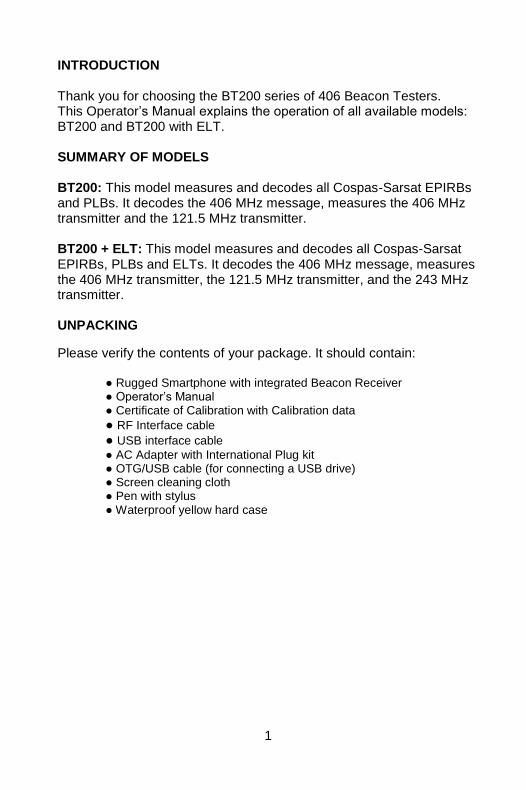
INTRODUCTION
Thank you for choosing the BT200 series of 406 Beacon Testers. This Operator’s Manual explains the operation of all available models: BT200 and BT200 with ELT. SUMMARY OF MODELS BT200: This model measures and decodes all Cospas-Sarsat EPIRBs and PLBs. It decodes the 406 MHz message, measures the 406 MHz transmitter and the 121.5 MHz transmitter. BT200 + ELT: This model measures and decodes all Cospas-Sarsat EPIRBs, PLBs and ELTs. It decodes the 406 MHz message, measures the 406 MHz transmitter, the 121.5 MHz transmitter, and the 243 MHz transmitter. UNPACKING
Please verify the contents of your package. It should contain:
Rugged Smartphone with integrated Beacon Receiver Operator’s Manual Certificate of Calibration with Calibration data
RF Interface cable
USB interface cable
AC Adapter with International Plug kit OTG/USB cable (for connecting a USB drive) Screen cleaning cloth Pen with stylus Waterproof yellow hard case
2
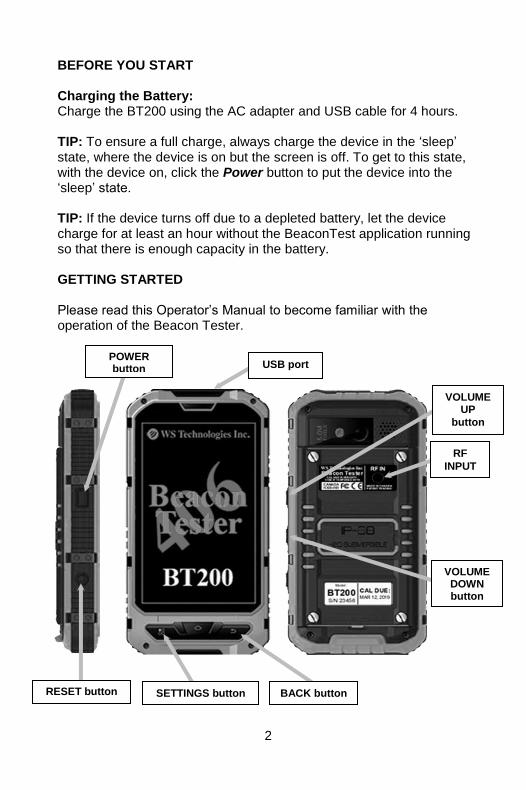
BEFORE YOU START Charging the Battery: Charge the BT200 using the AC adapter and USB cable for 4 hours. TIP: To ensure a full charge, always charge the device in the ‘sleep’ state, where the device is on but the screen is off. To get to this state, with the device on, click the Power button to put the device into the ‘sleep’ state. TIP: If the device turns off due to a depleted battery, let the device charge for at least an hour without the BeaconTest application running so that there is enough capacity in the battery. GETTING STARTED Please read this Operator’s Manual to become familiar with the operation of the Beacon Tester.
POWER button
SETTINGS button RESET button
RF
INPUT
BACK button
USB port
VOLUME UP
button
VOLUME DOWN button
3
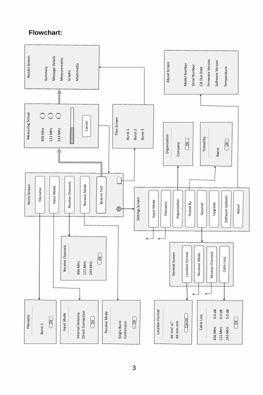
Flowchart:

4
Running the Beacon Tester Application: Turn on the device by pressing and holding the Power button on the left side for 5 seconds then releasing. The device will boot up. Unlock the screen by sliding the lock icon.
Power Button

5
Launch the Beacon Tester application by tapping the BeaconTest icon on the device:
The 406 Beacon Tester title screen will show for a few seconds followed by the Home screen:
BEACON TEST button
BeaconTest icon
SETTINGS button
FILES button
Receive Mode field
Receive Channels
field
Input Mode field
Filename field

6
WARNING!
WHEN USING DIRECT CONNECTION INPUT DO NOT EXCEED A CONTINUOUS POWER LEVEL GREATER THAN 2 WATTS. DAMAGE WILL RESULT!
Selecting the Desired Measurement Filename:
tap the Filename field.
enter the desired measurement file name.
select the Auto Increment Filename box if you wish to have the filename number Auto Increment after each measurement.
tap OK.
NOTE: Do not use forbidden file name characters: / \ : * ? “ < > | Selecting the Input Mode:
tap the Input Mode field. The following screen will appear.
select Internal Antenna to use the internal antenna when receiving the beacon signal through the air.
select Direct Connection to use the 50Ω input port along with the RF Interface cable connected directly to the beacon. Also, use this mode when using the WST RF Screen Box (model TSE100) with the beacon and tester connected directly and both located in the RF Screen Box. NOTE: Using Direct Connection will result in absolute power measurement units (dBm). Using the Internal Antenna will result in relative power measurement units (%).

7
Selecting the Desired Receive Channels:
tap the Receive Channels field. The following screen will appear.
select the desired channels you wish to receive.
tap OK. Selecting the Desired Receive Mode:
tap the Receive Mode field. The following screen will appear.
select the desired mode.
tap OK. In Single Burst mode, the receiver will capture one set of measurements and terminate the test. In Continuous mode, the receiver will continue to capture sets of measurements until Cancel is tapped.

8
SETTING THE CONFIGURATION SETTINGS
tap the Settings button (the icon at the bottom left of screen or the lower left button on the device). Setting the Organization and Tested By Names:
tap the Organization field.
enter the desired Organization name.
tap OK.
tap the Tested By field.
enter the desired name.
tap OK.
NOTE: The entered Organization and Tested By names will appear on each Test Report and in the data file.
Tested By field button
Organization field button
Upgrade field button
General field button
Software Update field
About field

9
General:
tap on the General field. The General screen will allow changing Location Coordinate formats, Receive Mode, Receive Channels, and entering Cable Loss factors.
Location Coordinates Setting:
tap on the Location Coordinate Format field
select the box relating to your desired location coordinate display.
NOTE: dd.dddd° is decimal degrees; dd° mm’ ss” is degrees/minutes/seconds; dd° mm.mm’ is degrees/decimal minutes.

10
Selecting the Desired Receive Mode:
tap the Receive Mode field. The following screen will appear.
select the desired mode. In Single Burst mode, the receiver will capture one set of measurements. In Continuous mode, the receiver will continue to capture sets of measurements until Cancel is tapped. Selecting the Desired Receive Channels:
tap the Receive Channels field. The following screen will appear.
select the desired channels you wish to receive.
tap OK.

11
Entering Cable Loss Factors:
tap on the Cable Loss (CL) field.
enter the desired cable loss factor for each frequency.
tap OK. When the Input Mode is set to Direct Connection, the cable loss factor will be included in the power measurements for each frequency. Upgrade: When upgrading to add new features, such as the ELT option, you may purchase an upgrade code.
tap on the Upgrade field.
enter the upgrade code (supplied by WS Technologies Inc. when you purchase the Upgrade). Software Updates: Software updates are available free of charge to all users. Three methods of downloading and installing new Beacon Tester software are available from: the Google Play Store; the BT200 via WST website; or via a connected PC.

12
Software Update Instructions: From the Google Play Store: Note: If Beacon Tester version 1.00 is currently installed, it must be manually removed by going to the device Settings>Apps>Beacon Tester>Uninstall prior to downloading the app from the Google Play Store. On the device, tap on the Google Play Store icon to go to the Google Play Store and search for the Beacon Tester app. Tap Install to install the WS Technologies Inc. Beacon Tester app. If you wish to have the Google Play Store automatically update the app when updates are available, then from the Pull Down menu check the Auto-update box.
Google Play Store
icon
Pull Down menu

13
From the BT200 handheld device:
make sure the BT200 device has a network connection capable of accessing the internet.
from the Settings > Software Updates screen, tap on the hyperlink or use a browser to navigate to wst.ca/BT200software.html
if a newer software version is available then click the Download link.
save the file to the Download directory in the BT200 device.
once downloaded, use File Manager on the BT200 device to navigate to the download directory.
locate the downloaded .apk file and tap to install.
once installation is complete, run the Beacon Test application and go to Settings > About to verify the new Software Version was installed. From a PC:
from your network-connected PC, navigate to wst.ca/BT200software.html
if a newer software version is available then click Download and save to Desktop.
connect the BT200 device to the PC using the USB cable.
on the BT200 device tap Turn on USB storage.
on the PC, locate the connected drive representing the BT200 device.
copy the .apk file downloaded to the Desktop to the Download directory on the BT200 device.
once downloaded, tap Turn Off USB storage on the BT200 device.
disconnect the USB cable.
on the BT200 device use File Manager to navigate to Download directory and tap on the downloaded .apk file. This will install the new software.
once installation is complete, run the Beacon Test application and go to Settings > About to verify the new Software Version was installed.
Software Update
hyperlink

14
About: Tapping on the About field will display the following screen: The About screen provides information relating to the BT200. The information provided includes the Model Number, Serial Number, Calibration Due Date, Firmware Revision, Software Revision, and internal temperature of the BT200.

15
MAKING MEASUREMENTS NOTE: Interpreting the results provided by the Beacon Tester requires some knowledge of beacon requirements. Using the self test mode of the beacon may result in some measurements being outside the required limits due to the lack of a warm-up period.
WARNING! DO NOT ACTIVATE ANY BEACON IN ITS NORMAL ACTIVATE MODE UNLESS THE BEACON IS IN A SCREEN BOX (TSE100) OR A SCREEN ROOM. DOING SO COULD RESULT IN A FALSE DISTRESS ALERT.
General:
All measurements will produce a Test Report in a PDF format, and a data file in comma separated values (.csv) format for easily importing into a spreadsheet for data parsing and saving. Measurement results are stored in the BT200 device. Each measurement will be saved in a folder with the same name as the measurement filename. For example, a measurement with the filename “Burst-1” is made on a beacon. When the measurement is completed, the following is created: <Burst-1> folder name <images> folder contain graphic images Burst-1.csv measurement data file Burst-1.pdf PDF Test Report When the Auto Increment feature is enabled in the Filename field, the next measurement will be named Burst-2. When the Receive Mode settings are set to Continuous Receive, then each subsequent burst measurement data will be appended to the stored data file.

16
Connecting the Beacon: There are 2 methods for receiving a signal from a beacon – using the Internal Antenna or using the Direct Connection mode. Internal Antenna:
select Internal Antenna from the Input Mode on the Home screen. When a measurement is completed, the power level units will be shown in %, with 100% being displayed when the tester is very close to the antenna of the transmitting beacon. Direct Connection:
select Direct Connection from the Input Mode on the Home screen.
attach the RF Interface Cable (p/n 130-024) to the RF IN connector located on the rear of the BT200 device. Attach the beacon. When a measurement is completed, the power level units will be shown in dBm. This measurement is very accurate. If cable loss factors are setup in the Settings > General > Cable Loss section, then these factors are included in the power level measurements.
17
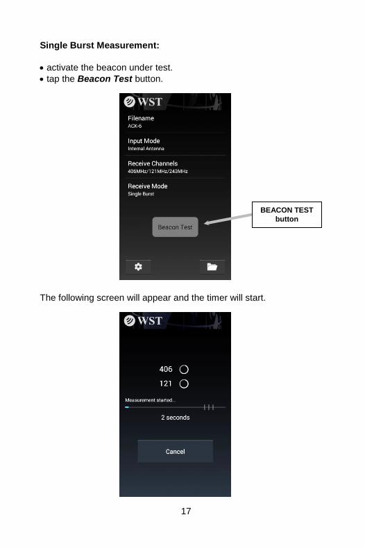
Single Burst Measurement:
activate the beacon under test.
tap the Beacon Test button.
The following screen will appear and the timer will start.
BEACON TEST
button
18
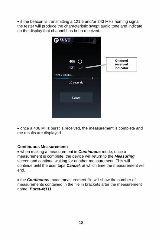
if the beacon is transmitting a 121.5 and/or 243 MHz homing signal the tester will produce the characteristic swept audio tone and indicate on the display that channel has been received.
once a 406 MHz burst is received, the measurement is complete and the results are displayed. Continuous Measurement:
when making a measurement in Continuous mode, once a measurement is complete, the device will return to the Measuring screen and continue waiting for another measurement. This will continue until the user taps Cancel, at which time the measurement will end.
the Continuous mode measurement file will show the number of measurements contained in the file in brackets after the measurement name: Burst-4(11)
Channel received indicator
19
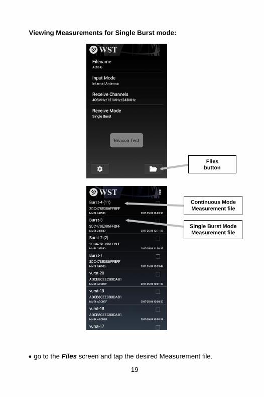
Viewing Measurements for Single Burst mode:
go to the Files screen and tap the desired Measurement file.
Files button
Continuous Mode
Measurement file
Single Burst Mode
Measurement file
20
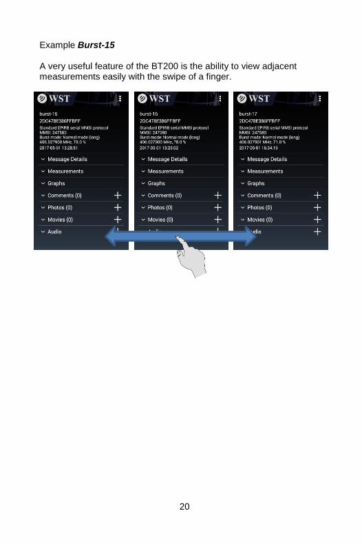
Example Burst-15 A very useful feature of the BT200 is the ability to view adjacent measurements easily with the swipe of a finger.

21
Viewing Measurements for Continuous mode:
go to the Files screen and tap the desired Measurement file. Example Burst-4(11)
you can now view the first burst and scroll horizontally through the remaining bursts within the same filename.
the slider at the top of the screen shows which burst you are viewing. Note: In Continuous mode, all beacons within range of the tester will be captured. The 15 Hex IDs may not necessarily be the same.

22
MEASUREMENT RESULTS Results Screen: The Results screen consists of a summary section, along with collapsible sections for Message Details, Measurements, and Graphs. Sections can be expanded or collapsed by tapping on the section headings. The screen can be scrolled up and down using your finger. Summary Section: The Summary section includes:
Filename
15 Hex ID
Beacon information (protocol dependent)
Burst mode (Normal or Self Test mode)
Channel frequency and power level
Date and time of receiving burst
Summary section

23
Message Details: The Message Details section shows the details from the decoded message of the beacon transmission. Measurements:
Message Details section
Measurements section

24
The Measurements section shows the detailed measurements for all received channels. Graphics: The Graphics section displays the Power vs. Time for the 406 MHz burst, the 406 MHz frequency spectrum, and the demodulated Phase vs. Time waveform.
Graphics section
25
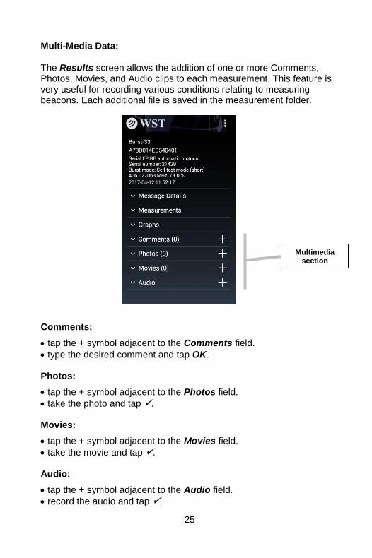
Multi-Media Data: The Results screen allows the addition of one or more Comments, Photos, Movies, and Audio clips to each measurement. This feature is very useful for recording various conditions relating to measuring beacons. Each additional file is saved in the measurement folder. Comments:
tap the + symbol adjacent to the Comments field.
type the desired comment and tap OK. Photos:
tap the + symbol adjacent to the Photos field.
take the photo and tap . Movies:
tap the + symbol adjacent to the Movies field.
take the movie and tap . Audio:
tap the + symbol adjacent to the Audio field.
record the audio and tap .
Multimedia section

26
More than one multimedia file can be recorded. The number of files is shown in brackets beside each section. FILES Getting to the Files screen:
tap Files from the Home screen.
tapping on a file name will select and display the that measurement. Deleting Files:
tap and hold the file to be deleted.
tap on any other files you also wish to delete.
tap the Delete symbol.
Delete symbol
27
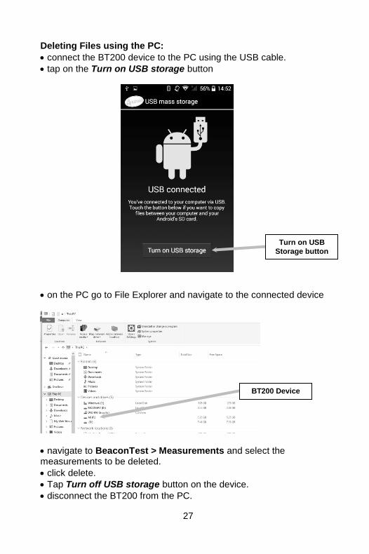
Deleting Files using the PC:
connect the BT200 device to the PC using the USB cable.
tap on the Turn on USB storage button
on the PC go to File Explorer and navigate to the connected device
navigate to BeaconTest > Measurements and select the measurements to be deleted.
click delete.
Tap Turn off USB storage button on the device.
disconnect the BT200 from the PC.
Turn on USB
Storage button
BT200 Device
28
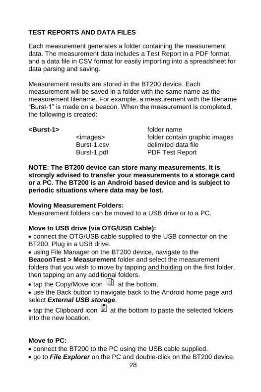
TEST REPORTS AND DATA FILES
Each measurement generates a folder containing the measurement data. The measurement data includes a Test Report in a PDF format, and a data file in CSV format for easily importing into a spreadsheet for data parsing and saving. Measurement results are stored in the BT200 device. Each measurement will be saved in a folder with the same name as the measurement filename. For example, a measurement with the filename “Burst-1” is made on a beacon. When the measurement is completed, the following is created: <Burst-1> folder name <images> folder contain graphic images Burst-1.csv delimited data file Burst-1.pdf PDF Test Report NOTE: The BT200 device can store many measurements. It is strongly advised to transfer your measurements to a storage card or a PC. The BT200 is an Android based device and is subject to periodic situations where data may be lost. Moving Measurement Folders: Measurement folders can be moved to a USB drive or to a PC. Move to USB drive (via OTG/USB Cable):
connect the OTG/USB cable supplied to the USB connector on the BT200. Plug in a USB drive.
using File Manager on the BT200 device, navigate to the BeaconTest > Measurement folder and select the measurement folders that you wish to move by tapping and holding on the first folder, then tapping on any additional folders.
tap the Copy/Move icon at the bottom.
use the Back button to navigate back to the Android home page and select External USB storage.
tap the Clipboard icon at the bottom to paste the selected folders into the new location. Move to PC:
connect the BT200 to the PC using the USB cable supplied.
go to File Explorer on the PC and double-click on the BT200 device.

29
navigate to BeaconTest > Measurements and select the measurement folders you wish to move.
using standard Windows techniques, Copy and Paste the selected measurement folders to the desired location on the PC. Measurement Files: A folder will exist for each successfully completed measurement. Each measurement folder will contain the following files:
PDF Test Report: The PDF Test Report contains all of the measurement data along with 406 graphics showing the Power vs Time, 406 Spectrum, and 406 Phase Modulation. The Test Report can be viewed from the PC and printed. Measurement Data File: The Measurement Data file is a delimited text file (csv format) suitable for importing into a spreadsheet or database.

30
The header section of the file contains the Filename, Tester Model/Serial Number, Tester Cal Due Date, Tester Temperature, Input Mode, Cable Loss factors, Organization Name, and Tested By name. The body contains the Date, Burst #, 15 Hex ID, Full HEX, Latitude, Longitude, 406 Freq (MHz), 406 Power (dBm or %), 406 Power Rise Time (ms), 406 Pre-Burst Level (dBm), 406 Rep Period (s), 406 Bit Rate (bps), 406 Unmodulated CW Time (ms), 406 Transmission Time (ms), 406 Mod Rise Time (us), 406 Mod Fall Time (us), 406 Positive Phase (rad), 406 Negative Phase (rad), 406 Phase Symmetry (%), 121 Freq (MHz), 121 Peak Power (dBm or %), 121 Sweep Direction, 121 Audio Freq Upper (Hz), 121 Audio Freq Lower (Hz), 121 Audio Sweep Range (Hz), 121 Mod Index (%), 121 Sweep Rep Rate (Hz), 121 Duty Cycle (%), 243 Freq (MHz), 243 Peak Power (dBm or %), 243 Sweep Direction, 243 Audio Freq Upper (Hz), 243 Audio Freq Lower (Hz), 243 Audio Sweep Range (Hz), 243 Mod Index (%), 243 Sweep Rep Rate (Hz), 243 Duty Cycle (%), Full Binary, and Decoded Message Details. When the Tester is in Continuous Mode, each set of measurement data will be appended to the measurement data file. Graphics Files: The Measurement folder contains the data used for the graphics files. This data represents the Graphic plot with 200 data points in a CSV format. The sub-folder Images, contains the graphic images created for each measurement. Multimedia Files: The Measurement folder also contains the multimedia files including Comments, Photos, Movies, and Audio Clips. SOFTWARE UPDATES Software updates are available free of charge on the WS Technologies Inc. website: www.wst.ca/BT200software.html
31
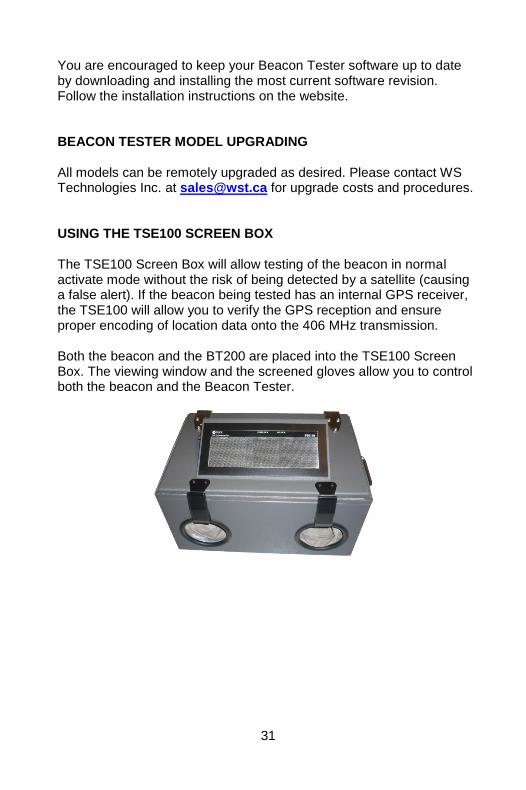
You are encouraged to keep your Beacon Tester software up to date by downloading and installing the most current software revision. Follow the installation instructions on the website. BEACON TESTER MODEL UPGRADING All models can be remotely upgraded as desired. Please contact WS Technologies Inc. at [email protected] for upgrade costs and procedures. USING THE TSE100 SCREEN BOX The TSE100 Screen Box will allow testing of the beacon in normal activate mode without the risk of being detected by a satellite (causing a false alert). If the beacon being tested has an internal GPS receiver, the TSE100 will allow you to verify the GPS reception and ensure proper encoding of location data onto the 406 MHz transmission. Both the beacon and the BT200 are placed into the TSE100 Screen Box. The viewing window and the screened gloves allow you to control both the beacon and the Beacon Tester.
32
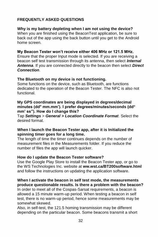
FREQUENTLY ASKED QUESTIONS Why is my battery depleting when I am not using the device? When you are finished using the BeaconTest application, be sure to back out of the app using the back button until you get to the Android home screen. My Beacon Tester won’t receive either 406 MHz or 121.5 MHz. Ensure that the proper Input mode is selected. If you are receiving a beacon self test transmission through its antenna, then select Internal Antenna. If you are connected directly to the beacon then select Direct Connection. The Bluetooth on my device is not functioning. Some functions on the device, such as Bluetooth, are functions dedicated to the operation of the Beacon Tester. The NFC is also not functional. My GPS coordinates are being displayed in degrees/decimal minutes (dd° mm.mm’). I prefer degrees/minutes/seconds (dd° mm’ ss”). How do I change this? Tap Settings > General > Location Coordinate Format. Select the desired format. When I launch the Beacon Tester app, after it is Initialized the spinning timer goes for a long time. The length of time the timer continues depends on the number of measurement files in the Measurements folder. If you reduce the number of files the app will launch quicker. How do I update the Beacon Tester software? Use the Google Play Store to install the Beacon Tester app, or go to the WS Technologies Inc. website at ww.wst.ca/BT200software.html and follow the instructions on updating the application software. When I activate the beacon in self test mode, the measurements produce questionable results. Is there a problem with the beacon? In order to meet all of the Cospas-Sarsat requirements, a beacon is allowed a 15 minute warm-up period. When testing a beacon in self test, there is no warm-up period, hence some measurements may be somewhat skewed. Also, in self-test, the 121.5 homing transmission may be different depending on the particular beacon. Some beacons transmit a short

33
modulated signal, some beacons transmit a shorter unmodulated signal and some beacons transmit no signal. The Beacon Tester may indicate “unable to measure details” or “unmodulated carrier” depending on the beacon characteristics. I am testing an ELT with separate 121.5 and 406 output connectors. What do I do to get the results printed on one Test Report? Connect to the 121.5 transmitter first, then start the test. Once the Beacon Tester gives the indication that the 121.5 signal has been received, switch the cable to the 406 transmitter without stopping the test. Once the 406 burst is received on the Beacon Tester, the measurement will be complete. Is the characteristic swept tone audio that I hear when the Beacon Tester receives a 121.5 MHz signal the actual demodulated audio from the beacon? No, the swept tone audio is just an audio file played when the tester has received a 121 MHz signal. The beacon I want to measure has offset training frequencies on 121.5 and 243 MHz. How do I setup the Beacon Tester to receive these training frequencies? Measuring Training Frequencies is not currently available on the BT200. It will be available in a future software release.
34
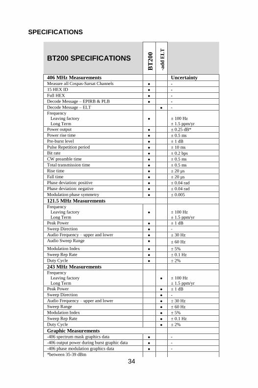
SPECIFICATIONS
BT200 SPECIFICATIONS
BT
20
0
-ad
d E
LT
406 MHz Measurements Uncertainty
Measure all Cospas-Sarsat Channels -
15 HEX ID -
Full HEX -
Decode Message – EPIRB & PLB -
Decode Message – ELT
-
Frequency
Leaving factory
Long Term
± 100 Hz
± 1.5 ppm/yr
Power output ± 0.25 dB*
Power rise time ± 0.5 ms
Pre-burst level ± 1 dB
Pulse Repetition period ± 10 ms
Bit rate ± 0.2 bps
CW preamble time ± 0.5 ms
Total transmission time ± 0.5 ms
Rise time ± 20 µs
Fall time ± 20 µs
Phase deviation: positive ± 0.04 rad
Phase deviation: negative ± 0.04 rad
Modulation phase symmetry ± 0.005
121.5 MHz Measurements Frequency
Leaving factory
Long Term
± 100 Hz
± 1.5 ppm/yr
Peak Power ± 1 dB
Sweep Direction -
Audio Frequency – upper and lower ± 30 Hz
Audio Sweep Range ± 60 Hz
Modulation Index ± 5%
Sweep Rep Rate ± 0.1 Hz
Duty Cycle ± 2%
243 MHz Measurements Frequency
Leaving factory
Long Term
± 100 Hz
± 1.5 ppm/yr
Peak Power ± 1 dB
Sweep Direction -
Audio Frequency – upper and lower ± 30 Hz
Sweep Range ± 60 Hz
Modulation Index ± 5%
Sweep Rep Rate ± 0.1 Hz
Duty Cycle ± 2%
Graphic Measurements -406 spectrum mask graphics data -
-406 output power during burst graphic data -
-406 phase modulation graphics data -
*between 35-39 dBm

35
SPECIFICATIONS (cont’d)
Miscellaneous Parameters RF Range
406 MHz
121.5 MHz/243 MHz
>10 m
>1 m
RF Input VSWR 1.20:1
Dynamic Range
(Antenna equivalent
and Direct)
406 MHz Burst -20 dBm to +40 dBm
121.5 MHz/243 MHz -5 dBm to +35 dBm
Maximum Input Power (Burst) +43 dBm
Maximum Input Power (Continuous) +33 dBm
Operating Temperature Range +5°C to +50°C
Storage Temperature Range -20°C to +60°C
Ingress Rating IP68
RF Input Cable Termination BNC-female
Dimensions and Weight
BT200: w x l x h mm (inches)
Weight
135 (5.31) x 70 (2.76) x 2.0 (0.79)
222 g (0.49 lbs)
Hard Case: w x l x h mm (inches)
Weight
363 (14.29) x 284 (11.18) x 124 (4.88)
1.90 kg (4.2 lbs)
36
REGULATORY INFORMATION CANADA This device complies with Industry Canada’s licence-exempt RSSs. Operation is subject to the following two conditions: (1) This device may not cause interference; and (2) This device must accept any interference, including interference that may cause undesired operation of the device.
USA
NOTE: This equipment has been tested and found to comply with the limits for a Class A digital device, pursuant to part 15 of the FCC Rules. These limits are designed to provide reasonable protection against harmful interference when the equipment is operated in a commercial environment. This equipment generates, uses, and can radiate radio frequency energy and, if not installed and used in accordance with the instruction manual, may cause harmful interference to radio communications. Operation of this equipment in a residential area is likely to cause harmful interference in which case the user will be required to correct the interference at his own expense.
37
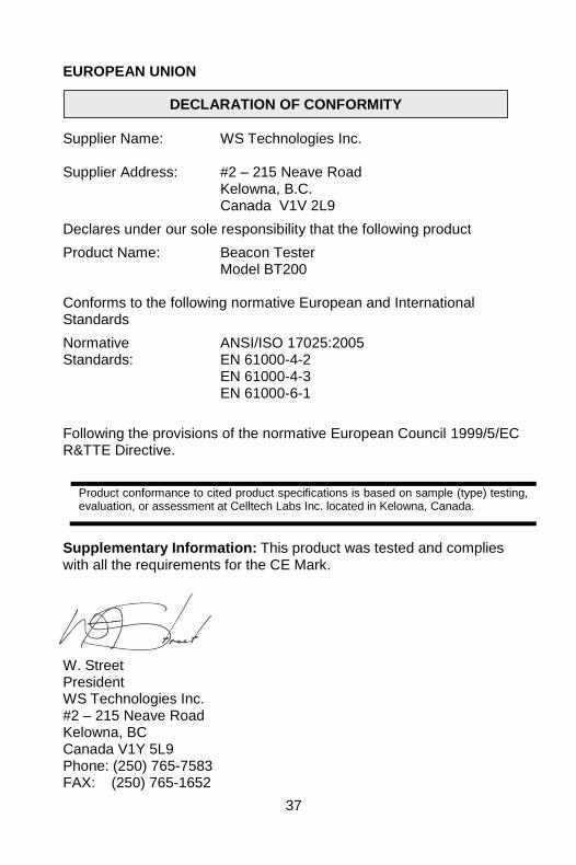
EUROPEAN UNION Supplier Name: WS Technologies Inc. Supplier Address: #2 – 215 Neave Road Kelowna, B.C. Canada V1V 2L9
Declares under our sole responsibility that the following product
Product Name: Beacon Tester Model BT200 Conforms to the following normative European and International Standards
Normative ANSI/ISO 17025:2005 Standards: EN 61000-4-2 EN 61000-4-3 EN 61000-6-1
Following the provisions of the normative European Council 1999/5/EC R&TTE Directive.
Product conformance to cited product specifications is based on sample (type) testing, evaluation, or assessment at Celltech Labs Inc. located in Kelowna, Canada.
Supplementary Information: This product was tested and complies with all the requirements for the CE Mark. W. Street President WS Technologies Inc. #2 – 215 Neave Road Kelowna, BC Canada V1Y 5L9 Phone: (250) 765-7583 FAX: (250) 765-1652
DECLARATION OF CONFORMITY
38
WARRANTY INFORMATION WS Technologies Inc. (WST) warrants the products manufactured by WST to be free from defects in material and workmanship for one year from the date of shipment. Liability of WST under the foregoing warranty is limited to the replacement or repair, at the option of WST, of any products which show defective workmanship or materials within one year from the date of shipment, which replacement shall be made Exworks (EXW) WST's facility in Kelowna, BC, CANADA, upon proof satisfactory to WST of the defect claimed. Except for the foregoing warranty, WST makes no other warranty, express or implied, as to the merchantability or fitness for a particular purpose of products shipped or the performance thereof, and does not make any warranty to the purchaser's customers or agents. CALIBRATION The BT200 series of Beacon Testers has been designed to have a standard one year calibration cycle. The calibration date appears on the Calibration Certificate supplied with the Beacon Tester and the Cal Due date appears on the back of the BT200 device. Before returning a unit for calibration, email [email protected] to obtain an RMA (Return Materials Authorization) number and shipping instructions. Once calibrated, a new Cal Due date label will be placed on the back of the unit and a new Calibration Certificate will be issued. RETURNS An RMA (Return Materials Authorization) number must be obtained by emailing [email protected] . If the unit being returned is not covered under warranty, a minimum repair charge will apply. If damage is severe or the products have been tampered with, there may be additional charges.
39
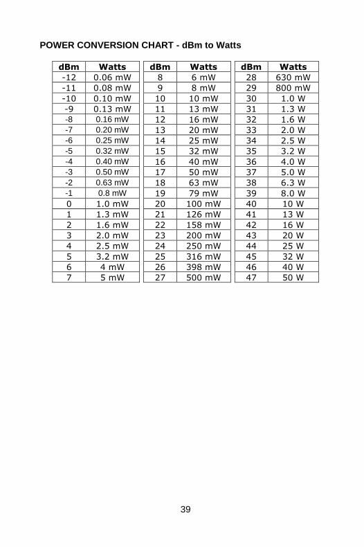
POWER CONVERSION CHART - dBm to Watts
dBm Watts dBm Watts dBm Watts
-12 0.06 mW 8 6 mW 28 630 mW
-11 0.08 mW 9 8 mW 29 800 mW
-10 0.10 mW 10 10 mW 30 1.0 W
-9 0.13 mW 11 13 mW 31 1.3 W
-8 0.16 mW 12 16 mW 32 1.6 W
-7 0.20 mW 13 20 mW 33 2.0 W
-6 0.25 mW 14 25 mW 34 2.5 W
-5 0.32 mW 15 32 mW 35 3.2 W
-4 0.40 mW 16 40 mW 36 4.0 W
-3 0.50 mW 17 50 mW 37 5.0 W
-2 0.63 mW 18 63 mW 38 6.3 W
-1 0.8 mW 19 79 mW 39 8.0 W
0 1.0 mW 20 100 mW 40 10 W
1 1.3 mW 21 126 mW 41 13 W
2 1.6 mW 22 158 mW 42 16 W
3 2.0 mW 23 200 mW 43 20 W
4 2.5 mW 24 250 mW 44 25 W
5 3.2 mW 25 316 mW 45 32 W
6 4 mW 26 398 mW 46 40 W
7 5 mW 27 500 mW 47 50 W

40
Notes: