bdem update & lg girder - ltrc.lsu.edu · 7 bdem rev. 7 –published part ii volume 3...
TRANSCRIPT

BDEM UPDATE & LG GIRDER
Louisiana Transportation Conference2/27/2018
Zhengzheng “Jenny” Fu, P.E.Assistant Bridge Design Administrator
LADOTD Bridge Design Section
1

ACKNOWLEDGEMENTS
SDR Engineering Consultants, Inc.
DOTD Staff
Dr. Ayman Okeil, LSU
All Users
2

OUTLINE
BDEM Revisions (Rev. 7 and 8)
LG Girder Special Details
Future Work
3
4
Index
Preface
Revision History
Part I Policies and Procedures
Part II Design Specifications (Supplement AASHTO Specifications)
Volume 1 - Bridge Design
Volume 2 - Movable Bridge Design
Volume 3 - Structural Supports for Permanent Highway Signs and High Mast Lighting
Volume 4 - Highway Safety Hardware
Volume 5 - Bridge Evaluation/Rating
Part III Design and Detail Aids
Part IV Background Information
5
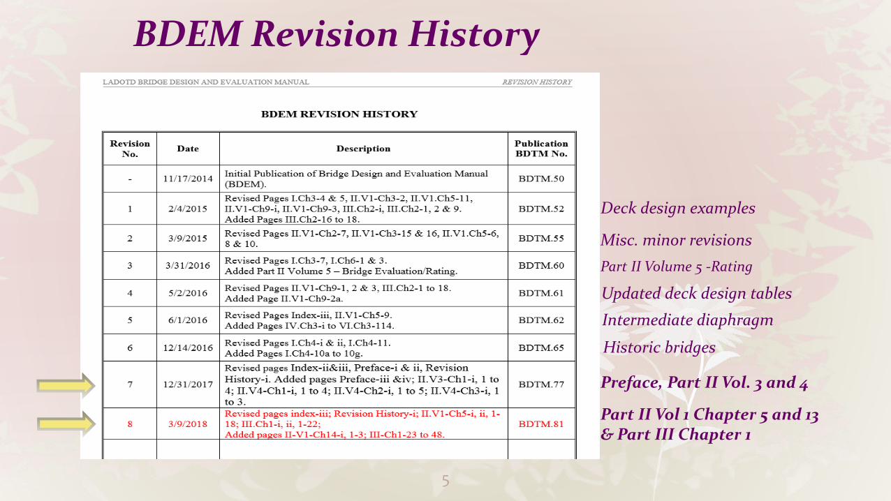
BDEM Revision History
Part II Vol 1 Chapter 5 and 13 & Part III Chapter 1
Preface, Part II Vol. 3 and 4
Historic bridges
Updated deck design tables
Misc. minor revisions
Part II Volume 5 -Rating
Deck design examples
Intermediate diaphragm

6
BDEM Rev. 7 – Updated Preface
BDEM organization and format Maintenance and revision of BDEM (including implementation
policy for new edition of AASHTO Specifications) Implementation policy of BDEM revisions for consultant and in-
house projects Archived Manuals ( including archived BDEM pages and yearly
version of BDEM) Guidelines and BDTMs (part of BDEM)
7
BDEM Rev. 7 – Published Part II Volume 3 – Permanent Highway Signs and High Mast Lighting
Supplements AASHTO LRFD Specifications for Structural Supports for Highway Signs, Luminaires and Traffic Signals
Discussed specific design, details and plan preparation for DOTD permanent highway overhead signs, breakaway signs and luminaires
Referenced DOTD special details for Roadside Traffic Signs and Overhead Traffic Signs.
8
BDEM Rev. 7 – Published Part II Volume 4 –Highway Safety Hardware
Referenced AASHTO Roadside Design Guide (RDG) as a guide Provided design, detail and plan preparation information for DOTD
roadside barriers, median barriers, end treatments, and temporary barriers
Discussed general criteria, design process, standard plans, special details, specifications, EDSMs, and DOTD Approved Material Lists related to highway safety hardware.

9
BDEM Rev. 8 – Revised Part II Volume 1 -Chapter 5 – Concrete Structures
Section 5.4 Material Properties – Included a Structural Concrete Class Summary Table

10
BDEM Rev. 8 – Revised Part II Volume 1 -Chapter 5 – Concrete Structures
Section 5.7.3.6.2 Deflection and Camber – Clarified deflection and camber definitions and revised symbols
Deflections Estimated Cambers Field Measured Camber*D1 –due to prestress force at transfer C1 – at release = D1-D2 MC1 – measured at 18 hoursD2 –due to girder self-weight C2 – at erection (PCI Multiplier method) after releaseD3 –due to non-composite dead load = 1.80D1 – 1.85D2 MC2 – measured at 21 days D4 –due to composite dead load C3 – final = C1 – D5 prior to deck pour
(exclude wearing surface) D5 – due to all dead loads = D3+D4
* Contractor is required to provide these measurements.
11
BDEM Rev. 8 – Revised Part II Volume 1 -Chapter 5 – Concrete Structures
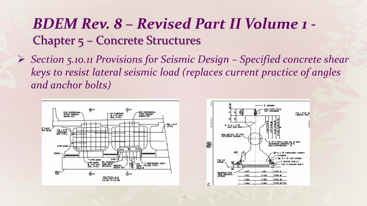
Section 5.10.11 Provisions for Seismic Design – Specified concrete shear keys to resist lateral seismic load (replaces current practice of angles and anchor bolts)

12
BDEM Rev. 8 – Revised Part II Volume 1 -Chapter 5 – Concrete Structures
Section 5.11.4 Development of Prestressing Strand – Clarified policy on straight, debonded and draped strands.
Straight strands shall be used whenever possible.
Debonded strands are not allowed without prior approval.
Draped strands are allowed when needed, however tie down points shall be kept consistent within a project whenever possible. The uplift force at each tie down device shall be limited to 40 kips.

13
BDEM Rev. 8 – Revised Part II Volume 1 -Chapter 5 – Concrete Structures
Section 5.14.1.2 – Precast Beams
Specified new concrete girder policy Included a girder efficiency study in commentary Referenced new PCI Report No. CB-02-16 “Recommended Practice for
Lateral Stability of Precast, Prestressed Concrete Bridge Girders”.

14
BDEM Rev. 8 – Revised Part II Volume 1 -Chapter 5 – Concrete Structures
Girder Policy
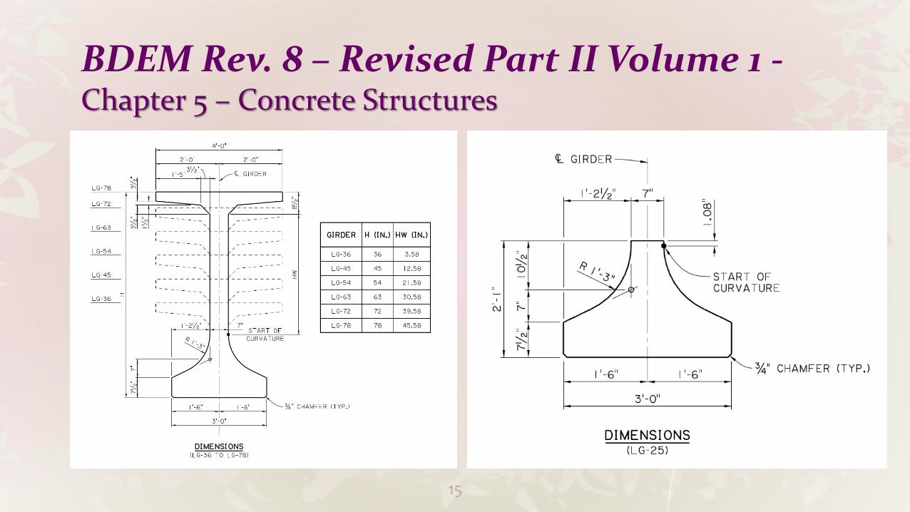
LG girders (LG-25 to LG 78) shall be used for all new construction, bridge widening, and rehabilitation projects.
AASHTO type girders (Type II, III, IV, BT-72 and BT-78) and Quad Beam can be used for rehabilitation projects with prior approval.
15
BDEM Rev. 8 – Revised Part II Volume 1 -Chapter 5 – Concrete Structures
16
BDEM Rev. 8 – Revised Part II Volume 1 -Chapter 5 – Concrete Structures
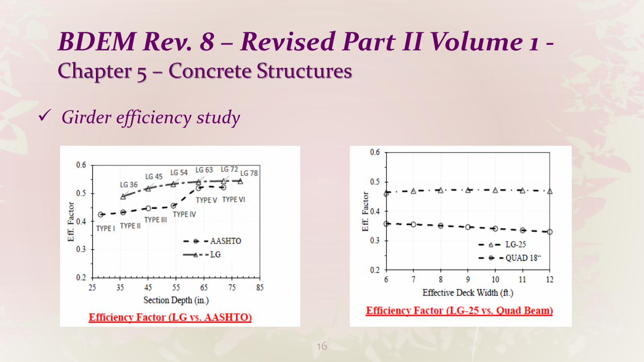
Girder efficiency study

17
BDEM Rev. 8 – Revised Part II Volume 1 -Chapter 5 – Concrete Structures
Girder Stability
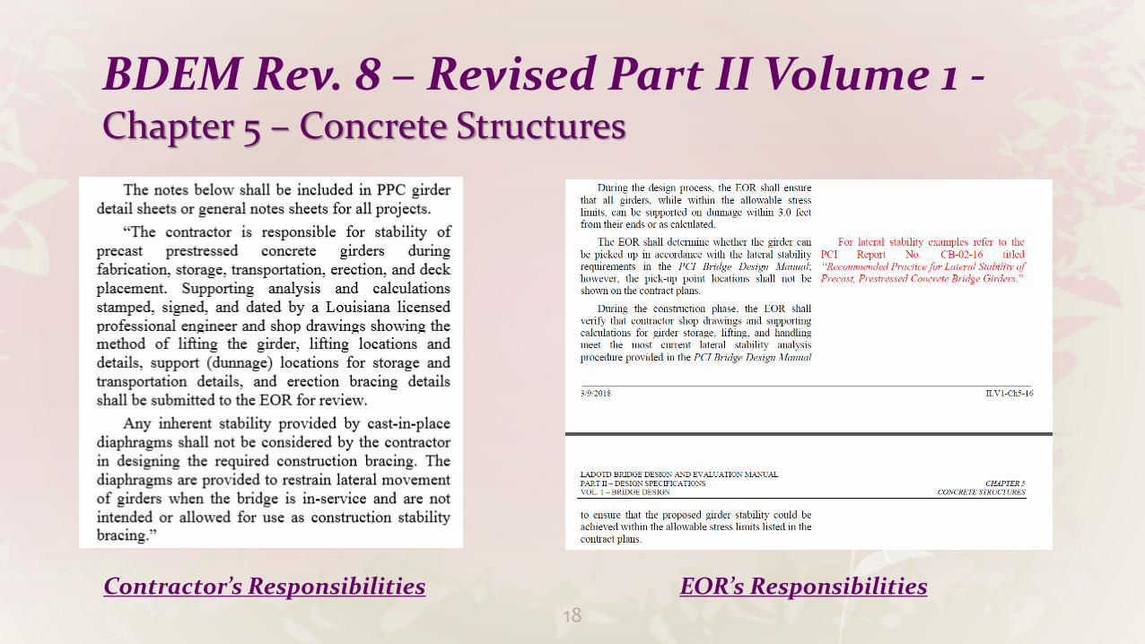
Girder stability during each phase of construction is the responsibility of the contractor, however EOR is responsible for designing a girder that can be picked up and supported on dunnage.
18
BDEM Rev. 8 – Revised Part II Volume 1 -Chapter 5 – Concrete Structures
Contractor’s Responsibilities EOR’s Responsibilities
19
BDEM Rev. 8 – Revised Part II Volume 1 -Chapter 5 – Concrete Structures
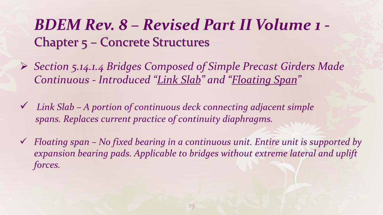
Section 5.14.1.4 Bridges Composed of Simple Precast Girders Made Continuous - Introduced “Link Slab” and “Floating Span”
Link Slab – A portion of continuous deck connecting adjacent simple spans. Replaces current practice of continuity diaphragms.
Floating span – No fixed bearing in a continuous unit. Entire unit is supported by expansion bearing pads. Applicable to bridges without extreme lateral and uplift forces.

20

21
22
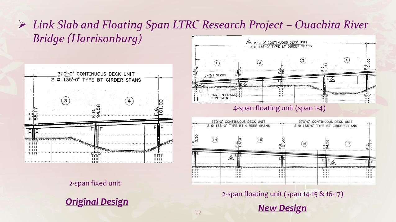
Link Slab and Floating Span LTRC Research Project – Ouachita River Bridge (Harrisonburg)
2-span fixed unit
New Design
4-span floating unit (span 1-4)
Original Design2-span floating unit (span 14-15 & 16-17)
23
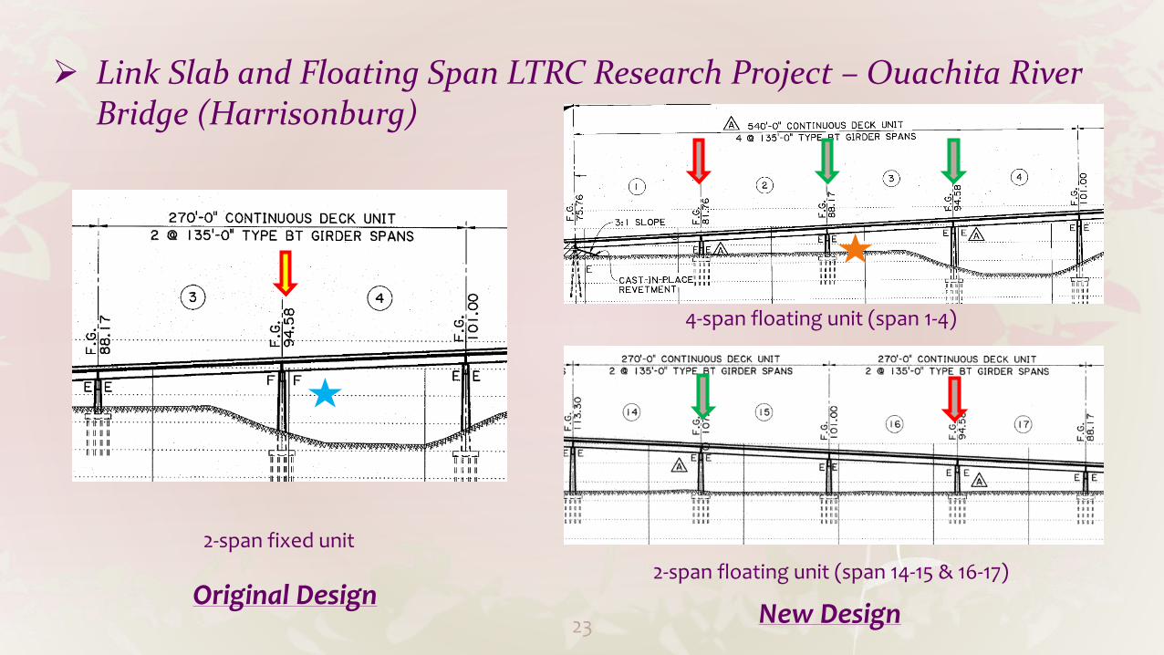
Link Slab and Floating Span LTRC Research Project – Ouachita River Bridge (Harrisonburg)
2-span fixed unit
New Design
4-span floating unit (span 1-4)
Original Design2-span floating unit (span 14-15 & 16-17)

24
Link Slab and Floating Span LTRC Research Project – Ouachita River Bridge (Harrisonburg)
New DesignOriginal Design
F E

25
BDEM Rev. 8 - Part II Volume 1 Chapter 14 – Joints
and Bearings
New Chapter
Section 14.6.2 – Established policy for the use of bearing types and riser types. Specified method B and additional design and detail requirements for steel-reinforced elastomeric bearing design.

26
BDEM Rev. 8 - Part II Volume 1 Chapter 14 –
Joints and Bearings
27
BDEM Rev. 8 - Part III Chapter 1 – LG Girder
Section 1.1 – LG Girder Preliminary Design Charts
Section 1.2 – LG Girder Bearing Design Charts
Section 1.3 – LG Girder Special Details

28
BDEM Rev. 8 - Part III Chapter 1 – LG Girder
Section 1.1 – LG Girder Preliminary Design Charts
29
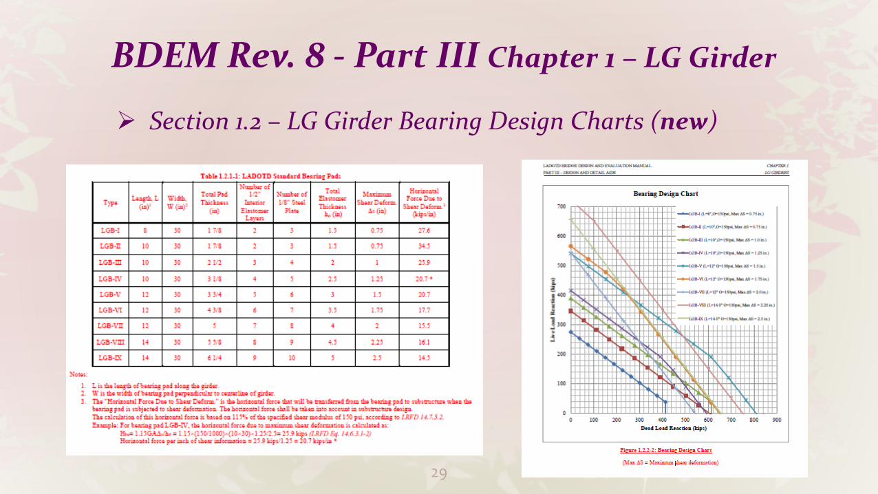
BDEM Rev. 8 - Part III Chapter 1 – LG Girder
Section 1.2 – LG Girder Bearing Design Charts (new)

30
BDEM Rev. 8 - Part III Chapter 1 – LG Girder
Section 1.2 – LG Girder Bearing Design Examples (new)

31
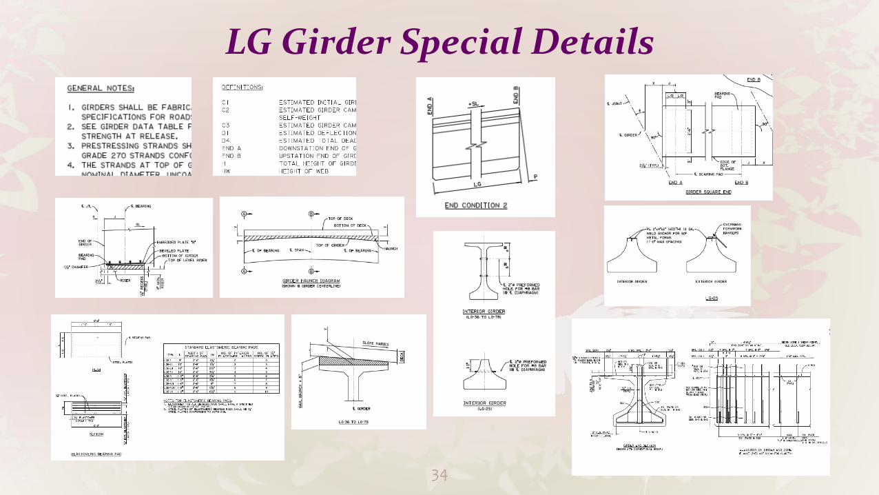
BDEM Rev. 8 - Part III Chapter 1 – LG Girder
Section 1.3 – LG Girder Special Details
Common Details + Specific Details for each girder type

32
LG Girder Special Details

33
LG Girder Special Details
34
LG Girder Special Details

35
LG Girder Special Details

36
Future Work
Part II Volume 5 – Clarify As-Designed Rating and As-Built Rating Requirement
Implement 8th Edition of AASHTO Spec.
Part I – Policies and Procedures
Part II Volume 1 Chapter 10 – Geotechnical Provisions
LU Girder Design Aids and Special Details

Thank you!
37