bdd 611 e - balluffusa.balluff.com/manuals/bdd displays/bdd_611_e.pdf · regional and in-house...
TRANSCRIPT

english
Single-Axis Counter BDD 611Technical Description, User's Guide

Balluff GmbH Schurwaldstrasse 973765 Neuhausen a.d.F.GermanyPhone +49 7158 173-0Fax +49 7158 [email protected]
www.balluff.com
No. 611-150 D/E . Edition 0705; Subject to modification. Replaces edition 0701.
www.balluff.com

Single-Axis Counter BDD 611-R4Q4-0-54-N-00 BDD 611-R3Q4-0-52-N-00 for Incremental Measuring Systems Hardware version 03 Software version 10
1

1. Introduction 4
2. Safety 5 2.1 Personnel Qualifications 5 2.2 Proper use 5 2.3 Safety Notes 6 2.4 Safety Precautions 6
3. Technical Data 7
4. Commissioning 9 4.1 Installation 9 4.2 Connection 9 4.3 Measuring system supply voltage 14 4.4 Switching Output Logic 14 4.5 Keypad and Front Panel 15 4.5.1 Display 15 4.5.2 Key functions 15 4.6 Parameter and Function Levels 16 4.6.1 Entering parameters, changing the device functions 16 4.6.2 Parameter functions 17 4.6.3 Parameter list 30
5. Operation 32 5.1 Display and function keys 32 5.2 Key 32 5.2.1 F key 32 5.2.2 Shift Right key 32 5.2.3 Up key 32 5.2.4 Enter key 32 5.2.5 Absolute -Incremental mode 33 5.2.6 Erasing the EEPROM 33
2

6. RS232 interface 33 6.1 Connecting to the PC 33 6.2 Introduction 34 6.3 Technical Data 34 6.4 Functions 35 6.5 Format determination 35 6.5.1 Forward control 36 6.5.2 Backward control 36 6.5.3 Data control 37 6.6 Send 38 6.7 Receive 39 6.8 Printer mode 40 6.9 Serial commands 40
7. Part Numbering 41
8. List of Illustrations 41
3

1. Introduction The Balluff Single-Axis Counter is a convenient device for visualizing actual values on a machine.
The device has 2 wear-free, short circuit protected driver outputs, PNP sourcing (only with 24V supply voltage).
It is especially designed for use with the Balluff series
BML-S_ _ _-QXY_-M_ _ _-Z0-_ _
with
X = 5, 6 (supply voltage)
Y = 1, 3 (signal level)
Z = E, F, G, H, K, L, M, N, P, R. (min. edge separation) for
Y = 1 encoder signal = RS422
Z = F, G, H, K, L, M, N, P, R. (min. edge separation) for
Y = 3 encoder signal = HTL
The optional RS232 port can be used for parameter setting as well as for direct connection to a printer having a serial port.
4

2. Safety This operating guide contains instructions for ensuring safe and proper installation and operation. If you have any difficulties which cannot be resolved by consulting this guide, please check with the machine manufacturer or vendor for additional information.
Balluff GmbH is not liable for any personal injury or equipment damage resulting from improper commissioning, incorrect operation, misunderstandings or errors contained in this guide or on the display.
Balluff GmbH reserves the right to make technical changes to the equipment or operating guide without prior notice. This means that errors in agreement between the equipment and the guide cannot be precluded.
Pay particular attention to hazard notices in this operating guide.
This equipment description should be carefully read in full before commissioning.
Use of the operating guide presumes that the user is technically qualified.
2.1 Personnel Qualifications
commissioning, installation and operation are to be performed only by qualified personnel. The personnel must have qualifications which are appropriate to their function and activity, e.g.
• Instruction and obligation to observe all application-related, regional and in-house regulations and requirements.
• Training in accordance with the standards of safety technology in the use and care of commensurate safety and work protection equipment.
• Courses in first aid, etc.
2.2 Proper use
This position display has been developed solely for use on industrial machinery.
5

Any further use is considered improper. The manufacturer assumes no liability for damages resulting from such misuse. This risk is assumed solely by the user.
2.3 Safety Notes
The following symbols are used for hazards and other important notes:
The Hazard symbol warns of errors and hazards in commissioning and operation of the controller. This warning notice means a directly threatening hazard to the health of persons and contains special specifications and instructions as well as imperatives and prohibitions for preventing personal injury and damage to equipment.
The Attention symbol means a possible hazardous situation and contains special specifications and instructions as well as imperatives and prohibitions for preventing personal injury and damage to equipment.
The Note symbol indicates important and useful information and provides application tips.
2.4 Safety Precautions
Since the device can be operated with 115V or 230V supply voltage depending on the model, be especially careful not to touch the unit and to secure the device in accordance with the relevant regulations.
The device may not be opened and no screws removed from the housing!
6
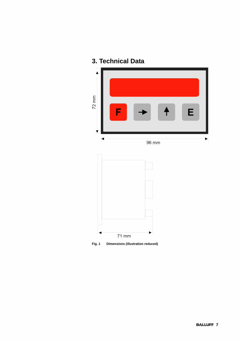
3. Technical Data
Fig. 1 Dimensions (illustration reduced)
7
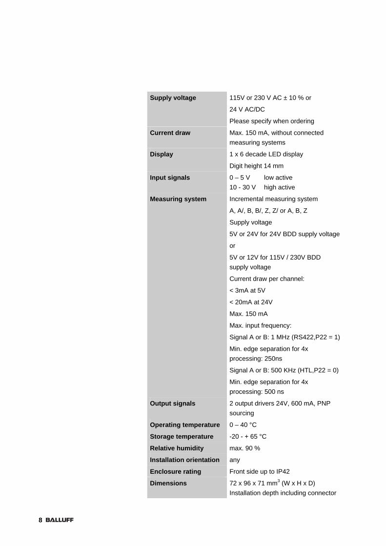
Supply voltage 115V or 230 V AC ± 10 % or
24 V AC/DC
Please specify when ordering
Current draw Max. 150 mA, without connected measuring systems
Display 1 x 6 decade LED display
Digit height 14 mm
Input signals 0 – 5 V low active 10 - 30 V high active
Measuring system Incremental measuring system
A, A/, B, B/, Z, Z/ or A, B, Z
Supply voltage
5V or 24V for 24V BDD supply voltage
or
5V or 12V for 115V / 230V BDD supply voltage
Current draw per channel:
< 3mA at 5V
< 20mA at 24V
Max. 150 mA
Max. input frequency:
Signal A or B: 1 MHz (RS422,P22 = 1)
Min. edge separation for 4x processing: 250ns
Signal A or B: 500 KHz (HTL,P22 = 0)
Min. edge separation for 4x processing: 500 ns
Output signals 2 output drivers 24V, 600 mA, PNP sourcing
Operating temperature 0 – 40 °C
Storage temperature -20 - + 65 °C
Relative humidity max. 90 %
Installation orientation any
Enclosure rating Front side up to IP42
Dimensions 72 x 96 x 71 mm3 (W x H x D) Installation depth including connector
8

4. Commissioning
Most damage to the device is a result of faulty cabling and incorrect parameter values. Therefore commissioning is to be performed only by trained and expert personnel.
4.1 Installation
The device is inserted into a control panel with a cutout of
approx. 93 x 71 mm² and screwed in place using the holder provided.
4.2 Connection
The device is operated with 115V or 230V AC or with 24V DC or AC.
With 115V or 230V AC voltage the relevant regulations for contact protection must be observed in order to prevent personal injury.
Before connecting, compare the part label on the back of the device with the desired connection voltage.
Electrical cables are to be routed in accordance with the respective national regulations (e.g. VDE). Route measuring, signal and power cables separately.
We recommend using only shielded cable connected to GND on the device.
Ensure that no ground loops are created.
9

12345678910
Con1
Con2
Con3
24V 5V
low high
J1
J2
12
3
Con
4
1 2 3 4 5 6 7 8 9 10
12
34
5
Fig. 2 Wiring diagram
Connector and pinouts
CON1 Supply voltage (230V AC)
Terminal strip, 5-pin
Pin 1 L, max. 100 mA
Pin 2 Jumper to Pin 3
Pin 3 Jumper to Pin 2
Pin 4 n
12
34
5
L
NPE
Pin 5 PE, protection ground
10
11
CON1 Supply voltage (115V AC)
Terminal strip, 5-pin
Pin 1 L
Pin 2 n
Pin 3 L
Pin 4 N, max. 100 mA
12
34
5
L
NPE
Pin 5 PE, protection ground
CON1 Supply voltage (24V AC)
Terminal strip, 5-pin
Pin 1 L, max. 300 mA (note part label!)
Pin 2 NC
Pin 3 NC
Pin 4 n
12
34
5
L
NPE
Pin 5 PE, protection ground
CON1 Supply voltage (24V DC)
Terminal strip, 5-pin
Pin 1 +24V, max. 300mA (note part label!)
Pin 2 NC
Pin 3 NC
Pin 4 GND
12
34
5
+24V
GND
Pin 5 GND

CON2 Measuring system input
Terminal strip, 10-pin
Pin 1 GND
Pin 2 +24V, if jumper J1 at left is tied to 24V
( or +12V at 115V, or 230V AC supply voltage)
+5V, if jumper J1 at left is tied to 5V
Pin 3 Signal A
Pin 4 Signal A/ (only for RS422, cf. Parameter P22)
Pin 5 Signal B
Pin 6 Signal B/ (only for RS422, cf. Parameter P22)
Pin 7 Signal Z
Pin 8 Signal Z/ (only for RS422, cf. Parameter P22)
Pin 9 PE connection for shield
Pin 10 PE connection for shield
12

CON3 In-/outputs (unused in-/outputs can be left unconnected)
Outputs are available only together with 24V supply voltage version.
Pin1 Supply for driver output 2
24 V DC
Note part label!
Pin 2 Output for driver output 2 (PNP sourcing)
Pin 3 Supply for driver output 1
24 V DC
Note part label!
Pin 4 Output for driver output 1 (PNP sourcing)
Pin 5 Switching input 4, input voltage 0 – 24 V
Offset dimension/actual value output via RS232
Pin 6 Switching input 3, input voltage 0 – 24 V
Freeze/Stop,/Absolute-Incremental
Pin 7 Switching input 2, input voltage 0 – 24 V
Set
Pin 8 Switching input 1, input voltage 0 – 24 V
Reset
Pin 9 GND for switching inputs
Pin 10 +24V for switching inputs
CON4 RS232 interface (Option)
Terminal strip, 3-pin
Pin 1 RxD
Pin 2 TxD
Pin 3 GND
13

4.3 Measuring system supply voltage
24V 5VJ1
In order to set the supply voltage to the desired level, the back cover of the unit must be removed.
Jumper 1 can then be used to select the desired voltage.
(Observe data sheet for measuring system!)
The respective voltage is printed on the circuit board.
Jumper left 24V, for 24V supply of the measuring system (or 12V for supply voltage 115V or 230V AC).
Jumper right 5V, for 5V supply of the measuring system.
4.4 Switching Output Logic
low highJ2
The switching input logic can be selected using Jumper J2.
The switching states are printed on the circuit board.
Jumper left low, inputs switch to GND.
Jumper right high, inputs switch to +24V.
14

4.5 Keypad and Front Panel
Fig. 3 Front panel
4.5.1 Display The display is used for visualizing the position as well as displaying the parameter values in the parameter levels.
4.5.2 Key functions 1. The F switches from the display level to the calibration and
parameter levels and back.
2. The key is used to select a decade (flashing), which then can be edited in one of the function levels by using the key.
It is also used for changing the parameter numbers in function level 2.
3. The key is used for editing the flashing decade in one of the function levels.
4. The E key is used for confirming an edited value in the function levels.
This key must always be pressed after entering a parameter or calibration value in order to save it.
15

4.6 Parameter and Function Levels
4.6.1 Entering parameters, changing the device functions
When changing control and calibration parameters, always take into account the effects on the overall system:
The parameters may be protected against unintended changes by using a security code.
This may be selected by the machine manufacturer himself.
The device provides two levels, one for entering parameters and one for entering the set value (calibration function).
1. Calibration value function level 2. General parameter level
The F key is sued to activate and exit function and parameter entry.
Use the key to switch back and forth between the levels.
To open a level use the E (Enter) key, which also serves to confirm an input value.
Changes in the parameter setting can result in malfunction, stopping or failure. Changes to the parameter settings should therefore be made only by knowledgeable personnel.
16

Example:
Changing the P 5 parameter in the Func2 level (parameter level):
1. Press the F key (display Func1)
2. Press the key (display Func2)
3. Press the E key (display P 00)
4. Press the key 5 times (display P 05)
5. Press the E key (display e.g. 1)
6. Shift the flashing decade using the key
and increment the value using the key.
7. Confirm the value by pressing the E key. (display P 06)
8. Exit parameter entry by pressing the F key twice. (display shows actual value)
If the parameter level is code-protected, then after Step 1 you must first enter the corresponding code and confirm by pressing E.
4.6.2 Parameter functions The parameters shown in the following are all performed according to the sample
Parameter number Name [unit, minimum/maximum value) Parameter description.
Parameters in which P00 is entered as the unit refer to the unit specified in parameter P00 (function level 2).
Parameters which are filled with index ro can only be read.
17

Calibration level Func1:
P00 Set value [P00/ -99999.999999]
Set value which when actuating the Set input or confirming with E is written to the actual value window.
Parameter level Func2:
P00 Travel distance for factor calculation [any desired length unit/ 1, 10000]
Contains any desired travel distance.
These two parameters are needed so that the display can be set to various mechanical conditions, such as drives, spindle stroke, etc.
1. Any desired travel distance in the desired unit and resolution (P00).
2. The number of increments sent by the measuring system to the display when traveling this distance (P01).
Only if these specifications are entered in P00 and P01 with no rounding error will the display operate correctly over the entire range.
Therefore you should always select a travel distance over which a whole-number quantity of increments is sent by the measuring system.
P01 Increments / travel distance [resolution of the measuring system/ 1, 65000 ]
Number of increments per travel distance entered in P00 (the factor is automatically calculated from P00 and P01).
Example 1: The measuring system in use sends 100 increments to the display over a distance of 1.00 mm. You want the display value to be shown in increments of 1/100 mm. Therefore each increment arriving from the measuring system must be accounted for. You should therefore set P00 and P01 to the same value (e.g. 1, 1 or 10.10 or 100, 100).
18

Example 2: The measuring system in use again has a resolution of 1/100 mm. But here you only want the display value to resolve to one place after the decimal point, i.e. 1/10 mm. This means that over a distance of 1 (0.1 mm) 10 increments are sent by the measuring system to the display. You should therefore set P00 to smaller than P01 by a factor of 10 (e.g. 1, 10 or 10.100 or 100, 1000).
Example 3: A machine with a spindle drive has the following key data: Spindle rise 5.0 mm / absolute encoder with a resolution of 20 increments per revolution. You want the display to resolve down to one decimal place, i.e. in increments of 1/10 mm. This means that over a distance of 50 (5.0 mm) 20 increments are sent by the measuring system to the display. Therefore you should set P00 to 50 and P01 to 20.
For inch settings, enter P00 in inches.
P02 Edge evaluation [../1.3]
The device can evaluate one, two or 4 edges from the measuring system. This parameter must be set depending on the desired resolution and limit frequency of the measuring system. Input value Edge evaluation 1 1 2 2 3 4
P03 Count direction reversal [../0.1]
Changes the count direction of the display from up to down or the reverse. Input value Count direction 0 Count direction standard 1 Count direction inverted
19

P04 Decimal point [Decimal place/ 0, 5]
This parameter is used to set the decimal place within the display.
0 = Turn off decimal place
1 = One decimal place, etc.
Setting the decimal place has no effect on the display resolution.
This is done only with parameters P00 and P01.
P05 Code for calibrate level [6 decade number/ 0, 999999]
By entering a code you can protect the device from calibration in function level 1.
Then you are only able to calibrate to a new value after entering this code.
P06 Code for parameter level [6 Decade number/ 0, 999999]
By entering a code you can protect the parameter values in function level 2 from being overwritten.
Entering parameter values is then only possible after
entering this code.
20

P07 Front panel key functions [Function/ 0, 14]
The front panel keys and E may be assigned special functions beyond the function levels.
Input value Key function 0 Keys have no function 1 E Sets display to 0 2 Sets display to set value 3 Function 1 and 2 active 4 E activates offset dimension
If this function is active, the offset dimension function is turned off through the external input!
6 Function 2 and 4 active 8 Incremental/Absolute changeover
9 Function 1 and 8 active 10 Function 2 and 8 active 11 Function 1, 2 and 4 active 12 Function 4 and 8 active 13 Function 1, 4 and 8 active 14 Function 2, 4 and 8 active 16 E Switches the display value,
as well as all important parameters, to inches or back to mm
17 Function 1 and 16 active, etc.
P08 Reset logic [type of reset/ 0, 1]
Input value Reset function 0 Static reset
As long as the reset input is active the display remains at 0
1 Dynamic reset The display is set to 0 with the edge of the reset pulse and then resumes counting.
21

P09 Encoder reset [type of encoder reset / 0, 2]
Input value Reset function 0 Reset function turned off by index
pulse from measuring system. 1 Reset function using index pulse
from measuring system with rising edge.
2 Reset function using index pulse from measuring system with falling edge.
P10 Set logic [type of set function/ 0, 1]
Input value Set function 0 Static set
As long as the set input is active, the display remains on the set value.
1 Dynamic set The display is set to the set value with the edge of the reset pulse and then resumes counting.
22

P11 Freeze/Stop/Incremental-Absolute [type of switch function / 0, 2]
Selects the function of the Freeze, Stop, Incremental-Absolute input.
Input value Freeze, Stop function 0 The display is frozen.
The counter continues to count internally.
1 The counter is stopped. Arriving pulses are not processed.
2 The counter switches from absolute to incremental, or the reverse
P12 Offset dimension [P00/ -10000, 10000]
Enter the offset dimension in units of length, such as xx.x mm or x.xx inches.
This value is subtracted from the display value when the offset measurement contact is activated.
When the input is deactivated the value is added again.
23

P13 Switching input logic [binary code/ 0.15 ]
In machine building both normally open and normally closed devices are used as electrical switches.
To be able to adapt the device quickly to any hardware, the switching behavior of the inputs must be determined using this parameter.
The respective settings can be found in the tables below.
1. Inputs switch to GND
Terminal 5 Terminal 6 Terminal 7 Terminal 8 P13
N.O. N.O. N.O. N.O. 0
N.C. N.O. N.O. N.O. 1
N.O. N.C. N.O. N.O. 2
N.C. N.C. N.O. N.O. 3
N.O. N.O. N.C. N.O. 4
N.C. N.O. N.C. N.O. 5
N.O. N.C. N.C. N.O. 6
N.C. N.C. N.C. N.O. 7
N.O. N.O. N.O. N.C. 8
N.C. N.O. N.O. N.C. 9
N.O. N.C. N.O. N.C. 10
N.C. N.C. N.O. N.C. 11
N.O. N.O. N.C. N.C. 12
N.C. N.O. N.C. N.C. 13
N.O. N.C. N.C. N.C. 14
N.C. N.C. N.C. N.C. 15
24

2. Inputs switch to 24V
Terminal 5 Terminal 6 Terminal 7 Terminal 8 P13
N.C. N.C. N.C. N.C. 0
N.O. N.C. N.C. N.C. 1
N.C. N.O. N.C. N.C. 2
N.O. N.O. N.C. N.C. 3
N.C. N.C. N.O. N.C. 4
N.O. N.C. N.O. N.C. 5
N.C. N.O. N.O. N.C. 6
N.O. N.O. N.O. N.C. 7
N.C. N.C. N.C. N.O. 8
N.O. N.C. N.C. N.O. 9
N.C. N.O. N.C. N.O. 10
N.O. N.O. N.C. N.O. 11
N.C. N.C. N.O. N.O. 12
N.O. N.C. N.O. N.O. 13
N.C. N.O. N.O. N.O. 14
N.O. N.O. N.O. N.O. 15
P14 Switching threshold of Outputs 1 [P00/ 0.999999 ]
If the value stored here is exceeded by the display value, then
Driver Output 1 is switched.
P15 Switching threshold of Outputs 2 [P00/ 0.999999 ]
If the value stored here is exceeded by the display value, then
Driver Output 2 is switched.
25

P16 Output switching characteristic [static,clearing/ 0.1 ]
Input value Output switching behavior 0 Static 1 Clearing
If the value is set to 1, clearing, then the respective clear times can be set in parameters P17 and P18.
P17 Clear time of switching output 1 [sec/ 0,2.50 ]
The clear time of Output 1 can be selected within a range of 0 to 2.50 seconds.
P18 Clear time of switching output 2 [sec/ 0,2.50 ]
The clear time of Output 2 can be selected within a range of 0 to 2.50 seconds.
P19 Actual value memory [on, off/ 0.1 ]
Setting the parameter to 1 turns off the actual value memory.
The position before powering down is no longer displayed after powering up.
Cal appears in the display, which reminds the user to recalibrate the counter.
P20 Sawblade correction [P00/ -10000,+10000 ]
Here a value can be stored which is subtracted from the display value when the Set or Reset function is activated in incremental mode.
26

P21 Switching output logic [Logic/ 0.3 ]
The switching outputs can be programmed so that they switch whenever the set upper or lower limits are exceeded.
Input value Output function 0 1 switches when overshot
2 switches when overshot 1 1 switches when undershot
2 switches when overshot 2 1 switches when overshot
2 switches when undershot 3 1 switches when undershot
2 switches when undershot
P22 Measuring system selection [standard, with inverted / 0.1 ]
The device can operate with measuring systems whose supply voltage and signal level is 5V or 10-30V.
The measuring system supply voltage can be set using jumpers on the rear side.
When using 5V systems, always make sure that tracks A, B Z and their inversions are connected in order to prevent problems.
Setting Measuring system
0 Only tracks A, B and Z are evaluated.
1 Tracks A, A/, B, B/ and Z, Z/ are processed.
27

P60 Serial adress [adress/ 11,99 ]
When using the serial RS232 interface option enter the unit number here.
Do not use adresses like 20, 30, 40,.., 90.
These adresses are reserved for unit groups.
A unit will not send any answer when communication with such a adress.
P61 Baudrate [baud/ 1,4 ]
The following baud rates are available.
Setting Baudrate/ Baud
1 4800
2 9600
3 19200
4 38400
28

P62 RS232 Mode [mode/ 0,3 ]
There are different modes for serial communication available.
0 Standard RS232 protocoll according to DIN 66019.
1 For printer usage. The display value will be send periodically to a printer in a time intervall set in parameter P63.
2 For printer usage. The display value will be send to a printer when pushing the “E” key.
3 For printer usage. The display value will be send to a printer when activating Con/ Pin5.
P63 Time intervall to transmit actual value [seconds/ 0.00, 650.00 ]
When parameter P62 is set to 1 the display value will be send periodically after reaching this time.
P99 Actual value for RS232 transmission [P00/ -99999,999999]
When parameter P62 is set to 0 the display value can be read out of the unit by adressing P99.
29

4.6.3 Parameter list
For service purposes it is advisable to document the stored parameters stored in the controller when the machine was shipped. You can use the following table for this.
Parameter Specific machine setting
Function Level 1 ---
P00 set value (calibration value)
Function Level 2 ---
P00 Distance for factor calculation
P01 Pulses/distance
P02 Edge evaluation
P03 Count direction reversal
P04 Decimal point
P05 Code for calibration level
P06 Code for parameter level
P07 Key function
P08 Reset logic
P09 Encoder reset
P10 Set logic
Freeze/Stop,/Absolute-Incremental
P12 Offset dimension
P13 Switching output logic
P14 Switching threshold Output 1
P15 Switching threshold Output 2
P16 Switching characteristic of the outputs
P17 Clear time Output 1
P18 Clear time Output 2
P19 Actual value memory
P20 Sawblade correction
P21 Switching output logic
P22 Selecting the measuring- system
30

P60 Serial adress
P61 Baud rate
P62 RS232 mode
P63 Time intervall to transmit
actual value
P99 Actual value for RS232
transmission
31

5. Operation
5.1 Display and function keys
Function Shift Right Up Return
Fig. 4 Function keys, displays
5.2 Key
5.2.1 F key Switches from display mode to the function levels and back.
5.2.2 Shift Right key Increments the parameter number, or shifts the flashing decade to be edited.
5.2.3 Up key Increments the number inside the flashing decade by 1.
5.2.4 Enter key Confirms the entry and switches to the next parameter number.
32
5.2.5 Absolute -Incremental mode To distinguish between absolute and incremental mode, a small "r" appears in the display to indicate incremental (relative) mode.
Therefore in incremental mode there are only 5 decades in the positive and 4 decades in the negative range available.
5.2.6 Erasing the EEPROM Should it happen that a unit can no longer be initialized after powering up, there could be non-permitted values in the EEPROM memory.
This memory can be deleted and the parameters set to their initialization values.
To do this, turn on the device while holding down the Function, Up and Enter keys.
6. RS232 interface
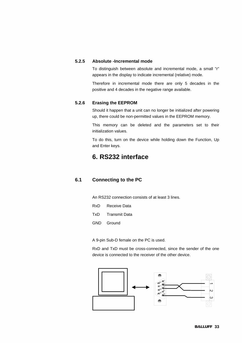
6.1 Connecting to the PC
An RS232 connection consists of at least 3 lines.
RxD Receive Data
TxD Transmit Data
GND Ground
A 9-pin Sub-D female on the PC is used.
RxD and TxD must be cross-connected, since the sender of the one device is connected to the receiver of the other device.
33

6.2 Introduction
The protocol is based on DIN 66019, ISO 1765, ANSI X3.28.
These standards describe a control procedure in the data link of a transmission system.
Only the host unit has the function of the bus master, and the units connected to it are slaves with individual addresses. Slaves are not permitted to send by themselves, but rather only when requested by the master.
There are three call types for communication between master and slave.
• Send
• Receive
• Broadcast
6.3 Technical Data
7-bit ASCII
2400, 4800, 9600, 19200, 38400 baud
1 Stop bit
1 Start bit
1 Parity bit (even)
34

6.4 Functions
Common to the control procedures below is that the transmission control characters specified in the code table per DIN 66 003 are used for data transfer.
The transmission characters are used for determining format, for forward control, backward control, and synchronization.
EOT: Control character (Hex04) End of Transmit AD1: Unit address, high byte AD2: Unit address, low byte STX: Control character (Hex02) Start of Text C1: Parameter code, high byte C2: Parameter code, C3: Parameter code, C4: Parameter code, low byte XXX: Data ETX: Control character (Hex03) End of Text BCC: Block check character ENQ: Control character (Hex05) Enquiry NAK: Control character (Hex15) Not acknowledge ACK: Control character (Hex06) Acknowledge
6.5 Format determination
The transmission character sequence is the format for data transfer. The following transmission control characters are used for indicating the format:
STX: Control character Ctrl B (Hex02) Start of Text
ETX: Control character Ctrl C (Hex03) End of Text
These characters appear only once in the format.
All data are sent in ASCII code.
35

6.5.1 Forward control The following transmission control characters are used by the control station or by the send station for specifying the transmission phases:
EOT: Control character (Hex04) End of Transmit
(end of transmission)
ENQ: Control character (Hex05) Enquiry
(station enquiry)
6.5.2 Backward control Each transmission character sequence, each receive poll and each control command issued to one or more receive stations which does not end the receive state must be confirmed with a reply. The following transmission control characters are used for this:
NAK: Control character (Hex15) Not acknowledge
(negative reply)
ACK: Control character (Hex06) Acknowledge
(positive reply)
36

6.5.3 Data control In the data command the information for activating the parameters, set points and actual values are coded with the axes.
Parameters are implemented as a dual array. All data are handled like parameters. This results in very easy handling of all the data to be managed.
Parameter[Number][Axis]
Each device is modular, and has the character of a slot. There is always a General Level and at least one Axis Level.
The various levels are distributed as follows.
Data command 20XX General Level (calibration value)
Data command 21XX Axis 1
C1,C2
C3,C4
37

6.6 Send
Send transfers data from the master to the slave.
The data string „XXXXXXXX“ may consist of any number of numerical characters and can contain leading zeros as well as a sign. The Block-Check-Character „BCC“ is the exclusive-OR of all characters from "C1 to "ETX“ (all-inclusive)
To prevent the BCC from ending up in the value range of the transmission control characters, Hex20 is added as soon as it is less than Hex20.
If reception was correct, the module answers with "ACK“, and in all other cases with "NAK“.
All parameters sent to the module are first stored in a data buffer. These parameters do not become active until the "activate data" command is sent.
Example:
Send the parameter value P01 100 to a device with Address 11.
The device responds for a display value with "Ack“
EOT AD1 AD2 STX C1 C2 C3 C4 XXXXXXXX ETX BCC
EOT 11 STX 2101 100 ETX BCC
38
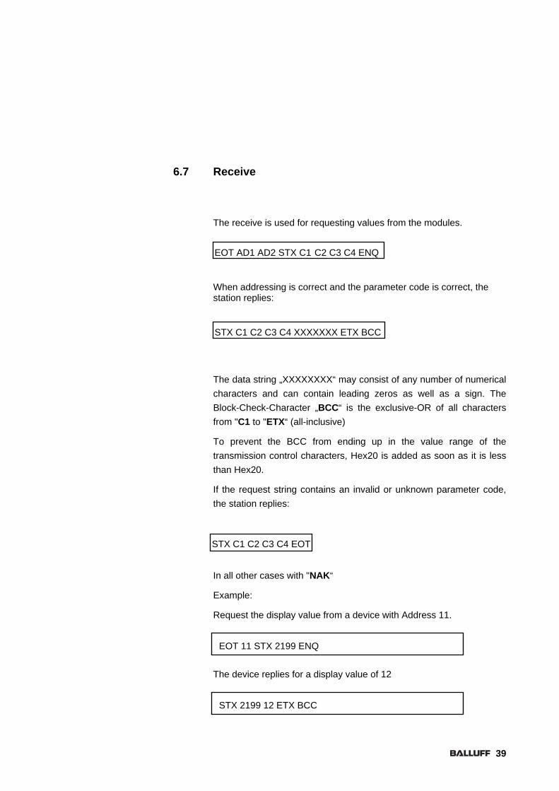
6.7 Receive
The receive is used for requesting values from the modules.
When addressing is correct and the parameter code is correct, the station replies:
The data string „XXXXXXXX“ may consist of any number of numerical characters and can contain leading zeros as well as a sign. The Block-Check-Character „BCC“ is the exclusive-OR of all characters from "C1 to "ETX“ (all-inclusive)
To prevent the BCC from ending up in the value range of the transmission control characters, Hex20 is added as soon as it is less than Hex20.
If the request string contains an invalid or unknown parameter code, the station replies:
In all other cases with "NAK“
Example:
Request the display value from a device with Address 11.
The device replies for a display value of 12
EOT AD1 AD2 STX C1 C2 C3 C4 ENQ
STX C1 C2 C3 C4 XXXXXXX ETX BCC
STX C1 C2 C3 C4 EOT
EOT 11 STX 2199 ENQ
STX 2199 12 ETX BCC
39

6.8 Printer mode
If a printer is connected to the device using an RS232 interface, the following data string is sent cyclically or on demand.
The device sends its address, followed by the actual value, Line Feed and Carriage Return.
Data can be read from the device or written to it even while printer mode is active.
Note however that two transmissions in succession cannot take place, since otherwise erroneous data may be on the bus.
AD1 AD2 ± XXXXXX LF CR
6.9 Serial commands
3 commands can be sent over the serial interface.
1. Activate data, data string number 137
2. Save data in EEPROM, data string number 138
3. Calibrate, data string number 139
Data command 2152 is used to transmit a command.
Example:
Send the Activate data command to a device with Address 11.
EOT 11 STX 2152 138 ETX BCC
40

7. Part Numbering The following variants of the BDD 611 are available:
BDD 611-R4Q4-0-54-N-00:
Supply voltage 115 / 230V AC
No digital outputs
4 digital inputs
No serial port
BDD 611-R3Q4-0-52-N-00
Supply voltage 24V DC/AC
2 digital outputs (transistor output), PNP sourcing
4 digital inputs
No serial port
8. List of Illustrations
Fig. 1 Dimensions (illustration reduced).......................................................... 7
Fig. 2 Wiring diagram....................................................................................... 10
Fig. 3 Front panel ............................................................................................. 15
Fig. 4 Function keys, displays ........................................................................ 32
41

42