b.c. sprinkler irrigation manual - british columbia · sprinkler system design, chapter 5 wheelmove...
TRANSCRIPT
BB..CC.. SSPPRRIINNKKLLEERR IIRRRRIIGGAATTIIOONN MMAANNUUAALL
Chapter 3
Editor
Ted W. van der Gulik, P.Eng. Senior Engineer
Authors
Stephanie Tam, P.Eng. Water Management Engineer
Andrew Petersen, P.Ag.
Regional Resource Specialist
Prepared and Web Published by
Ministry of Agriculture
2014 ISSUE
LIMITATION OF LIABILITY AND USER’S RESPONSIBILITY
The primary purpose of this manual is to provide irrigation professionals and consultants with a methodology to properly design an agricultural irrigation system. This manual is also used as the reference material for the Irrigation Industry Association’s agriculture sprinkler irrigation certification program. While every effort has been made to ensure the accuracy and completeness of these materials, additional materials may be required to complete more advanced design for some systems. Advice of appropriate professionals and experts may assist in completing designs that are not adequately convered in this manual. All information in this publication and related materials are provided entirely “as is” and no representations, warranties or conditions, either expressed or implied, are made in connection with your use of, or reliance upon, this information. This information is provided to you as the user entirely at your risk. The British Columbia Ministry of Agriculture and the Irrigation Industry Association of British Columbia, their Directors, agents, employees, or contractors will not be liable for any claims, damages or losses of any kind whatsoever arising out of the use of or reliance upon this information.

Chapter 3 Irrigation System Selection 21
3 IRRIGATION SYSTEM SELECTION There are several types of irrigation systems that can be used to apply water to agricultural crops. Each type of system has its own advantages and disadvantages. Some may be less expensive but may require more labour to move around and/or have lower system application efficiencies. The more expensive systems may have higher capital costs but can save money over time by having lower operating costs through reduced labour requirements and/or better operating efficiencies. Often, system selection is determined by the shape of the field and the type of crop being grown. Certain types of systems require larger fields to be cost effective. Others work better on flat fields and will not operate to designed efficiencies on uneven fields. Table 3.1 shows the typical application efficiencies of all sprinkler irrigation system types.
The five main types of agricultural irrigation systems are Sprinkler Systems, Stationary Gun Systems, Travelling Gun Systems, Centre Pivot Systems and Trickle Systems. Trickle systems will not be covered in this manual. A separate manual has been prepared for trickle irrigation design. B.C. Trickle Irrigation Manual
Table 3.1 Typical Application Efficiencies of Sprinkler Irrigation Systems
Irrigation System Type Typical Application Efficiency [%]
Sprinklers Handmove 72
Wheelmove 72
Overtree Solid Set 70
Undertree Solid Set 75
Micro-sprinklers 80
Guns Stationary 58
Travelling 65
Centre Pivot Sprinklers 72
Spray Heads 72
Drop Tube Rotors 80

22 B.C. Sprinkler Irrigation Manual
3.1 Sprinkler Systems Sprinkler irrigation systems include handmove and wheelmove systems, undertree and overtree solid set systems and micro-sprinkler systems which are usually also solid set.
Handmove System
A handmove system consists of aluminum piping which is moved by uncoupling the lateral lines and manually transferring the pipes to the next set. Lateral line sizes of 2-inch and 3-inch aluminum are normally used. Lateral pipe lengths are usually 30 or 40 feet long. Each lateral pipe usually contains one sprinkler; therefore, sprinkler spacing along the lateral will often be 30 or 40 feet. Figure 3.1 shows a typical handmove system.
Handmove systems originated in the 1950’s and are very labour intensive. However, this system is still being used today in older orchards and pastures and is often used to irrigate corners of odd-shaped fields that are not covered by a travelling gun or centre pivot. Sprinkler System Design, Chapter 5
Wheelmove System
On larger alfalfa and forage fields, many handmove systems have been replaced by wheelmove systems to reduce labour requirements. A wheelmove system consists of 4-inch or 5-inch aluminium pipe that is attached to wheels. Figure 3.2 shows an example of a wheelmove system. Heavier gauged aluminum pipe is used as the lateral pipe must also act as an axle. Figure 3.3 shows a powered mover which is usually situated in the centre of the lateral and rolls the lateral ahead when the system is shut down. The lateral remains stationary when the irrigation system is in operation. It can only be moved after the line has been shutdown and drained. Drain ports are installed on each pipe to allow the line to drain automatically when water is turned off. The drain ports close when the shutoff valve is opened and the lateral line is pressurized.
Sprinklers are usually spaced 40 feet along the wheelline with one sprinkler per pipe section. Sprinkler spacing can be adjusted as required with spacings ranging from 30 to 60 feet. Self levellers are recommended, especially on sprinklers located further away from the mover, to ensure that the sprinkler heads remain upright. Wheelmoves should be no longer than 1,500 feet in length as longer lengths make it difficult to advance the system. Wheel sizes can vary from 5 to 7 feet, depending on crop growth height. The circumference of the wheel usually coincides with lateral spacings of 60 feet, that is, an even number of complete revolutions of the wheel will be 60 feet. Mainline lengths are usually 30 feet which allows the hydrant locations to match the wheelmove spacing. Sprinkler System Design, Chapter 5
Figure 3.2 Wheelmove System
Figure 3.1 Handmove System
Figure 3.3 Powered Mover

Chapter 3 Irrigation System Selection 23
Sprinkler Solid Set System
A solid set system is usually a permanent sprinkler installation, consisting of above or below ground piping. The sprinklers are located at permanent positions and are not moved. Unlike handmove and wheelmove systems, which are usually designed in denominations of 30 or 40 feet to accommodate aluminum pipe lengths, solid set spacings can be adjusted to match tree or vine plantings if buried PVC pipes are used. For a tree spacing of 8 feet, the sprinkler spacing on a lateral may be as wide as 32 feet. For above ground solid set systems, aluminium pipe is most often used but the sprinkler spacing is then usually 30 or 40 feet.
Solid set systems may be either overtree or undertree depending on the length of risers used. Solid set systems are common in orchards, vineyards and berry plantings. Overtree systems generally have larger sprinkler spacings than undertree systems and therefore require larger sprinklers with higher flow rates and operating pressures. Overtree systems are often used whenever the crop will interfere with an undertree system. Undertree systems are more common however and have the advantage of keeping the foliage dry when the irrigation system is operating, reducing crop diseases. Where tree fruits and other horticultural crops have been pulled out, it is not uncommon to see solid set systems on pasture or alfalfa fields because the systems were originally designed for use on horticultural crops. Figures 3.4 and 3.5 illustrate both types of solid set sprinkler systems. Sprinkler System Design, Chapter 5
Micro-Sprinkler System
Micro-sprinklers are another type of solid set system. A micro-sprinkler system is mostly used in orchards and nurseries. The micro-sprinklers are often placed between the plants and on every row as the wetted diameter is much less than in sprinkler systems. The overall number of sprinklers required on a per acre basis is therefore also much higher. Due to the small droplet size, micro-sprinklers are usually installed undertree. Wind drift on overtree systems would be too high. Micro-sprinkler flow rates are higher than spray emitters used in trickle irrigation but are still often less than one gallon per minute. The lateral pipe used is either buried PVC or above-ground polyethylene. Micro-sprinkler systems use the same design principles as other sprinkler systems. Figure 3.6 shows a close-up of a micro-sprinkler. Sprinkler System Design, Chapter 5
3.2 Gun Systems In agricultural irrigation, the term gun is used to describe high volume sprinklers with discharge rates exceeding 40 US gpm. Flow rates for a gun can go as high as 1,000 US gpm but normally the larger guns in British Columbia are around 300 US gpm. There are two types of gun systems: Stationary Gun and Travelling Gun.
Figure 3.5 Undertree Solid Set System
Figure 3.6 Micro-Sprinkler System
Figure 3.4 Overtree Solid Set System

24 B.C. Sprinkler Irrigation Manual
Stationary Gun System
Stationary guns are usually operated from a tripod or a stand on wheels. These systems are moved by hand from one location to another. Water is usually supplied to the gun by above ground aluminum pipes or buried PVC pipe with hydrants at strategic locations. Operating pressures may range from 40 to 130 psi depending on the gun and type of nozzle selected. Figure 3.7 shows an example of a stationary gun system.
Gun nozzles are available in a variety of sizes and trajectory angles. The trajectory angle is important in determining maximum spray height and distance of throw. Gun systems can utilize two types of nozzles: taper bore or ring nozzles. Taper bore nozzles provide better stream integrity and create maximum distance of throw with less distortion due to wind. Ring nozzles provide better stream break up and offer greater choice in nozzle sizes.
Stationary Gun systems can be purchased in four different series or sizes. The smallest guns, Series 75 should be operated with nozzle sizes ranging from 0.5 to 0.8 inches at operating pressures from 40 to 80 psi. Flow rates are then generally between 40 and 150 gpm. The Series 100 gun can be operated with nozzles ranging from 0.5 to 1.0 inches at operating pressures from 40 to 110 psi. Flow rates will generally be between 40 and 300 gpm.
The medium range gun size (Series 150) can utilize nozzles from 0.7 to 1.4 inches at operating pressures from 50 to 120 psi. Discharge rates are typically from 100 to 500 US gpm.
The largest gun (Series 200) uses nozzles from 1.0 to 2.0 inches at operating pressures from 60 to 130 psi. Discharge rates are typically 250 to 1,000 US gpm. Gun System Design, Chapter 6
Helpful Tips – Stationary Gun Use
For most cases in B.C., the 75, 100 and 150 series gun sizes are used for agricultural applications.
Stationary gun systems have low efficiencies and high application rates. It is difficult to operate the system to match the crop and soil type present. The maximum set time for a stationary gun is usually 4 to 6 hours. Stationary guns are not recommended where inefficient use of irrigation water is a concern.
Travelling Gun System
Travelling gun systems overcome the problem of the short set time generally required with stationary gun designs. The travelling gun system also allows for large parcels of land to be irrigated during one irrigation set. Flow rates generally range from a minimum of 75 US gpm up to 700 US gpm. For agricultural irrigation purposes in B.C., travelling gun systems in the 150 to 350 US gpm range are most often used.
There are two types of travelling gun machines: the water winch (or soft hose traveller) and the hose reel (or hard hose traveller).
Figure 3.7 Stationary Gun System
Chapter 3 Irrigation System Selection 25
Water Winch or Soft Hose Traveller
The water winch machine travels by use of a cable anchored at the end of the field. The hose is dragged behind as the machine is winched in along the cable. The hose is flexible so it can be easily rewound onto a hose reel for transport after completing its run. However, the major drawback is that the soft hose is easily damaged by dragging. While some of these systems may still be found, they are no longer sold as they have been replaced by the hose reel system.
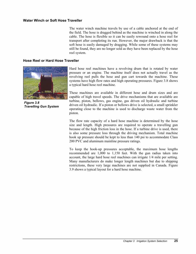
Hose Reel or Hard Hose Traveller
Hard hose reel machines have a revolving drum that is rotated by water pressure or an engine. The machine itself does not actually travel as the revolving reel pulls the hose and gun cart towards the machine. These systems have high flow rates and high operating pressures. Figure 3.8 shows a typical hard hose reel machine.
These machines are available in different hose and drum sizes and are capable of high travel speeds. The drive mechanisms that are available are turbine, piston, bellows, gas engine, gas driven oil hydraulic and turbine driven oil hydraulic. If a piston or bellows drive is selected, a small sprinkler operating close to the machine is used to discharge waste water from the piston.
The flow rate capacity of a hard hose machine is determined by the hose size and length. High pressures are required to operate a travelling gun because of the high friction loss in the hose. If a turbine drive is used, there is also some pressure loss through the driving mechanism. Total machine hook up pressure should be kept to less than 140 psi to accommodate Class 200 PVC and aluminum mainline pressure ratings.
To keep the hook-up pressures acceptable, the maximum hose lengths recommended are 1,000 to 1,150 feet. With the gun radius taken into account, the large hard hose reel machines can irrigate 1/4 mile per setting. Many manufacturers do make longer length machines but due to shipping restrictions, these very large machines are not supplied in Canada. Figure 3.9 shows a typical layout for a hard hose machine.
Figure 3.8 Travelling Gun System

26 B.C. Sprinkler Irrigation Manual
Figure 3.9 Hard Hose Reel Machine Layout
Hard hose machines are also often used for applying manure. A small engine is then coupled to the drive train to prevent the turbine or piston drive from becoming plugged. Most machines can also be reeled in using the power take-off (PTO) tractor. Travelling Gun Design, Chapter 6
3.3 Centre Pivot System A center pivot system consists of a single lateral, supported by trusses and towers on wheels, with one end anchored to a fixed pivot structure and the other end free to move in a circle about the pivot point. The span between drive towers ranges from 120 to 215 ft. Standard span systems of 125 to 130 ft are usually designed to take the stresses of slopes up to 30%. Long span systems of 170 to 215 feet between towers can effectively irrigate slopes up to 15%. Long span systems are less expensive than standard span systems as fewer drive train components and controls are required. Center pivot laterals can vary in length from 200 to 2,600 feet depending on span lengths and number of towers used. An end gun shown in Figure 3.10 is usually used on the overhang of the last tower to increase the effective wetted radius of the center pivot. Figure 3.11 shows the centre pivot components.
Figure 3.10 Pivot End Gun

Chapter 3 Irrigation System Selection 27
Figure 3.11 Centre Pivot Components
Centre pivot systems can be powered by an electric motor drive, hydraulic oil drive or hydraulic water drive. The most common type of drive mechanism in the industry is electric. There are a limited number of older water drive units in B.C. but the new water drives are for a single tower pivot only. Electric motor drive units include 1/4, 1/2, 3/4, 1 and 1 1/2 hp motors, selected according to the rotation speed required and the type of gearbox used. The motor is coupled to a reduction gearbox at the centre of each drive unit with drive shafts extending to reduction final drives at each wheel.
The ratio at which the drive unit and lateral pipe advance about the pivot point is determined by the speed of the outermost drive unit. Alignment devices detect misalignment of any drive unit and start the motor on that tower. The tower then drives forward or reverses depending on direction selected. Since it has less distance to go than the next tower, it catches up and is shut off by the alignment switch. Therefore, the advancement of the outermost drive unit starts a series of advances by each drive unit, starting with the second unit from the outer end and progressing along the lateral to the pivot point. If any drive unit becomes too far out of alignment, a safety device shuts down the system to prevent damage to the lateral.
Full circle and part circle centre pivots are installed in British Columbia. All
PUMP HOUSE
SPRINKLER
TRUSS
CONTROLS
PIVOT POINT
FIRST TOWER

28 B.C. Sprinkler Irrigation Manual
electric pivots will reverse. The part circle units often have an automatic stop-and-reverse mechanism that is signalled by a tower barricade positioned in the path of the last tower.
Pivot systems are controlled in a number of ways. The most basic is a percentage timer that controls how long the end tower drives in one minute period. The most advanced pivots use full computer control. GPS units can speed up the pivot over heavy soils, connect to weather stations and soil moisture controls. With most pivots that have a controller a depth to apply can be selected. Common depths are ¼, ½ and ¾ inch. This of course would depend on the ability of the soil to infiltrate the water. Centre Pivot Design, Chapter 7
Centre Pivot Sprinkler Selection
Centre pivot systems can utilize a number of different sprinkler configurations to accommodate crop, soil type and terrain. Figure 3.12 illustrates the different types of water patterns. An end gun is generally used with all system types to increase the wetted radius of the pivot. A booster pump on the end tower is used for the gun if the pressure is not sufficient.
Large Sprinklers
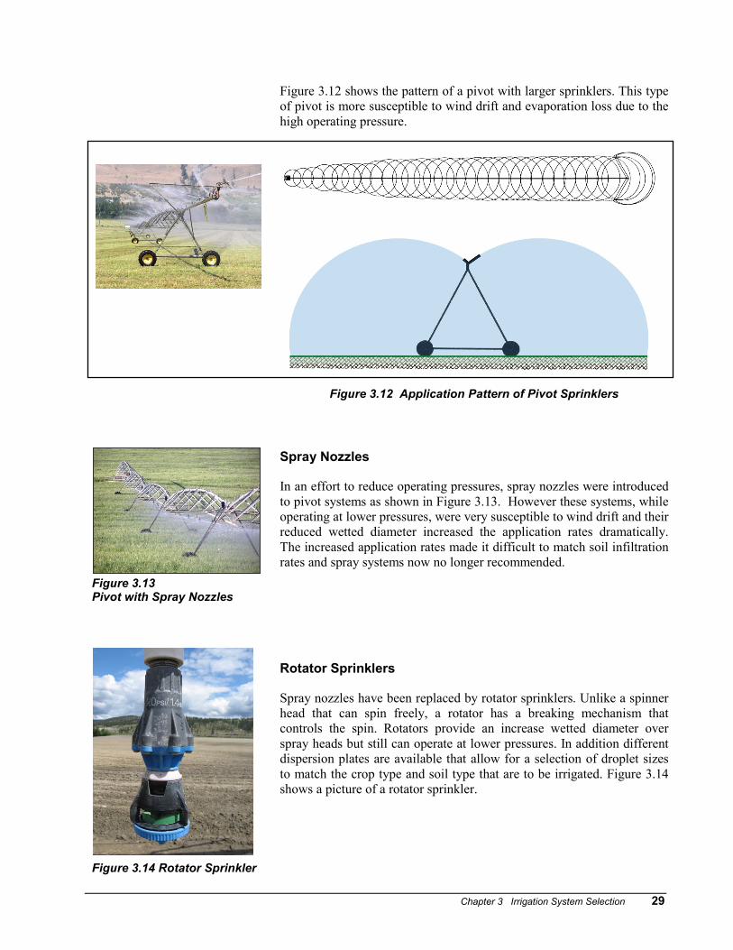
Older centre pivots often use different sized sprinklers that increase in size along the lateral out from the pivot point. The sprinkler flow rate near the pivot point is much less than sprinklers located near the end tower. Each successive sprinkler must put out more volume to maintain uniform application along the lateral. Sprinkler operating pressures may be as high as 70 psi with a wetted diameter of 80 ft or more for the larger sprinklers. This type of centre pivot is well suited for rough terrain and soils with low infiltration rates. If operated properly, this type of pivot is also less susceptible to wind drift and evaporation loss. Figure 3.12(a) shows a typical centre pivot with larger sprinklers.
Variable Spaced Sprinklers
For variable spaced sprinklers, approximately the same size sprinklers are used along the entire lateral. The sprinkler spacing decreases from the pivot point to the end of the lateral. Therefore, the number of sprinklers per foot of lateral at the end of the pivot is much higher than at the pivot point. This type of system has a slightly lower operating pressure than the larger sprinkler system and also has smaller droplets which reduce soil compaction. Two types of variable spaced impact sprinklers are available:
a. Single nozzle impact sprinklers with a minimum operating pressure of 45 psi.
b. Low pressure double nozzle sprinklers with a minimum operating pressure of 35 psi.
Chapter 3 Irrigation System Selection 29
Figure 3.12 shows the pattern of a pivot with larger sprinklers. This type of pivot is more susceptible to wind drift and evaporation loss due to the high operating pressure.
Figure 3.12 Application Pattern of Pivot Sprinklers
Figure 3.13 Pivot with Spray Nozzles
Figure 3.14 Rotator Sprinkler
Spray Nozzles
In an effort to reduce operating pressures, spray nozzles were introduced to pivot systems as shown in Figure 3.13. However these systems, while operating at lower pressures, were very susceptible to wind drift and their reduced wetted diameter increased the application rates dramatically. The increased application rates made it difficult to match soil infiltration rates and spray systems now no longer recommended. Rotator Sprinklers
Spray nozzles have been replaced by rotator sprinklers. Unlike a spinner head that can spin freely, a rotator has a breaking mechanism that controls the spin. Rotators provide an increase wetted diameter over spray heads but still can operate at lower pressures. In addition different dispersion plates are available that allow for a selection of droplet sizes to match the crop type and soil type that are to be irrigated. Figure 3.14 shows a picture of a rotator sprinkler.

30 B.C. Sprinkler Irrigation Manual
Rotator heads are usually installed with drop tubes as shown in Figure 3.15. The configuration is similar to sprinklers in that the size of the rotator increases along the pivot and the spacing of the rotators decrease, increasing the number of rotators per unit length of pivot towards the end of the pivot.
Rotators are also used in the nursery industry. Rotary nozzle sizes can be found in Chapter 7. Centre Pivot Design, Chapter 7
Figure 3.15 Application Pattern of Rotator Sprinklers
Centre Pivot Layout
Center pivots are able to operate in various shaped fields by turning the end gun on and off, using a tower that can swing out where necessary or limiting the arc of the pivot itself. Figure 3.16 shows a pivot that is operating as a ¾ circle and has the end gun turning on only in the corners.

Chapter 3 Irrigation System Selection 31
Figu
re 3
.16

32 B.C. Sprinkler Irrigation Manual
(BLANK)