bc hydro real time operations operating order 7t 18 bc - us interconnection · pdf...
TRANSCRIPT

BC HYDRO
REAL TIME OPERATIONS
OPERATING ORDER 7T – 18
BC - US INTERCONNECTION Supersedes 7T-18 issued 22 October 2015
Effective Date: 15 December 2015 Review Year: 2019
Original signed by: APPROVED BY:
Paul Choudhury General Manager, Real Time Operations
Denotes Revision

OO 7T-18 Effective Date: 15 December 2015
Page 2 of 44
CONTENTS
1.0 DESCRIPTION ..............................................................................................................................................4 1.1 General .............................................................................................................................................4 1.2 Circuit Boundaries ............................................................................................................................5 1.3 Communication .................................................................................................................................5 1.4 Safety Protection...............................................................................................................................5 1.5 Equipment Rating .............................................................................................................................5 1.6 Operating Procedures to Support Peak RC .....................................................................................6
2.0 AUTO RECLOSING ......................................................................................................................................6
3.0 LOOP CLOSURE / SYNCHRONIZING .........................................................................................................6
4.0 VOLTAGE CONTROL SCHEMES ................................................................................................................7 4.1 Reactive Power Remedial Action Scheme (Rx Ras) .......................................................................7
4.1.1 Purpose ...................................................................................................................................7 4.1.2 Operation .................................................................................................................................7
4.1.3 Coordination with Auto-VAR Schemes .............................................................................................7 4.2 Direct Transfer Tripping of 5L83 .......................................................................................................8
5.0 EASTERN CONTROLLED SEPARATION REMEDIAL ACTION SCHEME (ECS RAS) .............................9 5.1 ECS RAS Description .......................................................................................................................9 5.2 ECS RAS at NLY Requirement when 2L277 is connected to NLY ...................................................9 5.3 ECS RAS Operation Due to Loss of Custer-Monroe #1 and #2 500kV Circuits ...............................9
6.0 ALBERTA TIE TRIPPING REMEDIAL ACTION SCHEME (AB TIE RAS) ................................................10 6.1 Description ......................................................................................................................................10 6.2 AB TIE RAS Arming for imports from Alcan and US ......................................................................11
7.0 5L61 TRIPPING REMEDIAL ACTION SCHEME (5L61 RAS) ...................................................................11 7.1 Description ......................................................................................................................................11 7.2 5L61 RAS Arming for Imports from US and Alcan .........................................................................12
.8.0 SYSTEM OPERATING LIMITS (TRANSFER LIMITS) ...............................................................................12 8.1 General ...........................................................................................................................................13 8.2 Corrective Measure when Transfer Limits Are Exceeded ..............................................................13 8.3 System Requirements for BC Exporting to US ...............................................................................13
8.3.1 5L51 or 5L52 Thermal Limit vs. Ambient Temperature at ING..........................................13 8.3.2 On-line Equivalent Burrard Synchronous Condensers (Attachment 3) .............................13 8.3.3 Increasing the ING to CUS transfer above 2000 MW .......................................................14 8.3.4 Operating Guidelines and Restrictions ..............................................................................17 8.3.5 (5L83 AND 5L87 AND 5L71 OOS) or (5L83 AND 5L87 and 5L72 OOS) ..........................18 8.3.6 NTL Tie O.O.S. ..................................................................................................................18 8.3.7 5L44 Contingency ..............................................................................................................18 8.3.8 5L71 or 5L72 O.O.S with One MCA Unit On-Line .............................................................18
8.4 BC to US Transfer Limits (Export from BCH System) ....................................................................18 Table A1 - ING to CUS Transfer Limits for System Normal, N-1 or N-2 system status .................20 Table A2 - ING to CUS Transfer Limits for 5L83 AND Other Line/Equipment O.O.S ....................21
8.5 System Requirements for BC Importing from US ...........................................................................22 8.5.1 5L51 or 5L52 Thermal Limit versus Ambient Temperature at Ingledow ............................22 8.5.2 (5L83 AND 5L87 AND 5L71 OOS) or (5L83 AND 5L87 AND 5L72 OOS) ........................22 8.5.3 NTL Tie O.O.S. ..................................................................................................................22 8.5.4 Operating Guidelines and Restrictions ..............................................................................22 8.5.5 5L71 or 5L72 O.O.S with One MCA Unit On-Line .............................................................22
8.6 US-BC Transfer Limits (Import into BCH System) ........................................................................23 Table B1 – CUS to ING Transfer Limits for System Normal, N-1 or N-2 system status ................24 Table B2 – CUS to ING Transfer Limits for 5L83 AND Other Line/Equipment O.O.S ...................25
9.0 GENERATOR SHEDDING ..........................................................................................................................26 9.1 Initiation...........................................................................................................................................26 9.2 Allocation ........................................................................................................................................27 9.3 Shedding for: Loss of “5L51 AND 5L52”, or Loss of 5L51 (or 5L52) with 5L52 (or 5L51) O.O.S. ..28
9.3.1 All system conditions except 2L112 O.O.S., or 5L92 O.O.S., or 5L94 O.O.S., or (5L94

OO 7T-18 Effective Date: 15 December 2015
Page 3 of 44
AND 5L96) O.O.S.: .........................................................................................................................28 9.3.2 2L112 O.O.S. : ...................................................................................................................28 9.3.3 5L92 O.O.S.: ......................................................................................................................28 9.3.4 5L94 O.O.S. or 5L94 AND 5L96 O.O.S.: ...........................................................................28
9.4 Shedding For Loss of 5L51 With Both 5L51 AND 5L52 In Service ................................................28 9.5 Shedding For Loss of 5L52 With Both 5L51 AND 5L52 In Service ................................................29 9.6 Shedding for Loss of Pacific Northwest Circuits (BPA/NW RAS) ...................................................29 9.7 Shedding for Loss of an Element(s) of the U.S. 500 kV Pacific AC Intertie (BPA/PACI RAS) .......30
10.0 AUTOMATIC GENERATION CONTROL (AGC) SUSPENSION ..............................................................30
11.0 TSA-PM IMPLEMENTATION ....................................................................................................................31
12.0 REVISION HISTORY .................................................................................................................................34
ATTACHMENT 1: 5L51 OR 5L52 THERMAL LIMIT VERSUS AMBIENT TEMPERATURE AT ING ..........37
ATTACHMENT 2: ING-CUS TRANSFER LIMITS FOR ALL SYSTEM CONDITIONS .................................38 1. ING to CUS transfer Limit ...............................................................................................................38
All system conditions except 5L51 or 5L52 O.O.S.: .......................................................................38 5L51 or 5L52 O.O.S.: ......................................................................................................................38
2. CUS to ING Transfer Limit ..............................................................................................................39 All system conditions except for 5L51 or 5L52 O.O.S.: ..................................................................39 5L51 or 5L52 O.O.S: .......................................................................................................................39
ATTACHMENT 3: ING TO CUS TRANSFER LIMIT VERSUS BCH LOAD AND NUMBER OF ON-LINE EQUIVALENT BURRARD SYNCHRONOUS CONDENSERS (ALL SYSTEM CONDITIONS) ..............40
ATTACHMENT 4: ING TO CUS TRANSFER VERSUS BC-ALBERTA TRANSFER (SYSTEM
NORMAL ..........................................................................................................................................41
) (NOTE 1) ..........................................................................................................................................................41
ATTACHMENT 5: ING TO CUS TRANSFER VERSUS BC-ALBERTA TRANSFER (2L112 OOS OR 5L83 AND 2L112 OOS) ......................................................................................................................................42
ATTACHMENT 6: ING TO CUS TRANSFER VERSUS BC-ALBERTA TRANSFER (2L293 OOS OR 5L83 AND 2L293 OOS) ......................................................................................................................................43
ATTACHMENT 7: ING TO CUS TRANSFER VERSUS BC-ALBERTA TRANSFER (5L91 OOS OR 5L83 AND 5L91 OOS) ........................................................................................................................................44
OO 7T-18 Effective Date: 15 December 2015
Page 4 of 44
1.0 DESCRIPTION 1.1 General
This Operating Order describes the operation of the BC-US Interconnection, also defined as Path 3 in the WECC Path Rating Catalog. Documented in this order are the general operating requirements, responsibilities for entities associated with the Interconnection, voltage control and switching requirements, Synchronizing, and special operating configuration requirements. Also provided in this order are the BC Hydro (BCH) System Operating Limits (SOL) and Remedial Action Scheme (RAS) arming requirements for the BC–US Interconnection. The SOL and RAS Arming requirements for the BC–US Interconnection can be found in sections 8 and 9, and supporting attachments. These limits cover the worst case operating conditions. Variations from these limits and arming conditions will be provided through additional Operating Plans, for specific operating conditions on a case basis. Operating Plans are engineered to support outages and short term operating requirements, superseding as necessary any requirements in this order. The BC-US Interconnection (WECC Path 3) is defined as:
One 500 kV circuit (designated 5L51 within BC Hydro operating area and Custer-Ingledow 500 kV cct #1 within BPA operating area) between BC Hydro’s Ingledow substation (ING) and BPA’s Custer substation (CUS). The path metering is at Ingledow.
One 500 kV circuit (designated 5L52 within BC Hydro operating area and Custer-Ingledow 500 kV cct #2 within BPA operating area) between BC Hydro’s Ingledow substation (ING) and BPA’s Custer substation (CUS). The path metering is at Ingledow.
One 230 kV circuit (designated 2L112 within BC Hydro operating area and Boundary-Nelway 230 kV circuit within BPA’s operating area) between BC Hydro’s Nelway substation (NLY) and Boundary Substation in the BPA operating area. The path metering is Boundary.
One 230 kV circuit (designated 71L within the BC Hydro operating area and designated Boundary-Waneta 230 kV cct within the BPA operating area) between Fortis BC’s Waneta Generating Station and Boundary Generating station in the BPA operating area. The path metering is at Boundary. This circuit is Normally Open, and cannot be operated in parallel with other interconnection lines for the present implemented RAS schemes.
The circuits between Ingledow and the international border will be known within BCH as 5L51 and 5L52. However, when communicating with BPA these lines will be referred to as the “Custer - Ingledow 500 kV Line 1” and “Custer - Ingledow 500 kV Line 2” respectively. These circuits are also collectively referred to Path 3 “West Side”. The circuit between Nelway and the international border will be known within BCH as 2L112, however when communicating with BPA will be referred to as the "Boundary-Nelway 230 kV line". This circuit together with the Nelway 230 kV Phase Shifting Transformer (PST) may also be referred to as Path 3 “East Side”. BC Hydro Control Centre (BCHCC) and BPA's Dittmer Control Centre will coordinate all trouble dispatch by mutual agreement depending upon the circumstances. Each utility will apply its own patrol procedures and policies, and will operate according to its own operating rules up to the point of interconnection.
Both BPA and BCHCC Operators must be notified of any plans or actions affecting the operation of the interconnection.
OO 7T-18 Effective Date: 15 December 2015
Page 5 of 44
1.2 Circuit Boundaries Circuits 5L51 and 5L52 and 2L112 connect the B.C. Hydro Integrated System to the American part of the Northwest Power Pool (NWPP). Each 500 kV circuit runs 22 km from Ingledow Substation to the international border and extends 14 km to the BPA Custer station:
5L51 structure 13-4 is in B.C. Hydro’s Lower Mainland division.
5L52 structure 13-4 is in B.C. Hydro’s Lower Mainland division.
Circuit 2L112 (the Boundary to Nelway transmission line) is approximately 4.0 km long with the BPA Boundary Substation situated south of the Canada - U.S.A. international boundary, and Nelway Substation on the north. At the Nelway terminal, a phase shifting transformer (with a bypass) forms part of the 2L112 circuit.
1.3 Communication
BCHCC and BPA Dittmer CC: Dispatch Intercom and DATS phone.
1.4 Safety Protection NWPP Terminology:
“Terminal Hold” may be used instead of “Guarantee of No Reclose” “Terminal Clearance” may be used instead of “Guarantee of Isolation”.
A Clearance on circuit 5L51, 5L52 or 2L112 will be issued by the Grid Desk Operator after a Guarantee of Isolation (Terminal Clearance) is obtained from the BPA Dispatcher via the Transmission Coordinator. A Live Line Permit on circuit 5L51, 5L52 or 2L112 will be issued by the Grid Desk Operator after a Guarantee of No Reclose (Terminal Hold) is obtained from the BPA Dispatcher via the Transmission Coordinator. Similarly, the BPA Dispatcher may ask BCH for a Guarantee of Isolation (Terminal Clearance or a Guarantee of No Reclose (Terminal Hold) on these circuits. For a Guarantee of Isolation (Terminal Clearance), the Grid Desk Operator will issue a GOI to the BPA Dispatcher via the Transmission Coordinator. The Transmission Coordinator will log the GOI # and communicate the GOI (Terminal Clearance) information to the BPA Dispatcher. For a Guarantee of No Reclose (Terminal Hold), the Grid Desk Operator will issue a GNR to the BPA Dispatcher via the Transmission Coordinator. The Transmission Coordinator will log the GNR and communicate the GNR (Terminal Hold) information to the BPA Dispatcher.
1.5 Equipment Rating
At Ingledow Substation (ING), the current transformers for 5L51 and 5L52 circuits are rated at 3000 A continuously and 3300 A for 30 minutes. The continuous current rating of 5L51 is:
3334 A at 20 degree C ambient temperature,
2992 A at 30 degree C ambient temperature, and
2483 A at 40 degree C ambient temperature. The continuous current rating of 5L52 is:
3328 A at 20 ºC ambient temperature,
2992 A at 30ºC ambient temperature, and

OO 7T-18 Effective Date: 15 December 2015
Page 6 of 44
2521 A at 40 ºC ambient temperature.
Refer to Operating Order 5T-10 for their detailed sources. Attachment 1 has chart showing the continuous current and MW ratings of 5L51 or 5L52 based on the round off ratings of 5L51 and the 30-minute rating of ING CT (3300 A) at various ambient temperatures.
1.6 Operating Procedures to Support Peak RC BC Hydro Operators may be called upon in real time to take actions to support the Peak RC Operating Procedure for the North West Washington (NW WA) Area Net Load Limit IROL. Under heavy loads and certain major 500 kV line outage conditions, the NW WA Load Area may experience voltage instability under identified contingencies in the plan. BPA and Peak RC monitor the loading and the voltage stability limit, and as margin between the load and limit decrease, the Peak RC procedure requires consultations and actions in a prescribed plan. BC Hydro may be called upon to take actions under the plan that includes:
Removing RX and inserting shunt CX to reduce VAR flow into the BCH system, while maintaining BCH voltages within operating limits, and
Moving S-N flow from the West Side of Path 3 to the East Side if beneficial to reduction in VAR depletion, and
Considering a reduction in interruptible energy schedules flowing S-N on Path 3 “West Side” during an alert stage.
Firm energy interruption if beneficial to reducing S-N flows on Path 3 “West Side”, when firm curtailments are implemented in the NW WA area
A copy of the plan shall be kept in the BCH Control Centre for use by the Transmission Coordinator, the RT Ops Engineer, and the System Control Manager. For more detailed information roles and responsibilities in the procedure, see the control room copy titled, “Peak Reliability - Monitoring NW Washington Net Load Limit IROL Procedure”.
2.0 AUTO RECLOSING 5L51 and 5L52 auto-reclosing lead end is Custer and follow end is Ingledow. It is supervised by return of voltage potential and parallel line current supervision at the ING slave end. There is no auto-reclosing available on 2L112.
3.0 LOOP CLOSURE / SYNCHRONIZING 5L51 and 5L52 closing angle at ING is supervised by a synchro-verifier set at 30 degrees for 10 seconds. If synchronism is maintained through Boundary Substation (BDY), the ING closing angle should be reduced by reducing 2L112 MW transfer to zero by setting the Nelway phase shifter at tap 17. An angle greater than 30 degrees could occur due to power flow patterns in the BPA system. However, the ING closing angle can then be reduced to 30 degrees or less by adjusting the Nelway phase shifter. The circuits 5L51 and 5L52 will normally be energized from Custer and synchronized at Ingledow. The circuit 2L112 is normally energized from Boundary and synchronized closed at Nelway but this may be reversed as required. See Operating Order 7T-33 for further details. Local manual and supervisory automatic synchronizing is available at Nelway; only local manual synchronizing is available at Boundary. All 230 kV circuit breakers at Nelway have synchronizing control. For the synchronizer to work, some slip (maximum 0.20 hertz) must exist across the circuit breaker. A synchro-check relay has also been provided to allow closing of the circuit breaker when no slip exists across it. If the bus on either side of

OO 7T-18 Effective Date: 15 December 2015
Page 7 of 44
the circuit breaker is de-energized then sync bypass must be used to close the circuit breaker via supervisory control. Phase angle telemetering has been provided at Nelway. The reading from this device will only be accurate if both sides of the selected circuit breaker are energized. The synchro-check relay will allow the circuit breaker to close if the angle across the circuit breaker is 15 degrees or less.
4.0 VOLTAGE CONTROL SCHEMES Voltage controls schemes are used to manage system voltages within normal operating limits pre and post contingency, to support interconnection transfers. These schemes are located at KLY, ING, NIC, MDN, ACK and SEL, and involve the Reactive Power Remedial Action Scheme (RX RAS), local Auto-VAR schemes and circuit Direct Transfer Tripping (DTT) for 5L83. 4.1 Reactive Power Remedial Action Scheme (Rx Ras)
4.1.1 Purpose
The Reactive Power Remedial Action Scheme (RX RAS) was designed to reduce high voltages in the BC Hydro system for loss of 5L51 and 5L52 when the Ingledow to Custer (CUS) transfer exceeds 2000 MW. RX RAS has six components:
RX RAS at KLY
RX RAS at NIC
RX RAS at ING
RX RAS at MDN
RX RAS at ACK
RX RAS at SEL
4.1.2 Operation
Arm the RX RAS if the ING to CUS transfer > 2000 MW. The BCH EMS Transient Stability Analysis (TSA-PM) advanced application normally arms/disarms the RX RAS. The BCH Transmission Coordinator is responsible to arm and disarm the RX RAS. When TSA-PM is unavailable, the operator can manually arm/disarm the RX RAS from the EMS Generation Shedding Display. With the RX RAS armed and upon the loss of 5L51 and 5L52, the RX RAS will:
Switch out in-service shunt capacitors:
Ingledow 2CX11, 2CX2, 2CX31 and 2CX32
Meridian 2CX1, 2CX2, 2CX3 and 2CX4
Ashton Creek 5CX1 and 5CX2 (each of ACK 5CX1 and 5CX2 has individual arming/disarming facility)
Switch in shunt reactors at:
Ingledow 12RX4 and 12RX5
Meridian 2RX2, 12RX31 and 12RX32
Kelly Lake 5RX1, 5RX3, 5RX5, 5RX6, 2RX2 and 12RX1
Nicola 5RX3, 5RX4 and 5RX11
Selkirk 5RX3 4.1.3 Coordination with Auto-VAR Schemes
The arming of the RX RAS at ING, MDN, ACK or SEL does not block the operation of the ING, MDN, ACK or SEL auto-VAR scheme respectively. When each of these RX RASs operates, the corresponding substation auto-VAR scheme is frozen for 10 seconds. After 10 seconds, the corresponding auto-VAR scheme is automatically re-
OO 7T-18 Effective Date: 15 December 2015
Page 8 of 44
enabled and the RX RAS at the corresponding substation is automatically disarmed. The RX RAS at KLY and at NIC remain armed unless they are disarmed manually.
4.2 Direct Transfer Tripping of 5L83
The DTT of 5L83 is designed to reduce high voltage for loss of both of 5L51 and 5L52 when the Ingledow to Custer (CUS) transfer exceeds certain amount. The arming conditions are as follows:
If ING to CUS transfer > 1500 MW, AND,
BCH Load < 6000 MW, AND,
All the following 500 kV lines are in service. o 5L81, o 5L82, o 5L83, o 5L42, and o 5L41
OO 7T-18 Effective Date: 15 December 2015
Page 9 of 44
5.0 EASTERN CONTROLLED SEPARATION REMEDIAL ACTION SCHEME (ECS RAS)
5.1 ECS RAS Description The Eastern Controlled Separation Remedial Action Scheme (ECS RAS) allows the controlled separation of the BC-US interconnection for loss of 5L51 and 5L52. The ECS RAS has two components:
ECS RAS at NLY
ECS RAS at WAN
The ECS RAS will be armed during moderate to heavy import and exports conditions. The operation of ECS RAS will prevent the cascading outage of transmission circuits in the Selkirk, Nelway and Cranbrook areas when loss of 5L51 and 5L52 will overload 2L112 or 2L277 (L71). The arming of the ECS RAS at NLY will trip 2L112 for loss of 5L51 and 5L52. The arming of the ECS RAS at WAN will trip 2L277 (L71, WAN-NLY) for loss of 5L51 and 5L52. The ECS RAS at WAN shall not be armed as 2L277 is presently connected to NLY. The FortisBC system permits 2L277 to be manually switched so that it can be connect to NLY or BDY. However, 2L277 must be connected to NLY at present because the studies have not been completed for 2L277 to be connected to BDY. The BCH EMS Transient Stability Analysis (TSA-PM) advanced application normally arms/disarms the ECS RAS. The BCH Transmission Coordinator is responsible to arm and disarm the ECS RAS. When TSA-PM is unavailable, the operator can manually arm/disarm the ECS RAS from the EMS Generation Shedding Display.
5.2 ECS RAS at NLY Requirement when 2L277 is connected to NLY With 2L112 in service, arm ECS RAS at NLY:
If Abs (5L51 ING + 5L52 ING + 2L112 NLY) > 400 MW
5.3 ECS RAS Operation Due to Loss of Custer-Monroe #1 and #2 500kV Circuits BPA has installed the Northern Intertie Separation RAS (NIS RAS) at Custer Substation. The NIS RAS is armed by BPA when the Custer to Ingledow transfer is higher than 500 MW. This RAS will not be armed when the transfer is from Ingledow to Custer. When the NIS RAS is armed, the loss of both Custer-Monroe #1 and #2 500 kV circuits will open both ends of 5L51 and 5L52 circuits at Custer. The open-breaker keying at Custer will then send transfer trip signals to Ingledow to trip the Ingledow ends of 5L51 and 5L52. If the ECS RAS is armed, the loss of 5L51 and 5L52 will initiate a controlled separation of the BCH system from BPA.
OO 7T-18 Effective Date: 15 December 2015
Page 10 of 44
6.0 ALBERTA TIE TRIPPING REMEDIAL ACTION SCHEME (AB TIE RAS)
6.1 Description The AB TIE RAS allows the tripping of the BC-Alberta Interconnection for the loss of 5L51 AND 5L52, or loss of 5L51 (or 5L52) with 5L52 (or 5L51) out of service during high US to BC transfers. For all system conditions with the exception of 5L94 out of service, the AB TIE RAS will be armed based on the system conditions specified in section 6.2. When armed, the AB TIE RAS will trip 5L94 tie if the frequency at CBK is below 59.95 Hz for more than 3 cycles after loss of 5L51 AND 5L52 or loss of 5L51 (or 5L52) with 5L52 (or 5L51) out of service. Tripping of the 5L94 tie will, in turn, trip 1L274 tie at Pocaterra (by the Pocaterra RAS) and 1L275 tie at NTL (by the NTL RAS) to separate BC from Alberta (Refer to OO 7T-17 for more details). The separation is to prevent the Alberta system frequency from dropping below 59 Hz as required by the WECC, or to prevent the transient voltage dip violation at CBK and AltaLink’s Bennett 520s Substation (BNS or) 500 kV buses. For 5L94 out of service, refer to Section 9.3 for the arming requirement of DTT 1L274 and DTT 1L275. The BCH EMS Transient Stability Analysis (TSA-PM) advanced application normally arms/disarms the AB TIE RAS. The BCH Transmission Coordinator is responsible for the arming and disarming of the AB TIE RAS at CBK. When TSA-PM is unavailable, the Operator can manually arm/disarm the AB TIE RAS from the EMS Generation Shedding Display.
OO 7T-18 Effective Date: 15 December 2015
Page 11 of 44
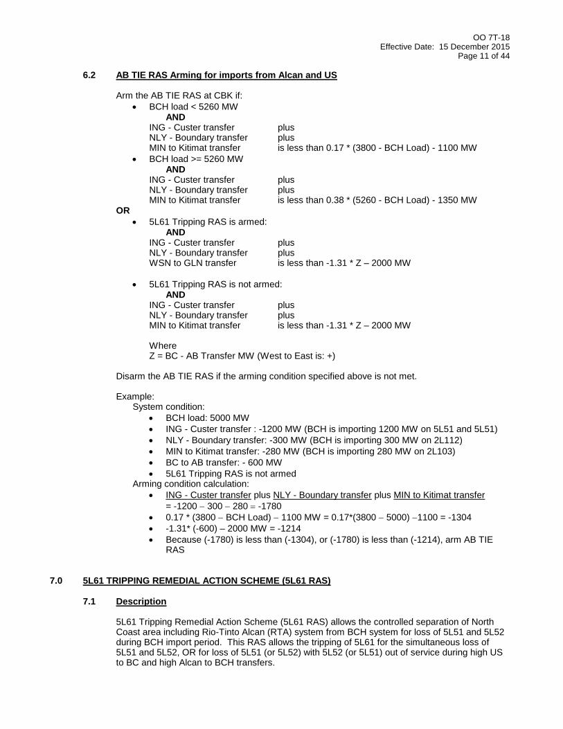
6.2 AB TIE RAS Arming for imports from Alcan and US Arm the AB TIE RAS at CBK if:
BCH load < 5260 MW AND
ING - Custer transfer plus NLY - Boundary transfer plus MIN to Kitimat transfer is less than 0.17 * (3800 - BCH Load) - 1100 MW
BCH load >= 5260 MW AND
ING - Custer transfer plus NLY - Boundary transfer plus MIN to Kitimat transfer is less than 0.38 * (5260 - BCH Load) - 1350 MW
OR
5L61 Tripping RAS is armed: AND
ING - Custer transfer plus NLY - Boundary transfer plus WSN to GLN transfer is less than -1.31 * Z – 2000 MW
5L61 Tripping RAS is not armed: AND
ING - Custer transfer plus NLY - Boundary transfer plus MIN to Kitimat transfer is less than -1.31 * Z – 2000 MW Where Z = BC - AB Transfer MW (West to East is: +)
Disarm the AB TIE RAS if the arming condition specified above is not met.
Example:
System condition:
BCH load: 5000 MW
ING - Custer transfer : -1200 MW (BCH is importing 1200 MW on 5L51 and 5L51)
NLY - Boundary transfer: -300 MW (BCH is importing 300 MW on 2L112)
MIN to Kitimat transfer: -280 MW (BCH is importing 280 MW on 2L103)
BC to AB transfer: - 600 MW
5L61 Tripping RAS is not armed Arming condition calculation:
ING - Custer transfer plus NLY - Boundary transfer plus MIN to Kitimat transfer
= -1200 300 280 -1780
0.17 * (3800 BCH Load) 1100 MW = 0.17*(3800 5000) 1100 = -1304
-1.31* (-600) – 2000 MW = -1214
Because (-1780) is less than (-1304), or (-1780) is less than (-1214), arm AB TIE RAS
7.0 5L61 TRIPPING REMEDIAL ACTION SCHEME (5L61 RAS) 7.1 Description
5L61 Tripping Remedial Action Scheme (5L61 RAS) allows the controlled separation of North Coast area including Rio-Tinto Alcan (RTA) system from BCH system for loss of 5L51 and 5L52 during BCH import period. This RAS allows the tripping of 5L61 for the simultaneous loss of 5L51 and 5L52, OR for loss of 5L51 (or 5L52) with 5L52 (or 5L51) out of service during high US to BC and high Alcan to BCH transfers.
OO 7T-18 Effective Date: 15 December 2015
Page 12 of 44
When armed during BCH moderate to heavy import conditions from US and high import from Alcan, the 5L61RAS will trip open 5L61 after loss of (5L51 and 5L52) OR loss of 5L51 (or 5L52) with 5L52 (or 5L51) out of service. The Energy Management System (EMS) Transient Stability Analysis (TSA) advanced application arms/disarms the 5L61 RAS. The BCHCC Transmission Coordinator is responsible for the arming and disarming of the 5L61 RAS at WSN. When TSA is unavailable, the BCHCC Transmission Coordinator can manually arm/disarm the 5L61RAS from the BCHCC EMS Generation Shedding Display.
7.2 5L61 RAS Arming for Imports from US and Alcan
Arm the 5L61 RAS at WSN if:
5L61 WSN <= 75 MW AND
(ING - Custer transfer) + (NLY - Boundary transfer) is less than: 0.125 × (3900 - BCH Load) – 600 MW
Disarm the 5L61 RAS if the arming conditions specified above are not met.
.

OO 7T-18 Effective Date: 15 December 2015
Page 13 of 44
8.0 SYSTEM OPERATING LIMITS (TRANSFER LIMITS) 8.1 General
In the following tables:
“BC to US” = net of the power flowing from BC to US, on ING-CUS 500 kV and NLY-BDY 230 kV ties
“US to BC” = net of the power flowing from US to BC, on CUS-ING 500 kV and BDY-NLY 230 kV ties
“Eastern tie” = NLY-BDY 230 kV tie
For import/export restrictions due to equipment outages in the BPA/PSE (Puget Sound Energy) system, refer to BPA Standing Order #320 that is updated by BPA. BPA may use limits other than those stated in BPA Standing Order #320 as a result of special operating studies. The BPA Dispatcher will advise the BCHCC Operator on special limits being used. The BPA and the BCHCC Operator must agree on the transfer limits between BC and US that will be used and posted on OASIS. The BCH SOLs in this order have been developed in accordance with the Peak RC System Operating Limit Methodology for the Operations Horizon Rev 7.
8.2 Corrective Measure when Transfer Limits Are Exceeded When the BC-US transfer limit or BC-Alberta transfer limit is exceeded, adjust the BC-Alberta transfer and/or BC-US transfer to stay within the limits recommended by TSA-PM and RTVSAT and VSLIM.
8.3 System Requirements for BC Exporting to US
8.3.1 5L51 or 5L52 Thermal Limit vs. Ambient Temperature at ING
The Amp rating of 5L51 or 5L52, in Attachment 1, is based on clearance requirements within BCH Engineering Standard 41K and the enforcement of right-of-way usage by BCH, and the 30-minute rating of ING CT (3300 A). The MW rating is equal to “1.732 x 0.99 x 515 kV x Amp rating /1000”. Attachment 2 shows the ING-CUS transfer limits for all system conditions. These ING-CUS transfer limits are to prevent the post-outage loading on 5L51 or 5L52 from exceeding its thermal limit upon any Peace, LM, or SI contingencies. Attachments 1 and 2 are implemented in TSA-PM. If the ING to CUS transfer limit has been exceeded, the BCHCC Operator must reduce the transfer below the limit by:
Adjusting NLY PST, or
Curtailing BC to US export schedule.
8.3.2 On-line Equivalent Burrard Synchronous Condensers (Attachment 3) Attachment 3 shows the ING to CUS transfer limits as a function of BCH load and the number of on-line equivalent Burrard synchronous condensers. Operating above the transfer limits will cause high voltages that can damage underground cables in the Lower Mainland upon the loss of 5L51 and 5L52 during light load condition. The BCHCC Operator must reduce the ING to CUS transfer to be within the transfer limit. TSA-PM will provide an alarm if the conditions in Attachment 3 are violated.

OO 7T-18 Effective Date: 15 December 2015
Page 14 of 44
8.3.3 Increasing the ING to CUS transfer above 2000 MW The following conditions must be met before increasing the ING to CUS transfer above 2000 MW. TSA-PM will automatically check these conditions and provide an alarm if any of the conditions is not met. 8.3.3.1 BC-Alberta transfer must be within the normal transfer limits specified in
Sections 10.1 and 10.2, OO 7T-17.
8.3.3.2 The RX RAS must be armed per Section 4.2. All auto-var schemes at ING, MDN, ACK and WSN must be in service. The auto-var scheme at SEL must be in service if SEL 5RX3 is available.
8.3.3.3 All 500 kV circuits must be in service except the following circumstances:
5L4 or 5L40, or 5L41, or 5L42, or 5L45, or 5L51, or 5L52, or 5L71, or 5L72, or 5L75, or 5L77, or 5L76, or 5L79, or 5L82, or 5L83, or 5L87, or 5L91, or 5L92, or 5L94, or 5L96, or 5L98, or 5L96 AND 5L98, or 5L94 AND 5L96 O.O.S (see Table A1 in this section for applicable transfer limits).
5L83 AND 5L4 or 5L83 AND 5L51, or 5L83 AND 5L52, or 5L83 AND 5L71, or 5L83 AND 5L72, or 5L83 AND 5L75, or 5L83 AND 5L77, or 5L83 AND 5L76, or 5L83 AND 5L79, or 5L83 AND 5L91, or 5L83 AND 5L92, or 5L83 AND 5L94, or 5L83 AND 5L96, or 5L83 AND 5L98, or 5L83 AND 5L96 AND 5L98, or 5L83 AND 5L94 AND 5L96 O.O.S (see Table A2 in this section for applicable transfer limits).
All combinations of the following conditions
One of (5L29 and 5L31) OOS
One of (5L30 and 5L32) OOS
5L61 OOS All limits in the tables are applicable under these conditions.
8.3.3.4 If all six ILM lines (5L40, 5L41, 5L42, 5L81, 5L82, and 5L83) are in service,
three of the CHP, CRK, RYC, AMC 5CX1 and AMC 5CX2 series capacitors (all segments) must be in service. If under one of the five conditions: 5L40 OR 5L41 OOS, 5L42 OOS, 5L81 OOS, 5L82 OOS, or 5L83 OOS, four of the CHP, CRK, RYC, AMC 5CX1 and AMC 5CX2 series capacitors must be in service.
8.3.3.5 Two of ING 2CX11, 2CX2, 2CX31 and 2CX32 must be available.

OO 7T-18 Effective Date: 15 December 2015
Page 15 of 44
8.3.3.6 The following reactors must be available:
ING 12RX4, 12RX5, 2RX1, 2RX2
KI2 One of (12RX1, 12RX3)
KLY 12RX1, 2RX2
MDN 12RX31, 12RX32, 2RX1, 2RX2
MSA 12RX1, 12RX2
TBY 2RX1 must be in service if 2L129 is energized. With the following exceptions:
If (2L129 + HVDC) ARN > 500 MW, then one of (TBY 2RX1, ING 12RX4, 12RX5, 2RX1, 2RX2) AND one of (MDN 12RX31, 12RX32, (12RX31 AND 12RX32), 2RX1, 2RX2) may be unavailable, OR If 300 MW < (2L129 + HVDC) ARN <= 500 MW, then one of (TBY 2RX1, ING 12RX4, 12RX5, 2RX1, 2RX2 AND MDN 12RX31, 12RX32, (12RX31 AND 12RX32), 2RX1, 2RX2) may be unavailable, OR If (2L129 + HVDC) ARN <= 300 MW, then one of (TBY 2RX1, MDN 12RX31, 12RX32, (12RX31 AND 12RX32), 2RX1, 2RX2) may be unavailable.
KLY 12RX1 may be unavailable if KLY S/C2 with AVR is in service
If 5L30 or 5L32 is O.O.S. then one of MSA 12RX1 and 12RX2 may be unavailable.
If 5L30 and 5L32 are in service AND If ING 12RX4, 12RX5, 2RX1, 2RX2 are available then one of the MSA 12RX1 and 12RX2 reactors may be unavailable.
Refer to Section 8.3.3.11.3 and Section 8.3.3.11.12, KLY 2RX2 may be unavailable.
8.3.3.7 At least 4 of (PIK 2RX2, SAT 2RX1, VIT S/C3, VIT S/C4, VIT S/C2) must be
in service. The AVR of VIT S/C must be on.
8.3.3.8 KLY S/C2 can be out of service if KLY 12RX1 is available.
8.3.3.9 Burrard S/C unit(s) or equivalent Burrard S/C unit(s) per Attachment 3 must be in service, and BGS 230 kV bus voltage must be less than 243 kV. If post-contingency voltage at ING 230 kV bus or MDN 230 kV bus exceeds 243 kV upon loss of 5L51 and 5L52, the BCHCC Operator should increase Mvar absorption from BGS to reduce the ING230 and MDN230 voltages below 243 kV within 15 minutes.
8.3.3.10 DMR SVC in automatic control mode with automatic control of DMR 500 kV reactor switching enabled must be in service.

OO 7T-18 Effective Date: 15 December 2015
Page 16 of 44
8.3.3.11 All 500 kV shunt reactors (VAS 5RX1 excluded) must be available with the following exceptions: 8.3.3.11.1 If 5L29 is O.O.S. OR
if 5L29 AND one of 5L30 and 5L32 are O.O.S then all of the following 500 kV reactors may be unavailable:
MSA 5RX1, and
TIR 5RX1/2/3, 5RX11/12/13 and 5RX21/22/23, and
DMR 5RX1, 5RX2, 5RX3 and 5RX4
8.3.3.11.2 If 5L31 is O.O.S. OR if 5L31 AND one of 5L30 and 5L32 are O.O.S. then all of the following 500 kV reactors may be unavailable:
MSA 5RX2, and
TIR 5RX4/5/6, 5RX14/15/16 and 5RX24/25/26, and
DMR 5RX5, 5RX6, 5RX7 and 5RX8
8.3.3.11.3 if 5L30 or 5L32 is O.O.S. AND if 5L29 and 5L31 and 5L98 are in service AND If ING 12RX4, 12RX5, 2RX1, 2RX2 are available Then
one of (KLY 12RX1, 2RX2, on-line KLY SC2 with AVR) may be unavailable, AND
one of the following 500 kV reactors may be unavailable:
MSA 5RX1 or 5RX2, or
TIR 5RX1/2/3 or 5RX11/12/13 or 5RX21/22/23 or 5RX4/5/6 , or
5RX14/15/16 or 5RX24/25/26, or
DMR 5RX1 or 5RX2 or 5RX3 or 5RX4 or 5RX5 or 5RX6 or 5RX7 or 5RX8.
8.3.3.11.4 If 5L61 is O.O.S. then WSN 5RX1 and GLN 5RX5 and TKW
5RX1 may be unavailable.
8.3.3.11.5 If 5L91 is O.O.S. then one of (SEL 5RX3, ACK (5RX4, 5RX7, 5RX8) may be unavailable.
8.3.3.11.6 If 5L92 or 5L94 is O.O.S. then
CBK 5RX4, or 5RX5 may be unavailable, AND
SEL 5RX3 may be unavailable.
8.3.3.11.7 If 5L96 is O.O.S. then SEL 5RX2 and SEL 5RX3 may be unavailable.
8.3.3.11.8 If 5L98 is O.O.S. AND If ING 12RX4, 12RX5, 2RX1, 2RX2 are available, Then one of (NIC (5RX3, 5RX4, 5RX9, 5RX10, 5RX11) and
ACK (5RX4, 5RX7, 5RX8)) may be unavailable.
8.3.3.11.9 If 5L96 AND 5L98 are O.O.S. then
SEL 5RX2 and SEL 5RX3 may be unavailable, AND
If ING 12RX4, 12RX5, 2RX1, 2RX2 are available, Then one of the NIC 5RX3 or 5RX4 or 5RX9 or 5RX10 or
5RX11 may be unavailable.

OO 7T-18 Effective Date: 15 December 2015
Page 17 of 44
8.3.3.11.10 If 5L94 AND 5L96 are O.O.S., then
SEL 5RX2 and SEL 5RX3 may be unavailable, AND
One of ACK (5RX4, 5RX7, 5RX8) may be unavailable, AND
CBK 5RX4 or CBK 5RX5 may be unavailable.
8.3.3.11.11 If no 500 kV circuit is O.O.S. AND if ING 12RX4, 12RX5, 2RX1, 2RX2 are available, Then one of the following 500 kV reactor(s) may be unavailable:
SEL 5RX2 or 5RX3 OR
NIC 5RX3 or 5RX4 or 5RX9 or 5RX10 or 5RX11 OR
CKY 5RX1 OR
MSA 5RX1 or 5RX2 OR
TIR 5RX1/2/3 or 5RX11/12/13 or 5RX21/22/23 or 5RX4/5/6 or 5RX14/15/16 or 5RX24/25/26 OR
DMR 5RX1 or 5RX2 or 5RX3 or 5RX4 or 5RX5 or 5RX6 or 5RX7 or 5RX8.
8.3.3.11.12 If no 500 kV circuit is O.O.S. AND If ING 12RX4, 12RX5, 2RX1, 2RX2 are available AND If KLY 12RX1 is available AND If KLY S/C2 with AVR is in service, then two of (KLY 2RX2, 5RX1, 5RX2, 5RX3, 5RX4, 5RX5, 5RX6) may be unavailable.
8.3.3.11.13 If 5L71 circuit is O.O.S. or 5L71&SYA 5CX2 are OOS, then
MCA 5RX4 may be unavailable, AND
One of the NIC 5RX3 or 5RX4 or 5RX9 or 5RX10 or 5RX11 may be unavailable, AND
SEL 5RX3 may be unavailable, AND
One of ACK (5RX4, 5RX7, 5RX8) may be unavailable.
8.3.3.11.14 If 5L72 circuit is O.O.S. or 5L72&SYA 5CX1 are OOS, then
MCA 5RX3 may be unavailable, AND
One of the NIC 5RX3 or 5RX4 or 5RX9 or 5RX10 or 5RX11 may be unavailable, AND
SEL 5RX3 may be unavailable, AND
One of ACK (5RX4, 5RX7, 5RX8) may be unavailable.
8.3.3.11.15 If 5L76 or 5L79 circuit is O.O.S., then
SEL 5RX3 may be unavailable. 8.3.3.11.16 If 5L75 or 5L77 circuit is O.O.S., then no exception, i.e.
All 500 kV shunt reactors (VAS 5CX1 excluded) must be available.
8.3.4 Operating Guidelines and Restrictions
Refer to the corresponding tables of Attachment 1 in OO 7T-34 for the operating guidelines and restrictions. System operating considerations affecting and affected by 2L112 operation are covered in Operating Orders 7T-17, 7T-33 and 7T-34.

OO 7T-18 Effective Date: 15 December 2015
Page 18 of 44
8.3.5 (5L83 AND 5L87 AND 5L71 OOS) or (5L83 AND 5L87 and 5L72 OOS)
Refer to Section 7.0 of OO 7T-34 and Table 2.18 in Attachment 1 of OO 7T-34 for operating guidelines and restrictions.
8.3.6 NTL Tie O.O.S. The system condition of “NTL Tie O.O.S.” includes:
1L274/887L O.O.S., or
1L275/786L O.O.S., or
1L274/887L AND 1L275/786L O.O.S., or
NTL T1 AND NTL T2 O.O.S., or
NTL 1VR1 O.O.S.
8.3.7 5L44 Contingency Refer to each table of Attachment 1 in OO 7T-34 for pre-outage restrictions in the Lower Mainland. These restrictions are required under certain ING to CUS or CUS to ING transfer levels to prevent overloading 60L15 upon loss of 5L44 and the subsequent tripping of 2L22 by its overload protection.
8.3.8 5L71 or 5L72 O.O.S with One MCA Unit On-Line Refer to Section 7.3.2 of OO 7T-33 for pre-outage restrictions. These restrictions are not implemented in TSA-PM. Also, refer to Table 1.2 in Attachment 1 of OO 7T-34 for other pre-outage restrictions associated with contingencies 5L91 or 5L96 or 5L98 or 5L96 AND 5L98, or 5L91 AND 5L96.
8.4 BC to US Transfer Limits (Export from BCH System) This section provides Path 3 North-South transfer limits for different system topologies. The path capability is a function of West side transfer (Ingledow to Custer) and East side transfer (Nelway to Boundary) where the Total Transfer Capability cannot exceed 3150 MW (Path Rating) or topology driven System Operating Limits noted in this section. The topologies defined in Tables A1 and A2 are for export cases, and are distinguished by system normal and elements out of service (Table A1), or 5L83 OOS with other elements also out of service (Table A2). The following notes are to be used where referenced in Table A1 and A2: Note 1: Arm ECS RAS per Sections 5.2. Note 2: If the actual transfer exceeds the following limit, the BCHCC Operator should adjust the
generation and/or schedule to reduce the transfer to within the limit In 30 minutes. Note 3: Limiting factor is to avoid the total armed gen-shedding exceeding 2500 MW for loss of
5L81. This limit can be raised with removal (bypass) of AMC 5CX1, which decreases flow on 5L81, reducing the generation shedding requirement. Operators can revise the transfer limit using real time studies provided the 2500 MW shedding limit is respected.
Note 4: Limiting factor is overload of 5L44. Transfer from VIT to ARN reduces the overload, and
will increase the transfer limit above 1950 MW. Note 5: Limiting factor is overload of 2L51. If higher ING-CUS transfer is required, 5L83 can be
switched off and the ING-CUS transfer can be increased to a maximum of 1700 MW. If Real Time Contingency Analysis (RTCA) does not indicate a thermal limit violation for next contingency, the transfer limit can be increased above 800 MW using real time study results.

OO 7T-18 Effective Date: 15 December 2015
Page 19 of 44
Note 6: Limiting factor is overload of 2L90 or 5L41. Note 7: Only the following system statuses in Table A2 (with 5L83 OOS) are implemented in
TSAPM in this revision:
5L83 AND 5L81 OOS
5L83 AND 5L87 AND (5L71 or 5L72) OOS
5L83 AND 5L44 OOS
These topologies are highlighted in Table A2.

OO 7T-18 Effective Date: 15 December 2015
Page 20 of 44
Table A1 - ING to CUS Transfer Limits for System Normal, N-1 or N-2 system status
The type of transfer limit is identified as follows: * Indicates a transient stability or voltage stability limit ** Indicates a thermal limit
No. System Status ING to CUS Transfer Limit (MW)
BC to US Transfer Limit (MW)
Remarks
1 System Normal, or 5L4 O.O.S., or 5L45 O.O.S., or 5L76 O.O.S., or 5L79 O.O.S., or 5L82 O.O.S., or 5L83 O.O.S., or NTL Tie O.O.S., or 2L113 or/and NTL T3&T4 O.O.S.
The least of: 1) 2850*, or 2) Attachment 2**, or 3) Attachment 3*, or 4) Attachment 4*, or 5) VSA ING to CUS limit*
The least of: 1) 3150*, or 2) ING to CUS limit + 400 3) VSA BC to US limit*
Note 1, Section 8.3.1 Section 8.3.2 Section 8.3.3 Section 8.3.4 Section 8.3.6
2. 5L91 O.O.S. The least of: 1) 2850*, or 2) Attachment 2**, or 3) Attachment 3*, or 4) Attachment 7*, or 5) VSA ING to CUS limit*
The least of: 1) 3150*, or 2) ING to CUS limit + 400 3) VSA BC to US limit*
Note 1, Section 8.3.1 Section 8.3.2 Section 8.3.3 Section 8.3.4
3. 5L92 O.O.S., or 5L94 O.O.S., or 5L96 O.O.S., or 5L98 O.O.S., or 5L96 & 5L98 O.O.S., or 5L94 AND 5L96 O.O.S.
The least of: 1) 2850*, or 2) Attachment 2**, or 3) Attachment 3*, or 4) VSA ING to CUS limit*
The least of: 1) 3150*, or 2) ING to CUS limit + 400 3) VSA BC to US limit*
Note 1, Section 8.3.1 Section 8.3.2 Section 8.3.3 Section 8.3.4
4. 5L51 O.O.S., or 5L52 O.O.S.
The least of: 1) Attachment 2**, or 2) Attachment 3*, or 3) Attachment 4*, or 4) VSA ING to CUS limit*
The lesser of: 1) ING to CUS limit + 400 2) VSA BC to US limit*
Note 1, Section 8.3.1 Section 8.3.2 Section 8.3.3
5. 5L40 O.O.S., or 5L41 O.O.S.
The least of: 1) 2400, or 2) Attachment 2**, or 3) Attachment 3*, or 4) Attachment 4*, or 5) VSA ING to CUS limit*
The lesser of: 1) ING to CUS limit + 400 2) VSA BC to US limit*
Note 1, Note 3, Section 8.3.1 Section 8.3.2 Section 8.3.4
6. 5L81 O.O.S. The least of: 1) 1950** – 0.28 × 2L129ARN, or 2) Attachment 2**, or 3) Attachment 3*, or 4) Attachment 4*, or 5) VSA ING to CUS limit*
The lesser of: 1) ING to CUS limit + 400 2) VSA BC to US limit*
Note 1, Note 4, Section 8.3.1 Section 8.3.2 Section 8.3.4
7. 5L44 O.O.S. The least of: 1) 800**, or 3) Attachment 2**, or 4) Attachment 3*, or 5) VSA ING to CUS limit*
The lesser of: 1) ING to CUS limit + 400 2) VSA BC to US limit*
Note 1, Note 5, Section 8.3.1 Section 8.3.2 Section 8.3.4
8. 5L42 O.O.S. The least of: 1) 2300**, or 2) Attachment 2**, or 3) Attachment 3*, or 4) Attachment 4*, or 5) VSA ING to CUS limit*
The lesser of: 1) ING to CUS limit + 400 2) VSA BC to US limit*
Note 1, Note 6, Section 8.3.1 Section 8.3.2
9. 5L87 O.O.S. The least of: 1) 2850*, or 2) Attachment 2**, or 3) Attachment 3*, or 4) Attachment 4*, or 5) VSA ING to CUS limit*
The least of: 1) 3150*, or 2) ING to CUS limit + 400 3) VSA BC to US limit*
Note 1, Section 8.3.1 Section 8.3.2
10. 2L112 O.O.S. The least of: 1) 2850*, or 2) Attachment 2**, or 3) Attachment 3*, or 4) Attachment 5*, or 5) VSA ING to CUS limit*
The lesser of: 1) ING to CUS limit 2) VSA BC to US limit*
Section 8.3.1 Section 8.3.2 Section 8.3.3 Section 8.3.4
11. 2L293 O.O.S. The least of: 1) 2850*, or 2) Attachment 2**, or 3) Attachment 3*, or 4) Attachment 6*, or 5) VSA ING to CUS limit*
The least of: 1) 3150*, or 2) ING to CUS limit + 400 3) VSA BC to US limit*
Note 1, Section 8.3.1 Section 8.3.2 Section 8.3.3 Section 8.3.4
12. 5L71 O.O.S., or 5L72 O.O.S., or 5L71 AND SYA 5CX2 O.O.S., or 5L72 AND SYA 5CX1 O.O.S.
The least of: 1) 2850*, or 2) Attachment 2**, or 3) Attachment 3*, or 4) Attachment 4*, or 5) VSA ING to CUS limit*
The least of: 1) 3150*, or 2) ING to CUS limit + 400 3) VSA BC to US limit*
Note 1, Section 8.3.1 Section 8.3.2 Section 8.3.3 Section 8.3.4
13. 5L75 O.O.S., or 5L77 O.O.S. The least of: 1) 2850*, or 2) Attachment 2**, or 3) Attachment 3*, or 4) Attachment 4*, or 5) VSA ING to CUS limit*
The least of: 1) 3150*, or 2) ING to CUS limit + 400 3) VSA BC to US limit*
Note 1, Section 8.3.1 Section 8.3.2 Section 8.3.3 Section 8.3.4
14. 5L71 AND 5L72 O.O.S. The least of: 1) 2000*, or 2) Attachment 2**, or 3) Attachment 3*, or 4) Attachment 4*, or 5) VSA ING to CUS limit*
The lesser of: 1) ING to CUS limit + 400 2) VSA BC to US limit*
Note 1, Section 8.3.1 Section 8.3.2 Section 8.3.4

OO 7T-18 Effective Date: 15 December 2015
Page 21 of 44
Table A2 - ING to CUS Transfer Limits for 5L83 AND Other Line/Equipment O.O.S
The type of transfer limit is identified as follows: * Indicates a transient stability or voltage stability limit ** Indicates a thermal limit
No. System Status ING to CUS Transfer Limit (MW)
BC to US Transfer Limit (MW)
Remarks
1 5L83 AND 5L4 O.O.S., or 5L83 AND 5L76 O.O.S., or 5L83 AND 5L79 O.O.S., or 5L83 AND NTL Tie O.O.S., or 5L83 AND 2L113 or/and NTL T3&T4 O.O.S
The least of: 1) 2850*, or 2) Attachment 2**, or 3) Attachment 3*, or 4) Attachment 4*, or 5) VSA ING to CUS limit*
The least of: 1) 3150*, or 2) ING to CUS limit + 400 3) VSA BC to US limit*
Note 1, Section 8.3.1 Section 8.3.2 Section 8.3.3 Section 8.3.4 Section 8.3.6
2 5L83 AND 5L91 O.O.S. The least of: 1) 2850*, or 2) Attachment 2**, or 3) Attachment 3*, or 4) Attachment 7*, or 5) VSA ING to CUS limit*
The least of: 1) 3150*, or 2) ING to CUS limit + 400 3) VSA BC to US limit*
Note 1, Section 8.3.1 Section 8.3.2 Section 8.3.3 Section 8.3.4
3 5L83 AND 5L92 O.O.S., or 5L83 AND 5L94 O.O.S., or 5L83 AND 5L96 O.O.S., or 5L83 AND 5L98 O.O.S., or 5L83 AND 5L96 & 5L98 O.O.S., or 5L83 AND 5L94 AND 5L96 O.O.S.
The least of: 1) 2850*, or 2) Attachment 2**, or 3) Attachment 3*, or 4) VSA ING to CUS limit*
The least of: 1) 3150*, or 2) ING to CUS limit + 400 3) VSA BC to US limit*
Note 1, Section 8.3.1 Section 8.3.2 Section 8.3.3 Section 8.3.4
4 5L83 AND 5L51 O.O.S., or 5L83 AND 5L52 O.O.S.
The least of: 1) Attachment 2**, or 2) Attachment 3*, or 3) Attachment 4*, or 4) VSA ING to CUS limit*
The lesser of: 1) ING to CUS limit + 400 2) VSA BC to US limit*
Note 1, Section 8.3.1 Section 8.3.2 Section 8.3.3
5 5L83 AND 5L40 O.O.S., or 5L83 AND 5L41 O.O.S., or 5L83 AND 5L44 O.O.S., or 5L83 AND 5L81 O.O.S., or 5L83 AND 5L82 O.O.S.
The least of: 1) 1700**, or 2) Attachment 2**, or 3) Attachment 3*, or 4) VSA ING to CUS limit*
The lesser of: 1) ING to CUS limit + 400 2) VSA BC to US limit*
Note 1, Section 8.3.1 Section 8.3.2 Section 8.3.4
6 5L83 AND 5L42 O.O.S. The least of: 1) 1300**, or 2) Attachment 2**, or 3) Attachment 3*, or 4) VSA ING to CUS limit*
The lesser of: 1) ING to CUS limit + 400 2) VSA BC to US limit*
Note 1, Section 8.3.1 Section 8.3.2
7 5L83 AND 5L87 AND (5L71 or 5L72) O.O.S.
The least of: 1) 2000*, or 2) Attachment 2**, or 3) Attachment 3*, or 4) Attachment 4*, or 5) VSA ING to CUS limit*
The lesser of: 1) ING to CUS limit + 400 2) VSA BC to US limit*
Note 1, Section 8.3.1 Section 8.3.2 Section 8.3.5
8 5L83 AND 2L112 O.O.S. The least of: 1) 2850*, or 2) Attachment 2**, or 3) Attachment 3*, or 4) Attachment 5*, or 5) VSA ING to CUS limit*
The lesser of: 1) ING to CUS limit 2) VSA BC to US limit*
Section 8.3.1 Section 8.3.2 Section 8.3.3 Section 8.3.4
9 5L83 AND 2L293 O.O.S. The least of: 1) 2850*, or 2) Attachment 2**, or 3) Attachment 3*, or 4) Attachment 6*, or 5) VSA ING to CUS limit*
The least of: 1) 3150*, or 2) ING to CUS limit + 400 3) VSA BC to US limit*
Note 1, Section 8.3.1 Section 8.3.2 Section 8.3.3 Section 8.3.4
10 5L83 AND 5L71 O.O.S., or 5L83 AND 5L72 O.O.S., or 5L83 AND 5L71 AND SYA 5CX2 O.O.S., or 5L83 AND 5L72 AND SYA 5CX1 O.O.S.
The least of: 1) 2400*, or 2) Attachment 2**, or 3) Attachment 3*, or 4) Attachment 4*, or 5) VSA ING to CUS limit*
The lesser of: 1) ING to CUS limit + 400 2) VSA BC to US limit*
Note 1, Section 8.3.1 Section 8.3.2 Section 8.3.3 Section 8.3.4
11 5L83 AND 5L75 O.O.S., or 5L83 AND 5L77 O.O.S.
The least of: 1) 2400*, or 2) Attachment 2**, or 3) Attachment 3*, or 4) Attachment 4*, or 5) VSA ING to CUS limit*
The lesser of: 1) ING to CUS limit + 400 2) VSA BC to US limit*
Note 1, Section 8.3.1 Section 8.3.2 Section 8.3.3 Section 8.3.4
12 5L83 AND 5L71 AND 5L72 O.O.S. The least of: 1) 2000*, or 2) Attachment 2**, or 3) Attachment 3*, or 4) Attachment 4*, or 5) VSA ING to CUS limit*
The lesser of: 1) ING to CUS limit + 400 2) VSA BC to US limit*
Note 1, Section 8.3.1 Section 8.3.2 Section 8.3.4

OO 7T-18 Effective Date: 15 December 2015
Page 22 of 44
8.5 System Requirements for BC Importing from US 8.5.1 5L51 or 5L52 Thermal Limit versus Ambient Temperature at Ingledow
The Amp rating of 5L51 or 5L52, in Attachment 1, is based on clearance requirements within BCH Engineering Standard 41K, the enforcement of right-of-way usage by BCH, and the 30-minute rating of ING CT (3300 A). The MW rating is equal to “1.732 x 0.99 x 515 kV x Amp rating /1000”. Attachment 2 shows the CUS to ING transfer limits for all system conditions. The transfer limit is to prevent the post-outage loading on 5L51 or 5L52 from exceeding its thermal limit for any Peace, LM, or SI contingencies. Attachments 1 and 2 are implemented in TSA-PM. If the CUS to ING transfer limit has been exceeded, TSA-PM will give an alarm to indicate the dominant factor which causes the violation. The BCHCC Operator should reduce the transfer below the limit.
DO NOT schedule 5L51 or 5L52 maintenance outage during high imports from US. Without 5L51 or 5L52 in service, the CUS to ING transfer limit may be very low. After generation shedding due to the worst Peace, LM or SI contingency, about 70% to 90% of the shed generation would flow on the ING-CUS circuit. The CUS-ING transfer limit takes into consideration that this additional MW flow will not overload the single ING-CUS circuit for the worst contingency.
8.5.2 (5L83 AND 5L87 AND 5L71 OOS) or (5L83 AND 5L87 AND 5L72 OOS)
Refer to Section 7.0 of OO 7T-34 and Table 2.18 in Attachment 1 of OO 7T-34 for the operating guidelines and restrictions.
8.5.3 NTL Tie O.O.S. The system condition of “NTL Tie O.O.S.” includes:
1L274/887L O.O.S., or
1L275/786L O.O.S., or
1L274/887L AND 1L275/786L O.O.S., or
NTL T1 AND NTL T2 O.O.S., or
NTL 1VR1 O.O.S.
8.5.4 Operating Guidelines and Restrictions Refer to the corresponding tables of Attachment 1 in OO 7T-34 for the operating guidelines and restrictions. System operating considerations affecting and affected by 2L112 operation are covered in Operating Orders 7T-17, 7T-33 and 7T-34.
8.5.5 5L71 or 5L72 O.O.S with One MCA Unit On-Line Operations with one of 5L71 or 5L72 OOS and only one MCA generating unit are no longer supported, as studies with the Seymour Arm Capacitor station (SYA) in service has not been undertaken. There are no plans to operate with one line–one unit configuration for future. In the event of a forced outage leading to a one line one unit condition, a second unit must be resynchronized immediately. If it is not possible to operate with 2 units in
OO 7T-18 Effective Date: 15 December 2015
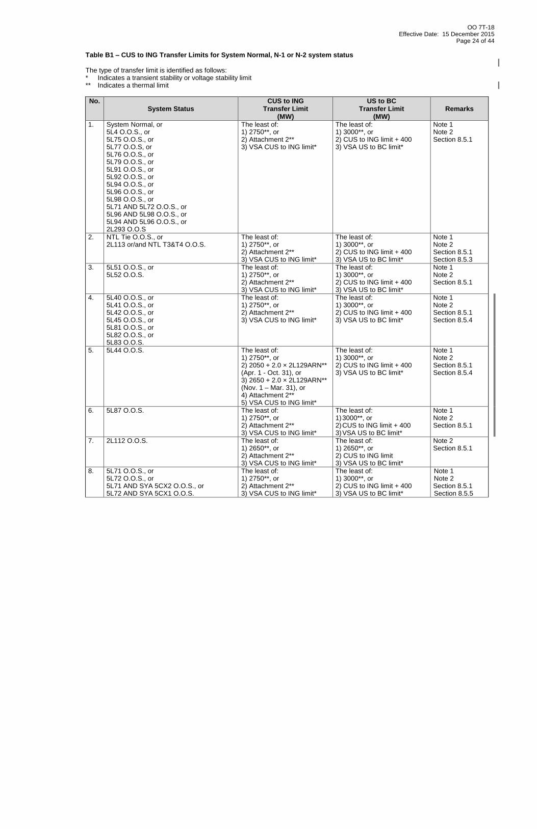
Page 23 of 44
service, the plant/unit must be islanded (by opening the remaining 500 kV line). This requirement prevents self-excitation risks to the one unit that remains on line.
8.6 US-BC Transfer Limits (Import into BCH System)
This section provides Path 3 South-North transfer limits for different system topologies. The path capability is a function of West side transfer (Custer to Ingledow) and East side transfer (Boundary to Nelway) where the Total Transfer Capability cannot exceed 3000 MW (Path Rating) or topology driven System Operating Limits noted in this section. As a result of the agreement with BPA, BC Hydro’s TSA-PM, operating tools and procedures will observe a transfer capability limit of 2000 MW (south to north). This operating practice of capping the transfer limit will remain in effect until such time as BPA studies are completed, verifying conditions and requirements for operating above 2000 MW up to the Path Rating. When BPA has a path facility out of service, the limit provided by BPA may be more restrictive. The lesser of the BC Hydro limit and the BPA limit, not exceeding the cap, will be used. The topologies defined in Tables B1 and B2 are for import transfer cases, and are distinguished by system normal and elements out of service (Table B1), or 5L83 OOS with other elements also out of service (Table B2). The following notes are to be used where referenced in Table B1 and B2: Note 1: Arm ECS RAS per Section 5.2. Note 2: Arm AB TIE RAS per Section 6.2. Note 3: Only the following system statuses with 5L83 OOS are implemented in TSAPM in
this revision:
5L83 AND 5L81 OOS
5L83 AND 5L87 AND (5L71 or 5L72) OOS
5L83 AND 5L44 OOS
OO 7T-18 Effective Date: 15 December 2015
Page 24 of 44
Table B1 – CUS to ING Transfer Limits for System Normal, N-1 or N-2 system status
The type of transfer limit is identified as follows: * Indicates a transient stability or voltage stability limit ** Indicates a thermal limit
No. System Status
CUS to ING Transfer Limit
(MW)
US to BC Transfer Limit
(MW) Remarks
1. System Normal, or 5L4 O.O.S., or 5L75 O.O.S., or 5L77 O.O.S, or 5L76 O.O.S., or 5L79 O.O.S., or 5L91 O.O.S., or 5L92 O.O.S., or 5L94 O.O.S., or 5L96 O.O.S., or 5L98 O.O.S., or 5L71 AND 5L72 O.O.S., or 5L96 AND 5L98 O.O.S., or 5L94 AND 5L96 O.O.S., or 2L293 O.O.S
The least of: 1) 2750**, or 2) Attachment 2** 3) VSA CUS to ING limit*
The least of: 1) 3000**, or 2) CUS to ING limit + 400 3) VSA US to BC limit*
Note 1 Note 2 Section 8.5.1
2. NTL Tie O.O.S., or 2L113 or/and NTL T3&T4 O.O.S.
The least of: 1) 2750**, or 2) Attachment 2** 3) VSA CUS to ING limit*
The least of: 1) 3000**, or 2) CUS to ING limit + 400 3) VSA US to BC limit*
Note 1 Note 2 Section 8.5.1 Section 8.5.3
3. 5L51 O.O.S., or 5L52 O.O.S.
The least of: 1) 2750**, or 2) Attachment 2** 3) VSA CUS to ING limit*
The least of: 1) 3000**, or 2) CUS to ING limit + 400 3) VSA US to BC limit*
Note 1 Note 2 Section 8.5.1
4. 5L40 O.O.S., or 5L41 O.O.S., or 5L42 O.O.S., or 5L45 O.O.S., or 5L81 O.O.S., or 5L82 O.O.S., or 5L83 O.O.S.
The least of: 1) 2750**, or 2) Attachment 2** 3) VSA CUS to ING limit*
The least of: 1) 3000**, or 2) CUS to ING limit + 400 3) VSA US to BC limit*
Note 1 Note 2 Section 8.5.1 Section 8.5.4
5. 5L44 O.O.S.
The least of: 1) 2750**, or 2) 2050 + 2.0 × 2L129ARN** (Apr. 1 - Oct. 31), or 3) 2650 + 2.0 × 2L129ARN** (Nov. 1 – Mar. 31), or 4) Attachment 2** 5) VSA CUS to ING limit*
The least of: 1) 3000**, or 2) CUS to ING limit + 400 3) VSA US to BC limit*
Note 1 Note 2 Section 8.5.1 Section 8.5.4
6. 5L87 O.O.S. The least of: 1) 2750**, or 2) Attachment 2** 3) VSA CUS to ING limit*
The least of: 1) 3000**, or 2) CUS to ING limit + 400 3) VSA US to BC limit*
Note 1 Note 2 Section 8.5.1
7. 2L112 O.O.S. The least of: 1) 2650**, or 2) Attachment 2** 3) VSA CUS to ING limit*
The least of: 1) 2650**, or 2) CUS to ING limit 3) VSA US to BC limit*
Note 2 Section 8.5.1
8. 5L71 O.O.S., or 5L72 O.O.S., or 5L71 AND SYA 5CX2 O.O.S., or 5L72 AND SYA 5CX1 O.O.S.
The least of: 1) 2750**, or 2) Attachment 2** 3) VSA CUS to ING limit*
The least of: 1) 3000**, or 2) CUS to ING limit + 400 3) VSA US to BC limit*
Note 1 Note 2 Section 8.5.1 Section 8.5.5
OO 7T-18 Effective Date: 15 December 2015
Page 25 of 44
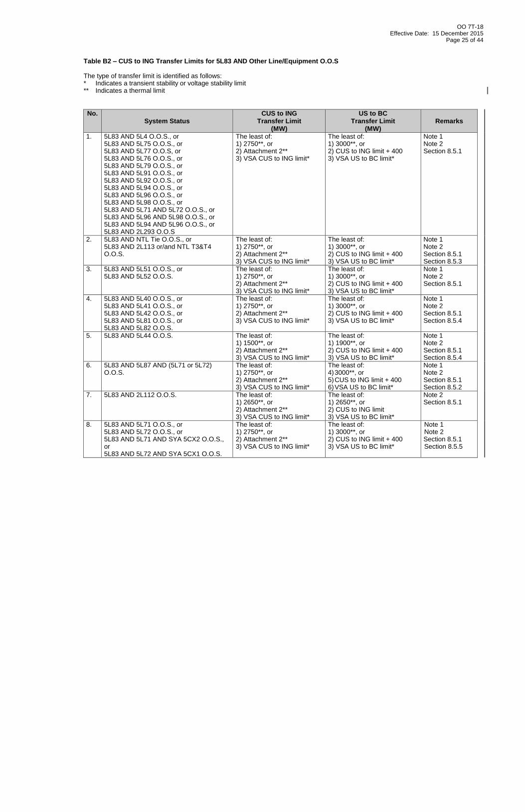
Table B2 – CUS to ING Transfer Limits for 5L83 AND Other Line/Equipment O.O.S
The type of transfer limit is identified as follows: * Indicates a transient stability or voltage stability limit ** Indicates a thermal limit
No. System Status
CUS to ING Transfer Limit
(MW)
US to BC Transfer Limit
(MW) Remarks
1. 5L83 AND 5L4 O.O.S., or 5L83 AND 5L75 O.O.S., or 5L83 AND 5L77 O.O.S, or 5L83 AND 5L76 O.O.S., or 5L83 AND 5L79 O.O.S., or 5L83 AND 5L91 O.O.S., or 5L83 AND 5L92 O.O.S., or 5L83 AND 5L94 O.O.S., or 5L83 AND 5L96 O.O.S., or 5L83 AND 5L98 O.O.S., or 5L83 AND 5L71 AND 5L72 O.O.S., or 5L83 AND 5L96 AND 5L98 O.O.S., or 5L83 AND 5L94 AND 5L96 O.O.S., or 5L83 AND 2L293 O.O.S
The least of: 1) 2750**, or 2) Attachment 2** 3) VSA CUS to ING limit*
The least of: 1) 3000**, or 2) CUS to ING limit + 400 3) VSA US to BC limit*
Note 1 Note 2 Section 8.5.1
2. 5L83 AND NTL Tie O.O.S., or 5L83 AND 2L113 or/and NTL T3&T4 O.O.S.
The least of: 1) 2750**, or 2) Attachment 2** 3) VSA CUS to ING limit*
The least of: 1) 3000**, or 2) CUS to ING limit + 400 3) VSA US to BC limit*
Note 1 Note 2 Section 8.5.1 Section 8.5.3
3. 5L83 AND 5L51 O.O.S., or 5L83 AND 5L52 O.O.S.
The least of: 1) 2750**, or 2) Attachment 2** 3) VSA CUS to ING limit*
The least of: 1) 3000**, or 2) CUS to ING limit + 400 3) VSA US to BC limit*
Note 1 Note 2 Section 8.5.1
4. 5L83 AND 5L40 O.O.S., or 5L83 AND 5L41 O.O.S., or 5L83 AND 5L42 O.O.S., or 5L83 AND 5L81 O.O.S., or 5L83 AND 5L82 O.O.S.
The least of: 1) 2750**, or 2) Attachment 2** 3) VSA CUS to ING limit*
The least of: 1) 3000**, or 2) CUS to ING limit + 400 3) VSA US to BC limit*
Note 1 Note 2 Section 8.5.1 Section 8.5.4
5. 5L83 AND 5L44 O.O.S.
The least of: 1) 1500**, or 2) Attachment 2** 3) VSA CUS to ING limit*
The least of: 1) 1900**, or 2) CUS to ING limit + 400 3) VSA US to BC limit*
Note 1 Note 2 Section 8.5.1 Section 8.5.4
6. 5L83 AND 5L87 AND (5L71 or 5L72) O.O.S.
The least of: 1) 2750**, or 2) Attachment 2** 3) VSA CUS to ING limit*
The least of: 4) 3000**, or 5) CUS to ING limit + 400 6) VSA US to BC limit*
Note 1 Note 2 Section 8.5.1 Section 8.5.2
7. 5L83 AND 2L112 O.O.S. The least of: 1) 2650**, or 2) Attachment 2** 3) VSA CUS to ING limit*
The least of: 1) 2650**, or 2) CUS to ING limit 3) VSA US to BC limit*
Note 2 Section 8.5.1
8. 5L83 AND 5L71 O.O.S., or 5L83 AND 5L72 O.O.S., or 5L83 AND 5L71 AND SYA 5CX2 O.O.S., or 5L83 AND 5L72 AND SYA 5CX1 O.O.S.
The least of: 1) 2750**, or 2) Attachment 2** 3) VSA CUS to ING limit*
The least of: 1) 3000**, or 2) CUS to ING limit + 400 3) VSA US to BC limit*
Note 1 Note 2 Section 8.5.1 Section 8.5.5
OO 7T-18 Effective Date: 15 December 2015
Page 26 of 44
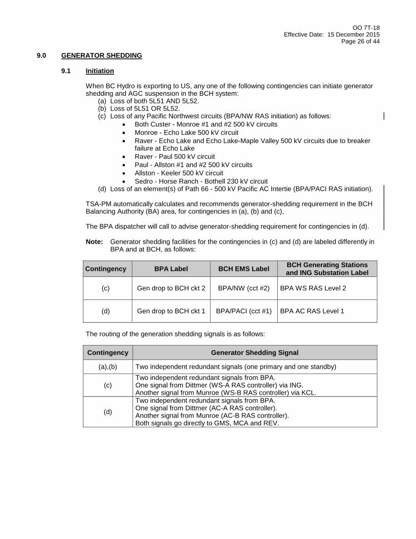
9.0 GENERATOR SHEDDING 9.1 Initiation
When BC Hydro is exporting to US, any one of the following contingencies can initiate generator shedding and AGC suspension in the BCH system:
(a) Loss of both 5L51 AND 5L52. (b) Loss of 5L51 OR 5L52. (c) Loss of any Pacific Northwest circuits (BPA/NW RAS initiation) as follows:
Both Custer - Monroe #1 and #2 500 kV circuits
Monroe - Echo Lake 500 kV circuit
Raver - Echo Lake and Echo Lake-Maple Valley 500 kV circuits due to breaker failure at Echo Lake
Raver - Paul 500 kV circuit
Paul - Allston #1 and #2 500 kV circuits
Allston - Keeler 500 kV circuit
Sedro - Horse Ranch - Bothell 230 kV circuit (d) Loss of an element(s) of Path 66 - 500 kV Pacific AC Intertie (BPA/PACI RAS initiation).
TSA-PM automatically calculates and recommends generator-shedding requirement in the BCH Balancing Authority (BA) area, for contingencies in (a), (b) and (c), The BPA dispatcher will call to advise generator-shedding requirement for contingencies in (d). Note: Generator shedding facilities for the contingencies in (c) and (d) are labeled differently in
BPA and at BCH, as follows:
Contingency BPA Label BCH EMS Label BCH Generating Stations and ING Substation Label
(c)
Gen drop to BCH ckt 2
BPA/NW (cct #2)
BPA WS RAS Level 2
(d)
Gen drop to BCH ckt 1
BPA/PACI (cct #1)
BPA AC RAS Level 1
The routing of the generation shedding signals is as follows:
Contingency Generator Shedding Signal
(a),(b) Two independent redundant signals (one primary and one standby)
(c) Two independent redundant signals from BPA. One signal from Dittmer (WS-A RAS controller) via ING. Another signal from Munroe (WS-B RAS controller) via KCL.
(d)
Two independent redundant signals from BPA. One signal from Dittmer (AC-A RAS controller). Another signal from Munroe (AC-B RAS controller). Both signals go directly to GMS, MCA and REV.

OO 7T-18 Effective Date: 15 December 2015
Page 27 of 44
9.2 Allocation The generation plants available for shedding for each of the contingencies listed in Section 9.1 are specified in Sections 9.3 to 9.7 respectively. Allocation of generator shedding between the available generation plants is left to the BCH Transmission Coordinator’s discretion. Some considerations regarding generator shedding are:
Shedding base loaded units rather than AGC controlled units will require fewer changes to shedding.
At high export levels, splitting shedding between the available generation plants should reduce voltage problems and improve restoration time.
If manual generation shedding is required at MCA, select the MCA unit(s) above 435 MW for shedding first.
If generation shedding is required at PCN for any contingencies in OO 7T-18, the general requirements in Section 5.5.2 in OO 7T-13 shall be followed.
After generation shedding for the loss of 5L51 and 5L52 or the BPA outages, a minimum of the following generator units should remain on-line to control post-disturbance voltages:
At MCA:
2 MCA units for all system conditions with the exception of both 5L71 and 5L72 O.O.S. or
0 MCA unit for both 5L71 and 5L72 O.O.S. AND
2 REV units, AND
2 SEV units, AND
1 KCL unit with high side 2CBs in service, AND
1 equivalent SEV units if SEL 5RX3 is unavailable, AND
1 WAN unit if WAN generating shedding is required, AND
at GMS and PCN:
4 GMS and 3 PCN units, OR
5 GMS and 2 PCN units, OR
6 GMS and 1 PCN units only if 5L4 is in service, OR
7 GMS and 0 PCN units.
(Note: 1 KCL unit = 2/3 equivalent SEV unit 1 ALH unit = 1/3 equivalent SEV unit 1 WAX unit = 1 equivalent SEV unit)
If fewer units are at each plant than as specified above for the pre-disturbance condition, consult System Performance Assessment to do special studies. Breaker failure protections on Waneta G1, G2, G3 and G4 have been commissioned and put into service (refer to Section 4.3 of OO 7T-34 for details). Hence the previous requirement to shed one extra WAN unit, to cover potential WAN circuit breaker failure problem, is no longer needed and has been removed. WAN G4 shall not participate in any generation shedding requirement. This is a generic rule in TSA-PM implementation.
OO 7T-18 Effective Date: 15 December 2015
Page 28 of 44
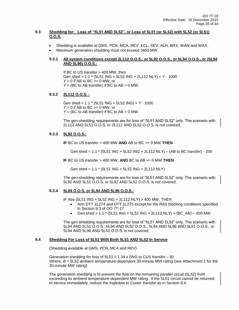
9.3 Shedding for: Loss of “5L51 AND 5L52”, or Loss of 5L51 (or 5L52) with 5L52 (or 5L51) O.O.S.
Shedding is available at GMS, PCN, MCA, REV, KCL, SEV, ALH, BRX, WAN and WAX.
Maximum generation shedding must not exceed 3450 MW. 9.3.1 All system conditions except 2L112 O.O.S., or 5L92 O.O.S., or 5L94 O.O.S., or (5L94
AND 5L96) O.O.S.: If BC to US transfer > 400 MW, then Gen shed = 1.1 * (5L51 ING + 5L52 ING + 2L112 NLY) + Y - 1000 Y = 0 if AB to BC >= 0 MW, or Y = (BC to AB transfer) if BC to AB > 0 MW.
9.3.2 2L112 O.O.S. : Gen shed = 1.1 * (5L51 ING + 5L52 ING) + Y - 1000 Y = 0 if AB to BC >= 0 MW, or Y = (BC to AB transfer) if BC to AB > 0 MW. The gen-shedding requirements are for loss of “5L51 AND 5L52” only. The scenario with 2L112 AND 5L51 O.O.S. or 2L112 AND 5L52 O.O.S. is not covered.
9.3.3 5L92 O.O.S.: IF BC to US transfer > 400 MW AND AB to BC >= 0 MW THEN
Gen shed = 1.1 * (5L51 ING + 5L52 ING + 2L112 NLY) – (AB to BC transfer) - 200
IF BC to US transfer > 400 MW, AND BC to AB >= 0 MW THEN Gen shed = 1.1 * (5L51 ING + 5L52 ING + 2L112 NLY)
The gen-shedding requirements are for loss of “5L51 AND 5L52” only. The scenario with 5L92 AND 5L51 O.O.S. or 5L92 AND 5L52 O.O.S. is not covered.
9.3.4 5L94 O.O.S. or 5L94 AND 5L96 O.O.S.: IF Abs (5L51 ING + 5L52 ING + 2L112 NLY) > 400 MW, THEN
Arm DTT 1L274 and DTT 1L275 except for the RAS blocking conditions specified in Section 9.3 of OO 7T-17
Gen shed = 1.1 * (5L51 ING + 5L52 ING + 2L112 NLY) + (BC_AB) – 400 MW
The gen-shedding requirements are for loss of “5L51 AND 5L52” only. The scenario with 5L94 AND 5L51 O.O.S., 5L94 AND 5L52 O.O.S., 5L94 AND 5L96 AND 5L51 O.O.S., or 5L94 AND 5L96 AND 5L52 O.O.S. is not covered.
9.4 Shedding For Loss of 5L51 With Both 5L51 AND 5L52 In Service
(Shedding available at GMS, PCN, MCA and REV) Generation shedding for loss of 5L51 = 1.34 x (ING to CUS transfer – B) Where, B = 5L52 ambient temperature-dependent 30-minute MW rating (see Attachment 1 for the 30-minute MW rating).
The generation shedding is to prevent the flow on the remaining parallel circuit (5L52) from exceeding its ambient temperature-dependent MW rating. If the 5L51 circuit cannot be returned to service immediately, reduce the Ingledow to Custer transfer as in Section 8.4.
OO 7T-18 Effective Date: 15 December 2015
Page 29 of 44
9.5 Shedding For Loss of 5L52 With Both 5L51 AND 5L52 In Service (Shedding available at GMS, PCN, MCA and REV) Generation shedding for loss of 5L52 = 1.27 x (ING to CUS transfer - B) Where, B = 5L51 ambient temperature-dependent 30-minute MW rating (see Attachment 1 for the 30-minute MW rating).
The generation shedding is to prevent the flow on the remaining parallel circuit (5L51) from exceeding its ambient temperature-dependent MW rating. If the 5L52 circuit cannot be returned to service immediately, reduce the Ingledow to Custer transfer as in Section 8.4.
9.6 Shedding for Loss of Pacific Northwest Circuits (BPA/NW RAS) BCH calls this RAS the “BPA/NW RAS”. BPA calls it the “Gen Drop to BCH Circuit 2” RAS. Shedding for this RAS is available at GMS, PCN, MCA, REV, KCL and SEV. Normally, when the ING to CUS transfer is higher than 800 MW, BC Hydro will shed generation and suspend AGC for the following contingencies in the Northwest:
Loss of Custer - Monroe #1 and #2 500 kV circuits
Loss of Monroe - Echo Lake 500 kV circuit
Loss of Raver - Echo Lake 500 kV and Echo Lake-Maple Valley 500 kV circuits
Loss of Raver - Paul 500 kV circuit
Loss of Paul - Allston #1 and #2 500 kV circuits
Loss of Allston - Keeler 500 kV circuit
Loss of Sedro - Horse Ranch - Bothell 230 kV circuit
The arming level for transfer greater than 800 MW is called the “BPA Normal” or “800 MW” Arming Level in BPA’s terminology. The TSA-PM determines the amount of BC Hydro shedding using the following formula:
Ingledow to Custer Actual Transfer (MW)
Shedding Requirement at “800 MW Arming Level” of BPA/NW RAS for Northwest Contingencies in Section 9.6
-2750 to +800 None
+801 to +2850 1.5 x (ING to CUS transfer – 800). Maximum of 1850 MW shed
At times, BPA will require BC Hydro generation shedding and AGC suspension when the ING to CUS transfer exceeds only 100 MW for the same contingencies. This is called the “BPA Outage” or “100 MW” Arming Level. The TSA-PM determines the amount of BC Hydro generation using the following formula:
Ingledow to Custer Actual Transfer (MW)
Shedding Requirement at “100 MW Arming Level” of BPA/NW RAS for Northwest Contingencies in Section 9.6
-2750 to +100 None
+101 to +2850 0.95 x (ING to CUS transfer – 100). Maximum of 1850 MW shed
Notes
1. Do not undershed. 2. The requirement is to shed up to 1850 MW per the formula. The actual amount of
generation armed for shedding, whether determined by TSA-PM or manually, may be slightly higher than the requirement depending on the loading of generators available for shedding.
The BCH Transmission Coordinator can select the “800 MW” Arming Level or “100 MW” Arming Level by toggling a switch on the EMS Generation Shedding Overview display. The BPA RAS Dispatcher will call the BCH Transmission Coordinator when the arming level is changed and the time of the change, as follows:
OO 7T-18 Effective Date: 15 December 2015
Page 30 of 44
1) BPA will say “Circuit #2 Gen Drop Arming Level at 100 MW, effective at …..” when the
formula 0.95 x (Ingledow>Custer – 100) is used. 2) BPA will say “Circuit #2 Gen Drop Arming Level at 800 MW, effective at …..” when the
formula 1.5 x (Ingledow>Custer – 800) is used.
The BPA RAS Dispatcher will call the BCH Transmission Coordinator when the status of the “Circuit #2 Gen Drop RAS” is changed, i.e. from armed to disarmed, or from disarmed to armed. When AB is exporting more than 700 MW, then the preferred gen-shedding sequence is: GMS/PCN, MCA, REV and the last at SEV and KCL. (Note: The preferred gen-shedding sequence is not implemented in TSAPM in this revision).
9.7 Shedding for Loss of an Element(s) of the U.S. 500 kV Pacific AC Intertie (BPA/PACI RAS)
BCH calls this RAS the “PACI RAS”. BPA calls it the “Gen Drop to BCH Circuit 1” RAS. Shedding for this RAS is available at GMS, PCN, MCA and REV. Provided that BCH is exporting to the U.S. Southwest using the PACI and/or the Pacific HVDC Intertie, the BPA Dittmer Dispatcher can request the BCHCC Operator to participate in generator shedding for PACI contingencies. The Dittmer Dispatcher will specify a MW figure for generation to be put on shed and the BCHCC Operator selects the appropriate plant and generators. The total amount of shedding requested cannot exceed the total of BCH/FortisBC schedules to the U.S. Southwest on the PACI and/or the HVDC. When AB is exporting more than 700 MW, then the preferred gen-shedding sequence is: GMS/PCN, MCA, and the last at REV (Note: The preferred gen-shedding sequence is not implemented in TSAPM in this revision).
10.0 AUTOMATIC GENERATION CONTROL (AGC) SUSPENSION See OO 2T-43 for details of AGC suspension.

OO 7T-18 Effective Date: 15 December 2015
Page 31 of 44
11.0 TSA-PM IMPLEMENTATION With respect to OO 7T-18, the EMS Transient Stability Analysis – Pattern Matching (TSA-PM) advanced application arms/disarms generators to be shed for:
Loss of 5L51 AND 5L52
Loss of 5L51
Loss of 5L52
BPA / NW RAS operation.
TSA-PM normally arms/disarms the ECS RAS, the RX RAS, and the AB Tie RAS. TSA-PM arms DTT of 5L83 for 5L51 AND 5L52 double contingency for system conditions identified in Section 4.2. All transfer limits in OO 7T-18 have been implemented in TSA-PM and will alarm in AOR GS if the limits are violated.

OO 7T-18 Effective Date: 15 December 2015
Page 32 of 44
The following alarms have been implemented in TSA-PM:
ALSTOM EMS AOR
ALARM DESCRIPTION ALARM PRIORITY
PI Tag REMARKS
TRANSMSN TSA-PM 7T-18 - ING_CUS 2850 - REQD 500KV CCTS NOT I/S 2 To be implemented Section 8.3.3 Conditions required for increasing the ING to CUS transfer above 2000 MW
TRANSMSN TSA-PM 7T-18 - NO 500 KV CONNECTION TO VI 2 To be implemented TRANSMSN TSA-PM 7T-18 - ING_CUS 2850 - REQUIRED SERIES CAPS OOS 2 To be implemented TRANSMSN TSA-PM 7T-18 - ING_CUS 2850: REQD ING CAPS NOT AVAIL 2 To be implemented TRANSMSN TSA-PM 7T-18 - ING_CUS 2850: ING REQD LV RXS NOT AVAIL 2 To be implemented TRANSMSN TSA-PM 7T-18 - ING_CUS 2850: REQD KI2 RX NOT AVAIL 2 To be implemented TRANSMSN TSA-PM 7T-18 - ING_CUS 2850: KLY 2RX2 NOT AVAILABLE 2 To be implemented TRANSMSN TSA-PM 7T-18 - ING_CUS 2850: MSA 12RX1 & 2 NOT AVAIL 2 To be implemented TRANSMSN TSA-PM 7T-18 - ING_CUS 2850: REQD VIT SCS/SAT PIK RXS NOT
AVAIL 2 To be implemented
TRANSMSN TSA-PM 7T-18 - ING_CUS 2850: KLY_SC2 OR 12RX1 NOT AVAL 2 To be implemented TRANSMSN TSA-PM 7T-18 - ING_CUS 2850:DMR SVC REQRMNTS NOT MET 2 To be implemented TRANSMSN TSA-PM 7T-18 - ING_CUS 2850: REQD 500KV RXS NOT AVAIL 2 To be implemented TRANSMSN TSA-PM 7T-18 - ING_CUS 2850: REQD ACK RXS NOT AVAIL 2 To be implemented TRANSMSN TSA-PM 7T-18 - ING_CUS 2850: REQD CBK RXS NOT AVAIL 2 To be implemented TRANSMSN TSA-PM 7T-18 - ING_CUS 2850: MDN REQD LV RXS NOT AVAIL 2 To be implemented TRANSMSN TSA-PM 7T-18 - TBY 2RX1 MUST IN SERVICE WHEN 2L129
ENERGIZED 2 To be implemented
TRANSMSN TSA-PM 7T-18 - ING_CUS 2850:TBY/ING REQD LV RXS NOT AVAIL 2 To be implemented TRANSMSN TSA-PM 7T-18 - ING_CUS 2850: TBY/ING/MDN REQD LV RXS NOT
AVAIL 2 To be implemented
TRANSMSN TSA-PM 7T-18 - ING_CUS 2850: TBY/MDN REQD LV RXS NOT AVAIL
2 To be implemented
TRANSMSN TSA-PM 7T-18 - ING_CUS 2850: REQD ACK/SEL RXS NOT AVAIL 2 To be implemented TRANSMSN TSA-PM 7T-18 - ING AUTO-VAR MUST BE IN SERVICE 2 To be implemented TRANSMSN TSA-PM 7T-18 - MDN AUTO-VAR MUST BE IN SERVICE 2 To be implemented TRANSMSN TSA-PM 7T-18 - ACK AUTO-VAR MUST BE IN SERVICE 2 To be implemented TRANSMSN TSA-PM 7T-18 - WSN AUTO-VAR MUST BE IN SERVICE 2 To be implemented TRANSMSN TSA-PM 7T-18 - SEL AUTO-VAR MUST BE IN SERVICE 2 To be implemented TRANSMSN TSA-PM 7T-18 - BGS 230KV BUS VOLTAGE REQRMNT NOT MET 2 To be implemented TRANSMSN TSA-PM 7T-18 - ING_CUS 2850: KLY RX - SC2 REQ NOT MET 2 To be implemented TRANSMSN TSA-PM 7T-18 - ING_CUS 2850: REQD KLY RXS NOT AVAIL 2 To be implemented TRANSMSN TSA-PM 7T-18 - ING_CUS 2850: 1 MSA 12KV RX AVAIL REQ 2 To be implemented TRANSMSN TSA-PM 7T-18 - ING_EXP_CUS PRE_OUTAGE LIMIT VIOLATED 2 To be implemented Section 8.4
ING to CUS Transfer Limits
TRANSMSN TSA-PM 7T-18 - BCH_EXP_BPA PRE_OUTAGE LIMIT VIOLATED 2 To be implemented
TRANSMSN TSA-PM 7T-18 - LOAD > 7000! CHECK VSA FOR ING_EXP_CUS 2 To be implemented Attachment 3

OO 7T-18 Effective Date: 15 December 2015
Page 33 of 44
ALSTOM EMS AOR
ALARM DESCRIPTION ALARM PRIORITY
PI Tag REMARKS
TRANSMSN TSA-PM 7T-18 - REDUCE BUT VAR ABSORPTION 2 To be implemented TRANSMSN TSA-PM 7T-18 - INSUFF EQUIV BUT UNITS 2 To be implemented TRANSMSN TSA-PM 7T-18 - ING_IMP_CUS PRE_OUTAGE LIMIT VIOLATED 2 To be implemented Section 8.6
CUS to ING Transfer Limits
TRANSMSN TSA-PM 7T-18 - BCH_IMP_BPA PRE_OUTAGE LIMIT VIOLATED 2 To be implemented
TRANSMSN TSA-PM 7T-18 - <CTG NAME> -MIN UNITS ONLINE VIOLATION 2 To be implemented Section 9.2 Post-Shedding requirement for loss of 5L51 and/or 5L52, or the BPA outages General requirement for loss of 5L51 or 5L52 or 5L51 and 5L52
TRANSMSN TSA-PM 7T-18 - <CTG NAME> - INSUFFICIENT GEN SHED ARMED 2 To be implemented TRANSMSN TSA-PM 7T-18 - MIN#UNIT ONLINE VIOL. FOR 5L4 OOS 2 To be implemented TRANSMSN TSA-PM 7T-18 - C5L51_52 GEN SHED > 3450MW 2 To be implemented TRANSMSN TSA-PM 7T-18 - C5L52 GEN SHED > 3450MW 2 To be implemented TRANSMSN TSA-PM 7T-18 - C5L51 GEN SHED > 3450MW 2 To be implemented

OO 7T-18 Effective Date: 15 December 2015
Page 34 of 44
12.0 REVISION HISTORY
Revised By Revision Date Summary of Revision JS 22 July 2008 Update the BC to US limit for 5L71 or 5L72 OOS to 2800 MW
Update Attachment 6 to increase BC/AB limits for 2L293 OOS JS 12 February 2009 To accommodate VITR and VITR RAS I/S:
Section 8.3.3.6: add TBY 2RX1.
Section 8.3.3.7: add SAT 2RX1.
Attachments 2A-2 and 2B-2: item C is removed. PZ/JS/R. Reyes
05 August 2010 Updated Attachments 2A-1, 2A-2 and Sections 1.5 and 9.5 with new 5L51 thermal limits.
Updated Attachments 2B-1 and 2B-2 and Section 9.5
Changed KI2 12RX2 for KI2 12RX1. KI2 12RX2 does not exist.
Changed BCTC to BCH JS/RAC 15 November 2010 To accommodate the additions of SI four projects (REV5, ACK
5CX1 & 5CX2, SEL 5RX3 and FBC OTR7) and 5L52 uprating:
Section 4.0: Added ACK RX RAS, SEL RX RAS, ACK Auto-Var scheme and SEL Auto-Var scheme. Excluded MDN 2RX1 from MDN RX RAS. Changed the frozen time for ING / MDN Auto-Var schemes when their RX RAS operates to 10 seconds from 40 seconds.
Section 8.3.3: Added the requirement on ING / MDN / ACK / WSN / SEL auto-var schemes. Allowed 5L75 or 5L77 OOS for the ING to CUS transfer above 2000 MW. Provided operating flexibility for ACK / SEL reactors.
Sections 8.4 and 8.6: Added 5L40 OOS, (5L75 or 5L77) OOS in the export/import tables. Increased the BC to US transfer limit for 5L75 or 5L77 OOS to 2800 MW from 2400 MW.
Section 9.2: Updated minimum units on-line (MUO) in SIE related to the SEL 5RX3 status.
Sections 9.3.3 and 9.3.4: updated gashed requirement for loss of 5L51 & 5L52. Added DTT 1L274 and DTT 1L275 when 5L94 is OOS.
Sections 1.5, 8.3.1, 8.5.1, 9.4, 9.5 and Attachments 1 and 2: Updated 5L51 and 5L52 thermal ratings.
RAC / JS 18 April 2011 Revised to remove SCC/LMC/SIC references. Updated TSA-PM references for consistency, corrected labeling for Transmission Coordinator and Operator
For MCA shut down: (1) Added the system condition of 5L71 & 5L72 OOS in
the Export / Import transfer limit tables in Sections 8.4 and 8.6.
(2) Section 9.2: updated MCA minimum unit on-line post-shedding
RAC/JS 15 April 2013 Re-titled: revised the title of the Operating Order to “BC - US Interconnection”.
Consolidated 7T-11 “BC-BPA 230 kV Interconnection at Nelway” into sections 1.1, 1.2, 2.0, 3.0, 8.3.4, 8.3.5.
Update on Gen drop label for loss of any Pacific Northwest circuits (BPA/NW RAS).
Removed “2L113 OOS or NTL T3&T4 OOS” from the definition of “NTL Tie OOS” which is specified in Sections 8.3.6 and 8.5.3.
Added the “2L113 or/and NTL T3&T4 OOS” condition in the export / import tables of Sections 8.4 / 8.6 and Attachment 4.
OO 7T-18 Effective Date: 15 December 2015
Page 35 of 44
Updated Section 1 for the description of the BC-US Interconnection, and general use of this order.
Updated section 8.0 title to System Operating Limits (Transfer Limits), section 8.1 for SOL methodology reference, and 8.2 for corrective actions use of voltage stability analysis tools. Section 12.0 “TSA Back-up” has been removed, as section became obsolete many revisions previous.
LB/JS 13 August 2013 To accommodate the addition of MATL project.
Updated sections 6.1 and 6.2 for the AB TIE RAS Arming requirement.
Updated section 9.3 for clarifying the gen-shedding availability.
LB/JS/GW 06 November 2013 To accommodate the addition of Seymour Arm Series Capacitors.
Updated Sections 8.4 for the Ingledow to Custer transfer limits for 5L71 or 5L72 OOS.
Updated Sections 8.6 for the Custer to Ingledow transfer limits for 5L71 or 5L72 OOS.
Section 8.3.3.11.13: added “or 5L71&SYA 5CX2 are OOS”
Section 8.3.3.11.14: added “or 5L72&SYA 5CX1 are OOS”
LB/GW 05 February 2014 To accommodate the increase of WECC Path 3 South to North Rating (from 2000 MW to 3000 MW).
Section 8.5.5: revised to remove provisions for MCA one line – one unit operations
Section 8.6: updated CUS to ING and US to BC transfer limits.
Revised for uprated WECC Path Rating
A hard cap for south to north limit at 2000 MW per agreement with BPA.
DCS time restoration to normal – 20-30 min references removed (Note 3 deleted)
Section 9.6: updated the arming conditions for shedding requirement at “800 MW Arming Level” and “100 MW Arming Level” of BPA/NW RAS for Northwest Contingencies.
RAC/YLC 30 April 2014 Section 1.1 added terms for Path 3 west side and east side.
Added Section 1.6 – Peak RC operating procedure for the NW WA Load Area IROL.
Revised Section 6.1 - 5L94 LGN termination moved to BNS
Revised Section 7.0 moving contents from 7T-64 for 5L61 RAS to be sourced in this order and added Section 7.1 and 7.2 with the details.
15 December 2015 Section 1.6 procedure updated
Added gen-shedding availability at PCN in Section 9.3, 9.4, 9.5, 9.6 and 9.7
Added gen-shedding availability at WAX in Section 9.3 and WAX equivalent unit in Section 9.2.
Added general requirements for gen-shedding application at PCN in Section 9.2.
Section 8.3.3.7 Remove VIT SC1
Section 9.3: Added Note 1 to 3 to clarify which scenarios are covered.
Section 8.3.3.7 Remove VIT SC1.
Revised ING-CUS transfer limits in Table A1 in Section 8.4 for system status No.1, 4 ~ 10, 13, 14. The existing ING – CUS transfer limits without 5L83 addition are moved to
OO 7T-18 Effective Date: 15 December 2015
Page 36 of 44
Table A2.
Revised CUS - ING transfer limits in Table B1 in Section 8.6 for system status No. 4 ~ 6. The existing CUS - ING transfer limits without 5L83 addition are moved to Table B2.
Added DTT 5L83 and arming condition in Section 4.2.
Revised Section 8.3.3.11.11 by changing 5RX8 to 5RX9.
Revised wordings in Section 8.3.3.3 and 8.3.3.4.
Added post-shedding minimum-unit online requirement at KCL in Section 9.2.
Revised nomogram in Attachment 4 due to the increase of BC import from Alberta to 1000MW from 800MW.
Added the preferred genshedding sequence in Sections 9.5 and 9.6
Revised Sections 9.4 & 9.5 references for 5L51 or 5L52 sustained outages to point to Section 8.4.
Section 9.6 and 9.7 revised for BPA NW RAS and PACI RAS terminology.

OO 7T-18 Effective Date: 15 December 2015
Page 37 of 44
Attachment 1: 5L51 or 5L52 Thermal Limit versus Ambient Temperature at ING
5L51 or 5L52 Thermal Limit vs Ambient Temperature at ING
2000
2200
2400
2600
2800
3000
3200
3400
0 5 10 15 20 25 30 35 40
Ambient Temperature at ING (Deg C)
5L
51
or
5L
52
Th
erm
al
Lim
it (
MW
or
Am
p)
30-minute Amp rating
Continuous Amp rating
30-minute MW rating
Continuous MW rating
(20.88, 3300)
(29.80, 3000)
(20.88, 2914)
(29.80, 2649)
(40, 2480)
(40, 2190)

OO 7T-18 Effective Date: 15 December 2015
Page 38 of 44
Attachment 2: ING-CUS Transfer Limits for All System Conditions
Assuming: B = 5L51or5L52_30Minute_MW_Rating = 1.732 * 0.99 * 515kV * 5L51or5L52_30Minute_Amp_Rating/1000 (see Attachment 1) A = 5L51or5L52_Continous_MW_Rating = 1.732 * 0.99 * 515kV * 5L51or5L52_Continuous_Amp_Rating/1000 (see Attachment 1)
1. ING to CUS transfer Limit
All system conditions except 5L51 or 5L52 O.O.S.:
ING to CUS transfer limit = 2 * A
5L51 or 5L52 O.O.S.: ING to CUS transfer limit is the lesser of:
A, or
B – 2L112 NLY

OO 7T-18 Effective Date: 15 December 2015
Page 39 of 44
2. CUS to ING Transfer Limit
All system conditions except for 5L51 or 5L52 O.O.S.: CUS to ING transfer limit is the least of:
B
IF 2L112 NLY >= -250 MW THEN 2 * B - 0.73 * (Max. armed GMS shed for any contingencies except for 5L51 or/and 5L52 contingency), or
IF 2L112 NLY < - 250 MW THEN 2 * B - 0.86 * (Max. armed GMS shed for any contingencies except for 5L51 or/and 5L52 contingency) + 2L112 NLY + 200, or
IF DTT 5L94 is not armed THEN 2 * B - 0.90 * (Armed generation shedding for loss of 5L81 & 5L82) + 2L112 NLY or
IF DTT 5L94 is armed THEN 2 * B - 0.95 * (Armed generation shedding for loss of 5L81 & 5L82 + AB to BC) + 2L112 NLY, or
IF 5L98 or (5L98 and 5L96) OOS THEN 2 * B + 2L112 NLY - 0.95 * [(5L76 + 5L79) ACK + 1L209 SAM + 1L214 VNT ], or
IF 5L96 is OOS THEN 2 * B + 2L112 NLY - 0.95 * [(5L76 + 5L79) ACK + 1L209 SAM + 1L214 VNT + 73L LEE ], or
3700 - 5L91 SEL - 5L96 SEL, or
2 * B - 5L91 SEL - 5L96 SEL, or
IF DTT 5L94 is not armed THEN 2 * B - 0.87 * (Armed generation shedding for loss of 5L76 & 5L79) – 100, or
IF DTT 5L94 is armed THEN 2 * B - 0.95 * (Armed generation shedding for loss of 5L76 & 5L79 + AB to BC ) – 100, or IF DTT 2L112 RAS for 5L92 or 5L94 contingency is armed THEN 2 * B - (AB to BC transfer) + 2L112 NLY.
The limits are to prevent the post-outage loading on 5L51 or 5L52 circuit from exceeding its thermal limit upon loss of 5L52 or 5L51, or any Peace, or LM, or SI contingencies.
5L51 or 5L52 O.O.S: CUS to ING transfer limit is the least of:
A, or
B + 2L112 NLY, or
IF 2L112 NLY >= -250 MW THEN B - 0.72 * (Max. armed GMS shed for any contingencies except for 5L52 contingency), or
IF 2L112 NLY < - 250 MW THEN B - 0.85 * (Max. armed GMS shed for any contingencies except for 5L52 contingency) + 2L112 NLY + 200, or
IF DTT 5L94 is not armed THEN B - 0.88 * (Armed generation shedding for loss of 5L81 & 5L82) + 2L112 NLY, or
IF DTT 5L94 is armed THEN B - 0.95 * (Armed generation shedding for loss of 5L81 & 5L82 + AB to BC) + 2L112 NLY, or
B - 5L91 SEL - 5L96 SEL, or
IF DTT 5L94 is not armed THEN B - 0.86 * (Armed generation shedding for loss of 5L76 & 5L79) – 100, or
IF DTT 5L94 is armed THEN B - 0.95 * (Armed generation shedding for loss of 5L76 & 5L79 + AB to BC ) – 100, or
IF DTT 2L112 RAS for 5L92 or 5L94 contingency is armed THEN B - (AB to BC transfer) + 2L112 NLY.

OO 7T-18 Effective Date: 15 December 2015
Page 40 of 44
500
600
700
800
900
1000
1100
1200
1300
1400
1500
1600
1700
1800
1900
2000
2100
2200
2300
2400
2500
2600
2700
2800
2900
3400 3600 3800 4000 4200 4400 4600 4800 5000 5200 5400 5600 5800 6000 6200 6400 6600 6800 7000
BCH Load (MW)
ING
to
CU
S T
ran
sfe
r L
imit
(M
W)
4 BGS SC
3.5 BGS SC
3 BGS SC
2.5 BGS SC
2 BGS SC
1.5 BGS SC
1 BGS SC
0.5 BGS SC
0 BGS SC
Attachment 3: ING to CUS Transfer Limit versus BCH Load and Number of On-Line Equivalent Burrard Synchronous Condensers (All System Conditions)
Notes:
1. For BC Hydro loads greater than 7000 MW use the limits for 7000 MW. At loads in excess of 7000 MW VSA limits may be more restrictive 2. BGS SC and generator units must have AVR in automatic mode.
If LDC is available, put LDC in service. Var absorption capability: A BGS generator at 50 MW or less is equivalent to one BGS SC
A BGS generator at greater than 50 MW, it is equivalent to half of a BGS SC If the BC Hydro load is less than 6000 MW then:
BGS plant var absorption must be less than (the number of equivalent BGS SC units with AVR) times (50 Mvars).
3. Operating above these transfer limits will result in high voltages that can damage underground cables in the Lower Mainland for the loss of 5L51 AND 5L52 during light load condition. Reduce ING-CUS transfer to be within the transfer limit.
4. For the ING to CUS transfer to exceed 2000 MW, the BGS 230 kV voltage must be less than 243 kV.

OO 7T-18 Effective Date: 15 December 2015
Page 41 of 44
Attachment 4: ING to CUS Transfer versus BC-Alberta Transfer (System Normal ) (Note 1)
Note 1: This nomogram is also applicable to other system statuses in Table A1 in Section 8.4, including system statuses No 1, 4, 5, 6, 8, 9, 12, 13, 14 and these system statuses in No 1, 4, 7, 10, 11, 12 in Table A2.

OO 7T-18 Effective Date: 15 December 2015
Page 42 of 44
Attachment 5: ING to CUS Transfer versus BC-Alberta Transfer (2L112 OOS or 5L83 AND 2L112 OOS)
ING to CUS Transfer vs BC-Alberta Transfer
(2L112 OOS)
-700
-600
-500
-400
-300
-200
-100
0
100
200
300
400
500
600
700
0 300 600 900 1200 1500 1800 2100 2400 2700
ING to CUS Transfer (MW)
BC
-Alb
erta
Tra
nsfe
r (M
W)
Exp
ort/I
mpo
rt (+
/-)
Import from Alberta Limit
Export to Alberta Limit560
-450
2850
(2600, -600)

OO 7T-18 Effective Date: 15 December 2015
Page 43 of 44
Attachment 6: ING to CUS Transfer versus BC-Alberta Transfer (2L293 OOS or 5L83 AND 2L293 OOS)
-800
-700
-600
-500
-400
-300
-200
-100
0
100
200
300
400
500
600
700
800
0 150 300 450 600 750 900 1050 1200 1350 1500 1650 1800 1950 2100 2250 2400 2550 2700 2850
BC
-Alb
ert
a T
ran
sfe
r (M
W)
Ex
po
rt/I
mp
ort
(+
/-)
ING to CUS Transfer (MW)
ING to CUS Transfer vs BC-Alberta Transfer(2L293 O.O.S.)
560 Export to Alberta Limit
Inport from Alberta Limit
(2850, -450)
(2600, -600)

OO 7T-18 Effective Date: 15 December 2015
Page 44 of 44
Attachment 7: ING to CUS Transfer versus BC-Alberta Transfer (5L91 OOS or 5L83 AND 5L91 OOS)
ING to CUS Transfer vs BC-Alberta Transfer
(5L91 OOS)
-600
-500
-400
-300
-200
-100
0
100
200
300
400
500
600
700
800
0 150 300 450 600 750 900 1050 1200 1350 1500 1650 1800 1950 2100 2250 2400 2550 2700 2850
ING to CUS Transfer (MW)
BC
-Alb
ert
a T
ran
sfe
r (M
W)
Ex
po
rt/I
mp
ort
(+
/-)
Import from Alberta Limit
Export to Alberta Limit
Alberta to BC
450MW
560