bbc-sd user manual - johnson controls
TRANSCRIPT

BBC-SD User Manual
Part Number 1E-04-00-0139
© 2009 American Auto-MatrixTM
This document is protected by copyright and is the property of American Auto-Matrix. It may not be used or
copied in whole or in part for any purpose other than that for which it is supplied without authorization. This
document does not constitute any warranty, expressed or implied.
Every effort has been made to ensure that all information was correct at the time of publication. American
Auto-Matrix reserves the right to alter specifications, performance, capabilities and presentation of this
product at any time.
American Auto-Matrix and Auto-Matrix are trademarks of American Auto-Matrix and are not to be used for
publication without the written consent of American Auto-Matrix.
All other brand names or product names are trademarks or registered trademarks of their respective com-
panies or organizations.
WORLD HEADQUARTERS
American Auto-Matrix
One Technology Lane
Export, Pennsylvania 15632-8903 USA
Tel (1) 724-733-2000
Fax (1) 724-327-6124
Email [email protected]
www.aamatrix.com
ABOUT THIS MANUAL
BBC-SD User Manual (3/31/2009) iii
This manual describes the installation and operation of the BBC-SD. This document is divided into the
following sections, each beginning with a table of contents for the section:
One: Product Overview, describing the features of the BBC-SD and presenting the specifications for
the controller.
Two: Wiring & Installation, detailing the wiring and installation procedures.
Three: Fundamental Concepts, listing rudimentary concepts of BACnet technology.
Four: Product Configuration, reviewing product setup and configuration through BBC-SD-Pro soft-
ware.
Five: Using the BBC-SD, provides an overview of the operator interface for the BBC-SD.

ABOUT THIS MANUAL
iv BBC-SD User Manual (3/31/2009)
This page has been left blank intentionally

REVISION HISTORY
BBC-SD User Manual (3/31/2009) v
3/31/2009 - Corresponds to Firmware Release v1.01.13
Addresses new local Analog and Binary Value Objects in various pages.
Addresses Idle Screen Functionality in various pages.
2/20/2008 - Initial Manual Release

REVISION HISTORY
vi BBC-SD User Manual (3/31/2009)
BBC-SD User Manual (3/31/2009) 1-1
IN THIS SECTION:Product Description.................................................................................................................................................. 1-3
Features.............................................................................................................................................................. 1-3
Button Driven Navigation ............................................................................................................................... 1-3
Configurable Display Screens........................................................................................................................ 1-3
Alarm Extensions ........................................................................................................................................... 1-3
Network Diagnostics ...................................................................................................................................... 1-3
Operator Password Protection....................................................................................................................... 1-4
Local Analog and Binary Value Data Storage ................................................................................................ 1-4
Product Specifications.............................................................................................................................................. 1-5
Networking .......................................................................................................................................................... 1-5
Product Setup and Configuration........................................................................................................................ 1-5
Resources........................................................................................................................................................... 1-5
Hardware ............................................................................................................................................................ 1-5
Power Requirements........................................................................................................................................... 1-5
Operating Conditions .......................................................................................................................................... 1-5
Dimensions ......................................................................................................................................................... 1-5
Agency Approvals ............................................................................................................................................... 1-5
SECTION 1: OVERVIEW
This section provides a product overview of the BBC-SD, a BACnet MS/TP networkable Small Display.
The information contained within this section covers general details regarding the product and a quick-start
reference, as well as a quick-start sheet for setup and configuration.

BBC-SD User Manual (3/31/2009) 1-2
SECTION 1: OVERVIEW PRODUCT DESCRIPTION
BBC-SD User Manual (3/31/2009) 1-3
1.1 PRODUCT DESCRIPTIONThe BBC-SD is a compact, addressable network display device capable of interfacing with products that
communicate using MS/TP data link layer regardless of vendor or manufacturer. Easily adaptable to most
standard applications requiring an operator interface, the BBC-SD provides a configurable data interface
environment with an button driven design. The BBC-SD can have up to 50 configurable display screens
and reference a maximum of 150 points from one or multiple controllers networked on the same
communication bus. This product also provides useful maintenance utilities that allow one to access any
primitive object property on the network. Interfacing with the unit is achieved through the use of the 12-bit,
480 x 272 pixel LCD-based touch screen display.
The size of the BBC-SD is approximately 6 inches by 3.5 includes, making it small enough to be mounted
in areas with limited space requirements. The display is housed in a chemical resistant “Kydex” plastic
case, which can be mounted on both US and Euro switch boxes or in direct wall mounting scenarios. The
touch screen interface is protected by a chemically resistant polyester membrane - thereby providing an
additional layer of protection for the roughest of environments.
1.1.1 FEATURESThe BBC-SD contains many features, including:
Button Driven Navigation
Configurable Data Screens
Alarm and Event Services
Network Diagnostics
Operator Password Protection
Local Analog and Binary Value Data Storage
1.1.1.1 BUTTON DRIVEN NAVIGATION
The operator interface consists of a multi-tiered button driven navigation environment with backlighting.
The buttons are used for penetrating menus, accessing utilities and modifying parameters of the data
displayed on the display. The button driven interface consists of an intuitive navigation menu, providing
quick access to the Main Menu, Recent Alarms, Previous Screen and many other areas.
1.1.1.2 CONFIGURABLE DISPLAY SCREENS
The BBC-SD provides up to 50 configurable data screens containing live network data. Each piece of live
data (commonly referred to as a data slot) can be interrogated for viewing/modification purposes. To allow
users to create a logical grouping of point data, each display screen can reference other display screens in
a group-based format for easy system navigation. A total of 150 points can be programmed into the BBC-
SD for quick monitoring or modification.
1.1.1.3 ALARM EXTENSIONS
The BBC-SD can examine all network traffic on the communication bus to store and display alarm
summary and alarm notification data requested/sent by other BACnet devices. A total of 128 alarms are
can be stored within the BBC-SD at any given time.
1.1.1.4 NETWORK DIAGNOSTICS
For users or building managers whom need to access advanced information not configured within the
display, the BBC-SD provides the ability to manually address, view, and modify any writable primitive data
point on the local MS/TP network. This time-saving feature allows users to make quick changes to a
system without the need to connect commissioning software to the network, or interrupt on-going network
communications. Through extended statistics, users can also monitor real-time MS/TP network statistics,
including but not limited to the number of devices on the network, poll attempts, and errors since boot time.
PRODUCT DESCRIPTION SECTION 1: OVERVIEW
1-4 BBC-SD User Manual (3/31/2009)
1.1.1.5 OPERATOR PASSWORD PROTECTION
The BBC-SD provides support for a maximum of eight (8) definable operators; each assigned with a
unique numeric pass code (up to 5 digits in length). To provide secure application flexibility for
environments with more than one operator, the product provides three-level administration. These access
levels of administration are defined for each of the eight (8) defined operators to provide read/write
permissions, and access to certain areas of the user interface.
1.1.1.6 LOCAL ANALOG AND BINARY VALUE DATA STORAGE
The BBC-SD can contain up to 32 definable Analog or Binary Value objects. These objects can be utilized
by the BBC-SD, or another BACnet device for the purpose of displaying information from a remote network
that the BBC-SD may not have access to. Additionally, local users of the BBC-SD may write to any of the
defined Analog or Binary Values as place holders for extended building automation applications.
SECTION 1: OVERVIEW PRODUCT SPECIFICATIONS
BBC-SD User Manual (3/31/2009) 1-5
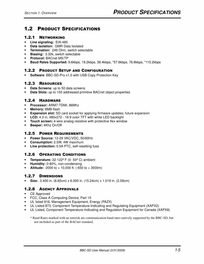
1.2 PRODUCT SPECIFICATIONS
1.2.1 NETWORKING
Line signaling: EIA-485
Data isolation: GMR Data Isolated
Termination: 249 Ohm, switch selectable
Biasing: 3.32k, switch selectable
Protocol: BACnet MS/TP
Baud Rates Supported: 9.6kbps, 19.2kbps, 38.4kbps, *57.6kbps, 76.8kbps, *115.2kbps
1.2.2 PRODUCT SETUP AND CONFIGURATION Software: BBC-SD-Pro v1.0 with USB Copy Protection Key
1.2.3 RESOURCES Data Screens: up to 50 data screens
Data Slots: up to 150 addressed primitive BACnet object properties
1.2.4 HARDWARE
Processor: ARM7-TDMI, 86Mhz
Memory: 8MB-flash
Expansion slot: SD card socket for applying firmware updates; future expansion
LCD: 4.3 in, 480x272 - 16:9 color TFT with white LED backlight
Touch screen: 4-wire analog resistive with protective flex window
Beeper: 4Khz On/Off
1.2.5 POWER REQUIREMENTS Power Source: 12-29 VAC/VDC, 50/60Hz
Consumption: 2.5W, 4W maximum
Line protection: 0.5A PTC, self-resetting fuse
1.2.6 OPERATING CONDITIONS
Temperature: 32-122o F (0- 50o C) ambient
Humidity: 0-80%, non-condensing
Altitude: -2000 to + 10,000 ft. (-650 to + 3500m)
1.2.7 DIMENSIONS Size: 3.400 in. (8.65cm) x 6.000 in. (15.24cm) x 1.019 in. (2.59cm)
1.2.8 AGENCY APPROVALS CE Approved
FCC, Class A Computing Device; Part 15
UL listed 916, Management Equipment, Energy (PAZX)
UL Listed 873, Component Temperature-Indicating and Regulating Equipment (XAPX2)
UL Listed, Component Temperature-Indicating and Regulation Equipment for Canada (XAPX8)
* Baud Rates marked with an asterisk are communication baud rates natively supported by the BBC-SD, but
not included as part of the BACnet standard.
PRODUCT SPECIFICATIONS SECTION 1: OVERVIEW
1-6 BBC-SD User Manual (3/31/2009)
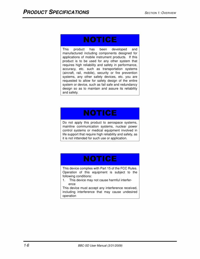
NOTICEThis product has been developed and
manufactured including components designed for
applications of mobile instrument products. If this
product is to be used for any other system that
requires high reliability and safety in performance,
accuracy, etc. such as transportation systems
(aircraft, rail, mobile), security or fire prevention
systems, any other safety devices, etc. you are
requested to allow for safety design of the entire
system or device, such as fail safe and redundancy
design so as to maintain and assure its reliability
and safety.
NOTICEDo not apply this product to aerospace systems,
mainline communication systems, nuclear power
control systems or medical equipment involved in
life support that require high reliability and safety, as
it is not inttended for such use or application.
NOTICEThis device complies with Part 15 of the FCC Rules.
Operation of this equipment is subject to the
following conditions:
1. This device may not cause harmful interfer-
ence
This device must accept any interference received,
including interference that may cause undesired
operation

SECTION 1: OVERVIEW PRODUCT SPECIFICATIONS
BBC-SD User Manual (3/31/2009) 1-7
WARNINGWARNINGWARNING
This is a Class A product. If installed in a
domestic environment, this product may cause
radio interference, in which case the user may
be required to take adequate measures.
! WARNING
QUICK START - BBC-SD SETUP SECTION 1: OVERVIEW
1-8 BBC-SD User Manual (3/31/2009)
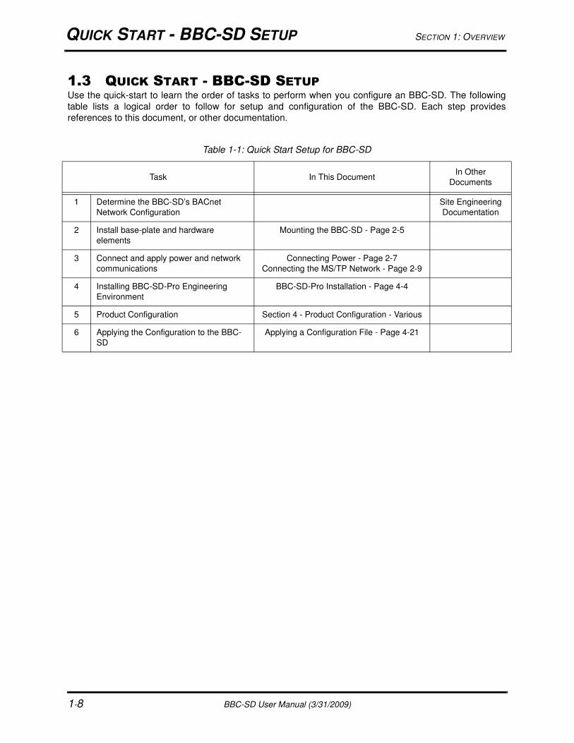
1.3 QUICK START - BBC-SD SETUPUse the quick-start to learn the order of tasks to perform when you configure an BBC-SD. The following
table lists a logical order to follow for setup and configuration of the BBC-SD. Each step provides
references to this document, or other documentation.
Table 1-1: Quick Start Setup for BBC-SD
Task In This DocumentIn Other
Documents
1 Determine the BBC-SD’s BACnet
Network Configuration
Site Engineering
Documentation
2 Install base-plate and hardware
elements
Mounting the BBC-SD - Page 2-5
3 Connect and apply power and network
communications
Connecting Power - Page 2-7
Connecting the MS/TP Network - Page 2-9
4 Installing BBC-SD-Pro Engineering
Environment
BBC-SD-Pro Installation - Page 4-4
5 Product Configuration Section 4 - Product Configuration - Various
6 Applying the Configuration to the BBC-
SD
Applying a Configuration File - Page 4-21
BBC-SD User Manual (3/31/2009) 2-1
IN THIS SECTION:Preparation............................................................................................................................................................... 2-3
Included Items..................................................................................................................................................... 2-3
Tools Required .................................................................................................................................................... 2-3
Safety Precautions................................................................................................................................................... 2-4
Mounting the BBC-SD.............................................................................................................................................. 2-5
Static Discharge Precautions .............................................................................................................................. 2-6
Disassembling the BBC-SD ................................................................................................................................ 2-6
Mounting the Back-Plate ..................................................................................................................................... 2-6
Wiring Requirements................................................................................................................................................ 2-7
Connecting Power............................................................................................................................................... 2-7
Connecting the MS/TP Network.......................................................................................................................... 2-9
Termination .................................................................................................................................................... 2-9
Biasing ........................................................................................................................................................... 2-9
Shielding ...................................................................................................................................................... 2-10
SECTION 2: WIRING & INSTALLATION
This section reviews general wiring and installation practices for the BBC-SD. Detailed information is given
to many areas including wiring for power, communications, and important safety requirements.

BBC-SD User Manual (3/31/2009) 2-2
SECTION 2: WIRING AND INSTALLATION PREPARATION
BBC-SD User Manual (3/31/2009) 2-3
2.1 PREPARATIONUnpack the BBC-SD unit and inspect the contents of the package for damaged or missing components. If
damaged, notify the appropriate carrier at once and return any damaged components for immediate repair
or replacement.
2.1.1 INCLUDED ITEMSIncluded in this package you should find the following items:
BBC-SD BACnet Touch-Screen Display unit
Two-position terminal block for MS/TP network connectivity
Two-position terminal block for line power
BBC-SD Quick-Start Guide
Field Wiring Accessories
Two (2) Ferrite Beads
One (1) EARTH Ground Lead
Optional items (if ordered)
BBC-SD-Pro Configuration Software with USB Copy Protection Key
2.1.2 TOOLS REQUIREDThe following tools and supplied may be requires for installation of the BBC-SD:
Torx screw driver: used to disassemble T-10 Torx screws from the BBC-SD housing
Small flat-blade screw driver: used for EIA-485 and Power connections
2 inch hole saw: to cut hole into wall for unit wire runs
Wire strippers: for wiring purposes
Voltage meter: for verifying power connections
The installation of the BBC-SD involves mounting the product, supplying power, and connecting to the
communications network. All wiring connections to the BBC-SD are made with the use of plug (male) &
socket (female) terminal blocks (TB). The plug consists of terminal ports and adjustment screws.The
socket consists of a row of pins and is permanently mounted to the printed circuit board (PCB).
When connecting/disconnecting the two parts of the terminal block, align the holes on the plug with the
pins on the socket and avoid twisting, as this could damage the assembly and void the product warranty.
SAFETY PRECAUTIONS SECTION 2: WIRING AND INSTALLATION
2-4 BBC-SD User Manual (3/31/2009)
2.2 SAFETY PRECAUTIONS
WARNINGWARNINGWARNING
Disconnect power to service installed product
equipment.
NOTICEThis device is only intended for use as a monitoring
and control device for BACnet MS/TP-based
building automation equipment and is not intended
for life safety applications.
! WARNING

SECTION 2: WIRING AND INSTALLATION MOUNTING THE BBC-SD
BBC-SD User Manual (3/31/2009) 2-5
2.3 MOUNTING THE BBC-SDThe BBC-SD is may be installed near the equipment it is monitoring, or at a remote location, provided that
the distance meets EIA-485 requirements (see Connecting the MS/TP Network for more details).
The housing back-plate of the BBC-SD provides pre-drilled areas for different methods of mounting the
product. Using the mounting plate, the BBC-SD can be mounted simply on a wall, on top of a US standard
2x4 junction box, or UK standard junction box. The middle of the backplate contains an open area to
accommodate the EIA-485 networking port and power port for the BBC-SD. If you are going to mount the
BBC-SD onto a wall surface, be sure to have the appropriate tools in order to do so (such as a 2 inch hole
saw). Figure 2-1 provides a reference of housing back-plate dimensions for the BBC-SD.
Figure 2-1 BBC-SD Housing Backplate Dimensions (Not to Scale)
WARNINGWARNINGWARNING
The mounting area must be free from moisture
and or leakage, and should be unobstructed by
equipment and machinery.
.2
5.8
2.3
3.2
5.3
2.5
1.3
.9
3.2
2.3
1.1
! WARNING
MOUNTING THE BBC-SD SECTION 2: WIRING AND INSTALLATION
2-6 BBC-SD User Manual (3/31/2009)
2.3.1 STATIC DISCHARGE PRECAUTIONS
Static charges can produce voltages high enough to damage electronic components. The microprocessor
and associated circuitry within the product are sensitive to static discharge. Follow these precautions while
working with the product in both disassembled and assembled modes.
Work in a static free environment
Discharge any static electricity you may have accumulated by touching a known, securely grounded
object.
Do not handle the printed circuit board (PCB) without proper protection against static discharge. Users
should handle PCB components while wearing a ground bracelet or strap (connected to Earth
ground).
2.3.2 DISASSEMBLING THE BBC-SDPrior to mounting, you will need to disassemble the BBC-SD. To do this, you will need a Torx screw driver
that accommodates size T-10 screws. To disassemble the BBC-SD, perform the following steps:
1. Carefully loosen the four (4) T-10 Torx Drive screws located at the front of the BBC-SD and remove
the cover.
2. Remove PCB component set of the BBC-SD from housing (if still installed).
3. Retain all screws, spacers, and housing components for later reassembly.
2.3.3 MOUNTING THE BACK-PLATEAs discussed earlier, the back-plate of the BBC-SD’s housing can accommodate direct wall mounting, or
mounting applications on electrical junction boxes. The back-plate includes pre-formed screw holes that
will align with drill holes located on the junction box. These screw holes are located near the middle of the
back-plate, adjacent to the cut out areas for power and network wiring.
For junction box mounting, use junction box screws to mount the back-plate.
For direct wall mounting, a keyhole-style screw hole is located on the outer left side of the back-plate,
whereas the outer right side contains a standard screw hole. The middle contains an open area that
accommodates network and power connections. To mount the back-plate onto a wall, you may draw trace
lines prior to drilling, or use the drilling template provided in this quick start guide.
WARNINGWARNINGWARNING
Follow the precautions provided for static
discharge.
NOTICEThe printed circuit board and touch-screen
hardware assembly is installed in an unconnected,
“floating” manner. Use care during assembly cycles.
! WARNING
SECTION 2: WIRING AND INSTALLATION WIRING REQUIREMENTS
BBC-SD User Manual (3/31/2009) 2-7
2.4 WIRING REQUIREMENTSFollow the recommended wiring guidelines to reduce the chance of operation and communication errors.
All EIA-485 communications networks should employ shielded, twisted pair wiring. Each twisted pair must
be individually shielded. Unshielded cables must be placed in solid metal conduit alone. Communications
wiring should not be routed together with—or close to—other wiring carrying DC switching, AC lines,
fluorescent lighting or any other RFI/electromagnetic interference (EMI)-emitting source. Failure to use
these types of conductors may result in various system communications problems such as excessive
network retries, noise susceptibility, and loss of communication.
2.4.1 CONNECTING POWER
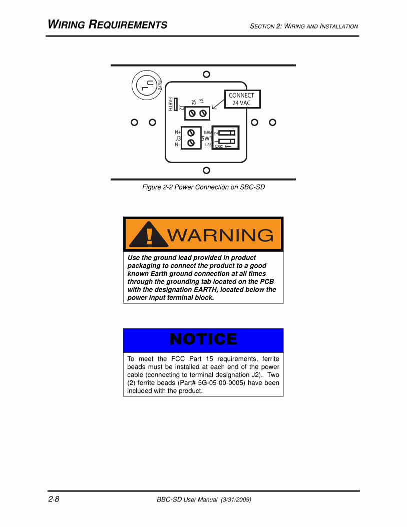
You must use a power supply capable of providing 12-29 VAC/VDC, 50/60Hz, to the BBC-SD. It is
recommended that at least 18AWG wiring be used (the terminals can accommodate 18–22AWG).
Connect power to the X1 and X2 pins located at J2. The J2 terminal is located next to the EARTH tab, as
illustrated in Figure 2-2.
WARNINGWARNINGWARNING
If you do not use proper wiring techniques, your
site may not meet Federal Communications
Commission (FCC) Class A regulations for radio
frequency interference (RFI) emissions.
WARNINGWARNINGWARNING
Disconnect main line power prior to making any
connections to the product.
! WARNING
! WARNING
WIRING REQUIREMENTS SECTION 2: WIRING AND INSTALLATION
2-8 BBC-SD User Manual (3/31/2009)
Figure 2-2 Power Connection on SBC-SD
WARNINGWARNINGWARNING
Use the ground lead provided in product
packaging to connect the product to a good
known Earth ground connection at all times
through the grounding tab located on the PCB
with the designation EARTH, located below the
power input terminal block.
NOTICETo meet the FCC Part 15 requirements, ferrite
beads must be installed at each end of the power
cable (connecting to terminal designation J2). Two
(2) ferrite beads (Part# 5G-05-00-0005) have been
included with the product.
O N1
2
EA
RT
H
X1X2
N+
N -
UL
PA
ZX
J2
J3
CONNECT
24 VAC
BIAS
TERM
SW1
! WARNING
SECTION 2: WIRING AND INSTALLATION WIRING REQUIREMENTS
BBC-SD User Manual (3/31/2009) 2-9
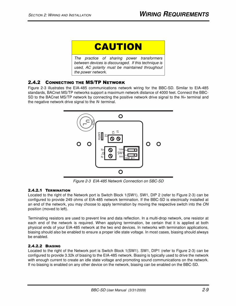
2.4.2 CONNECTING THE MS/TP NETWORK Figure 2-3 illustrates the EIA-485 communications network wiring for the BBC-SD. Similar to EIA-485
standards, BACnet MS/TP networks support a maximum network distance of 4000 feet. Connect the BBC-
SD to the BACnet MS/TP network by connecting the positive network drive signal to the N+ terminal and
the negative network drive signal to the N- terminal.
Figure 2-3 EIA-485 Network Connection on SBC-SD
2.4.2.1 TERMINATION
Located to the right of the Network port is Switch Block 1(SW1). SW1, DIP 2 (refer to Figure 2-3) can be
configured to provide 249 ohms of EIA-485 network termination. If the BBC-SD is electrically installed at
an end of the network, you may choose to apply termination by moving the respective switch into the ON
position (moved to left).
Terminating resistors are used to prevent line and data reflection. In a multi-drop network, one resistor at
each end of the network is required. When applying termination, be certain that it is applied at both
physical ends of your EIA-485 network at the two end devices. In networks with termination applications,
biasing should also be enabled to ensure a proper idle state voltage. In most cases, biasing should always
be enabled.
2.4.2.2 BIASING
Located to the right of the Network port is Switch Block 1(SW1). SW1, DIP1 (refer to Figure 2-3) can be
configured to provide 3.32k of biasing to the EIA-485 network. Biasing is typically used to drive the network
with enough current to create an idle state voltage and promoting sound communications on the network.
If no biasing is enabled on any other device on the network, biasing can be enabled on the BBC-SD.
CAUTIONThe practice of sharing power transformers
between devices is discouraged. If this technique is
used, AC polarity must be maintained throughout
the power network.
O N1
2
EA
RT
H
X1X2
UL
PA
ZX
J2
N+
N -
J3BIAS
TERM
SW1
WIRING REQUIREMENTS SECTION 2: WIRING AND INSTALLATION
2-10 BBC-SD User Manual (3/31/2009)
2.4.2.3 SHIELDING
In traditional EIA-485 standard application, the cable shield from your EIA-485 network wiring should be
tied to earth ground at the first device on the network. Each successive device on the network should have
its shield connected to the shield of the previous device. The shield of the last controller on the network
should be taped back.
NOTICEBiasing and Network Termination rules may vary
between different manufacturers of BACnet
equipment, therefore you should always consult
third-party vendor documentation regarding these
variables.
BBC-SD User Manual (3/31/2009) 3-1
IN THIS SECTION:Fundamental Concepts Overview ............................................................................................................................ 3-3
BACnet MS/TP Protocol Information................................................................................................................... 3-3
MS/TP Token Passing......................................................................................................................................... 3-3
MS/TP LAN Wiring.............................................................................................................................................. 3-3
Device Addressing .............................................................................................................................................. 3-5
Communication Rates......................................................................................................................................... 3-5
Network Optimization.......................................................................................................................................... 3-5
Client/Server Object Support ................................................................................................................................... 3-6
Client Object Support .......................................................................................................................................... 3-6
Server Object Support ........................................................................................................................................ 3-6
Device Object................................................................................................................................................. 3-6
File Object ...................................................................................................................................................... 3-6
Analog Value Object....................................................................................................................................... 3-6
Binary Value Object........................................................................................................................................ 3-7
Command Prioritization............................................................................................................................................ 3-8
Network Polling ...................................................................................................................................................... 3-10
SECTION 3: FUNDAMENTAL CONCEPTS
This section provides information on general concepts and theory that must be understood prior to setup
and configuration of the BBC-SD.

SECTION 3: FUNDAMENTAL CONCEPTS
3-2 BBC-SD User Manual (3/31/2009)
SECTION 3: FUNDAMENTAL CONCEPTS FUNDAMENTAL CONCEPTS OVERVIEW
BBC-SD User Manual (3/31/2009) 3-3
3.1 FUNDAMENTAL CONCEPTS OVERVIEWThis section of the user manual reviews standard fundamental concepts and provides an explanation of
the prerequisite information necessary to know prior to installing this product.
3.1.1 BACNET MS/TP PROTOCOL INFORMATIONBACnet MS/TP (Master Slave Token Passing) is an EIA-485 network layer intended for use with lower-
level devices such as Unitary Controllers. In comparison to BACnet/IP and BACnet/Ethernet, MS/TP is
more cost-effective to implement due to lower cost of wiring. Given the MS/TP network is a serial-based
network, devices may be configured to communicate at different baud rates specified by BACnet.
Therefore it is essential to know information regarding the BACnet network you are connecting to prior to
installing and implementing the BBC-SD.
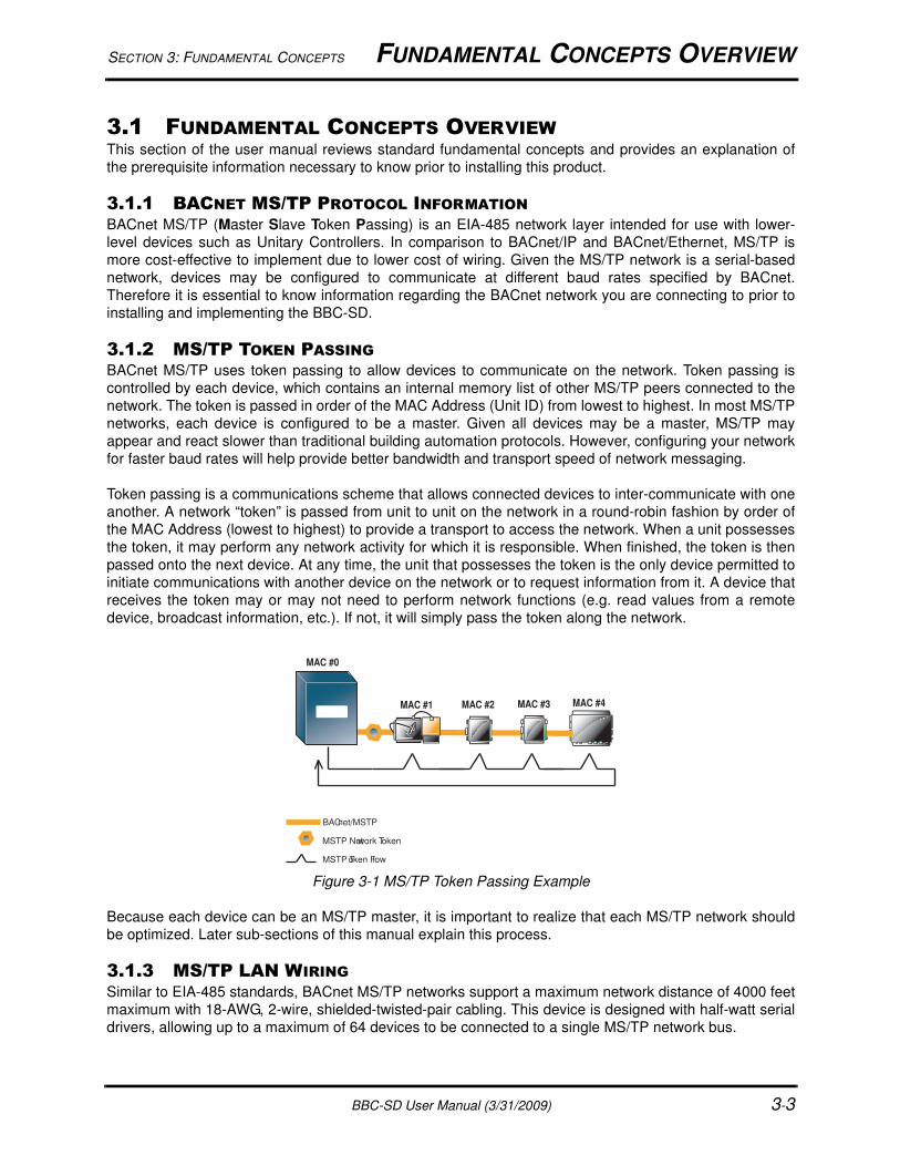
3.1.2 MS/TP TOKEN PASSINGBACnet MS/TP uses token passing to allow devices to communicate on the network. Token passing is
controlled by each device, which contains an internal memory list of other MS/TP peers connected to the
network. The token is passed in order of the MAC Address (Unit ID) from lowest to highest. In most MS/TP
networks, each device is configured to be a master. Given all devices may be a master, MS/TP may
appear and react slower than traditional building automation protocols. However, configuring your network
for faster baud rates will help provide better bandwidth and transport speed of network messaging.
Token passing is a communications scheme that allows connected devices to inter-communicate with one
another. A network “token” is passed from unit to unit on the network in a round-robin fashion by order of
the MAC Address (lowest to highest) to provide a transport to access the network. When a unit possesses
the token, it may perform any network activity for which it is responsible. When finished, the token is then
passed onto the next device. At any time, the unit that possesses the token is the only device permitted to
initiate communications with another device on the network or to request information from it. A device that
receives the token may or may not need to perform network functions (e.g. read values from a remote
device, broadcast information, etc.). If not, it will simply pass the token along the network.
Figure 3-1 MS/TP Token Passing Example
Because each device can be an MS/TP master, it is important to realize that each MS/TP network should
be optimized. Later sub-sections of this manual explain this process.
3.1.3 MS/TP LAN WIRING
Similar to EIA-485 standards, BACnet MS/TP networks support a maximum network distance of 4000 feet
maximum with 18-AWG, 2-wire, shielded-twisted-pair cabling. This device is designed with half-watt serial
drivers, allowing up to a maximum of 64 devices to be connected to a single MS/TP network bus.
BACnet/MSTP
MSTP Network Token
MAC #0
MAC #1 MAC #2 MAC #3 MAC #4
MSTP Token Flow
FUNDAMENTAL CONCEPTS OVERVIEW SECTION 3: FUNDAMENTAL CONCEPTS
3-4 BBC-SD User Manual (3/31/2009)
If you are connecting the BBC-SD to an existing MS/TP network consisting of third-party devices, consult
third-party vendor documentation regarding MS/TP network considerations.
SECTION 3: FUNDAMENTAL CONCEPTS FUNDAMENTAL CONCEPTS OVERVIEW
BBC-SD User Manual (3/31/2009) 3-5
3.1.4 DEVICE ADDRESSINGBACnet MS/TP devices contain two unique addresses. One device address is known as a Device
Instance, and the other is a MAC Address.
The Device Instance is an address assignment that is used to identify the BACnet device on a global
BACnet network. When a device is connected to a global BACnet network consisting of multiple data
layers joined together using routers, the Device Instance is used to uniquely identify the device on a global
basis. The valid range for the device instance in a BACnet device is 0 to 4,194,302. The BBC-SD must be
configured for a unique, non-conflicting Device Instance. In the event that multiple devices are assigned
the same Device Instance, both devices will simply not communicate on the BACnet network, or could be
subject to mis-directed messaging (a message intended for Device-A may be routed to Device-B)
The MAC Address is an address assignment used within the BACnet MS/TP segment to permit a device to
actively communicate on the BACnet MS/TP network. Valid MAC Address assignments range from 0 to
127 and are typically assigned in a logical and incremental order to permit faster token passing between
devices. The MAC Address of a BACnet MS/TP device must be a unique, non-conflicting value that exists
on the local MS/TP network. In the event that multiple devices are assigned with the same MAC Address,
the effects can be far more detrimental than that of a conflicting Device Instance; potentially resulting in a
failure of the entire local MS/TP network. In the event that the BBC-SD determining its MAC Address may
be a duplicate, the BBC-SD will inform the user that a duplicate MAC Address has been detected and will
not perform client communications until resolved.
3.1.5 COMMUNICATION RATESAs a serial based protocol, BACnet MS/TP supports the following four baud rates: 9.6kbps, 19.2kbps,
38.4kbps, and 76.8kbps. The BBC-SD can be configured for any of the these baud rates, as well as native
PC baud rates 57.6kbps and 115.2kbps which are currently not supported by the BACnet standard.
Each device communicating on an MS/TP network must be configured for the same baud rate at all times.
In the event that the BBC-SD’s communication baud rate is incorrect for the network it is connected to, the
BBC-SD will inform the user that a different baud rate has been detected and will not perform client
communications until resolved.
3.1.6 NETWORK OPTIMIZATION
In BACnet MS/TP devices, specific device properties are available to permit optimization of network
communications. By adjusting the Device properties max-master and max-info-frames, users can adjust
the token passing abilities of devices. The functionality of these two properties is described as follows:
Max-Master - defines the highest unit ID of a MSTP master that is connected to the network. This
value specifies to what maximum address a token may pass. For example if you have 64 devices
addressed in logical order, this value would be assigned to 64. This value should be set to the same
value across all devices connected to an MSTP network.
Max-Info-Frames - defines the amount of data frames that a MSTP master can use the token before
passing onto the next device. This value is typically set by the factory, but can be modified if neces-
sary. In the event a device does not need to keep the token for the amount of frames specified, AAM
devices will automatically pass the token onto the next device.
CLIENT/SERVER OBJECT SUPPORT SECTION 3: FUNDAMENTAL CONCEPTS
3-6 BBC-SD User Manual (3/31/2009)
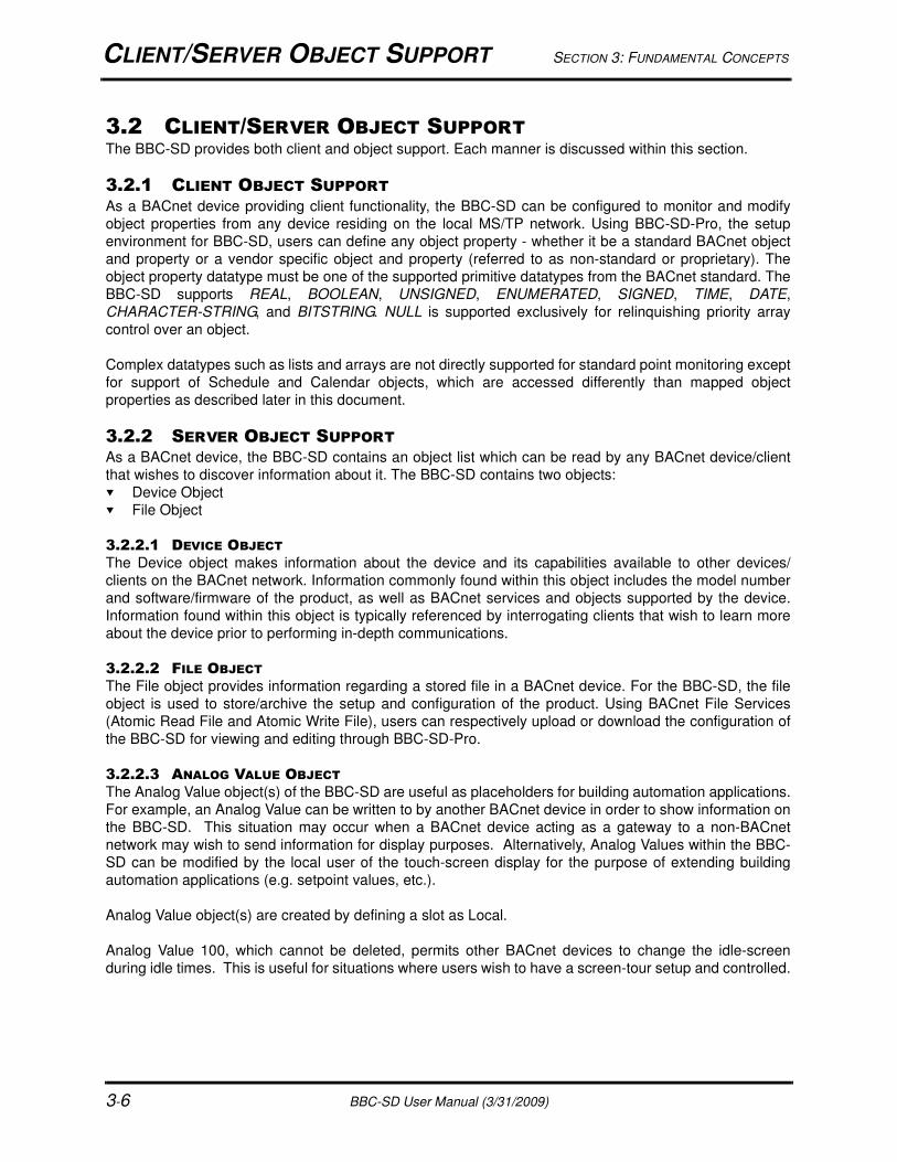
3.2 CLIENT/SERVER OBJECT SUPPORTThe BBC-SD provides both client and object support. Each manner is discussed within this section.
3.2.1 CLIENT OBJECT SUPPORTAs a BACnet device providing client functionality, the BBC-SD can be configured to monitor and modify
object properties from any device residing on the local MS/TP network. Using BBC-SD-Pro, the setup
environment for BBC-SD, users can define any object property - whether it be a standard BACnet object
and property or a vendor specific object and property (referred to as non-standard or proprietary). The
object property datatype must be one of the supported primitive datatypes from the BACnet standard. The
BBC-SD supports REAL, BOOLEAN, UNSIGNED, ENUMERATED, SIGNED, TIME, DATE,
CHARACTER-STRING, and BITSTRING. NULL is supported exclusively for relinquishing priority array
control over an object.
Complex datatypes such as lists and arrays are not directly supported for standard point monitoring except
for support of Schedule and Calendar objects, which are accessed differently than mapped object
properties as described later in this document.
3.2.2 SERVER OBJECT SUPPORTAs a BACnet device, the BBC-SD contains an object list which can be read by any BACnet device/client
that wishes to discover information about it. The BBC-SD contains two objects:
Device Object
File Object
3.2.2.1 DEVICE OBJECT
The Device object makes information about the device and its capabilities available to other devices/
clients on the BACnet network. Information commonly found within this object includes the model number
and software/firmware of the product, as well as BACnet services and objects supported by the device.
Information found within this object is typically referenced by interrogating clients that wish to learn more
about the device prior to performing in-depth communications.
3.2.2.2 FILE OBJECT
The File object provides information regarding a stored file in a BACnet device. For the BBC-SD, the file
object is used to store/archive the setup and configuration of the product. Using BACnet File Services
(Atomic Read File and Atomic Write File), users can respectively upload or download the configuration of
the BBC-SD for viewing and editing through BBC-SD-Pro.
3.2.2.3 ANALOG VALUE OBJECT
The Analog Value object(s) of the BBC-SD are useful as placeholders for building automation applications.
For example, an Analog Value can be written to by another BACnet device in order to show information on
the BBC-SD. This situation may occur when a BACnet device acting as a gateway to a non-BACnet
network may wish to send information for display purposes. Alternatively, Analog Values within the BBC-
SD can be modified by the local user of the touch-screen display for the purpose of extending building
automation applications (e.g. setpoint values, etc.).
Analog Value object(s) are created by defining a slot as Local.
Analog Value 100, which cannot be deleted, permits other BACnet devices to change the idle-screen
during idle times. This is useful for situations where users wish to have a screen-tour setup and controlled.

SECTION 3: FUNDAMENTAL CONCEPTS CLIENT/SERVER OBJECT SUPPORT
BBC-SD User Manual (3/31/2009) 3-7
3.2.2.4 BINARY VALUE OBJECT
The Binary Value object(s) of the BBC-SD are useful as placeholders for building automation applications.
For example, an Analog Value can be written to by another BACnet device in order to show information on
the BBC-SD. This situation may occur when a BACnet device acting as a gateway to a non-BACnet
network may wish to send information for display purposes. Alternatively, Binary Values within the BBC-
SD can be modified by the local user of the touch-screen display for the purpose of extending building
automation applications (e.g. start/stop commands, etc.).
COMMAND PRIORITIZATION SECTION 3: FUNDAMENTAL CONCEPTS
3-8 BBC-SD User Manual (3/31/2009)
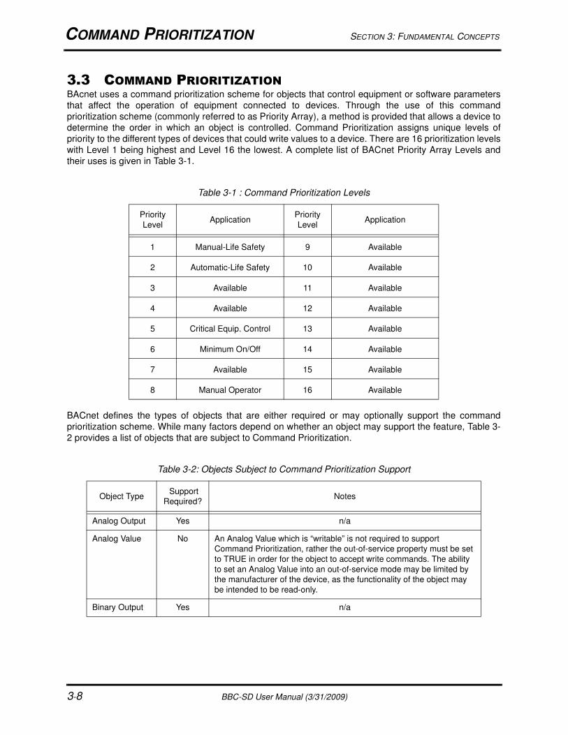
3.3 COMMAND PRIORITIZATIONBAcnet uses a command prioritization scheme for objects that control equipment or software parameters
that affect the operation of equipment connected to devices. Through the use of this command
prioritization scheme (commonly referred to as Priority Array), a method is provided that allows a device to
determine the order in which an object is controlled. Command Prioritization assigns unique levels of
priority to the different types of devices that could write values to a device. There are 16 prioritization levels
with Level 1 being highest and Level 16 the lowest. A complete list of BACnet Priority Array Levels and
their uses is given in Table 3-1.
BACnet defines the types of objects that are either required or may optionally support the command
prioritization scheme. While many factors depend on whether an object may support the feature, Table 3-
2 provides a list of objects that are subject to Command Prioritization.
Table 3-1 : Command Prioritization Levels
Priority
LevelApplication
Priority
LevelApplication
1 Manual-Life Safety 9 Available
2 Automatic-Life Safety 10 Available
3 Available 11 Available
4 Available 12 Available
5 Critical Equip. Control 13 Available
6 Minimum On/Off 14 Available
7 Available 15 Available
8 Manual Operator 16 Available
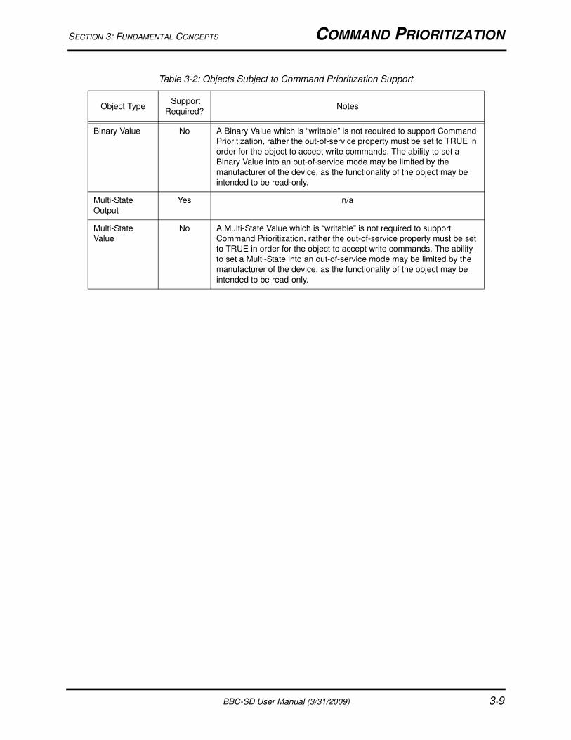
Table 3-2: Objects Subject to Command Prioritization Support
Object Type Support
Required?Notes
Analog Output Yes n/a
Analog Value No An Analog Value which is “writable” is not required to support
Command Prioritization, rather the out-of-service property must be set
to TRUE in order for the object to accept write commands. The ability
to set an Analog Value into an out-of-service mode may be limited by
the manufacturer of the device, as the functionality of the object may
be intended to be read-only.
Binary Output Yes n/a
SECTION 3: FUNDAMENTAL CONCEPTS COMMAND PRIORITIZATION
BBC-SD User Manual (3/31/2009) 3-9
Binary Value No A Binary Value which is “writable” is not required to support Command
Prioritization, rather the out-of-service property must be set to TRUE in
order for the object to accept write commands. The ability to set a
Binary Value into an out-of-service mode may be limited by the
manufacturer of the device, as the functionality of the object may be
intended to be read-only.
Multi-State
Output
Yes n/a
Multi-State
Value
No A Multi-State Value which is “writable” is not required to support
Command Prioritization, rather the out-of-service property must be set
to TRUE in order for the object to accept write commands. The ability
to set a Multi-State into an out-of-service mode may be limited by the
manufacturer of the device, as the functionality of the object may be
intended to be read-only.
Table 3-2: Objects Subject to Command Prioritization Support
Object Type Support
Required?Notes

NETWORK POLLING SECTION 3: FUNDAMENTAL CONCEPTS
3-10 BBC-SD User Manual (3/31/2009)
3.4 NETWORK POLLINGThe BBC-SD is designed to have minimal impact on a BACnet MS/TP network by actively managing the
polling of object property information. In working conditions, the BBC-SD will poll the network for data
when it needs to, rather than continuously poll and potentially reduce MS/TP network performance.
The BBC-SD will poll for point data at a reduced rate when no one is actively navigating through
configured data screens. Once a user interacts with the MS/TP network through the touch-screen display,
the product will increase its polling speed to allow “fresher” data to be displayed to the user. The polling
rates are constantly adjusted through an advanced fuzzy logic algorithm controlled by the BBC-SD.
The fuzzy logic algorithm monitors various data and network aspects. Once the data is acquired, the
algorithm will then keep all data refreshed as often as needed with preferential treatment to any variables
currently being displayed. The performance of this algorithm can be adjusted through the Polling
Aggressiveness parameter of the BBC-SD.
By default, the Polling Aggressiveness parameter is set to 5 and has been tested to be acceptable for
most monitoring applications. In applications where the BBC-SD is installed onto a communication
network that requires controlled bandwidth, the Polling Aggressiveness parameter can be lowered so that
the BBC-SD takes up less time on the network. In applications where data being displayed on the BBC-SD
is time sensitive and critical, the Polling Aggressiveness parameter can be increased to allow the BBC-SD
to poll data faster.
BBC-SD User Manual (3/31/2009) 4-1
IN THIS SECTION:Product Configuration .............................................................................................................................................. 4-3
BBC-SD-Pro System Requirements ................................................................................................................... 4-3
BBC-SD-Pro Installation........................................................................................................................................... 4-4
Starting and Using BBC-SD-Pro .............................................................................................................................. 4-9
Menu Bar Operations.......................................................................................................................................... 4-9
The Navigation Bar ............................................................................................................................................. 4-9
Data Slot Configuration .......................................................................................................................................... 4-10
Adding a Data Slot .............................................................................................................................................4-11
Defining the Data Slot ........................................................................................................................................4-11
Deleting a Data Slot .......................................................................................................................................... 4-13
Data Screen Configuration..................................................................................................................................... 4-15
Schedules Configuration........................................................................................................................................ 4-16
Extended Setup Configuration ............................................................................................................................... 4-17
Applying a Configuration File ................................................................................................................................. 4-20
Applying via Secure Digital (SD) Card .............................................................................................................. 4-20
Working with Custom XML Files ............................................................................................................................ 4-24
Creating Custom XML Files .............................................................................................................................. 4-24
SECTION 4: PRODUCT CONFIGURATION
This section provides information on how to configure the BBC-SD BACnet Touch-Screen display using
BBC-SD-Pro.

BBC-SD User Manual (3/31/2009) 4-2
SECTION 4: PRODUCT CONFIGURATION PRODUCT CONFIGURATION
BBC-SD User Manual (3/31/2009) 4-3
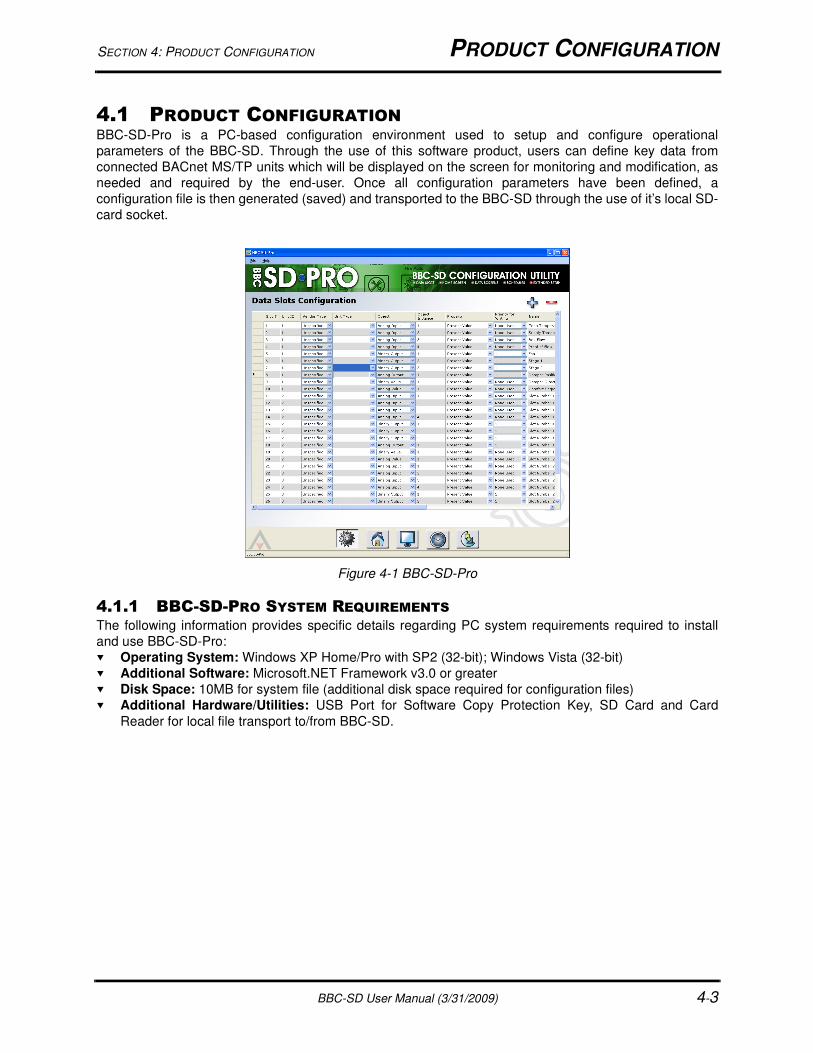
4.1 PRODUCT CONFIGURATIONBBC-SD-Pro is a PC-based configuration environment used to setup and configure operational
parameters of the BBC-SD. Through the use of this software product, users can define key data from
connected BACnet MS/TP units which will be displayed on the screen for monitoring and modification, as
needed and required by the end-user. Once all configuration parameters have been defined, a
configuration file is then generated (saved) and transported to the BBC-SD through the use of it’s local SD-
card socket.
Figure 4-1 BBC-SD-Pro
4.1.1 BBC-SD-PRO SYSTEM REQUIREMENTSThe following information provides specific details regarding PC system requirements required to install
and use BBC-SD-Pro:
Operating System: Windows XP Home/Pro with SP2 (32-bit); Windows Vista (32-bit)
Additional Software: Microsoft.NET Framework v3.0 or greater
Disk Space: 10MB for system file (additional disk space required for configuration files)
Additional Hardware/Utilities: USB Port for Software Copy Protection Key, SD Card and Card
Reader for local file transport to/from BBC-SD.

BBC-SD-PRO INSTALLATION SECTION 4: PRODUCT CONFIGURATION
4-4 BBC-SD User Manual (3/31/2009)
4.2 BBC-SD-PRO INSTALLATIONTo install BBC-SD-Pro onto your computer, you must perform the following steps:
1. Insert the BBC-SD-Pro CD into the CD drive on your computer. The InstallShield Wizard should start
automatically after a few moments. If it does not, navigate to the CD and run the setup.exe program.
2. InstallShield will examine your computer to check for an installed instance of .NET Framework v3.0. If
it is not found, you will be prompted that BBC-SD-Pro requires it to be installed on your computer. To
install the .NET Framework, click Install. This process may take a few minutes.
Figure 4-2 Requirement of .NET Framework
NOTICEPrior to software installation, do not insert the USB
Copy Protection key.
SECTION 4: PRODUCT CONFIGURATION BBC-SD-PRO INSTALLATION
BBC-SD User Manual (3/31/2009) 4-5
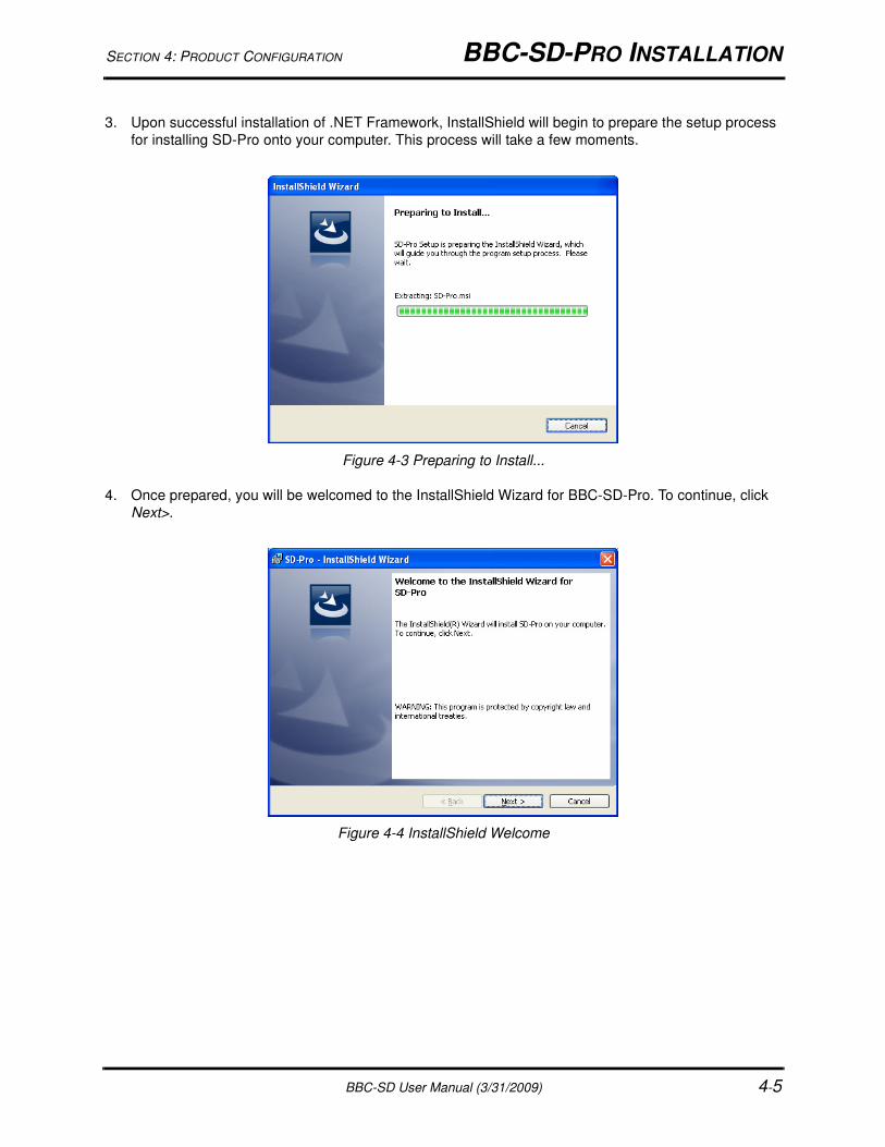
3. Upon successful installation of .NET Framework, InstallShield will begin to prepare the setup process
for installing SD-Pro onto your computer. This process will take a few moments.
Figure 4-3 Preparing to Install...
4. Once prepared, you will be welcomed to the InstallShield Wizard for BBC-SD-Pro. To continue, click
Next>.
Figure 4-4 InstallShield Welcome
BBC-SD-PRO INSTALLATION SECTION 4: PRODUCT CONFIGURATION
4-6 BBC-SD User Manual (3/31/2009)
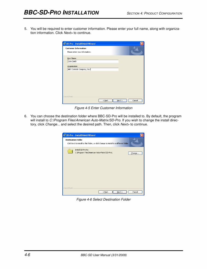
5. You will be required to enter customer information. Please enter your full name, along with organiza-
tion information. Click Next> to continue.
Figure 4-5 Enter Customer Information
6. You can choose the destination folder where BBC-SD-Pro will be installed to. By default, the program
will install to C:\Program Files\American Auto-Matrix/SD-Pro. If you wish to change the install direc-
tory, click Change... and select the desired path. Then, click Next> to continue.
Figure 4-6 Select Destination Folder
SECTION 4: PRODUCT CONFIGURATION BBC-SD-PRO INSTALLATION
BBC-SD User Manual (3/31/2009) 4-7
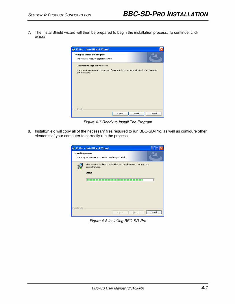
7. The InstallShield wizard will then be prepared to begin the installation process. To continue, click
Install.
Figure 4-7 Ready to Install The Program
8. InstallShield will copy all of the necessary files required to run BBC-SD-Pro, as well as configure other
elements of your computer to correctly run the process.
Figure 4-8 Installing BBC-SD-Pro
BBC-SD-PRO INSTALLATION SECTION 4: PRODUCT CONFIGURATION
4-8 BBC-SD User Manual (3/31/2009)
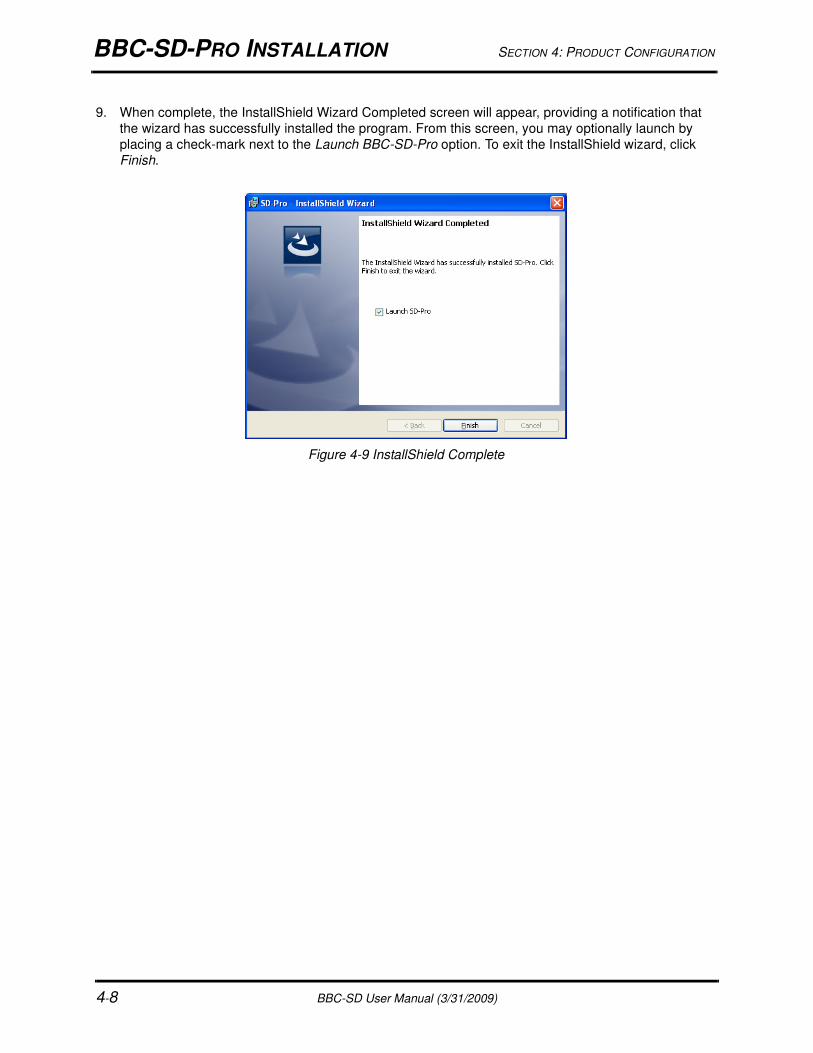
9. When complete, the InstallShield Wizard Completed screen will appear, providing a notification that
the wizard has successfully installed the program. From this screen, you may optionally launch by
placing a check-mark next to the Launch BBC-SD-Pro option. To exit the InstallShield wizard, click
Finish.
Figure 4-9 InstallShield Complete

SECTION 4: PRODUCT CONFIGURATION STARTING AND USING BBC-SD-PRO
BBC-SD User Manual (3/31/2009) 4-9
4.3 STARTING AND USING BBC-SD-PROTo start BBC-SD-Pro, perform the following steps:
1. Insert the USB Software Copy Protection key into an available USB port on your computer.
2. Navigate to Windows Start>Programs>American Auto-Matrix and select the BBC-SD-Pro icon listing
from the program menu.
4.3.1 MENU BAR OPERATIONS
BBC-SD-Pro provides a basic menu bar consisting of a File drop-down menu and a Help drop-down menu.
Table 4-1 and Table 4-2 provide a quick reference for each operation feature available through the
respective drop-down menus.
4.3.2 THE NAVIGATION BARThe layout of BBC-SD-Pro provides easy navigation and usage of programming various aspects of the
BBC-SD. Navigation to each configuration area is performed by clicking on the navigation bar, located at
the bottom of the BBC-SD-Pro window. Within the engineering environment, there are five configuration
areas which are reviewed in this manual. The configuration areas include:
Data Slot Configuration
Home Screen Configuration
Data Screen Configuration
Schedules
Extended Setup
Table 4-1: File Drop-Down Menu
File Menu Option Shortcut Keys Operation
New CTRL + N Creates a new, blank configuration file template.
Open CTRL + O Provides the capability to load an existing
configuration file saved on the local PC or a
removable storage drive.
Save CTRL + S Allows the user to save changes to a
configuration currently opened for editing.
Save As Allows the user to save a configuration currently
opened for editing, but also permits the user to
choose the destination of where the configuration
file is saved to.
Exit Closes and terminates the BBC-SD-Pro program.
Table 4-2: Help Drop-Down Menu
Help Menu Option Shortcut Keys Operation
About Provides information about the program name
and revision and any copyright information
associated with it.
DATA SLOT CONFIGURATION SECTION 4: PRODUCT CONFIGURATION
4-10 BBC-SD User Manual (3/31/2009)
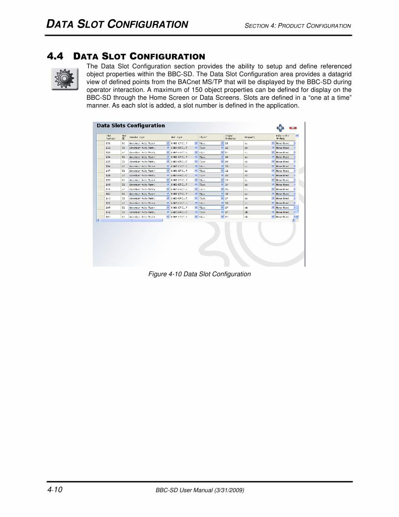
4.4 DATA SLOT CONFIGURATIONThe Data Slot Configuration section provides the ability to setup and define referenced
object properties within the BBC-SD. The Data Slot Configuration area provides a datagrid
view of defined points from the BACnet MS/TP that will be displayed by the BBC-SD during
operator interaction. A maximum of 150 object properties can be defined for display on the
BBC-SD through the Home Screen or Data Screens. Slots are defined in a “one at a time”
manner. As each slot is added, a slot number is defined in the application.
Figure 4-10 Data Slot Configuration

SECTION 4: PRODUCT CONFIGURATION DATA SLOT CONFIGURATION
BBC-SD User Manual (3/31/2009) 4-11
4.4.1 ADDING A DATA SLOTTo add a slot, either right-click in the slot configuration area and select New from the shortcut menu, or
click the button located on the top right hand side of the Slot Configuration window.
Figure 4-11 Adding a Data Slot
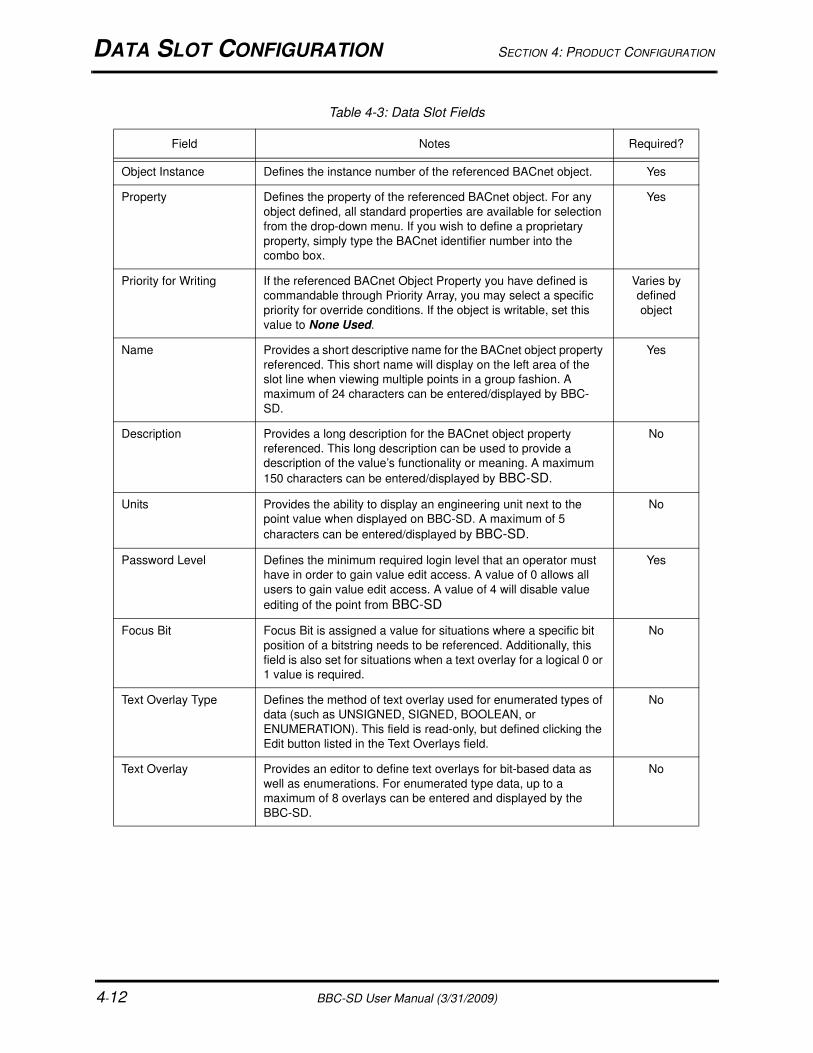
4.4.2 DEFINING THE DATA SLOTA new slot with a slot number will be added to the form. From this point, you will then be required to specify
field information regarding the object property you wish to reference in the BBC-SD. While most field
information is required, a few parameters are optional. Table 4-3 provides a complete description of each
field, its usage, and whether or not a value is required.
Table 4-3: Data Slot Fields
Field Notes Required?
Slot Number Defines the slot number of the referenced object property. The
first slot typically starts with the number 1 and works in an
incremental fashion. If an intermediate slot is deleted, the slot
number is as well - thereby not affecting other slots or data
screen configurations.
Yes
Unit ID Defines the MAC Address of the BACnet MS/TP device you are
addressing. This value can be of a range from 0 - 254, where 0 -
127 is commonly reserved for MS/TP master units, and 128-254
is commonly reserved for MS/TP slave units.
The Local selection allows users to create an Analog or Binary
Value object within the BBC-SD for extended building automation
applications. A maximum of 32 Analog Values and 32 Binary
Values may be defined.
Yes
Vendor Type Provides a vendor type definition for the manufacturer of the
BACnet device you are working with. Each vendor may have a
library of static devices that contain specific object and property
information referenced in XML files as part of this program. XML
File Usage is described later in this section
No
Unit Type Provides a unit type (model) definition for the BACnet device you
are working with. Each vendor may have specific object and
property information referenced in XML files as part of this
program. XML File Usage is described later in this section
No
Object Defines the BACnet Object Type you wish to address. Standard
Objects are available from the combo-box. If you wish to define a
proprietary object, simply type the BACnet Identifier number into
the combo box.
Yes
DATA SLOT CONFIGURATION SECTION 4: PRODUCT CONFIGURATION
4-12 BBC-SD User Manual (3/31/2009)
Object Instance Defines the instance number of the referenced BACnet object. Yes
Property Defines the property of the referenced BACnet object. For any
object defined, all standard properties are available for selection
from the drop-down menu. If you wish to define a proprietary
property, simply type the BACnet identifier number into the
combo box.
Yes
Priority for Writing If the referenced BACnet Object Property you have defined is
commandable through Priority Array, you may select a specific
priority for override conditions. If the object is writable, set this
value to None Used.
Varies by
defined
object
Name Provides a short descriptive name for the BACnet object property
referenced. This short name will display on the left area of the
slot line when viewing multiple points in a group fashion. A
maximum of 24 characters can be entered/displayed by BBC-
SD.
Yes
Description Provides a long description for the BACnet object property
referenced. This long description can be used to provide a
description of the value’s functionality or meaning. A maximum
150 characters can be entered/displayed by BBC-SD.
No
Units Provides the ability to display an engineering unit next to the
point value when displayed on BBC-SD. A maximum of 5
characters can be entered/displayed by BBC-SD.
No
Password Level Defines the minimum required login level that an operator must
have in order to gain value edit access. A value of 0 allows all
users to gain value edit access. A value of 4 will disable value
editing of the point from BBC-SD
Yes
Focus Bit Focus Bit is assigned a value for situations where a specific bit
position of a bitstring needs to be referenced. Additionally, this
field is also set for situations when a text overlay for a logical 0 or
1 value is required.
No
Text Overlay Type Defines the method of text overlay used for enumerated types of
data (such as UNSIGNED, SIGNED, BOOLEAN, or
ENUMERATION). This field is read-only, but defined clicking the
Edit button listed in the Text Overlays field.
No
Text Overlay Provides an editor to define text overlays for bit-based data as
well as enumerations. For enumerated type data, up to a
maximum of 8 overlays can be entered and displayed by the
BBC-SD.
No
Table 4-3: Data Slot Fields
Field Notes Required?
SECTION 4: PRODUCT CONFIGURATION DATA SLOT CONFIGURATION
BBC-SD User Manual (3/31/2009) 4-13
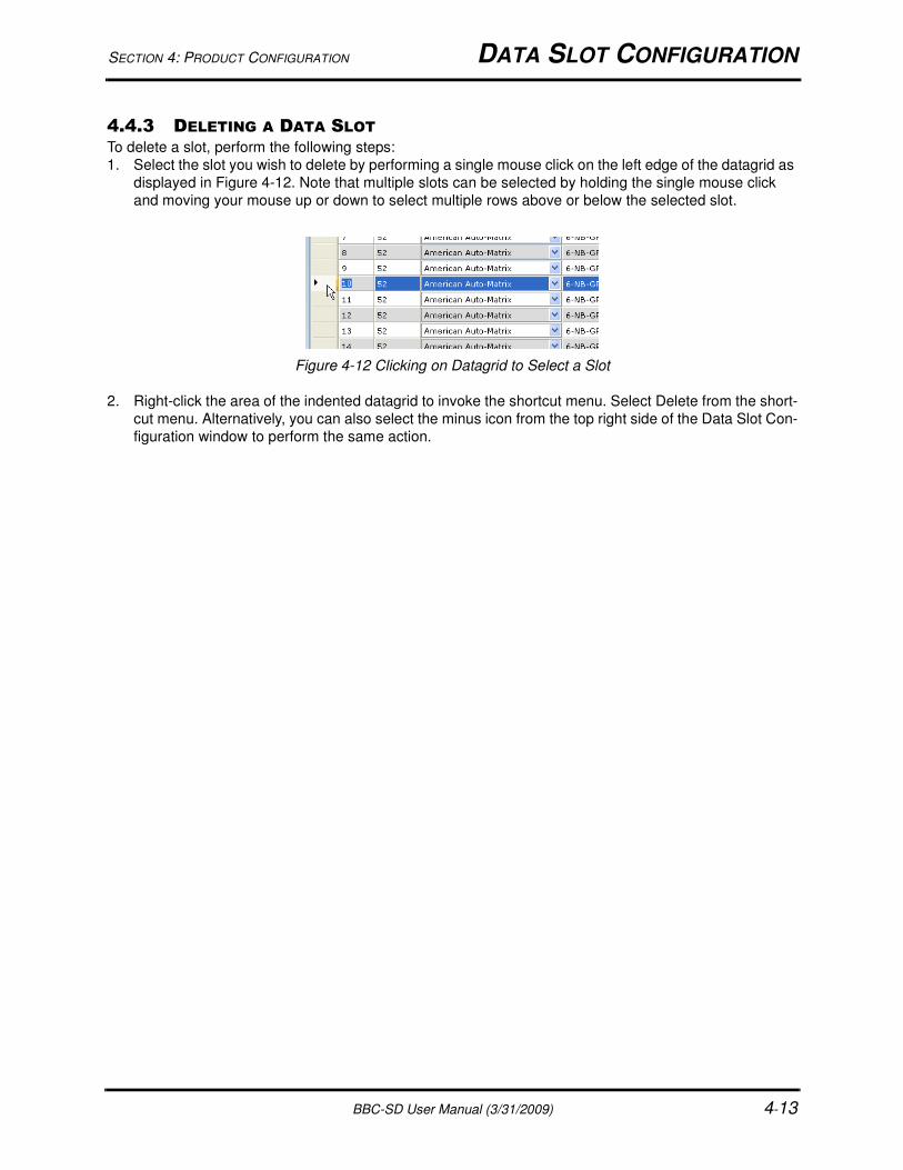
4.4.3 DELETING A DATA SLOTTo delete a slot, perform the following steps:
1. Select the slot you wish to delete by performing a single mouse click on the left edge of the datagrid as
displayed in Figure 4-12. Note that multiple slots can be selected by holding the single mouse click
and moving your mouse up or down to select multiple rows above or below the selected slot.
Figure 4-12 Clicking on Datagrid to Select a Slot
2. Right-click the area of the indented datagrid to invoke the shortcut menu. Select Delete from the short-
cut menu. Alternatively, you can also select the minus icon from the top right side of the Data Slot Con-
figuration window to perform the same action.
HOME SCREEN CONFIGURATION SECTION 4: PRODUCT CONFIGURATION
4-14 BBC-SD User Manual (3/31/2009)
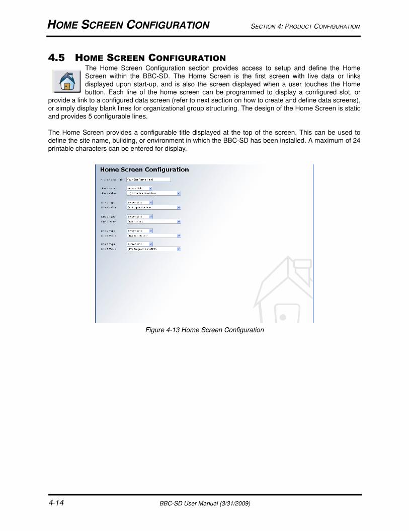
4.5 HOME SCREEN CONFIGURATIONThe Home Screen Configuration section provides access to setup and define the Home
Screen within the BBC-SD. The Home Screen is the first screen with live data or links
displayed upon start-up, and is also the screen displayed when a user touches the Home
button. Each line of the home screen can be programmed to display a configured slot, or
provide a link to a configured data screen (refer to next section on how to create and define data screens),
or simply display blank lines for organizational group structuring. The design of the Home Screen is static
and provides 5 configurable lines.
The Home Screen provides a configurable title displayed at the top of the screen. This can be used to
define the site name, building, or environment in which the BBC-SD has been installed. A maximum of 24
printable characters can be entered for display.
Figure 4-13 Home Screen Configuration
SECTION 4: PRODUCT CONFIGURATION DATA SCREEN CONFIGURATION
BBC-SD User Manual (3/31/2009) 4-15
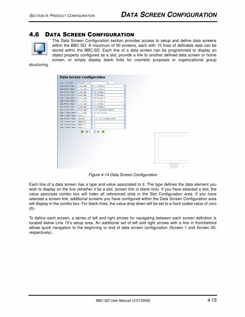
4.6 DATA SCREEN CONFIGURATIONThe Data Screen Configuration section provides access to setup and define data screens
within the BBC-SD. A maximum of 50 screens, each with 15 lines of definable data can be
stored within the BBC-SD. Each line of a data screen can be programmed to display an
object property configured as a slot, provide a link to another defined data screen or home
screen, or simply display blank links for cosmetic purposes or organizational group
structuring.
Figure 4-14 Data Screen Configuration
Each line of a data screen has a type and value associated to it. The type defines the data element you
wish to display on the line (whether it be a slot, screen link or blank line). If you have selected a slot, the
value associate combo box will index all referenced slots in the Slot Configuration area. If you have
selected a screen link, additional screens you have configured within the Data Screen Configuration area
will display in the combo box. For blank lines, the value drop down will be set to a hard coded value of zero
(0).
To define each screen, a series of left and right arrows for navigating between each screen definition is
located below Line 15’s setup area. An additional set of left and right arrows with a line in front/behind
allows quick navigation to the beginning or end of data screen configuration (Screen 1 and Screen 50,
respectively).
SCHEDULES CONFIGURATION SECTION 4: PRODUCT CONFIGURATION
4-16 BBC-SD User Manual (3/31/2009)
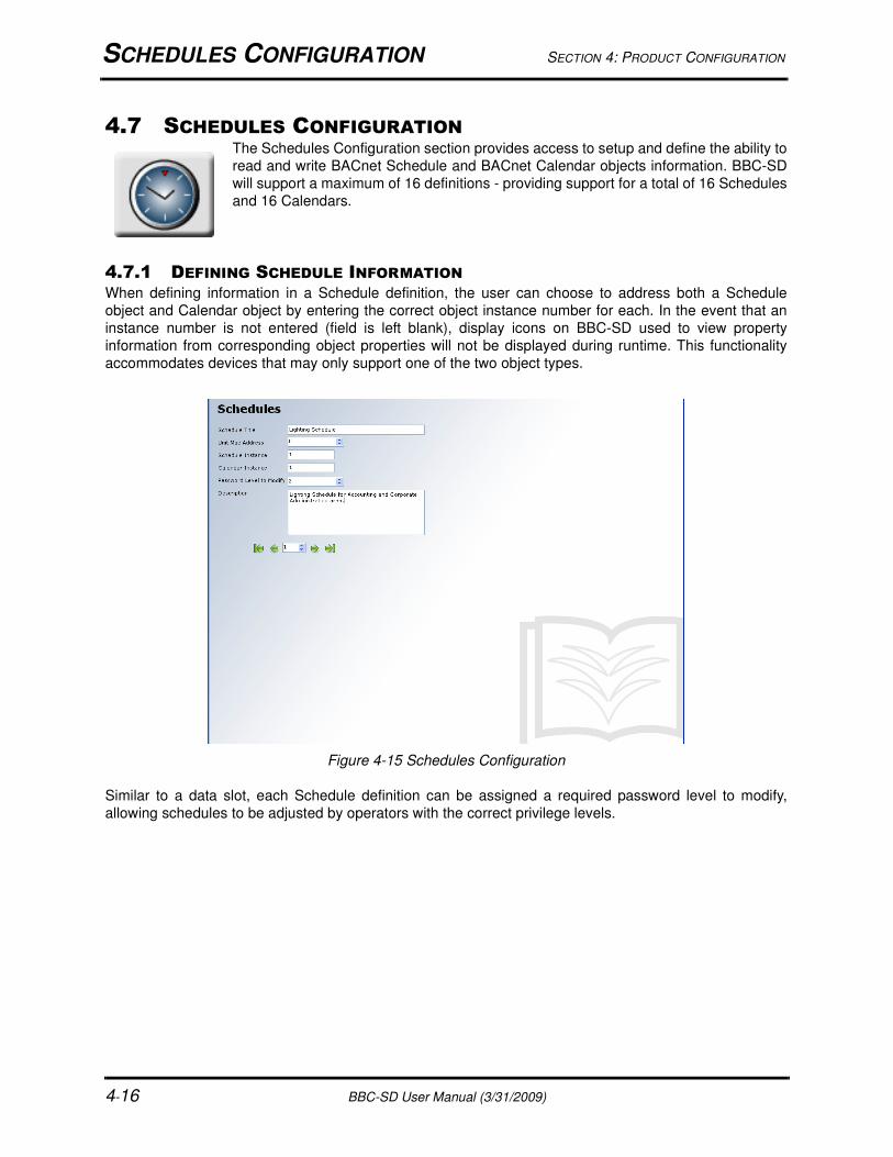
4.7 SCHEDULES CONFIGURATIONThe Schedules Configuration section provides access to setup and define the ability to
read and write BACnet Schedule and BACnet Calendar objects information. BBC-SD
will support a maximum of 16 definitions - providing support for a total of 16 Schedules
and 16 Calendars.
4.7.1 DEFINING SCHEDULE INFORMATIONWhen defining information in a Schedule definition, the user can choose to address both a Schedule
object and Calendar object by entering the correct object instance number for each. In the event that an
instance number is not entered (field is left blank), display icons on BBC-SD used to view property
information from corresponding object properties will not be displayed during runtime. This functionality
accommodates devices that may only support one of the two object types.
Figure 4-15 Schedules Configuration
Similar to a data slot, each Schedule definition can be assigned a required password level to modify,
allowing schedules to be adjusted by operators with the correct privilege levels.
SECTION 4: PRODUCT CONFIGURATION EXTENDED SETUP CONFIGURATION
BBC-SD User Manual (3/31/2009) 4-17
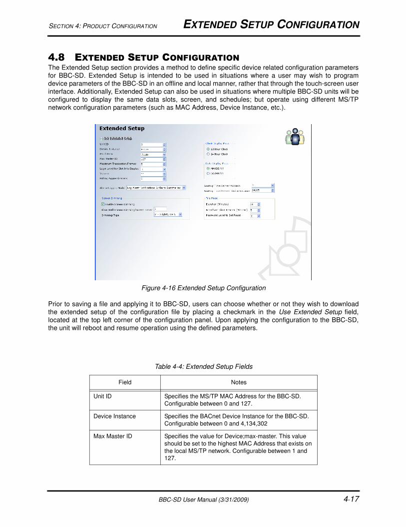
4.8 EXTENDED SETUP CONFIGURATIONThe Extended Setup section provides a method to define specific device related configuration parameters
for BBC-SD. Extended Setup is intended to be used in situations where a user may wish to program
device parameters of the BBC-SD in an offline and local manner, rather that through the touch-screen user
interface. Additionally, Extended Setup can also be used in situations where multiple BBC-SD units will be
configured to display the same data slots, screen, and schedules; but operate using different MS/TP
network configuration parameters (such as MAC Address, Device Instance, etc.).
Figure 4-16 Extended Setup Configuration
Prior to saving a file and applying it to BBC-SD, users can choose whether or not they wish to download
the extended setup of the configuration file by placing a checkmark in the Use Extended Setup field,
located at the top left corner of the configuration panel. Upon applying the configuration to the BBC-SD,
the unit will reboot and resume operation using the defined parameters.
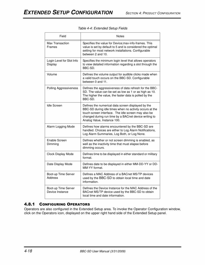
Table 4-4: Extended Setup Fields
Field Notes
Unit ID Specifies the MS/TP MAC Address for the BBC-SD.
Configurable between 0 and 127.
Device Instance Specifies the BACnet Device Instance for the BBC-SD.
Configurable between 0 and 4,134,302
Max Master ID Specifies the value for Device;max-master. This value
should be set to the highest MAC Address that exists on
the local MS/TP network. Configurable between 1 and
127.
EXTENDED SETUP CONFIGURATION SECTION 4: PRODUCT CONFIGURATION
4-18 BBC-SD User Manual (3/31/2009)
4.8.1 CONFIGURING OPERATORS
Operators are also configured in the Extended Setup area. To invoke the Operator Configuration window,
click on the Operators icon, displayed on the upper right hand side of the Extended Setup panel.
Max Transaction
Frames
Specifies the value for Device;max-info-frames. This
value is set by default to 5 and is considered the optimal
setting for most network installations. Configurable
between 2 and 10.
Login Level for Slot Info
Display
Specifies the minimum login level that allows operators
to view detailed information regarding a slot through the
BBC-SD.
Volume Defines the volume output for audible clicks made when
a valid touch occurs on the BBC-SD. Configurable
between 0 and 11.
Polling Aggressiveness Defines the aggressiveness of data refresh for the BBC-
SD. The value can be set as low as 1 or as high as 10.
The higher the value, the faster data is polled by the
BBC-SD.
Idle Screen Defines the numerical data screen displayed by the
BBC-SD during idle times when no activity occurs at the
touch-screen interface. The idle screen may also be
changed during run time by a BACnet device writing to
Analog Value, Instance 100.
Alarm Logging Mode Defines how alarms encountered by the BBC-SD are
handled. Choices are either to Log Alarm Notifications,
Log Alarm Summaries, Log Both, or Log None.
Enable Screen
Dimming
Defines whether or not screen dimming is enabled, as
well as the inactivity time that must elapse before
dimming occurs.
Clock Display Mode Defines time to be displayed in either standard or military
format.
Date Display Mode Defines date to be displayed in either MM-DD-YY or DD-
MM-YY format.
Boot-up Time Server
Address
Defines a MAC Address of a BACnet MS/TP devices
used by the BBC-SD to obtain local time and date
information.
Boot-up Time Server
Device Instance
Defines the Device Instance for the MAC Address of the
BACnet MS/TP device used by the BBC-SD to obtain
local time and date information.
Table 4-4: Extended Setup Fields
Field Notes

SECTION 4: PRODUCT CONFIGURATION EXTENDED SETUP CONFIGURATION
BBC-SD User Manual (3/31/2009) 4-19
Figure 4-17 Operators Icon
The BBC-SD supports a maximum of 8 defined operators, each with their own configurable login password
and assignable privilege level that can be used to invoke write capabilities to points, as well as access
advanced areas of the BBC-SD touch-screen user interface. Operator passwords can be assigned any
value from 0 to 99999. A login level can also be configured for each operator, where 1 is the lowest level
and 3 is the highest level. A login level of zero disables a user from logon capabilities.
Figure 4-18 Operator Configuration

APPLYING A CONFIGURATION FILE SECTION 4: PRODUCT CONFIGURATION
4-20 BBC-SD User Manual (3/31/2009)
4.9 APPLYING A CONFIGURATION FILEApplying a configuration file to the BBC-SD can be done through either BACnet File Services or through
local transfer methods using an Secure Digital (SD) card. While the process for using BACnet File
Services may vary depending on the software vendor, the method for SD Card transfer is discussed in this
document.
4.9.1 APPLYING VIA SECURE DIGITAL (SD) CARDAn BBC-SD configuration file can be downloaded to an BBC-SD hardware by transferring the saved BBC-
SD configuration file from your computer to a SD-card. Once transferred to the SD-card, the file can then
be loaded locally at BBC-SD through use of its on-board SD card socket and touch-screen display. Tools
requires to do this process include:
Torx Screw Drive - Size T-10
SD Memory Card - at least 4MB in size
SD Card Reader - to transfer files from computer to SD card.
First, you must transfer the configuration file from your computer to the SD card. In order for BBC-SD to
accept a configuration file from the SD card, the file must be named BBC-SD.lej, which is the default name
BBC-SD-Pro will attempt to save with.
To load the configuration file to BBC-SD, perform the following steps:
1. Carefully remove the housing cover of the BBC-SD.
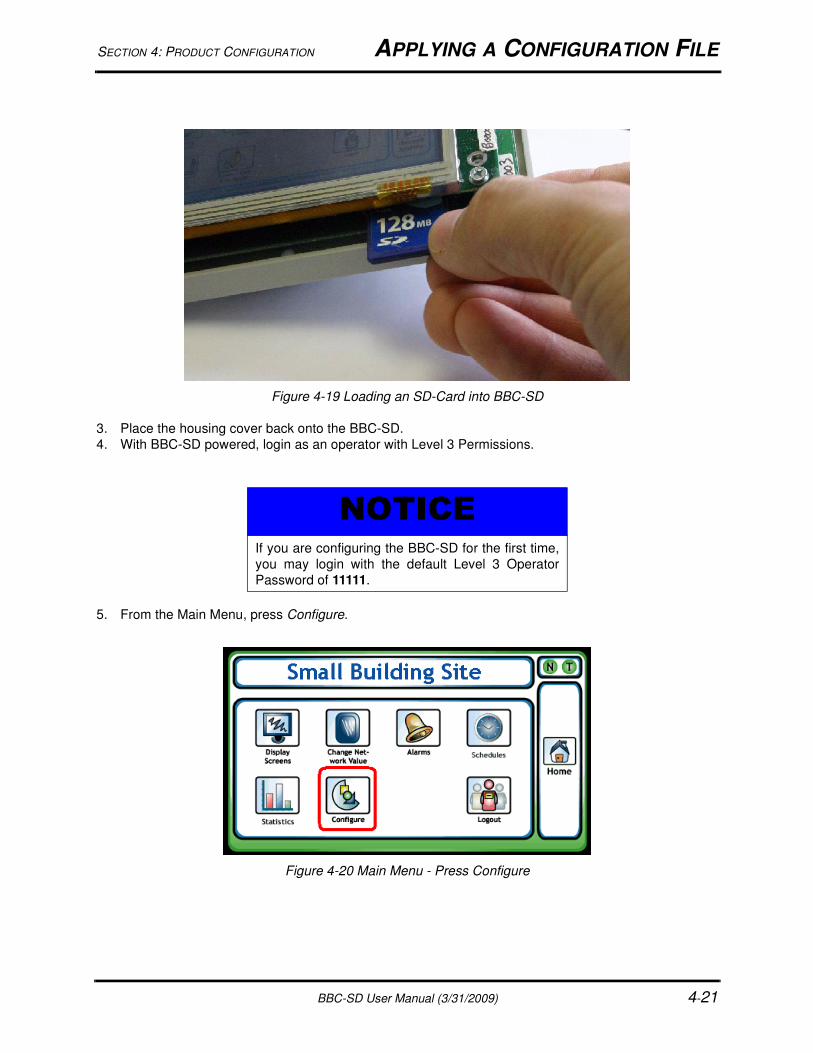
2. Locate the on-board SD card socket. It is located behind the bottom right corner of the display screen,
as shown in Figure 4-19. Insert the SD card into the socket. The card socket uses a spring-loading
mechanism to hold the card, therefore, a click noise will occur when the card is pushed up into the
socket.
NOTICEThe configuration file copied to the SD card must be
named BBC-SD.lej. If a file with a different name
exists on the SD card, the BBC-SD will not be able
to load it into its memory for runtime.
SECTION 4: PRODUCT CONFIGURATION APPLYING A CONFIGURATION FILE
BBC-SD User Manual (3/31/2009) 4-21
Figure 4-19 Loading an SD-Card into BBC-SD
3. Place the housing cover back onto the BBC-SD.
4. With BBC-SD powered, login as an operator with Level 3 Permissions.
5. From the Main Menu, press Configure.
Figure 4-20 Main Menu - Press Configure
NOTICEIf you are configuring the BBC-SD for the first time,
you may login with the default Level 3 Operator
Password of 11111.
APPLYING A CONFIGURATION FILE SECTION 4: PRODUCT CONFIGURATION
4-22 BBC-SD User Manual (3/31/2009)
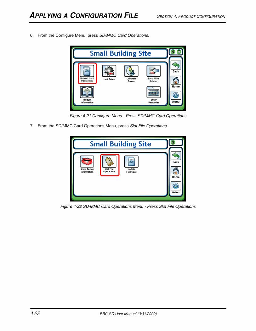
6. From the Configure Menu, press SD/MMC Card Operations.
Figure 4-21 Configure Menu - Press SD/MMC Card Operations
7. From the SD/MMC Card Operations Menu, press Slot File Operations.
Figure 4-22 SD/MMC Card Operations Menu - Press Slot File Operations
SECTION 4: PRODUCT CONFIGURATION APPLYING A CONFIGURATION FILE
BBC-SD User Manual (3/31/2009) 4-23
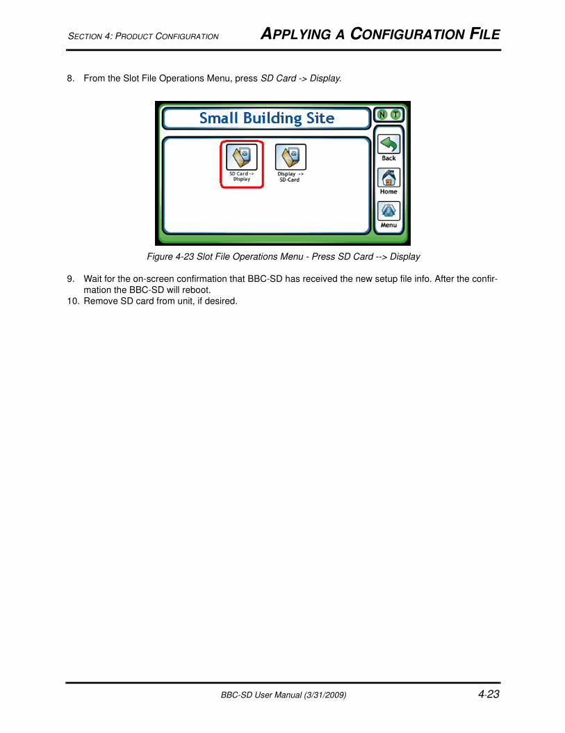
8. From the Slot File Operations Menu, press SD Card -> Display.
Figure 4-23 Slot File Operations Menu - Press SD Card --> Display
9. Wait for the on-screen confirmation that BBC-SD has received the new setup file info. After the confir-
mation the BBC-SD will reboot.
10. Remove SD card from unit, if desired.
WORKING WITH CUSTOM XML FILES SECTION 4: PRODUCT CONFIGURATION
4-24 BBC-SD User Manual (3/31/2009)
4.10 WORKING WITH CUSTOM XML FILESAs mentioned earlier in Slot Configuration, BBC-SD-Pro’s functionality provides extended capabilities in
defining controller profiles for third-party devices that contain proprietary objects and properties. While
numeric entry of proprietary objects and properties will always work, XML files can be used to add text
interpretations of custom third-party features addressed through such use. All XML files used to reference
BACnet objects and properties are located in the XML directory of the installed path for BBC-SD-Pro
(commonly C:\Program Files\American Auto-Matrix\SD-Pro). The following table provides a brief
description of default files loaded during installation.
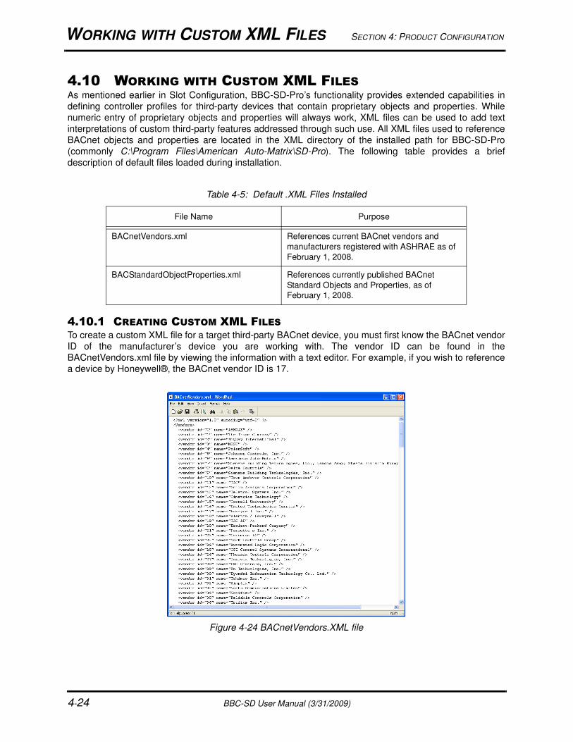
4.10.1 CREATING CUSTOM XML FILESTo create a custom XML file for a target third-party BACnet device, you must first know the BACnet vendor
ID of the manufacturer’s device you are working with. The vendor ID can be found in the
BACnetVendors.xml file by viewing the information with a text editor. For example, if you wish to reference
a device by Honeywell®, the BACnet vendor ID is 17.
Figure 4-24 BACnetVendors.XML file
Table 4-5: Default .XML Files Installed
File Name Purpose
BACnetVendors.xml References current BACnet vendors and
manufacturers registered with ASHRAE as of
February 1, 2008.
BACStandardObjectProperties.xml References currently published BACnet
Standard Objects and Properties, as of
February 1, 2008.
SECTION 4: PRODUCT CONFIGURATION WORKING WITH CUSTOM XML FILES
BBC-SD User Manual (3/31/2009) 4-25
Once you have obtained the vendor ID, you may then proceed to create an XML file for the vendor, based
on the format of the XML files. To link the vendor ID with the Vendor Type drop-down, the XML file must be
named in a format beginning with the vendor ID, followed by a hyphen and a description of the unit. For
example, if you are working with a VAV type device from Honeywell, you could name the file 17-
HoneywellVAV.xml.
The format of the XML file must be kept consistent through design and creation. There are multiple areas
that should be paid attention to when designing your file. Below is an example.
<?xml version="1.0"?>
<ProprietaryInformation>
<controller ModelName="VAVController">
<Objtype ID="0" name="analog-input" proprietary="0">
<properties instancerangestart="0" instancerangestop="0">
<property name="SensorType" id="15000" datatype="2" access="RW" />
<property name="InputOffset" id="15001" datatype="4" access="RW” />
<property name="AlarmApplication" id="15002" datatype="2" access="RW” />
</properties>
<properties instancerangestart="1" instancerangestop="1">
<property name="SensorType" id="15000" datatype="2" access="RW" />
<property name="InputOffset" id="15001" datatype="4" access="RW” />
<property name="AlarmApplication" id="15002" datatype="2" access="RW” />
</properties>
<properties instancerangestart="2" instancerangestop="2">
<property name="SensorType" id="15000" datatype="2" access="RW"/>
<property name="InputOffset" id="15001" datatype="4" access="RW”/>
<property name="AlarmApplication" id="15002" datatype="2" access="RW”/>
</properties>
</Objtype>
<Objtype ID="157" name="SomeObject" proprietary="1">
<properties instancerangestart="1" instancerangestop="1">
<property name="Function1" id="15700" datatype="4" access="RW" />
<property name="Function2" id="15701" datatype="4" access="RW" />
<property name="Function3" id="15702" datatype="4" access="RW" />
<property name="Function4" id="15703" datatype="4" access="RW" />
</properties>
</Objtype>
</controller>
</ProprietaryInformation>
Once you have finished creating your XML file, copy and paste it to the XML directory. The next time BBC-
SD-Pro is started, and the vendor has been selected, the file name should become available for selection
in the Unit Type combo-box.

WORKING WITH CUSTOM XML FILES SECTION 4: PRODUCT CONFIGURATION
4-26 BBC-SD User Manual (3/31/2009)

BBC-SD User Manual (3/31/2009) 5-1
IN THIS SECTIONUsing the BBC-SD ................................................................................................................................................... 5-3
Operator Password Protection ............................................................................................................................ 5-3
Value Editing ....................................................................................................................................................... 5-4
Data Entry Methods ............................................................................................................................................ 5-5
The Home Screen.................................................................................................................................................... 5-6
Menu ........................................................................................................................................................................ 5-7
Display Screens ....................................................................................................................................................... 5-8
Alarms...................................................................................................................................................................... 5-9
Change Network Value ...........................................................................................................................................5-11
Schedules .............................................................................................................................................................. 5-12
Working with the Weekly Schedule Property .................................................................................................... 5-13
Working with the Exception Schedule Property ................................................................................................ 5-16
Working with Calendars .................................................................................................................................... 5-17
Working with Other Properties .......................................................................................................................... 5-18
Statistics ................................................................................................................................................................. 5-19
Network Statistics.............................................................................................................................................. 5-19
Diagnostics ....................................................................................................................................................... 5-20
Configure ............................................................................................................................................................... 5-21
SD/MMC Card Operations ................................................................................................................................ 5-21
Unit Setup ......................................................................................................................................................... 5-22
Network ........................................................................................................................................................ 5-22
User Interface .............................................................................................................................................. 5-23
Audio ............................................................................................................................................................ 5-23
Users............................................................................................................................................................ 5-24
Time ............................................................................................................................................................. 5-24
Alarms.......................................................................................................................................................... 5-25
Calibrate Screen ............................................................................................................................................... 5-25
Save All & Reboot ............................................................................................................................................. 5-25
Product Information........................................................................................................................................... 5-25
Enter Passcodes............................................................................................................................................... 5-26
SECTION 5: USING THE BBC-SD
The operator interface provides an intuitive interface between an operator and the buildingautomation system. This section provides detailed information regarding each area of the BBC-
SD’s operator interface, accessed through the local touch-screen display.

SECTION 5: USING THE BBC-SD
5-2 BBC-SD User Manual (3/31/2009)
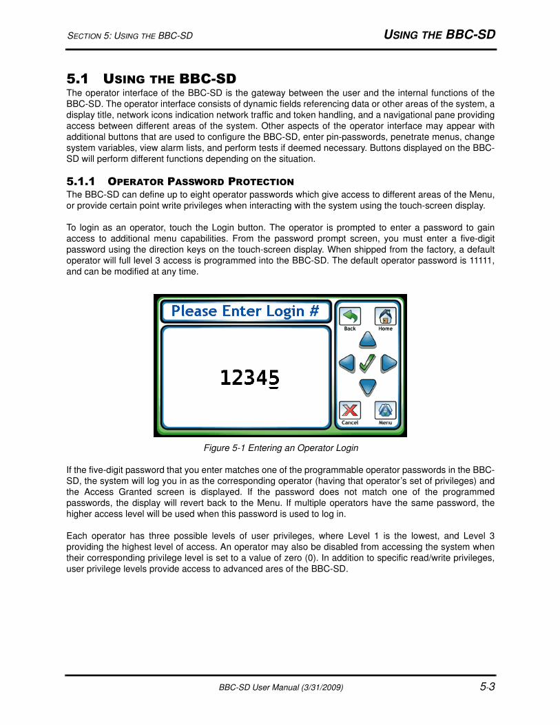
SECTION 5: USING THE BBC-SD USING THE BBC-SD
BBC-SD User Manual (3/31/2009) 5-3
5.1 USING THE BBC-SDThe operator interface of the BBC-SD is the gateway between the user and the internal functions of the
BBC-SD. The operator interface consists of dynamic fields referencing data or other areas of the system, a
display title, network icons indication network traffic and token handling, and a navigational pane providing
access between different areas of the system. Other aspects of the operator interface may appear with
additional buttons that are used to configure the BBC-SD, enter pin-passwords, penetrate menus, change
system variables, view alarm lists, and perform tests if deemed necessary. Buttons displayed on the BBC-
SD will perform different functions depending on the situation.
5.1.1 OPERATOR PASSWORD PROTECTIONThe BBC-SD can define up to eight operator passwords which give access to different areas of the Menu,
or provide certain point write privileges when interacting with the system using the touch-screen display.
To login as an operator, touch the Login button. The operator is prompted to enter a password to gain
access to additional menu capabilities. From the password prompt screen, you must enter a five-digit
password using the direction keys on the touch-screen display. When shipped from the factory, a default
operator will full level 3 access is programmed into the BBC-SD. The default operator password is 11111,
and can be modified at any time.
Figure 5-1 Entering an Operator Login
If the five-digit password that you enter matches one of the programmable operator passwords in the BBC-
SD, the system will log you in as the corresponding operator (having that operator’s set of privileges) and
the Access Granted screen is displayed. If the password does not match one of the programmed
passwords, the display will revert back to the Menu. If multiple operators have the same password, the
higher access level will be used when this password is used to log in.
Each operator has three possible levels of user privileges, where Level 1 is the lowest, and Level 3
providing the highest level of access. An operator may also be disabled from accessing the system when
their corresponding privilege level is set to a value of zero (0). In addition to specific read/write privileges,
user privilege levels provide access to advanced ares of the BBC-SD.

USING THE BBC-SD SECTION 5: USING THE BBC-SD
5-4 BBC-SD User Manual (3/31/2009)
5.1.2 VALUE EDITINGBefore explaining the different data entry methods available to operators in the BBC-SD, it is essential to
know how to edit a point value displayed on a data screen.
When navigating through different display screens, values are listed as they are programmed from top to
bottom. Each data screen can contain up to 15 elements including point values, links to other screens, and
blank lines (for cosmetic purposes). To initially view details about a point, touch the line that the point is
listed on.
Figure 5-2 Selecting a Point from a Display Screen
By touching the point listing at the display screen, an operator will be navigated to the detail screen (Figure
5-3), which provides additional information about this point. The additional information displayed in this
area is derived from slot configuration parameters. If the operator’s privilege level meets or exceeds the
priority level required to edit the slot, they can then touch the point value displayed on the details screen.
This action invokes the value editor, providing the operator a method to enter and manipulate data.
Figure 5-3 Point Details Screen
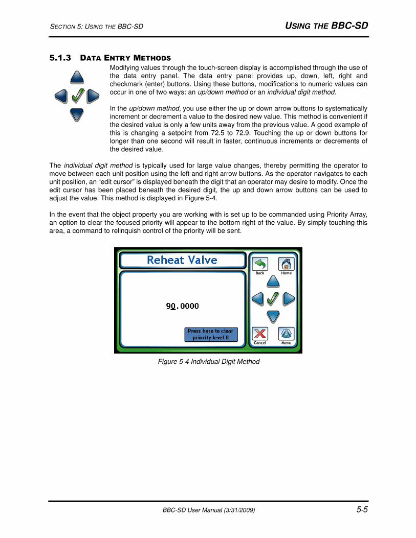
SECTION 5: USING THE BBC-SD USING THE BBC-SD
BBC-SD User Manual (3/31/2009) 5-5
5.1.3 DATA ENTRY METHODS
Modifying values through the touch-screen display is accomplished through the use of
the data entry panel. The data entry panel provides up, down, left, right and
checkmark (enter) buttons. Using these buttons, modifications to numeric values can
occur in one of two ways: an up/down method or an individual digit method.
In the up/down method, you use either the up or down arrow buttons to systematically
increment or decrement a value to the desired new value. This method is convenient if
the desired value is only a few units away from the previous value. A good example of
this is changing a setpoint from 72.5 to 72.9. Touching the up or down buttons for
longer than one second will result in faster, continuous increments or decrements of
the desired value.
The individual digit method is typically used for large value changes, thereby permitting the operator to
move between each unit position using the left and right arrow buttons. As the operator navigates to each
unit position, an “edit cursor” is displayed beneath the digit that an operator may desire to modify. Once the
edit cursor has been placed beneath the desired digit, the up and down arrow buttons can be used to
adjust the value. This method is displayed in Figure 5-4.
In the event that the object property you are working with is set up to be commanded using Priority Array,
an option to clear the focused priority will appear to the bottom right of the value. By simply touching this
area, a command to relinquish control of the priority will be sent.
Figure 5-4 Individual Digit Method
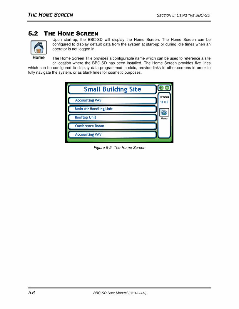
THE HOME SCREEN SECTION 5: USING THE BBC-SD
5-6 BBC-SD User Manual (3/31/2009)
5.2 THE HOME SCREENUpon start-up, the BBC-SD will display the Home Screen. The Home Screen can be
configured to display default data from the system at start-up or during idle times when an
operator is not logged in.
The Home Screen Title provides a configurable name which can be used to reference a site
or location where the BBC-SD has been installed. The Home Screen provides five lines
which can be configured to display data programmed in slots, provide links to other screens in order to
fully navigate the system, or as blank lines for cosmetic purposes.
Figure 5-5 The Home Screen
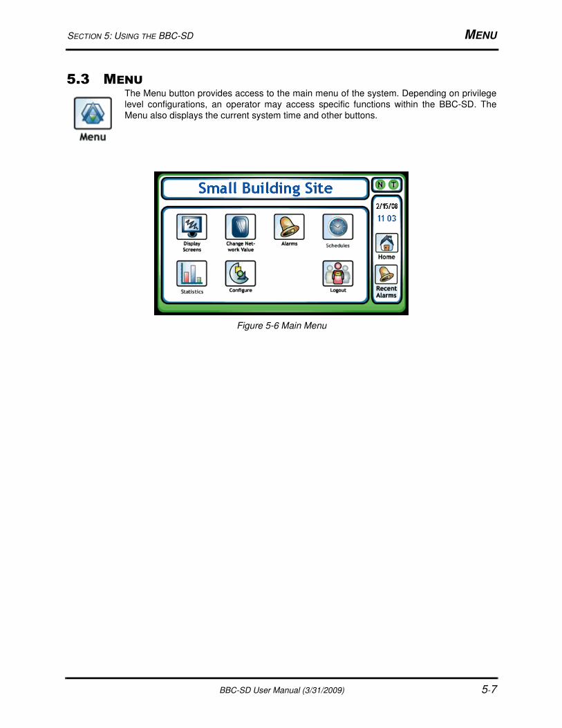
SECTION 5: USING THE BBC-SD MENU
BBC-SD User Manual (3/31/2009) 5-7
5.3 MENUThe Menu button provides access to the main menu of the system. Depending on privilege
level configurations, an operator may access specific functions within the BBC-SD. The
Menu also displays the current system time and other buttons.
Figure 5-6 Main Menu
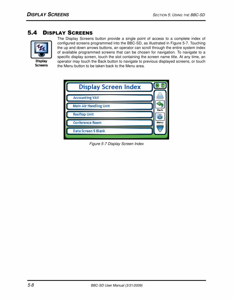
DISPLAY SCREENS SECTION 5: USING THE BBC-SD
5-8 BBC-SD User Manual (3/31/2009)
5.4 DISPLAY SCREENSThe Display Screens button provide a single point of access to a complete index of
configured screens programmed into the BBC-SD, as illustrated in Figure 5-7. Touching
the up and down arrows buttons, an operator can scroll through the entire system index
of available programmed screens that can be chosen for navigation. To navigate to a
specific display screen, touch the slot containing the screen name title. At any time, an
operator may touch the Back button to navigate to previous displayed screens, or touch
the Menu button to be taken back to the Menu area.
Figure 5-7 Display Screen Index
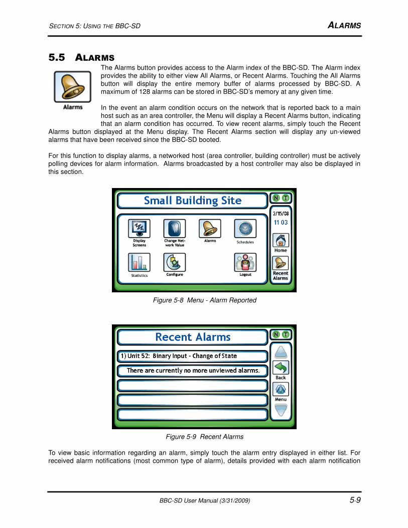
SECTION 5: USING THE BBC-SD ALARMS
BBC-SD User Manual (3/31/2009) 5-9
5.5 ALARMSThe Alarms button provides access to the Alarm index of the BBC-SD. The Alarm index
provides the ability to either view All Alarms, or Recent Alarms. Touching the All Alarms
button will display the entire memory buffer of alarms processed by BBC-SD. A
maximum of 128 alarms can be stored in BBC-SD’s memory at any given time.
In the event an alarm condition occurs on the network that is reported back to a main
host such as an area controller, the Menu will display a Recent Alarms button, indicating
that an alarm condition has occurred. To view recent alarms, simply touch the Recent
Alarms button displayed at the Menu display. The Recent Alarms section will display any un-viewed
alarms that have been received since the BBC-SD booted.
For this function to display alarms, a networked host (area controller, building controller) must be actively
polling devices for alarm information. Alarms broadcasted by a host controller may also be displayed in
this section.
Figure 5-8 Menu - Alarm Reported
Figure 5-9 Recent Alarms
To view basic information regarding an alarm, simply touch the alarm entry displayed in either list. For
received alarm notifications (most common type of alarm), details provided with each alarm notification

ALARMS SECTION 5: USING THE BBC-SD
5-10 BBC-SD User Manual (3/31/2009)
interpreted include a time and date, event state transitions, as well as other detailed parameters regarding
the occurrence.
When an operator has reviewed the information, they may touch either the Back button or Menu button to
return to another point in the system. Once an alarm has been viewed from either Alarm Menu section, it
is automatically removed from the Recent Alarms list, but can be reviewed at any time from the All Alarms
section.
Figure 5-10 Alarm Detail
NOTICEUpon logging more than 128 interpreted alarms,
BBC-SD will automatically erase the oldest alarm
entry and save the most recent alarm in the All
Alarms section.
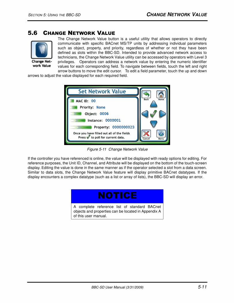
SECTION 5: USING THE BBC-SD CHANGE NETWORK VALUE
BBC-SD User Manual (3/31/2009) 5-11
5.6 CHANGE NETWORK VALUEThe Change Network Value button is a useful utility that allows operators to directly
communicate with specific BACnet MS/TP units by addressing individual parameters
such as object, property, and priority, regardless of whether or not they have been
defined as slots within the BBC-SD. Intended to provide advanced network access to
technicians, the Change Network Value utility can be accessed by operators with Level 3
privileges. Operators can address a network value by entering the numeric identifier
values for each corresponding field. To navigate between fields, touch the left and right
arrow buttons to move the edit cursor. To edit a field parameter, touch the up and down
arrows to adjust the value displayed for each required field.
Figure 5-11 Change Network Value
If the controller you have referenced is online, the value will be displayed with ready options for editing. For
reference purposes, the Unit ID, Channel, and Attribute will be displayed on the bottom of the touch-screen
display. Editing the value is done in the same manner as if the operator selected a slot from a data screen.
Similar to data slots, the Change Network Value feature will display primitive BACnet datatypes. If the
display encounters a complex datatype (such as a list or array of lists), the BBC-SD will display an error.
NOTICEA complete reference list of standard BACnet
objects and properties can be located in Appendix A
of this user manual.
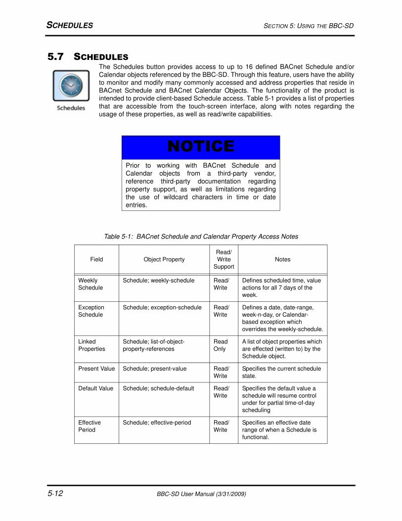
SCHEDULES SECTION 5: USING THE BBC-SD
5-12 BBC-SD User Manual (3/31/2009)
5.7 SCHEDULESThe Schedules button provides access to up to 16 defined BACnet Schedule and/or
Calendar objects referenced by the BBC-SD. Through this feature, users have the ability
to monitor and modify many commonly accessed and address properties that reside in
BACnet Schedule and BACnet Calendar Objects. The functionality of the product is
intended to provide client-based Schedule access. Table 5-1 provides a list of properties
that are accessible from the touch-screen interface, along with notes regarding the
usage of these properties, as well as read/write capabilities.
NOTICEPrior to working with BACnet Schedule and
Calendar objects from a third-party vendor,
reference third-party documentation regarding
property support, as well as limitations regarding
the use of wildcard characters in time or date
entries.
Table 5-1: BACnet Schedule and Calendar Property Access Notes
Field Object Property
Read/
Write
Support
Notes
Weekly
Schedule
Schedule; weekly-schedule Read/
Write
Defines scheduled time, value
actions for all 7 days of the
week.
Exception
Schedule
Schedule; exception-schedule Read/
Write
Defines a date, date-range,
week-n-day, or Calendar-
based exception which
overrides the weekly-schedule.
Linked
Properties
Schedule; list-of-object-
property-references
Read
Only
A list of object properties which
are effected (written to) by the
Schedule object.
Present Value Schedule; present-value Read/
Write
Specifies the current schedule
state.
Default Value Schedule; schedule-default Read/
Write
Specifies the default value a
schedule will resume control
under for partial time-of-day
scheduling
Effective
Period
Schedule; effective-period Read/
Write
Specifies an effective date
range of when a Schedule is
functional.

SECTION 5: USING THE BBC-SD SCHEDULES
BBC-SD User Manual (3/31/2009) 5-13
To access schedules, simply touch the Schedules button from the Main Menu.
5.7.1 WORKING WITH THE WEEKLY SCHEDULE PROPERTYThe weekly-schedule property of a Schedule object defines sequences of schedule actions when no
exception schedule is in effect. Providing an array for each day of the week (Monday through Sunday
respectively), the weekly-schedule can be configured to command object properties to a specific value. To
view weekly schedules, perform the following steps:
1. From the Schedule Index, select the defined schedule you wish to interrogate.
Figure 5-12 Schedule Index
Calendar Calendar; date-list Read/
Write
Specifies a list of date, date
ranges, or “week n day”
definitions (typically used in
conjunction with exception-
schedules).
Table 5-1: BACnet Schedule and Calendar Property Access Notes
Field Object Property
Read/
Write
Support
Notes
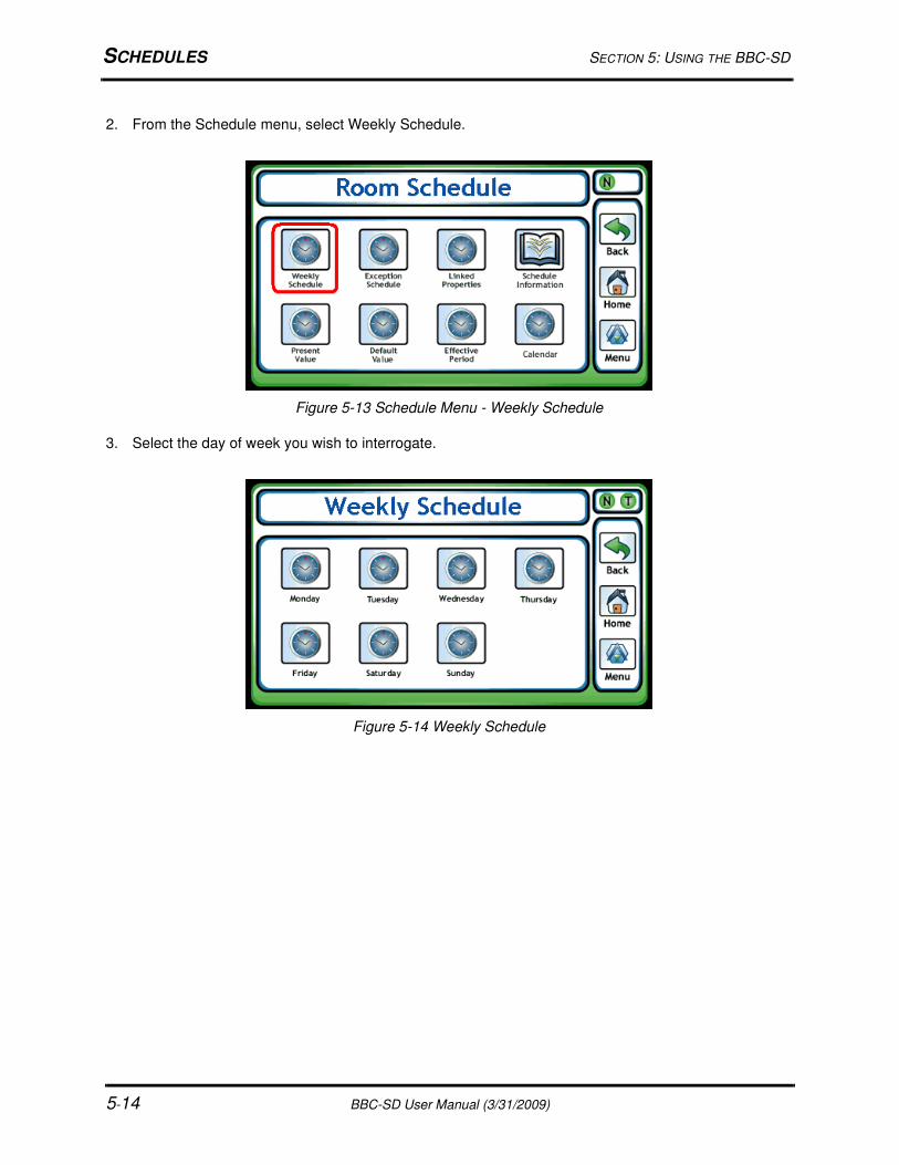
SCHEDULES SECTION 5: USING THE BBC-SD
5-14 BBC-SD User Manual (3/31/2009)
2. From the Schedule menu, select Weekly Schedule.
Figure 5-13 Schedule Menu - Weekly Schedule
3. Select the day of week you wish to interrogate.
Figure 5-14 Weekly Schedule
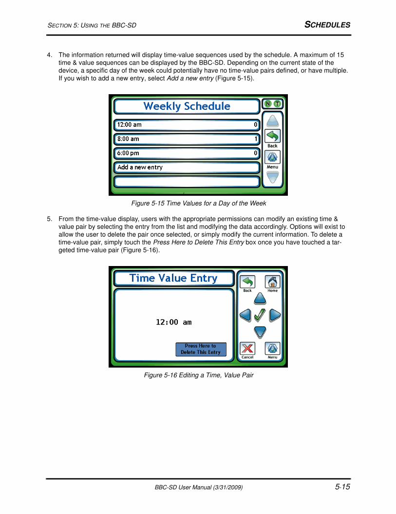
SECTION 5: USING THE BBC-SD SCHEDULES
BBC-SD User Manual (3/31/2009) 5-15
4. The information returned will display time-value sequences used by the schedule. A maximum of 15
time & value sequences can be displayed by the BBC-SD. Depending on the current state of the
device, a specific day of the week could potentially have no time-value pairs defined, or have multiple.
If you wish to add a new entry, select Add a new entry (Figure 5-15).
Figure 5-15 Time Values for a Day of the Week
5. From the time-value display, users with the appropriate permissions can modify an existing time &
value pair by selecting the entry from the list and modifying the data accordingly. Options will exist to
allow the user to delete the pair once selected, or simply modify the current information. To delete a
time-value pair, simply touch the Press Here to Delete This Entry box once you have touched a tar-
geted time-value pair (Figure 5-16).
Figure 5-16 Editing a Time, Value Pair
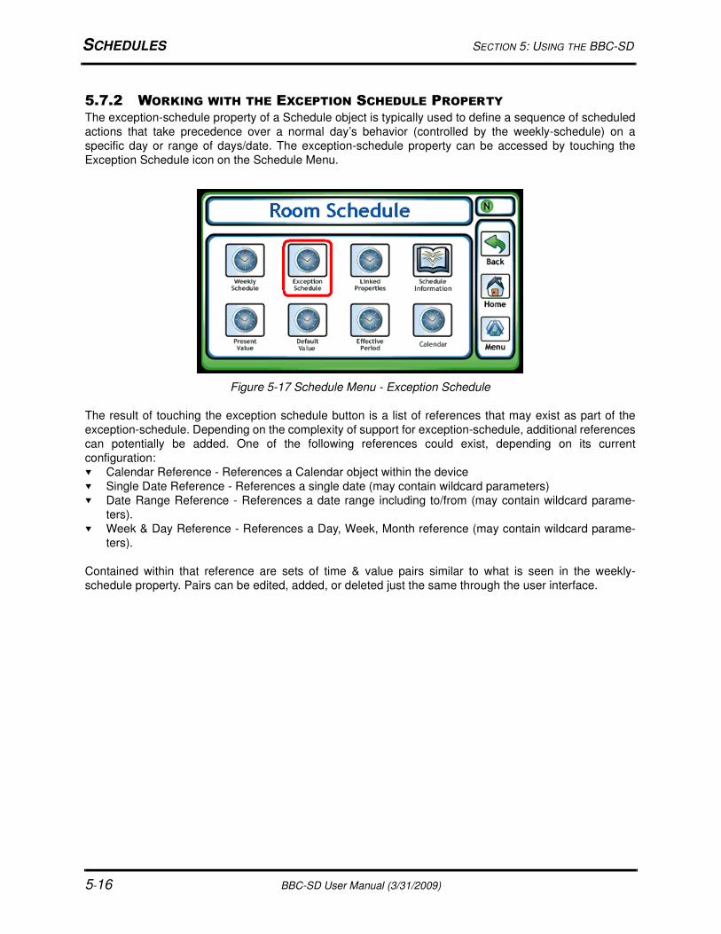
SCHEDULES SECTION 5: USING THE BBC-SD
5-16 BBC-SD User Manual (3/31/2009)
5.7.2 WORKING WITH THE EXCEPTION SCHEDULE PROPERTYThe exception-schedule property of a Schedule object is typically used to define a sequence of scheduled
actions that take precedence over a normal day’s behavior (controlled by the weekly-schedule) on a
specific day or range of days/date. The exception-schedule property can be accessed by touching the
Exception Schedule icon on the Schedule Menu.
Figure 5-17 Schedule Menu - Exception Schedule
The result of touching the exception schedule button is a list of references that may exist as part of the
exception-schedule. Depending on the complexity of support for exception-schedule, additional references
can potentially be added. One of the following references could exist, depending on its current
configuration:
Calendar Reference - References a Calendar object within the device
Single Date Reference - References a single date (may contain wildcard parameters)
Date Range Reference - References a date range including to/from (may contain wildcard parame-
ters).
Week & Day Reference - References a Day, Week, Month reference (may contain wildcard parame-
ters).
Contained within that reference are sets of time & value pairs similar to what is seen in the weekly-
schedule property. Pairs can be edited, added, or deleted just the same through the user interface.

SECTION 5: USING THE BBC-SD SCHEDULES
BBC-SD User Manual (3/31/2009) 5-17
5.7.3 WORKING WITH CALENDARSThe Calendar object is used to describe a list of calendar dates, which might be thought of as holidays,
special events, lists of dates or date ranges that can be used to affect control of parameters within the
building automation system. The BBC-SD provides access to the date-list property of a Calendar object,
allowing users to monitor/modify, and add entries to the list. A maximum of 25 entries can be displayed by
the BBC-SD. To access it, touch the Calendar icon located on the Schedule menu.
Figure 5-18 Schedule Menu - Calendar
Touching the Calendar icon returns any entries contained within the date-list property.
Figure 5-19 Calendar Date List Entries
From this area, users can select an existing entry and make modifications to any of the parameters shown
in the list, or add a new entry into the list. Available options for adding entries include:
Single Date Reference - References a single date (may contain wildcard parameters)
Date Range Reference - References a date range including to/from (may contain wildcard parame-
ters).
Week & Day Reference - References a Day, Week, Month reference (may contain wildcard parame-
ters).

SCHEDULES SECTION 5: USING THE BBC-SD
5-18 BBC-SD User Manual (3/31/2009)
5.7.4 WORKING WITH OTHER PROPERTIESOther properties accessible from the display such as Present Value, Default Value, and Effective Period
can be accessed for read/write modification purposes through the Schedule menu icons. Provided that an
operator with the appropriate permission level is logged in, the user can touch the value to edit.
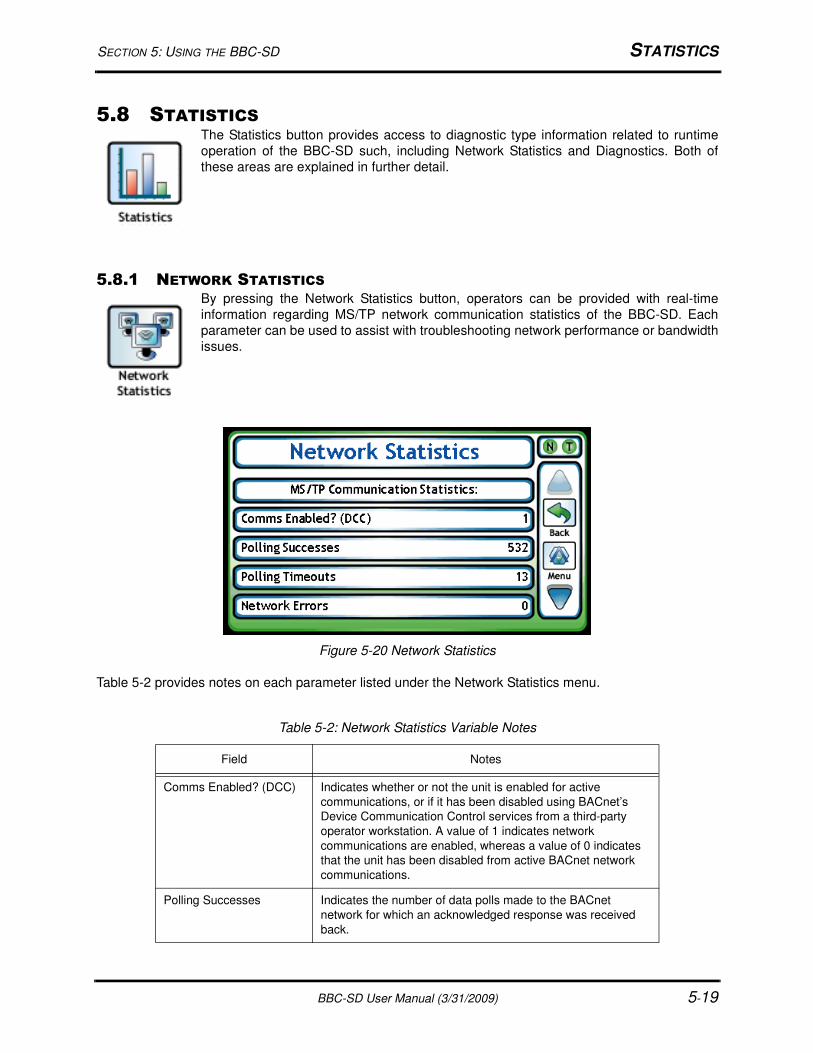
SECTION 5: USING THE BBC-SD STATISTICS
BBC-SD User Manual (3/31/2009) 5-19
5.8 STATISTICSThe Statistics button provides access to diagnostic type information related to runtime
operation of the BBC-SD such, including Network Statistics and Diagnostics. Both of
these areas are explained in further detail.
5.8.1 NETWORK STATISTICSBy pressing the Network Statistics button, operators can be provided with real-time
information regarding MS/TP network communication statistics of the BBC-SD. Each
parameter can be used to assist with troubleshooting network performance or bandwidth
issues.
Figure 5-20 Network Statistics
Table 5-2 provides notes on each parameter listed under the Network Statistics menu.
Table 5-2: Network Statistics Variable Notes
Field Notes
Comms Enabled? (DCC) Indicates whether or not the unit is enabled for active
communications, or if it has been disabled using BACnet’s
Device Communication Control services from a third-party
operator workstation. A value of 1 indicates network
communications are enabled, whereas a value of 0 indicates
that the unit has been disabled from active BACnet network
communications.
Polling Successes Indicates the number of data polls made to the BACnet
network for which an acknowledged response was received
back.
STATISTICS SECTION 5: USING THE BBC-SD
5-20 BBC-SD User Manual (3/31/2009)
5.8.2 DIAGNOSTICSThe Diagnostics button provides access to unit diagnostics. From this area, advanced
statistics regarding hardware operation, as well as key software information for the BBC-
SD. While many variables exist under the Diagnostics menu, this area is typically
accessed only under the discretion of factory technical support for advanced
troubleshooting needs during runtime operation or during field installation situations
where additional information is required from actual working units.
Polling Timeouts Indicates the number of data polls made to the BACnet
network for which no response was received back.
Network Errors Indicates the number of network errors (such as Header CRC,
and Datagram) interpreted on the network by the unit.
Avg. Age of Slot Data Indicates the average of polled Slot Data currently residing
within the unit.
Units in Ring Indicates the total number of units connected and actively
communicating (passing token, responding, etc.) on the MS/
TP network.
Active Token Passers The Active Token Passers List provides a list of MAC
Addresses known by the BBC-SD that continually pass the
token and are known to be online.
Table 5-2: Network Statistics Variable Notes
Field Notes
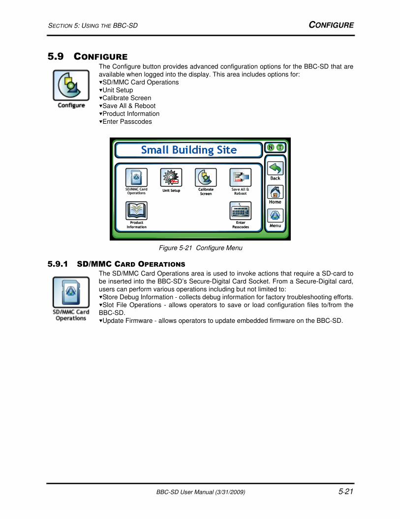
SECTION 5: USING THE BBC-SD CONFIGURE
BBC-SD User Manual (3/31/2009) 5-21
5.9 CONFIGUREThe Configure button provides advanced configuration options for the BBC-SD that are
available when logged into the display. This area includes options for:
SD/MMC Card Operations
Unit Setup
Calibrate Screen
Save All & Reboot
Product Information
Enter Passcodes
Figure 5-21 Configure Menu
5.9.1 SD/MMC CARD OPERATIONSThe SD/MMC Card Operations area is used to invoke actions that require a SD-card to
be inserted into the BBC-SD’s Secure-Digital Card Socket. From a Secure-Digital card,
users can perform various operations including but not limited to:
Store Debug Information - collects debug information for factory troubleshooting efforts.
Slot File Operations - allows operators to save or load configuration files to/from the
BBC-SD.
Update Firmware - allows operators to update embedded firmware on the BBC-SD.
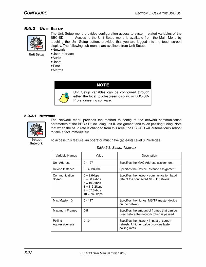
CONFIGURE SECTION 5: USING THE BBC-SD
5-22 BBC-SD User Manual (3/31/2009)
5.9.2 UNIT SETUPThe Unit Setup menu provides configuration access to system related variables of the
BBC-SD. Access to the Unit Setup menu is available from the Main Menu by
touching the Unit Setup button, provided that you are logged into the touch-screen
display. The following sub-menus are available from Unit Setup:
Network
User Interface
Audio
Users
Time
Alarms
5.9.2.1 NETWORK
The Network menu provides the method to configure the network communication
parameters of the BBC-SD; including unit ID assignment and token passing tuning. Note
that when the baud rate is changed from this area, the BBC-SD will automatically reboot
to take effect immediately.
To access this feature, an operator must have (at least) Level 3 Privileges.
NOTE
Unit Setup variables can be configured through
either the local touch-screen display, or BBC-SD-
Pro engineering software.
Table 5-3: Setup: Network
Variable Names Value Description
Unit Address 0 - 127 Specifies the MAC Address assignment.
Device Instance 0 - 4,194,302 Specifies the Device Instance assignment
Communication
Speed
0 = 9.6kbps
6 = 38.4kbps
7 = 19.2kbps
8 = 115.2kbps
9 = 57.6kbps
10 = 76.8kbps
Specifies the network communication baud
rate of the connected MS/TP network
Max Master ID 0 - 127 Specifies the highest MS/TP master device
on the network.
Maximum Frames 0-5 Specifies the amount of frames that can be
used before the network token is passed.
Polling
Aggressiveness
0-10 Specifies the network impact of screen
refresh. A higher value provides faster
polling rates.
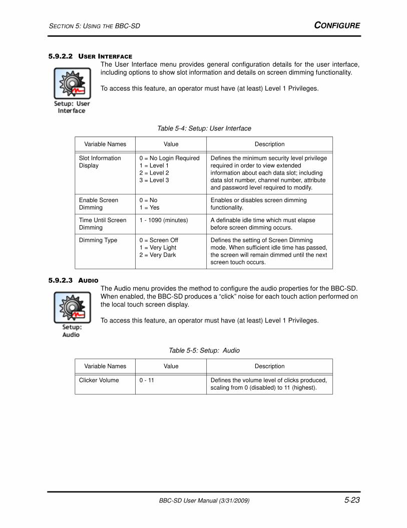
SECTION 5: USING THE BBC-SD CONFIGURE
BBC-SD User Manual (3/31/2009) 5-23
5.9.2.2 USER INTERFACE
The User Interface menu provides general configuration details for the user interface,
including options to show slot information and details on screen dimming functionality.
To access this feature, an operator must have (at least) Level 1 Privileges.
5.9.2.3 AUDIO
The Audio menu provides the method to configure the audio properties for the BBC-SD.
When enabled, the BBC-SD produces a “click” noise for each touch action performed on
the local touch screen display.
To access this feature, an operator must have (at least) Level 1 Privileges.
Table 5-4: Setup: User Interface
Variable Names Value Description
Slot Information
Display
0 = No Login Required
1 = Level 1
2 = Level 2
3 = Level 3
Defines the minimum security level privilege
required in order to view extended
information about each data slot; including
data slot number, channel number, attribute
and password level required to modify.
Enable Screen
Dimming
0 = No
1 = Yes
Enables or disables screen dimming
functionality.
Time Until Screen
Dimming
1 - 1090 (minutes) A definable idle time which must elapse
before screen dimming occurs.
Dimming Type 0 = Screen Off
1 = Very Light
2 = Very Dark
Defines the setting of Screen Dimming
mode. When sufficient idle time has passed,
the screen will remain dimmed until the next
screen touch occurs.
Table 5-5: Setup: Audio
Variable Names Value Description
Clicker Volume 0 - 11 Defines the volume level of clicks produced,
scaling from 0 (disabled) to 11 (highest).
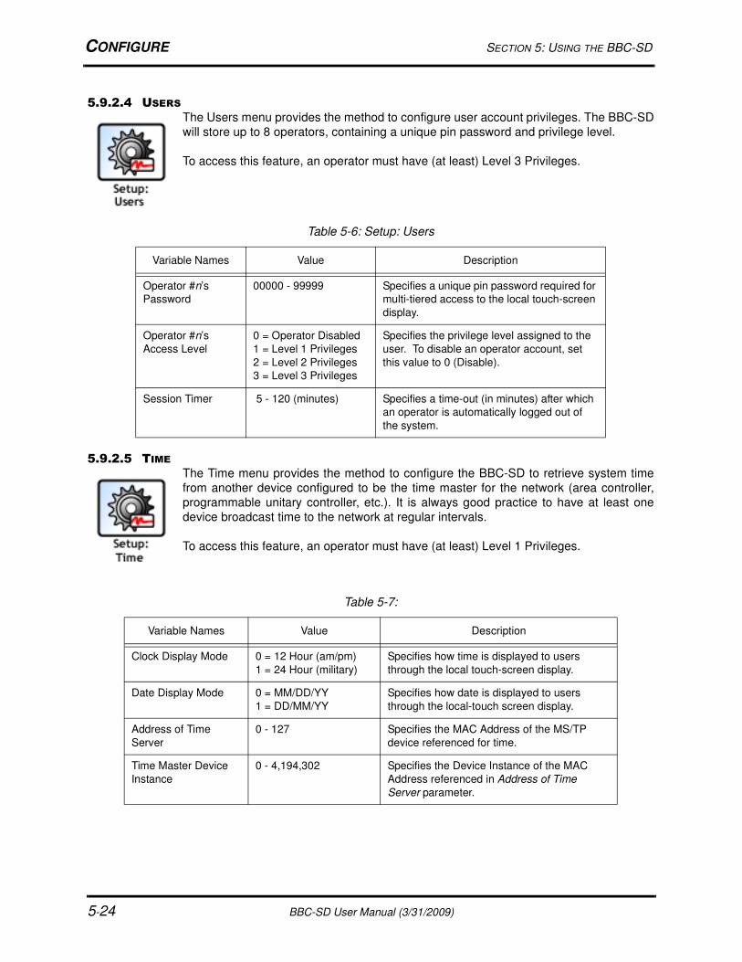
CONFIGURE SECTION 5: USING THE BBC-SD
5-24 BBC-SD User Manual (3/31/2009)
5.9.2.4 USERS
The Users menu provides the method to configure user account privileges. The BBC-SD
will store up to 8 operators, containing a unique pin password and privilege level.
To access this feature, an operator must have (at least) Level 3 Privileges.
5.9.2.5 TIME
The Time menu provides the method to configure the BBC-SD to retrieve system time
from another device configured to be the time master for the network (area controller,
programmable unitary controller, etc.). It is always good practice to have at least one
device broadcast time to the network at regular intervals.
To access this feature, an operator must have (at least) Level 1 Privileges.
Table 5-6: Setup: Users
Variable Names Value Description
Operator #n’s
Password
00000 - 99999 Specifies a unique pin password required for
multi-tiered access to the local touch-screen
display.
Operator #n’s
Access Level
0 = Operator Disabled
1 = Level 1 Privileges
2 = Level 2 Privileges
3 = Level 3 Privileges
Specifies the privilege level assigned to the
user. To disable an operator account, set
this value to 0 (Disable).
Session Timer 5 - 120 (minutes) Specifies a time-out (in minutes) after which
an operator is automatically logged out of
the system.
Table 5-7:
Variable Names Value Description
Clock Display Mode 0 = 12 Hour (am/pm)
1 = 24 Hour (military)
Specifies how time is displayed to users
through the local touch-screen display.
Date Display Mode 0 = MM/DD/YY
1 = DD/MM/YY
Specifies how date is displayed to users
through the local-touch screen display.
Address of Time
Server
0 - 127 Specifies the MAC Address of the MS/TP
device referenced for time.
Time Master Device
Instance
0 - 4,194,302 Specifies the Device Instance of the MAC
Address referenced in Address of Time
Server parameter.
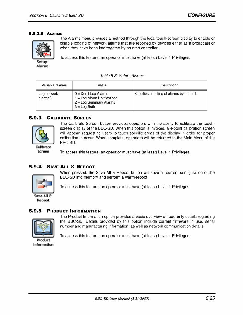
SECTION 5: USING THE BBC-SD CONFIGURE
BBC-SD User Manual (3/31/2009) 5-25
5.9.2.6 ALARMS
The Alarms menu provides a method through the local touch-screen display to enable or
disable logging of network alarms that are reported by devices either as a broadcast or
when they have been interrogated by an area controller.
To access this feature, an operator must have (at least) Level 1 Privileges.
5.9.3 CALIBRATE SCREENThe Calibrate Screen button provides operators with the ability to calibrate the touch-
screen display of the BBC-SD. When this option is invoked, a 4-point calibration screen
will appear, requesting users to touch specific areas of the display in order for proper
calibration to occur. When complete, operators will be returned to the Main Menu of the
BBC-SD.
To access this feature, an operator must have (at least) Level 1 Privileges.
5.9.4 SAVE ALL & REBOOTWhen pressed, the Save All & Reboot button will save all current configuration of the
BBC-SD into memory and perform a warm-reboot.
To access this feature, an operator must have (at least) Level 1 Privileges.
5.9.5 PRODUCT INFORMATIONThe Product Information option provides a basic overview of read-only details regarding
the BBC-SD. Details provided by this option include current firmware in use, serial
number and manufacturing information, as well as network communication details.
To access this feature, an operator must have (at least) Level 1 Privileges.
Table 5-8: Setup: Alarms
Variable Names Value Description
Log network
alarms?
0 = Don’t Log Alarms
1 = Log Alarm Notifications
2 = Log Summary Alarms
3 = Log Both
Specifies handling of alarms by the unit.
CONFIGURE SECTION 5: USING THE BBC-SD
5-26 BBC-SD User Manual (3/31/2009)
5.9.6 ENTER PASSCODESThe Enter Passcodes option is used to enter a software upgrade pass code for future
major revision updates to the product. As new upgrades are released, this section will be
expanded to include more information on this process.
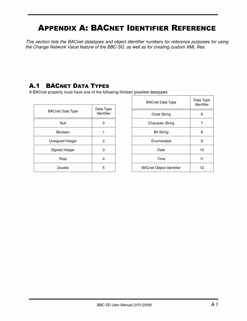
BBC-SD User Manual (3/31/2009) A-1
A.1 BACNET DATA TYPESA BACnet property must have one of the following thirteen possible datatypes
BACnet Data TypeData Type
Identifier
Null 0
Boolean 1
Unsigned Integer 2
Signed Integer 3
Real 4
Double 5
Octet String 6
Character String 7
Bit String 8
Enumerated 9
Date 10
Time 11
BACnet Object Identifier 12
BACnet Data TypeData Type
Identifier
APPENDIX A: BACNET IDENTIFIER REFERENCE
This section lists the BACnet datatypes and object identifier numbers for reference purposes for usingthe Change Network Value feature of the BBC-SD, as well as for creating custom XML files.
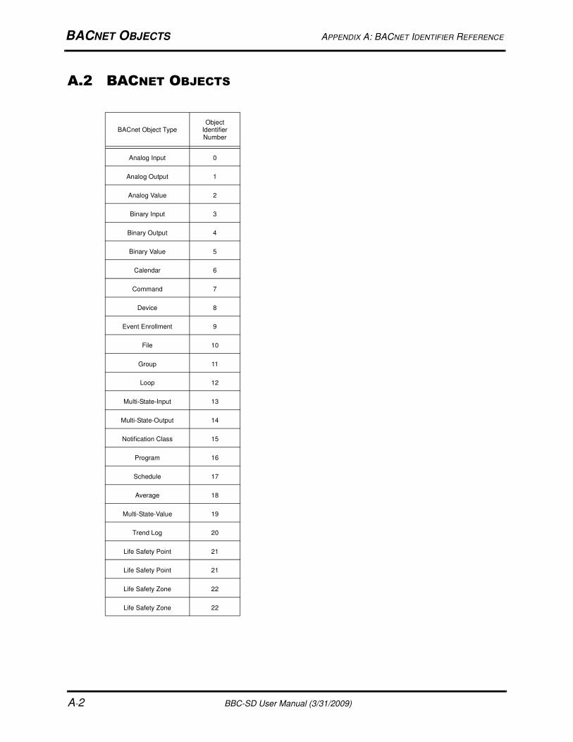
BACNET OBJECTS APPENDIX A: BACNET IDENTIFIER REFERENCE
A-2 BBC-SD User Manual (3/31/2009)
A.2 BACNET OBJECTS
BACnet Object TypeObject
Identifier Number
Analog Input 0
Analog Output 1
Analog Value 2
Binary Input 3
Binary Output 4
Binary Value 5
Calendar 6
Command 7
Device 8
Event Enrollment 9
File 10
Group 11
Loop 12
Multi-State-Input 13
Multi-State-Output 14
Notification Class 15
Program 16
Schedule 17
Average 18
Multi-State-Value 19
Trend Log 20
Life Safety Point 21
Life Safety Point 21
Life Safety Zone 22
Life Safety Zone 22
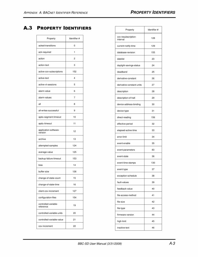
APPENDIX A: BACNET IDENTIFIER REFERENCE PROPERTY IDENTIFIERS
BBC-SD User Manual (3/31/2009) A-3
A.3 PROPERTY IDENTIFIERS
Property Identifier #
acked-transitions 0
ack-required 1
action 2
action-text 3
active-cov-subscriptions 152
active-text 4
active-vt-sessions 5
alarm-value 6
alarm-values 7
all 8
all-writes-successful 9
apdu-segment-timeout 10
apdu-timeout 11
application-software-version
12
archive 13
attempted-samples 124
average-value 125
backup-failure-timeout 153
bias 14
buffer-size 126
change-of-state-count 15
change-of-state-time 16
client-cov-increment 127
configuration-files 154
controlled-variable-reference
19
controlled-variable-units 20
controlled-variable-value 21
cov-increment 22
cov-resubscription-interval
128
current-notify-time 129
database-revision 155
datelist 23
daylight-savings-status 24
deadband 25
derivative-constant 26
derivative-constant-units 27
description 28
description-of-halt 29
device-address-binding 30
device-type 31
direct-reading 156
effective-period 32
elapsed-active-time 33
error-limit 34
event-enable 35
event-parameters 83
event-state 36
event-time-stamps 130
event-type 37
exception-schedule 38
fault-values 39
feedback-value 40
file-access-method 41
file-size 42
file-type 43
firmware-version 44
high-limit 45
inactive-text 46
Property Identifier #
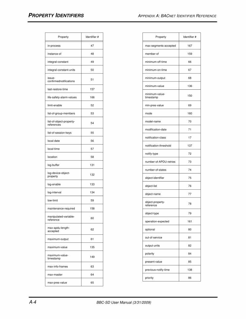
PROPERTY IDENTIFIERS APPENDIX A: BACNET IDENTIFIER REFERENCE
A-4 BBC-SD User Manual (3/31/2009)
in-process 47
instance-of 48
integral-constant 49
integral-constant-units 50
issue-confirmednotifications
51
last-restore-time 157
life-safety-alarm-values 166
limit-enable 52
list-of-group-members 53
list-of-object-property-references
54
list-of-session-keys 55
local-date 56
local-time 57
location 58
log-buffer 131
log-device-object-property
132
log-enable 133
log-interval 134
low-limit 59
maintenance-required 158
manipulated-variable-reference
60
max-apdu-length-accepted
62
maximum-output 61
maximum-value 135
maximum-value-timestamp
149
max-info-frames 63
max-master 64
max-pres-value 65
Property Identifier #
max-segments-accepted 167
member-of 159
minimum-off-time 66
minimum-on-time 67
minimum-output 68
minimum-value 136
minimum-value-timestamp
150
min-pres-value 69
mode 160
model-name 70
modification-date 71
notification-class 17
notification-threshold 137
notify-type 72
number-of-APDU-retries 73
number-of-states 74
object-identifier 75
object-list 76
object-name 77
object-property-reference
78
object-type 79
operation-expected 161
optional 80
out-of-service 81
output-units 82
polarity 84
present-value 85
previous-notify-time 138
priority 86
Property Identifier #
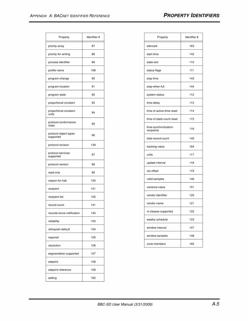
APPENDIX A: BACNET IDENTIFIER REFERENCE PROPERTY IDENTIFIERS
BBC-SD User Manual (3/31/2009) A-5
priority-array 87
priority-for-writing 88
process-identifier 89
profile-name 168
program-change 90
program-location 91
program-state 92
proportional-constant 93
proportional-constant-units
94
protocol-conformance-class
95
protocol-object-types-supported
96
protocol-revision 139
protocol-services-supported
97
protocol-version 98
read-only 99
reason-for-halt 100
recipient 101
recipient-list 102
record-count 141
records-since-notification 140
reliability 103
relinquish-default 104
required 105
resolution 106
segmentation-supported 107
setpoint 108
setpoint-reference 109
setting 162
Property Identifier #
silenced 163
start-time 142
state-text 110
status-flags 111
stop-time 143
stop-when-full 144
system-status 112
time-delay 113
time-of-active-time-reset 114
time-of-state-count-reset 115
time-synchronization-recipients
116
total-record-count 145
tracking-value 164
units 117
update-interval 118
utc-offset 119
valid-samples 146
variance-value 151
vendor-identifier 120
vendor-name 121
vt-classes-supported 122
weekly-schedule 123
window-interval 147
window-samples 148
zone-members 165
Property Identifier #

PROPERTY IDENTIFIERS APPENDIX A: BACNET IDENTIFIER REFERENCE
A-6 BBC-SD User Manual (3/31/2009)