bba cert sys 1 4973ps1i2
TRANSCRIPT

Page 1 of 17
TECHNICAL APPROVALS FOR CONSTRUCTION
APPROVAL
INSPECTION
TESTING
CERTIFICATION
Enewall Ltd4 Netherton RoadWishawLanarkshire ML2 0EQTel: 01698 373305 Fax: 01698 374503e-mail: [email protected]: www.enewall.co.uk
British Board of Agrément tel: 01923 665300Bucknalls Lane fax: 01923 665301Watford e-mail: [email protected] WD25 9BA website: www.bbacerts.co.uk©2013
The BBA is a UKAS accredited certification body — Number 113. The schedule of the current scope of accreditation for product certification is available in pdf format via the UKAS link on the BBA website at www.bbacerts.co.uk
Readers are advised to check the validity and latest issue number of this Agrément Certificate by either referring to the BBA website or contacting the BBA direct.
ENEWALL EXTERNAL WALL INSULATION SYSTEMS
ENEWALL EXTERNAL WALL INSULATION SYSTEM 1This Agrément Certificate Product Sheet(1) relates to Enewall External Wall Insulation System 1, a mechanically fixed (with supplementary adhesive when required) system, consisting of expanded polystyrene (EPS), mineral wool (MW), polyisocyanurate (PIR) or phenolic (PHS) insulation boards, glassfibre reinforcing mesh and render finishes, suitable for use on new or existing domestic and non-domestic buildings.(1) Hereinafter referred to as ‘Certificate’.
CERTIFICATION INCLUDES:• factors relating to compliance with Building Regulations
where applicable• factors relating to additional non-regulatory information
where applicable• independently verified technical specification• assessment criteria and technical investigations• design considerations• installation guidance• regular surveillance of production• formal three-yearly review.
KEY FACTORS ASSESSEDThermal performance — the system can be used to improve the thermal performance of external walls and contribute to meeting the requirements of the Building Regulations (see section 6).Strength and stability — the system can adequately resist wind loads and impact-damage (see section 7).Behaviour in relation to fire — the system has achieved a Class B-s1, d0 surface spread of flame classification in accordance with BS EN 13501-1 : 2007 (see section 8).
Risk of condensation — the system can contribute to limiting the risk of interstitial and surface condensation (see section 11).Durability — when installed and maintained in accordance with the Certificate holder’s recommendations and the terms of this Certificate, the system is expected to have a life in excess of 30 years. The durability of the system can be extended to 60 years by following a planned inspection and an effective maintenance schedule and observing the guidelines stated in section 13.
Agrément Certificate13/4973
Product Sheet 1
The BBA has awarded this Certificate to the company named above for the system described herein. This system has been assessed by the BBA as being fit for its intended use provided it is installed, used and maintained as set out in this Certificate.
On behalf of the British Board of Agrément
Date of Second issue: 30 April 2013 John Albon — Head of Approvals Greg Cooper
Originally certificated 21 February 2013 Energy and Ventilation Chief Executive

Page 2 of 17
In the opinion of the BBA, the Enewall External Wall Insulation System 1, if installed, used and maintained in accordance with this Certificate, will meet or contribute to meeting the relevant requirements of the following Building Regulations (the presence of a UK map indicates that the subject is related to the Building Regulations in the region or regions of the UK depicted):
The Building Regulations 2010 (England and Wales) (as amended)
Requirement: A1 Loading
Comment: The system can sustain and transmit wind loads to the substrate wall. See section 7.4 of this Certificate.Requirement: B4(1) External fire spread
Comment: The system can meet or contribute to meeting this Requirement. See sections 8.1 to 8.4, 8.7, 8.8 and 8.11 of this Certificate.
Requirement: C2(b) Resistance to moisture
Comment: The system provides a degree of protection against rain ingress. See sections 4.5 and 10.1 of this Certificate.
Requirement: C2(c) Resistance to moisture
Comment: The system contributes to minimising the risk of interstitial and surface condensation. See sections 11.1, 11.2 and 11.4 of this Certificate.
Requirement: L1(a)(i) Conservation of fuel and power
Comment: The system can contribute to meeting this Requirement. See sections 6.2 and 6.3 of this Certificate.Regulation: 7 Materials and workmanship
Comment: The system is acceptable. See sections 13.1 and 13.2 and the Installation part of this Certificate.Regulation: 26 CO2 emission rates for new buildings
Comment: The system can contribute to meeting this Regulation. See sections 6.2 and 6.3 of this Certificate.
The Building (Scotland) Regulations 2004 (as amended)
Regulation: 8(1)(2) Fitness and durability of materials and workmanship
Comment: The system can contribute to a construction meeting this Regulation. See sections 12.1 to 12.3, 13.1, 13.2 and the Installation part of this Certificate.
Regulation: 9 Building standards applicable to constructionStandard: 1.1 Structure
Comment: The system can sustain and transmit wind loads to the substrate wall. See section 7.4 of this Certificate.Standard: 2.6 Spread to neighbouring buildings
Comment: The MW system can meet this Standard. When using the other insulants, the system should be regarded as an unprotected area, with reference to clauses 2.6.4(1)(2), 2.6.5(1) and 2.6.6(2). See sections 8.1 to 8.4 and 8.9 to 8.11 of this Certificate.
Standard: 2.7 Spread on external walls
Comment: The system incorporates materials which would not be classed as ‘non-combustible’ as defined in this Standard, with reference to clauses 2.7.1(1)(2) and 2.7.2(2) and Annex 2A(1). See sections 8.1 to 8.4 and 8.9 to 8.11 of this Certificate.
Standard: 3.10 Precipitation
Comment: Walls insulated with the system will contribute to a construction satisfying this Standard, with reference to clauses 3.10.1(1)(2) and 3.10.6(1)(2). See sections 4.5 and 10.1 of this Certificate.
Standard: 3.15 Condensation
Comment: Walls insulated with the system can satisfy this Standard, with reference to clauses 3.15.1(1)(2), 3.15.4(1)(2) and 3.15.5(1)(2). See sections 11.3 and 11.4 of this Certificate.
Standard: 6.1(b) Carbon dioxide emissionsStandard: 6.2 Building insulation envelope
Comment: The system can contribute to satisfying these Standards, with reference to clauses (or part of) 6.1.1(1), 6.1.2(1)(2), 6.1.3(1), 6.1.6(1), 6.1.10(2), 6.2.1(1)(2), 6.2.3(1), 6.2.4(2), 6.2.5(2), 6.2.6(1), 6.2.7(1), 6.2.8(2), 6.2.9(1)(2), 6.2.10(1), 6.2.11(1)(2), 6.2.12(2) and 6.2.13(1)(2). See sections 6.2 and 6.3 of this Certificate.
Standard: 7.1(a)(b) Statement of sustainability
Comment: The system can contribute to meeting the relevant requirements of Regulation 9, Standards 1 to 6, and, therefore, will contribute to a construction meeting a bronze level of sustainability as defined in this Standard. In addition the product can contribute to a construction meeting a higher level of sustainability as defined in this Standard with reference to clause 7.1.4(1)(2) Aspects 1(1)(2) and 2(1), 7.1.6(1)(2) Aspects 1(1)(2) and 2(1) and 7.1.7(1)(2) Aspects 1(1)(2). See section 6.2 of this Certificate.
(1) Technical Handbook (Domestic). (2) Technical Handbook (Non-Domestic).
The Building Regulations (Northern Ireland) 2012
Regulation: 23 Fitness of materials and workmanship
Comment: The system is acceptable. See sections 13.1, 13.2 and the Installation part of this Certificate.
Regulations
Page 3 of 17
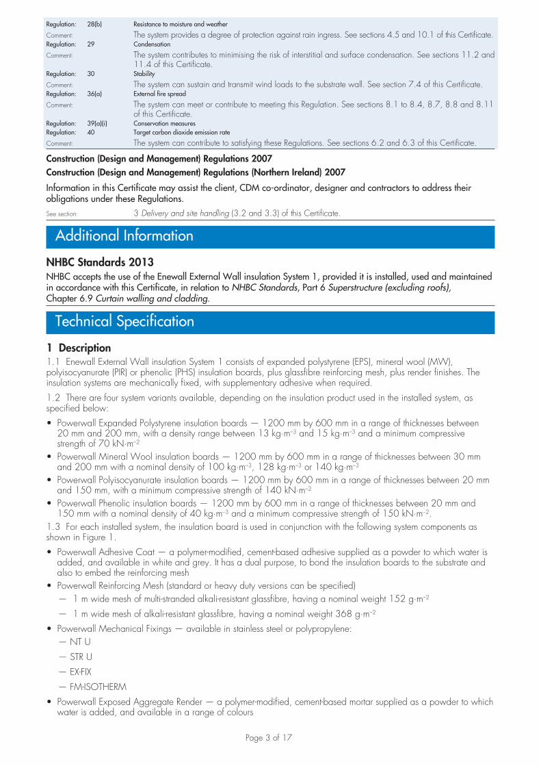
Regulation: 28(b) Resistance to moisture and weather
Comment: The system provides a degree of protection against rain ingress. See sections 4.5 and 10.1 of this Certificate.Regulation: 29 Condensation
Comment: The system contributes to minimising the risk of interstitial and surface condensation. See sections 11.2 and 11.4 of this Certificate.
Regulation: 30 Stability
Comment: The system can sustain and transmit wind loads to the substrate wall. See section 7.4 of this Certificate.Regulation: 36(a) External fire spread
Comment: The system can meet or contribute to meeting this Regulation. See sections 8.1 to 8.4, 8.7, 8.8 and 8.11 of this Certificate.
Regulation: 39(a)(i) Conservation measuresRegulation: 40 Target carbon dioxide emission rate
Comment: The system can contribute to satisfying these Regulations. See sections 6.2 and 6.3 of this Certificate.
Construction (Design and Management) Regulations 2007Construction (Design and Management) Regulations (Northern Ireland) 2007
Information in this Certificate may assist the client, CDM co-ordinator, designer and contractors to address their obligations under these Regulations.See section: 3 Delivery and site handling (3.2 and 3.3) of this Certificate.
Additional Information
NHBC Standards 2013NHBC accepts the use of the Enewall External Wall insulation System 1, provided it is installed, used and maintained in accordance with this Certificate, in relation to NHBC Standards, Part 6 Superstructure (excluding roofs), Chapter 6.9 Curtain walling and cladding.
Technical Specification
1 Description1.1 Enewall External Wall insulation System 1 consists of expanded polystyrene (EPS), mineral wool (MW), polyisocyanurate (PIR) or phenolic (PHS) insulation boards, plus glassfibre reinforcing mesh, plus render finishes. The insulation systems are mechanically fixed, with supplementary adhesive when required.
1.2 There are four system variants available, depending on the insulation product used in the installed system, as specified below:
• Powerwall Expanded Polystyrene insulation boards — 1200 mm by 600 mm in a range of thicknesses between 20 mm and 200 mm, with a density range between 13 kg·m–3 and 15 kg·m–3 and a minimum compressive strength of 70 kN·m–2
• Powerwall Mineral Wool insulation boards — 1200 mm by 600 mm in a range of thicknesses between 30 mm and 200 mm with a nominal density of 100 kg·m–3, 128 kg·m–3 or 140 kg·m–3
• Powerwall Polyisocyanurate insulation boards — 1200 mm by 600 mm in a range of thicknesses between 20 mm and 150 mm, with a minimum compressive strength of 140 kN·m–2
• Powerwall Phenolic insulation boards — 1200 mm by 600 mm in a range of thicknesses between 20 mm and 150 mm with a nominal density of 40 kg·m–3 and a minimum compressive strength of 150 kN·m–2.
1.3 For each installed system, the insulation board is used in conjunction with the following system components as shown in Figure 1.
• Powerwall Adhesive Coat — a polymer-modified, cement-based adhesive supplied as a powder to which water is added, and available in white and grey. It has a dual purpose, to bond the insulation boards to the substrate and also to embed the reinforcing mesh
• Powerwall Reinforcing Mesh (standard or heavy duty versions can be specified) — 1 m wide mesh of multi-stranded alkali-resistant glassfibre, having a nominal weight 152 g·m–2
— 1 m wide mesh of alkali-resistant glassfibre, having a nominal weight 368 g·m–2
• Powerwall Mechanical Fixings — available in stainless steel or polypropylene: — NT U
— STR U
— EX-FIX
— FM-ISOTHERM
• Powerwall Exposed Aggregate Render — a polymer-modified, cement-based mortar supplied as a powder to which water is added, and available in a range of colours

Page 4 of 17
• Powerwall Smooth Band Render — a polymer-modified, cement-based mortar supplied as a powder to which water is added, and available in a range of colours. This render is used on window and door reveals.
• Powerwall Spar-dash Aggregate — available in a range of colours to suit the Powerwall Exposed Aggregate Render.
Ancillary materialsThe following ancillary items are used to aid the installation of the systems, but are outside the scope of this Certificate:
• Powerwall Fungicidal Wash
• a range of standard profiles (beading) for wall base, end stop, corner mesh, expansion joint.
• profile fixings — driven pins with plastic expansion sleeves as approved by the Certificate holder
• silicone sealant.
Figure 1 Enewall External Wall Insulation System 1
smooth-band render
adhesive coat
render finishwith dry-dash
reinforcing mesh
insulation board
wall base profile substrate
1.4 Insulation boards are initially fixed to the external surfaces of walls using the insulation board adhesive (using Powerwall Adhesive Coat powder as described in section 16.6) or one mechanical fixing per board. When the boards have adhered or fixed to the wall, the adhesive coat (Powerwall Adhesive Coat) is trowel-applied to the insulation to a minimum thickness of 3 mm, and the reinforcing mesh is embedded in the adhesive and left to dry. Mechanical fixings are applied through the reinforcing mesh and the insulation boards into the substrate at the frequency of six fixings per square metre as shown in Figure 8.
1.5 The system is finished with an 8 mm to 10 mm thick layer of Powerwall Exposed Aggregate Render and dry-dashed with Powerwall Spar-dash Aggregate (see section 16.20 and 16.21). Thinner insulation boards are secured to the window and door reveals before Powerwall Smooth Band render is applied to the thickness of 8 mm to 10 mm (see Figure 1).
2 Manufacture2.1 As part of the assessment and ongoing surveillance of product quality, the BBA has:
• agreed with the manufacturer the quality control procedures and product testing to be undertaken• assessed and agreed the quality control operated over batches of incoming materials• monitored the production process and verified that it is in accordance with the documented process• evaluated the process for management of nonconformities• checked that equipment has been properly tested and calibrated• undertaken to carry out the above measures on a regular basis through a surveillance process to verify that the
specifications and quality control operated by the manufacturer are being maintained.
2.2 The management system of Enewall Ltd has been assessed and registered as meeting the requirements of BS EN ISO 9001 : 2008 by United Registrar of Systems (URS) (Certificate 1224/A/0001/UK/En).

Page 5 of 17
3 Delivery and site handling3.1 The insulation boards are delivered to site wrapped in polythene. Each pack carries the product identification and batch numbers.
3.2 The renders and spar dash aggregate are delivered to site in 25 kg bags. Each bag carries identification, manufacturer’s batch number and the BBA logo incorporating the number of this Certificate.
3.3 The reinforcing mesh, 1 m wide, is supplied in 50 m rolls.
3.4 The mechanical fixings are boxed separately by the manufacturer.
3.5 The insulation should be stored on a firm, clean, level base, off the ground and under cover until required for use. Care must be taken when handling the insulation to avoid damage.
3.6 The insulation boards should be protected from prolonged exposure to sunlight, either by storing opened packs under cover or re-covering with opaque polythene sheeting. The boards should not be exposed to open flame or other ignition sources.
3.7 Care must be taken when handling the expanded polystyrene insulation boards to avoid contact with solvents or materials containing volatile organic components.
3.8 The spar dash aggregate should be stored off the ground and protected with opaque polythene sheeting. The renders are cementitious materials and should be stored in dry conditions, off the ground, and be protected from frost at all times. Damaged, wet or contaminated products should not be used and must be discarded.
Assessment and Technical Investigations
The following is a summary of the assessment and technical investigations carried out on Enewall External Wall Insulation System 1.
Design Considerations
4 General4.1 The Enewall External Wall Insulation System 1, when installed in accordance with this Certificate, the system is effective in reducing the thermal transmittance (U value) of external masonry walls in new and existing buildings. It is essential that the detailing techniques specified in this Certificate are carried out to a high standard if the ingress of water is to be avoided and the full thermal benefit obtained from the installed system. Only details approved by the Certificate holder must be used.
4.2 The mineral wool system may be used in installations in excess of 18 m in height; the other systems are restricted to a maximum height of 18 m (see section 8).
4.3 The system will improve the weather resistance of a wall and provide a decorative finish. It may only be installed where other potential sources of moisture penetration have been dealt with separately and where there are no signs of dampness on the inner surface of the wall, other than those caused solely by condensation. The system can be used to combat internal condensation.
4.4 Existing buildings, subject to national Building Regulations, should have exterior wall surfaces in accordance with section 14 of this Certificate.
4.5 New buildings subject to national Building Regulations should be constructed in accordance with the relevant recommendations of:
• BS EN 1996-2 : 2006 — the designer should select a construction appropriate to the local wind-driven rain index, paying due regard to the design detailing, workmanship and materials to be used
• BS 8000-3 : 2001.
4.6 Other new buildings, not subject to any if the previous requirements, should also be built in accordance with section 4.5.
4.7 The effect of the installation of the system on the acoustic performance of a construction is outside the scope of this Certificate.
4.8 The fixing of rainwater goods, satellite dishes, clothes lines, hanging baskets and similar items is outside the scope of this Certificate.
4.9 It is essential that the system is installed and maintained in accordance with the conditions set out in this Certificate.
5 Practicability of installationThe system should be installed only by specialised contractors who have successfully undergone training and registration by the Certificate holder.
Note: The BBA operates an UKAS Accredited Approved Installer Scheme for external wall insulation; details of installer companies approved are included on the BBA’s website (www.bbacerts.co.uk).

Page 6 of 17
6 Thermal performance6.1 Calculations of thermal transmittance (U value) should be carried out in accordance with BS EN ISO 6946 : 2007 and BRE Report BR 443 : 2006, using the thermal conductivity of (�90/90 value) as shown in Table 1.
Table 1 Thermal conductivity values
Insulation �90/90 value(W·m–1·K–1)
Expanded polystyreneMineral woolPolyisocyanuratePhenolic (20 mm – 24 mm)Phenolic (25 mm – 44 mm)Phenolic (� 45 mm)
0.0380.0370.0260.0230.0210.020
6.2 The U value of a wall will depend on the selected insulation type and thickness, the number and type of fixings and the insulating value of the substrate masonry and its internal finish. Figures for typical design U values, calculated in accordance with section 6.1, are given in Table 2.
Table 2 Insulation thickness required to achieve design U values given in national Building Regulations
U value(1)
(W·m–2·K–1)Insulation type Insulation thickness(2)
(mm)
0.19
EPSMineral wool
PIRPhenolic
200200150130
0.26
EPSMineral wool
PIRPhenolic
150150110100
0.28
EPSMineral wool
PIRPhenolic
140140100 90
0.30
EPSMineral wool
PIRPhenolic
130130 90 80
(1) Values derived using 200 mm dense concrete block with thermal conductivity of 1.75 W·m–1·K–1 and six stainless steel fixings per m2 with 8 mm diameter.
(2) Based upon incremental insulation thicknesses of 10 mm.
6.3 The system can maintain, or contribute to maintaining, continuity of thermal insulation around openings and at junctions between external walls and other building elements. Details shown in Figures 9 and 10 will allow use of the default psi values for Accredited Construction details in Emission Rate calculations to SAP 2009 or the Simplified Building Energy Model (SBEM). Guidance on limiting heat loss at junctions can be found in:
England and Wales — Approved Documents to Part L and, for new thermal elements to existing buildings, Accredited Construction Details (version 1.0) (for new-build, see also SAP 2009, Appendix K, and the iSBEM User Manual)Scotland — Accredited Construction Details (Scotland)Northern Ireland — Accredited Construction Details (version 1.0).
7 Strength and stability7.1 When installed on masonry or concrete walls, the system can adequately transfer to the wall the self-weight and negative and positive (suction and pressure) wind loads normally experienced in the United Kingdom.
7.2 Positive wind load (pressure) is transferred to the substrate wall directly via bearing and compression of the render, adhesive and insulation.
7.3 Negative wind pressure (suction) is resisted by the bond between each component. The insulation boards are retained by the external wall insulation system anchors and reinforcement mesh. The mechanical fixings must always be fixed through the reinforcement mesh.
7.4 The wind loads on the wall should be calculated in accordance with BS EN 1991-1-4 : 2005. Special consideration should be given to locations with high wind-load pressure coefficients as additional fixings may be necessary. In accordance with BS EN 1990 : 2002, it is recommended that a load factor of 1.5 is used to
determine the ultimate wind load to be resisted by the system.

Page 7 of 17
7.5 Assessment of structural performance for individual buildings must be carried out by a suitably qualified and experienced individual to confirm that:
• the substrate wall has adequate strength to resist additional loads that may be applied as a result of installing the system, ignoring any positive contribution that may occur from the insulation system
• the proposed system and associated fixing pattern (see Figure 8) provides adequate resistance to negative wind loads [based on the results of the site investigation and test results given in Table 3 (see section 7.7)]
• an appropriate number of site-specific pull-out tests must be conducted on the substrate of the building to determine the minimum resistance to failure of the fixings. The characteristic pull-out resistance should be determined in accordance with the guidance given in ETAG 014 : 2002, Annex D (ie by calculating the mean of the lowest five values and multiplying by 0.6).
7.6 The number of fixings and the span between fixings should be determined by the system designer. Provided the substrate wall is suitable and an appropriate fixing is used, the mechanical fixings will transfer the weight of the system to the substrate wall. The fixing must be selected to give adequate support to the weight of the system at the minimum spacing given in this Certificate.
7.7 Typical characteristic pull-out strengths for the fixings taken from the corresponding European Technical Approval (ETA) are given in Table 3; however, these values are dependent on the substrate and the fixing must be selected to suit the loads and substrate concerned.
Table 3 Fixings — typical characteristic pull-out strengths
Fixing type Substrate ETA Number Drill diameter(mm)
Embedment depth(mm)
Typical pull-out strength(1)
(kN)
NT U Concrete/solid brick ETA-05/0009 8 35 1.2 (concrete)1.5 (brick)
STR U Concrete/solid brick ETA-04/0023 8 50 1.5 (concrete)1.5 (brick)
EX-FIX Concrete/solid brick Test Report R4239 10 50 0.8 (concrete)0.75 (brick)
FM-ISOTHERM Concrete ETA-11/0254 8 �60 0.6 (concrete)
(1) Values are determined in accordance with ETAG 014 : 2002 and are dependent on the substrate. Pull-out strength figures are for concrete, and/or solid brick.
7.8 The design pull-out resistance is the average pull-out resistance multiplied by the number of fixings per board divided by a safety factor of 2 or by a method agreed by a suitably qualified and experienced individual.
Impact resistance7.9 Hard body impact tests(1) were carried out and the system is suitable for use in category I to category III(2).(1) These tests were conducted in accordance to MOAT No 22 : 1988.
(2) These categories are defined in ETAG 004 : 2011 as:
• Category I – a zone readily accessible at ground level to the public and vulnerable to hard body impacts but not subjected to abnormally rough use
• Category II – a zone liable to impacts from thrown or kicked objects, but in public locations where the height of the system will limit the size of the impact; or at lower levels where access to the building is primarily to those with some incentive to exercise care
• Category III – a zone not likely to be damaged by normal impacts caused by people or by thrown or kicked objects.
8 Behaviour in relation to fireGeneral
8.1 The system has a surface spread of flame Class B-s1, d0 classification in accordance with BS EN 13501-1 : 2007.
8.2 The fire classification apply to the full range of insulation thicknesses covered by the Certificate (see section 1.2).
8.3 This classification applies to the range colours available on Powerwall Exposed Aggregate and Powerwall Smooth Band renders, and Powerwall Spar-dash Aggregate.
8.4 The MW insulation, reinforcing coat with glassfibre mesh and Powerwall Exposed Aggregate and Powerwall Smooth Band renders are classified as non-combustible. The fire classification also applies to both the standard and heavy duty glassfibre mesh covered by the Certificate (see section 1.2).
8.5 In multi-storey applications, a minimum of one 8 mm diameter stainless steel anchor per square metre is required. The anchor is applied to prevent the system from collapsing, in case the insulation is lost due to fire and must be designed to resist the bending and shear stresses resulting from the dead load from the render.

Page 8 of 17
8.6 Requirements under the various national Building Regulations are:England, Wales and Northern Ireland
8.7 The system incorporating mineral wool insulation, is suitable for use on or at any distance from the boundary and can be used without height restriction.
8.8 The system incorporating the EPS, PIR or PHS insulation is suitable for use on or at any distance from the boundary and in buildings up to 18 m in height.
Scotland
8.9 The system incorporating mineral wool insulation using non-combustible fixings, is suitable for use on or at any distance from the boundary and can be used without height restriction.
8.10 The system incorporating the EPS, PIR or PHS insulation is classified as ‘low risk’ combustible materials. These systems are suitable for use in buildings up to 18 m in height and must not be used within 1 m of the boundary.
8.11 Application to second storey walls and above should include at least one non-combustible fixing per square metre and fire breaks in line with compartment walls and floors. In Scotland, the systems must be included in calculations of unprotected areas (see Figure 2).
8.12 Designers must ensure that the completed wall provides any required period of fire resistance and refer to the documents supporting the national Building Regulations for detailed guidance.
Figure 2 Fire barrier
9 Proximity of flues and appliancesWhen the system is installed in close proximity to certain flue pipes, the relevant provisions of the national Building Regulations should be met:
England and Wales — Approved Document J
Scotland — Mandatory Standard 3.19, clause 3.19.4(1)(2)
(1) Technical Handbook (Domestic).
(2) Technical Handbook (Non-Domestic).
Northern Ireland — Technical Booklet L.
10 Rain penetration10.1 The system will provide a degree of protection against rain ingress. However, care should be taken to ensure that walls are adequately weather tight prior to the application of the insulation system. The insulation system may only be installed where there are no signs of dampness on the inner surface of the substrate other
than those caused solely by condensation.
10.2 Designers and installers should take particular care in detailing around openings, penetrations and movement joints to minimise the risk of rain ingress; only details approved by the Certificate holder should be used.
10.3 Guidance given in BRE Report BR 262 : 2002 should be followed in connection with the weathertightness of solid wall constructions. The designer should select a construction appropriate to the local wind-driven rain index, paying due regard to the design detailing, workmanship and materials to be used.

Page 9 of 17
10.4 At the tops of walls, the system should be protected by an adequate overhang or other detail designed for use with this type of system (see section 16.23).
11 Risk of condensation11.1 Designers must ensure that an appropriate condensation risk analysis has been carried out for all parts of construction, including openings and penetrations at junctions between the insulation system, to minimise the risk of condensation. The recommendations of the BS 5250 : 2011 should be followed.
Surface condensation11.2 Walls will adequately limit the risk of surface condensation when the thermal transmittance (U value) does not exceed 0.7 W·m–2·K–1 at any point and the junctions with other elements and openings comply with section 6.3.
11.3 Walls will adequately limit the risk of surface condensation when the thermal transmittance (U value) does not exceed 1.2 W·m–1·K–1 at any point. Guidance may be obtained from BS 5250 : 2011 (Section 4, Annex D) and BRE Report (BR 262 : 2002).
Interstitial condensation11.4 Walls incorporating the systems will adequately limit the risk of interstitial condensation when they are designed and constructed in accordance with this Certificate.
11.5 Powerwall Exposed Aggregate Render has an equivalent air layer thickness (Sd) of approximately 0.16 m. This corresponds to a water vapour resistance factor (µ) of approximately 20 for a render thickness of 8 mm.
11.6 The water vapour resistance factor (µ) (for the insulation boards, as taken from BS EN ISO 10456 : 2007, Table 4) is:• adhesive 20• expanded polystyrene 60• mineral wool 1• Polyisocyanurate 60• phenolic foam 50• Exposed Aggregate/Smooth Band renders 20.
12 Maintenance and repair12.1 Regular checks should be made on the installed system, including:
• visual inspection of the render for signs of damage. Cracks in the render exceeding 0.2 mm must be repaired• examination of the sealant around openings and service entry points
• visual inspection of architectural details designed to shed water to confirm that they are performing properly• visual inspection to ensure that water is not leaking from external downpipes or gutters; such leakage could
penetrate the rendering• necessary repairs should be effected immediately and the sealant joints at window and door frames replaced at
regular intervals• maintenance schedules should include the replacement and resealing of joints, for example between the insulation
systems and window and door frame.
12.2 For a 60 year durability, a detailed maintenance plan must be prepared and provided to the building manager/owner on completion. As a minimum, this should include an inspection for evidence of defects 12 months after the application and subsequently every five years.
12.3 Damaged areas must be repaired using the appropriate components and procedures detailed in the Certificate holder’s installation instructions and in accordance with BS EN 13914-1 : 2005.
13 Durability13.1 The system will have a service life of not less than 30 years, provided any damage to the surface finish is repaired immediately, and regular maintenance is undertaken including checks on joints in the system and on external plumbing fitments to identify leakage of rainwater into the system, enabling steps to be taken to correct
the defects (see section 12). In order to achieve this, depending on the building’s location, degree of exposure and detailing, it may be necessary to repair or replace isolated areas.
13.2 The system’s service life can extend to 60 years provided a planned inspection and maintenance programme is introduced in accordance with Section 12. An extended 60 years’ service life requires the use of stainless steel beads, stainless steel fixings [304 Grade (1.4301)], plastic anchor material such as polyamide (PA6 and PA6.6), polyethylene (PE) or polypropylene (PP) and the following of an appropriate repair and maintenance schedule as covered by the Certificate holder’s Repair and Maintenance Manual. Any damage to the surface finish should be repaired within a time period agreed by the Certificate holder.

Page 10 of 17
13.3 Any render containing Portland cement may be subject to lime bloom. The occurrence of this may be reduced by avoiding application in adverse weather conditions. The effect is transient and is less noticeable on lighter colours.
13.4 The render may become discoloured with time, the rate depending on the initial colour, the degree of exposure and atmospheric pollution, as well as the design and detailing of the wall. In common with traditional renders, discoloration by algae and lichens may occur in wet areas. The appearance may be restored by a suitable power wash or, if required, by over coating.
13.5 To maintain a high quality aesthetic appearance, it may be necessary to periodically overcoat the building using a suitable masonry coating (ie one covered by a valid BBA Certificate for this purpose). Care should be taken not to adversely affect the water vapour transmission or fire characteristics of the system. The advice of the Certificate holder should be sought as to the suitability of a particular product.
Installation
14 Site survey and preliminary work14.1 A pre-installation survey of the property is carried out to determine suitability for treatment and the need for any necessary repairs to the building structure before application of the Enewall External Wall Insulation System 1. A specification is prepared for each elevation of the building indicating:
• the position of beads• detailing around windows, doors and at eaves• damp-proof course (dpc) level• exact position of expansion joints• where required, additional corner mesh and reinforcement• areas where flexible sealants must be used• any alterations to external plumbing• where required, the position of fire barriers.
14.2 The survey should include tests conducted on the walls of the building by the Certificate holder or their approved installers (see section 15) to determine the pull-out resistance of the proposed mechanical fixings for the specific substrate. An assessment and recommendation is made on the type and number of fixings required to withstand the building’s expected wind loading, based on calculations using the fixing’s pull-out resistance test data (see section 7).
14.3 External plumbing should be removed before installation and alterations made to underground drainage, where appropriate, to accommodate repositioning of the plumbing on the finished face of the systems.
14.4 Surfaces should be sound, clean and free from loose material. The flatness of surfaces must be checked; this may be achieved using a straight edge spanning the storey height. Any excessive irregularities, ie greater than 10 mm in one metre, must be made good prior to installation to ensure that the insulation boards are installed with a smooth, in-plane finished surface.
14.5 New buildings should be of sound masonry, dense or no-fines concrete construction.
14.6 On existing buildings, purpose-made window sills must be fitted to extend beyond the finished face of the system. New buildings should incorporate suitably deep sills.
14.7 Where surfaces are covered with an existing rendering, it is essential that the bond between the background and the render is adequate. All loose areas should be hacked off and reinstated.
14.8 Internal wet work, eg screed or plastering, should be completed and allowed to dry prior to the application of a system.
14.9 All modifications, such as provision for cavity barriers and fire stopping (see section 8) and necessary repairs to the building structure must be completed before installation commences.
15 Approved installersApplication of the system, within the context of this Certificate, is carried out by approved installers recommended or recognised by the Certificate holder. Such an installer is a company:• employing operatives who have been trained and approved by the Certificate holder to install the system • which has undertaken to comply with the Certificate holder’s application procedures, containing the requirement for
each application team to include at least one operative trained by the Certificate holder• subject to at least one inspection per annum by the Certificate holder to ensure that suitable site practices are being
employed. This may include unannounced site inspections.
16 ProcedureGeneral16.1 Installation of the system should be carried out in accordance with the Certificate holder’s current installation instructions.

Page 11 of 17
16.2 One coat of Powerwall Fungicidal Wash is applied by brush, roller or spray to the entire surface of the wall.
16.3 Weather conditions should be monitored to ensure suitable application and curing conditions. The insulation board adhesive and rendering must not be applied when exposure to frost is likely, in damp/wet conditions, at temperatures below 5°C or above 30°C, or where these temperatures are likely to be exceeded during the curing period. The render must be protected from rapid drying and should not be applied on elevations in direct sunlight.
16.4 All rendering should be in accordance with the relevant recommendations of BS EN 13914-1 : 2005.
Positioning and securing insulation boards16.5 The Powerwall base profile is secured to the external wall above the dpc, using profile fixings at approximately 400 mm centres (see Figure 3).
Figure 3 Typical section at base level
16.6 The insulation board adhesive is prepared using Powerwall Adhesive Coat powder, which is mixed for at least five minutes with water, using an electric paddle mixer. One litre of water is used with 4.5 kg of powder. The adhesive is applied in dabs and should cover at least 30 per cent of the board. Four dabs are applied on each corner and one dab in the centre of each board (see Figure 4).
Figure 4 Insulation boards adhesive pattern
insulation board
adhesive dabs
16.7 The first run of insulation boards are positioned on the base profile, and pressed firmly against the wall. Subsequent rows of boards are positioned so that the vertical board joints are staggered and overlapped at the building corners (see Figure 5). If required, the boards may be arranged with the longer edge positioned vertically. On flat surfaces the boards can first be fixed using mechanical fixings at the centre of each board during the installation process, instead of using the adhesive.

Page 12 of 17
Figure 5 Insulation boards — corner detail
16.8 For both, dry and wet-fix systems (ie with or without adhesive applied) the insulation boards are mechanically fastened to the substrate using the mechanical fixing pattern illustrated in Figure 8. The fixing pattern shown would equate to six fixings per square metre.
16.9 Care must be taken to ensure that all board edges are butted tightly together, and alignment should be checked as work proceeds. For the expanded polystyrene, any high spots or irregularities should be removed by lightly planing with a rasp. The window and door reveals should always be insulated. However, where clearance is limited, the thinner available size insulation boards should be used.
16.10 To fit around details such as doors and windows, insulation boards may be cut with a sharp knife or a fine-tooth saw. Where required, purpose-made window sills are fitted. They are designed to prevent water ingress and incorporate drips to shed water clear of the system.
16.11 Installation continues until the whole wall is completely covered and built up to the building soffits in an existing building (see Figure 9).
Movement joints16.12 Movement joints in the substrate must be continued through the system. These are normally at centres of approximately 7 m along a building but exact positioning will be dependent on the individual requirements of each job. The joint detail using purpose-made metal trims is illustrated in Figure 6.
Figure 6 Movement joint
Reinforcing and mechanical fixing16.13 The adhesive coat is trowel-applied to the surface of dry insulation boards to a minimum thickness of 3 mm. The adhesive coat is prepared by mixing one litre of water with 6.4 kg of powder, using an electrically driven paddle mixer or a concrete mixer for at least five minutes.

Page 13 of 17
16.14 An alkali-resisting glassfibre mesh (either standard or heavy duty) is embedded into the adhesive with 100 mm overlap at joints. Extra mesh is used around openings as illustrated in Figure 7.
Figure 7 Insulation boards — reinforcement details
typical aperture
stress reinforcement patches400 200 mm
insulation cut to L-shapeat corner of apertures
insulation boardsfixed broken bondat corners
minimum cuttingsize 250 mmvertical/horizontal
minimum vertical jointoffset 250 mmbase profile
250
16.15 After the adhesive coat has been left to dry for at least 24 hours, holes are drilled typically at 500 mm horizontal centres and 300 mm vertical centres (the vertical drill pattern is changed to 400 mm vertical centres at regular intervals) as illustrated in Figure 8. Mechanical fixings are inserted through the reinforcing mesh and insulation boards and tapped firmly into the substrate wall. The fixing pattern shown in Figure 8 would equate to six fixings per square metre. Variation to the fixing pattern may be necessary; however, the system designer needs to take into consideration that the increase in number of fixings will have an impact on the U value of the installed system (see section 6.2).
Figure 8 Fixing pattern
16.16 Mechanical fixings are positioned 300 mm apart around window details and 200 mm vertical centres at building corners.
16.17 Corner beads are fixed to the building corners, door and window heads and jambs, and are formed using adhesive coat in accordance with the Certificate holder’s instructions (see Figure 10). The adhesive coat must be left to harden for at least one day before application of the render coat.
16.18 Stop beads are positioned vertically, eg at separating wall positions where the adjoining house does not require treatment.

Page 14 of 17
Rendering and finishing16.19 Prior to the application of the render coat (Powerwall Exposed Aggregate), a bead of silicone sealant is gun-applied at window and door frames, overhanging eaves, gas and electric meter boxes, wall vents, or where the render abuts any other building material or surface.
16.20 Powerwall Exposed Aggregate render is prepared for use by mixing one litre of water with 4.5 kg of powder for at least five minutes, using an electric paddle mixer or a concrete mixer.
16.21 One coat of the render is trowel-applied to a minimum thickness of 8 mm. While the render is still soft, Powerwall Spar-dash Aggregate is thrown onto the surface. On completion, the surface must be checked to ensure an even coverage of spar-dash has been achieved. Where necessary, the aggregate should be lightly tapped to ensure that a good bond is achieved.
16.22 The smooth band render is prepared for use by mixing one litre of water with 4.5 kg of powder for at least five minutes, using an electric paddle mixer. Powerwall Smooth Band render is trowel-applied to a minimum thickness of 8 mm to the insulated door and window reveals.
16.23 At the tops of walls the system must be protected by an adequate overhang or by an adequately sealed purpose-made flashing (see Figure 9).
Figure 9 Eaves detail
16.24 Care must be taken in the detailing of the system around openings and projections (see Figures 10 and 11). To achieve a 60 year service life, the system is finished against a stainless steel stop bead at reveals, to allow for replacement of windows.

Page 15 of 17
Figure 10 Insulated window and door reveal
insulation board
render finish
reinforcing mesh embedded in adhesive
profile fixings
mechanical fixing
corner profile
silicone seal
Figure 11 Oversill detail
silicone seal
oversill bedded on continuousbeads of silicone sealant
existing sill
new oversill
silicone seal
insulation board
mechanical insulation fixingminimum embedment depth 50 mm
reinforced mesh embedded in adhesive
external render finish
existing substrate
16.25 To prevent the renders from drying too rapidly, they should not be applied in direct sunlight. Continuous surfaces must be completed without a break.
16.26 On completion of the installation, external fittings, eg rainwater goods, are re-fixed through the system into the substrate.
Repair16.27 Damaged areas must be repaired using the appropriate components and procedures detailed in the Certificate holder’s installation instructions in accordance with BS EN 13914-1 : 2005.

Page 16 of 17
Technical Investigations
17 Tests17.1 Tests were carried out on the system in accordance with MOAT No 22 : 1988 and ETAG 004 : 2011 to determine:• component characterisation• density of insulation board• heat/spray cycling• resistance to freeze/thaw• water absorption of render• water vapour permeability• impact resistance.
17.2 An examination was made of data relating to:• surface spread of flame tests• pull-out strength of fixings• durability of finish• thermal conductivity.
18 Investigations18.1 The manufacturing process, the methods adopted for quality control of manufactured and bought-in components, and details of the quality and composition of the materials used, were examined.
18.2 A condensation risk analysis was undertaken.
18.3 A series of U value calculations were carried out.
18.4 A calculation was undertaken to confirm the thermal conductivity (�90/90 value).
18.5 An assessment was made of the practicability of installation and the effectiveness of detailing techniques.
BibliographyBS 5250 : 2011 Code of practice for control of condensation in buildings BS 8000-3 : 2001 Workmanship on building sites — Code of practice for masonry BS EN 1990 : 2002 Eurocode — Basis of structural design BS EN 1991-1-4 : 2005 Eurocode 1. Actions on structures — General actions — Wind actions BS EN 1996-2 : 2006 Eurocode 6 – Design of masonry structures — Design considerations, selection of materials and execution of masonryBS EN 13501-1 : 2007 Fire classification of construction products and building elements — Classification using test data from reaction to fire testsBS EN 13914-1 : 2005 Design, preparation and application of external rendering and internal plastering — External rendering BS EN ISO 6946 : 2007 Building components and building elements — Thermal resistance and thermal transmittance — Calculation method BS EN ISO 9001 : 2008 Quality management systems — Requirements BS EN ISO 10456 : 2007 Building materials and products — Hygrothermal properties. Tabulated design values and procedures for determining declared and design thermal values ETAG 004 : 2011 Guideline for European Technical Approval of External Thermal Insulation Composite Systems with RenderingETAG 014 : 2002 Guideline for European Technical Approval of Plastic Anchors for fixing of External Thermal Insulation Composite Systems with RenderingMOAT No 22 : 1988 UEAtc Directives for the Assessment of External Insulation Systems for Walls (Expanded Polystyrene Insulation Faced with a Thin Rendering)BRE Report (BR 443 : 2006) Conventions for U-value calculationsBRE Report (BR 262 : 2002 ) Thermal insulation: avoiding risks

Page 17 of 17
Conditions of Certification
19 Conditions19.1 This Certificate:• relates only to the product/system that is named and described on the front page• is issued only to the company, firm, organisation or person named on the front page — no other company, firm,
organisation or person may hold or claim that this Certificate has been issued to them• is valid only within the UK• has to be read, considered and used as a whole document — it may be misleading and will be incomplete to be
selective• is copyright of the BBA• is subject to English Law.
19.2 Publications, documents, specifications, legislation, regulations, standards and the like referenced in this Certificate are those that were current and/or deemed relevant by the BBA at the date of issue or reissue of this Certificate.
19.3 This Certificate will remain valid for an unlimited period provided that the product/system and its manufacture and/or fabrication, including all related and relevant parts and processes thereof:• are maintained at or above the levels which have been assessed and found to be satisfactory by the BBA• continue to be checked as and when deemed appropriate by the BBA under arrangements that it will determine• are reviewed by the BBA as and when it considers appropriate.
19.4 The BBA has used due skill, care and diligence in preparing this Certificate, but no warranty is provided.
19.5 In issuing this Certificate, the BBA is not responsible and is excluded from any liability to any company, firm, organisation or person, for any matters arising directly or indirectly from:• the presence or absence of any patent, intellectual property or similar rights subsisting in the product/system or any
other product/system• the right of the Certificate holder to manufacture, supply, install, maintain or market the product/system• actual installations of the product/system, including their nature, design, methods, performance, workmanship and
maintenance• any works and constructions in which the product/system is installed, including their nature, design, methods,
performance, workmanship and maintenance• any loss or damage, including personal injury, howsoever caused by the product/system, including its manufacture,
supply, installation, use, maintenance and removal• any claims by the manufacturer relating to CE marking.
19.6 Any information relating to the manufacture, supply, installation, use, maintenance and removal of this product/system which is contained or referred to in this Certificate is the minimum required to be met when the product/system is manufactured, supplied, installed, used, maintained and removed. It does not purport in any way to restate the requirements of the Health and Safety at Work etc. Act 1974, or of any other statutory, common law or other duty which may exist at the date of issue or reissue of this Certificate; nor is conformity with such information to be taken as satisfying the requirements of the 1974 Act or of any statutory, common law or other duty of care.
British Board of Agrément tel: 01923 665300Bucknalls Lane fax: 01923 665301Watford e-mail: [email protected] WD25 9BA website: www.bbacerts.co.uk©2013