bay area air quality management district dr af t/media/files/engineering/permit... ·...
TRANSCRIPT

BAY AREA AIR QUALITY MANAGEMENT DISTRICT
Engineering Division
Permit Handbook
DRAFT

E N G I N E E R I N G D I V I S I O N
Permit Handbook
Organized by
M.K. Carol Lee
Content Prepared by
M.K. Carol Lee
Bay Area Air Quality Management District
375 Beale Street, Suite 600
San Francisco, CA 94105
Phone (415) 749-5000 • Fax (415) 749-5030

II
BAY AREA AIR QUALITY MANAGEMENT DISTRICT
PERMIT HANDBOOK
Table of Contents
INTRODUCTION .................................................................................................. 5
GENERAL APPLICATION GUIDANCE ............................................................... 6
AIR QUALITY PERMIT REQUIREMENTS ........................................................................................... 6 COMPLETENESS DETERMINATION .................................................................................................. 6
GENERAL EVALUATION GUIDANCE ................................................................ 9
COMPLETENESS DETERMINATION .................................................................................................. 9 EVALUATION REPORT .................................................................................................................. 9 BACKGROUND ............................................................................................................................. 9 EMISSION CALCULATIONS ............................................................................................................ 9 APPLICABLE REQUIREMENTS ...................................................................................................... 10 PERMIT CONDITIONS .................................................................................................................. 16
PERMIT CONDITION GUIDANCE ..................................................................... 17
BACKGROUND ........................................................................................................................... 17 CONDITION BASIS CODES ........................................................................................................... 17 TEMPLATE PERMIT CONDITIONS ................................................................................................. 17
Permit Conditions for Boilers, Steam Generators & Process Heaters, fired with fuel oil only: ...................... 20 Permit Conditions for Boilers, Steam Generators & Process Heaters, fired with natural gas and fuel oil as
backup fuel: ..................................................................................................................................................... 21 Permit Conditions for Boilers, Steam Generators & Process Heaters, fired with natural gas only: ................ 22 Permit Conditions for Boilers, Steam Generators & Process Heaters, fired with other gaseous fuel: ............. 23 Permit Conditions for Emergency Stationary Diesel Engines: ........................................................................ 24 Permit Conditions for Emergency Stationary Natural Gas Engines: ............................................................... 25 Permit Conditions for Portable Diesel Engine: ............................................................................................... 26 Permit Conditions for Bulk Loading: .............................................................................................................. 28 Permit Conditions for Marine Loading/Offloading Facility: ........................................................................... 29 Permit Conditions for Oil-Water Separator: .................................................................................................... 30 Permit Conditions for Petroleum Refinery Fugitive Emissions: ..................................................................... 31 Permit Conditions for Natural Gas Production Facilities and Crude Oil Production Facilities: ...................... 32 Permit Conditions for Storage Tanks (general conditions): ............................................................................ 37 Permit Conditions for Storage Tanks (additional conditions for internal or external floating roofs): ............. 38 Permit Conditions for Vapor Recovery Systems: ............................................................................................ 39 Permit Conditions for Coating Operations (including Graphic Arts): ............................................................. 40 Permit Conditions for Mixing Vats for Coating, Adhesives, and Ink Manufacturing: .................................... 41 Permit Conditions for Screening Mill for Coating, Adhesives, and Ink Manufacturing: ................................ 42 Permit Conditions for Solvent Cleaning Operations: ...................................................................................... 43 Permit Conditions for Wave Solder Flux Applicator: ..................................................................................... 44 Permit Conditions for Flexible and Rigid Disc Manufacturing: ...................................................................... 45 Permit Conditions for Semiconductor Manufacturing Operations: ................................................................. 46 Permit Conditions for Anaerobic Digester: ..................................................................................................... 47 Permit Conditions for Wastewater Treatment Facilities: ................................................................................ 48 Permit Conditions for End of Remediation Project (for Airstripping or Soil Vapor Extraction): ................... 49 Permit Conditions for Combined Airstripping and Soil Vapor Extraction Operation Using Thermal or
Catalytic Oxidizer or Activated Carbon Vessels: ............................................................................................ 50 Permit Conditions for Portable Airstripping or Soil Vapor Extraction Operation Using Thermal Oxidizer: .. 53 Permit Conditions for Decorative Chrome Plating (or operations using less than 500,000 amp-hr/yr): ......... 55 Permit Conditions for Hard Chrome Plating: .................................................................................................. 57 Permit Conditions for Trivalent Chrome Plating: ........................................................................................... 60 Permit Conditions for Sterilizer w/Catalytic Oxidation: ................................................................................. 61

III
Permit Conditions for Non-Halogenated Solvent Dry Cleaning: .................................................................... 62 Permit Conditions for Perchloroethylene Dry Cleaning: ................................................................................. 63 Permit Conditions for Abrasive Blasting (BACT with abatement): ................................................................ 68 Permit Conditions for Abrasive Blasting (non-BACT with abatement): ......................................................... 69 Permit Conditions for Abrasive Blasting (non-BACT with no abatement): .................................................... 70 Permit Conditions for Asphalt Drum Mixer: ................................................................................................... 71 Permit Conditions for Coffee Roasting Operations: ........................................................................................ 72 Permit Conditions for Cooling Towers: .......................................................................................................... 74 Permit Conditions for Concrete Batch Plants: ................................................................................................. 75 Permit Conditions for Animal Crematories: .................................................................................................... 76 Permit Conditions for Human Crematories: .................................................................................................... 78 Permit Conditions for Crushing and Grinding Operations: ............................................................................. 80 Permit Conditions for Miscellaneous Organic Operations: ............................................................................. 81 Permit Conditions for Portable Equipment (to be included with source specific conditions): ........................ 82 Permit Conditions for Polyester Resin Manufacturing: ................................................................................... 83 Permit Conditions for Gel Coat and Resin Application: ................................................................................. 84 Permit Conditions for Tub Grinder (powered by electricity & stationary): ..................................................... 85 Permit Conditions for Tub Grinder w/Diesel Engine (Stationary): ................................................................. 86 Permit Conditions for Portable Tub Grinder w/Portable Diesel Engine: ......................................................... 87 Permit Conditions for Baghouse: .................................................................................................................... 89 Permit Conditions for Carbon Abatement: ...................................................................................................... 90 Permit Conditions for RACT for IC Engines (> 250 HP): .............................................................................. 91 Permit Conditions for Source Testing: ............................................................................................................ 92 Permit Conditions for “Allowable Temperature Excursions” of Thermal Oxidizers: ..................................... 93 Permit Conditions for Thermal Oxidizers: ...................................................................................................... 94 Permit Conditions for RACT for Thermal Oxidizers (> 7.5 MMBTU/hr): ..................................................... 95 Permit Conditions for Water Spray System with throughput limit: ................................................................. 96
SOURCE-SPECIFIC GUIDANCE ....................................................................... 97
1. GENERAL INSTRUCTIONS TO USING THESE GUIDELINES .......................................................... 99 2.1 BOILERS, STEAM GENERATORS & PROCESS HEATERS............................................................. 100 2.3.1 STATIONARY DIESEL ENGINES .................................................................................................... 103 2.3.2 STATIONARY NATURAL GAS ENGINES ...................................................................................... 107 2.3.3 PORTABLE DIESEL ENGINES......................................................................................................... 109 2.4.1 MICRO TURBINES (25-500 KW) ...................................................................................................... 113 3.1 BULK LOADING FACILITIES ............................................................................................................. 116 3.2 GASOLINE DISPENSING FACILITIES ............................................................................................... 119 3.3 OIL-WATER SEPARATORS ................................................................................................................ 121 3.4 PETROLEUM REFINERY FUGITIVE EMISSIONS ........................................................................... 123 3.5 NATURAL GAS FACILITIES AND CRUDE OIL FACILITIES ......................................................... 126 4.0 ORGANIC LIQUID STORAGE TANK ................................................................................................. 132 5.1 SPRAY BOOTHS & SPRAY GUNS ..................................................................................................... 134 5.2 COATING, ADHESIVES, AND INK MANUFACTURING ................................................................ 138 5.3 GRAPHIC ARTS PRINTING AND COATING OPERATIONS ........................................................... 141 6.1 COLD SOLVENT CLEANING ............................................................................................................. 143 6.2 VAPOR SOLVENT & CONVEYORIZED SOLVENT CLEANING .................................................... 145 6.3 WIPE CLEANING OPERATION .......................................................................................................... 148 7.2 ELECTRONIC ASSEMBLY AND WAVE SOLDERING OPERATONS ............................................ 150 7.3 FLEXIBLE AND RIGID DISC MANUFACTURING .......................................................................... 153 7.4 SEMICONDUCTOR FABRICATION ................................................................................................... 155 8.2 WASTEWATER TREATMENT FACILITIES ...................................................................................... 157 9.1 AIRSTRIPPING ...................................................................................................................................... 162 9.2 SOIL VAPOR EXTRACTION ............................................................................................................... 166 10.1 CHROME PLATING (HEXAVALENT) ............................................................................................. 170 10.2 ETHYLENE OXIDE STERILIZERS ................................................................................................... 173 10.4 NON-HALOGENATED SOLVENT DRYCLEANING ...................................................................... 176 10.5 SYNTHETIC SOLVENT DRYCLEANING ........................................................................................ 178 11.1 ABRASIVE BLASTING OPERATIONS............................................................................................. 180 11.2 ASPHALT (HOT MIX) FACILITIES .................................................................................................. 183 11.3 COFFEE ROASTING OPERATIONS ................................................................................................. 196 11.4 COOLING TOWERS ........................................................................................................................... 199
IV
11.5 CONCRETE BATCH PLANTS ........................................................................................................... 204 11.6 CREMATORIES................................................................................................................................... 211 11.7 CRUSHING AND GRINDING ............................................................................................................ 215 11.9 MISCELLANEOUS ORGANIC OPERATIONS ................................................................................. 219 11.10 PORTABLE EQUIPMENT ............................................................................................................... 222 11.11 POLYESTER RESIN MANUFACTURING ...................................................................................... 223 11.12 POLYESTER RESIN OPERATIONS ................................................................................................ 225 11.13 TUB GRINDERS ................................................................................................................................ 236
LIST OF APPENDICES .................................................................................... 237
A. PERMIT EXEMPTION GUIDANCE .................................................................................. 238 B. DATA FORM GUIDANCE ................................................................................................ 265 C. FEE CALCULATION GUIDANCE .................................................................................... 292 D. COMPLETENESS DETERMINATION CHECKLIST ......................................................... 299 E. EVALUATION REPORT TEMPLATE GUIDANCE ............................................................ 301 F. FREQUENTLY ASKED QUESTIONS – PERMITTING & OTHER ............................................ 308

V
INTRODUCTION by M.K. Carol Lee
July 18, 2006
The BAAQMD Permit Handbook is intended to be used by permit applicants, District permit engineers,
District inspectors, and other District staff.
The purpose of this Permit Handbook is to set forth the fixed standards and objective measurements to be
used by District engineers in determining whether a particular permit may be issued to a particular project
belonging to a given source category.
Permits prepared in accordance with the Permit Handbook are deemed “ministerial” for the purposes of the
California Environmental Quality Act (CEQA). Permits that deviate from or sources not covered by the
Permit Handbook will be reviewed on a case-by-case basis for compliance with CEQA. All of these steps
will be taken in conformance with the District’s permitting regulations.
The Permit Handbook also contains a set of standardized emission factors, a list of Best Available Control
Technology (BACT) and Reasonably Available Control Technology (RACT) levels and other fixed
standards, which the District staff uses in evaluations of permit applications for ministerial projects.
The Handbook provides District permit engineers all tools necessary to evaluate the emissions and the
compliance status of a source. The District also expects the Handbook to be useful to permit applicants, as
it defines all elements of a complete permit application and provides an explanation of all factors
considered during the permit evaluation process. District inspectors will find the Handbook useful because
it will help them better understand the processes and emissions they are enforcing. Other District staff may
find the Handbook useful where their duties require involvement with the permitting process.

INTRODUCTION
6
GENERAL APPLICATION GUIDANCE by M.K. Carol Lee
July 25, 2006
Air Quality Permit Requirements
The Bay Area Air Quality Management District’s Regulation 2 Rule 1 describes the permit requirements
for sources of air pollution. In general, any equipment or operation that emits pollutants into the
atmosphere requires a Permit to Operate from the District unless it is excluded from District Regulations
per Regulation 1 or exempted from District permit requirements by a specific section of Regulation 2 Rule
1. Any air pollution control equipment, associated with a source that requires a District permit, is also
required to have a Permit to Operate from the District. Facilities may use the Permit Exemption Guidance
to aid in determining whether a source is required to have a permit or is exempt from permit requirements.
Once it has been determined that a permit is required for a particular source or operation, a facility obtains
the required permit by submitting a permit application package to the District’s Engineering Division. The
Engineering Division of the District issues and renews air quality permits for equipment that emits or
controls the emission of air pollution from large and small facilities. If a facility is unsure about whether or
not a permit is required, it is advisable to submit a permit application package for the operation; and the
District will make the final determination.
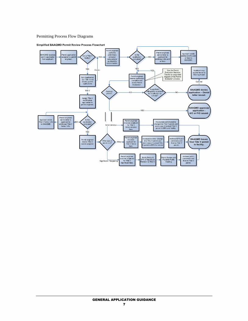
A flow diagram of the District’s permitting process is provided for illustrative purposes. A Frequently
Asked Questions document is available to answer the most commonly asked questions. If you cannot find
an answer to your question, you can phone the Engineering Division question line at (415) 749-4990.
Completeness Determination
Every application for an authority to construct or a permit to operate must include applicable District forms
and contain all of the information required for the APCO to make a decision on the application. Each of
the permit handbook chapters has a listing of the District forms and additional information required for
each of the sources in the various source categories. In addition, the permit handbook chapters refer to the
applicable fee calculation procedures to determine the required fee. A Completeness Determination
Checklist has been developed to aid in the preparation of a complete application.
If an application is not complete, the APCO shall notify the applicant in writing and indicate what
additional data or fees are required to complete the application. Typically, the District must review and
determine whether an application is complete within 15 working days of receipt of the application. The
APCO may cancel an application if the applicant fails to furnish the requested information or pay all
appropriate fees during the requested time frame. In general, the APCO notifies the applicant in writing of
the approval or denial of their application within 35 working days of receipt of a completed application.
However, the deadlines are different for certain special permit types:
Deposit Emission Reduction Credits;
Major Facility Review (Title V);
Prevention of Significant Deterioration (PSD);
Projects within 1000 feet of a school boundary;
Projects that require CEQA environmental review and documentation;
Projects that trigger publication, and public comment requirements of Regulation 2-2-
405, 2-4-405, or 2-9-405.
In addition, the deadlines may be extended upon mutual consent of the applicant and the APCO.
GENERAL APPLICATION GUIDANCE
7
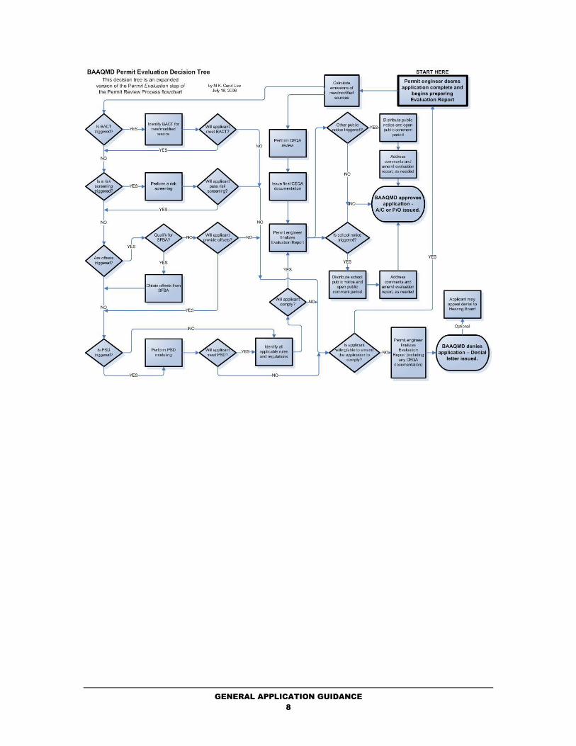
Permitting Process Flow Diagrams
GENERAL APPLICATION GUIDANCE
8

GENERAL APPLICATION GUIDANCE
9
GENERAL EVALUATION GUIDANCE by M.K. Carol Lee
October 23, 2018
Completeness Determination
Every application for an authority to construct or a permit to operate must include applicable District forms
and contain all of the information required for the APCO to make a decision on the application. Each of
the permit handbook chapters has a listing of the District forms and additional information required for
each of the sources in the various source categories. In addition, the permit handbook chapters refer to the
applicable fee calculation procedures to determine the required fee. A Completeness Determination
Checklist has been developed to aid in the preparation of a complete application.
If an application is not complete, the APCO shall notify the applicant in writing and indicate what
additional data or fees are required to complete the application. Typically, the District must review and
determine whether an application is complete within 15 working days of receipt of the application. The
APCO may cancel an application if the applicant fails to furnish the requested information or pay all
appropriate fees during the requested time frame. In general, the APCO notifies the applicant in writing of
the approval or denial of their application within 35 working days of receipt of a completed application.
However, the deadlines are different for certain special permit types:
Deposit Emission Reduction Credits;
Major Facility Review (Title V);
Prevention of Significant Deterioration (PSD);
Projects within 1000 feet of a school boundary;
Projects that require CEQA environmental review and documentation;
Projects that trigger publication, and public comment requirements of Regulation 2-2-
405, 2-4-405, or 2-9-405.
In addition, the deadlines may be extended upon mutual consent of the applicant and the APCO.
Evaluation Report
After a complete application has been provided, the permit evaluator prepares an “evaluation report” which
documents the evaluation and the resulting decision (approval or denial) of the application. The sections
within the evaluation report include a brief background description of the application, emission
calculations, applicable requirements, and recommended permit conditions. The following sections of this
guidance will provide the details to be considered in preparing the evaluation report. Evaluation Report
Template Guidance has been prepared to aid in the preparation of an evaluation report.
Background
The permit evaluator should include a background of the sources to be permitted. The background should
list the sources included in the permit application. Relevant historical information regarding sources (e.g.,
initial date of operation, if already operating, or proposed date of construction) should be included in the
background.
Emission Calculations
The emissions from the proposed source(s) will normally be calculated using the specific procedures and/or
emission factors referenced in the District’s Permit Handbook chapter for that source type. Deviations
from these procedures may make the permitting decision non-ministerial and therefore subject to CEQA.
Emission calculations should include all relevant criteria pollutants including toxic air contaminants (TAC)
{see District Unified TAC List for Public Notice, Schools} and for all relevant time periods:

GENERAL EVALUATION GUIDANCE
10
• Annual;
• Maximum daily; and
• Maximum 1-hour (if TAC has a acute trigger level listed in Table 2-5-1 of Regulation 2-
5)
Regulations 2-2-604 and 2-5-601 provide the emission calculation procedures for criteria pollutants and
TACs, respectively.
Applicable Requirements
For each source, the permit evaluator must list, and determine compliance with, each applicable
requirement identified in the District’s Permit Handbook chapter for the source type. A permit cannot be
approved without the source being in compliance with all applicable regulatory requirements.
District Rules and Regulations
The permit handbook chapters identify all applicable District rules that may apply to each specific source
type in each source category.
Best Available Control Technology (BACT)
In accordance with Regulation 2-2-301, BACT is triggered if emissions of Precursor Organic Compounds
(POC), Non-Precursor Organic Compounds (NPOC), Nitrogen Oxides (NOx), or Sulfur Dioxides (SO2)
exceed 10 pounds per highest day.
BACT for a source can be determined from the BACT/TBACT Workbook. The BACT determination
tables presented in the BACT/TBACT Workbook have two BACT levels of control as discussed
previously: 1) Technologically Feasible/Cost-Effective and 2) Achieved in Practice. The minimum BACT
level of control is the second category; the emission control or emission limitation has already been
generally achieved in practice. Then the user should look for a BACT entry in the first BACT level of
control, technologically feasible/cost-effective controls or emission limitations, and determine whether the
control or emission limitation is appropriate for the specific application under review. The fact that there is
a BACT Level 1 entry in the table indicates that a determination has already been made that the technology
is feasible and is potentially cost-effective. The Air Pollution Control Officer, with the assistance of District
staff, will make the final determination of the applicability of that BACT determination for the specific
source equipment, usage, and operating condition under review. Staff will also review the proposed
control equipment and/or emission control level for obsolescence, and determine whether a more efficient
control technique and/or more stringent emission limitation has been shown to be feasible and cost
effective. As discussed in the Cost Effectiveness Determination section, such factors as the material usage
or process throughput limits expected on the permit to operate will have a major impact on the final
determination. If no control technology or emission limitation in the "technologically feasible/cost-
effective" BACT1 category is applicable, then BACT reverts back to BACT2, the "achieved in practice
category," or to some intermediate level of control. If a source has been deemed subject to BACT1 control
requirements, then CEQA review is also triggered.
Offsets
In accordance with Regulation 2-2-302, offsets are triggered if a facility emits more than 10 ton per year of
POC or NOx. If the facility has potential emissions above 10 but below 35 tons per year of POC or NOx,
then the District shall provide the offsets from the Small Facility Bank, if the facility or its parent company
(see Policy: Clarification Regarding Provider of Emission Reductions Credits/Offsets) doesn’t already own
emission reduction credits held in a Banking Certificate. If the facility has emissions above 35 tons per
year, the facility shall provide the offsets. The District permit evaluator should indicate in the evaluation
report the quantity of offsets required and how offsets are provided. A permit cannot be approved without
the required offsets.
Prevention of Significant Deterioration (PSD)
In accordance with Regulation 2-2-304, 305, 306, and 308, PSD modeling is triggered for the following:

GENERAL EVALUATION GUIDANCE
11
1. A new major facility that will emit 100 tons per year or more from one of twenty eight (28) PSD
source categories listed in Section 169(1) of the federal Clean Air Act or 250 tons per year of more for
an unlisted category;
2. A major modification of a major facility if the cumulative increase from the PSD Baseline Date, as
defined in Regulation 2-2-204, minus the contemporaneous emission reduction credits at the facility
are in excess of the following:
a. 40 tons per year of sulfur dioxide or nitrogen dioxide; or
b. 15 tons per year of PM10; or
c. 0.6 tons per year of lead.
3. A major modification of a major facility with an increase of 100 tons per year or more of carbon
monoxide.
4. A new or modified facility if the new or modified facility will emit greater than 100 tons per year of
carbon monoxide, PM10, sulfur dioxide, precursor organic compounds or nitrogen oxides, and the
increase in emissions due to the permit application, minus the onsite contemporaneous emission
reduction credits associated with the permit application are in excess of the following annual average
amounts specified:
ANNUAL AVERAGE DAILY
kg/yr (ton/yr) g/day (lb/day)
Lead 530 (0.6) 1450 (3.2)
Asbestos 6 (0.007) 17 (0.04)
Beryllium 0.3 (0.0004) 0.9 (0.002)
Mercury 88 (0.1) 240 (0.5)
Fluorides 2720 (3) 7450 (16)
Sulfuric Acid Mist 6350 (7) 17400 (38)
Hydrogen Sulfide 9050 (10) 24800 (55)
Total Reduced Sulfur 9050 (10) 24800 (55)
Reduced Sulfur Compounds 9050 (10) 24800 (55)
5. A facility for which the cumulative increases minus the contemporaneous emission reduction credits
occurring since the PSD Baseline Date, are greater than zero, and which would construct in a Class 1
Area or within 10 kilometers (6.2 miles) of a Class 1 area, and would have an impact on such area
equal to or greater than 1 microgram per cubic meter.
A permit application cannot be approved unless the modeling analysis demonstrates that the proposed
source emissions will not interfere with the attainment or maintenance of a National Ambient Air Quality
Standard (NAAQS), and, if applicable, will not cause an exceedance of a Prevention of Significant (PSD)
increment. For District purposes, NAAQS is defined to include both California and national standards.
Guidance from the District’s Engineering Division is available for the applicant’s use to give the permit
applicant specific assumptions, requirements, conventions, and procedures for the preparation of a
modeling analysis. Because this guidance cannot cover every aspect of the analysis needed for a proposed
source without becoming unwieldy, the applicant should submit a modeling plan (protocol) with their
application before beginning the analysis.
The District permit evaluator shall include reference of the modeling analysis and summarize the results in
the evaluation report and attach the analysis to the evaluation report. If PSD modeling is triggered, then the
publication and public comment requirement of Regulation 2-2-405 is also triggered.
California Environmental Quality Act (CEQA)
Permit applications which are reviewed following the specific procedures, fixed standards and objective
measurements set forth in the District’s Permit Handbook will be classified as ministerial and will
accordingly be exempt from CEQA review per Regulation 2-1-311. In indicating that the permit
application is ministerial, the District permit evaluator should indicate in the evaluation report the permit
handbook chapter(s) that is being followed for the proposed source(s).
Notwithstanding the requirement of Regulation 2-1-311, the District may review on a case-by-case basis
permit applications to determine whether the District’s evaluation of the permit application will involve any
element of discretion. If as a result of this case-by-case review, the District determines that the evaluation

GENERAL EVALUATION GUIDANCE
12
of the permit application will not involve any element of discretion on its part, then the application may be
treated as a ministerial project, per Regulation 2-1-314, as long as the following conditions are met:
314.1 The District makes a specific written finding to this effect as part of its determination
that the permit application is complete;
314.2 The District will merely apply the law to the facts as presented in the permit
application; and
314.3 The District's evaluation of the permit application and its decision regarding whether
to issue the permit will be limited to the criteria set forth in Section 2-1-428.
In addition, the District has determined that source(s) that require BACT1 control technology may involve
elements of discretion and may trigger CEQA review. The permit engineer should follow the Determining
CEQA Applicability to Authority to Construct and/or Permit to Operate procedure for determining CEQA
applicability to evaluate whether CEQA is triggered.
In addition to ministerial projects, the following categories of permit applications will be exempt from
CEQA review: (Basis: Regulation 2-1-312), unless another agency has assumed responsibility as the lead
agency.
312.1 Applications to modify permit conditions for existing or permitted sources or
facilities, which do not involve any increases in emissions or physical modifications.
312.2 Permit applications to install air pollution control or abatement equipment.
312.3 Permit applications for projects undertaken for the sole purpose of bringing an
existing facility into compliance with newly adopted regulatory requirements of the
District or of any other local, state or federal agency.
312.4 Permit applications submitted by existing sources or facilities pursuant to a loss of a
previously valid exemption from the District's permitting requirements.
312.5 Permit applications submitted pursuant to the requirements of an order for abatement
issued by the District's Hearing Board or of a judicial enforcement order.
312.6 Permit applications relating exclusively to the repair, maintenance or minor
alteration of existing facilities, equipment or sources involving negligible or no
expansion of use beyond that previously existing.
312.7 Permit applications for the replacement or reconstruction of existing sources or
facilities where the new source or facility will be located on the same site as the
source or facility replaced and will have substantially the same purpose and capacity
as the source or facility replaced.
312.8 Permit applications for cogeneration facilities, which meet the criteria of Section
15329 of the State CEQA Guidelines.
312.9 Any other project, which is exempt from CEQA review pursuant to the State CEQA
Guidelines.
312.10 Applications to deposit emission reductions in the emissions bank pursuant to
Regulation 2, Rule 4 or Regulation 2, Rule 9.
312.11 Permit applications for a proposed new or modified source or sources or for process
changes which will satisfy the “No Net Emission Increase" provisions of District
Regulation 2, Rule 2, and for which there is no possibility that the project may have
any significant environmental effect in connection with any environmental media or
resources other than air quality. Examples of such projects include, but are not
necessarily limited to, the following:
11.1 Projects at an existing stationary source for which there will be no net increase
in the emissions of air contaminants from the stationary source and for which
there will be no other significant environmental effect;
11.2 A proposed new source or stationary source for which full offsets are provided
in accordance with Regulation 2, Rule 2, and for which there will be no other
significant environmental effect;
11.3 A proposed new source or stationary source at a small facility for which full
offsets are provided from a small facility bank established by the APCO

GENERAL EVALUATION GUIDANCE
13
pursuant to Regulation 2-4-414, and for which there will be no other
significant environmental effect;
11.4 Projects satisfying the "no net emission increase" provisions of District
Regulation 2, Rule 2 for which there will be some increase in the emissions of
any toxic air contaminant, but for which the District staff’s preliminary health
risk screening analysis shows that a formal health risk assessment is not
required, and for which there will be no other significant environmental effect.
Any permit applicant for any project that is not ministerial must include in its permit application the
following CEQA related information: (Basis: Regulation 2-1-426.1)
426.1 A preliminary environmental study which shall describe the proposed project and
discuss any potential significant adverse environmental impacts, alternatives to the
project, and any necessary mitigation measures to minimize adverse impacts. The
preliminary environmental study shall include all activities involved in the project
and shall not be limited to those activities affecting air quality. In preparing the
preliminary environmental study, the applicant may utilize the Environmental
Information Form in Appendix H of the State CEQA Guidelines or an equivalent
format specified by the APCO. (see also Appendix G, Significant Effects.) The
preliminary environmental study shall list all other local, state and federal
governmental agencies that require permits for the project and indicate any
environmental documentation required by such agencies; or
426.2 When an agency other than the District is to be the Lead Agency under CEQA,
either:
2.1 A Draft or Final Environmental Impact Report prepared by or under the
supervision of the Lead Agency; or
2.2 A contract for the preparation of a Draft Environmental Impact Report
executed by the Lead Agency together with the Initial Study prepared by the
Lead Agency; or
2.3 A Negative Declaration prepared by the Lead Agency; or
2.4 A Notice of Preparation of a Draft EIR prepared by the Lead Agency;
2.5 A copy of the Initial Study prepared by the Lead Agency, or
2.6 A commitment in writing from another agency indicating that it has assumed
the role of Lead Agency for the project in question.
In indicating that the permit application is exempt from CEQA review per Regulation 2-1-312, the District
permit evaluator shall indicate in the evaluation report the subsection within Subsection 312, which is
applicable, and ensure that a completed Appendix H Environmental Information Form or other required
CEQA documentation has been submitted with the application.
Notwithstanding the exemptions from CEQA review set forth in Regulation 2-1-312, such exemptions shall
not apply under the following circumstances:
(i) to any project for which the District staff’s preliminary health risk screening analysis shows
that a formal health risk assessment must be submitted by the applicant,
(ii) to any project covered by the categories set forth in subsections 2-1-312.1 through 312.9
where there is a reasonable possibility that the activity will have a significant effect on the
environment due to unusual circumstances, or due to cumulative impacts of successive
projects of the same type in the same place over time. Such projects shall be reviewed in
accordance with the requirements of CEQA.
If the permit application is subject to CEQA, then CEQA review is triggered. For those permit
applications, which must be reviewed in accordance with the requirements of CEQA, the District will not
normally be a Lead Agency under CEQA. Rather, pursuant to CEQA, the Lead Agency will normally be
an agency with general governmental powers, such as a city or county, rather than a special purpose agency
such as the District. However, if no Lead Agency exists, then the District must take on the role as Lead

GENERAL EVALUATION GUIDANCE
14
Agency and perform the required CEQA review. BAAQMD CEQA Guidelines are available, in addition to
the State of California’s website, to provide details on how to comply with the requirements.
School Notification
AB 3205 (H&S Code Section, 42301.6 through 42301.9) addresses sources of hazardous air pollutants near
schools. It requires new or modified sources of “hazardous air emissions” located within 1000 feet of the
outer boundary of a school to give public notice to the parents or guardians of children enrolled in any
school located within one-quarter mile of the source and to each address within a 1000-foot radius.
As a result, any new or modified source located within 1000 feet of the outer boundary of a school and
which results in the increase of any “hazardous air emissions” into the ambient air, triggers the public
notice requirement of Regulation 2-1-412. A school is defined as any public or private school of more than
12 children in kindergarten or any grades 1 to 12, excluding private schools in which education is primarily
conducted in private homes. H&S Code Section 42301.6(h)(1) defines “hazardous air emissions” as the
following:
"Hazardous air emissions" means emissions into the ambient air
of air contaminants which have been identified as a toxic air
contaminant by the state board or by the air pollution control
officer for the jurisdiction in which the project is located. As
determined by the air pollution control officer, hazardous air
emissions also means emissions into the ambient air from any
substances identified in subdivisions (a) to (f), inclusive, of
Section 44321 of the Health and Safety Code.”
As indicated in the definition, “hazardous air emissions” are identified on the following lists:
• AB2588 List
• Regulation 2-5, Table 2-5-1
• Proposition 65 List
• CalARP Program List
All four lists should be reviewed to determine whether the applicant will emit a “hazardous air emission”.
The permit evaluator should check whether the facility is located within 1000 feet of a school. The District
evaluator shall use the internal District “schools” program. [Applicants may use the following web sites to
check the facility location and the location of the nearest schools: MapQuest and GreatSchools.net.] If the
preliminary check indicates that the facility location is within 1500 feet of a school, then the permit
evaluator should contact the school(s) to verify that they are indeed a K-12 school of more than 12 children,
which is operating at the identified location. If the school is large enough to trigger public notice
requirements, the applicant must provide a satellite map showing 1) the location of the source, 2) the
boundary of the school, and 3) the scale of the map. Once one school is identified within 1000 feet, the
search radius must be enlarged to 0.25 mile (1320 feet) to determine whether there are more schools within
this new search radius. Once all the schools have been identified, and prior to approving any authority to
construct or permit to operate, a public notice must be distributed to all parents/guardians of students going
to the school and all addresses within 1000 feet of the school. The public notice shall describe the
proposed new or modified source, and the proposed emissions and allow 30 days for public comment. The
APCO shall review and consider all comments received during the 30 days after the notice is distributed,
and shall include a written response to the comments in the permit application file prior to taking final
action on the application.
Health Risk Screening Analysis (HRSA)
In accordance with Regulation 2-5, the total emissions of each applicable TAC from all new and modified
sources contained within a permit application shall constitute the “project” for the purpose of determining
whether an HRSA must be prepared. In addition, in order to prevent circumvention which might be
achieved by breaking a project into smaller pieces and submitting more than one permit application over a

GENERAL EVALUATION GUIDANCE
15
period of time, a project shall include those new or modified sources of TACs at a facility that have been
permitted within the two-year period immediately preceding the date a complete application is received,
unless the applicant demonstrates to the satisfaction of the APCO that construction or modification of the
sources included in the current application was neither (1) a reasonably foreseeable consequence of the
previous project, nor (2) a critical element or integral part of the previous project. If the estimated project
emission of any identified TAC exceeds its respective acute or chronic trigger level listed in Table 2-5-1 of
Regulation 2-5, then an HRSA is required for the project.
The permit evaluator should calculate TAC emission rates, including annual average emission rates, and
maximum hourly emission rates (if the TAC has an acute trigger level) to determine if an HRSA is
required. If an HRSA is required, the permit evaluator should submit a completed HRSA form with
accompanying facility plot plan and local street map indicating the location of the facility, the source
location(s), any surrounding building(s), application information from other new or modified sources of
TACs at the facility that have been permitted within the two-year period immediately preceding the date
the complete application was received, and a transmittal interoffice memorandum to the District’s Toxics
Section Manager. Regulation 2-5 dictates that the cancer risk is acceptable if it is below one in a million,
or if TBACT is applied and the cancer risk is below 10 in a million; the non-cancer risk is acceptable if the
chronic hazard index is less than or equal to 0.2, or if TBACT is applied and the chronic hazard index is
less than or equal to 1.0, and the acute hazard index is less than or equal to 1.0. The District permit
evaluator should summarize the risk assessment in the evaluation report. Unless the cancer and non-cancer
risks are acceptable in accordance with Regulation 2-5, a permit application cannot be approved.
Air Toxics Control Measures (ATCM)
The permit handbook chapters will identify any applicable ATCM that may apply for each specific source
type in each source category.
New Source Performance Standards (NSPS)
Section 111 of the Clean Air Act, "Standards of Performance of New Stationary Sources," requires EPA to
establish federal emission standards for source categories, which cause or contribute significantly to air
pollution. These standards are intended to promote use of the best air pollution control technologies, taking
into account the cost of such technology and any other non-air quality, health, and environmental impact
and energy requirements. These standards apply to sources, which have been constructed or modified since
the proposal of the standard. Since December 23, 1971, the Administrator has promulgated nearly 75
standards. These standards can be found in the Code of Federal Regulations at Title 40 (Protection of
Environment), Part 60 (Standards of Performance for New Stationary Sources).
The permit handbook chapters will identify any applicable NSPS that may apply for each specific source
type in each source category.
National Emissions Standards for Hazardous Air Pollutants (NESHAP)
The Federal Clean Air Act requires the Environmental Protection Agency (EPA) to regulate emissions of
toxic air pollutants from a published list of industrial sources referred to as "source categories." As required
under the Act, EPA has developed a list of source categories that must meet control technology
requirements for these toxic air pollutants. The EPA is required to develop NESHAP for all industries that
emit one or more of the pollutants in significant quantities in 40 CFR 63. In addition, in 40 CFR 61, they
also adopted NESHAPs based on control of certain types of hazardous pollutants.
The permit handbook chapters will identify any applicable NESHAP that may apply for each specific
source type in each source category. These standards are also called Maximum Achievable Control
Technology (MACT) standards. Most apply in the event that the facility is a Title V facility. However,
there are a few MACT standards that apply to small sources. The source-specific permit handbook
chapters will identify these cases.

GENERAL EVALUATION GUIDANCE
16
Permit Conditions
Standardized conditions for the various source types for each source category are available from each
permit handbook chapter and the Permit Condition Guidance. Deviations from standard permit conditions
must be clearly indicated in the permit evaluation, and may result in a project being deemed non-
ministerial, thereby triggering further CEQA review. Each of the permit handbook chapters contains
applicable permit conditions for each source type.
GENERAL EVALUATION GUIDANCE
17
PERMIT CONDITION GUIDANCE by M.K. Carol Lee
October 23, 2018
Background
Authorities to Construct or Permits to Operate may be subject to a permit conditions. A condition may
contain parts that limit material usage rates, set allowable operating parameter ranges, require emissions or
parametric monitoring, require compliance demonstration tests, or establish record keeping requirements,
per the Policy: Records Retention for Permit Conditions. The standardized permit conditions that are
provided in this guidance are to be used in uniform treatment of ministerial sources. Note that .doc
versions of these permit conditions are available from the Evaluation Report Template Guidance.
Condition Basis Codes
Each permit condition part limiting source operations shall include a basis code. Basis codes shall be based
on requirements in District, State, or Federal regulations. Limits should be deemed necessary to ensure a
source complies with that regulation. The following are abbreviations and descriptions for each basis code.
The Permit Engineer should use the abbreviated identifiers at the end of each part, and provide a legend at
the end of the condition text.
Abbreviation Description
BACT Best Available Control Technology, per Reg. 2-2-301;
Offsets Offset requirements of Reg. 2-2-302/303;
ERC Emission Reduction Credit from banked emissions.
IERC Interchangeable Emission Reduction Credit banking per Reg. 2-9;
PSD Prevention of Significant Deterioration, Reg. 2-2-304 through 306;
Toxic Health Risk Screen, per Regulation 2, Rule 5: New Source
Review of Toxic Air Contaminants;
NSPS New Source Performance Standard, Reg. 10;
NESHAPS National Emission Standard for Hazardous Air Pollutants, Reg. 11;
MACT Maximum Achievable Control Technology;
Cumulative Increase Cumulative emission increase, as defined in Regulation 2-2-212,
and as calculated in permit application; and
Other Provide a brief description.
Each part should usually have three sections:
1. Limit
2. Monitoring
3. Reporting/recordkeeping (see Policy: Records Retention for Permit Conditions)
Template Permit Conditions
An index of the various permit conditions is provided below:
2.1 Boilers, Steam Generators & Process Heaters
Natural Gas
Natural Gas w/Diesel Fuel Backup
Other Gas Fuel
Diesel Fuel
2.3 Internal Combustion Engines
Emergency Stationary Diesel Engines
Emergency Stationary Natural Gas Engines
Portable Diesel Engine
3.1 Bulk Loading
General

PERMIT CONDITION GUIDANCE
18
Marine
3.3 Oil-Water Separators
3.4 Petroleum Refinery Fugitive Emissions
3.5 Natural Gas Facilities and Crude Oil Facilities
4 Organic Liquid Storage Tanks
General Conditions (fixed roof tanks)
Additional for Internal or External Floating Roofs
Additional for Vapor Recovery System
5.1&5.3 Coating Operations (including Graphic Arts)
5.2 Coating, Adhesives, and Ink Manufacturing
Mixing Vats
Screening Mill
6 Solvent Cleaning
7.2 Wave Solder Machine
7.3 Flexible and Rigid Disc Manufacturing
7.4 Semiconductor Fabs
Abatement by thermal oxidation
Additional for Thermal Oxidizer RACT
Additional for source testing
Additional for allowable temperature excursion
Wastewater Treatment Facilities
Anaerobic Digester
9.1 Airstripping
Portable Airstripping or Soil Vapor Extraction Using Thermal Oxidation
Combined Airstripping and Soil Vapor Extraction Using Thermal or Catalytic
Oxidation and/or Activated Carbon Vessels Additional for carbon abatement
Carbon abatement
Additional for Thermal Oxidizer RACT
Additional for IC Engine RACT
Additional for end of remediation project
Additional for source testing
Additional for allowable temperature excursion
9.2 Soil Vapor Extraction
Conditions for Portable Airstripping or Soil Vapor Extraction Using Thermal
Oxidation
Conditions for Combined Airstripping and Soil Vapor Extraction Using Thermal or
Catalytic Oxidation and/or Activated Carbon Vessels Additional for carbon
abatement
Additional for Thermal Oxidizer RACT
Additional for IC Engine RACT
Additional for end of remediation project
Additional for source testing
Additional for allowable temperature excursion
10.1 Chrome Plating (Hexavalent)
Decorative Chrome Plating
Hard Chrome Plating
Trivalent Chrome Plating
10.2 Ethylene Oxide Sterilizer w/Catalytic Oxidation
Additional for Thermal Oxidizer RACT
Additional for allowable temperature excursion
10.4 Petroleum Solvent Dry Cleaning
10.5 Perchloroethylene Dry Cleaning
11.1 Abrasive Blasting
non-BACT with no abatement
non-BACT with abatement
BACT with abatement

PERMIT CONDITION GUIDANCE
19
11.2 Asphalt Drum Mixer
11.3 Coffee Roasters
11.4 Cooling Towers
11.5 Concrete Batch Plants
Abatement by Baghouse
11.6 Crematories
Human
Animal
11.7 Crushing and Grinding
Abatement by Baghouse
11.9 Miscellaneous Organic Operations
11.10 Portable Equipment
Portable Diesel Engine
Portable Tub Grinders w/Diesel Engines
11.11 Polyester Resin Manufacturing
11.12 Polyester Resin Operation
11.13 Tub Grinders
Powered by Electricity (stationary)
Powered by Diesel Engine (stationary)
The permit handbook chapters provide recommended permit conditions for each source type. Moreover,
additional parts may be added in circumstances when BACT-required abatement or other circumstances
warrant source testing and/or additional monitoring. These additional parts are identified below:
A. Abatement by Thermal Oxidizer
B. Allowable Temperature Excursions
C. Source Testing
D. Abatement by Carbon
E. Abatement by Baghouse
F. Thermal Oxidizer RACT
G. IC Engine RACT

PERMIT CONDITION GUIDANCE
20
July 18, 2006
Permit Conditions for Boilers, Steam Generators & Process Heaters, fired with fuel oil only:
1. The owner/operator shall not use more than gallons of diesel fuel at S- in any
consecutive twelve-month period. (basis: Cumulative Increase)
2. To determine compliance with the above part, the owner/operator shall maintain the monthly
records of diesel fuel consumption at S- in a District approved log. These logs shall be kept
for at least 2 years and shall be made available to the District upon request. (basis: Cumulative
Increase)
3. Within 60 days of startup, the owner/operator shall conduct a District approved source test of S-
to verify that it complies with the following emission factors when using diesel oil as a fuel:
NOx = ppm @ 3% O2
CO = ppm @ 3% O2
POC = ppm @ 3% O2
(basis: Cumulative Increase)

PERMIT CONDITION GUIDANCE
21
July 18, 2006
Permit Conditions for Boilers, Steam Generators & Process Heaters, fired with natural gas and fuel oil as
backup fuel:
1. The owner/operator of S- shall operate this source on natural gas fuel exclusively, except
that diesel fuel may be used when natural gas is unavailable and also to test the performance of the
source using diesel fuel. (basis: Cumulative Increase)
2. The owner/operator shall not use more than therms of natural gas fuel at S- in any
consecutive twelve-month period. (basis: Cumulative Increase)
3. The owner/operator shall not use more than gallons of diesel fuel in any consecutive
twelve-month period and only during times of natural gas curtailment and to test the performance
of the source using diesel fuel. (basis: Cumulative Increase)
4. To determine compliance with the above parts, the owner/operator shall maintain the monthly
records of natural gas and diesel fuel consumption at S- in a District approved log. These
logs shall be kept for at least 2 years and shall be made available to the District upon request.
(basis: Cumulative Increase)
5. Within 60 days of startup, the owner/operator shall conduct a District approved source test of S-
to verify that it complies with the following emission factors when using natural gas as a
fuel:
NOx = ppm @ 3% O2
CO = ppm @ 3% O2
POC = ppm @ 3% O2
(basis: Cumulative Increase)

PERMIT CONDITION GUIDANCE
22
July 18, 2006
Permit Conditions for Boilers, Steam Generators & Process Heaters, fired with natural gas only:
1. The owner/operator of S- shall operate this source on natural gas fuel exclusively. (basis:
Cumulative Increase)
2. The owner/operator shall not use more than therms of natural gas fuel at S- in any
consecutive twelve-month period. (basis: Cumulative Increase)
3. To determine compliance with the above parts, the owner/operator shall maintain the monthly
records of natural gas consumption at S- in a District approved log. These logs shall be kept
for at least 2 years and shall be made available to the District upon request. (basis: Cumulative
Increase)
4. Within 60 days of startup, the owner/operator shall conduct a District approved source test of S-
to verify that it complies with the following emission factors when using natural gas as a
fuel:
NOx = ppm @ 3% O2
CO = ppm @ 3% O2
POC = ppm @ 3% O2
(basis: Cumulative Increase)

PERMIT CONDITION GUIDANCE
23
July 18, 2006
Permit Conditions for Boilers, Steam Generators & Process Heaters, fired with other gaseous fuel:
1. The owner/operator of S- shall operate this source on gas fuel exclusively. (basis:
Cumulative Increase)
2. The owner/operator shall not use more than standard cubic feet of gas fuel at S-
in any consecutive twelve-month period. (basis: Cumulative Increase)
3. To determine compliance with the above parts, the owner/operator shall maintain the monthly
records of gas consumption at S- in a District approved log. These logs shall be kept
for at least 2 years and shall be made available to the District upon request. (basis: Cumulative
Increase)
4. Within 60 days of startup, the owner/operator shall conduct a District approved source test of S-
to verify that it complies with the following emission factors when using gas as a
fuel:
NOx = ppm @ 3% O2
CO = ppm @ 3% O2
POC = ppm @ 3% O2
(basis: Cumulative Increase)

PERMIT CONDITION GUIDANCE
24
October 23, 2018
Permit Conditions for Emergency Stationary Diesel Engines:
Operating for reliability-related activities is limited to hour per year per engine.
[Basis: “Regulation 2-5]
1. The owner or operator shall operate each emergency standby engine only for the following
purposes: to mitigate emergency conditions, for emission testing to demonstrate compliance with a
District, state or Federal emission limit, or for reliability-related activities (maintenance and other
testing, but excluding emission testing). Operating while mitigating emergency conditions or
while emission testing to show compliance with District, state or Federal emission limits is not
limited. [Basis: “Stationary Diesel Engine ATCM” section 93115, title 17, CA Code of
Regulations,subsection (e)(2)(A)(3) or (e)(2)(B)(3)]
2. The owner/operator shall operate each emergency standby engine only when a non-resettable
totalizing meter (with a minimum display capability of 9,999 hours) that measures the hours of
operation for the engine is installed, operated and properly maintained. [Basis:“Stationary Diesel
Engine ATCM” section 93115, title 17, CA Code of Regulations,subsection(e)(4)(G)(1)]
3. Records: The owner/operator shall maintain the following monthly records in a District-approved
log for at least 36 months from the date of entry (60 months if the facility has been issued a Title
V Major Facility Review Permit or a Synthetic Minor Operating Permit). Log entries shall be
retained on-site, either at a central location or at the engine’s location, and made immediately
available to the District staff upon request.
a. Hours of operation for reliability-related activities (maintenance and testing).
b. Hours of operation for emission testing to show compliance with emission limits.
c. Hours of operation (emergency).
d. For each emergency, the nature of the emergency condition.
e. Fuel usage for each engine(s).
[Basis: “Stationary Diesel Engine ATCM” section 93115, title 17, CA Code of Regulations,
subsection (e)(4)(I), (or, Regulation 2-6-501)]
4. At School and Near-School Operation:
If the emergency standby engine is located on school grounds or within 500 feet of any school
grounds, the following requirements shall apply:
The owner or operator shall not operate each stationary emergency standby diesel-fueled engine
for non-emergency use, including maintenance and testing, during the following periods:
Whenever there is a school sponsored activity (if the engine is located on school grounds)
Between 7:30 a.m. and 3:30 p.m. on days when school is in session.
“School” or “School Grounds” means any public or private school used for the purposes of the
education of more than 12 children in kindergarten or any of grades 1 to 12, inclusive, but does
not include any private school in which education is primarily conducted in a private home(s).
“School” or “School Grounds” includes any building or structure, playground, athletic field, or
other areas of school property but does not include unimproved school property.
[Basis: “Stationary Diesel Engine ATCM” section 93115, title 17, CA Code of Regulations,
subsection (e)(2)(A)(1)] or (e)(2)(B)(2)]

PERMIT CONDITION GUIDANCE
25
October 23, 2018
Permit Conditions for Emergency Stationary Natural Gas Engines:
1. Operating for reliability-related activities is limited to 100 hours per year per engine.
[Basis: Regulation 9-8-330.2]
2. The owner or operator shall operate each emergency standby engine only for the following
purposes: to mitigate emergency conditions, for emission testing to demonstrate compliance with a
District, state or Federal emission limit, or for reliability-related activities (maintenance and other
testing, but excluding emission testing). Operating while mitigating emergency conditions or
while emission testing to show compliance with District, state or Federal emission limits is not
limited. [Basis: Regulation 9-8-330]
3. The owner/operator shall operate each emergency standby engine only when a non-resettable
totalizing meter (with a minimum display capability of 9,999 hours) that measures the hours of
operation for the engine is installed, operated and properly maintained. [Basis: Regulation 9-8-
530]
4. Records: The owner/operator shall maintain the following monthly records in a District-approved
log for at least 24 months from the date of entry (60 months if the facility has been issued a Title
V Major Facility Review Permit or a Synthetic Minor Operating Permit). Log entries shall be
retained on-site, either at a central location or at the engine’s location, and made immediately
available to the District staff upon request.
a. Hours of operation for reliability-related activities (maintenance and testing).
b. Hours of operation (emergency).
c. For each emergency, the nature of the emergency condition.
d. Fuel usage for each engine(s).
[Basis: Regulation 9-8-502]

PERMIT CONDITION GUIDANCE
26
October 23, 2018
Permit Conditions for Portable Diesel Engine:
1. The owner/operator of S- Diesel Engine has been given a permit for a portable source and is
subject to Regulation 2-1-220.
2. 2The owner/operator shall not store or operate the sources in one location for more than 12
consecutive months, following the date of initial operation. Any backup or standby engine, which
replaces S-1 IC Engine at the same location and is intended to perform the same function will be
counted toward this time limitation. The owner/operator shall not move the equipment and then
return it to the same location in an attempt to circumvent the portable equipment time requirement.
(basis: Regulation 2-1-220.1 through 2-1-220.3, and 2-1-220.10)
3. The owner/operator shall not operate within 1000 feet of the outer boundary of any K-12 school
site. (basis: Regulation 2-1-220.4)
4. The owner/operator shall comply with Regulation 2, Rule 5. (basis: Regulation 2-1-220.5)
5. The owner/operator shall emit no more than 10 tons per year of each pollutant, including POC,
CO, NOx, PM10, NPOC or SO2. (basis: Regulation 2-1-220.7)
6. The owner/operator shall fire S- Diesel Engine exclusively with CARB diesel fuel. (basis:
Cumulative increase, BACT, Toxic Risk Screen; Section 93116.3(a) of the ATCM for Portable
Diesel Engines)
7. The owner/operator of S- Diesel Engine shall not operate for more than hours during
any calendar day. The total operation is limited to hours of operation in any consecutive
12-month period. [Note: To qualify for as a “low-use” engine, the engine operations cannot
exceed 80 hours in a calendar year. Also, if “low-use”, add Section 93116.3(b)(2)(B) of ATCM
for Portable Diesel Engines to basis.](basis: Cumulative increase, BACT, Toxic Risk Screen)
8. The owner/operator shall equip S- Diesel Engine with either:
a. a non-resettable totalizing meter that measures hours of operation for the engine; or
b. a non-resettable fuel usage meter, the maximum hourly fuel rate shall be used to convert
fuel usage to hours of operation.
(basis: Cumulative Increase)
9. To determine compliance with the above conditions, the owner/operator shall maintain the
following records and provide all of the data necessary to evaluate compliance with the above
conditions.
a. Daily hours of operation.
b. Daily consumption of diesel fuel (in gallons).
c. Hours of operation and amount of diesel fuel in parts a) and b) shall be totaled on a
rolling consecutive 12-month quarter basis.
d. The owner/operator shall record all records in a District-approved log. The
owner/operator shall retain the records with the equipment for two years, from the date of
entry, and make them available for inspection by District staff upon request. These
record-keeping requirements shall not replace the record-keeping requirements contained
in any applicable District Regulations.
(basis: Toxic Risk Screen, Cumulative Increase, Regulation 1-441)
10. The owner/operator shall notify the Director of the Compliance and Enforcement Division, in
writing, at least 3 days in advance, of the new location in which it intends to operate. The
notification shall include:
a. Permit number

PERMIT CONDITION GUIDANCE
27
b. Brief description of the nature of the operation
c. Estimated duration of the operation at the new location
d. Name and telephone number of a contact person at the new location
(basis: Regulation 2-1-220)
11. Within 30 days after the end of the calendar year, the owner/operator shall provide the Director of
the Compliance and Enforcement Division a year-end summary with the following information:
a. The location(s) and dates at which the equipment was operated.
b. The total amount of diesel fuel consumed in this operation for the previous 12 months (in
gallons).
c. The total hours of operation.
(basis: Regulation 2-1-220)
[The following condition applies only to “in-use” portable diesel engines:]
12. Effective January 1, 2010, the owner/operator of S- Diesel Engine shall comply with one of
the following:
a. S- Diesel Engine complies with the Tier emission standards. A copy of its
CARB certification or approved source test data is submitted to the District’s Engineering
Division for review.
b. The owner/operator submits a permit application to replace S- Diesel Engine with a
portable diesel-fueled engine certified to the Tier 4 emission standards.
(basis: Section 93116.3(b)(2)(A) of ATCM for Portable Diesel Engines)
[The following condition applies only to “low-use” or “emergency” portable diesel engines:]
13. Effective January 1, 2020, the owner/operator of S- Diesel Engine shall comply with one of
the following:
a. S- Diesel Engine complies with Tier 4 emission standards for newly manufactured
nonroad engines.
b. The owner/operator submits a permit application to equip S- Diesel Engine with a
properly functioning level-3 verified technology.
c. The owner/operator submits a permit application to equip S- Diesel Engine with a
combination of verified emission control strategies that have been verified together to
achieve at least 85% reduction in diesel PM.
d. The owner/operator submits a permit application to replace S- Diesel Engine with a
portable diesel-fueled engine certified to the Tier 4 emission standards.
(basis: Section 93116.3(b)(3) of ATCM for Portable Diesel Engines)

PERMIT CONDITION GUIDANCE
28
October 23, 2018
Permit Conditions for Bulk Loading:
1. The owner/operator of A- Vapor Recovery Unit shall receive obtain appropriate certification
from the California Air Resources Board (CARB) for installation of the modified new equipment
prior to commencement of operation. (Basis: Reg.8-33)
2. The owner/operator of A- shall install a District approved exhaust flow measurement and
continuous hydrocarbon emission monitor at each exhaust outlet of the vapor recovery system.
This monitor shall continuously measure hydrocarbon concentration in parts per million as C1.
(Basis: Cumulative Increase)
3. Within 30 days of startup, the owner/operator of A- shall perform necessary source testing
to establish a relationship between the organic emission concentration measured on the continuous
hydrocarbon monitor and the corresponding emission rate in pounds per 1000 gallons of gasoline
loaded. This test shall establish the maximum allowable organic concentration level that meets the
pounds organic per 1000 gallons of gasoline loaded criteria of . The owner/operator
of A- shall submit the source test report to the District within 30 days of the test. (Basis:
Offsets/Cumulative increase)
4. Within 30 days of start up of the modified A- Vapor Recovery Unit, the owner/operator
shall conduct a District approved source test to demonstrate compliance with all applicable
sections of District Regulation 8, Rule 33 "Gasoline Bulk Terminals and Gasoline Delivery
Vehicles." This test will be used to establish the following:
a. Maximum gasoline loading rate (gallons per calendar day)
b. Maximum Refrigeration Unit discharge temperature.
(Basis: Cumulative Increase)
5. The total amount of fuel loaded at source S- shall not exceed gallons during
any consecutive twelve-month period. (Basis: Cumulative Increase)
6. To demonstrate compliance with the above, the owner/operator shall maintain the following daily
records in a District-approved log:
a. The type and amount of petroleum material loaded
b. Date of each loading event
All records shall be retained on site for at least two years from the date of entry, and be made
available for inspection by District staff on request. (Basis: Recordkeeping)

PERMIT CONDITION GUIDANCE
29
October 23, 2018
Permit Conditions for Marine Loading/Offloading Facility:
1. The Marine Loading/Offloading Facility (S- ) and its associated equipment shall be properly
maintained and leak free at all time. ( Basis: Regulation 8-44-304)
2. The total amount of fuel loaded at source S- shall not exceed gallons during
any consecutive twelve-month period. (Basis: Cumulative Increase)
3. The POC emissions from source S- shall not exceed 2 pounds per 1000 barrels of diesel or
jet fuel loaded. (Basis: Regulation 8-44-301.1)
4. To demonstrate compliance with the above, ARCO shall maintain the following daily records in a
District-approved log:
a. The type and amount of petroleum material loaded
b. Date of each loading event
c. The identification/name of each marine vessel calling at the dock
All records shall be retained on site for at least two years from the date of entry, and be made
available for inspection by District staff on request. (Basis: Recordkeeping)

PERMIT CONDITION GUIDANCE
30
October 23, 2018
Permit Conditions for Oil-Water Separator:
1. The owner/operator of S- shall not exceed wastewater throughput limits of gallons
during any consecutive twelve-month period. (Basis: Cumulative Increase)
2. To determine compliance with the above part, the owner/operator shall maintain the following
records:
a. Quantities of wastewater processed on a monthly basis.
b. Monthly throughput shall be totaled for each consecutive twelve-month period.
All records shall be retained on-site for two years, from the date of entry, and made available for
inspection by District staff upon request. These recordkeeping requirements shall not replace the
recordkeeping requirements contained in any applicable District Regulations.
(Basis: Cumulative Increase)

PERMIT CONDITION GUIDANCE
31
October 23, 2018
Permit Conditions for Petroleum Refinery Fugitive Emissions:
1. Not more than 30 days after the start-up of S- , the owner/operator shall provide the
District’s Engineering Division with a final count of fugitive components installed. The
owner/operator has been permitted for an increase in the following fugitive components:
valves in gas service
valves is liquid service
pumps
PRV in gas service
PRVs in liquid service
connectors/flanges
(basis: Cumulative Increase, offsets, toxics risk screen)
2. If there is an increase in the total fugitive component emissions, the plant’s cumulative emissions
for the project shall be adjusted to reflect the difference between emissions based on predicted
versus actual component counts. The owner/operator shall provide to the District all additional
required offsets at an offset ratio of 1.15:1 no later than 14 days after submittal of the final POC
fugitive count. If the actual component count is less than the predicted, the total will be adjusted
accordingly and all emission offsets applied by the owner/operator in excess of the actual total
fugitive emissions will be credited back to the owner/operator. (basis: offsets)
3. The owner/operator shall install valves, in light hydrocarbon service, that are of District approved
BACT compliant technology (bellows valves, diaphragm valves, live loaded valves, or the
equivalent) such that fugitive organic emissions shall not exceed 100 ppm. (basis: BACT,
Regulation 8-18, toxics risk screen)
4. The owner/operator shall install flanges and connectors, in light hydrocarbon service, that are of
District approved BACT compliant technology (graphitic gaskets or the equivalent) such that
fugitive organic emissions shall not exceed 100 ppm. (basis: BACT, Regulation 8-18, toxics risk
screen)
5. The owner/operator shall install pump seals, in light hydrocarbon service, that are of District
approved BACT compliant technology (double mechanical seals with barrier fluid or the
equivalent) such that fugitive organic emissions shall not exceed 500 ppm. (basis: BACT,
Regulation 8-18, toxics risk screen)
6. The owner/operator shall ensure that each pressure relief valve installed in hydrocarbon service is
vented back to the process, to the refinery fuel gas system, or to an abatement device with a
capture and destruction efficiency of at least 98% by weight. (basis: BACT, Regulation 8-28,
toxics risk screen)
7. In accordance with the provisions of Regulation 8-18, the owner/operator shall integrate all new
fugitive equipment in organic service installed as part of the S- into the facility fugitive
equipment monitoring and repair program. (basis: BACT, Regulation 8-18)
PERMIT CONDITION GUIDANCE
32
September 16, 2013
Permit Conditions for Natural Gas Production Facilities and Crude Oil Production Facilities:
Conditions for S- Dehydrator
1. The owner/operator of S- shall not exceed the following dry gas flow rates:
MMSCF per day
(Basis: Cumulative Increase)
2. The owner/operator of S- shall not use stripping gas. (Basis: Cumulative Increase,
Regulation 2-5)
3. The owner/operator of S- shall ensure that all emissions from the reboiler stack of S-
shall be abated at all times of operation by routing the emissions first to the gallon cooling
tank and then to the reboiler burner of S- . (Basis: Cumulative Increase)
4. The owner/operator of S- shall ensure that all emissions from the flash tank of S- shall
be abated at all times of operation by routing the emissions to the reboiler burner of S- as
fuel gas. (Basis: Cumulative Increase)
5. The owner/operator of S- shall not exceed the following limits for the combined emissions
from the regenerator vent and flash gas at any time.
Combined Regenerator Vent/Flash Gas Emission Limit
Benzene lb/hr lb/yr
VOC* lb/hr lb/yr
* Non-methane Hydrocarbon
(basis: Cumulative Increase, Toxics)
6. The owner/operator of S- Natural Gas Dehydrator including Reboiler and A- Air-
Condenser Tank shall ensure that District approved sample ports are installed in the following
locations for use during District approved source tests to measure emissions of benzene and
VOCs.
a. Regenerator vent stack (regenerator emissions before abatement)
b. A- Air-Condenser tank vent (regenerator emissions after abatement)
c. Reboiler exhaust stack (flash gas emissions after abatement)
(basis: Cumulative Increase, Toxics)
7. Within 60 days of startup and annually within the months of June through August, the
owner/operator shall source test each of the locations in part 6 under the following conditions:
a. The dehydrator shall run at maximum capacity.
b. The specification for the dry gas shall be lb water per million cubic feet or less.
c. The test shall consist of determining the flowrates at each point; taking a sample for lab
analysis; determining the concentration of the following components: VOC, benzene; and
determining the hourly mass emission rates of VOC and benzene.
If the District’s Source Test Division performs the above test, the permit holder may use the
results of the test in lieu of a separate test. The owner/operator shall submit individual copies of
the results of the source tests to the District’s Engineering Division, Enforcement Division, and
Source Test Division within 30 days of the source test. (basis: Cumulative Increase, Toxics)
Conditions for S- Storage Tank (from Permit Handbook Chapter 4)
PERMIT CONDITION GUIDANCE
33
8. The owner/operator of S- shall not exceed the following throughput limits during any
consecutive twelve-month period:
{Liquid #1} Gallons
{Liquid #2} Gallons
(Basis: Cumulative Increase)
9. The owner/operator may store alternate liquid(s) other than the materials specified in Part 8 and/or
usages in excess of those specified in Part 8, provided that the owner/operator can demonstrate
that all of the following are satisfied:
a. Total POC emissions from S- do not exceed pounds in any consecutive twelve
month period;
b. Total NPOC emissions from S- do not exceed pounds in any consecutive twelve
month period; and
c. The use of these materials does not increase toxic emissions above any risk screening
trigger level of Table 2-5-1 in Regulation 2-5.
(Basis: Cumulative Increase; Toxics)
10. To determine compliance with the above parts, the owner/operator shall maintain the following
records and provide all of the data necessary to evaluate compliance with the above parts,
including the following information:
a. Quantities of each type of liquid stored at this source on a monthly basis.
b. If a material other than those specified in Part 8 is stored, POC/NPOC and toxic
component contents of each material used; and mass emission calculations to
demonstrate compliance with Part 9, on a monthly basis;
c. Monthly throughput and/or emission calculations shall be totaled for each consecutive
twelve-month period.
All records shall be retained on-site for two years, from the date of entry, and made available for
inspection by District staff upon request. These recordkeeping requirements shall not replace the
recordkeeping requirements contained in any applicable District Regulations. (Basis: Cumulative
Increase; Toxics)
Permit Conditions for S- Oil-Water Separator (from Permit Handbook Chapter 3.3)
11. The owner/operator of S- shall not exceed wastewater throughput limits of gallons during
any consecutive twelve-month period. (Basis: Cumulative Increase)
12. To determine compliance with the above part, the owner/operator shall maintain the following
records:
a. Quantities of wastewater processed on a monthly basis.
b. Monthly throughput shall be totaled for each consecutive twelve-month period.
All records shall be retained on-site for two years, from the date of entry, and made available for
inspection by District staff upon request. These recordkeeping requirements shall not replace the
recordkeeping requirements contained in any applicable District Regulations. (Basis: Cumulative
Increase)
Conditions for S- Natural Gas-Fired Engine
13. The owner/operator shall operate S- engine only when NOx, CO and POC emissions are
abated by the properly maintained and properly operated A- 3-Way Catalyst. (Basis:
Cumulative Increase)
14. The owner/operator of S- shall not exceed the following limits: ppmv of NOx
corrected to 15% oxygen, dry Basis, ppmv of CO corrected to 15% oxygen, dry Basis.
(Basis: Regulation 9-8-301, Cumulative Increase)

PERMIT CONDITION GUIDANCE
34
15. The owner/operator of S- shall demonstrate compliance with the emissions limits of Part 14
by use of a portable analyzer to take NOx and CO emission readings. Reading shall be taken at
least once each calendar quarter in which a source test is not performed. All emissions readings
shall be taken with the engine operating at conditions representative of normal operations. NOx
emissions readings shall be averaged over a consecutive 15-minute period. (Basis: Regulation 9-
8-503)
16. Within 60 calendar days of permit issuance under Application , the owner/operator of S-
shall conduct a District approved source test at the outlet of A- to demonstrate
compliance with Part 14 and with Regulation 9-8-301.1. The owner/operator shall notify the
District’s Source Test Section, in writing, of the source test protocol and projected test date at least
7 days prior to testing. The owner/operator shall submit the source test results of S- to the
District’s Source Test Section no later than 30 days after the source test. This condition does not
replace any other regulatory requirement to conduct source tests. (Basis: Regulation 9-8-301,
Cumulative Increase)
17. To determine compliance with the above parts, the owner/operator shall maintain the following
records and provide all of the data necessary to evaluate compliance with the above parts,
including the following information:
a. Each monitor reading or analysis result for the day of operation that the monitoring
reading or analysis result is taken.
b. All source test data results.
All records shall be retained on-site for two years, from the date of entry, and made available for
inspection by District staff upon request. These recordkeeping requirements shall not replace the
recordkeeping requirements contained in any applicable District Regulations. (Basis:
Recordkeeping)
Conditions for S- Injection Wells
18. The owner/operator of S- shall reinject all gas from the facility, including all gas from S-
Tank and all excess gas from S- Crude Oil Wells, into the gas injection well of S-
. Excess gas from S- Crude Oil Wells is defined as all gas from S- that is not
consumed as fuel by S- engine. (Basis: Cumulative Increase)
19. The owner/operator of S- shall reinject all produced water from the facility into the water
injection well of S- . (Basis: Cumulative Increase)
Facility-Wide Conditions
20. The owner/operator shall not exceed the following fugitive component counts at the facility:
valves in service
connectors in service
flanges in service
miscellaneous components in service
(Basis: Cumulative Increase)
21. The owner/operator shall ensure that the concentration of organic compounds at every valve,
flange, connector, compressor, or pump shall be inspected every calendar quarter. The first
inspection shall take place within 60 days of issuance of the permit to operate pursuant to
Application . The inspections shall be shall be conducted as prescribed by EPA Reference
Method 21 (40 CFR 60, Appendix A). Any instrument used for the measurement of organic
compounds shall be a combustible gas detector or any other type of instrument approved by the
APCO that meets the specifications and performance criteria of, and is calibrated in accordance
with, EPA Reference Method 21. (Cumulative Increase, Regulation 8-37)

PERMIT CONDITION GUIDANCE
35
22. The owner/operator shall ensure that any valve, flange, connector, compressor, or pump that leaks
total organic compounds in excess of 10,000 ppm as C1 shall be minimized within 24 hours and
repaired within 7 days. (Basis: Cumulative Increase)
23. The owner/operator shall not exceed emissions of pounds TOC in any consecutive 12-
month period from all components listed in Part 20. This emissions limit includes emissions from
non-leaking components and from pegged leakers. Pegged leakers are defined as components
leaking at or greater 10,000 ppmv measured as C1. Compliance with Part 23 is achieved if the
number of days identified under Part 25d does not exceed 90 days in any consecutive 12-month
period.
If the number of days identified under Part 25d exceeds 90 days in any consecutive 12-month
period, the owner/operator shall calculate the actual TOC emissions from all components using the
measured leak concentrations determined under Part 25b, and compliance with Part 23 is achieved
if the calculated actual TOC emissions from all components does not exceed pounds in any
consecutive 12-month period. (Basis: Cumulative Increase)
24. The owner/operator shall assign an identification code to each valve, flange, connector,
compressor, pump seal, and miscellaneous component. The facility shall keep the following
records: The fitting identification code, the date of each inspection, and the corresponding leak
concentration measured. Records shall be maintained for at least 5 years and shall be made
available for inspection by District staff upon request. (basis: Cumulative Increase,
Recordkeeping)
25. To determine compliance with the above parts, the owner/operator shall maintain a monthly log of
the following records and provide all of the data necessary to evaluate compliance with the above
parts, including the following information:
a. Identification code of each component.
b. Date of each inspection, and the corresponding leak concentration measured.
c. Number of days that each individual component leaks at or greater than 10,000 ppmv
(measured as C1), type of component, identification number of component.
d. The total number of days identified in Part 25c.
e. Each monitor reading or analysis result for the day of operation that the monitoring
reading or analysis result is taken.
All records shall be retained on-site for two years, from the date of entry, and made available for
inspection by District staff upon request. These recordkeeping requirements shall not replace the
recordkeeping requirements contained in any applicable District Regulations. (Basis:
Recordkeeping)
26. The owner/operator shall ensure that there shall be no open liquid pools of crude oil or condensate
in the lease area. (Basis: Cumulative Increase, Regulation 8-37-302)
27. The owner/operator shall ensure that all spills of crude oil and condensate which causes a liquid
pool shall be cleaned up by removal of the liquid within 24 hours of the spill detection. (Basis:
Cumulative Increase, Regulation 8-37-304)
28. The owner/operator shall ensure that no open or uncovered vessels of crude material larger than
250 ml shall be kept in the lease area. (Basis: Cumulative Increase, Regulation 8-37-303)
29. The owner/operator of S- Tank shall ensure that all access hatches shall remain closed
except during active maintenance or repairs. (Basis: Cumulative Increase, Regulation 8-37-308)
30. The owner/operator shall properly install, use, and maintain vapor tight piping rated for
oil/gas/water service at this facility. (Basis: Cumulative Increase)

PERMIT CONDITION GUIDANCE
36
31. The owner/operator shall properly install, operate, and maintain all pressure relief protection
equipment at this facility. (Basis: Cumulative Increase)
32. The owner/operator shall not install and shall not use pneumatic devices at this facility. (Basis:
Cumulative Increase)
33. The owner/operator shall ensure that there are no open ended lines at this facility. (Basis:
Cumulative Increase)
34. Within 60 days of issuance of the Authority to Construct for Application , the
owner/operator shall conduct a pressure decay test for the produced gas system to demonstrate its
structural integrity and to demonstrate compliance with Part 30. The owner/operator shall notify
the District’s Source Test Section, in writing, of the test protocol and projected test date at least 7
days prior to testing. The owner/operator shall submit the test results to the District’s Source Test
Section no later than 30 days after the source test. (Basis: Cumulative Increase)
35. The owner/operator shall report non-compliance with any of the above conditions within 10 days
of discovering such non-compliance. The report shall be sent to:
Director of Compliance and Enforcement
Bay Area Air Quality Management District
939 Ellis Street
San Francisco, CA 94109
(Basis: Regulation 2-1-403)
PERMIT CONDITION GUIDANCE
37
July 18, 2006
Permit Conditions for Storage Tanks (general conditions):
1. The owner/operator of S- shall not exceed the following throughput limits during any
consecutive twelve-month period:
{Liquid #1} Gallons
{Liquid #2} Gallons
(Basis: Cumulative Increase)
2. The owner/operator may store alternate liquid(s) other than the materials specified in Part 1 and/or
usages in excess of those specified in Part 1, provided that the owner/operator can demonstrate
that all of the following are satisfied:
a. Total POC emissions from S- do not exceed pounds in any consecutive
twelve month period;
b. Total NPOC emissions from S- do not exceed pounds in any consecutive
twelve month period; and
c. The use of these materials does not increase toxic emissions above any risk screening
trigger level of Table 2-5-1 in Regulation 2-5.
(Basis: Cumulative Increase; Toxics)
3. To determine compliance with the above parts, the owner/operator shall maintain the following
records and provide all of the data necessary to evaluate compliance with the above parts,
including the following information:
a. Quantities of each type of liquid stored at this source on a monthly basis.
b. If a material other than those specified in Part 1 is stored, POC/NPOC and toxic
component contents of each material used; and mass emission calculations to
demonstrate compliance with Part 2, on a monthly basis;
c. Monthly throughput and/or emission calculations shall be totaled for each consecutive
twelve-month period.
All records shall be retained on-site for two years, from the date of entry, and made available for
inspection by District staff upon request. These recordkeeping requirements shall not replace the
recordkeeping requirements contained in any applicable District Regulations. (Basis: Cumulative
Increase; Toxics)

PERMIT CONDITION GUIDANCE
38
July 18, 2006
Permit Conditions for Storage Tanks (additional conditions for internal or external floating roofs):
4. The owner/operator of S- shall equipped the source with a liquid mounted primary seal and
a zero-gap secondary seal. There shall be no ungasketed roof fittings. Except for roof legs, each
roof fitting shall be of the design, which yields the minimum roof fitting losses (per EPA
Compilation of Air Pollution Emission Factors, AP-42, Supplement E, Section 12.3.2, Table 12.3-
11). The following list indicates the type of control required for a variety of typical roof fittings.
Control techniques for roof fittings not included in this list shall be subject to District approval,
prior to installing the roof on the tank.
Fitting Type Control Technique
Access hatch Bolted cover, gasketed
Guide pole / Well Unslotted guide pole, gasketed
sliding cover; or Slotted
with controls per API
2517 Addendum (See
Note 1)
Gauge float well Bolted cover, gasketed
Gauge hatch / Sample well Weighted mechanical actuation,
gasketed
Vacuum breaker Weighted mechanical actuation,
gasketed
Roof drain Roof drain does not drain water
into product
Roof leg Fixed; or adjustable with vapor seal
boot, or gasket between
roof leg and leg sleeve
Rim vent Weighted mechanical actuation,
gasketed
Note 1: Slotted Guide Pole Control Configuration, per Addendum to API Publication 2517, May
1994, shall include to following components:
a. Sliding cover;
b. Well gasket;
c. Pole sleeve with pole wiper approximately 6 inches above sliding cover, or District
approved equivalent;
d. Float with float wiper approximately 1 inch above the sliding cover, or alternately a float
with multiple wipers.
(Basis: BACT)
PERMIT CONDITION GUIDANCE
39
July 18, 2006
Permit Conditions for Vapor Recovery Systems:
1. The owner/operator of S- shall abate the source with A- , Vapor Recovery System
with , with an overall collection and destruction efficiency of at least 95%, by weight (basis:
Regulation 8-5-311.3)

PERMIT CONDITION GUIDANCE
40
July 18, 2006
Permit Conditions for Coating Operations (including Graphic Arts):
1. The owner/operator of S- shall not exceed the following usage limits during any consecutive
twelve-month period:
{Coating or Ink #1} Gallons
{Coating or Ink #2} Gallons
{Cleanup Solvent or Blanket Wash #1} Gallons
{Cleanup Solvent or Blanket Wash #2} Gallons
{Other #1} Gallons
{Other #2} Gallons
(Basis: Cumulative Increase)
2. The owner/operator may use an alternate coating(s) or cleanup solvent(s) other than the materials
specified in Part 1 and/or usages in excess of those specified in Part 1, provided that the
owner/operator can demonstrate that all of the following are satisfied:
a. Total POC emissions from S- do not exceed pounds in any consecutive
twelve month period;
b. Total NPOC emissions from S- do not exceed pounds in any consecutive
twelve month period; and
c. The use of these materials does not increase toxic emissions above any risk screening
trigger level of Table 2-5-1 in Regulation 2-5.
(Basis: Cumulative Increase; Toxics)
3. To determine compliance with the above parts, the owner/operator shall maintain the following
records and provide all of the data necessary to evaluate compliance with the above parts,
including the following information:
a. Quantities of each type of coating and cleanup solvent used at this source on a monthly
basis.
b. If a material other than those specified in Part 1 is used, POC/NPOC and toxic
component contents of each material used; and mass emission calculations to
demonstrate compliance with Part 2, on a monthly basis;
c. Monthly usage and/or emission calculations shall be totaled for each consecutive twelve-
month period.
All records shall be retained on-site for two years, from the date of entry, and made available for
inspection by District staff upon request. These recordkeeping requirements shall not replace the
recordkeeping requirements contained in any applicable District Regulations. (Basis: Cumulative
Increase; Toxics)

PERMIT CONDITION GUIDANCE
41
October 23, 2018
Permit Conditions for Mixing Vats for Coating, Adhesives, and Ink Manufacturing:
1. The owner/operator of S- shall not exceed the following throughput limits during any
consecutive twelve-month period:
{Coating or Ink Component #1} Gallons
{Coating or Ink Component #2} Gallons
{Coating or Ink Component #3} Gallons
{Coating or Ink Component #4} Gallons
{Cleanup Solvent #1} Gallons
{Cleanup Solvent #2} Gallons
(Basis: Cumulative Increase)
2. To determine compliance with the above part, the owner/operator shall maintain the following
records and provide all of the data necessary to evaluate compliance with the above parts,
including the following information:
a. Quantities of each type of component listed in Part 1 used at this source on a monthly
basis.
b. Monthly throughput shall be totaled for each consecutive twelve-month period.
All records shall be retained on-site for two years, from the date of entry, and made available for
inspection by District staff upon request. These recordkeeping requirements shall not
replace the recordkeeping requirements contained in any applicable District Regulations.
(Basis: Cumulative Increase)
3. The owner/operator of S- shall comply with the requirements of Regulation 8-35-301 and
305 in maintenance of the source and its cleaning. (Basis: Regulation 8-35-301 and 305)

PERMIT CONDITION GUIDANCE
42
October 23, 2018
Permit Conditions for Screening Mill for Coating, Adhesives, and Ink Manufacturing:
1. The owner/operator of S- shall not exceed the following throughput limits during any
consecutive twelve-month period:
{Coating Pigment#1} Gallons
{Coating Pigment #2} Gallons
(Basis: Cumulative Increase)
2. To determine compliance with the above part, the owner/operator shall maintain the following
records and provide all of the data necessary to evaluate compliance with the above parts,
including the following information:
a. Quantities of each type of component listed in Part 1 used at this source on a monthly
basis.
b. Monthly throughput shall be totaled for each consecutive twelve-month period.
All records shall be retained on-site for two years, from the date of entry, and made available for
inspection by District staff upon request. These recordkeeping requirements shall not replace the
recordkeeping requirements contained in any applicable District Regulations. (Basis: Cumulative
Increase)
3. The owner/operator of S- shall comply with the requirements of Regulation 8-35-304.
(Basis: Regulation 8-35-304)
PERMIT CONDITION GUIDANCE
43
July 18, 2006
Permit Conditions for Solvent Cleaning Operations:
1. The owner/operator of S- shall not exceed the following usage limits during any consecutive
twelve-month period:
{Solvent #1} Gallons
{Solvent #2} Gallons
(Basis: Cumulative Increase)
2. The owner/operator may use an alternate solvent(s) other than the materials specified in Part 1
and/or usages in excess of those specified in Part 1, provided that the owner/operator can
demonstrate that all of the following are satisfied:
a. Total POC emissions from S- do not exceed pounds in any consecutive
twelve-month period;
b. Total NPOC emissions from S- do not exceed pounds in any consecutive
twelve-month period; and
c. The use of these materials does not increase toxic emissions above any risk screening
trigger level of Table 2-5-1 in Regulation 2-5.
(Basis: Cumulative Increase; Toxics)
3. To determine compliance with the above parts, the owner/operator shall maintain the following
records and provide all of the data necessary to evaluate compliance with the above parts,
including the following information:
a. Quantities of each type of solvent used at this source on a monthly basis.
b. If a material other than those specified in Part 1 is used, POC/NPOC and toxic
component contents of each material used; and mass emission calculations to
demonstrate compliance with Part 2, on a monthly basis;
c. Monthly usage and/or emission calculations shall be totaled for each consecutive twelve-
month period.
All records shall be retained on-site for two years, from the date of entry, and made available for
inspection by District staff upon request. These recordkeeping requirements shall not replace the
recordkeeping requirements contained in any applicable District Regulations.
(Basis: Cumulative Increase; Toxics)

PERMIT CONDITION GUIDANCE
44
October 23, 2018
Permit Conditions for Wave Solder Flux Applicator:
1. The owner/operator shall not use more than gallons of flux and thinner (net) at S- in
any consecutive twelve-month period. (basis: Cumulative Increase)
2. The owner/operator of S- shall minimize emissions by covering or emptying the flux bath
when S- is not operating. (basis: Cumulative Increase)
3. In order to demonstrate compliance with Part 1, the owner/operator of S- shall maintain the
following records in a District approved log. These records shall be kept on site and made
available for District inspection for a period of 24 months from the date that the record was made.
a. Monthly records of the type and amount of fluxes and thinners added to the flux
applicator.
b. Monthly records of the amount of materials removed from the flux applicator.
c. Monthly summary of net solvent usage (the difference between a. and b.)
(Basis: Cumulative Increase)

PERMIT CONDITION GUIDANCE
45
October 23, 2018
Permit Conditions for Flexible and Rigid Disc Manufacturing:
1. The owner/operator of S- shall not exceed the following usage limits during any consecutive
twelve-month period:
{Solvent #1} Gallons
{Solvent #2} Gallons
(Basis: Cumulative Increase)
2. The owner/operator may use an alternate solvent(s) other than the materials specified in Part 1
and/or usages in excess of those specified in Part 1, provided that the owner/operator can
demonstrate that all of the following are satisfied:
a. Total POC emissions from S- do not exceed pounds in any consecutive
twelve month period;
b. Total NPOC emissions from S- do not exceed pounds in any consecutive
twelve month period; and
c. The use of these materials does not increase toxic emissions above any risk screening
trigger level of Table 2-5-1 in Regulation 2-5.
(Basis: Cumulative Increase; Toxics)
To determine compliance with the above parts, the owner/operator shall maintain the following records and
provide all of the data necessary to evaluate compliance with the above parts, including the
following information:
a. Quantities of each type of solvent used at this source on a monthly basis.
b. If a material other than those specified in Part 1 is used, POC/NPOC and toxic
component contents of each material used; and mass emission calculations to
demonstrate compliance with Part 2, on a monthly basis;
c. Monthly usage and/or emission calculations shall be totaled for each consecutive twelve-
month period.
All records shall be retained on-site for two years, from the date of entry, and made available for
inspection by District staff upon request. These recordkeeping requirements shall not replace the
recordkeeping requirements contained in any applicable District Regulations. (Basis: Cumulative
Increase; Toxics)

PERMIT CONDITION GUIDANCE
46
July 18, 2006
Permit Conditions for Semiconductor Manufacturing Operations:
1a. The owner/operator of S- shall not exceed the following gross usage limits at any solvent
station during any consecutive twelve-month period:
{Solvent #1} Gallons
{Solvent #2} Gallons
(Basis: Cumulative Increase)
1b. The owner/operator of S- shall not exceed the following gross usage limits for wipe
cleaning within the source during any consecutive twelve-month period:
{Solvent #1} Gallons
{Solvent #2} Gallons
(Basis: Cumulative Increase)
1c. The owner/operator of S- shall not exceed the following gross usage limits at any
photoresist spinner during any consecutive twelve-month period:
{Photoresist Maskant} Gallons
{Organic Photoresist Developer} Gallons
{Organic solvent mixture} Gallons
(Basis: Cumulative Increase)
1d. The owner/operator of S- shall not exceed the following gross usage limits at any toxic
inorganic operation during any consecutive twelve-month period:
{Toxics #1} {Usage unit}
{Toxics #2} {Usage unit}
(Basis: Toxics)
2. The owner/operator may use an alternate coating(s) or cleanup solvent(s) other than the materials
specified in Part 1a through 1c and/or usages in excess of those specified in Part 1a through 1c,
provided that the owner/operator can demonstrate that all of the following are satisfied:
a. Total POC emissions from S- do not exceed pounds in any consecutive
twelve month period;
b. Total NPOC emissions from S- do not exceed pounds in any consecutive
twelve month period; and
c. The use of these materials does not increase toxic emissions above any risk screening
trigger level.
For the purposes of emission calculations, 30% of the gross usage at solvent stations shall be
assumed to be emitted, 100% of the gross usage for wipe cleaning shall be assumed to be emitted,
and 90% of the gross usage at photoresist spinners shall be assumed to be emitted, unless the Air
Pollution Control Officer has provided written approval to the owner/operator of this source to use
other emission factors. (Basis: Cumulative Increase; Toxics)
3. To determine compliance with the above parts, the owner/operator shall maintain the following
records and provide all of the data necessary to evaluate compliance with the above parts,
including the following information:
a. Quantities of each type of coating and solvent used at this source on a monthly basis.
b. If a material other than those specified in Part 1 is used, POC/NPOC and toxic
component contents of each material used; and mass emission calculations to
demonstrate compliance with Part 2, on a monthly basis;
c. Monthly usage and/or emission calculations shall be totaled for each consecutive twelve-
month period.
All records shall be retained on-site for two years, from the date of entry, and made available for
inspection by District staff upon request. These recordkeeping requirements shall not replace the
recordkeeping requirements contained in any applicable District Regulations. (Basis: Cumulative
Increase; Toxics)

PERMIT CONDITION GUIDANCE
47
October 23, 2018
Permit Conditions for Anaerobic Digester:
1. The owner/operator shall abate the emissions from S- Anaerobic Digester at all times by
combustion at {any of the following}: S- , S- except as specified in Part 2. (Basis:
Regulation 1-301)
2. The owner/operator shall abate the emissions from S- Anaerobic Digester at {any of the
following}: A- , A- only when equipment failure or other emergencies require the
flaring of digester gas. (Basis: Cumulative Increase)
3. The owner/operator shall ensure that the digester gas total sulfur content shall not exceed
ppm. (Basis: 9-1-302)
4. To demonstrate compliance with the standard in Part 3 of this condition, the owner/operator shall
monitor and record the sulfur content of the digester gas at least once every calendar week. If the
permit holder can demonstrate 3 months of digester sulfur results lower than ppm the
monitoring frequency for sulfur analysis may be reduced to at least once every calendar month.
(Basis: Regulation 9-1-302)
5. The owner/operator shall record the dates, hours of use, and purpose of flaring in a District
approved logbook, whenever the flares are used. (Basis: Regulation 2-6-409.2)
6. The failure to abate digester gas emissions from the following causes or activities shall not be
considered a violation of Parts 1 or 2 of this permit condition.
a. Digester gas leaks from the floating roof sludge seals and digester gas piping systems,
provided the sludge seals and piping systems are maintained in good operating condition.
b. Preventative maintenance on pressure relief valves to ensure proper operation.
c. Manual draining of condensate from digester gas piping systems to ensure proper digester
operation.
d. Removing a digester or digester gas system component from service.
e. Pressure relief of the digester gas system.
If detected and known, the occurrence, duration, and cause of emissions of digester gas from
causes or activities not listed above in this Part shall be recorded. Notwithstanding this Part 6, the
owner/operator shall not cause or allow any digester gas emissions otherwise allowed by this Part
to create a violation of District regulations. (Basis: Regulation 1-301)

PERMIT CONDITION GUIDANCE
48
October 23, 2018
Permit Conditions for Wastewater Treatment Facilities:
1. The owner/operator shall not exceed a total wastewater flow exceeding million gallons/day
dry flow and million gallons/day wet flow. (Basis: Cumulative Increase)
2. To determine compliance with the above condition, the owner/operator shall maintain the
following records: (Basis: Cumulative Increase)
a. Daily and monthly records of the quantity of wastewater processed at this source.
b. Monthly records totaled for each consecutive 12-month period.
c. All records shall be retained onsite for five years from the date of entry, and made
available for inspection by District staff upon request.
These recordkeeping requirements shall not replace the recordkeeping requirements contained in
any District Regulation. (Basis: Cumulative Increase)

PERMIT CONDITION GUIDANCE
49
October 23, 2018
Permit Conditions for End of Remediation Project (for Airstripping or Soil Vapor Extraction):
1. Upon final completion of the remediation project, the owner/operator of Source S- shall
notify the Engineering Division within two weeks of decommissioning the operation. [basis:
Regulation 2-1-401]
PERMIT CONDITION GUIDANCE
50
October 23, 2018
Permit Conditions for Combined Airstripping and Soil Vapor Extraction Operation Using Thermal or
Catalytic Oxidizer or Activated Carbon Vessels:
1. The owner/operator shall abate the Precursor Organic Compound (POC) emissions from Sources
S- and S- by A- , SVE Abatement System, consisting of either a Thermal
Oxidizer, Catalytic Oxidizer, or two ( lbs minimum capacity) Activated Carbon Vessels
during all periods of operation. Start-up and subsequent operation of each abatement device shall
take place only after written notification of same has been received by the District's Engineering
Division. The owner/operator shall operate the sources such that the soil vapor flow rate from S-
shall not exceed scfm and groundwater flow rate into S- shall not exceed
gpm. [basis: Cumulative Increase, Regulation. 8-47-301 and 302, TBACT]
2. For each of the first three days of operation of the airstripper, the owner/operator shall collect and
analyze at least one influent groundwater sample. The owner/operator shall collect and analyze at
least one sample thereafter for each calendar month of operation. The owner/operator shall collect
samples in accordance with the Regional Water Quality Control Board’s analytical methods.
[basis: Regulation 8-47-601]
3. The owner/operator shall operate A- Thermal Oxidizer such that the POC abatement
efficiency shall be maintained at a minimum of 98.5% by weight for inlet POC concentrations
greater than or equal to 2000 ppmv (measured as hexane). For inlet concentrations below 2000
ppmv and greater than or equal to 200 ppmv, a minimum abatement efficiency of 97% shall be
maintained by the owner/operator. For inlet concentrations below 200 ppmv, a minimum
abatement efficiency of 90% shall be maintained by the owner/operator. The minimum abatement
efficiency shall be waived if outlet POC concentrations are shown to be less than 10 ppmv
(measured as hexane). In no event shall the owner/operator emit benzene emissions to the
atmosphere exceeding pounds per day. [basis: Cumulative Increase, Regulation 2-5,
TBACT]
4. While operating the Thermal Oxidizer, the owner/operator shall not operate A- below a
minimum operating temperature of less than 1400 degrees Fahrenheit. While operating the
Catalytic Oxidizer, the owner/operator shall not operate A- below a minimum operating
temperature of 600 degrees Fahrenheit. [basis: Cumulative Increase, Regulation 2-5, TBACT]
5. To determine compliance with part 4, the owner/operator shall equip the A-
Thermal/Catalytic Oxidizer with continuous measuring and temperature recording
instrumentation. The owner/operator shall collect and maintain the temperature data from the
temperature recorder in a file which shall be available for District inspection for a period of at
least 2 years following the date on which such data are recorded. [basis: Regulation 1-523]
6. To determine compliance with part 3, within ten days after start-up of the Thermal Oxidizer, and
within ten days after start-up of the Catalytic Oxidizer, the owner/operator of this source shall:
a. Analyze inlet gas stream to determine the flow rate and concentration of POC present.
b. Analyze exhaust gas to determine the flow rate, and the concentration of benzene and
POC present.
c. Calculate the benzene emission rate in pounds per day based on the exhaust gas analysis
and the operating exhaust flow rate. The owner/operator shall decrease the soil vapor
flow rate, if necessary, to demonstrate compliance with part 2.
d. Calculate the POC abatement efficiency based on the inlet and exhaust gas analysis. For
the purpose of determining compliance with part 2, the owner/operator shall report the
POC concentration as hexane.
e. Submit to the District's Engineering Division the test results and emission calculations
within one month from the testing date. The owner/operator shall analyze samples

PERMIT CONDITION GUIDANCE
51
according to modified EPA test methods 8015 and 8020 or their equivalent to determine
the concentrations of POC and benzene.
[basis: Cumulative Increase, Regulation 2-5, TBACT]
7. The owner/operator of this source shall maintain the following records for each month of
operation of the Thermal Oxidizer or Catalytic Oxidizer:
a. Days and hours of operation.
b. Each emission test, analysis or monitoring results logged in for the day of operation they
were taken.
c. Total throughput of soil vapor from source S- in Standard Cubic Feet.
d. Total throughput of groundwater through Source S- in thousands of gallons.
Such records shall be retained and made available for inspection by the District for two years
following the date the data is recorded. [basis: Regulation 1-523]
8. During operation of the Activated Carbon Vessels, the owner/operator of this source shall monitor
with a photo-ionization detector (PID), flame-ionization detector (FID), or other method approved
in writing by the District's Source Test Manager at the following locations:
a. At the inlet to the second to last Carbon vessel in series.
b. At the inlet to the last Carbon vessel in series.
c. At the outlet of the Carbon vessel that is last in series prior to venting to the atmosphere.
When using an FID to monitor breakthrough, readings may be taken with and without a Carbon
filter tip fitted on the FID probe. Concentrations measured with the Carbon filter tip in place shall
be considered methane for the purpose of these permit conditions. [basis: Cumulative Increase,
Regulation 2-5, TBACT]
9. The owner/operator shall record these monitor readings in a monitoring log at the time they are
taken. The owner/operator shall use the monitoring results to estimate the frequency of Carbon
change-out necessary to maintain compliance with parts 10 and 11, and shall be conducted on a
daily basis. The owner/operator of this source may propose for District review, based on actual
measurements taken at the site during operation of the source, that the monitoring schedule be
changed based on the decline in organic emissions and/or the demonstrated breakthrough rates of
the carbon vessels. Written approval by the District's Engineering Division shall be received by
the owner/operator prior to a change to the monitoring schedule. [basis: Cumulative Increase,
Regulation 2-5, TBACT]
10. The owner/operator shall immediately change out the second to last Carbon vessel with unspent
carbon upon breakthrough, defined as the detection at its outlet of the higher of the following:
a. 10 % of the inlet stream concentration to the carbon bed.
b. 10 ppmv (measured as hexane).
[basis: Cumulative Increase, Regulation 2-5, TBACT]
11. The owner/operator shall immediately change out the last Carbon vessel with unspent Carbon
upon detection at its outlet of 10 ppmv (measured as hexane). [basis: Cumulative Increase,
Regulation 2-5, TBACT]
12. The owner/operator of this source shall maintain the following information for each month of
operation of the Activated Carbon Vessels:
a. Hours and time of operation.
b. Each emission test, analysis or monitoring results logged in for the day of operation they
were taken.
c. The number of Carbon vessels removed from service.
d. Total throughput of soil vapor from source S- in Standard Cubic Feet.
e. Total throughput of groundwater through Source S- in thousands of gallons.
The owner/operator shall retain and make available for inspection by the District such records for
two years following the date the data is recorded. [basis: Regulation 1-523]

PERMIT CONDITION GUIDANCE
52
13. The owner/operator shall report any non-compliance with these conditions to the Compliance and
Enforcement Division at the time that it is first discovered. The owner/operator shall detail the
corrective action taken and include the data showing the exceedance as well as the time of
occurrence in the submittal. [basis: Cumulative Increase, Regulation 2-5, TBACT]
14. The owner/operator shall maintain a file containing all measurements, records and other data that
are required to be collected pursuant to the various provisions of this conditional Authority to
Construct/Permit to Operate. All measurements, records and data required to be maintained by the
owner/operator shall be retained for at least two years following the date the data is recorded.
[basis: Regulation 1-523]
15. Upon final completion of the remediation project, the owner/operator of Sources S- , and S-
shall notify the Engineering Division within two weeks of decommissioning the operation.
[basis: Cumulative Increase, Regulation 2-5, TBACT]

PERMIT CONDITION GUIDANCE
53
June 26, 2014
Permit Conditions for Portable Airstripping or Soil Vapor Extraction Operation Using Thermal Oxidizer:
1. The owner/operator of this source shall provide written notification to the Engineering Division at
least 3 days prior to start-up of operation at any new location. The notification shall include:
a. Application Number ( ) and Plant Number ( ).
b. Street address, including zip code, for the location where the equipment will be operated.
c. The name and telephone number of a contact person where the equipment will be
operated.
d. The date of initial start-up and estimated duration of operations at that location.
e. The distance from the source to the outer boundary of the nearest K-12 school, or
indication that the distance is greater than 1500 feet.
In the event that the start-up is delayed less than 5 days, the operator may provide telephone notice
of said change to the assigned Plant Engineer in the Engineering Division. If the start-up is
delayed more than 5 days, written notification shall be resubmitted.
2. The owner/operator shall not allow this equipment to remain at any single location for a period in
excess of 12 consecutive months, following the date of initial operation, except as allowed under
Section 2-1-220.10. If this portable equipment remains at any fixed location for more than 12
months, the portable permit will automatically revert to a conventional permanent location permit
and the owner/operator will lose the portability of this permit. [basis: Regulation 2-1-220.2]
3. The owner/operator shall operate this portable equipment, S- , at all times in conformance
with the eligibility requirements set forth in Regulation 2-1-220 for portable equipment.
[Regulation 2-1-220]
4. The owner/operator shall not operate this equipment within 1000 feet of the outer boundary of any
K-12 school, unless the applicable requirements of the California Health and Safety Code Section
42301.6 have been met. This will require the submittal of an application for a revised permit to
operate. [basis: Regulation 2-1-220.4]
5. The owner/operator shall use this equipment exclusively for the removal of non-chlorinated
volatile organic compounds associated with petroleum products from extracted soil vapor. This
shall be demonstrated by onsite sampling required in condition 10 below. [basis: Regulation 2-5]
6. The owner/operator shall abate the Precursor Organic Compound (POC) emissions from Source S-
by abatement device A- , thermal oxidizer during all periods of operation. Soil vapor
flow rate shall not exceed scfm. [basis: Regulation 8-47-301.1 and 302]
7. The owner/operator shall operate A- Thermal Oxidizer such that the POC abatement
efficiency shall be maintained at a minimum of 98.5% by weight for inlet POC concentrations
greater than or equal to 2000 ppmv (measured as hexane). For inlet concentrations below 2000
ppmv and greater than or equal to 200 ppmv, a minimum abatement efficiency of 97% shall be
maintained by the owner/operator. For inlet concentrations below 200 ppmv, a minimum
abatement efficiency of 90% shall be maintained by the owner/operator. The minimum abatement
efficiency shall be waived if outlet POC concentrations are shown to be less than 10 ppmv
(measured as hexane). In no event shall the owner/operator emit benzene emissions to the
atmosphere exceeding pounds per day. [basis: Cumulative Increase, Regulation 2-5,
TBACT]
8. The owner/operator shall not operate A- below a minimum operating temperature of less
than 1400 degrees Fahrenheit. [basis: Cumulative Increase, Regulation 2-5, TBACT]
9. To determine compliance with part 9, the owner/operator shall equip the A- Thermal
Oxidizer with continuous measuring and temperature recording instrumentation. The

PERMIT CONDITION GUIDANCE
54
owner/operator shall collect and maintain the temperature data from the temperature recorder in a
file which shall be available for District inspection for a period of at least 2 years following the
date on which such data are recorded. [basis: Regulation 1-523]
10. To determine compliance with part 7, within ten days after start-up of the Thermal Oxidizer, the
owner/operator of this source shall:
a. Analyze inlet gas stream to determine the flow rate and concentration of POC present.
b. Analyze exhaust gas to determine the flow rate, and the concentration of benzene and
POC present.
c. Calculate the benzene emission rate in pounds per day based on the exhaust gas analysis
and the operating exhaust flow rate. The owner/operator shall decrease the soil vapor
flow rate, if necessary, to demonstrate compliance with part 7.
d. Calculate the POC abatement efficiency based on the inlet and exhaust gas analysis. For
the purpose of determining compliance with part 7, the owner/operator shall report the
POC concentration as hexane.
Submit to the District's Engineering Division the test results and emission calculations within one
month from the testing date. The owner/operator shall analyze samples according to modified
EPA test methods 8015 and 8020 or their equivalent to determine the concentrations of POC and
benzene. [basis: Cumulative Increase, Regulation 2-5, TBACT]
11. Within 30 days from the completion of each treatment operation at a given location, the
owner/operator of this source shall provide the assigned Permit Engineer in the Engineering
Division with a summary showing the following information:
a. The dates and total number of days that the equipment was at that location and the dates,
and total number of days that the equipment was operated at that location.
b. A summary of the abatement efficiency and benzene emission rate as determined and
reported in the start-up sampling report required by condition 10e above.
c. The results of any additionally performed emission test, analysis, or monitoring result
logged in for the day of operation they were taken.
d. The total throughput of contaminated soil vapor processed by S- at that location
(indicated in cubic feet).
e. The total emissions of benzene at that location based on the sampling results required by
conditions 10 above.
[basis: Regulation 1-523]
12. Within 30 days after the end of every calendar year, the owner/operator of this source shall
provide the assigned Permit Engineer in the Engineering Division a year-end summary showing
the following information:
a. The location(s) at which the equipment was operated including the dates operated at each
location.
b. The total throughput of contaminated soil vapor for the previous four quarters (indicated
in cubic feet).
c. The total benzene emissions for the previous four quarters (indicated in pounds).
[basis Regulation 1-523]
13. The owner/operator shall maintain a file containing all measurements, records and other data that
are required to be collected pursuant to the various provisions of this conditional Permit to
Operate. The owner/operator shall maintain and retain all measurements, records and data
required for at least two years following the date the data is recorded. [basis Regulation 1-523]
14. The owner/operator shall report any non-compliance with these conditions to the Compliance and
Enforcement Division at the time that it is first discovered. The owner/operator shall detail the
corrective action taken and include the data showing the exceedance as well as the time of
occurrence in the submittal. [basis: Cumulative Increase, Regulation 2-5, TBACT]

PERMIT CONDITION GUIDANCE
55
October 23, 2018
Permit Conditions for Decorative Chrome Plating (or operations using less than 500,000 amp-hr/yr):
1. The owner/operator shall not exceed a total (net) throughput at S- of amp-hrs in any
consecutive twelve month period. (basis: Cumulative Increase)
2. To demonstrate compliance with part 1 above, the owner/operator shall keep and maintain onsite
monthly records of current applied to S- , integrated over time, in units of ampere-hours
using a non-resettable amp-hour meter. The amp-hour meter shall be installed in such a manner so
as to prevent the operation of the bath rectifier without the simultaneous operation of the amp-hour
meter. Such records shall be retained onsite for two years from the date of entry, and be available
for inspection by District staff on request. (basis: Cumulative Increase; Regulation 11-8 (e)(1))
3. The owner/operator shall not operate S- unless a Fumetrol mist suppressants additive or
equivalent is used in a quantity sufficient to maintain a surface tension of the electroplating or
anodizing bath of 45 dynes per centimeter or less, as measured by a tensionmeter at any time
during tank operations. The owner/operator shall maintain records of all suppressant chemicals
added to the bath at this source. (basis: Regulation 11-8 (c)(2) and (h)(8))
4. To demonstrate compliance with part 3 above, the owner/operator shall monitor the surface
tension of the S- at the following frequencies:
a. The surface tension shall be monitored on a daily basis for the first 20 days of bath
operation after the issuance of this permit. The owner/operator shall keep records of all
surface tension tests, measurements, and calculations.
b. After the first 20 operating days, if there is no violation of the surface tension standard of
part 3, above, the frequency may be decreased to at least once per calendar week of
operation. If a violation occurs, the owner/operator shall return to a daily monitoring
basis for 20 operating days and weekly thereafter.
(Basis: Regulation 11-8 (e)(4))
5. Inspection/Maintenance
a. The owner/operator shall maintain the amp-hour meter per manufacturer’s specifications.
b. The owner/operator shall calibrate and maintain the stalagmometer or tensiometer per
manufacturer’s specifications.
(Basis: Regulation 11-8 (f)(2))
6. The owner/operator shall prepare an operation and maintenance (O&M) plan. The plan shall
incorporate the requirements noted in parts 1 through 5 above, and shall include the following
elements:
a. A standardized checklist to document the operation and maintenance of the source, and
b. Procedures to be followed to ensure the equipment is properly maintained.
c. The owner/operator shall keep the written O&M plan on record after is developed and
have it available for District inspection, upon request.
d. The owner/operator shall document any changes made to the O & M Plan in an
addendum to the plan. In addition, the owner/operator shall keep previous versions of the
O & M Plan on record to be made available for District inspection upon request, for a
period of 5 year after each revision to the plan.
(basis: Cumulative Increase; Regulation 11-8 (e)(1))
7. Reporting
a. On an annual basis, the owner/operator shall report the chrome plating tank throughput
on an ampere-hour basis via the District Annual Update program.

PERMIT CONDITION GUIDANCE
56
b. On an annual basis, the owner/operator shall prepare a summary report to the District to
document the ongoing compliance status. This report shall be made available to the
District upon request.
c. The owner/operator shall report breakdowns as required by the District breakdown
procedures identified in Regulation 1.
(Basis: Regulation 11-8 (i))

PERMIT CONDITION GUIDANCE
57
October 23, 2018
Permit Conditions for Hard Chrome Plating:
1. The owner/operator shall not exceed a total (net) throughput at S- of million amp-hrs
in any consecutive twelve month period. (basis: Cumulative Increase; Regulation 2-5)
2. The owner/operator shall vent S- through A- Scrubber System. The ventilation and
abatement system shall be properly maintained and kept in good operation condition. (basis:
Cumulative Increase; Regulation 2-5)
3. The owner/operator shall not emit hexavalent chromium from S- in excess of
milligram per ampere-hour (mg/a-hr) after abatement by A- . (basis: Cumulative Increase;
Regulation 2-5)
4. Source Test
a. To assist in demonstrating ongoing compliance with part 3 above, the owner/operator
shall perform a source test (according to a District approved protocol) at a frequency of
not less than once every 24 months after the previous source test. The initial source test
to demonstrate compliance with part 3, shall be conducted within 60 days of initial
startup of A- .
b. The owner/operator shall submit a written source test protocol for District approval prior
to conducting any source test for compliance. The chrome testing protocol shall include
a requirement to operate all chrome plating baths at normal rectifier amperages during the
test period. This source test protocol shall include testing methods, length of sample
period, plating facilities to be operating during the source test, parameters to be
monitored, sampling equipment and methods, as well as the planned date for the source
test.
c. All source tests used to demonstrate compliance shall determine the mass emissions of
both total and hexavalent chromium in g/hr, mg/a-hr, and mg/dscm as emitted after
abatement.
The owner/operator shall submit a complete report to the District’s Source Test Manager within
60 days of the source test and shall demonstrate compliance with part 3, above. (basis:
Cumulative Increase; Regulation 2-5)
5. Parametric Monitoring
a. To demonstrate compliance with part 1 above, the owner/operator shall install, operate
and maintain continuous recording, non-resettable ampere-hour meters that operate on
the electrical power lines connected to the tank rectifiers. A separate meter shall be hard-
wired, maintained and operated for each rectifier if applicable.
b. In order to comply with Regulation 11 Rule 8, Section (e)(2) and (e)(3) the
owner/operator shall determine and recommend a parameter for regular monitoring to
ensure ongoing compliance with part 4 above. The initial source test shall be used to
establish the parameter operating range. This parameter type as well as an initial
parameter operating range will be added to this part as an administrative amendment,
upon demonstration of compliance with part 4.
(basis: Cumulative Increase; Regulation 2-5)
6. Inspection/Maintenance
a. The owner/operator shall perform visual inspections of the A- at a frequency of at
least one time per calendar quarter. This visual inspection is to ensure that there is proper
drainage, no unusual chromic acid buildup, and no evidence of chemical attack that
would affect the structural integrity of the devices.
b. The owner/operator shall visually inspect the back portion of the scrubber closest the
stack at a frequency of at least one time per quarter to ensure there is no breakthrough of
chromic acid mist.

PERMIT CONDITION GUIDANCE
58
c. The owner/operator shall visually inspect ductwork from tank to the control device at a
frequency of at least one time per calendar quarter to ensure there are no leaks. In the
event a leak is discovered, it shall be repaired as soon as practicable.
d. The owner/operator shall perform periodic wash downs of the A- at a frequency as
recommended by the manufacturer.
e. The ampere-hour meter shall be installed and maintained as per manufacturer’s
recommendations.
(basis: Cumulative Increase; Regulation 2-5)
7. The owner/operator shall prepare an operation and maintenance (O&M) plan. The plan shall
incorporate the requirements noted in part 6 above, and shall include the following elements:
a. A standardized checklist to document the operation and maintenance of the source, the
add-on air pollution control devices, and the process and control system monitoring the
equipment, and
b. Procedures to be followed to ensure the equipment is properly maintained.
c. The owner/operator shall keep the written O&M plan on record after is developed and
have it available for District inspection, upon request.
d. The owner/operator shall document any changes made to the O & M plan in an
addendum to the plan. In addition, the owner/operator shall keep previous versions of the
O & M Plan on record to be made available for District inspection upon request, for a
period of 5 year after each revision to the plan.
e. The owner/operator shall revise the O & M plan as necessary to minimize breakdowns.
To satisfy the inspection and maintenance procedures, the owner/operator may use applicable
standard operating procedure (SOP) manuals, Occupational Safety and Health Administration
(OSHA) plans, or other existing plans, provided the alternative plans meet the requirements of this
subsection. (basis: Cumulative Increase; Regulation 2-5)
8. Recordkeeping
The owner/operator shall keep and maintain the following records for at least five years total; and
at least two years on site.
a. The owner/operator shall maintain inspection records to document that the
Inspection/Maintenance requirements and the O & M Plan as required by Parts 6 and 7,
above, respectively have been met. The record can take the form of a checklist and
should identify
1. the device inspected,
2. the date and time of the inspection,
3. a brief description of the working condition of the device during inspection,
4. maintenance activities performed on the components of the air pollution control
system, and
5. any action taken to correct deficiencies found during inspection.
b. The owner/operator shall maintain records to demonstrate that the inspection and
maintenance requirements of Part 6, above, have been satisfied.
c. The owner/operator shall maintain test reports documenting the conditions and results of
all performance tests.
d. The owner/operator shall maintain records of monitoring data as required by parts 1 and
5.
e. The owner/operator shall maintain records of the occurrence, duration, and cause (if
known) and action taken on each breakdown.
f. The owner/operator shall maintain records of exceedances of:
1. the emission limitation identified in part 3;
2. the monitoring parameter values of Part 5;
3. any site-specific operating parameters established for alternative equipment.
The records shall include the date of the occurrence, the duration, cause (if known), and where
possible, the magnitude of any excess emissions. (basis: Cumulative Increase; Regulation 2-5)
PERMIT CONDITION GUIDANCE
59
9. Reporting
a. The owner/operator shall prepare an annual summary report to the District to document
the ongoing compliance status. This report shall be kept on site and made available to the
District upon request.
b. The owner/operator shall report breakdowns as required by the District breakdown
procedures identified in Regulation 1.
(basis: Cumulative Increase; Regulation 2-5)

PERMIT CONDITION GUIDANCE
60
October 23, 2018
Permit Conditions for Trivalent Chrome Plating:
1. The owner/operator shall not operate S- unless at least one of the bath components contains
a wetting agent additive. (Regulation 11-8, Section (c)(3))
2. The owner/operator shall maintain the following monthly records:
a. Bath components purchased with the wetting agent clearly identified as a bath constituent
contained in one of the components.
b. Current applied to the source integrated over time, in units of ampere-hours. Ampere-
hour records to be monitored using non-resettable amp-hour meter.
(Basis: Regulation 11-8, Section (h)(9), Regulation 1-441)
3. Within 30 days of issuance of this permit, the owner/operator shall submit a notification of
compliance status that contains:
a. A statement that a trivalent chromium process that incorporates a wetting agent will be
used to comply with Parts 1 & 2, above.
b. The list of bath components that comprise the trivalent chromium bath, with the wetting
agent clearly identified.
(Basis: Reg 11 Rule 8, Section (i)(5)

PERMIT CONDITION GUIDANCE
61
October 23, 2018
Permit Conditions for Sterilizer w/Catalytic Oxidation:
1. The owner/operator shall not use more than pounds of 12/88 sterilant gas at S- per
consecutive twelve month period. (basis: Cumulative Increase)
2. In order to demonstrate compliance with Part 1, the owner/operator shall maintain a log of sterilant
gas purchase and the date and time of each sterilizer operation cycle. Such records shall be
retained onsite for two years from the date of entry, and made available for inspection by District
staff upon request. (basis: Cumulative Increase)
3. The owner/operator shall evacuate the sterilizer chamber in a manner that prevents any ethylene
oxide emissions to the drain. If the owner/operator uses a water-sealed vacuum pump, it shall be
of a recirculating design. (basis: Cumulative Increase)
4. The owner/operator shall not operate the sterilizer chamber unless emissions of ethylene oxide are
reduced 99.9% by the catalytic oxidizer, averaged over the entire discharge cycle. The
owner/operator shall replace the catalyst bed as needed to comply with this condition. (basis:
Cumulative Increase)
5. The owner/operator shall not operate the aerator chamber unless emissions of ethylene oxide are
reduced 95% by the catalytic oxidizer, averaged over the entire discharge cycle. The
owner/operator shall replace the catalyst bed as needed to comply with this condition. (basis:
Cumulative Increase)
6. The owner/operator shall equip the catalytic oxidizer with automatic controls, which:
a. Monitor and record the inlet and outlet catalytic oxidizer bed temperatures, and
b. Shutoff the flow of ethylene oxide to the catalytic oxidizer if the inlet temperature is less
than 280 F or the outlet temperature exceeds 500 F.
The owner/operator shall maintain temperature records for a period of at least two years from the
date of record and make such records available upon request to the District for inspection. (basis:
Cumulative Increase)
7. Within 30 days of start-up of the abatement equipment, the owner/operator shall conduct a District
approved source test to demonstrate compliance with Conditions 4 and 5. Source tests shall be
done in accordance with the District's Manual of Procedures and CARB Test Method 431. (basis:
Cumulative Increase)
8. The owner/operator shall obtain approval from the District's Technical Services Division for the
installation of stack sampling ports and platforms, and for source testing procedures. The
owner/operator shall notify the Engineering and the Technical Services Divisions at least two
weeks prior to any source test. Source test results shall be submitted to the District within thirty
days after the source test date. (basis: Cumulative Increase)

PERMIT CONDITION GUIDANCE
62
October 23, 2018
Permit Conditions for Non-Halogenated Solvent Dry Cleaning:
1. The owner/operator shall not use more than gallons of petroleum solvent at S- per
consecutive twelve month period, as defined as solvent purchases minus any amounts remaining
in storage. (basis: Cumulative Increase)
2. To demonstrate compliance with the above, the owner/operator shall maintain onsite records of all
solvent purchases. Such records shall be retained onsite for two years from the date of entry, and
be available for inspection by District staff on request. (basis: Cumulative Increase)

PERMIT CONDITION GUIDANCE
63
October 23, 2018
Permit Conditions for Perchloroethylene Dry Cleaning:
1. Net Perc evaporation at this facility shall not exceed gallons in any consecutive twelve
month period. Evaporation (or net solvent usage) shall be defined as perc consumption minus the
amount of perc removed by a hazardous waste hauler (normally from still oil and filter cartridges).
Perc consumption is defined as total perc purchases plus any decrease in solvent inventory or
minus any increase in solvent inventory over the twelve month period. Unless demonstrated
otherwise by either plant or the District, filters shall be considered as containing 0.5 gallon of perc
per cartridge and still oil 50% perc by volume. (Basis: Regulation 2-5)
2. To demonstrate compliance with the above, the facility shall maintain records on site of all perc
purchases and filter and still residue disposal. Also records shall contain amounts of perc used in
detergents and spotting solutions. Such records shall be retained on site for at least two years from
the date of entry and be made available to the District staff on request. (Basis: Regulation 2-5)
Ventilation Options:
a. General Ventilation
3. The dry cleaning machine at this facility must operate a General Ventilation SYSTEM (GEN) with
the following specifications:
a. A general ventilation fan shall be operated to capture emissions from the working region.
This fan shall be in operation whenever the dry cleaning machine and related equipment
are operated. To meet this requirement, a control interlock must be installed to interrupt
power to the dry cleaning machine if the ventilation fan is not operating.
b. The ventilation fan shall have an effective air flow rate greater than 2500 cfm and shall
be vented above the roof line of the building.
Ventilation fan must be maintained in good operating condition. (Basis: Regulation 2-5)
b. Local Ventilation
3. The dry cleaning machine at this facility must operate within a Local Ventilation SYSTEM (LVS)
with the following specifications:
a. LVS shall consist of a ventilation hood, with plastic curtains draped down to the floor
around all sections of the machine that would be exposed to the shop. This setup shall
define a working region around all parts of the dry cleaning machine. Possible exception
to complete enclosure of the machine would be for equipment (secondary control,
fugitive control, an inductive door fan or a door shroud) designed to capture fugitive
emissions from the loading door, in which case the plastic curtains may be flush with the
front of the machine.
b. A local ventilation fan shall be operated to capture emissions from the working region
defined by the LVS. This fan shall be in operation whenever the dry cleaning machine
and related equipment are operated. To meet this requirement, a control interlock must
be installed to interrupt power to the dry cleaning machine if the ventilation fan is not
operating.
c. The ventilation fan shall have an effective air flow rate greater than 1000 cfm and shall
be vented to a stack at least 5 feet above the roof line of the building or any adjacent
building, whichever is higher. (no rain caps)
d. Capture velocities greater than 100 feet per minute at opening of capture structures or a
minimum air change rate of one air change every 10 (ten) minutes of the working region
around the machine.
e. All ventilation equipment must be maintained in good operating condition.
A 3/8" sampling port shall be installed in the ventilation exhaust ducting or stack in a straight
section of ducting with six (6) diameters clear upstream and two (2) diameters clear downstream

PERMIT CONDITION GUIDANCE
64
(if possible). This requirement shall be waived if the District is provided reasonable access to the
top of the stack and is able to determine the velocity and air flow-rate at the emission point.
(Basis: Regulation 2-5, Regulation 11-16)
c. Partial Vapor Barrier Room
3. The dry cleaning machine at this facility must be enclosed in a Partial Vapor Barrier Room (PVR)
with the following specifications:
a. PVR must isolate all parts of the dry cleaning machine except the loading door and the
face of the machine (access to controls). PVR inside walls shall be constructed with a
diffusion resistant material (metal foil faced insulating material or equivalent), with
seams and gaps sealed with aluminized tape. Fugitive emissions from the loading door of
the dry cleaning machine must be minimized by the use of a secondary control system,
fugitive control system, inductive door fan or capture shrouds designed to capture these
fugitive emissions.
b. A local ventilation fan shall be operated to capture emissions from PVR and dry cleaning
machine. This fan shall be in operation whenever the dry cleaning machine and related
equipment are operated. To meet this requirement, a control interlock must be installed
to interrupt power to the dry cleaning machine if the ventilation fan is not operating.
c. The ventilation fan shall have an effective air flow rate greater than 1000 cfm and shall
be vented to a stack at least 5 feet above the roof line of the building or any adjacent
building, whichever is higher. (no rain caps)
d. The capture velocity must be greater than 100 feet per minute at any intentional gap or
opening (excluding access doors temporarily open for maintenance).
e. Minimum air change rate in room must be one change over every 10 minutes.
f. All ventilation equipment must be maintained in good operating condition.
A 3/8" sampling port shall be installed in the ventilation exhaust ducting or stack in a straight
section of ducting with six (6) diameters clear upstream and two (2) diameters clear downstream
(if possible). This requirement shall be waived if the District is provided reasonable access to the
top of the stack and is able to determine the velocity and air flow-rate at the emission point.
(Basis: Regulation 2-5, Regulation 11-16)
d. Vapor Barrier Room (VBR)
3. The dry cleaning machine at this facility must be enclosed in a Vapor Barrier Room (VBR) with
the following specifications:
a. VBR must isolate the entire dry cleaning machine. Inside room walls shall be
constructed with a diffusion resistant material (metal foil faced insulating material or
equivalent), with seams and gaps sealed with aluminized tape.
b. A local ventilation fan shall be operated to capture all emissions from inside the VBR.
This fan shall be in continuous operation (24 hours per day, 365 day a year). A control
interlock must be installed to interrupt power to the dry cleaning machine if the
ventilation fan is not operating.
c. The ventilation fan shall have an effective air flow rate greater than 1000 cfm and shall
be vented to a stack at least 5 feet above the roof line of the building or any adjacent
building, whichever is higher.
d. Doors to the VBR shall normally be closed and only opened for access during
maintenance, for required monitoring, or for loading/unloading of machine.
e. Spotting boards shall be operated within the VBR.
f. Minimum air change rate in room must be one change over every 5 minutes.
g. All ventilation equipment must be maintained in good operating condition.
A 3/8" sampling port shall be installed in the ventilation exhaust ducting or stack in a straight
section of ducting with six (6) diameters clear upstream and two (2) diameters clear downstream
(if possible). This requirement shall be waived if the District is provided reasonable access to the
top of the stack and is able to determine the velocity and air flow-rate at the emission point.
(Basis: Regulation 2-5, Regulation 11-16)
PERMIT CONDITION GUIDANCE
65
e. Vapor Capture Room
3. The dry cleaning machine at this facility must be enclosed in a Vapor Capture Room (VCR) with
the following specifications:
a. The VCR must isolate all parts of the dry cleaning machine.
b. Plastic strip curtains may be used to cover doors or large openings in the room. Doors (or
plastic curtains) to the VCR shall be normally closed and only opened for access during
maintenance or required monitoring.
c. A local ventilation fan shall be operated to capture fugitive emissions from the dry
cleaning machine. This fan shall be in operation whenever the dry cleaning machine and
related equipment are operated. To meet this requirement, a control interlock must be
installed to interrupt power to the dry cleaning machine if the ventilation fan is not
operating.
d. The ventilation fan shall have an effective air flow rate greater than 1000 cfm and shall
be vented to a stack at least 5 feet above the roof line of the building or any adjacent
building, whichever is higher (no rain cap).
e. Capture velocities greater than 100 feet per minute at opening of capture structures or a
minimum air change rate of one air change every 10 (ten) minutes of the working region
around the machine.
f. All ventilation equipment must be maintained in good operating condition.
A 3/8" sampling port shall be installed in the ventilation exhaust ducting or stack in a straight
section of ducting with six (6) diameters clear upstream and two (2) diameters clear downstream
(if possible). This requirement shall be waived if the District is provided reasonable access to the
top of the stack and is able to determine the velocity and air flow-rate at the emission point.
(Basis: Regulation 2-5, Regulation 11-16)
Machine Options
a. Primary Control - Fugitive Emissions (Inductive Door Fan)
4 The cool-down cycle must extend for at least <five> minutes in order to attain an air temperature
less than or equal to 45 degrees Fahrenheit (7 degrees Celsius). The cool-down cycle shall be
extended if necessary to attain the required temperature. The chilled air temperature shall be
monitored with a temperature indicator at the end of the cool-down cycle and shall be recorded at
least once a week.
The dry cleaning machine at this facility shall be equipped with a Inductive Door Fan with the
following specifications:
a. Ventilation of perc laden air from the drum or any other intended openings of a dry-cleaning
machine is allowable only through the inductive door fan after the drying cycle is
complete and prior to opening the door or seal.
b. The fan produces a volumetric airflow of at least 100 actual cubic feet per minute (ACFM) for
at least 10 seconds immediately prior to or as the loading door or seal is opened; or shall
maintain the concentration of perchloroethylene at 25 ppmv or less when measured 6
inches from the center of the open loading door or seal.
c. Exhaust all emissions from the inductive door fan through a stack at least 5 feet above the roof
line of the building or any adjacent building, whichever is higher. Emissions must be
exhausted vertically (no rain caps).
(Basis: Regulation 2-5, Regulation 11-16-305.4)
PERMIT CONDITION GUIDANCE
66
b. Primary Control – no inductive door fan (no IDF)
4. The cool-down cycle must extend for at least <five> minutes in order to attain an air temperature
less than or equal to 45 degrees Fahrenheit (7 degrees Celsius). The cool-down cycle shall be
extended if necessary to attain the required temperature. The chilled air temperature shall be
monitored with a temperature indicator at the end of the cool-down cycle and shall be recorded at
least once a week. (Basis: Regulation 11-16-305)
c. Fugitive Control Conditions
4. The dry cleaning machine at this facility must be equipped with a Fugitive Control System (FUG)
with the following specifications:
a. Ventilation of perc laden air from the drum or any other intended openings of a dry-
cleaning machine is allowable only through a FUG (or secondary control system also
functioning as a FUG) after the drying cycle is complete and prior to opening the door or
seal.
b. The cool-down cycle must extend for at least <five> minutes in order to attain an air
temperature less than or equal to 45 degrees Fahrenheit (7 degrees Celsius) prior to
activation of the FUG. The cool-down cycle shall be extended if necessary to attain the
required temperature. The chilled air temperature shall be monitored with a temperature
indicator at the end of the cool-down cycle and shall be recorded at least once a week.
The Fugitive Control Module must operate for no less than <three> minutes at the end of
each drying cycle (after cool-down). <Option for recirculating design>
c. Operate a fan that produces a volumetric airflow of at least 100 actual cubic feet per
minute (ACFM) for at least 10 seconds immediately prior to or as the loading door or seal
is opened; or shall maintain the concentration of perchloroethylene at 25 ppmv or less
when measured 6 inches from the center of the open loading door or seal.
d. Reduce the emissions of solvent in the exhaust air to a concentration less than 100 ppmv
measured as Perc at the outlet.
e. Exhaust all emissions through a stack that extends a minimum of 5 feet above the roof of
the building or any adjacent building, whichever is higher. (no rain caps)
f. The FUG must be regenerated at least once every <XXX (X)> loads of clothing. Each
regeneration cycle must be at least <XXX> hours in duration. Desorption shall be
performed with the minimum steam pressure (or hot air temperature) and air flow
capacity specified by the manufacturer.
g. A log shall be maintained that shows the date and weight of each cleaning load; the date,
starting time, and finish time of each regeneration; and the temperature of chilled air
(weekly as per part a above). (Basis: TRS)
h. Sampling ports shall be installed in the piping, upstream and downstream of the carbon
bed (if possible in a straight section of piping with at least 6 (six) diameters clear
upstream and two (2) diameters clear downstream).
The sample ports shall be at least 1/4" in diameter. Each port shall be equipped with a Swagelok
male connector [or equivalent] 1/8" NPT, 1/8” tube fitting and a 1/8” tubing plug. (Basis:
Regulation 2-5)
d. Secondary Control
4. The dry cleaning machine and Secondary Control System shall meet the following criteria:
a. The cool-down cycle must extend for at least <five> minutes in order to attain an air
temperature less than or equal to 45 degrees Fahrenheit (7 degrees Celsius) prior to
activation of the Secondary Control Module. The cool-down cycle shall be extended if
necessary to attain the required temperature. The chilled air temperature shall be

PERMIT CONDITION GUIDANCE
67
monitored with a temperature indicator at the end of the cool-down cycle and shall be
recorded at least once a week.
b. The Secondary Control Module must operate for no less than <XXX (X)> minutes at the
end of each drying cycle (after cool-down).
c1. The Secondary Control Module must be regenerated at least once every <XXX (X)>
loads of clothing. Each regeneration cycle must be at least <XXX> hours in duration.
OR
c2. The consorba Secondary Control Module must be regenerated after each load, with a
"deep" regeneration a least once every month. Each "deep" regeneration cycle must be
at least 1.5 hours in duration.
d. A log shall be maintained that shows the date and weight of each cleaning load; the date,
starting time, and finish time of each regeneration; and the temperature of chilled air
(weekly as per part a above). (Basis: TRS)
e. Sampling ports shall be installed in the piping, upstream and downstream of the carbon
bed (if possible in a straight section of piping with at least 6 (six) diameters clear
upstream and two (2) diameters clear downstream).
The sample ports shall be at least 1/4" in diameter. Each port shall be equipped with a
Swagelok male connector [or equivalent] 1/8" NPT, 1/8” tube fitting and a 1/8” tubing
plug.
(Basis: Regulation 2-5)
5. Perchloroethylene Concentration Standards for Secondary Control Machines:
a. Concentration of perchloroethylene in the drum shall be less than 500 ppm at the end of
the adsorption cycle for a new machine operating during the initial start-up period (under
the Authority to Construct).
b. Concentration of perchloroethylene in the drum shall be less than 1000 ppm at the end of
the adsorption cycle for:
i. an existing closed-loop machine retrofitted with a secondary control system or
ii. a new machine during normal operation after the initial start-up period (typically under a
Permit to Operate).
c. Concentration of perchloroethylene at the outlet of the carbon canister shall be less than
100 ppm during the adsorption cycle.
(Basis: Regulation 2-5)

PERMIT CONDITION GUIDANCE
68
October 23, 2018
Permit Conditions for Abrasive Blasting (BACT with abatement):
1. The owner/operator of S- Abrasive Blasting Operation shall not exceed a total abrasive
throughput of tons of during any consecutive 12-month period. (basis: Cumulative
Increase).
2. The owner/operator of S- Abrasive Blasting Operation shall abate the emissions with the
properly maintained A- Baghouse at all times that S- is in operation. The
owner/operator shall ensure that a District approved baghouse failure warning device be in
operation at all A- Baghouse is in use. (basis: Cumulative Increase).
3. In order to demonstrate compliance with the above conditions, the owner/operator of S-
Abrasive Blasting Operation and A- Baghouse shall maintain the following records in
a District approved log. These records shall be kept on site and made available for District
inspection for a period of 24 months from the date that the record was made. (basis: Cumulative
Increase).
a. Daily throughput of abrasive material, summarized on a monthly basis.
b. Daily hours of operation, summarized on a monthly basis.
(basis: Cumulative Increase)
4 The maximum air flow rate from A- Baghouse, shall not exceed dscfm. [Basis:
Regulation 6-310].
5. The particulate loading at the exit of A- Baghouse, shall not exceed grain/dscf.
[Basis: BACT]
6. Within 60 days of start-up of S- and A- , the owner/operator shall perform a source
test, approved by the District's Source Test Manager, on S- and A- to determine
compliance with parts 4 and 5 above. The source test shall be conducted with source S-
operating at the full rated capacity of ton/hr. [Basis: BACT]
7. The owner/operator shall obtain approval for all source test procedures from the District’s Source
Test Section prior to conducting any tests. The owner/operator shall comply with all applicable
testing requirements as specified in Volume V of the District’s Manual of Procedures. The
owner/operator shall notify the District’s Source Test Section, in writing, of the source test
protocols and projected test dates at least 7 days prior to testing. (basis: BACT, Cumulative
Increase)

PERMIT CONDITION GUIDANCE
69
October 23, 2018
Permit Conditions for Abrasive Blasting (non-BACT with abatement):
1. The owner/operator of S- Abrasive Blasting Operation shall not exceed a total abrasive
throughput of tons of during any consecutive 12-month period. (basis: Cumulative
Increase).
2. The owner/operator of S- Abrasive Blasting Operation shall abate the emissions with the
properly maintained A- Baghouse at all times that S- is in operation. The
owner/operator shall ensure that a District approved baghouse failure warning device be in
operation at all A- Baghouse is in use. (basis: Cumulative Increase).
3. In order to demonstrate compliance with the above conditions, the owner/operator of S-
Abrasive Blasting Operation and A- Baghouse shall maintain the following records in
a District approved log. These records shall be kept on site and made available for District
inspection for a period of 24 months from the date that the record was made. (basis: Cumulative
Increase).
a. Daily throughput of abrasive material, summarized on a monthly basis.
b. Daily hours of operation, summarized on a monthly basis.
(basis: Cumulative Increase)

PERMIT CONDITION GUIDANCE
70
October 23, 2018
Permit Conditions for Abrasive Blasting (non-BACT with no abatement):
1. The owner/operator of S- Abrasive Blasting Operation shall not exceed a total abrasive
throughput of tons of during any consecutive 12-month period. (basis: Cumulative
Increase).
2. In order to demonstrate compliance with the above conditions, the owner/operator of S-
Abrasive Blasting Operation shall maintain the following records in a District approved log.
These records shall be kept on site and made available for District inspection for a period of 24
months from the date that the record was made.
a. Daily throughput of abrasive material, summarized on a monthly basis.
b. Daily hours of operation, summarized on a monthly basis.
(basis: Cumulative Increase).

PERMIT CONDITION GUIDANCE
71
July 18, 2006
Permit Conditions for Asphalt Drum Mixer:
1. The owner/operator of S- Drum Mixer shall not process more than tons of finished
asphaltic concrete during any consecutive 12-month period. [Basis: Regulation 2-2-212,
Cumulative Increase]
2. The owner/operator of S- Drum Mixer shall use only natural gas fuel for this source. [Basis:
Cumulative Increase, Toxics, BACT for SO2 and NOx]
3. The owner/operator of S- shall abate the emissions from S- at all times it is in use,
with properly maintained A- . [Basis: BACT for PM10]
4. The owner/operator of S- shall not exceed the following emission limits (downstream of A-
): [Basis: Cumulative Increase, BACT]
NOx 12 ppmv@ 15% O2 dry
CO 133 ppmv@ 15% O2 dry
PM10 0.01 grain/dry standard cubic foot
5. No air contaminant shall be discharged into the atmosphere for a period or periods aggregating
more than 3 minutes in any one hour, which is as dark or darker than Ringlemann 1 or equivalent
to 20% opacity. [Basis: Regulation 6]
6. Operation of S- shall not emit emissions in sufficient quantities as to cause a public nuisance
under Regulation 1-301. [Basis: Regulation 1-301]
7. The total throughput of finished asphaltic concrete, by weight, in tons, shall be recorded on a
quarterly basis in a District approved log. This record shall be retained for a period of at least two
years from date of entry. The log shall be kept with the equipment and made available to the
District staff upon request. [Basis: Record keeping]
8. In order to demonstrate compliance with Part 4, the owner/operator shall perform a District
approved source test within 30 days after startup, in accordance with the District’s Manual of
Procedures. NOx and CO shall be tested simultaneously. The owner/operator shall notify the
Manager of the District’s Source Test Section at least seven (7) days prior to the test, to provide
the District staff the option of testing. Within 45 days of test completion, a comprehensive report
of the test results shall be submitted to the Manager of the District’s Source Test Section for
review and disposition. [Basis: Reg. 2-1-403, Cumulative Increase and BACT]

PERMIT CONDITION GUIDANCE
72
October 23, 2018
Permit Conditions for Coffee Roasting Operations:
1. The owner/operator shall not exceed the following limits at the sources indicated over any
consecutive 12-month period:
S- tons/yr
Natural Gas Usage (facility-wide) MM scf/yr
[basis: Cumulative Increase]
2. The owner/operator shall abate S- Coffee Roaster(s) at all times while operating by A-
Afterburner(s), respectively. [basis: Cumulative Increase]
3. The owner/operator shall maintain a minimum furnace temperature of A- to be 1200° F and
maintain a residence time of at least 0.3 seconds. [basis: Regulation 2-1-403]
4. The owner/operator shall ensure that A- Afterburner are equipped with a temperature-
measuring device capable of continuously measuring and recording the temperature in the thermal
oxidizers. These devices shall be accurate to within 10 degrees Fahrenheit (° F) and shall be
maintained in accordance with manufacturer’s recommendations. These temperature monitors
shall be used to determine compliance with the temperature requirements in Part 3. [basis:
Regulation 1-521]
5. The owner/operator shall not emit from any source for a period or periods aggregating more than
three minutes in any hour, a visible emission which is as dark or darker than No. 0.5 on the
Ringelmann Chart or of such opacity as to obscure an observer’s view to an equivalent or greater
degree. [basis: BACT]
6. The owner/operator shall abate the following sources with the following abatement device:
Source # Abatement Device Abatement Device
NOTE: Where indicated by an “*”, the afterburner shall be used as needed to comply with Part 6
of this permit condition.
[basis: Cumulative Increase]
7. The owner/operator shall be properly maintain all baghouses (A- ) such that they are kept in
good operating condition at all times. The owner/operator shall ensure that all baghouses (A-
) be equipped with a device for measuring the pressure drop across the baghouse. (basis:
Regulation 6-1-301, 6-1-310, 6-1-311, 2-1-403)
8. Within 7 days of startup of any of the following, the owner/operator shall identify the operating
pressure drop ranges for each baghouse and ensure that the baghouses (A- ) are maintained
within those identified pressure drop ranges. (basis: Regulation 6-1-301, 6-1-310, 6-1-311, 2-1-
403)
9. To demonstrate compliance with the above conditions, the owner/operator shall maintain the
following records and provide all of the data necessary to evaluate compliance with the above
conditions, including the following information:
a. Monthly records of the quantity of green coffee beans roasted at S- Coffee
Roasters.
b. Monthly records of natural gas usage.
c. Monthly usage records shall be totaled for each consecutive 12-month period.
d. Records of continuous temperature measurements of A- Afterburner whenever S-
Coffee Roasters are in operation.

PERMIT CONDITION GUIDANCE
73
e. Records of daily pressure drop measurements of A- and dates when the filters are
replaced and/or the baghouse repaired.
f. Source test reports.
All records shall be retained onsite for two years from the date of entry, and made available for
inspection by District staff upon request. These record-keeping requirements shall not replace the
record keeping requirements contained in any applicable District Regulations. [basis: Cumulative
Increase]
10. The owner/operator shall not exceed the following limits while operating any roaster or
afterburner:
NOx = lb/MMBTU
CO = lb/MMBTU
POC = lb/ton of beans roasted
Formaldehyde = lb/ton
Acetaldehyde = lb/ton
[basis: Cumulative Increase, BACT]
11. The particulate emissions, as measured by EPA Method 5 front and back half, from the exhaust of
the following abatement devices shall not exceed the indicated grain loading rates:
Abatement Device # g/dscf
A-
[basis: Cumulative Increase, BACT]
12. Within 60 days of start-up of each of S- , and every five years thereafter, the owner/operator
shall conduct a District approved source test on the afterburner exhaust stacks to determine the
emissions of the following pollutants in the units specified:
Nitrogen Oxides [lb/MMBTU natural gas]
Carbon Monoxide [lb/MMBTU natural gas]
Total Organics [lb/ton coffee roasted]
Formaldehyde [lb/ton coffee roasted] (only test on startup)
Acetaldehyde [lb/ton coffee roasted] (only test on startup)
The owner/operator shall submit the source test results to the District staff no later than 60 days
after the source test. [basis: Cumulative Increase, BACT]
13. Within 60 days of start-up of each of , and every three years thereafter, the owner/operator
shall conduct a District approved source test on the baghouse exhaust stacks for A- to
determine their baghouse grain loading rates (gr/dscf). The owner/operator shall submit the source
test results to the District staff no later than 60 days after the source test. [basis: Cumulative
Increase, BACT]
14. The owner/operator shall obtain approval for all source test procedures from the District’s Source
Test Section prior to conducting any tests. The owner/operator shall comply with all applicable
testing requirements as specified in Volume V of the District’s Manual of Procedures. The
owner/operator shall notify the District’s Source Test Section, in writing, of the source test
protocols and projected test dates at least 7 days prior to testing. (basis: Cumulative Increase,
BACT)

PERMIT CONDITION GUIDANCE
74
October 23, 2018
Permit Conditions for Cooling Towers:
1. The owner/operator of S- Cooling Tower shall not exceed a total water throughput of
gallons during any consecutive 12-month period. (basis: Cumulative Increase)
2. The owner/operator of S- Cooling Tower shall not exceed a total dissolved solids content of
water (TDS) of ppmw. (basis: Cumulative Increase)
3. The operator/owner of the S- Cooling Tower shall maintain documentation, written and
provided by the vendor/manufacturer, of the maximum drift rate of wt% and the premise,
basis, and justification for the drift rate. (Basis: Cumulative Increase)
4. The owner/operator of S- Cooling Tower shall not exceed a bromine concentration in the
water of ppmw. (basis: Regulation 2-5)
5. The owner/operator of the S- Cooling Tower, shall maintain all water usage, monitoring,
source test, vendor specifications, and other records as required to demonstrate compliance with
the above conditions on site for at least two years from the date of data entry {five years for Title
V facilities}, and shall be made available to the District staff for inspection upon request. (basis:
Cumulative Increase, Regulation 2-5)

PERMIT CONDITION GUIDANCE
75
October 23, 2018
Permit Conditions for Concrete Batch Plants:
1. The owner/operator shall operate A- Baghouse to abate S- during all times of
operation of the source. The owner/operator shall ensure that the outlet PM10 grain loading for A-
Baghouse shall not exceed 0.01 grains per dry standard cubic foot. [basis: Cumulative
Increase]
2. The owner/operator shall properly maintain and keep in good operating condition A-
Baghouse at all times. The owner/operator shall equip the A- Baghouse with a device for
measuring the pressure drop across the baghouse. (basis: Regulation 6-1-301, 6-1-310, 6-1-3111,
2-1-403)
3. The owner/operator shall produce no more than cubic yards of concrete from this facility in
any consecutive 12-month period. (basis: Cumulative Increase)
4. The owner/operator shall not discharge an air contaminant into the atmosphere for a period or
periods aggregating more than 3 minutes in any hour, which is as dark or darker than a
Ringelmann 1.0. (basis: Regulation 6-1-301)
5. The owner/operator shall abate stockpiles, conveyors and unpaved roads as necessary with A-
Water Sprays to maintain compliance with Part 4 of this condition.
6. The owner/operator shall maintain a District approved log on a monthly basis for material
throughput at each source. The owner/operator shall keep this log on site for at least two years
from the date of entry and make it available to District staff upon request. (basis: Cumulative
Increase)

PERMIT CONDITION GUIDANCE
76
October 23, 2018
Permit Conditions for Animal Crematories:
1. The owner/operator shall operate S- Cremator in such a way that the cremator’s processing
rate shall not exceed pounds per hour, and the maximum firing rate shall not exceed
MM BTU per hour. (basis: Cumulative Increase; Toxics Risk Screen)
2. The owner/operator shall not cremate more than pounds of animal remains in any
consecutive twelve-month period. (basis: Cumulative Increase; Toxics Risk Screen)
3. The owner/operator shall maintain the operating temperature in the secondary chamber of the S-
Cremator at or above 1650 degree Fahrenheit during the cremation mode. Any temperature
excursion below 1600 degree Fahrenheit during the cremation mode will be considered a violation
of this permit condition. The owner/operator shall equip the cremator with a District approved
continuous temperature monitoring and recording device to ensure compliance with this condition.
The location of the thermocouple shall be approved by the Source Test Section of the District.
Natural gas input to the secondary chamber burner shall be increased, if necessary, to increase
temperature sufficiently to control odor and visible plume. (Basis: Regulation 6-1-301, 6-1-310;
TBACT)
4. After the shutdown, the owner/operator shall not cremate until the S- Cremator has been
preheated so that the temperature in the secondary chamber is at least 1650 degree Fahrenheit.
(Basis: Regulation 6-1-301, 6-1-310; TBACT)
5. The owner/operator shall fire the S- Cremator with natural gas only. (basis: Cumulative
Increase; TBACT)
6. The owner/operator shall use the S- Cremator to cremator to cremate animal remains with or
without enclosure in associated containers. No other material contaminated with toxic air
contaminants as listed by Air Resources Board, including radioactive and biohazardous waste
shall be incinerated in this cremator without prior approval of the District. (basis: Cumulative
Increase; Toxics Risk Screen)
7. The District may require the owner/operator of the cremator to conduct a District approved source
test to determine particulate matter, hydrocarbon, NOX, CO, O2, HCl, and toxic emissions under
unusual conditions, such as: obese case, disaster bags. The Source Test Section of the District
shall be contacted to obtain approval for the source test method. The Source Test Section shall be
notified at least 7 days in advance of any expected source test. A copy of source test report for
each test shall be provided to the District within 30 days of source test date. (basis: Cumulative
Increase; Toxic Risk Screen)
8. The owner/operator shall have the S- Cremator equipped with sampling ports and platforms,
the location of which shall have the approval of the Source Test Section of the District. (Basis:
Regulation 6-1-310)
9. The owner/operator shall have an operator present at all times during cremations. (Basis:
Regulation 6-1-301)
10. The owner/operator shall keep the S- Cremator in good working condition. The date and
detailed description of the type of maintenance done on cremator shall be recorded in a District
approved logbook. (basis: Regulation 6-1-301, 6-1-310)
PERMIT CONDITION GUIDANCE
77
11. To determine compliance with the above conditions, the owner/operator shall maintain the
following records and provide all of the data necessary to evaluate compliance with the above
conditions, including but not limited to daily record of the following information:
a. Operating hours
b. Weight of animal remains
c. Processing rate
(basis: Regulation 1-441, Cumulative Increase, TBACT, Toxics Risk Screen)
12. The owner/operator shall keep all monitoring, source test, and maintenance records as required per
parts 3, 7, 10, and 11 on site for at least two years from the date of data entry, and the records shall
be made available to the District staff for inspection. These recordkeeping requirements shall not
replace the recordkeeping requirements contained in any applicable District regulations. (basis:
Cumulative Increase, TBACT; Regulation 6-1-301, 6-1-310)

PERMIT CONDITION GUIDANCE
78
October 23, 2018
Permit Conditions for Human Crematories:
1. The owner/operator shall not operate S- Cremator in such a way that the cremator’s
processing rate shall not exceed cremations per hour, and the maximum firing rate shall not
exceed MM BTU per hour. . (basis: Cumulative Increase; Toxics Risk Screen)
2. The owner/operator of S- Cremator shall not perform more than a total of cremations
in any consecutive twelve-month period. (basis: Cumulative Increase; Toxics Risk Screen)
3. The owner/operator shall maintain the operating temperature in the secondary chamber of the S-
Cremator at or above 1650 degree Fahrenheit during the cremation mode. Any temperature
excursion below 1600 degree Fahrenheit during the cremation mode will be considered a violation
of this permit condition. The owner/operator shall equip the cremator with a District approved
continuous temperature monitoring and recording device to ensure compliance with this condition.
The location of the thermocouple shall be approved by the Source Test Section of the District.
Natural gas input to the secondary chamber burner shall be increased, if necessary, to increase
temperature sufficiently to control odor and visible plume. (Basis: Regulation 6-1-301, 6-1-310;
TBACT)
4. After the shutdown, the owner/operator shall not cremate until the S- Cremator has been
preheated so that the temperature in the secondary chamber is at least 1650 degree Fahrenheit.
(Basis: Regulation 6-1-301, 6-1-310; TBACT)
5. The owner/operator shall fire the S- Cremator with natural gas only. (basis: Cumulative
Increase; TBACT)
6. The owner/operator shall use the S- Cremator to cremate only human remains. No other
material contaminated with toxic air contaminants as listed by Air Resources Board, including
radioactive and biohazardous waste shall be incinerated in this cremator without prior approval
of the District. (basis: Cumulative Increase; Toxics Risk Screen)
7. The District may require the owner/operator of the cremator to conduct a District approved source
test to determine particulate matter, hydrocarbon, NOX, CO, O2, HCl, and toxic emissions under
unusual conditions, such as: obese case, disaster bags. The Source Test Section of the District
shall be contacted to obtain approval for the source test method. The Source Test Section shall be
notified at least 7 days in advance of any expected source test. A copy of source test report for
each test shall be provided to the District within 30 days of source test date. (basis: Cumulative
Increase; Toxic Risk Screen)
8. The owner/operator shall have the S- Cremator equipped with sampling ports and platforms,
the location of which shall have the approval of the Source Test Section of the District. (Basis:
Regulation 6-1-310)
9. The owner/operator shall have an operator present at all times during cremations. (Basis:
Regulation 6-1-301)
10. The owner/operator shall keep the S- Cremator in good working condition. The date and
detailed description of the type of maintenance done on cremator shall be recorded in a District
approved logbook. (basis: Regulation 6-1-301, 6-1-310)
11. To determine compliance with the above conditions, the owner/operator shall maintain the
following records and provide all of the data necessary to evaluate compliance with the above
conditions, including but not limited to daily record of the following information:
a. Operating hours

PERMIT CONDITION GUIDANCE
79
b. Number of human cremations
c. Number of human cremations summed for every consecutive twelve-month period
(basis: Regulation 1-441, Cumulative Increase, TBACT, Toxics Risk Screen)
12. The owner/operator shall keep all monitoring, source test, and maintenance records as required per
parts 3, 7, 10, and 11 on site for at least two years from the date of data entry, and the records shall
be made available to the District staff for inspection. These recordkeeping requirements shall not
replace the recordkeeping requirements contained in any applicable District regulations. (basis:
Cumulative Increase, TBACT; Regulation 6-1-301, 6-1-310)

PERMIT CONDITION GUIDANCE
80
July 18, 2006
Permit Conditions for Crushing and Grinding Operations:
1. The owner/operator shall operate A- Baghouse to abate S- during all times of
operation of the source. The owner/operator shall ensure that the outlet PM10, as defined in
Regulation 2, Rule 2, grain loading for A- Baghouse shall not exceed 0.01 grains per dry
standard cubic foot. [basis: Cumulative Increase]
2. The owner/operator shall properly maintain and keep in good operating condition A-
Baghouse at all times. The owner/operator shall equip the A- Baghouse with a device for
measuring the pressure drop across the baghouse. (basis: Regulation 6-1-301, 6-1-310, 6-1-3111,
2-1-403)
3. The owner/operator shall not exceed the following throughput limits in any consecutive 12-month
period:
S- tons/yr
(basis: Cumulative Increase)
4. The owner/operator shall not discharge an air contaminant into the atmosphere for a period or
periods aggregating more than 3 minutes in any hour, which is as dark or darker than a
Ringelmann 1.0. (basis: Regulation 6-1-301)
5. The owner/operator shall abate stockpiles, conveyors and unpaved roads as necessary with A-
Water Sprays to maintain compliance with Part 4 of this condition.
6. The owner/operator shall maintain a District approved log on a monthly basis for material
throughput at each source. The owner/operator shall keep this log on site for at least two years
from the date of entry and make it available to District staff upon request. (basis: Cumulative
Increase)

PERMIT CONDITION GUIDANCE
81
October 23, 2018
Permit Conditions for Miscellaneous Organic Operations:
1. The owner/operator of S- shall not exceed the following usage limits during any consecutive
twelve-month period:
{Material #1} Gallons
{Material #2} Gallons
(Basis: Cumulative Increase)
2. The owner/operator may use an alternate material(s) other than the materials specified in Part 1
and/or usages in excess of those specified in Part 1, provided that the owner/operator can
demonstrate that all of the following are satisfied:
a. Total POC emissions from S- do not exceed pounds in any consecutive
twelve month period;
b. Total NPOC emissions from S- do not exceed pounds in any consecutive
twelve month period; and
c. The use of these materials does not increase toxic emissions above any risk screening
trigger level of Table 2-5-1 in Regulation 2-5.
(Basis: Cumulative Increase; Toxics)
3. To determine compliance with the above parts, the owner/operator shall maintain the following
records and provide all of the data necessary to evaluate compliance with the above parts,
including the following information:
a. Quantities of each type of coating and cleanup solvent used at this source on a monthly
basis.
b. If a material other than those specified in Part 1 is used, POC/NPOC and toxic
component contents of each material used; and mass emission calculations to
demonstrate compliance with Part 2, on a monthly basis;
c. Monthly usage and/or emission calculations shall be totaled for each consecutive twelve-
month period.
All records shall be retained on-site for two years, from the date of entry, and made available for
inspection by District staff upon request. These recordkeeping requirements shall not replace the
recordkeeping requirements contained in any applicable District Regulations. (Basis: Cumulative
Increase; Toxics)

PERMIT CONDITION GUIDANCE
82
October 23, 2018
Permit Conditions for Portable Equipment (to be included with source specific conditions):
1. The owner/operator of S- has been given a permit for a portable source and is subject
to Regulation 2-1-220.
The owner/operator shall not store or operate the sources in one location for more than 12 months,
following the date of initial operation. The owner/operator shall not move the equipment and then
return it to the same location in an attempt to circumvent the portable equipment time requirement.
(basis: Regulation 2-1-220.1 through 2-1-220.3, and 2-1-220.10)
2. The owner/operator shall not operate within 1000 feet of the outer boundary of any K-12 school
site. (basis: Regulation 2-1-220.4)
a. The owner/operator shall comply with the Toxic Risk Management Policy. (basis:
Regulation 2-1-220.5)
b. The owner/operator shall emit no more than 10 tons per year of each pollutant, including
POC, CO, NOx, PM10, NPOC or SO2.
(basis: Regulation 2-1-220.7)
3. The owner/operator shall notify the Director of the Compliance and Enforcement Division, in
writing, at least 3 days in advance, of the new location in which it intends to operate. The
notification shall include:
a. Permit number
b. Brief description of the nature of the operation
c. Estimated duration of the operation at the new location
d. Name and telephone number of a contact person at the new location
(basis: Regulation 2-1-220)
4. Within 30 days after the end of the calendar year, the owner/operator shall provide the Director of
the Compliance and Enforcement Division a year-end summary with the following information:
a. The location(s) and dates at which the equipment was operated.
b. The total amount of diesel fuel consumed in this operation for the previous 12 months (in
gallons).
c. The total hours of operation.
(basis: Regulation 2-1-220)

PERMIT CONDITION GUIDANCE
83
October 23, 2018
Permit Conditions for Polyester Resin Manufacturing:
1. The owner/operator of S- shall not exceed the following throughput limits during any
consecutive twelve-month period:
{Resin #1} Gallons
{Resin #2} Gallons
{Resin #3} Gallons
{Resin #4} Gallons
{Cleanup Solvent #1} Gallons
{Cleanup Solvent #2} Gallons
(Basis: Cumulative Increase)
2. To determine compliance with the above part, the owner/operator shall maintain the following
records and provide all of the data necessary to evaluate compliance with the above parts,
including the following information:
a. Quantities of each type of component listed in Part 1 used at this source on a monthly
basis.
b. Monthly throughput shall be totaled for each consecutive twelve-month period.
All records shall be retained on-site for two years, from the date of entry, and made available for
inspection by District staff upon request. These recordkeeping requirements shall not replace the
recordkeeping requirements contained in any applicable District Regulations. (Basis: Cumulative
Increase)

PERMIT CONDITION GUIDANCE
84
October 23, 2018
Permit Conditions for Gel Coat and Resin Application:
1. The owner/operator shall not apply more than gallons of gel coat at S- in any
consecutive twelve-month period. (basis: Cumulative Increase)
2. The owner/operator shall not apply more than gallons of resin at S- in any
consecutive twelve-month period. (basis: Cumulative Increase)
3. The owner/operator shall not use more than gallons of catalyst at S- in any
consecutive twelve-month period. (basis: Cumulative Increase)
4. The owner/operator shall not use more than gallons of cleanup solvent at S- in any
consecutive twelve-month period. (basis: Cumulative Increase)
5. In order to demonstrate compliance with Parts 1 through 4, the owner/operator of S- shall
maintain the following records and provide all of the data necessary to evaluate compliance,
including the following information: the type, quantity, and VOC content of each material, as
applied, on a monthly basis; monthly usages and/or emission calculations shall be totaled for
consecutive twelve-month sums on a monthly basis. All records shall be retained on-site for two
years from the date of entry and made available for inspection by District staff upon request.
(basis: Cumulative Increase, Rule 8-50)

PERMIT CONDITION GUIDANCE
85
July 18, 2006
Permit Conditions for Tub Grinder (powered by electricity & stationary):
1. The owner/operator shall power S- Tub Grinder exclusively with electricity. (basis:
Cumulative increase, BACT, Toxic Risk Screen)
2. The owner/operator of S- Tub Grinder shall not operate for more than hours during
any calendar day. The total operation is limited to hours of operation in any consecutive
12-month period. (basis: Cumulative increase, BACT, Toxic Risk Screen)
3. The owner/operator shall not process more than tons of wood in any consecutive 12-month
period. (basis: Cumulative increase)
4. The owner/operator of S- Tub Grinder shall use A- Water Spray as necessary to
prevent dust emissions from the tub grinder from violating any applicable provisions of District
Regulation 6 (“Particulate and Visible Emissions”).
(basis: Regulation 6)
5. To determine compliance with the above conditions, the owner/operator shall maintain the
following records and provide all of the data necessary to evaluate compliance with the above
conditions.
a. Daily hours of operation.
b. Hours of operation and amount of wood processed shall be totaled on a rolling
consecutive 12-month quarter basis.
c. The owner/operator shall record all records in a District-approved log. The
owner/operator shall retain the records with the equipment for two years, from the date of
entry, and make them available for inspection by District staff upon request. These
record-keeping requirements shall not replace the record-keeping requirements contained
in any applicable District Regulations.
(basis: Toxic Risk Screen, Cumulative Increase, Regulation 1-441)

PERMIT CONDITION GUIDANCE
86
July 18, 2006
Permit Conditions for Tub Grinder w/Diesel Engine (Stationary):
1. The owner/operator shall fire S- Tub Grinder with Diesel Engine exclusively with diesel
fuel with sulfur content no greater than 0.05wt%. (basis: Cumulative increase, BACT, Toxic Risk
Screen)
2. The owner/operator of S- Tub Grinder with Diesel Engine shall not operate for more than
hours during any calendar day. The total operation is limited to hours of operation
in any consecutive 12-month period. (basis: Cumulative increase, BACT, Toxic Risk Screen)
3. The owner/operator shall not process more than tons of wood in any consecutive 12-month
period. (basis: Cumulative increase)
4. The owner/operator of S- Tub Grinder with Diesel Engine shall use A- Water Spray
as necessary to prevent dust emissions from the tub grinder from violating any applicable
provisions of District Regulation 6 (“Particulate and Visible Emissions”). (basis: Regulation 6)
5. The owner/operator shall equip the diesel engine of S- Tub Grinder with Diesel Engine with
either:
a. a non-resettable totalizing meter that measures hours of operation for the engine; or
b. a non-resettable fuel usage meter, the maximum hourly fuel rate shall be used to convert
fuel usage to hours of operation.
(basis: Cumulative Increase)
6. To determine compliance with the above conditions, the owner/operator shall maintain the
following records and provide all of the data necessary to evaluate compliance with the above
conditions.
a. Daily hours of operation.
b. Daily consumption of diesel fuel (in gallons).
c. Hours of operation and amount of diesel fuel in parts a) and b) shall be totaled on a
rolling consecutive 12-month quarter basis.
The owner/operator shall record all records in a District-approved log. The owner/operator shall
retain the records with the equipment for two years, from the date of entry, and make them
available for inspection by District staff upon request. These record-keeping requirements shall
not replace the record-keeping requirements contained in any applicable District Regulations.
(basis: Toxic Risk Screen, Cumulative Increase, Regulation 1-441)

PERMIT CONDITION GUIDANCE
87
July 18, 2006
Permit Conditions for Portable Tub Grinder w/Portable Diesel Engine:
1. The owner/operator of S- Tub Grinder with Diesel Engine abated by A- Water Spray
has been given a permit for a portable source and is subject to Regulation 2-1-220.
The owner/operator shall not store or operate the sources in one location for more than 12 months,
following the date of initial operation. The owner/operator shall not move the equipment and then
return it to the same location in an attempt to circumvent the portable equipment time requirement.
(basis: Regulation 2-1-220.1 through 2-1-220.3, and 2-1-220.10)
2. The owner/operator shall not operate within 1000 feet of the outer boundary of any K-12 school
site. (basis: Regulation 2-1-220.4)
a. The owner/operator shall comply with the Toxic Risk Management Policy. (basis:
Regulation 2-1-220.5)
b. The owner/operator shall emit no more than 10 tons per year of each pollutant, including
POC, CO, NOx, PM10, NPOC or SO2.
(basis: Regulation 2-1-220.7)
3. The owner/operator shall fire S- Tub Grinder with Diesel Engine exclusively with diesel
fuel with sulfur content no greater than 0.05wt%.
(basis: Cumulative increase, BACT, Toxic Risk Screen)
4. The owner/operator of S- Tub Grinder with Diesel Engine shall not operate for more than
hours during any calendar day. The total operation is limited to hours of operation
in any consecutive 12-month period.
(basis: Cumulative increase, BACT, Toxic Risk Screen)
5. The owner/operator shall not process more than tons of wood in any consecutive 12-month
period.
(basis: Cumulative increase)
6. The owner/operator of S- Tub Grinder with Diesel Engine shall use A- Water Spray
as necessary to prevent dust emissions from the tub grinder from violating any applicable
provisions of District Regulation 6 (“Particulate and Visible Emissions”).
(basis: Regulation 6)
7. The owner/operator shall equip the diesel engine of S- Tub Grinder with Diesel Engine with
either:
a. a non-resettable totalizing meter that measures hours of operation for the engine; or
b. a non-resettable fuel usage meter, the maximum hourly fuel rate shall be used to convert
fuel usage to hours of operation.
(basis: Cumulative Increase)
8. To determine compliance with the above conditions, the owner/operator shall maintain the
following records and provide all of the data necessary to evaluate compliance with the above
conditions.
a. Daily hours of operation.
b. Daily consumption of diesel fuel (in gallons).
c. Hours of operation and amount of diesel fuel in parts a) and b) shall be totaled on a
rolling consecutive 12-month quarter basis.
d. The owner/operator shall record all records in a District-approved log. The
owner/operator shall retain the records with the equipment for two years, from the date of
entry, and make them available for inspection by District staff upon request. These

PERMIT CONDITION GUIDANCE
88
record-keeping requirements shall not replace the record-keeping requirements contained
in any applicable District Regulations.
(basis: Toxic Risk Screen, Cumulative Increase, Regulation 1-441)
9. The owner/operator shall notify the Director of the Compliance and Enforcement Division, in
writing, at least 3 days in advance, of the new location in which it intends to operate. The
notification shall include:
a. Permit number
b. Brief description of the nature of the operation
c. Estimated duration of the operation at the new location
d. Name and telephone number of a contact person at the new location
(basis: Regulation 2-1-220)
10. Within 30 days after the end of the calendar year, the owner/operator shall provide the Director of
the Compliance and Enforcement Division a year-end summary with the following information:
a. The location(s) and dates at which the equipment was operated.
b. The total amount of diesel fuel consumed in this operation for the previous 12 months (in
gallons).
c. The total hours of operation.
(basis: Regulation 2-1-220)

PERMIT CONDITION GUIDANCE
89
January 31, 2014
Permit Conditions for Baghouse:
1. The owner/operator shall route all particulate matter emissions from Source S- to Baghouse,
A- . (basis: Regulation 6-1-301, 6-1-310, 6-1-311)
2. The owner/operator shall equip Baghouse, A- with a device for measuring the pressure drop
across the baghouse. Each device shall be checked for plugging at least every week. (basis:
Regulation 6-1-301, 6-1-310, 6-1-311, 2-1-403)
3. The owner/operator shall inspect Baghouse, A- weekly to ensure proper operation. The
following items shall be checked:
a. The pressure drop across the baghouse shall be checked weekly. The pressure drop shall
be no lower than 2 inches of water and no greater than 12 inches of water.
b. The baghouse exhaust shall be checked weekly for evidence of particulate breakthrough.
If breakthrough is evident from plume observations, dust buildup near the stack outlet, or
abnormal pressure drops, the filter bags shall be checked for any tears, holes, abrasions,
and scuffs, and replaced as needed.
c. All hoppers shall be discharged in a timely manner to maintain compliance with 3(a)
above.
d. The pulsejet, shaker cleaning system shall be maintained and operated at sufficient
intervals to maintain compliance with 3(a) above.
(basis: Regulation 2-1-403)
4. In order to demonstrate compliance with the above permit conditions, the following records shall
be maintained in a District approved log. These records shall be kept on site and made available
for District inspection for a period of at least five years from the date on which a record is made.
a. Records of all inspections and all maintenance work including bag replacement for the
baghouse. Records of each inspection shall consist of a log containing the date of
inspection and the initials of the personnel that inspects the baghouses.
(basis: Regulation 1-441)
3. The owner/operator shall operate such that the outlet PM10, as defined in Regulation 2, Rule 1,
grain loading for Baghouse A- not exceed 0.01 grains per dry standard cubic foot. (basis:
Regulation 6-1-310, Best Available Control Technology or Cumulative Increase)
[Note: Limit usually 0.01 grains/dscf for new equipment, unless Best Available Control Technology
requires a lower grain loading limit.]
4. The owner/operator shall not operate this Source S- more than hours in any rolling 12
consecutive month period. (Basis: Cumulative Increase)
5. To determine compliance with the above parts, the owner/operator shall maintain the following
records and provide all of the data necessary to evaluate compliance with the above parts,
including the following information:
a. Total monthly hours of operation.
b. The monthly hours of operation shall be totaled on a monthly basis.
All records shall be retained on-site for two years, from the date of entry, and made available for
inspection by District staff upon request. These recordkeeping requirements shall not replace the
recordkeeping requirements contained in any applicable District Regulations. (Basis: Cumulative
Increase)

PERMIT CONDITION GUIDANCE
90
October 23, 2018
Permit Conditions for Carbon Abatement:
1. The owner/operator shall vent Source S- at all times to Abatement Device A- , two
(200 lb minimum capacity) activated carbon vessels arranged in series. Influent vapor flow shall
not exceed scfm. (basis: Regulation 8-40-302, Cumulative Increase, BACT/TBACT)
2. The owner/operator of this source shall monitor with a photo-ionization detector (PID), flame-
ionization detector (FID), or other method approved in writing by the Air Pollution Control
Officer at the following locations:
a. At the inlet to the second to last carbon vessel in series.
b. At the inlet to the last carbon vessel in series.
c. At the outlet of the carbon vessel that is last in series prior to venting to the atmosphere.
When using an FID to monitor breakthrough, readings may be taken with and without a carbon
filter tip fitted on the FID probe. Concentrations measured with the carbon filter tip in place shall
be considered methane for the purposes of these permit conditions. (basis: Cumulative Increase,
BACT/TBACT)
3. The owner/operator shall record these monitor readings in a monitoring log at the time they are
taken. The monitoring results shall be used to estimate the frequency of carbon change-out
necessary to maintain compliance with conditions number 4 and 5, and shall be conducted on a
daily basis. The owner/operator of this source may propose for District review, based on actual
measurements taken at the site during operation of the source, that the monitoring schedule be
changed based on the decline in organic emissions and/or the demonstrated breakthrough rates of
the carbon vessels. Written approval by the District's Permit Services Division must be received
by the owner/operator prior to a change to the monitoring schedule. (basis: Cumulative Increase,
BACT/TBACT)
4. The owner/operator shall change out the second to last carbon vessel with unspent carbon upon
breakthrough, defined as the detection at its outlet of the higher of the following:
a. 10 % of the inlet stream concentration to the Carbon vessel.
b. 10 ppmv or greater (measured as C1).
(basis: Cumulative Increase, BACT/TBACT)
5. The owner/operator shall change out the last carbon vessel with unspent carbon upon detection at
its outlet of 10 ppmv or greater (measured as C1). (basis: Cumulative Increase, BACT/TBACT)
6. The owner/operator of this source shall maintain the following records for each month of
operation of the source:
a. The hours and times of operation.
b. Each monitor reading or analysis result for the day of operation they are taken.
c. The number of carbon beds removed from service.
All measurements, records and data required to be maintained by the owner/operator shall be
retained and made available for inspection by the District for at least two years [Note: This is five
years for Title V facilities] following the date the data is recorded. (basis: Cumulative Increase,
BACT/TBACT)
7. The owner/operator shall report any non-compliance with parts 4 and/or 5 to the Director of the
Compliance & Enforcement Division at the time that it is discovered. The submittal shall detail
the corrective action taken and shall include the data showing the exceedance as well at the time of
occurrence. (basis: Cumulative Increase, BACT/TBACT)

PERMIT CONDITION GUIDANCE
91
October 23, 2018
Permit Conditions for RACT for IC Engines (> 250 HP):
1. The owner/operator shall not emit more than 56 or 140 ppmvd @ 15% O2 (0.2 or 0.5 lb/MMBTU)
from A- IC Engine. [basis: Regulation 9-8-301, Source Test Method 13A]
2. The owner/operator shall not emit more than 2000 ppmvd @ 15% O2 (4.3 lb/MMBTU) from A-
IC Engine. [basis: Regulation 9-8-301, Source Test Method 6]
3. Not later than 60 days from the startup of A- , the owner/operator shall conduct District
approved source tests to determine initial compliance with the limits in parts 1 and 2. The
owner/operator shall submit the source test results to the District staff no later than 60 days after
the source test. (basis: Regulation 9-8-301, Cumulative Increase)
4. The owner/operator shall obtain approval for all source test procedures from the District’s Source
Test Section prior to conducting any tests. The owner/operator shall comply with all applicable
testing requirements as specified in Volume V of the District’s Manual of Procedures. The
owner/operator shall notify the District’s Source Test Section, in writing, of the source test
protocols and projected test dates at least 7 days prior to testing. (basis: Regulation 9-8-301,
Cumulative Increase)
PERMIT CONDITION GUIDANCE
92
July 18, 2006
Permit Conditions for Source Testing:
1. Not later than 60 days from the startup of S- , the owner/operator shall conduct District
approved source tests to determine initial compliance with the limits in Part for . The
owner/operator shall submit the source test results to the District staff no later than 60 days after
the source test. (basis: BACT, Cumulative Increase)
2. The owner/operator shall obtain approval for all source test procedures from the District’s Source
Test Section prior to conducting any tests. The owner/operator shall comply with all applicable
testing requirements as specified in Volume IV of the District’s Manual of Procedures. The
owner/operator shall notify the District’s Source Test Section, in writing, of the source test
protocols and projected test dates at least 7 days prior to testing. (basis: BACT, Cumulative
Increase)

PERMIT CONDITION GUIDANCE
93
July 18, 2006
Permit Conditions for “Allowable Temperature Excursions” of Thermal Oxidizers:
[Note: This template is not intended for Catalytic units or cyclic or batch operations, where the duration
of the source operation may not exceed 15 minutes (i.e. storage tank loading, drum filling. at a
bulk material handling facility).]
1. The temperature limit in Part shall not apply during an “Allowable Temperature
Excursion”, provided that the temperature controller setpoint complies with the temperature limit.
An Allowable Temperature Excursion is one of the following:
a. A temperature excursion not exceeding 20 degrees F; or
b. A temperature excursion for a period or periods which when combined are less than or
equal to 15 minutes in any hour; or
c. A temperature excursion for a period or periods which when combined are more than 15
minutes in any hour, provided that all three of the following criteria are met.
i. the excursion does not exceed 50 degrees F;
ii. the duration of the excursion does not exceed 24 hours; and
iii. the total number of such excursions does not exceed 12 per calendar year (or any
consecutive 12-month period).
Two or more excursions greater than 15 minutes in duration occurring during the same 24-hour
period shall be counted as one excursion toward the 12-excursion limit. (basis: Regulation 2-1-
403)
2. For each Allowable Temperature Excursion that exceeds 20 degrees F and 15 minutes in duration,
the Permit Holder shall keep sufficient records to demonstrate that they meet the qualifying
criteria described above. Records shall be retained for a minimum of five (or two years) years
from the date of entry, and shall be made available to the District upon request. Records shall
include at least the following information:
a. Temperature controller setpoint;
b. Starting date and time, and duration of each Allowable Temperature Excursion;
c. Measured temperature during each Allowable Temperature Excursion;
d. Number of Allowable Temperature Excursions per month, and total number for the
current calendar year; and
e. All strip charts or other temperature records.
(basis: Regulation 2-1-403)

PERMIT CONDITION GUIDANCE
94
October 23, 2018
Permit Conditions for Thermal Oxidizers:
1. The owner/operator shall abate emissions from Source S- with Abatement device A- ,
Thermal Oxidizer during all periods of operation. Vapor flow rate shall not exceed scfm.
(basis: Cumulative Increase, BACT/TBACT)
2. The owner/operator shall operate A- to meet the following VOC destruction efficiency
requirements:
a. A- outlet VOC concentration of 10 ppmv or less; or
b. All of the following standards depending on the applicable A- inlet VOC
concentration:
c. VOC destruction efficiency > 98.5% if A- inlet VOC concentration > 2,000 ppmv;
d. VOC destruction efficiency > 97% if A- inlet VOC concentration > 200 to < 2,000
ppmv;
e. VOC destruction efficiency > 90% if A- inlet VOC concentration < 200 ppmv.
(basis: Cumulative Increase; BACT/TBACT)
3. The owner/operator shall operate A- to be at least (typically 600 for catalytic and 1400 for
other thermal oxidizers) degrees F. The District may adjust this minimum temperature, if source
test data demonstrates that an alternate temperature is necessary for or capable of maintaining
compliance with Part 2 above. (basis: Cumulative Increase; BACT/TBACT)
4. To determine compliance with the temperature requirement in these permit conditions, the
owner/operator shall equip A- with a temperature measuring device capable of continuously
measuring and recording the temperature in A- . The owner/operator shall install, and
maintain in accordance with manufacturer’s recommendations, a temperature measuring device
that meets the following criteria: the minimum and maximum measurable temperatures with the
device are degrees F and degrees F, respectively, and the minimum accuracy of the
device over this temperature range shall be 1.0 percent of full-scale. (basis: Cumulative Increase;
BACT/TBACT)
5. The owner/operator shall report any non-compliance with Part 3 of this condition to the Director
of the Compliance & Enforcement Division at the time that it is discovered. The submittal shall
detail the corrective action taken and shall include the data showing the exceedance as well at the
time of occurrence. (basis: Cumulative Increase, Regulation 2-5)

PERMIT CONDITION GUIDANCE
95
October 23, 2018
Permit Conditions for RACT for Thermal Oxidizers (> 7.5 MMBTU/hr):
1. The owner/operator shall not emit more than 50 ppmvd NOx @ 15% O2 (0.20 lb/MMBTU) from
A- Thermal Oxidizer. [basis: RACT, Source Test Method 13A]
2. The owner/operator shall not emit more than 350 ppmvd CO @ 15% O2 (0.80 lb/MMBTU) from
A- Thermal Oxidizer. [basis: RACT, Source Test Method 6]
3. Not later than 60 days from the startup of A- , the owner/operator shall conduct District
approved source tests to determine initial compliance with the limits in parts 1 and 2. The
owner/operator shall submit the source test results to the District staff no later than 60 days after
the source test. (basis: RACT, Cumulative Increase)
4. The owner/operator shall obtain approval for all source test procedures from the District’s Source
Test Section prior to conducting any tests. The owner/operator shall comply with all applicable
testing requirements as specified in Volume V of the District’s Manual of Procedures. The
owner/operator shall notify the District’s Source Test Section, in writing, of the source test
protocols and projected test dates at least 7 days prior to testing. (basis: RACT, Cumulative
Increase)

PERMIT CONDITION GUIDANCE
96
July 18, 2006
Permit Conditions for Water Spray System with throughput limit:
1. The owner/operator at this plant shall not exceed tons of total annual throughput of material
processed in any consecutive 12-month period. (Basis: Cumulative Increase)
2. The owner/operator shall abate the particulate matter (PM-10) emissions from this Source S-
using Water Spray System A- . (Basis: Regulation 6-1-301, Cumulative Increase or
Best Available Control Technology)
3. The owner/operator shall maintain Source S- in a completely "surface wet" condition or
shall not result in visible particulate matter emissions which exceed Ringelmann 0.5. (Basis:
Regulation 6-1-301, Cumulative Increase or Best Available Control Technology)
4. To determine compliance with the above parts, the owner/operator shall maintain the following
records and provide all of the data necessary to evaluate compliance with the above parts,
including the following information:
a. Total daily throughput of material.
b. The daily throughput of material shall be totaled on a monthly basis.
(Basis: Cumulative Increase)

PERMIT CONDITION GUIDANCE
97
SOURCE-SPECIFIC GUIDANCE by M.K. Carol Lee
October 23, 2018
1. General Instructions to Using These Guidelines
2. Combustion Equipment
1. Boilers, Steam Generators & Process Heaters
2. (deleted)
3. Internal Combustion Engines
1. Stationary Diesel Engines
2. Stationary Natural Gas Engines
3. Portable Diesel Engines
4. Turbines
1. MicroTurbines (25 – 500 KW)
3. Petroleum Industry
1. Bulk Loading Facilities
2. Gasoline Dispensing Facilities
3. Oil-water Separators
4. Petroleum Refinery Fugitive Emissions
5. Natural Gas Facilities and Crude Oil Facilities
4. Organic Liquid Storage Tanks
5. Coating Operations
1. Spray Booths & Spray Guns
2. Coatings and Ink Manufacturing
3. Graphics Art Printing and Coating Operations
6. Solvent Cleaning
1. Cold Solvent Cleaning
2. Vapor and Conveyorized Solvent Cleaning
3. Wipe Cleaning Operations
7. Electronic & Semiconductor Industry
1. (deleted)
2. Electronic Assembly & Wave Soldering Operations
3. Flexible and Rigid Disc Manufacturing
4. Semiconductor Manufacturing Operations
8. Waste Processing Industry
1. (deleted)
2. Sewage Treatment Facilities (POTWs)
9. Soil/Water Remediation
1. Air Stripping
2. Soil Vapor Extraction, Gasoline
3. (deleted)
10. Toxic Emitting Operations
1. Chrome Plating
2. Ethylene Oxide Sterilizers
3. (deleted)
4. Non-Halogenated Solvent Dry Cleaning
5. Synthetic Solvent Dry Cleaning
11. Miscellaneous Operations
1. Abrasive Blasting Operations
2. Asphalt (Hot Mix) Facilities
3. Coffee Roasters
4. Cooling Towers
5. Concrete Batch Plants
6. Crematories
7. Crushing and Grinding
8. (deleted)
SOURCE-SPECIFIC GUIDANCE
98
9. Misc. Organic Operations
10. Portable Equipment
11. Polyester Resin Manufacturing
12. Polyester Resin Operations
13. Tub Grinder
SOURCE-SPECIFIC GUIDANCE
99
1. GENERAL INSTRUCTIONS TO USING THESE GUIDELINES
by M.K. Carol Lee
July 18, 2006
Each of the permit handbook chapters has been written for ease of viewing and use. Most of the section
headers are hyperlinked with reference documents.
The Completeness Determination section header has been hyperlinked with the Completeness
Determination Checklist. Each of the form references has been hyperlinked with its word document-
formatted form. The Emission Calculations section header has been hyperlinked with a spreadsheet or
calculation procedure that is to be used for calculating emissions for the selected source type.
The Applicable Requirements section header and sub-headers has been hyperlinked with the Applicable
Requirements section and sub-sections of the General Evaluation Guidance so that general guidance and
source specific guidance is available at a glance (with a click of the mouse). Finally, the Permit Condition
section header has been hyperlinked with the permit conditions that are to be used for the selected source
type.
It should be noted that unless a particular requirement is mentioned then that requirement is not applicable.
For example, if the Applicable Requirements section of a permit handbook chapter for a source type does
not mention an applicable ATCM, NSPS, or NESHAP, then for that source type, such requirements have
been determined not to apply.
The evaluation templates can be obtained by clicking on the hyperlink of each source category heading.

SOURCE-SPECIFIC GUIDANCE
100
2.1 BOILERS, STEAM GENERATORS & PROCESS HEATERS
by M.K. Carol Lee
October 23, 2018
Process Description
This chapter is limited to external combustion equipment; such as boilers, steam generators, and process
heaters; firing the commonly used conventional fuels such as natural gas, refinery gas, liquefied petroleum
gas, landfill gas, distillate oil, residual oil, etc. Waste fuel combustion sources burning such fuels as
municipal waste or refuse-derived fuel will require more detailed analysis and are not covered by this
chapter. Boilers covered range from commercial (< 10 MMBTU/hr), small industrial (10 – 100
MMBTU/hr), to large industrial (100 – 250 MMBTU/hr), and utility boilers, generally rated above 250
MMBTU/hr. External combustion is when the combustion process heats a separate fluid, such as water or
steam, which in turn is used.
Thorough explanations of the combustion of conventional fuels are available from AP-42 (Fifth Edition,
Volume I):
Fuel Oil Chapter 1.3, Fuel Oil Combustion
Natural Gas Chapter 1.4, Natural Gas Combustion
LPG Chapter 1.5, Liquefied Petroleum Gas Combustion
Wood Chapter 1.6, Wood Residue Combustion in Boilers
Any boiler, steam generators, and process heaters or similar combustion equipment; which burns
exclusively natural gas, LPG, or combination and has a maximum firing rate of 10 million BTU per hour or
greater, or which burns other fuels and has a maximum firing rate of 1 million BTU per hour or greater; is
subject to permitting requirements per Regulation 2-1-114.1.
In general, natural gas is the most common fuel used. Fuel oil may be used as a back up fuel in the event of
natural gas curtailment. Because the BACT requirements for wood combustion typically require add-on
abatement equipment, wood combustion in new/modified combustion equipment is uncommon.
Completeness Determination
The following District forms should be completed and fees provided for the boilers. Use the Completeness
Determination Checklist to verify completeness. Use the Data Form Guidance to ensure that the forms are
completed correctly. Use the Fee Calculation Guidance to ensure that the fees are calculated accurately.
1. Form 101-B (one for facility).
2. Form C (one per source).
3. If combustion products exhaust into add-on
abatement device, Form A (one per device).
4. If Health Risk Screening is triggered, Form
HRSA (one per source).
5. Fees, calculated per Regulation 3 (Schedule B).
Emission Calculations
The ideal hydrocarbon products of combustion in which a fossil fuel is burned are water vapor and carbon
dioxide. All other products are considered pollutants, consisting mainly of NOx (Nitrogen Oxides), CO
(Carbon Monoxide), POC (Precursor Organic Compounds in the form of unburned hydrocarbons), SOx
(Sulfur Dioxide), and PM10 (Particulate Matter).
Emission factors of criteria pollutants from external combustion of common fuels can be found in AP-42
(Fifth Edition, Volume I):
Fuel Oil Chapter 1.3, Fuel Oil Combustion
Natural Gas Chapter 1.4, Natural Gas Combustion
LPG Chapter 1.5, Liquefied Petroleum Gas Combustion
Per Policy: Emission Factors for Toxic Air Contaminants from Miscellaneous Natural Gas Combustion
Sources, when site specific or source category specific emission factors are not available, the following

P E R M I T H A N D B O O K
SOURCE-SPECIFIC GUIDANCE
101
emission factors shall be used to calculate TAC emissions from miscellaneous natural gas combustion
sources:
TAC Emission Factors for Miscellaneous Natural Gas Combustion
TAC Emission Factor (lb/MSCF)* Emission Factor (lbs/therms)*
Benzene 2.1E-6 2.06E-7
Formaldehyde 7.5E-5 7.35E-6
Toluene 3.4E-6 3.33E-7
* based on 1020 BTU/SCF
Other fuels may use source test data from comparable equipment of similar design and configuration to
estimate emissions. However, the permit conditions for these alternative fuel combustion sources should
include start-up source testing requirements to validate the emission factors used.
In general, a new combustion source with a firing rate of 10 million BTU/hr or more will trigger BACT
requirements. As a result, the BACT emission limits or the manufacturer’s guaranteed NOx and CO
emission rates, if they are lower than the BACT emission limits, should be used to calculate emissions.
The permit conditions for these sources should include start-up source testing requirements to validate the
emission factors used. The BACT emission limits for CO, NOx, and POC in flue gases are usually
specified in parts per million (ppm) by volume corrected to 3% oxygen. Since the measurements are not
always made under the same operating conditions, the measurements are often corrected to a standard
operating point of 3% excess oxygen for comparison to the BACT and Regulation 9-7 limits. The equation
for making this correction is:
ppm (3%) = ppmmeasured*[(21-3)/(21-%O2 measured)]
To convert "ppm" to "lb/MMBTU":
lb/MMBTU = ppmmeasured *[(21-0)/(21-%O2 measured)] *(MW)* Fd /VM
where:
VM = molar volume = 359 dscf/mole = 385.3 scf/mole (corrected to 68oF from 32oF)
MW = molecular weight of pollutant (i.e., 46.01 lb NO2/mole or 28.0 lb CO/mole)
Fd = 8,710 dscf/MMBTU
This conversion may be done using the EPA "Fd" factor from 40 CFR Part 60 test methods, for example
Method 19, Table 19-1-F. “Fd” is the ratio of the volume of dry flue gas to the heat value of the fuel used
to produce the flue gas. Fd for natural gas is 8,710 dscf/MM BTU (from Method 19). The conversion
assumes that the flue gas is ideal (since flue gas molar volume is assumed to be 359 cf/lbmole), which is a
valid assumption because of the relatively high temperature and low pressure of the flue gas. The
conversion includes a correction of the pollutant concentrations from the percent of oxygen (O2) measured
to 0% O2 (in accordance with District procedure ST-13A) since the flue gas volume assumes stoichiometric
combustion (zero excess air and O2). Additional Fd factors can be obtained from Table 19-2 of Method 19.
Applicable Requirements
District Rules and Regulations
Boilers, steam generators, and process heaters are subject to the requirements of Regulation 9-7. In
general, if a combustion source meets its BACT requirements, it will always meet its applicable Regulation
9-7 standards. If a Boiler, steam generator, or process heater has a maximum firing rate 250 MMBTU/hr
and above, then it is also subject to Regulation 9-3 and Regulation 9-11. Again, if a combustion source
meets its BACT requirements, it will also always meet its applicable Regulation 9-3 and Regulation 9-11
standards.

P E R M I T H A N D B O O K
SOURCE-SPECIFIC GUIDANCE
102
New Source Performance Standards (NSPS)
A boiler may be subject to the NSPS, if it is used as steam generating unit for which construction,
modification, or reconstruction is commenced after June 9, 1989 and it has a maximum design heat input
capacity of 29 megawatts (MW) (100 million Btu per hour (Btu/hr)) or less, but greater than or equal to 2.9
MW (10 million Btu/hr). The permit engineer should review the proposed boiler application to ensure that
the proposed boiler is either exempt from the NSPS or complies with the NSPS.
Best Available Control Technology (BACT)
BACT for Boilers, Steam Generators, and Process Heaters firing commonly used fuels is specified in the
BACT/TBACT Workbook. The following are the applicable BACT requirements for:
Boilers, Commercial, Industrial, Institutional
- Boiler, Rental: On-site < 6 consecutive months
- Boiler: 5 to <33.5 MMBtu/hr
- Boiler: ≥33.5 to <50 MMBtu/hr
- Boiler: ≥50 MMBtu/hr
- Boiler, CO - Refinery
- Boiler or Water Heater - Landfill or Digester Gas Fired
- Boiler - Municipal Refuse Fired
- Boiler - Wood Fired
Process Heaters
- Heater - Refinery Process, Natural or induced Draft, <50 MMBtu/hr
- Heater - Refinery Process, Forced Draft, <50 MMBtu/hr
- Heater - Refinery Process, >50 MMBtu/hr
Inform the BACT Coordinator of updates to the BACT/TBACT Workbook.
California Environmental Quality Act (CEQA)
Permit applications which are reviewed following the specific procedures, fixed standards and objective
measurements set forth in this chapter (2.1) are classified as ministerial and will accordingly be exempt
from CEQA review per Regulation 2-1-311.
In addition to the above-mentioned source-specific applicable requirements, other requirements may also
be applicable depending on the facility, its application emissions, and its source location:
Offsets
Prevention of Significant Deterioration
School Notification
Risk Screening Analysis
Permit Conditions
Standardized conditions for boilers are available from the Permit Condition Guidance. Refer to the
Evaluation Report Template Guidance to obtain the Microsoft Word formatted permit conditions for this
source category.

SOURCE-SPECIFIC GUIDANCE
103
2.3.1 STATIONARY DIESEL ENGINES
by M.K. Carol Lee
October 23, 2018
Process Description
Stationary diesel engines are internal combustion (IC) engines used in generators, pumps, and material
handling equipment (such as tub grinders). Additional background information is available from Chapters
3.3 Gasoline and Diesel Industrial Engines and 3.4 Large Stationary Diesel and All Stationary Dual-fuel
Engines of AP-42 (Fifth Edition, Volume I). This chapter shall cover exempt, loss of exemption,
emergency, and prime stationary diesel engines. Portable diesel engines are covered in Permit Handbook
Chapter 2.3.3.
Exempt Engines – The following engines are exempt from District permitting requirements (Regulation 2-
1-301 and 2-1-302):
1. IC engines which are less than or equal to 50 HP (exempt per Regulation 2-1-114.2.1); and
2. IC engines used for instructional purposes at research, teaching, or educational facilities (exempt
per Regulation 2-1-114.2.3).
Loss of Exemption (LOE) Engines – On May 17, 2000, the general IC engine permit exemption was
lowered from 250 to 50 HP. In addition, the exemption for portable and standby IC engines, and standby
gas turbines was amended to allow equipment to operate for no more than 200 hours in any calendar year
(plus 100 hours per calendar year for maintenance and testing) without triggering permit requirements.
Subsequently, that permit exemption for portable and standby IC engines, and standby gas turbines was
deleted on September 1, 2001. As a result, the following engines are considered LOE engines:
1. IC engine less than 250 HP installed prior to May 17, 2000 (LOE – Regulation 2-1-113.2.8);
2. Portable or standby IC engine installed prior to May 17, 2000 which was used on a temporary
basis of no more than 30 days per calendar year at any one facility or used for the emergency
pumping of water (LOE – Regulation 2-1-113.10); and
3. Portable or standby IC engine installed prior to September 1, 2001 which was used for no more
than 200 hours in any calendar year (plus 100 hours per calendar year for maintenance and testing)
and not subject to permits per Regulation 2-1-319 (LOE – Regulation 2-1-114.2.3)
Engines installed between May 17, 2000 and September 1, 2001 were subject to the existing Regulation
2-1-316 - New or Modified Sources of Toxic Air Contaminants or Hazardous Air Pollutants which
required that - notwithstanding any exemption contained in Section 2-1-103 or Section 114 through 128,
any new or modified source required permits if it emitted one or more toxic air contaminants in quantities
that exceed the limits listed in Table 2-1-316, unless the owner or operator of the source could
demonstrate that the source would pass a risk screening analysis, as defined in Section 2-1-225,
performed according to the current Air Toxic Risk Screening Procedure. Therefore, in order to obtain an
exemption during this period, sources were required to pass a Toxic Risk Screen. Subsequently, the
Table 2-1-316 was moved to Regulation 2-5 and became Table 2-5-1.
Completeness Determination
The following District forms should be completed and fees provided for stationary diesel engines. Use the
Completeness Determination Checklist to verify completeness. Use the Data Form Guidance to ensure that
the forms are completed correctly. Use the Fee Calculation Guidance to ensure that the fees are calculated
accurately.
1. Form 101-B (one for facility).
2. Form ICE (1 per engine).
3. Manufacturer specification data including:
fuel consumption, rated horsepower output,
emission rates for NOx, CO, hydrocarbons
(VOC) and particulate.
4. CARB-certified emission data or if no
CARB-certified data, then EPA-certified
emission data. If no such certified data
exists, then load adjusted data from D2
testing.
5. For engines installed after May 17, 2000,
Form HRSA (one per source).
6. Fees, calculated per Regulation 3 (Schedule
B). If engine is a LOE engine, then the fees
shall be calculated according to the
Procedure: Permitting Loss of Exemption
Engines for LOE engines.

SOURCE-SPECIFIC GUIDANCE
104
Emission Calculations
The primary pollutants from IC engines are oxides of nitrogen (NOx), hydrocarbon and other organic
compounds (POC), carbon monoxide (CO), sulfur dioxide (SO2), and particulate (PM10). In calculating
these emissions, emission factor data from CARB, EPA, and/or the manufacturer are used to estimate
emissions for NOx, CO, POC, and PM10. If NOx and POC (hydrocarbon) have a combined emission
factor, District Policy: CARB Emission Factors for Diesel Engines - Percent HC in Relation to NMHC +
NOx is to estimate that 5% of the NMHC+NOx emission factor as the POC emission factor when the
CARB HC emission factor isn’t available independently. The SO2 emission factor is 0.001515
lb/MMBTU from EPA AP-42, Table 3.4-1, which is based on full conversion of fuel sulfur to SO2 and
which will therefore be considered applicable to any diesel engine (sulfur content will be assumed to be the
California limit of 0.0015 wt% sulfur). Although there is a different SO2 emission factor indicated for
engines under 600 HP from EPA AP-42, Table 3.3-1, it’s been determined that this emission factor is not
representative because it does not take sulfur content into consideration. PM10 certified level no greater
than 0.1 g/bhp-hr means an emission level of 0.15 g/bhp-hr or less as determined during a steady-state
engine certification test (ISO 8178).
Fire Pumps & Other Engines with No Emission Factor Data – Because of the special requirements of
fire pumps, the engines on fire pumps are rarely CARB- or EPA- certified. In addition, the manufacturer
rarely has emission factor data on these fire-pump modified engines. As a result, if no data exist, then
emission factor data from EPA AP-42, Table 3.4-1, should be used.
The emission factors, which are typically in grams per brake-horsepower-hour (g/bhp-hr), are multiplied by
the maximum annual hours of operations and the brake horsepower of the engine to determine the annual
rates of emissions of the various criteria pollutants. Note that unless CARB or EPA certified emission
factor data is used, the permit evaluator shall require source testing for any engine over 250 HP to verify
the manufacturer’s emission factors, per District Policy: When to Require Source Testing For Stationary
Diesel Engines to Demonstate Compliance With The Stationary CI Engine ATCM.
LOE Engines – In general, emission data on LOE engines often does not exist, because the engines
predated existing emission standards. Because there is no cumulative increase associated with a LOE
sources, per Regulation 2-2-212, emission calculations are not required for a LOE diesel engine.
Applicable Requirements
District Rules and Regulations
All stationary diesel engines are subject to the Ringelmann No. 2 limitations of Regulation 6-1-303
(emissions opacity limitations). Properly operated and maintained engines are expected to meet this
requirement. All stationary diesel engines are also subject to the SO2 limitations of Regulation 9-1-301
(ground level concentration) and 9-1-304 (0.5% by weight in fuel). Compliance with both Regulations 9-1-
301 and 9-1-304 is likely since California law mandates using diesel fuel with a 0.05% by weight sulfur.
Any stationary diesel engine which operates exclusively using diesel fuel is not be subject to the
requirements of Regulations 9-8-301, 9-8-302, and 9-8-502 per Regulation 9, Rule 8, Section 110.2.
However, emergency standby engines are subject to the requirements of Regulation 9-8-330, while those
emergency engines for essential public use, as defined in Regulation 9-8-233, are subject to Regulation 9-8-
331. Regardless of the operating hours allowed in Regulation 9-8-330 or 9-8-331, the permit evaluator
cannot approve engine-operating hours in excess of what would fail a Risk Screening Analysis or any
operating limitation specified in the Airborne Toxic Control Measure for Stationary Compression Ignition
Engines (ATCM).
ATCM
In implementing the ATCM, the District developed permit conditions (see Permit Condition Guidance) that
applies to new engines effective January 1, 2005. New engines are those engines installed at a facility after
January 1, 2005; section (d)(44) of the ATCM (page 10) provides the full definition. The permit evaluator
cannot approve engine-operating hours in excess of what would fail a Risk Screening Analysis or any
operating limitation specified in the ATCM.

SOURCE-SPECIFIC GUIDANCE
105
New Emergency Use Engines: Per Table 1 of the ATCM (page 17), if the PM emission rate is CARB-
certified to be less than 0.15 g/bhp-hr, then a maximum of 50 hours is allowed for new engine reliability
related activities. If the PM emission rate is CARB-certified to be less than 0.01 g/bhp-hr, then a maximum
of 100 hours is allowed for new engine reliability-related activities. Source testing may be required to
demonstrate compliance with the ATCM, per District Policy: When to Require Source Testing For
Stationary Diesel Engines to Demonstate Compliance With The Stationary CI Engine ATCM; the policy
clarifies how to demonstrate the 0.01 g/bhp-hr standard.
In addition, if the engine is located within 500 feet of any school, there are further restrictions on use at and
nearby school by Subsection (e)(2)(A)1. To incorporate these requirements of the ATCM, permit
conditions have been developed for new stationary engines (see Permit Condition section). Permits for
new stationary emergency standby diesel engines should include these permit conditions, unless they are
exempt per Section (c) of the ATCM.
“In-Use” Emergency Engines: This category includes LOE engines. Per Table 2 of the ATCM (page 21),
if the PM emission rate is CARB-certified to be less than 0.01 g/bhp-hr, then a maximum of 100 hours is
allowed for “in-use” engine reliability related activities. Source testing may be required to demonstrate
compliance with the ATCM, per District Policy: When to Require Source Testing For Stationary Diesel
Engines to Demonstate Compliance With The Stationary CI Engine ATCM; the policy clarifies how to
demonstrate the 0.01 g/bhp-hr standard. However, if the PM emission rate is unknown, then only 20 hours
is allowed for “in-use” engine reliability related activities. If the PM10 emission rate is CARB-certified to
be between 0.01 and 0.4 g/bhp-hr, then the hours allowed are specified by the schedule in Table 2 of the
ATCM (page 21). In addition, if the engine is located within 500 feet of any school, there are further
restrictions on use at and nearby school by Subsection (e)(3)(B)2 of the ATCM.
New Prime Use Engines: The permit evaluator shall review the necessary emission test results and other
documentation to determine compliance with the 0.01 g/bhp-hr PM emission limit of the ATCM prior to
permit issuance. Source testing may be required to demonstrate compliance with the ATCM, per District
Policy: When to Require Source Testing For Stationary Diesel Engines to Demonstate Compliance With
The Stationary CI Engine ATCM; the policy clarifies how to demonstrate the 0.01 g/bhp-hr standard. The
ATCM PM emission limit, and the records to document compliance with this limit, are not needed as
permit conditions. Note that the hours of operation may need to be limited to pass the Risk Screening
Analysis.
“In-Use” Prime Use Engines: According to the ATCM requirements for prime use engines (pages 25 and
26), must meet the emission standards indicated in Table 4 of the ATCM (page 25). The permit evaluator
shall review the application information for compliance with the emission standards. Source testing may
be required to demonstrate compliance with the ATCM, per District Policy: When to Require Source
Testing For Stationary Diesel Engines to Demonstate Compliance With The Stationary CI Engine ATCM.
BACT
Unless they are LOE engines, BACT for stationary diesel engines is specified in the BACT/TBACT
Workbook. The following are the applicable BACT requirements for diesel engines:
Internal Combustion Engines
- I. C. Engine - Compression Ignition, Prime > 50 hp
- I. C. Engine - Compression Ignition, Emergency > 50 hp
Unless they are LOE engines, for non-emergency diesel engines (i.e., prime use engine), a diesel engine
will be permitted only if a gas-fueled engine, or electric motor, is not practical (e.g., a remote location
without natural gas availability or electric power, or only a diesel engine will meet the portability and/or
power/torque/rpm requirements of the application under review, or the engine is used exclusively for
emergency use during involuntary loss of power). The permit evaluator must ensure that the applicant
explains why gas fueled engines are not practical for any non-emergency diesel engine under evaluation.
Inform the BACT Coordinator of updates to the BACT/TBACT Workbook.

SOURCE-SPECIFIC GUIDANCE
106
LOE Engines – BACT review requirements are not triggered for LOE engines, because they are not
considered new or modified sources.
CEQA
Permit applications which are reviewed following the specific procedures, fixed standards and objective
measurements set forth in this chapter (2.3.1) are classified as ministerial and will accordingly be exempt
from CEQA review per Regulation 2-1-311.
Risk Screening Analysis
Unless they are LOE engines, typically any stationary diesel engine over 50 hp will require a risk screening
because the toxics trigger level for diesel particulate is low (0.34 lbs/yr). Regulation 2-5-301 (New Source
Review of Toxic Air Contaminants) TBACT standards generally applies. A permit applicant may apply
alternative and/or additional emissions control (e.g., catalyst-based diesel particulate filters (DPFs), diesel
oxidation catalysts, ultra-low sulfur diesel fuel) or other risk reduction measures (e.g., increasing stack
height within what is considered Good Engineering Practice, maximizing source/receptor separation
distances, modifying operating hours to minimize public exposure) as necessary to reduce risks to
acceptable levels specified in the Regulation 2-5-302. All engines not equipped with a DPF must be
"plumbed" to facilitate the installation of a DPF at a future date.
In addition to the above-mentioned source-specific applicable requirements, other requirements may also
be applicable depending on the facility, its application emissions, and its source location:
Offsets
Prevention of Significant Deterioration
School Notification
LOE Engines – Offsets, PSD, and school notification requirements are not triggered for LOE engines,
because they are not considered new or modified sources.
Permit Conditions
Standardized conditions for stationary diesel engines are available from the Permit Condition Guidance.
Refer to the Evaluation Report Template Guidance to obtain the Microsoft Word formatted permit
conditions for this source category.

SOURCE-SPECIFIC GUIDANCE
107
2.3.2 STATIONARY NATURAL GAS ENGINES
by M.K. Carol Lee
October 23, 2018
Process Description
Stationary natural gas engines are generally reciprocating engines used in the natural gas industry at
pipeline compressor and storage stations and at gas processing plants. However, recently, they have also
been used as prime or emergency standby sources of power. Additional background information is
available from Chapters 3.2 Natural Gas-fired Reciprocating Engines of AP-42 (Fifth Edition, Volume I).
Exempt Engines – The following engines are exempt from District permitting requirements (Regulation 2-
1-301 and 2-1-302):
3. IC engines which are less than or equal to 50 HP (exempt per Regulation 2-1-114.2.1);
4. IC engines used for instructional purposes at research, teaching, or educational facilities (exempt
per Regulation 2-1-114.2.2);
5. portable IC engines which are at a location for less than 72 consecutive hours (exempt per
Regulation 2-1-114.2.3);
6. any engine mounted on, within, or incorporated into any vehicle, train, ship, boat, or barge used to
provide propulsion for the vehicle, train, ship or barge (exempt per Regulation 2-1-114.2.4); and
7. any engine mounted on, within, or incorporated into any vehicle, train, ship, boat, or barrage, used
to provide propulsion for any vehicle, train, ship or barge, and which is also used to supply
mechanical or electrical power to ancillary equipment, which is affixed to or is a part of the
vehicle, train, ship, boat, or barge (exempt per Regulation 2-1-114.2.5)
Completeness Determination
The following District forms should be completed and fees provided for stationary natural gas engines.
Use the Completeness Determination Checklist to verify completeness. Use the Data Form Guidance to
ensure that the forms are completed correctly. Use the Fee Calculation Guidance to ensure that the fees are
calculated accurately.
1. Form 101-B (one for facility).
2. Form ICE (1 per engine).
3. Manufacturer specification data including:
fuel consumption, rated horsepower output,
emission rates for NOx, CO, hydrocarbons
(VOC) and particulate.
4. CARB-certified emission data or if no
CARB-certified data, then EPA-certified
emission data.
5. If Health Risk Screening is triggered, Form
HRSA (one per source).
6. Fees, calculated per Regulation 3 (Schedule
B)
Emission Calculations
The primary pollutants from natural gas engines are the products of combustion, including oxides of
nitrogen (NOx), hydrocarbon and other organic compounds (POC), carbon monoxide (CO), sulfur dioxide
(SO2), and particulate (PM10). In calculating these emissions, emission factor data from the manufacturer
may be used to estimate emissions for NOx, CO, POC, SO2, and PM10. In addition, manufacturer or
actual source test data, if available, may be used to estimate emissions of toxic pollutants.
The permit engineer may choose the most representative emission factors to calculate emissions. For toxic
emissions, emissions factors from CATEF are generally preferred over those found in AP-42."
In addition, emission factors for criteria and toxic pollutants can be found in EPA AP-42, Chapter 3.2
Natural Gas-fired Reciprocating Engines and the California Air Toxics Emission Factors (CATEF)
database (Internal Combustion Engines; Natural Gas). The permit engineer may choose the most
representative emission factors to calculate emissions. For toxic emissions, emissions factors from CATEF
are generally preferred over those found in AP-42. The emission factors should reflect any add-on
abatement by reducing the emission factor by the abatement efficiency of the add-on device.

SOURCE-SPECIFIC GUIDANCE
108
Applicable Requirements
District Rules and Regulations
Stationary natural gas engines are subject to the Ringelmann No. 2 limitations of Regulation 6-1-303
(emissions opacity limitations). Properly operated and maintained engines are expected to meet this
requirement. In addition, natural gas engines are subject to the emission requirements of Regulations 9-8-
301.
BACT
BACT for stationary natural gas engines is specified in the BACT/TBACT Workbook. The following are
the applicable BACT requirements for natural gas engines:
- I. C. Engine - Spark Ignition, Natural Gas Fired Rich Burn Engine
- I. C. Engine - Spark Ignition, Natural Gas Fired Lean Burn Engine
- I. C. Engine - Spark Ignition, Natural Gas Fired Emergency Engine
Inform the BACT Coordinator of updates to the BACT/TBACT Workbook.
CEQA
Permit applications which are reviewed following the specific procedures, fixed standards and objective
measurements set forth in this chapter (2.3.2) are classified as ministerial and will accordingly be exempt
from CEQA review per Regulation 2-1-311.
In addition to the above-mentioned source-specific applicable requirements, other requirements may also
be applicable depending on the facility, its application emissions, and its source location:
Offsets
Prevention of Significant Deterioration
School Notification
Risk Screening Analysis
Permit Conditions
Standardized conditions for stationary natural gas engines are available from the Permit Condition
Guidance. Refer to the Evaluation Report Template Guidance to obtain the Microsoft Word formatted
permit conditions for this source category.
SOURCE-SPECIFIC GUIDANCE
109
2.3.3 PORTABLE DIESEL ENGINES
by M.K. Carol Lee
October 23, 2018
Process Description
Portable diesel engines are internal combustion (IC) engines used in generators, pumps, and material
handling equipment (such as tub grinders) that will meet the criteria of portable as defined in Regulation 2-
1-220; such as to remain at any single location (facility boundaries) for less than twelve consecutive
months, not be within 1000 feet of a school, will comply with Regulation 2-5, and will not cause a public
nuisance. This chapter shall cover exempt, loss of exemption, emergency, and prime portable diesel
engines. Stationary diesel engines are covered in Permit Handbook Chapter 2.3.1.
Exempt Engines – The following engines are exempt from District permitting requirements (Regulation 2-
1-301 and 2-1-302):
8. IC engines which are less than or equal to 50 HP (exempt per Regulation 2-1-114.2.1);
9. IC engines used for instructional purposes at research, teaching, or educational facilities (exempt
per Regulation 2-1-114.2.2);
10. portable IC engines which are at a location for less than 72 consecutive hours (exempt per
Regulation 2-1-114.2.3);
11. any engine mounted on, within, or incorporated into any vehicle, train, ship, boat, or barge used to
provide propulsion for the vehicle, train, ship or barge (exempt per Regulation 2-1-114.2.4); and
12. any engine mounted on, within, or incorporated into any vehicle, train, ship, boat, or barrage, used
to provide propulsion for any vehicle, train, ship or barge, and which is also used to supply
mechanical or electrical power to ancillary equipment, which is affixed to or is a part of the
vehicle, train, ship, boat, or barge (exempt per Regulation 2-1-114.2.5)
Loss of Exemption (LOE) Engines – On May 17, 2000, the general IC engine permit exemption was
lowered from 250 to 50 HP. In addition, the exemption for portable and standby IC engines, and standby
gas turbines was amended to allow equipment to operate for no more than 200 hours in any calendar year
(plus 100 hours per calendar year for maintenance and testing) without triggering permit requirements.
Subsequently, that permit exemption for portable and standby IC engines, and standby gas turbines was
deleted on September 1, 2001. As a result, the following engines are considered LOE engines:
4. IC engine less than 250 HP installed prior to May 17, 2000 (LOE – Regulation 2-1-113.2.8);
5. Portable or standby IC engine installed prior to May 17, 2000 which was used on a temporary
basis of no more than 30 days per calendar year at any one facility or used for the emergency
pumping of water (LOE – Regulation 2-1-113.10); and
6. Portable or standby IC engine installed prior to September 1, 2001 which was used for no more
than 200 hours in any calendar year (plus 100 hours per calendar year for maintenance and testing)
and not subject to permits per Regulation 2-1-319 (LOE – Regulation 2-1-114.2.3)
Completeness Determination
The following District forms should be completed and fees provided for portable diesel engines. Use the
Completeness Determination Checklist to verify completeness. Use the Data Form Guidance to ensure that
the forms are completed correctly. Use the Fee Calculation Guidance to ensure that the fees are calculated
accurately.
1. Form 101-B (one for owner/operator). For
facility address, indicate the physical
address where the equipment will be
operated initially, or the mailing address, if
it is within the Bay Area counties that the
District covers.
2. Form ICE (1 per engine).
3. Manufacturer specification data including:
fuel consumption, rated horsepower output,
emission rates for NOx, CO, hydrocarbons
(VOC) and particulate.
4. CARB-certified emission data or if no
CARB-certified data, then EPA-certified
emission data. If no such certified data
exists, then load adjusted data from D2
testing.
5. For engines installed after May 17, 2000,
Form HRSA (one per source).
6. Fees, calculated per Regulation 3 (Schedule
B). If engine is a LOE engine, then the fees
shall be calculated according to the
Procedure: Permitting Loss of Exemption

SOURCE-SPECIFIC GUIDANCE
110
Engines for LOE engines.
Emission Calculations
The primary pollutants from IC engines are oxides of nitrogen (NOx), hydrocarbon and other organic
compounds (POC), carbon monoxide (CO), sulfur dioxide (SO2), and particulate (PM10). In calculating
these emissions, emission factor data from CARB, EPA, and/or the manufacturer are used to estimate
emissions for NOx, CO, POC, and PM10. If NOx and POC (hydrocarbon) have a combined emission
factor, District Policy: CARB Emission Factors for Diesel Engines - Percent HC in Relation to NMHC +
NOx is to estimate that 5% of the NMHC+NOx emission factor as the POC emission factor when the
CARB HC emission factor isn’t available independently. The SO2 emission factor (0.05 lb/MMBTU) is
from EPA AP-42, Table 3.4-1, which is based on full conversion of fuel sulfur to SO2 and which will
therefore be considered applicable to any diesel engine (sulfur content will be assumed to be the California
limit of 0.05 wt% sulfur). PM10 certified level no greater than 0.1 g/bhp-hr means an emission level of
0.15 g/bhp-hr or less as determined during a steady-state engine certification test (ISO 8178).
Fire Pumps & Other Engines with No Emission Factor Data– Because of the special requirements of
fire pumps, the engines on fire pumps are rarely CARB- or EPA- certified. In addition, the manufacturer
rarely has emission factor data on these fire-pump modified engines. As a result, if no data exist, then
emission factor data from EPA AP-42, Table 3.4-1, should be used.
The emission factors, which are typically in grams per brake-horsepower-hour (g/bhp-hr), are multiplied by
the maximum annual hours of operations and the brake horsepower of the engine to determine the annual
rates of emissions of the various criteria pollutants. Note that unless CARB or EPA certified emission
factor data is used, the permit evaluator shall require source testing for any engine over 250 HP to verify
the manufacturer’s emission factors.
LOE Engines – In general, emission data on LOE engines often does not exist, because the engines
predated existing emission standards. Because there is no cumulative increase associated with a LOE
sources, per Regulation 2-2-212, emission calculations are not required for a LOE diesel engine.
Applicable Requirements
District Rules and Regulations
All portable diesel engines are subject to the Ringlemann No. 2 limitations of Regulation 6-1-303
(emissions opacity limitations). Properly operated and maintained engines are expected to meet this
requirement. All portable diesel engines are also subject to the SO2 limitations of Regulation 9-1-302
(ground level concentration) and 9-1-304 (0.5% by weight in fuel). Compliance with both Regulations 9-1-
302 and 9-1-304 is likely since California law mandates using diesel fuel with a 0.05% by weight sulfur.
Any portable diesel engine, which operates exclusively using diesel fuel is not be subject to the
requirements of Regulations 9-8-301, 9-8-302, and 9-8-502 per Regulation 9, Rule 8, Section 110.2.
However, emergency standby engines (portable or stationary) are subject to the requirements of Regulation
9-8-330, while those emergency engines for essential public use, as defined in Regulation 9-8-233, are
subject to Regulation 9-8-331. Regardless of the operating hours allowed in Regulation 9-8-330 or 9-8-
331, the permit evaluator cannot approve engine-operating hours in excess of what would fail a Risk
Screening Analysis or any operating limitation specified in the compliance with Regulation 2, Rule 5 or the
applicable Airborne Toxic Control Measure (ATCM) for portable engines.
ATCM
Portable diesel engines are not subject to the new California Airborne Toxic Control Measure for
Stationary Compression Ignition Engines (ATCM) that went into effect on January 1, 2005, as long as they
meets the definition of a “portable CI Engine” of ATCM section 93115, title 17, CA Code of Regulations,
subsection (d)(50) [i..e., capable of being carried or moved from one location to another and not at the same
location for more than 12 consecutive months]. Portable diesel engines are exempt from the stationary
ATCM per subsection (c)(1). However, portable diesel engines are subject to their own portable ATCM.
The portable ATCM has different standards for “in-use” engines and “low-use” engines.

P E R M I T H A N D B O O K
SOURCE-SPECIFIC GUIDANCE
111
“In-Use”
“In-Use” engines are those engines operated under valid permits or registrations as of December 31, 2005.
The standard for “in-use” engines becomes effective on January 1, 2010. The District is working on
developing policy for implementing this newest ATCM standard by 2010.
“Low-Use”
A “low-use” engine is defined as an engine, which is operated for 80 hours or less in a calendar year.
“Low-use” engines are subject to Section 93116.1(b)(2)(B), which specifies that engines used exclusively
in emergency applications or qualifying as low-use engines are subject to satisfying Section 93116.1(b)(3)
of the portable ATCM by January 1, 2020. The District is working on developing policy for implementing
this newest ATCM standard by 2020.
“New” (i.e., non-“In-use” and non-“Low-use”)
Those engines that have not been permitted or registered prior to January 1, 2006 and do not qualify as
“low-use” are subject to Section 93116.1(b)(2)(A) of the portable ATCM, which requires that they meet the
most stringent of the federal or California emission standard for nonroad engines. A diagram has been
provided by CARB that specifies the most stringent of the federal or California emission standards for
nonroad engines (i.e., Tier level) based on permitting year.
The permitting engineer should identify the applicable ATCM standards affecting the proposed engine and
ensure that the proposed engine will comply with the applicable requirements of the portable ATCM.
Template permit conditions are available for each category of portable engine to ensure portable ATCM
compliance.
BACT
Unless they are LOE engines, BACT for portable diesel engines is specified in the BACT/TBACT
Workbook. The following are the applicable BACT requirements for diesel engines:
Internal Combustion Engines
- I. C. Engine - Compression Ignition, Prime > 50 hp
- I. C. Engine - Compression Ignition, Emergency > 50 hp
Unless they are LOE engines, for non-emergency diesel engines (i.e., prime use engine), a diesel engine
will be permitted only if a gas-fueled engine, or electric motor, is not practical (e.g., a remote location
without natural gas availability or electric power, or only a diesel engine will meet the portability and/or
power/torque/rpm requirements of the application under review, or the engine is used exclusively for
emergency use during involuntary loss of power). The permit evaluator must ensure that the applicant
explains why gas fueled engines are not practical for any non-emergency diesel engine under evaluation.
Inform the BACT Coordinator of updates to the BACT/TBACT Workbook.
CEQA
Permit applications which are reviewed following the specific procedures, fixed standards and objective
measurements set forth in this chapter (2.3.3) are classified as ministerial and will accordingly be exempt
from CEQA review per Regulation 2-1-311.
Risk Screening Analysis
Unless they are LOE engines, typically any portable diesel engine over 50 hp will require a risk screening
because the toxics trigger level for diesel particulate is low (0.34 lbs/yr). For portable diesel engines, a
worst-case scenario screening analysis shall be performed, because it can potentially be moved to any
location that is not within 1000 feet of a school. A permit applicant may apply alternative and/or additional
emissions control (e.g., catalyst-based diesel particulate filters (DPFs), diesel oxidation catalysts, ultra-low
sulfur diesel fuel) or other risk reduction measures (e.g., increasing stack height within what is considered
Good Engineering Practice, maximizing source/receptor separation distances, modifying operating hours to
P E R M I T H A N D B O O K
SOURCE-SPECIFIC GUIDANCE
112
minimize public exposure) as necessary to reduce risks to acceptable levels. All engines not equipped with
a DPF must be "plumbed" to facilitate the installation of a DPF at a future date.
In addition to the above-mentioned source-specific applicable requirements, other requirements may also
be applicable depending on the facility, its application emissions, and its source location:
Offsets
Prevention of Significant Deterioration
LOE Engines – Offsets, PSD, and school notification requirements are not triggered for LOE engines,
because they are not considered new or modified sources.
Permit Conditions
Standardized conditions for portable diesel engines are available from the Permit Condition Guidance.
Refer to the Evaluation Report Template Guidance to obtain the Microsoft Word formatted permit
conditions for this source category.

P E R M I T H A N D B O O K
SOURCE-SPECIFIC GUIDANCE
113
2.4.1 MICRO TURBINES (25-500 KW)
by M.K. Carol Lee
October 23, 2018
Process Description
This chapter is limited to microturbines firing natural gas. Microturbines are small combustion turbines
that produce between 25 kW and 500 kW of power.
A thorough explanation of general turbine technology is available from Chapter 3.1 (Stationary Gas
Turbines) of AP-42 (Fifth Edition, Volume I). In addition, explanation of microturbine technology is
available from the California Energy Commission’s California Distributed Energy Resource Guide.
Any turbine with a maximum output rating greater than 50 hp is subject to permitting requirements per
Regulation 2-1-114.2.1. However, if the turbine is used solely for instructional purposes at research,
teaching, or educational facilities, they may be exempt for Regulation 2-1-114.2.2.
Completeness Determination
The following District forms should be completed and fees provided for the microturbines. Use the
Completeness Determination Checklist to verify completeness. Use the Data Form Guidance to ensure that
the forms are completed correctly. Use the Fee Calculation Guidance to ensure that the fees are calculated
accurately.
1. Form 101-B (one for facility).
2. Form C (one per source).
3. If combustion products exhaust into add-on
abatement device, Form A (one per device).
4. If Health Risk Screening is triggered, Form
HRSA (one per source).
5. Fees, calculated per Regulation 3 (Schedule
B).
Emission Calculations
The ideal hydrocarbon products of combustion in which a fossil fuel is burned are water vapor and carbon
dioxide. All other products are considered pollutants, consisting mainly of NOx (Nitrogen Oxides), CO
(Carbon Monoxide), POC (Precursor Organic Compounds in the form of unburned hydrocarbons), SOx
(Sulfur Dioxide), and PM10 (Particulate Matter).
Emission factors of criteria pollutants from turbines are usually based on California Air Resources Board
(CARB) certified data for Distributed Generation for nitrogen oxides (NOx), carbon monoxide (CO), and
precursor organic carbons (POC). Based on maximum Pacific Gas & Electric Natural Gas Specification
for Sulfur of 1 grain per 100 standard cubic feet, PM10 (as (NH4)2SO4) and SO2 emission factors are
calculated. The NPOC emission factor is based on Table 3.1-2a of AP-42.
Compound
Emission
Factor Unit Reference
NOx *** lb/MW-hr Distributed Generation Certification (ARB Executive Order DG-###)
CO *** lb/MW-hr Distributed Generation Certification (ARB Executive Order DG-###)
POC *** lb/MW-hr Distributed Generation Certification (ARB Executive Order DG-###)
PM10 5.78E-03 lb/MMBtu Based on Max PG&E Natural Gas Specification for Sulfur of 1 gr/100 scf
SO2 2.80E-03 lb/MMBtu Based on Max PG&E Natural Gas Specification for Sulfur of 1 gr/100 scf
NPOC 8.90E-03 lb/MMBtu AP-42 Table 3.1-2a (April, 2000)
Note:
*** = Based on Distributed Generation Certification data
PM10 = (1 gr/100 scf)(lb/7000 gr)(1/1020 BTU/scf)(1x10E6BTU/MMBTU)(132 lb (NH4)2SO4/32 lb S)
PM10 = 0.00578 lb/MMBTU
SO2 = (1 gr/100 scf)(lb/7000 gr)(1/1020 BTU/scf)(1x10E6BTU/MMBTU)(64 lb (NH4)2SO4/32 lb S)

P E R M I T H A N D B O O K
SOURCE-SPECIFIC GUIDANCE
114
SO2 = 0.00280
Toxic Air Contaminant emissions from microturbines may be calculated using AP-42 Emission Factors
from Table 3.1 for Uncontrolled Emission Factors for Stationary Natural Gas Turbines, unless there is
actual source test data available.
Compound
Emissi
on
Factor Unit
Acute
Trigger
Level
(lb/hr)
Chronic
Trigger
Level
(lb/yr)
1,3-Butadiene 4.30E-07 Lb/MMBtu None 1.10E+00
Acetaldehyde 4.00E-05 Lb/MMBtu None 6.40E+01
Acrolein 6.40E-06 Lb/MMBtu 4.2E-04 2.30E+00
Benzene 1.20E-05 Lb/MMBtu 2.9E+00 6.40E+00
Ethylbenzene 3.20E-05 Lb/MMBtu None 7.70E+04
Formaldehyde 7.1E-04 Lb/MMBtu 2.1E-01 3.00E+01
Naphthalene 1.30E-06 Lb/MMBtu None None
PAH 2.20E-06 Lb/MMBtu None 1.10E-02
Propylene Oxide 2.90E-05 Lb/MMBtu 6.8E+00 4.90E+01
Toluene 1.30E-04 Lb/MMBtu 8.2E+01 1.20E+04
Xylene 6.40E-05 Lb/MMBtu 4.9E+01 2.70E+04
Applicable Requirements
District Rules and Regulations
A microturbine is not subject to the requirements of Regulation 9-9, per Regulation 9-9-110, because it
will typically have a power output less than 0.3 MW. A microturbine will be subject to and is expected to
comply with the SO2 ground level concentration and general emission limitations of Regulation 9-1,
because it will be fired on natural gas with a maximum sulfur content of 1 grain per 100 scf, which is the
maximum PG&E natural gas specification for sulfur.
New Source Performance Standards (NSPS)
All stationary gas turbines with a heat input at peak load equal to or greater than 10.7 gigajoules (10 million
Btu) per hour, based on the lower heating value of the fuel fired is subject to the Subpart GG of Part 60.
However, a microturbine will typically not have that high a heat input to subject it to NSPS requirements.
The permit engineer should review the microturbine application to confirm that the proposed microturbine
is exempt from the NSPS.
Best Available Control Technology (BACT)
In general, a microturbine which has a CARB Distributed Generation certification (i.e., Executive Order
DG-###) will not trigger a BACT review because criteria pollutant emissions will be less than 10 pounds
per operating day. The permit engineer should review the microturbine application to ensure that the
proposed microturbine does not trigger BACT review. If BACT is triggered, the permit engineer should
conduct a BACT determination to ensure that the source meets BACT requirements.
California Environmental Quality Act (CEQA)
Permit applications which are reviewed following the specific procedures, fixed standards and objective
measurements set forth in this chapter (2.4.1) are classified as ministerial and will accordingly be exempt
from CEQA review per Regulation 2-1-311.
In addition to the above-mentioned source-specific applicable requirements, other requirements may also
be applicable depending on the facility, its application emissions, and its source location:
Offsets
Prevention of Significant Deterioration
School Notification
Risk Screening Analysis

P E R M I T H A N D B O O K
SOURCE-SPECIFIC GUIDANCE
115
Permit Conditions
As long as the microturbine has a CARB Distributed Generation certification (i.e., Executive Order DG-
###), there are no permit conditions required. Because emission calculations for each microturbine are
based upon 24 hour per day, 365 day per year operation, the permit will not require permit conditions to
limit fuel use or specify recordkeeping.

P E R M I T H A N D B O O K
SOURCE-SPECIFIC GUIDANCE
116
3.1 BULK LOADING FACILITIES
by M.K. Carol Lee
October 23, 2018
Process Description
EPA’s Chapter 5.2 (Transportation and Marketing of Petroleum Liquids) of AP-42 provides information
regarding the transportation and marketing of petroleum liquids. In addition, fugitive emissions from
leaking process equipment and control systems include pumps, valves, compressors, and flanges. The
emissions from these components should be identified and accounted for with the application bulk loading
facility. The handling of fugitive emissions is covered in the permit handbook chapter for Petroleum
Refinery Fugitive Emissions. This permit handbook chapter covers bulk loading terminals and plants and
marine loading operations. A gasoline bulk terminal is a distributing facility which receives gasoline by
other than tank truck or rail car, stores it in stationary tanks, and loads it into tank trucks for delivery to
gasoline bulk plants, service stations or other distributing points. A gasoline bulk terminal is a distributing
facility, which receives gasoline by tank truck, stores it in stationary tanks, and loads it into tank trucks for
delivery to service stations or other distribution points.
Modifications, replacement, or addition of fugitive components (e.g., valves, flanges, pumps, compressors,
relief valves, process drains) at existing permitted process units at petroleum refineries, chemical plants,
bulk terminals or bulk plants are exempt from permitting requirements per Regulation 2-1-128.21, provided
that the cumulative emissions from all additional components installed a given process unit during any
consecutive twelve month period do not exceed 10 pounds per day, and that the components meet
applicable requirements in Regulation 8-18. However, even if the proposed change in fugitive components
is exempt per Regulation 2-1-128.21, an application for an “alteration” of the process unit is required, per
Regulation 2-1-233 and 3-304.
Storage vessels, which contain hydrocarbon condensate, require a permit if the vessel is greater than 260
gallons in capacity, per Regulation 2-1-123.1 and contain an organic layer which is greater than 1 weight
percent VOC per Regulation 2-1-123.6. The permitting of these storage tanks is covered in the permit
handbook for Organic Liquid Storage Tanks.
Completeness Determination
The following District forms should be completed and fees provided for the bulk loading facilities. Use the
Completeness Determination Checklist to verify completeness. Use the Data Form Guidance to ensure that
the forms are completed correctly. Use the Fee Calculation Guidance to ensure that the fees are calculated
accurately.
1. Form 101-B (one for facility).
2. Form T (one per loading rack).
3. Identification of the total number of
components (pumps, valves, compressors,
and flanges of bulk loading facility).
4. If the bulk loading rack exhausts into an
add-on abatement device, Form A (one per
device).
5. If Health Risk Screening is triggered, Form
HRSA (one per source).
6. Fees, calculated per Regulation 3 (Schedule
B) for compressor engines, (Schedule C) for
condensate tanks; and (Schedule F) for
dehydrators.
Emission Calculations
According to Chapter 5.2 of EPA’s AP-42, loading losses are the primary source of evaporative emissions
from rail tank, tank truck, and marine vessel operations.
Reasonable Achievable Control Technology (RACT) or Best Available Control Technology (BACT), if
applicable, emission levels should be used to estimate bulk-loading losses with the proposed, maximum
annual throughput. If a lower limit is demonstrated, a lower emission limit may be used to estimate bulk-
loading losses:
POC = Maximum Projected Throughput (gal/yr)(Emission Factor lb/1000 gal)

P E R M I T H A N D B O O K
SOURCE-SPECIFIC GUIDANCE
117
Operation Emission Factor (lb/1000 gal)
Gasoline Bulk Terminal 0.08 (RACT) *
0.028 (BACT)
Gasoline Bulk Plant 0.50 (RACT) *
Gasoline Marine Loading 0.05 (RACT) *
Non-Gasoline Bulk Loading 0.17 (RACT) *
*
Regulation 8-6-301 limits non-gasoline bulk terminals losses to 0.17 lb per 1000 gallons; Regulation 8-33-
301 limits bulk terminal losses to 0.08 pound per 1000 gallon; Regulation 8-39-302 limits bulk plant losses
to 0.50 pounds per 1000 gallons, and Regulation 8-44-304 limits marine loading losses to 2 pounds per
1000 barrels (0.05 lb/1000 gal).
If other fuels (such as diesel or jet) are being distributed, the emission factors for these fuels can be
obtained from Chapter 5.2 of EPA’s AP-42. Fugitive emissions should also be estimated. The handling of
fugitive emissions is covered in the permit handbook chapter for Petroleum Refinery Fugitive Emissions.
Toxic Risk Screening:
The permit engineer should request that the applicant provide a detailed breakdown of the components,
which make up the gasoline. Generally, gasoline consists of the following compounds:
% by volume in Risk Screening
Toxic Pollutant gasoline (lb/yr)
Benzene up to 5% 6.7
Toluene up to 35% 39000
Xylenes up to 25% 58000
n-Hexane up to 8% 83000
Naphthalene up to 1.1% 270
Styrene up to 4% 140000
Then, based on the total organic emissions estimated and the toxics components breakdown, the permit
engineer should ensure that the emission calculations include the hourly and annual emission estimates for
these TACs to determine whether an acute or chronic risk screening trigger level listed in Table 2-5-1 of
Regulation 2-5 is exceeded.
Applicable Requirements
District Rules and Regulations
Non-gasoline bulk terminals and bulk plants are subject to Regulation 8-6 (Organic Liquid Bulk Terminals
and Bulk Plants), while gasoline bulk terminals are subject to Regulation 8-33 (Gasoline Bulk Terminals
and Gasoline Delivery Vehicles) and gasoline bulk plants are subject to Regulation 8-39 (Gasoline Bulk
Plants and Gasoline Delivery Vehicles). Regulation 8-44 (Marine Tank Vessel Operation) regulates marine
loading operations. Each applicable regulation specifies an emission limit. The permit engineer should
review the application and ensure that the applicant has or will demonstrate compliance with the applicable
emission standards and operating requirements.
Best Available Control Technology (BACT)
The following are applicable BACT requirements for:
Bulk Loading Facilities
- Marine, Loading
- Tank Truck & Rail Car Bulk Loading (except Gasoline Bulk Terminals)
- Tank Truck & Rail Car Bulk Loading - Gasoline Bulk Terminals
Inform the BACT Coordinator of updates to the BACT/TBACT Workbook.

P E R M I T H A N D B O O K
SOURCE-SPECIFIC GUIDANCE
118
NSPS
Gasoline bulk terminals and bulk plants are subject to NSPS Subpart XX—Standards of Performance for
Bulk Gasoline Terminals. In general, District Regulation 8-39 is more stringent than Subpart XX, and so
compliance with Regulation 8-39 is also compliance with Subpart XX.
California Environmental Quality Act (CEQA)
Permit applications which are reviewed following the specific procedures, fixed standards and objective
measurements set forth in this chapter (3.1) are classified as ministerial and will accordingly be exempt
from CEQA review per Regulation 2-1-311.
In addition to the above-mentioned source-specific applicable requirements, other requirements may also
be applicable depending on the facility, its application emissions, and its source location:
Offsets
Prevention of Significant
Deterioration
School Notification
Risk Screening Analysis
Permit Conditions
Standardized conditions for bulk loading operations are available from the Permit Condition Guidance.
Refer to the Evaluation Report Template Guidance to obtain the Microsoft Word formatted permit
conditions for this source category.

P E R M I T H A N D B O O K
SOURCE-SPECIFIC GUIDANCE
119
3.2 GASOLINE DISPENSING FACILITIES
by M.K. Carol Lee
October 23, 2018
Process Description
This chapter covers the permitting of Gasoline Dispensing Facilities (GDF's). All GDF's must have a
Permit to Operate from the District, including those exempt from the vapor recovery standards in
Regulation 8 Rule 7. Any projects involving the vapor recovery system at GDF's must be authorized by the
District prior to construction. This includes the replacement or installation of tanks and/or vapor recovery
lines, dispenser modifications and the addition of nozzles to a facility. Piping plans illustrating a California
Air Resources Board (CARB) certified system are required.
The California Air Resources Board (CARB), under Health & Safety Code Section 41954, has sole
authority for certifying vapor recovery systems and their components for use in California. Equipment
vendors submit their systems to CARB for testing and evaluation. Approved systems are issued an
Executive Order, which sets specifications for the installation and operation of the system and lists
allowable components and configurations. There are currently more than 80 Executive Orders in force for
Phase I (vapor recovery during transfer of gasoline between any cargo tank and any stationary tank at GDF)
and Phase II (vapor recovery during motor vehicle refueling operations from any stationary tank at GDF)
systems. All stations with Phase II controls are required to have Phase I controls, while almost all of the
stations with Phase I are also required to have Phase II recovery. Regulation 8-7 includes several
exemptions for Phase I and Phase II requirements based on size limitations and technical considerations.
Most GDFs exempt from vapor recovery requirements are small, non-retail facilities with low throughputs
that service a limited fleet of vehicles. Many refuel vehicles such as boats or aircraft for which Phase II
vapor recovery is not effective.
Completeness Determination
The following District forms should be completed and fees provided for the gasoline dispensing facilities.
Use the Completeness Determination Checklist to verify completeness. Use the Data Form Guidance to
ensure that the forms are completed correctly. Use the Fee Calculation Guidance to ensure that the fees are
calculated accurately.
1. Form 101-G (one for facility).
2. If Health Risk Screening is triggered, Form
HRSA (one per facility).
3. Fees, calculated per Regulation 3 (Schedule
D).
Emission Calculations
According to CARB, uncontrolled emissions due to tank filling, vehicle fueling, and minor spillage are
approximately 21.2 pounds of VOC per 1000 gallons of gasoline dispensed. The uncontrolled baseline
emissions for each station shall be calculated by multiplying the annual throughput by the 21.2 pounds of
VOC per 1000 gallons of gasoline.
The controlled baseline emissions shall be estimated by multiplying the uncontrolled baseline emissions by
the percent of the emissions which would not normally be controlled by a fully functional Phase II system
(95% efficient). The equation used to calculate these emissions is as follows:
POC = Maximum Projected Throughput (gal/yr)(Emission Factor lb/1000 gal)(1-95%)

P E R M I T H A N D B O O K
SOURCE-SPECIFIC GUIDANCE
120
Toxic Risk Screening:
The permit engineer should request that the applicant provide a detailed breakdown of the components,
which make up the gasoline. Generally, gasoline consists of the following compounds:
% by volume in Risk Screening
Toxic Pollutant gasoline (lb/yr)
Benzene up to 5% 6.7
Toluene up to 35% 39000
Xylenes up to 25% 58000
n-Hexane up to 8% 83000
Naphthalene up to 1.1% 270
Styrene up to 4% 140000
Then, based on the total organic emissions estimated and the toxics components breakdown, the permit
engineer should ensure that the emission calculations include the hourly and annual emission estimates for
these TACs to determine whether an acute or chronic risk screening trigger level listed in Table 2-5-1 of
Regulation 2-5 is exceeded.
Applicable Requirements
District Rules and Regulations
Gasoline dispensing facilities are subject to Regulation 8-7 (Gasoline Dispensing Facilities). The permit
engineer should review the application and ensure that the applicant has or will demonstrate compliance
with the applicable emission standards and operating requirements.
Best Available Control Technology (BACT)
The following are applicable BACT requirements for:
Gasoline Dispensing Facilities
- Gasoline Dispensing Facility
Inform the BACT Coordinator of updates to the BACT/TBACT Workbook.
NESHAPS
If the facility is a major source of HAPs, the gasoline dispensing facility may be subject to NESHAPS 40
CFR 63 (Subpart R): Gasoline Distribution MACT, which is currently in draft and undergoing public
comment. However, even if the proposed NESHAP is adopted, the standards would only require
submerged fill for the cargo and stationary tanks at the GDF. Hence, Regulation 8-7 is already more
stringent than the NESHAP and compliance with Regulation 8-7 would ensure compliance with the
NESHAP.
California Environmental Quality Act (CEQA)
Permit applications which are reviewed following the specific procedures, fixed standards and objective
measurements set forth in this chapter (3.2) are classified as ministerial and will accordingly be exempt
from CEQA review per Regulation 2-1-311.
In addition to the above-mentioned source-specific applicable requirements, other requirements may also
be applicable depending on the facility, its application emissions, and its source location:
Offsets
Prevention of Significant Deterioration
School Notification
Risk Screening Analysis
Permit Conditions
Standardized conditions for gasoline dispensing operations are available from the Permit Condition
Guidance. Refer to the Evaluation Report Template Guidance to obtain the Microsoft Word formatted
permit conditions for this source category.

P E R M I T H A N D B O O K
SOURCE-SPECIFIC GUIDANCE
121
3.3 OIL-WATER SEPARATORS
by M.K. Carol Lee
October 23, 2018
Process Description
An oil-water separator is defined in Regulation 8-8 as any device used to separate liquid organic
compounds from oil-water streams (excluding wastewater separator forebays, air floation units, sludge-
dewater units, oil-water separator and/or AF Unit slop oil vessels, and junction boxes). Regulation 8-8 also
contains the definitions of these excluded components.
Any wastewater (oil-water) separator as defined in Regulation 8-8, which processes less than 200 gallons
per day of wastewater containing organic liquids is exempt from permitting requirements per Regulation 2-
1-128.14.
Completeness Determination
The following District forms should be completed and fees provided for the oil-water separators. Use the
Completeness Determination Checklist to verify completeness. Use the Data Form Guidance to ensure that
the forms are completed correctly. Use the Fee Calculation Guidance to ensure that the fees are calculated
accurately.
1. Form 101-B (one for facility).
2. Form G (one per oil-water separator)
3. If oil-water separator is abated, then Form A
(one per device).
4. If Health Risk Screening is triggered, Form
HRSA (one per source).
5. Fees, calculated per Regulation 3 (Schedule
F).
Emission Calculations
The primary pollutants from oil-water separators is organic compounds (POC). AP-42, Table 5.1-2
(Fugitive Emission Factors for Petroleum Refineries) includes an emission factor for oil-water separators:
Oil-Water Separator Uncontrolled (lb/1000 gal) Controlled (lb/1000 gal)
POC 5 0.2
Using the AP-42 factor (see table) with the maximum, annual projected throughput (gallons/year) of
wastewater will estimate the annual estimated emissions of POCs from the proposed oil-water separator:
POC = Maximum Projected Throughput (gal/yr)(Emission Factor lb/1000 gal)
Applicable Requirements
District Rules and Regulations
Oil-water separators are subject to the standards of Regulation 8-8. The permit engineer should review
Regulation 8-8 and determine whether the proposed oil-water separator is indeed subject to its standards,
because there are several rule exemptions that may exempt non-petroleum refinery-rated oil-water
separators from the standards of the rule. If Regulation 8-8 is applicable, the permit engineer should
determine whether the proposed oil-water separator will comply.
Best Available Control Technology (BACT)
The following are applicable BACT requirements for:
Water Treating - Oil/Water Separator
- < 250 Gallons/min
- >= 250 Gallons/min
- Water Treating - Sour Water Stripping
Inform the BACT Coordinator of updates to the BACT/TBACT Workbook.
NSPS

P E R M I T H A N D B O O K
SOURCE-SPECIFIC GUIDANCE
122
The oil-water separators at a petroleum refinery may be subject to the NSPS, Subpart QQQ: Standards of
Performance for VOC Emissions From Petroleum Refinery Wastewater Systems. The permit engineer
should review the proposed application to ensure that any proposed oil-water separator is either exempt
from the NSPS or complies with the NSPS.
NESHAPS
If the facility is a major source of HAPs, the oil-water separators may be subject to NESHAPS 40 CFR 63
Subpart VV: National Emission Standards for Hazardous Air Pollutants for Oil-Water Separators and
Organic-Water Separators. The permit engineer should review the proposed application to ensure that any
proposed dehydrator and/or storage vessels are either exempt from the NESHAPS or complies with the
NESHAPS, if the facility is a major source of HAPs.
California Environmental Quality Act (CEQA)
Permit applications which are reviewed following the specific procedures, fixed standards and objective
measurements set forth in this chapter (3.3) are classified as ministerial and will accordingly be exempt
from CEQA review per Regulation 2-1-311.
In addition to the above-mentioned source-specific applicable requirements, other requirements may also
be applicable depending on the facility, its application emissions, and its source location:
Offsets
Prevention of Significant Deterioration
School Notification
Risk Screening Analysis
Permit Conditions
Standardized conditions for oil-water separators are available from the Permit Condition Guidance. Refer
to the Evaluation Report Template Guidance to obtain the Microsoft Word formatted permit conditions for
this source category.

P E R M I T H A N D B O O K
SOURCE-SPECIFIC GUIDANCE
123
3.4 PETROLEUM REFINERY FUGITIVE EMISSIONS
by M.K. Carol Lee
October 23, 2018
Process Description
EPA’s Chapter 5.1 (Petroleum Refining) of AP-42 provides information regarding the petroleum refining
industry.
Fugitive emissions from leaking process equipment and control systems include pumps, valves,
compressors, and flanges. The emissions from these components should be identified and accounted for in
the application for the proposed change or addition of new process equipment at the petroleum refinery.
Modifications, replacement, or addition of fugitive components (e.g., valves, flanges, pumps, compressors,
relief valves, process drains) at existing permitted process units at petroleum refineries, chemical plants,
bulk terminals or bulk plants are exempt from permitting requirements per Regulation 2-1-128.21, provided
that the cumulative emissions from all additional components installed a given process unit during any
consecutive twelve month period do not exceed 10 pounds per day, and that the components meet
applicable requirements in Regulation 8-18. However, even if the proposed change in fugitive components
is exempt per Regulation 2-1-128.21, an application for an “alteration” of the process unit is required, per
Regulation 2-1-233 and 3-304.
Storage vessels, which contain hydrocarbon condensate, require a permit if the vessel is greater than 260
gallons in capacity, per Regulation 2-1-123.1 and contain an organic layer which is greater than 1 weight
percent VOC per Regulation 2-1-123.6. The permitting of these storage tanks is covered in the permit
handbook for Organic Liquid Storage Tanks. However, the fugitive components that are added to route
product from the refinery to and from the tank should be accounted for as described in the Emission
Calculations section of this permit handbook.
Completeness Determination
The following District forms should be completed and fees provided for the petroleum refinery fugitive
components. Use the Completeness Determination Checklist to verify completeness. Use the Data Form
Guidance to ensure that the forms are completed correctly. Use the Fee Calculation Guidance to ensure
that the fees are calculated accurately.
1. Form 101-B (one for facility).
2. Form G (one per process vessel)
3. Identification of the total number of
components (pumps, valves,
compressors, and flanges added to
petroleum refinery).
4. If process vessel or fugitive components
are abated, Form A (one per device).
5. If Health Risk Screening is triggered,
Form HRSA (one per source).
6. Fees, calculated per Regulation 3
Schedule G1 for alkylation units,
asphalt oxidizers, benzene saturation,
catalytic reforming, chemical treating
units, converting units, distillation units
(1000 barrels/hour or less), hydrogen
manufacturing, hydrotreating or
hydrofining, isomerization, MTBE
process units, sludge converters, solvent
extraction, sour water stripping, and
miscellaneous process units; Schedule
G2 for stockpiles and wastewater
treatment at petroleum refineries; and
Schedule G3 for waste gas flares,
cracking units, and distillation units
greater than 1000 barrel/hour
Emission Calculations
FUGITIVE EMISSIONS
Sources of emissions are from the fugitive emissions from fugitive components, such as valves, flanges,
connectors, flanges, and pumps. The emission factors proposed for this installation are the “uncontrolled”
emission factors from the “California Implementation Guidelines for Estimating Mass Emissions of
Fugitive Hydrocarbon Leaks at Petroleum Facilities” prepared by the California Air Pollution Control
Officers Association Engineering Managers Committee (CAPCOA) and the California Air Resources
Board (ARB). The Average Emission Factor Method (Method 1) of the Guidelines may be used as the
emission factors for the fugitive components (see Table IV-1b).

P E R M I T H A N D B O O K
SOURCE-SPECIFIC GUIDANCE
124
Each of the five major refineries (Chevron, ConocoPhillips, Shell, Tesero, and Valero) in the Bay Area
already have District-approved fugitive emission factors derived from the Correlation Equation Method
(Method 3) of the Guidelines, based on a comprehensive inspection program of the fugitive components at
each of the refineries. When reviewing permits for these five refineries, the permit engineer should use the
refinery’s District-approved refinery-specific fugitive emission factors.
The permit engineer should ensure that the permit application includes all new or changing fugitive
components counts so that they can estimate emissions of the proposed change or new installation.
Emissions (lb/hr) = # of Components x Emission Factor (kg/hr/source) x 2.2 lb/kg
Emissions (lb/day) = Emissions lb/hr x 24 hr/day
Emissions (lb/yr) = Emissions lb/day x 365 day/yr
Emissions (TPY) = Emissions lb/yr / 2000 lb/ton
The permit conditions will reiterate the number of fugitive components and require that upon startup a final
count of the fugitive components be provided to the District. If there is an increase in the total fugitive
component emissions, the plant’s cumulative emissions for the project shall be adjusted to reflect the
difference between emissions based on predicted versus actual component counts (and additional offsets
provided, if necessarily).
Toxic Risk Screening:
The permit engineer should request that the applicant provide a detailed breakdown of the components,
which make up the gasoline. Generally, gasoline consists of the following compounds:
% by volume in Risk Screening
Toxic Pollutant gasoline (lb/yr)
Benzene up to 5% 6.7
Toluene up to 35% 39000
Xylenes up to 25% 58000
n-Hexane up to 8% 83000
Naphthalene up to 1.1% 270
Styrene up to 4% 140000
Then, based on the total organic emissions estimated and the toxics components breakdown, the permit
engineer should ensure that the emission calculations include the hourly and annual emission estimates for
these TACs to determine whether an acute or chronic risk screening trigger level listed in Table 2-5-1 of
Regulation 2-5 is exceeded.

P E R M I T H A N D B O O K
SOURCE-SPECIFIC GUIDANCE
125
Applicable Requirements
District Rules and Regulations
Fugitive components are petroleum refineries are subject to Regulation 8-18 (Equipment Leaks). The
permit engineer should review the application and ensure that the applicant has or will demonstrate
compliance with the applicable emission standards and operating requirements.
Best Available Control Technology (BACT)
The following are applicable BACT requirements for:
Petroleum Refinery Fugitive Emissions
- Flare - Refinery
- Flanges
- Pressure Relief Valves, Emergency - Process Units
- Process Valves
- Pumps
- Compressors
Sulfur Recovery Plant
- Sulfur Recovery Plant
Inform the BACT Coordinator of updates to the BACT/TBACT Workbook.
NSPS
Fugitive components at petroleum refineries are subject to NSPS Subpart GGG - Standards of Performance
for Equipment Leaks of VOC in Petroleum Refineries, which requires compliance the equipment leak
standards of NSPS Subpart VV - Standards of Performance for Equipment Leaks of VOC in the Synthetic
Organic Chemicals Manufacturing Industry. In general, District Regulation 8-18 is more stringent than
Subpart VV and GGG, and so compliance with Regulation 8-18 is also compliance with Subparts VV and
GGG.
California Environmental Quality Act (CEQA)
Permit applications which are reviewed following the specific procedures, fixed standards and objective
measurements set forth in this chapter (3.4) are classified as ministerial and will accordingly be exempt
from CEQA review per Regulation 2-1-311.
In addition to the above-mentioned source-specific applicable requirements, other requirements may also
be applicable depending on the facility, its application emissions, and its source location:
Offsets
Prevention of Significant Deterioration
School Notification
Risk Screening Analysis
Permit Conditions
Standardized conditions for petroleum refinery fugitive components are available from the Permit
Condition Guidance. Refer to the Evaluation Report Template Guidance to obtain the Microsoft Word
formatted permit conditions for this source category.

PERMIT HANDBOOK
SOURCE-SPECIFIC GUIDANCE
126
3.5 NATURAL GAS FACILITIES AND CRUDE OIL FACILITIES
by Jimmy Cheng
September 16, 2013
Process Description
Natural gas production facilities engage in the production of natural gas, which is obtained from natural gas
wells. Natural gas pumped from a well is first fed to an inlet separator that removes liquid water, heavy
hydrocarbons, brine, and particulate matter from the incoming natural gas. The liquid and contaminants are
stored in condensate storage tank(s). Organic emissions from the hydrocarbons are associated with the
condensate tanks. Condensate is later removed via tank truck. The natural gas may then be sent to a
compressor system to compress the gas to the required pressure to be sent to the natural gas pipeline.
Crude oil production facilities engage in the production of crude oil, which is obtained from crude oil wells.
Crude oil pumped from a well is first fed to an inlet separator that removes contaminated water (containing
hydrocarbons) and natural gas from the incoming crude oil. The contaminated water is stored in storage
tank(s) and/or is pumped for disposal into a water injection well. The natural gas is sent to a compressor
system for disposal into a gas injection well, or the gas may also be used as fuel in engines to provide
power at the facility. The crude oil may then be pumped to the crude oil pipeline and/or stored in a sales
tank.
The potential sources of air pollution at these facilities include production and injection wells, compressor
engines, fugitive emissions from leaking process equipment, storage and separator vessels for hydrocarbon
condensate and/or crude oil, and if present, glycol dehydrators. Glycol dehydrators are used at natural gas
facilities to further remove water from natural gas streams to prevent the formation of hydrates and
corrosion in the pipelines. Triethylene glycol (TEG) is used in 95% of natural gas dehydrators, while the
remaining 5% use ethylene glycol (EG) or diethylene glycol (DEG).
In the dehydrator, the “lean” (low water content) glycol contacts the “wet” (high water content) natural gas
stream and absorbs water from the gas. The glycol exiting the bottom of the absorber is now “rich” and has
higher water content. The gas exiting the top of the absorber has lower water content and is referred to as
dry gas. The rich glycol is sent to the regenerator (reboiler and stripping column) where it is heated to drive
off the absorbed water and is recycled to the absorber. The reboiler supplies heat to regenerate the rich
glycol in the still by simple distillation. The separation is relatively easy because of the wide difference in
boiling points of water and glycol. A still or stripping column is used in conjunction with the reboiler to
regenerate the glycol. On many dehydrators, the still is placed vertically on top of the reboiler so that
vapors from the reboiler directly enter the bottom of the distillation column. To prevent excessive glycol
losses due to vaporization at the top of the column, a condenser usually controls reflux. A phase separator
(flash tank) between the absorber and the still may exist to remove the lighter dissolved gases from the
warm rich glycol, which thereby reduces VOC emissions from the still. The glycol-circulating pump moves
the glycol through the system. Hydrocarbons in the natural gas are removed with the water and the rich
glycol stream can contain as much as 1%-dissolved hydrocarbons. These hydrocarbons are driven off in the
regenerator and are emitted into the atmosphere along with the water, unless the exhaust from the
regenerator is abated using a reboiler and/or condenser. The VOCs from the regenerator vent contain
benzene, toluene, ethylbenzene, and xylene isomers (collectively known as BTEX).
Production and injection wells require a permit per Regulation 2-1-128.15. Production wells may be
grouped as a single source if the wells are located in the same general area. Injection wells may be grouped
as a single source if the wells are located in the same general area. The source description for each group
of wells should include the total number of wells and identification numbers.
Any internal combustion engine over 50 HP requires a permit per Regulation 2-1-114.2.1. Most natural gas
and crude oil production facilities use natural gas engines to run their compressors; and such engines are
generally greater than 250 HP. Hence, most compressor engines require air permits.
The natural gas heaters used in mechanical separators typically have firing rates less than 1 MMBTU/hr.
Hence, such heaters are exempt from permitting requirements per Regulation 2-1-114.1.2.

PERMIT HANDBOOK
SOURCE-SPECIFIC GUIDANCE
127
Fugitive emissions from leaking process equipment and control systems include pumps, valves,
compressors, and flanges. The emissions from these components should be identified and accounted for
with the application for the natural gas or crude oil production facility.
Storage vessels and separator vessels, which contain hydrocarbon condensate, require a permit if the vessel
is greater than 260 gallons in capacity, per Regulation 2-1-123.1 and contain an organic layer which is
greater than 1 weight percent VOC per Regulation 2-1-123.6. The permitting of these storage tanks is
covered in the permit handbook for Organic Liquid Storage Tanks.
Completeness Determination
The following District forms should be completed and fees provided for the natural gas facilities. Use the
Completeness Determination Checklist to verify completeness. Use the Data Form Guidance to ensure that
the forms are completed correctly. Use the Fee Calculation Guidance to ensure that the fees are calculated
accurately.
1. Form 101-B (one for facility).
2. Form C (one per compressor engine)
3. Form G (one per dehydrator, one per group of
production wells, and one per group of
injection wells)
4. Form T (one per tank).
5. Natural Gas Analysis of “wet” gas.
6. Dehydrator Specifications, if present.
7. Identification of the total number of components
(pumps, valves, compressors, and flanges of
natural gas or crude oil production facility).
8. Identification of the total number of high-bleed
and low-bleed pneumatic devices
8. Water analysis of the condensate.
9. If compressor engine, dehydrator, or condensate
tank exhausts into add-on abatement device, Form
A (one per device).
10. If Health Risk Screening is triggered, Form
HRSA (one per source).
11. Fees, calculated per Regulation 3 (Schedule B)
for compressor engines, (Schedule C) for
condensate tanks; and (Schedule F) for
dehydrators.
Emission Calculations
WELL EMISSIONS
Emissions associated with production and injection wells are from fugitive components. Fugitive emissions from
component leaks occurring at wells shall be included under the fugitive emissions calculations.
COMPRESSOR EMISSIONS
Emissions from the compressor engines are estimated using the emission factors associated with that engine. Refer
to the permit handbook chapter 2.3.2.
DEHYDRATOR EMISSIONS
Emissions from the dehydrator are from the reboiler stack and the flash drum. The flash drum gases are typically
used to fuel the reboiler. A VOC control efficiency of 98% is expected for the reboiler. A condenser usually abates
the vent from the reboiler stack. The resulting emissions from the reboiler burner exhaust (from the flash gas) and
the reboiler stack and condenser should be estimated using the Gas Research Institute’s GRI-GLYCalc Program as
recommended by EPA. To use this program, the applicant must provide the following information:
1) Dehydrator specifications
2) Wet gas analysis
The permit should contain a limit on hourly mass emission rates for VOC and benzene to ensure that the stated
destruction efficiencies are achieved. In addition, an initial source test and additional annual source tests in the
summer months should also be required in the permit conditions. The permit engineer should summarize and include
a copy of the results in the evaluation report.

PERMIT HANDBOOK
SOURCE-SPECIFIC GUIDANCE
128
FUGITIVE EMISSIONS
Additional sources of emissions are from the fugitive emissions from valves, flanges, connectors, compressors, and
pumps. For each source in a permit application, the applicant must provide the number of fugitive components in
each of the different service lines (i.e., wet gas, dry gas, rich glycol, lean glycol). These fittings are exempt from the
Natural Gas and Crude Oil Production rule as per Regulation 8-37-111, since this is not a distribution, storage, or
transportation facility. The fittings are also exempt from the Valves and Flanges at Chemical Plants rule as per
Regulation 8-22-113, since only natural gas or crude oil is being handled. Therefore, the emission factors proposed
for this installation are the “uncontrolled” emission factors from the “California Implementation Guidelines for
Estimating Mass Emissions of Fugitive Hydrocarbon Leaks at Petroleum Facilities” prepared by the California Air
Pollution Control Officers Association Engineering Managers Committee (CAPCOA) and the California Air
Resources Board (ARB). The applicant will be limited to 10,000 ppmv TCH at the fugitive components so that the
“<10,000 ppm” emission factors of Table IV-2C “CAPCOA Oil and Gas Production Screening Value Range
Emission Factors” may be used. The annual fugitive emission estimates for a given facility shall include emissions
from a single pegged (>10,000 ppm) component leak occurring for 90 days, as allowed under Regulations 8-37-301
and 8-37-305. The “>10,000 ppm” emission factors may be used for this single pegged leaking component. For a
conservative emission estimate, the highest “>10,000 ppm” emission factor may be used for the single pegged
leaking component. Other District-approved methodologies for estimating emissions may be acceptable provided
that the calculated emissions are enforceable through permit conditions.

PERMIT HANDBOOK
SOURCE-SPECIFIC GUIDANCE
129
To determine the VOC or NMHC emissions and toxic air contaminant emissions from the fugitives associated with
the dehydrator, the composition of each stream from the GRI-GLYCalc program is used. Combustion emissions
from the reboiler are determined using AP-42 Emission Factors from Table 1.4-1 for Natural Gas Combustion for
Boilers less than 100 MMBtu/hr. Refer to the permit handbook chapter 2.1.
To determine the VOC or NMHC emissions and toxic air contaminant emissions from the fugitives associated with
other sources (i.e. engines, tanks, etc.), use the composition of each stream associated with the given source.
PNEUMATIC DEVICE EMISSIONS
Natural gas powered pneumatic devices operate valves automatically and control pressure, flow, temperature, and
liquid levels. As part of normal operation, these devices release natural gas to the atmosphere. Pneumatic devices
are categorized as continuous bleed, actuating/intermittent bleed, and self-contained devices. A continuous bleed
device is used to modulate flow, liquid level, or pressure and will generally vent gas at a steady rate. An actuating
or intermittent bleed device performs snap-acting control and release gas only when it strokes a valve open or closed
or as it throttles gas flow. A self-contained device releases gas into the downstream pipeline, not to the atmosphere.
According to an EPA guidance document “Options for Reducing Methane Emissions from Pneumatic Devices in the
Natural Gas Industry,” any pneumatic device that bleeds in excess of 6 scf/hr is categorized as a high-bleed device.
As described in the EPA document and based on industry trends, most existing high-bleed devices can be replaced
with low-bleed devices or retrofitted or configured for low-bleed operation.
For each source in a permit application, the applicant must provide the total number of high-bleed and low-bleed
pneumatic devices. Emissions for a given pneumatic device may be determined by applying the wet gas analysis
data to the the gas bleed rate for the device. For facilities that do not use high-bleed devices, the default bleed rate
of 6 scf/hr may be assumed in the emission calculations in lieu of device-specific bleed rates. Facilities that use
high-bleed devices must provide device-specific bleed rates and supporting documentation for each high-bleed
device, and such facilities may be subject to additional fugitive monitoring and/or control requirements. The
aforementioned EPA document contains a list of bleed rates for various pneumatic devices.
STORAGE AND SEPARATOR TANKS
The storage or separator tank emissions are estimated using the EPA Tanks 4.0 Program. The tank contains
condensate with a layer of volatile hydrocarbons. The hydrocarbons float to the top of the tank and emissions should
be calculated assuming that the tank contents are 100%. Based on analysis of the condensate from natural gas
production wells within the District, it has been determined that the hydrocarbon is similar to gasoline with a RVP
of 9. This is a very conservative estimate. Refer to permit handbook chapter 4.
Toxic Risk Screening:
Emissions of hexanes, benzene, toluene, ethyl benzene, and xylene may be emitted from the dehydrator, fugitive,
combustion, and condensate tanks. The permit engineer should ensure that the emission calculations include the
hourly and annual emission estimates for these TACs to determine whether an acute or chronic risk screening trigger
level listed in Table 2-5-1 of Regulation 2-5 is exceeded.
PERMIT HANDBOOK
SOURCE-SPECIFIC GUIDANCE
130
Applicable Requirements
District Rules and Regulations
Natural gas compressor engines at natural gas or crude oil production facilities are generally subject to the nitrogen
oxides and carbon monoxide emission limits of Regulation 9-8-301 because they are generally greater than 250 HP
per Regulation 9-8-110.1.
Glycol Natural Gas Dehydrators are generally not subject to the standards of Regulation 8-2 because it is a natural
gas operation per Regulation 8-2-110. In addition, it is also not subject to the fugitive provision of Regulation 8-37,
because the rule does not apply to natural gas distribution, transportation and storage facilities per Regulation 8-37-
111. However, the facility must apply for this exemption per Regulation 8-37-403 by submitting a written petition
for exemption to the APCO.
In addition, the other fugitive components associated with the natural gas or crude oil production facility are not
subject to the fugitive provisions of Regulation 8-37 for any facility, which processes natural gas streams that
contain more than 90% methane by volume per Regulation 8-37-112. Similarly, the facility must also apply for this
exemption by submitting a written petition for exemption to the APCO. The facility must submit this petition
annually. The facility must show by gas analysis, on an annual basis, that the percentage of methane in the natural
gas stream is more than or equal to 90% by volume. The fittings are also exempt from the Valves and Flanges at
Chemical Plants rule as per Regulation 8-22-113, since only natural gas is being handled.
The storage and separator tanks are generally subject to the provisions of Regulation 8-5 because the condensate
usually always contains a layer of hydrocarbon, which has a vapor pressure greater than 0.5 psia. As a result, as long
as the storage tank is greater than 260 gallons (per Regulation 8-5-110.1), it is subject to the standards of Regulation
8-5. The glycol natural gas dehydrators and tanks are not expected to be significant sources of particulates or sulfur
dioxide. As a result, the natural gas production facilities are expected to comply with Regulation 6-1 and Regulation
9-1.
Best Available Control Technology (BACT)
BACT for Natural Gas Production Facilities are not yet specified in the BACT/TBACT Workbook. However, San
Joaquin Valley Unified Air Pollution Control has deemed a still bottom combustor (thermal oxidizer) operating at
95% destruction efficiency to be BACT for a dehydrator in their BACT guidelines (section 1.8.3).
The following are applicable BACT requirements for:
Internal Combustion Engines
- I.C. Engine – Spark Ignition, Natural Gas Fired Rich Burn Engine
- I.C. Engine – Spark Ignition, Natural Gas Fired Lean Burn Engine
Organic Liquid Storage Tanks
-Storage Tanks – Fixed Roof, Organic Liquids, < 20,000 gal
-Storage Tanks – Fixed Roof, Organic Liquids, >=20,000 gal
Inform the BACT Coordinator of updates to the BACT/TBACT Workbook.
NSPS
The glycol natural gas dehydrators may be subject to the NSPS, Subpart KKK: Standards of Performance for
Equipment Leaks of VOC from Onshore Natural Gas Processing Plants, if it is located at a an onshore natural gas
processing plant as defined in the NSPS. The permit engineer should review the proposed application to ensure that
any proposed dehydrator is either exempt from the NSPS or complies with the NSPS.
Furthermore, if the facility does contain a sweetening unit or sulfur recovery unit, the facility is subject to NSPS,
Subpart LLL: Standards of Performance for Onshore Natural Gas Processing: SO2 Emissions.
A facility that commences construction, reconstruction, or modification after August 23, 2011 may be subject to
NSPS Subpart OOOO: Standards of Performance for Crude Oil and Natural Gas Production, Transmission and

PERMIT HANDBOOK
SOURCE-SPECIFIC GUIDANCE
131
Distribution. The permit engineer should review the proposed application to ensure that any affected sources are
either exempt from the NSPS or complies with the NSPS.
NESHAPS
If the facility is a major source of HAPs, the glycol natural gas dehydrators, storage vessels, and ancillary equipment
at natural gas production facilities may be subject to NESHAPS 40 CFR 63 Subpart HH: National Emission
Standards for Hazardous Air Pollutants from Oil and Natural Gas Production Facilities; while the dehydrators at
natural gas transmission and storage facilities may be subject to the NESHAPS 40 CFR 63 Subpart HHH: National
Emission Standards for Hazardous Air Pollutants from Natural Gas Transmission and Storage Facilities. The permit
engineer should review the proposed application to ensure that any proposed dehydrator and/or storage vessels are
either exempt from the NESHAPS or complies with the NESHAPS, if the facility is a major source of HAPs.
California Environmental Quality Act (CEQA)
Permit applications which are reviewed following the specific procedures, fixed standards and objective
measurements set forth in this chapter (3.5) are classified as ministerial and will accordingly be exempt from CEQA
review per Regulation 2-1-311.
In addition to the above-mentioned source-specific applicable requirements, other requirements may also be
applicable depending on the facility, its application emissions, and its source location:
Offsets
Prevention of Significant Deterioration
School Notification
Risk Screening Analysis
Permit Conditions
Standardized conditions for natural gas facilities are available from the Permit Condition Guidance. Refer to the
Evaluation Report Template Guidance to obtain the Microsoft Word formatted permit conditions for this source
category.

P E R M I T H A N D B O O K
SOURCE-SPECIFIC GUIDANCE
132
4.0 ORGANIC LIQUID STORAGE TANK
by M.K. Carol Lee
October 23, 2018
Process Description
A storage tank is defined in Regulation 8-5-202 as any container, reservoir, or tank used for the storage of
organic liquids, excluding tanks, which are permanently affixed to mobile vehicles such as railroad tank
cars, tanker trucks or ocean vessels. Storage tanks require a permit if they have a capacity of 260 gallon or
greater and store liquids with 1 wt% or greater organic compounds or concentrated acids. Regulation 2-1-
123 provides the specific permit exemptions for storage tanks.
Completeness Determination
The following District forms should be completed and fees provided for organic liquid storage tanks. Use
the Completeness Determination Checklist to verify completeness. Use the Data Form Guidance to ensure
that the forms are completed correctly. Use the Fee Calculation Guidance to ensure that the fees are
calculated accurately.
1. Form 101-B (one for facility).
2. Form T (one per
source).
3. Material Safety Data
Sheet for each organic liquid used, if it is a
mixture of compounds.
4. If storage tank exhausts into add-on
abatement device, Form A (one per device).
5. If Health Risk Screening is triggered, Form
RSA (one per source).
6. Fees, calculated per Regulation 3 (Schedule
C).
Emission Calculations
TANKS is a Windows-based computer software program that estimates volatile organic compound (VOC)
and hazardous air pollutant (HAP) emissions from fixed- and floating-roof storage tanks. TANKS is based
on the emission estimation procedures from Chapter 7 of EPA's Compilation Of Air Pollutant Emission
Factors (AP-42). The user's manual, available in Adobe Acrobat format and WordPerfect, explains the
many features and options of TANKS. The program includes on-line help for every screen. Also, there is
an extensive Frequently Asked Questions section available to answer most questions. The permit engineer
should include a copy of the printed, detailed TANKS report with their evaluation report.
Applicable Requirements
District Rules and Regulations
Storage tanks are subject to the requirements of Regulation 8-5. Regulation 8-5-301 requires a vapor loss
control device based on the tank capacity of the storage tank and the true vapor pressure of the organic
contents of the tank. The other standards of Regulation 8-5 specific the equipment requirements of the
vapor loss control devices and the tank itself. Storage tanks located at bulk plants may also be subject to
the requirements of Regulation 8-6 (Subsection 8-6-304, Deliveries to Storage Tanks). The permit
engineer should review the proposed storage tank application to ensure that the proposed storage tank will
have complying vapor loss control devices and that the TANKS program includes such devices as inputs in
the program in estimating emissions of VOCs and HAPs.
New Source Performance Standards (NSPS)
Storage tank may be subject to the NSPS, if it has a capacity greater than or equal to 75 cubic meters (m3)
(19,815 gallons) that stores volatile organic liquids for which construction, reconstruction, or modification
is started after 23 July 1984. An applicability determination flow chart is available to assist in determining
NSPS applicability. The permit engineer should review the proposed storage tank application to ensure
that the proposed storage tank is either exempt from the NSPS or complies with the NSPS. There is Policy:
NSPS and Permitting of New Storage Tanks regarding NSPS requirements for Slotted Gauge Wells and
Automatic Bleeder Vents on New External Floating Roof Tanks.
Best Available Control Technology (BACT)
BACT for Storage Tanks is specified in the BACT/TBACT Workbook,. The following are the applicable
BACT requirements for:

P E R M I T H A N D B O O K
SOURCE-SPECIFIC GUIDANCE
133
Storage Tanks
- Storage Tanks - External Floating Roof, Organic Liquids
- Storage Tanks - Fixed Roof, Organic Liquids, <20,000 gal
- Storage Tanks - Fixed Roof, Organic Liquids, >=20,000 gal
- Storage Tanks - Internal Floating Roof, Organic Liquids
Inform the BACT Coordinator of updates to the BACT/TBACT Workbook.
California Environmental Quality Act (CEQA)
Permit applications which are reviewed following the specific procedures, fixed standards and objective
measurements set forth in this chapter (4.0) are classified as ministerial and will accordingly be exempt
from CEQA review per Regulation 2-1-311.
In addition to the above-mentioned source-specific applicable requirements, other requirements may also
be applicable depending on the facility, its application emissions, and its source location:
Offsets
Prevention of Significant Deterioration
School Notification
Risk Screening Analysis
Permit Conditions
Standardized conditions for storage tanks are available from the Permit Condition Guidance. Refer to the
Evaluation Report Template Guidance to obtain the Microsoft Word formatted permit conditions for this
source category.

P E R M I T H A N D B O O K
SOURCE-SPECIFIC GUIDANCE
134
5.1 SPRAY BOOTHS & SPRAY GUNS
by M.K. Carol Lee
October 23, 2018
Process Description
Any facility, which uses 30 or more gallons per year of coating containing more than 1 weight percent
VOC and emits more than 150 pounds per year of VOC, is subject to permitting requirements, per
Regulation 2-1-119.2. Powder coating and coating operations using ultraviolet or electron beam energy for
curing, aerosol cans may be exempt from permitting requirements per Regulation 2-1-119.1 and District
Policy: Section 2-1-119.1 Permit Exemptions for Powder and Radiation Cured Coating Operation.
Architectural and industrial maintenance coating operations that are exclusively subject to Regulations 8-3
or 8-48, are exempt from permitting requirements per Regulation 2-1-113.2.5.
Additional detailed background information is available from Chapter 4.2 Introduction to Surface Coating
of AP-42 (Fifth Edition, Volume I).
All surface coating curing and drying ovens will be included as part of the surface coating process, per
policy, Permitting of Surface Coating Curing Ovens. Emissions from the ovens will be accounted for on
the surface coating S-form. Combustion emissions from the oven, if any, will be included as part of the
combined source's emissions. These emissions shall be reported on a separate C-form with the same source
number as the surface coating operation.
Two or more coating operations (including graphic arts) which are less than or equal to 3,000 pounds per
year VOC may be grouped together as one source per the policy, Grouping of Coating, Adhesive or
Printing Operations into a Single Permitted Source. Spray gun cleaners that are associated with coating
sources (i.e., cleaning of coating application equipment or cleaning of surfaces prior to their coating) are to
be permitted, as part of a coating operation.
Printing operation are covered in Graphic Arts Printing and Coating Operations.
Completeness Determination
The following District forms should be completed and information and fees provided for coating
operations. Use the Completeness Determination Checklist to verify completeness. Use the Data Form
Guidance to ensure that the forms are completed correctly. Use the Fee Calculation Guidance to ensure
that the fees are calculated accurately.
1. Form P101-B (one for facility).
2. Form S (one per
source).
3. Form CD (one per
source or facility).
4. Form C (if use natural
gas fired coating oven)
5. Material Safety Data
Sheet for the coatings and cleanup solvent
used, if it is a mixture of compounds.
6. If coating operation
exhausts to add-on abatement device, Form
A (one per device).
7. If Health Risk
Screening is triggered, Form HRSA (one per
source).
8. Fees, calculated per
Regulation 3 (Schedule E).
Emission Calculations
Using the material balance method, for VOC-containing materials, the amount of pollutant emitted is often
assumed to be 100 percent of the amount of pollutant contained in the material, unless a control device is
used to remove or destroy the VOC in the exhaust stream. To estimate the VOC emissions from vented
operations where a VOC control device is present, it is necessary to estimate the efficiency of both the
capture (exhaust) system and the control device. The material balance method may also be used to
calculate PM10 emissions if an engineering judgment are made regarding the transfer efficiency of the
application equipment and the control efficiency of any PM10 control devices (for vented operations).
These data are used in conjunction with the manufacturer’s data or calculated solids content of the coating
to estimate PM10 emissions.

P E R M I T H A N D B O O K
SOURCE-SPECIFIC GUIDANCE
135
Applicable Requirements
Different District requirements apply for different source classifications of surface coating operations. In
addition, New Source Performance Standards (NSPS) and National Emission Standards for Hazardous Air
Pollutants (NESHAP) may apply for certain surface coatings classifications. A table has been developed
summarizing these different requirements. For District requirements, the permit evaluator shall review the
VOC limits and any transfer efficiency requirements found in the 300’s section of each applicable coating
rule and ensure that the applicant complies with those sections with the use of complying coatings and/or
cleanup solvents and spray equipment. Next the permit evaluator shall ensure that the applicant complies
with the recordkeeping requirements noted in the 500’s section of each applicable coating rule by ensuring
that the permit conditions specify recordkeeping in accordance with the permit handbook. If a spray booth
or spray gun has been deemed subject to NSPS or NESHAP requirements, then CEQA review is also
triggered because elements of discretion are involved in complying with the applicable NSPS or NESHAP
requirements. The permit evaluator shall follow the CEQA instructions specified in the permit handbook.
Best Available Control Technology (BACT)
BACT for coating sources is specified in the BACT/TBACT Workbook. The following are applicable
BACT requirements for:
Flat Wood Paneling & Wood Flat Stock Coating
- <25 lb/day Emissions (Uncontrolled)
- >=25 lb/day Emissions (Uncontrolled)
Spray Booth - Coating of Flatwood Paneling & Wood Flat Stock
- <50 lb/day Emissions (Uncontrolled)
- >=50 lb/day Emissions (Uncontrolled)
Spray Booth - Coating of Wood Products
- Spray Booth - Coating of Wood Products
Metal Container, Closure, and Coil Coating
- Metal Container, Closure, and Coil Coating Operation
Misc. Metal Parts and Products coating
Spray Booth - Coating of Misc. Metal Parts and Products
- <50 lb/day Emissions (Uncontrolled)
- >=50 lb/day Emissions (Uncontrolled)
Misc. Solvent & Surface Coating Operations
Flow Coater, Dip Tank and Roller Coater
- <36 lb/day Emissions (Uncontrolled)
- >=36 lb/day Emissions (Uncontrolled)
Motor Vehicle and Mobile Equipment Coating
Spray Booth - Coating of Motor Vehicle & Mobile Equipment, Rework or Bodyshop
- <40 lb/day Emissions (Uncontrolled)
- >=40 lb/day Emissions (Uncontrolled)
Plastic Parts and Products Coating
Spray Booth - Coating of Misc. Plastic Parts and Products
- <50 lb/day Emissions (Uncontrolled)
- >=50 lb/day Emissions (Uncontrolled)
Motor Vehicle Assembly Plant Coating
Spray Booth - Coating of Motor Vehicles, Assembly Plant
- Spray Booth (Manual Zones)

P E R M I T H A N D B O O K
SOURCE-SPECIFIC GUIDANCE
136
- Spray Booth (Automatic Zones)
- Oven (Topcoat and/or Primer)
- Oven (Sealer and/or Elpo)
Inform the BACT Coordinator of updates to the BACT/TBACT Workbook.
California Environmental Quality Act (CEQA)
Permit applications which are reviewed following the specific procedures, fixed standards and objective
measurements set forth in this chapter (5.1) are classified as ministerial and will accordingly be exempt
from CEQA review per Regulation 2-1-311. However, if BACT1, NSPS, or NESHAP requirements, then
CEQA review is also triggered because elements of discretion are required. The permit evaluator shall
follow the CEQA instructions specified in the Permit Evaluation Guidance in the permit handbook.
In addition to the above-mentioned source-specific applicable requirements, other requirements may also
be applicable depending on the facility, its application emissions, and its source location:
Offsets
Prevention of Significant Deterioration
School Notification
Risk Screening Analysis
Permit Conditions
Standardized conditions for surface coating operations are available from the Permit Condition Guidance.
Refer to the Evaluation Report Template Guidance to obtain the Microsoft Word formatted permit
conditions for this source category.
Process
Description
District
Regulation
NSPS
(40 CFR 60)
MACT
(40 CFR 63)
Architectural Coatings
– Coating source may be exempt
from permits per Regulation 2-1-
113.2.5 – See Permit Exemption
Guidance. However, applicable
regulation still applies.
Regulation 8-3 N/A N/A
General Solvent and Surface
Coating Operations*
Regulation 8-4 N/A N/A
Metal Container, Closure and Coil
Coating
Regulation 8-11 Can - Subpart TT;
Coil -Subpart WW
Can -Subpart
KKKK;
Coil - Subpart
SSSS
Paper, Fabric & Film Coating Regulation 8-12 Subpart RR Fabric - Subpart
OOOO;
Paper & Other
Web - Subpart JJJJ
Light and Medium Duty Motor
Vehicle Assembly Plants
Regulation 8-13 Subpart MM Subpart III
Surface Preparation and Coating
of Large Appliances and Metal
Furniture
Regulation 8-14 Large Appliance -
Subpart EE;
Metal Furniture -
Subpart SS
Large Appliance -
Subpart NNNN;
Metal Furniture -
Subpart RRRR
Surface Preparation and Coating
of Miscellaneous Metal Parts and
Products
Regulation 8-19 N/A Subpart MMMM
Coating of Flatwood Paneling and
Wood Flat Stock
Regulation 8-23 N/A Subpart QQQQ
Magnetic Wire Coating Operation Regulation 8-26 Subpart SSS Subpart EE
Aerospace Assembly and
Component Coating Operations
Regulation 8-29 N/A N/A
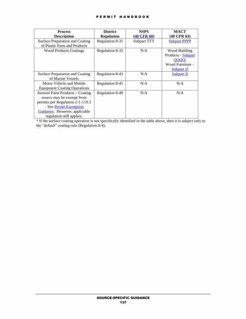
P E R M I T H A N D B O O K
SOURCE-SPECIFIC GUIDANCE
137
Process
Description
District
Regulation
NSPS
(40 CFR 60)
MACT
(40 CFR 63)
Surface Preparation and Coating
of Plastic Parts and Products
Regulation 8-31 Subpart TTT Subpart PPPP
Wood Products Coatings Regulation 8-32 N/A Wood Building
Products - Subpart
QQQQ;
Wood Furniture –
Subpart JJ
Surface Preparation and Coating
of Marine Vessels
Regulation 8-43 N/A Subpart II
Motor Vehicle and Mobile
Equipment Coating Operations
Regulation 8-45 N/A N/A
Aerosol Paint Products – Coating
source may be exempt from
permits per Regulation 2-1-119.3
– See Permit Exemption
Guidance. However, applicable
regulation still applies.
Regulation 8-49 N/A N/A
* If the surface coating operation is not specifically identified in the table above, then it is subject only to
the “default” coating rule (Regulation 8-4).

P E R M I T H A N D B O O K
SOURCE-SPECIFIC GUIDANCE
138
5.2 COATING, ADHESIVES, AND INK MANUFACTURING
by M.K. Carol Lee
October 23, 2018
Process Description
The manufacturer of coating (including adhesives) and ink involves the dispersion of a color oil or pigment
in an oil or resin, followed by the addition of an organic solvent for viscosity adjustment. Only the physical
processes of weighing, mixing, grinding, tinting, thinning, and packaging take place. These processes take
place in large mixing tanks. Detailed descriptions of coating and ink manufacturing are provided in
Chapter 6.4 (Paint and Varnish) and Chapter 6.7 (Printing Ink) of EPA AP-42.
Coating and ink manufacturing operations are generally made up a number of sources of air pollution
which store, convey, measure, and discharge its constituents. The following sources at these plants shall be
permitted:
Mixing Vats
Screening Mills
Storage Tanks (covered in Organic Liquid Storage Tank)
Completeness Determination
The following District forms should be completed and information and fees provided for coating
operations. Use the Completeness Determination Checklist to verify completeness. Use the Data Form
Guidance to ensure that the forms are completed correctly. Use the Fee Calculation Guidance to ensure
that the fees are calculated accurately.
1. Form P101-B (one for facility).
2. Form G (one per
mixing vat or screening mill)
3. Material Safety Data
Sheet for the oil, resins, and solvents used.
4. If mixing vessel
exhausts to add-on abatement device, Form
A (one per device).
5. If Health Risk
Screening is triggered, Form HRSA (one per
source).
6. Fees, calculated per
Regulation 3 (Schedule E).
Emission Calculations
The primary pollutants from coating and ink manufacturing is particulate (from the handling of pigments)
and organic compounds. AP-42, Table 6.4-1 and Table 6.7-1 provides emission factors for paint and
varnish and ink manufacturing:
Type of Process POC (lb/ton) PM10 (lb/ton)
Paint 30 20
Varnish
Bodying Oil 40
Oleoresinous 150
Alkyd 160
Acrylic 20
Printing Ink
General 120
Oils 40
Oleoresinous 150
Alkyds 160
Pigment Mixing 2
Using the AP-42 factor (see table) with the maximum, annual projected throughput (gallons/year) of
product produced will estimate the annual estimated emissions of POCs and PM10 from the proposed
coating and ink manufacturing operation.

P E R M I T H A N D B O O K
SOURCE-SPECIFIC GUIDANCE
139

P E R M I T H A N D B O O K
SOURCE-SPECIFIC GUIDANCE
140
Applicable Requirements
Rules and Regulations
Coating, ink, and adhesive manufacturing are subject to the standards of Regulation 8-35. The permit
engineer should review the proposed operations and determine any proposed mixing vats will meet the
mixing vat requirements of Regulation 8-35-301 and 305, cleaning operations for the mixing vats will
comply with the requirements of Regulation 8-35-302, and screening mills will comply with the
requirements of Regulation 8-35-304.
Best Available Control Technology (BACT)
BACT for coating and ink manufacturing is currently NOT specified in the BACT/TBACT Workbook.
Inform the BACT Coordinator of updates to the BACT/TBACT Workbook.
California Environmental Quality Act (CEQA)
Permit applications which are reviewed following the specific procedures, fixed standards and objective
measurements set forth in this chapter (5.2) are classified as ministerial and will accordingly be exempt
from CEQA review per Regulation 2-1-311. However, if BACT1, NSPS, or NESHAP requirements, then
CEQA review is also triggered because elements of discretion are required. The permit evaluator shall
follow the CEQA instructions specified in the Permit Evaluation Guidance in the permit handbook.
In addition to the above-mentioned source-specific applicable requirements, other requirements may also
be applicable depending on the facility, its application emissions, and its source location:
Offsets
Prevention of Significant Deterioration
School Notification
Risk Screening Analysis
Permit Conditions
Standardized conditions for coating and ink manufacturing operations are available from the Permit
Condition Guidance. Refer to the Evaluation Report Template Guidance to obtain the Microsoft Word
formatted permit conditions for this source category.

P E R M I T H A N D B O O K
SOURCE-SPECIFIC GUIDANCE
141
5.3 GRAPHIC ARTS PRINTING AND COATING OPERATIONS
by M.K. Carol Lee
October 23, 2018
Process Description
Any graphic arts operation that emits less than 400 pounds of VOC emissions per month on a facility-wide
basis is exempt from permitting requirements per Regulation 2-1-119.5. However, if the graphics arts
operation emits a minimum of 75 pounds but less than 400 pounds of VOC per month, it is subject to
registration requirements for small graphic arts facilities, per Regulation 8-20-408. This District’s
registration program for small graphic arts facilities is on-line at the District’s web site.
The term “graphic art” is made up of 4 basic processing of the printing industry: web offset lithography,
web letterpress, rotogravure, and flexography. These processes and their estimated emissions are described
in detail in Chapter 4.91 General Graphic Printing of AP-42 (Fifth Edition, Volume I). Additional
information including screen-printing is available from Graphic Arts, Volume III: Chapter 7, November
1996 and Preferred and Alternative Methods for Estimating Air Emissions from Printing, Packaging and
Graphic Arts Industry, May 2002.
Two or more printing presses which are less than or equal to 3,000 pounds per year VOC may be grouped
together as one source per the policy, Grouping of Coating, Adhesive or Printing Operations into a Single
Permitted Source.
Completeness Determination
The following District forms should be completed and fees provided for graphic arts operations. Use the
Completeness Determination Checklist to verify completeness. Use the Data Form Guidance to ensure that
the forms are completed correctly. Use the Fee Calculation Guidance to ensure that the fees are calculated
accurately.
1. Form 101-B (one for facility).
2. Form S (one per
source).
3. Form SS (one per
source or facility).
4. Material Safety Data
Sheet for the inks and press washes used, if
it is a mixture of compounds.
5. If graphic arts
operation exhausts to add-on abatement
device, Form A (one per device).
6. If Health Risk
Screening is triggered, Form HRSA (one per
source).
7. Fees, calculated per
Regulation 3 (Schedule E).
Emission Calculations
Using the material balance method, for VOC-containing materials, the amount of pollutant emitted is often
assumed to be 100 percent of the amount of pollutant contained in the material as applied, unless a control
device is used to remove or destroy the VOC in the exhaust stream. In addition, for lithographic printing
operations, a retention factor of 95% is used for lithographic inks, per Regulation 8-20-605. The 95%
retention factor equates into a 5% release factor and was established. To estimate the VOC emissions from
vented operations where a VOC control device is present, it is necessary to estimate the efficiency of both
the capture (exhaust) system and the control device.
Applicable Requirements
In general, graphic arts operations are subject to the operating standards of Regulation 8-20, unless the
facility meets the definition of a Small User, per Regulation 8-20-110. The District permit evaluator should
review the material to ensure that the source meets applicable operating standards or else request such
information from the applicant.
Best Available Control Technology (BACT)
BACT for coating sources is specified in the BACT/TBACT Workbook. A procedure has been developed
for BACT1 review of adding an automatic blanket wash system to a lithographic operation. The following
are applicable BACT requirements for:

P E R M I T H A N D B O O K
SOURCE-SPECIFIC GUIDANCE
142
Graphic Arts Printing and Coating Operations
- Flexographic Printing Line
- Lithographic Offset Printing - Heatset
- Lithographic Offset Printing - Non-Heatset
- Rotogravure Printing - Publication and
Packaging
- Screen Printing and Drying
Inform the BACT Coordinator of updates to the BACT/TBACT Workbook.
California Environmental Quality Act (CEQA)
Permit applications which are reviewed following the specific procedures, fixed standards and objective
measurements set forth in this chapter (5.3) are classified as ministerial and will accordingly be exempt
from CEQA review per Regulation 2-1-311.
In addition to the above-mentioned source-specific applicable requirements, other requirements may also
be applicable depending on the facility, its application emissions, and its source location:
Offsets
Prevention of Significant Deterioration
School Notification
Risk Screening Analysis
Permit Conditions
Standardized conditions for graphic arts printing and coating operations are available from the Permit
Condition Guidance. Refer to the Evaluation Report Template Guidance to obtain the Microsoft Word
formatted permit conditions for this source category.

P E R M I T H A N D B O O K
SOURCE-SPECIFIC GUIDANCE
143
6.1 COLD SOLVENT CLEANING
by M.K. Carol Lee
October 23, 2018
Process Description
A Cold (Non-boiling) Cleaner is defined in Regulation 8-16-204 as any solvent cleaner, excluding
conveyorized solvent cleaners and vapor solvent cleaners, including, but not limited to, spray sinks, spray
booths, spray gun cleaners and batch-loaded dip tanks. Any cold cleaner, which uses 20 or more gallons
per year of solvent (>50 g/l or 0.42 lb/gal VOC) is subject to permitting requirements, per Regulation 2-1-
118.4 and Regulation 2-1-118.7. Additional background information is available from Chapter 4.6, Solvent
Degreasing, of AP-42 (Fifth Edition, Volume I).
Spray gun cleaners that are associated with coating sources (i.e., cleaning of coating application equipment
or cleaning of surfaces prior to their coating) are to be permitted, as part of a coating operation and this
permit chapter does not apply -- See Spray Booths & Spray Guns.
Completeness Determination
The following District forms should be completed and fees provided for cold cleaner(s). Use the
Completeness Determination Checklist to verify completeness. Use the Data Form Guidance to ensure that
the forms are completed correctly. Use the Fee Calculation Guidance to ensure that the fees are calculated
accurately.
1. Form 101-B (one for facility).
2. Form S (one per
source).
3. Form SC (one per
source).
4. Material Safety Data
Sheet for each solvent used, if it is a mixture
of compounds.
5. If cold cleaner
exhausts into add-on abatement device, Form A
(one per device).
6. If Health Risk
Screening is triggered, Form HRSA (one per
source).
7. Fees, calculated per
Regulation 3 (Schedule E).
Emission Calculations
Net organic solvents used in cold cleaners are assumed to be 100 percent volatile and emitted into the
atmosphere. Annual emissions are calculated by multiplying the annual net solvent usage by the density of
the organic solvent.
Applicable Requirements
District Rules and Regulations
In general, cold cleaners are subject to the operating standards of Regulation 8-16-303. All facilities that
use cold cleaners for repair and maintenance operations (defined in Regulation 8-16-233) are required to
use aqueous cleaners (VOC < 50 grams/liter) or methylated siloxanes (VMS), unless exempt per
Regulation 8-16-123. Repair and maintenance operations typically include but are not limited to vehicle
and other machine repair shops. If cold cleaners use aqueous cleaners then they are exempt from
permitting requirements per Regulation 2-1-118.7. However, use of methylated siloxanes is NOT exempt
from permit requirements. Cold cleaners using methylated siloxanes must be permitted. The District
permit evaluator should review the applicant’s SC Form to ensure that the source meets applicable
operating standards or else request such information from the applicant.
Best Available Control Technology (BACT)
BACT for Cold Cleaners is specified in the BACT/TBACT Workbook. The following are applicable
BACT requirements for:
Cold Solvent Cleaning
- Degreaser - Cold Solvent Tank
Inform the BACT Coordinator of updates to the BACT/TBACT Workbook.
P E R M I T H A N D B O O K
SOURCE-SPECIFIC GUIDANCE
144
California Environmental Quality Act (CEQA)
Permit applications which are reviewed following the specific procedures, fixed standards and objective
measurements set forth in this chapter (6.1) are classified as ministerial and will accordingly be exempt
from CEQA review per Regulation 2-1-311.
NESHAP may apply for those cold cleaners using halogenated cleaning solvents specified in Regulation 8-
16-216 at a total concentration of 5 percent or more by weight.
In addition to the above-mentioned source-specific applicable requirements, other requirements may also
be applicable depending on the facility, its application emissions, and its source location:
Offsets
Prevention of Significant Deterioration
School Notification
Risk Screening Analysis
Permit Conditions
Standardized conditions for cold cleaners are available from the Permit Condition Guidance. Refer to the
Evaluation Report Template Guidance to obtain the Microsoft Word formatted permit conditions for this
source category.

P E R M I T H A N D B O O K
SOURCE-SPECIFIC GUIDANCE
145
6.2 VAPOR SOLVENT & CONVEYORIZED SOLVENT CLEANING
by M.K. Carol Lee
October 23, 2018
Process Description
A vapor solvent cleaner is defined in Regulation 8-16-228 as any solvent cleaner which cleans through the
condensation of hot solvent vapor on colder parts and boils liquid solvent producing solvent vapor, while
conveyorized solvent cleaner is defined in Regulation 8-16-207 as any continuously loaded, conveyorized
cold or vapor solvent cleaner. Additional background information is available from Chapter 4.6, Solvent
Degreasing, of AP-42 (Fifth Edition, Volume I).
Completeness Determination
The following District forms should be completed and fees provided for vapor solvent and conveyorized
solvent cleaner(s). Use the Completeness Determination Checklist to verify completeness.
Use the Data Form Guidance to ensure that the forms are completed correctly. Use the Fee Calculation
Guidance to ensure that the fees are calculated accurately.
1. Form 101-B (one for facility).
2. Form S (one per
source).
3. Form SC (one per
source).
4. Material Safety Data
Sheet for each solvent used, if it is a mixture
of compounds.
5. If cleaner exhausts
into add-on abatement device, Form A (one per
device).
6. If Health Risk
Screening is triggered, Form HRSA (one per
source).
7. Fees, calculated per
Regulation 3 (Schedule E).
Emission Calculations
Net organic solvents used in the solvent cleaners are assumed to be 100 percent volatile and emitted into
the atmosphere. Annual emissions are calculated by multiplying the annual net solvent usage by the density
of the organic solvent.
Applicable Requirements
District Rules and Regulations
In general, vapor solvent cleaners are subject to the operating standards of Regulation 8-16-301, while
conveyorized solvent cleaners are subject to the operating standards of Regulation 8-16-302. The District
permit evaluator should review the applicant’s SC Form to ensure that the source meets applicable
operating standards or else request such information from the applicant.
Best Available Control Technology (BACT)
BACT for vapor and conveyorized solvent cleaners is specified in the BACT/TBACT Workbook. The
following are applicable BACT requirements for:
Vapor Solvent Cleaning
- Degreaser - Film Cleaning Machine
- Degreaser - Solvent Spray Booth
- Degreaser - Vapor, Conveyorized
- Degreaser - Vapor, Open Top
Inform the BACT Coordinator of updates to the BACT/TBACT Workbook.
California Environmental Quality Act (CEQA)
Permit applications which are reviewed following the specific procedures, fixed standards and objective
measurements set forth in this chapter (6.2) are classified as ministerial and will accordingly be exempt
from CEQA review per Regulation 2-1-311.
NESHAP may apply for those cleaners using halogenated cleaning solvents specified in Regulation 8-16-
216 at a total concentration of 5 percent or more by weight.

P E R M I T H A N D B O O K
SOURCE-SPECIFIC GUIDANCE
146

P E R M I T H A N D B O O K
SOURCE-SPECIFIC GUIDANCE
147
In addition to the above-mentioned source-specific applicable requirements, other requirements may also
be applicable depending on the facility, its application emissions, and its source location:
Offsets
Prevention of Significant Deterioration
School Notification
Risk Screening Analysis
Permit Conditions
Standardized conditions for vapor and conveyorized solvent cleaners are available from the Permit
Condition Guidance. Refer to the Evaluation Report Template Guidance to obtain the Microsoft Word
formatted permit conditions for this source category.

P E R M I T H A N D B O O K
SOURCE-SPECIFIC GUIDANCE
148
6.3 WIPE CLEANING OPERATION
by M.K. Carol Lee
October 23, 2018
Process Description
Wipe Cleaning is defined in Regulation 8-16-232 as that method of cleaning which utilizes a material such
as a rag wetted with a solvent, coupled with a physical rubbing process to remove contaminants from
surfaces. Any wipe cleaning operation, which uses 20 or more gallons per year of solvent and having
emissions greater than 150 pounds per year, is subject to permitting requirements, per Regulation 2-1-
118.9. Wipe cleaning operations may be combined together as one facility-wide source or other convenient
groupings per Regulation 2-1-401.4.
Wipe cleaning operations that are associated with coating sources (i.e., cleaning of coating application
equipment or cleaning of surfaces prior to their coating) are to be permitted, as part of a coating operation
and this permit chapter does not apply -- See Spray Booths & Spray Guns.
Completeness Determination
The following District forms should be completed and fees provided for the wipe cleaning operation. Use
the Completeness Determination Checklist to verify completeness. Use the Data Form Guidance to ensure
that the forms are completed correctly. Use the Fee Calculation Guidance to ensure that the fees are
calculated accurately.
1. Form 101-B (one for facility).
2. Form S (one per
source).
3. Form SC (one per
source).
4. Material Safety Data
Sheet for each solvent used, if it is a mixture
of compounds.
5. If wipe cleaning
operation exhausts into add-on abatement device,
Form A (one per device).
6. If Health Risk
Screening is triggered, Form HRSA (one per
source).
7. Fees, calculated per
Regulation 3 (Schedule E).
Emission Calculations
Any organic solvents used for wipe cleaning are assumed to be 100 percent volatile and emitted into the
atmosphere. Annual emissions are calculated by multiplying the annual gross solvent usage by the density
of the organic solvent.
Applicable Requirements
District Rules and Regulations
Wipe cleaning operations are subject to the storage and disposal requirements of Regulation 8-1-320, 321,
and 322 and the recordkeeping requirements of Regulation 8-16-501 and Regulation 8-4-501. In addition,
each wipe cleaning operation is subject to either 1)Regulation 8-4-302.1 (< 5 TPY/source) OR 2)
Regulation 8-4-302.2 (85% overall control) AND 3) the evaporative loss minimization requirements of
Regulation 8-4-312. Moreover, wipe cleaning operations for 1) the cleaning of surfaces prior to Regulation
8-4 coating operations OR 2) further treatment, sale, or intended use are subject to the VOC standards of
Regulation 8-4-313, unless specifically exempt by Regulation 8-4-116. The District permit evaluator
should ensure that the applicant is exempt per Regulation 8-4-116 prior to approval of any wipe cleaning
permit application.
Best Available Control Technology (BACT)
BACT for Wipe Cleaning is specified in the BACT/TBACT Workbook. The following are applicable
BACT requirements for:
Wipe Cleaning
- Wipe Cleaning Operation
- Solvent Reclamation
Inform the BACT Coordinator of updates to the BACT/TBACT Workbook.
P E R M I T H A N D B O O K
SOURCE-SPECIFIC GUIDANCE
149
California Environmental Quality Act (CEQA)
Permit applications which are reviewed following the specific procedures, fixed standards and objective
measurements set forth in this chapter (6.3) are classified as ministerial and will accordingly be exempt
from CEQA review per Regulation 2-1-311.
In addition to the above-mentioned source-specific applicable requirements, other requirements may also
be applicable depending on the facility, its application emissions, and its source location:
Offsets
Prevention of Significant Deterioration
School Notification
Risk Screening Analysis
Permit Conditions
Standardized conditions for wipe cleaning operations are available from the Permit Condition Guidance.
Refer to the Evaluation Report Template Guidance to obtain the Microsoft Word formatted permit
conditions for this source category.

P E R M I T H A N D B O O K
SOURCE-SPECIFIC GUIDANCE
150
7.2 ELECTRONIC ASSEMBLY AND WAVE SOLDERING OPERATONS
by M.K. Carol Lee
October 23, 2018
Process Description
Electronic Assembly/Soldering is where electronic components are assembled and soldered onto printed
circuit boards. The process steps include hand assembly, wave soldering, solder paste application with
reflow oven, and solvent cleaning. Hand assembly is where components are manually assembled and
soldered onto printed circuit boards. The process steps include flux application and hand soldering. Wave
soldering is where components are soldered onto the printed circuit board by a wave soldering machine.
The solder paste application with reflow oven involves the application of solder paste to pad locations on
the printed circuit board through a stencil. Components are then surface mounted onto the printed circuit
board with a pick and place machine. After inspection, the surface mounted components are joined to the
printed circuit board inside the reflow oven. The potential of pollutants into the atmosphere are organic
emissions from the use of solvents and solvent-containing materials.
The following equipment is typically exempt from permitting requirements:
Description of Equipment Permit Exemption
Any flux application, hand soldering, wave soldering, solder paste
application which meets the criteria of Regulation 2-1-103.
2-1-103
Any reflow oven used in conjunction with a solder paste application which
meets the criteria of Regulation 2-1-103.
2-1-119.4.
This permit handbook chapter describes the permitting requirements and procedures for those electronic
assembly and wave soldering operations which are not exempt from permitting requirements per
Regulation 2-1-103. The potential of pollutants into the atmosphere are organic emissions from the use of
solvents and solvent-containing materials.
Permitting of solvent cleaning is covered by other Permit Handbook Chapters such as Wipe Cleaning (6.3)
and Vapor Solvent Cleaning (6.2).
Completeness Determination
The following District forms should be completed and fees provided for disc lubers. Use the Completeness
Determination Checklist to verify completeness. Use the Data Form Guidance to ensure that the forms are
completed correctly. Use the Fee Calculation Guidance to ensure that the fees are calculated accurately.
1. Form 101-B (one for facility).
2. Form S (one per
source).
3. Material Safety Data
Sheet for each solvent-containing material
used, if it is a mixture of compounds.
4. If the electronic
assembly and save soldering operations exhausts
into add-on abatement device, Form A (one per
device).
5. If Health Risk
Screening is triggered, Form HRSA (one per
source).
6. Fees, calculated per
Regulation 3 (Schedule E).
Emission Calculations
Using the material balance method, for VOC-containing materials, the amount of pollutant emitted is often
assumed to be 100 percent of the amount of pollutant contained in the material.
E lb POC/yr = [X gal flux/yr] x[Y lb flux/gal flux] x [Z lb POC/lb flux],
where,
E = Emissions of POC (lb/yr)
X = Maximum annual quantity of flux used (gal/yr)
Y = density of flux (lb/gal)
Z = POC wt fraction of flux (lb/lb)

P E R M I T H A N D B O O K
SOURCE-SPECIFIC GUIDANCE
151

P E R M I T H A N D B O O K
SOURCE-SPECIFIC GUIDANCE
152
Applicable Requirements
District Rules and Regulations
In general, electronic assembly and save soldering operations are subject to the operating standards of
Regulation 8-1 and 8-4. The standards require that closed containers be used for disposal of cloth or paper
impregnated with organic compounds; that closed containers be used for storage of organic compounds;
and that evaporation of organic compounds during the cleaning of spray equipment be minimized. In
addition, emissions are limited to 5 TPY per flux application and wave soldering operation.
Best Available Control Technology (BACT)
BACT for flexible and rigid disc manufacturing is specified in the BACT/TBACT Workbook. The
following are applicable BACT requirements for:
Electronic Assembly & Wave Soldering Operations
- Wave Solder Operation - Flux Application and Finger Cleaning
Inform the BACT Coordinator of updates to the BACT/TBACT Workbook.
California Environmental Quality Act (CEQA)
Permit applications which are reviewed following the specific procedures, fixed standards and objective
measurements set forth in this chapter (7.3) are classified as ministerial and will accordingly be exempt
from CEQA review per Regulation 2-1-311.
In addition to the above-mentioned source-specific applicable requirements, other requirements may also
be applicable depending on the facility, its application emissions, and its source location:
Offsets
Prevention of Significant Deterioration
School Notification
Risk Screening Analysis
Permit Conditions
Standardized conditions for electronic assembly and wave soldering operations are available from the
Permit Condition Guidance. Refer to the Evaluation Report Template Guidance to obtain the Microsoft
Word formatted permit conditions for this source category.

SOURCE-SPECIFIC GUIDANCE
153
7.3 FLEXIBLE AND RIGID DISC MANUFACTURING
by M.K. Carol Lee
October 23, 2018
Process Description
The manufacturer of flexible and rigid discs includes the following operations: disc lubers and disc
polishing. Disc lubers are used to coat magnetic memory discs with a thin layer of fluorocarbon polymer
lubricant. The solvent is typically a non-precursor organic compound. There are three types of disc lubers:
gravity flow, dip, and spray. Gravity flow disc lubers operate in the following manner:
1. a rack of discs is loaded into a chamber
2. a lubricant/solvent mixture is pumped into the chamber, submerging the discs
3. the lubricant/solvent mixture is allowed to drain slowly, leaving a thin layer of lubricant on the
discs
4. the discs are removed from the chamber
Dip lubers manually coat disc(s) in a bath of lubricant/solvent mixture in a dipping (and draining)
operation. Spray lubers spray the discs with lubricant/solvent mixture in an enclosed chamber.
Disc polishing /texturing is a technique using a physical rubbing process with an organic solvent on the
surface of flexible or rigid magnetic data storage disc for the purpose of removing contaminants or
oxidation or for increasing surface smoothness, resolution or gloss. Solvent cleaning devices using
immersion or agitation in solvent vapors are not considered disc polishing/texturing, but solvent cleaning
subject to Regulation 8-16 and Vapor and Conveyorized Solvent Cleaning permit handbook chapter (6.3).
Completeness Determination
The following District forms should be completed and fees provided for disc lubers. Use the Completeness
Determination Checklist to verify completeness. Use the Data Form Guidance to ensure that the forms are
completed correctly. Use the Fee Calculation Guidance to ensure that the fees are calculated accurately.
1. Form 101-B (one for facility).
2. Form S (one per
source).
3. Material Safety Data
Sheet for each solvent used, if it is a mixture
of compounds.
4. If the disc luber
exhausts into add-on abatement device, Form A
(one per device).
5. If Health Risk
Screening is triggered, Form HRSA (one per
source).
6. Fees, calculated per
Regulation 3 (Schedule E).
Emission Calculations
Net organic solvents used in the solvent cleaners are assumed to be 100 percent volatile and emitted into
the atmosphere. Annual emissions are calculated by multiplying the annual net solvent usage by the density
of the organic solvent.
Applicable Requirements
District Rules and Regulations
In general, disc lubers are subject to the operating standards of Regulation 8-1. The standards require that
closed containers be used for disposal of cloth or paper impregnated with organic compounds; that closed
containers be used for storage of organic compounds; and that evaporation of organic compounds during
the cleaning of spray equipment be minimized.
Specifically, disc lubers (also known as disc coaters) and disc polishing operations are subject to the
operating standards of Regulation 8-38. The permit engineer should evaluate the permit application for
compliance with the operating standards of Regulation 8-38.

SOURCE-SPECIFIC GUIDANCE
154
Best Available Control Technology (BACT)
BACT for flexible and rigid disc manufacturing is specified in the BACT/TBACT Workbook. The
following are applicable BACT requirements for:
Magnetic Media Manufacturing - Disc Coating, Lubricant
- Dip Luber
- Gravity Drop (Drain) Luber
- Spray Luber
Magnetic Media Manufacturing - Disc Polishing/Texturing
- <22 lb/day Emissions (Uncontrolled)
- >=22 lb/day Emissions (Uncontrolled)
Inform the BACT Coordinator of updates to the BACT/TBACT Workbook.
California Environmental Quality Act (CEQA)
Permit applications which are reviewed following the specific procedures, fixed standards and objective
measurements set forth in this chapter (7.3) are classified as ministerial and will accordingly be exempt
from CEQA review per Regulation 2-1-311.
In addition to the above-mentioned source-specific applicable requirements, other requirements may also
be applicable depending on the facility, its application emissions, and its source location:
Offsets
Prevention of Significant Deterioration
School Notification
Risk Screening Analysis
Permit Conditions
Standardized conditions for disc lubers are available from the Permit Condition Guidance. Refer to the
Evaluation Report Template Guidance to obtain the Microsoft Word formatted permit conditions for this
source category.

P E R M I T H A N D B O O K
SOURCE-SPECIFIC GUIDANCE
155
7.4 SEMICONDUCTOR FABRICATION
by M.K. Carol Lee
October 23, 2018
Process Description
Semiconductor manufacturing refers to the series of manufacturing processes, which produce packaged
integrated circuits (ICs). Most packaged ICs are assembled onto printed circuit boards (PCBs) by a
separate manufacturer. However, some packaged ICs, such as microprocessor upgrades and memory
modules, are used without pre-assembly onto a circuit board. PCB assembly is the subject of a separate
Permit Handbook chapter. A thorough description of the semiconductor manufacturing process is available
in Chapter 1 of Revision 2 of this permit handbook chapter.
Completeness Determination
The following District forms should be completed and fees provided for semiconductor fabrication (FAB).
Use the Completeness Determination Checklist to verify completeness. Use the Data Form Guidance to
ensure that the forms are completed correctly. . Use the Fee Calculation Guidance to ensure that the fees
are calculated accurately.
1. Form 101-B (one for facility).
2. Form FF (one per source).
3. Material Safety Data Sheet for each solvent
mixture, photoresist coating, stripper, and
developer identified in Form FF.
4. If fab area equipment exhausts into add-on
abatement device, Form A (one per device).
5. If Health Risk Screening is triggered, Form
HRSA (one per source).
6. Fees, calculated per Regulation 3 (Schedule
H).
Emission Calculations
Emission factors are typically used in calculating emissions from semiconductor fabrication operations.
For any material applied at a wafer coating applicator, including coatings, developers, dispensed cleanup
solvents, and processing solvents, the emission factor is 90% of the total solvent content of material. For
solvent station chemicals used at solvent sinks or other solvent stations, the emission factor of 30% of the
total solvent content of all chemicals is used. For wipe cleaning operations, the emission factor of 100% of
the total solvent content of the solvent is used. A thorough background explanation of these factors is
provided in Section 3 of Revision 2 of this permit handbook chapter.
Applicable Requirements
District Rules and Regulations
Semiconductor manufacturing operations are subject to Regulation 8-30: Semiconductor Manufacturing
Operations. The permit evaluator shall ensure the applicant complies with all sections of the rule that
apply:
If Use Then Subject to
Solvent –based developers < 24
gals/month of solvent-based maskant
and developer
Regulation 8-30-402
Solvent-based developers > 24
gals/month of solvent-based maskant
and developer
Regulation 8-30-302
Solvent Sinks Regulation 8-30-304
Solvent Spray Stations Regulation 8-30-305
Solvent Vapor Stations Regulation 8-30-306
Wipe Cleaning Operations Regulation 8-30-307
Best Available Control Technology (BACT)
BACT for semiconductor fabrication operations is specified in the BACT/TBACT Workbook. The
following are applicable BACT requirements for:
Semiconductor Manufacturing Operations

P E R M I T H A N D B O O K
SOURCE-SPECIFIC GUIDANCE
156
- Semiconductor Fab - Photoresist Operations
- Semiconductor Fab - Solvent Cleaning Stations
- Semiconductor Fab - Siliconizing Reactors,Furnace Chambers, Vapor Deposition
Inform the BACT Coordinator of updates to the BACT/TBACT Workbook.
California Environmental Quality Act (CEQA)
Permit applications which are reviewed following the specific procedures, fixed standards and objective
measurements set forth in this chapter (7.4) are classified as ministerial and will accordingly be exempt
from CEQA review per Regulation 2-1-311.
NESHAP requirements may apply for a semiconductor manufacturing facility, which emits or has the
potential to emit any single HAP at a rate of 10 tons per year or more or any combination of HAP at a rate
of 25 tons per year or more. In general, semiconductors facilities in the Bay Area are not subject to these
NESHAP requirements, because after controls their HAP emissions are well below the NESHAP trigger
levels. However, the permit evaluator should still review the applicant’s HAP emissions to ensure that
NESHAP requirements are not triggered.
In addition to the above-mentioned source-specific applicable requirements, other requirements may also
be applicable depending on the facility, its application emissions, and its source location:
Offsets
Prevention of Significant Deterioration
School Notification
Risk Screening Analysis
Permit Conditions
Standardized conditions for semiconductor fabrication areas are available from the Permit Condition
Guidance. Refer to the Evaluation Report Template Guidance to obtain the Microsoft Word formatted
permit conditions for this source category.

P E R M I T H A N D B O O K
SOURCE-SPECIFIC GUIDANCE
157
8.2 WASTEWATER TREATMENT FACILITIES
by M.K. Carol Lee
October 23, 2018
Process Description
EPA’s Chapter 4.3 (Waste Water Collection, Treatment And Storage) of AP-42 provides information
regarding the wastewater collection, treatment, and storage. This permit handbook chapter covers the
permitting of typical unit operations at publicly owned treatment works (POTW) facilities. These plants
treat wastewater from sanitary and storm sewer systems prior to discharge into the Bay or reuse as
reclaimed water. Typical POTW sources may be defined as a combination of the liquid or water carried
wastes removed from residences, institutions, and commercial and industrial establishments, together with
groundwater, surface water, and storm water runoffs.
Each of the process categories at the wastewater treatment facilities should be permitted as a separate
source “grouping” with an assigned a source number and process code (for Data Form G entry) as
indicated in the following table. The material code for wastewater or municipal sewage is 562 and the
“usage unit” is million gallons (for Data Form G entry).
Process/Source
Description
Definition of Process/Source
Description
Examples of Equipment
Included in Source Description
Process
Code
Preliminary Treatment
(use default source
number, S-110, if
available)
Preliminary treatment to screen
out, grind up, or separate debris
is the first step in wastewater
treatment. Sticks, rags, large
food particles, sand, gravel, toys,
etc., are removed at this stage to
protect the pumping and other
equipment in the treatment plant.
Treatment equipment such as bar
screens, comminutors (a large
version of a garbage disposal), and
grit chambers are used as the
wastewater first enters a treatment
plant. The collected debris is
usually disposed of in a landfill.
7210
Primary Treatment
(use default source
number, S-120, if
available)
In primary treatment systems,
physical operations remove
floatable and settleable solids.
Oil-water separators, primary
clarifiers, and primary treatment
tanks.
7220
Flow Equalization
(use default source
number, S-130, if
available)
Flow rate equalization results in
a more uniform effluent quality
in downstream settling units,
such as clarifiers.
Equalization basins are used to
reduce fluctuations in the
wastewater flow rate and organic
content before the waste is sent to
downstream treatment processes.
7230
Secondary Treatment
(use default source
number, S-140, if
available)
In secondary treatment systems,
biological and chemical
processes remove most of the
organic matter in the wastewater.
Biological waste treatment in
tanks and oxidation ponds.
7240
Secondary Clarifiers
(use default source
number, S-150, if
available)
Used in secondary treatment
systems to settle and remove
settleable or suspended solids.
Secondary clarifier. 7250
Tertiary Treatment
(use default source
number, S-160, if
available)
In tertiary treatment systems,
additional processes remove
constituents not taken out by
secondary treatment.
Advanced treatment is necessary in
some treatment systems to remove
nutrients from wastewater.
Chemicals are sometimes added
during the treatment process to
help settle out or strip out
phosphorus or nitrogen. Some
examples of nutrient removal
systems include coagulant addition
for phosphorus removal and air
7260

P E R M I T H A N D B O O K
SOURCE-SPECIFIC GUIDANCE
158
Process/Source
Description
Definition of Process/Source
Description
Examples of Equipment
Included in Source Description
Process
Code
stripping for ammonia removal.
Nitrification Basins
Disinfection
(use default source
number, S-170, if
available)
Disinfection focuses on removal
of disease-causing organisms
from wastewater. Treated
wastewater can be disinfected by
adding chlorine or by using
ultraviolet light. High levels of
chlorine may be harmful to
aquatic life in receiving streams.
Treatment systems often add a
chlorine-neutralizing chemical to
the treated wastewater before
stream discharge.
Chlorine Contact Tanks and
De-chlorination.
7270
Sludge Handling
Processes
(use default source
number, S-180, if
available)
Sludges are generated through
the sewage treatment process.
Primary sludges, material that
settles out during primary
treatment, often have a strong
odor and require treatment prior
to disposal. Secondary sludges
are the extra microorganisms
from the biological treatment
processes. The goals of sludge
treatment are to stabilize the
sludge and reduce odors, remove
some of the water and reduce
volume, decompose some of the
organic matter and reduce
volume, kill disease-causing
organisms and disinfect the
sludge.
Water can be removed from sludge
by using sand drying beds,
vacuum filters, filter presses, and
centrifuges.
7280
Digesters
(use default source
number, S-190, if
available)
Aerobic and anaerobic digestion
are used to decompose organic
matter to reduce sludge volume
and its odors.
Aerobic and anaerobic digesters. 7290
Storage vessels, which contain hydrocarbon condensate, require a permit if the vessel is greater than 260
gallons in capacity, per Regulation 2-1-123.1 and contain an organic layer which is greater than 1 weight
percent VOC per Regulation 2-1-123.6. The permitting of these storage tanks is covered in the permit
handbook for Organic Liquid Storage Tanks.

P E R M I T H A N D B O O K
SOURCE-SPECIFIC GUIDANCE
159
Completeness Determination
The following District forms should be completed and fees provided for the wastewater treatment facilities.
Use the Completeness Determination Checklist to verify completeness. Use the Data Form Guidance to
ensure that the forms are completed correctly. Use the Fee Calculation Guidance to ensure that the fees are
calculated accurately.
1. Form 101-B (one for facility).
2. Form G (one per source). See the Process
Description section for Process Code,
Material Code, and Usage Unit.
3. Process Diagram and Map.
4. If any source exhausts into an add-on
abatement device, Form A (one per device).
5. If Health Risk Screening is triggered, Form
HRSA (one per source).
6. Fees, calculated per Regulation 3 (Schedule
G1) for Industrial and Municipal
Wastewater Treatment Facilities (except
petroleum refineries) and (Schedule G2) for
Wastewater Treatment at Petroleum
Refineries.
Emission Calculations
In general, POTWs are large facilities with processes and flow characteristics, which may differ greatly
from facility to facility. There are no emission factors, which can be used without some measure of
uncertainty. There are a number of emission methods, which can be used depending on the operation and
other parameters. These emission estimation methods are presented as follows:
A) Mass Balance: Emissions are calculated based on liquid concentrations from the proposed source
(influent and effluent concentrations).
B) Refined Mass Balance: Emissions are calculated based on liquid concentrations, while
accounting for competing removal mechanisms, such as biodegradation and adsorption.
C) Fate Emissions Estimation Models (BAAT's BASTE Model): The Bay Area Air Toxics
(BAAT) Group's BASTE model can be modified to include the top 95 percent of the reactive
organic gases (ROGs). This model estimates pathway losses (volatilization, sorption, and
biodegradation) based on liquid-phase concentration measurements coupled with information
related to wastewater flow (flow rate, depth of flow, etc), fluid characteristics (temperature,
suspended solids, etc), contaminant properties, and physical properties of the unit operations.
D) Tracer Studies: This method utilizes a steady dosing of a tracer compound into the influent of the
treatment process and simultaneous analysis for the tracer in the effluent and off-gases. The
emissions for other compounds can be calculated based on known physical constants, such as
gas/water partition and biodegradation rate.
E) Source Tests: This method includes stack testing, for confined sources or combustion sources,
and surface isolation flux chambers for area sources.
F) Industry-wide Emission Factors: This method uses conservative values developed from a wide
range of POTWs to determine air emission rates.
G) 80th Percentile Emission Factors: Although there are no universal emission factors for POTWs
which can be used without some uncertainty, it is possible to use certain average emission factors
developed by the Bay Area Air Toxics (BAAT) POTW Group. The 80th percentile method allows
certain POTWs to calculate air emissions from liquid processes within an 80% confidence
interval. Emission Factors are entered for source S-100 (Municipal Wastewater Treatment Plant)
instead of individual sources. These emission factors are presented in the following table.

P E R M I T H A N D B O O K
SOURCE-SPECIFIC GUIDANCE
160
80th Percentile Emission Factors
POTW Liquid Processes
Emission Factor
Compound (lb/yr per MM gal/day)
Methylene Chloride 95
Chloroform 40
1,1,1-TCA 110
Benzene 3.7
TCE 11
Toluene 28
Tetrachloroethylene 37
Xylenes 33
1,4-Dichlorobenzene 5
H) Indirect Measurement: This method uses indirect air measurement techniques such as
transection, fenceline, and/or ambient air monitoring to calculate the sources of air emission.
Alternatively, the EPA’s Measurement Policy Group recommends the use of the WATER9 software
program. The SIMS program, referred to in Section 4.3 of EPA’s AP-42, was removed from the CHIEF
web site in August 2000.
Applicable Requirements
District Rules and Regulations
Wastewater collection and separation systems that handle liquid organic compounds from industrial
processes are subject to the standards of Regulation 8-8. However, Regulation 8-8-115 specificially
exempts publicly owned municipal waste water handling facilities from the standards of Regulation 8-8.
The wastewater treatment facility may be subject to Regulation 7 (Odorous Substances), if it is considered
a potential source of odors. Abatement may be warranted if the uncontrolled source has demonstrated
odors in the past or has the potential to be odorous.
Best Available Control Technology (BACT)
The following are applicable BACT requirements for:
Sewage Treatment Facilities Works (POTWs)
Sewage Treatment Plants
- Headworks and Primary Treatment
- Conventional Air Activated Sludge
- High Purity Oxygen Activated Sludge
- Secondary Clarifiers and Tertiary Treatment
- Solids Handling Equipment
- Digesters and Sludge Holding Tanks
Inform the BACT Coordinator of updates to the BACT/TBACT Workbook.
NSPS
Municipal waste incinerators at sewage treatment facilities may be subject to the NSPS, Subpart O:
Standards of Performance for VOC Emissions for Sewage Treatment Facilities. In addition, oil-water
separators at a petroleum refinery may be subject to the NSPS, Subpart QQQ: Standards of Performance for
VOC Emissions From Petroleum Refinery Wastewater Systems. The permit engineer should review the
proposed application to ensure that any proposed incinerator or oil-water separator is either exempt from
the NSPS or complies with the NSPS.

P E R M I T H A N D B O O K
SOURCE-SPECIFIC GUIDANCE
161
California Environmental Quality Act (CEQA)
Permit applications which are reviewed following the specific procedures, fixed standards and objective
measurements set forth in this chapter (8.2) are classified as ministerial and will accordingly be exempt
from CEQA review per Regulation 2-1-311.
In addition to the above-mentioned source-specific applicable requirements, other requirements may also
be applicable depending on the facility, its application emissions, and its source location:
Offsets
Prevention of Significant Deterioration
School Notification
Risk Screening Analysis
Permit Conditions
Standardized conditions for sewage treatment facilities are available from the Permit Condition Guidance.
Refer to the Evaluation Report Template Guidance to obtain the Microsoft Word formatted permit
conditions for this source category.

P E R M I T H A N D B O O K
SOURCE-SPECIFIC GUIDANCE
162
9.1 AIRSTRIPPING
by M.K. Carol Lee
October 23, 2018
Process Description
This chapter covers the permitting of air stripping operations. Air stripping involves the mass transfer of
volatile contaminants from water to air. For ground water remediation, this process is typically conducted
in a packed tower or an aeration tank. The typical packed tower air stripper includes a spray nozzle at the
top of the tower to distribute contaminated water over the packing in the column, a fan to force air
countercurrent to the water flow, and a sump at the bottom of the tower to collect decontaminated water.
Auxiliary equipment that can be added to the basic air stripper includes an air heater to improve removal
efficiencies; automated control systems with sump level switches and safety features, such as differential
pressure monitors, high sump level switches, and explosion-proof components; and air emission control
and treatment systems, such as activated carbon units, catalytic oxidizers, or thermal oxidizers. Packed
tower air strippers are installed either as permanent installations on concrete pads or on a skid or a trailer.
Completeness Determination
The following District forms should be completed and fees provided for the air stripping operations. Use
the Completeness Determination Checklist to verify completeness. Use the Data Form Guidance to ensure
that the forms are completed correctly. Use the Fee Calculation Guidance to ensure that the fees are
calculated accurately.
1. Form 101-B (one for facility).
2. Form G (one per source). Process code is
5040 for air stripping/DAF processing, 7155
for contaminated ground water stripping,
and 7353 for sub-slab
depressurization/mitigation/venting systems.
Material code is 502, and usage unit is
thousand gallons.
3. Form A (one per abatement device).
4. If abatement device burns fuel (i.e., thermal
oxidizer), then Form C. If the abatement
device is an internal combustion engine,
then Form ICE.
5. Form P (one per stack).
6. If Health Risk Screening is triggered, Form
HRSA (one per source).
7. Fees, calculated per Regulation 3 (Schedule
G1 – Remediation Operations, Groundwater
– Strippers).
Emission Calculations
Airstripping (Primary) Emissions
Emission calculations are based on a material balance from the proposed source with the following
assumptions:
1. Standard conditions: Pressure = 1 atm; temperature = 70oF (21oC); 1 mole occupies 24.15 L
2. Influent concentrations based on estimates provided by the applicant (from water analyses results
for total organic hydrocarbons (POC), and individual toxic compounds, identified in Table 2-5-1
of Regulation 2-5).
3. Assume 100% of contaminants are stripped from the water.
4. Influent flow rate based on operational parameters of equipment (i.e., flow rate into air stripping
operation; abatement efficiency of abatement equipment (i.e., carbon system, thermal or catalytic
oxidation).
Abated emission of the total organic hydrocarbons and individual toxic compounds can be calculated using
the following equation:
EP = Ci * Q * Co * (1-A)
where:
EP = Abated Emissions (lbs/day),
Ci = Influent Concentration (ppmw),
Q = Flow Rate (gal/min),
Co = Dimensional Constant (Conversion Factor),

P E R M I T H A N D B O O K
SOURCE-SPECIFIC GUIDANCE
163
Co = 8.34 lb/gal * 1440 min/day = 12009.6 lb-min/gal-day
A = Abatement Efficiency of Abatement Device (wt%),
Annual emissions are calculated by multiplying daily emissions by the maximum number of operating days
(i.e., 365 days per year).
Abatement Device Emissions (Secondary)
Per Regulation 2-2-212, the aggregate sum of all increases of any given pollutant from a facility pursuant to
the authority to construct or permit to operate is included in the cumulative increase. Hence, in addition to
abated emissions of airstripping operation (“primary” emissions), emissions from the abatement device
(“secondary” emissions) must also be calculated. Because the abatement device requires a permit, per
Regulation 2-1-113.2.4, any “secondary” emissions from the abatement device must also be included in the
cumulative increase.
Carbon Adsorption
There are no secondary emissions for the operation of a carbon adsorption system.
Thermal/Catalytic Oxidation
However, the combustion of fuel from thermal and catalytic oxidizers and internal combustion engines
results in secondary criteria pollutants of combustion. These secondary pollutants must be calculated and
included in the cumulative increase. Furthermore, per Regulation 2-2-112, although the abatement
equipment is not be subject to BACT requirements when it is used to abate a source to meet
BACT/TBACT requirements, it is subject to Reasonably Available Control Technology (RACT) for
control of secondary pollutants. Policy: NOx and CO RACT Levels for Thermal Oxidizers has been
established:
NOx = 0.2 lb/MMBTU
CO = 0.8 lb/MMBTU
Per District Policy: NOx and CO RACT Levels for Thermal Oxidizers, source testing of the thermal and
catalytic oxidizers are required to verify nitrogen oxide and carbon monoxide emission requirements, if the
oxidizer is over 7.5 MMBTU/hr.
Emission factors from AP-42, Table 1.4-2 (Natural Gas Combustion) may be used for particulate (PM10),
sulfur dioxide (SO2), and POC emissions, unless vendor data for the abatement device is available:
PM10 = 7.6 lb/MM scf *(scf/1020 BTU) = 0.075 lb/MMBTU
SO2 = 0.6 lb/MM scf *(scf/1020 BTU) = 0.0006 lb/MMBTU
POC = 5.5 lb/MM scf *(scf/1020 BTU) = 0.0054 lb/MMBTU
With these emission factors, the annual emissions from the thermal/catalytic oxidizer can be calculated
using the following equation:
ES = F x B x H
where:
ES = Annual Emissions of Abatement Device (lbs/yr)
F = Emission Factor of Criteria Pollutant (lb/MMBTU)
B = Maximum Firing Rate of Burner in Abatement Device (MMBTU/hr)
H = Maximum Number of Hours The Oxidizer Will Operate
(i.e., 24 hr/day x 365 day/yr = 8760 hrs/yr)
Internal Combustion (IC) Engines

P E R M I T H A N D B O O K
SOURCE-SPECIFIC GUIDANCE
164
The use of IC engines for abatement of the airstripping operations is infrequent. When IC engines are used,
the supplementary fuel is usually natural gas or propane. RACT for IC engines is Regulation 9-8
standards:
NOx (Rich Burn) = 56 ppmv @ 15 ppmv O2 = 0.2 lb/MMBTU
NOx (Lean Burn) = 140 ppmv @ 15 ppmv O2 = 0.5 lb/MMBTU
CO = 2000 ppmv @ 15 ppmv O2 = 4.3 lb/MMBTU
Initial startup source testing should be required to ensure that the IC engine (> 250 HP) will meet the
emission standards for nitrogen oxides and carbon monoxide, per Regulation 9-8 requirements.
Emission factors from AP-42, Table 3.2-1 (Uncontrolled Emission Factors from 2-Stroke Lean Burn
Engines) may be used for particulate (PM10), sulfur dioxide (SO2), and POC emissions, unless vendor data
for the abatement device is available:
PM10 = 3.84 E-2 lb/MMBTU
SO2 =5.88 E-4 lb/MMBTU
POC = 1.2E-1 lb/MMBTU
With these emission factors, the annual emissions from the IC engine can be calculated using the following
equation:
ES = F x B x H
where:
ES = Annual Emissions of Abatement Device (lbs/yr)
F = Emission Factor of Criteria Pollutant (lb/MMBTU)
B = Maximum Firing Rate of Burner in Abatement Device (MMBTU/hr)
H = Maximum Number of Hours The IC Engine Will Operate
(i.e., 24 hr/day x 365 day/yr = 8760 hrs/yr)
Applicable Requirements
District Rules and Regulations
Air stripping operations are subject to Regulation 8-47 (Air Stripping and Soil Vapor Extraction
Operations) ; which requires at least 90% control of emissions unless the applicant meets the exemptions of
Sections 109 through 113 of that regulation.
Any IC engines over 250 HP used for abatement of the airstripping operation would also be subject to
Regulation 9-8 (Nitrogen Oxide and Carbon Monoxide Emissions From Stationary Internal Combustion
Engines). Initial startup source testing should be required to ensure that the IC engine (> 250 HP) will meet
the emission standards for nitrogen oxides and carbon monoxide.
Best Available Control Technology (BACT)
The following are applicable BACT requirements for:
Air Stripper - Ground Water Treatment
Inform the BACT Coordinator of updates to the BACT/TBACT Workbook.
California Environmental Quality Act (CEQA)
Permit applications which are reviewed following the specific procedures, fixed standards and objective
measurements set forth in this chapter (9.2) are classified as ministerial and will accordingly be exempt
from CEQA review per Regulation 2-1-311.

P E R M I T H A N D B O O K
SOURCE-SPECIFIC GUIDANCE
165
In addition to the above-mentioned source-specific applicable requirements, other requirements may also
be applicable depending on the facility, its application emissions, and its source location:
Offsets
Prevention of Significant Deterioration
School Notification
Health Risk Screening Analysis
Permit Conditions
Standardized conditions for air stripping operations (including that for RACT requirements for thermal
oxidizers and IC engines) are available from the Permit Condition Guidance. Refer to the Evaluation
Report Template Guidance to obtain the Microsoft Word formatted permit conditions for this source
category.
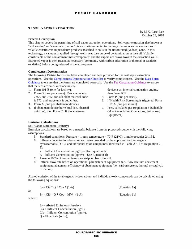
P E R M I T H A N D B O O K
SOURCE-SPECIFIC GUIDANCE
166
9.2 SOIL VAPOR EXTRACTION
by M.K. Carol Lee
October 23, 2018
Process Description
This chapter covers the permitting of soil vapor extraction operations. Soil vapor extraction also known as
"soil venting" or "vacuum extraction", is an in situ remedial technology that reduces concentrations of
volatile constituents in petroleum products adsorbed to soils in the unsaturated (vadose) zone. In this
technology, a vacuum is applied through wells near the source of contamination in the soil. Volatile
constituents of the contaminant mass "evaporate" and the vapors are drawn toward the extraction wells.
Extracted vapor is then treated as necessary (commonly with carbon adsorption or thermal or catalytic
oxidation) before being released to the atmosphere.
Completeness Determination
The following District forms should be completed and fees provided for the soil vapor extraction
operations. Use the Completeness Determination Checklist to verify completeness. Use the Data Form
Guidance to ensure that the forms are completed correctly. Use the Fee Calculation Guidance to ensure
that the fees are calculated accurately.
1. Form 101-B (one for facility).
2. Form G (one per source). Process code is
7353, and 7353 for sub-slab; material code
is 572, and usage unit is cubic feet.
3. Form A (one per abatement device).
4. If abatement device burns fuel (i.e., thermal
oxidizer), then Form C. If the abatement
device is an internal combustion engine,
then Form ICE.
5. Form P (one per stack).
6. If Health Risk Screening is triggered, Form
HRSA (one per source).
7. Fees, calculated per Regulation 3 (Schedule
G1 – Remediation Operations, Soil – Any
Equipment).
Emission Calculations
Soil Vapor Extraction (Primary)
Emission calculations are based on a material balance from the proposed source with the following
assumptions:
5. Standard conditions: Pressure = 1 atm; temperature = 70oF (21oC); 1 mole occupies 24.15 L
6. Influent concentrations based on estimates provided by the applicant for total organic
hydrocarbons (POC), and individual toxic compounds, identified in Table 2-5-1 of Regulation 2-
5):
a. Influent Concentration (ug/L) – Use Equation 1a
b. Influent Concentration (ppmv) – Use Equation 1b
7. Assume 100% of contaminants are stripped from the soil.
8. Influent flow rate based on operational parameters of equipment (i.e., flow rate into abatement
equipment; abatement efficiency of abatement equipment (i.e., carbon system, thermal or catalytic
oxidation).
Abated emission of the total organic hydrocarbons and individual toxic compounds can be calculated using
the following equations:
EP = Cia * Q * Coa * (1-A) [Equation 1a]
or
EP = Cib * Q * Cob * MW *(1-A) [Equation 1b]
where:
EP = Abated Emissions (lbs/day),
Cia = Influent Concentration (ug/L),
Cib = Influent Concentration (ppmv),
Q = Flow Rate (scfm),

P E R M I T H A N D B O O K
SOURCE-SPECIFIC GUIDANCE
167
Coa = Dimensional Constant (Conversion Factor) for Equation 1a,
Coa = 1 lb/4.536E8 ug * 28.317 L/ft3 * 1440 min/day = 8.99E-5 lb-L-min/ug-ft3-day
Cob = Dimensional Constant (Conversion Factor) for Equation 1b,
Cob = 1 mole/24.15 L * 1 lb/454 g * 28.317 L/ft3 * 1440 min/day = 3.7 lb-mole-min/g-ft3-day
MW = Molecular Weight of Pollutant (g/mole) [i.e., molecular weight for “weathered gasoline” is
100 g/mole; molecular weight for benzene is 78 g/mole], and
A = Abatement Efficiency of Abatement Device (wt%)
Annual emissions are calculated by multiplying daily emissions by the maximum number of operating
hours per year (i.e., 365 days per year).
Abatement Device Emissions (Secondary)
Per Regulation 2-2-212, the aggregate sum of all increases of any given pollutant from a facility pursuant to
the authority to construct or permit to operate is included in the cumulative increase. Hence, in addition to
abated emissions of soil vapor extraction (“primary” emissions), emissions from the abatement device
(“secondary” emissions) must also be calculated. Because the abatement device requires a permit, per
Regulation 2-1-113.2.4, any “secondary” emissions from the abatement device must also be included in the
cumulative increase.
Carbon Adsorption
There are no secondary emissions for the operation of a carbon adsorption system.
Thermal/Catalytic Oxidation
However, the combustion of fuel from thermal and catalytic oxidizers and internal combustion engines
results in secondary criteria pollutants of combustion. These secondary pollutants must be calculated and
included in the cumulative increase. Furthermore, per Regulation 2-2-112, although the abatement
equipment is not be subject to BACT requirements when it is used to abate a source to meet
BACT/TBACT requirements, it is subject to Reasonably Available Control Technology (RACT) for
control of secondary pollutants. Policy: NOx and CO RACT Levels for Thermal Oxidizers has been
established:
NOx = 0.2 lb/MMBTU
CO = 0.8 lb/MMBTU
Per District Policy: NOx and CO RACT Levels for Thermal Oxidizers, source testing of the thermal and
catalytic oxidizers are required to verify nitrogen oxide and carbon monoxide emission requirements, if the
oxidizer is over 7.5 MMBTU/hr.
Emission factors from AP-42, Table 1.4-2 (Natural Gas Combustion) may be used for particulate (PM10),
sulfur dioxide (SO2), and POC emissions, unless vendor data for the abatement device is available:
PM10 = 7.6 lb/MM scf *(scf/1020 BTU) = 0.0075 lb/MMBTU
SO2 = 0.6 lb/MM scf *(scf/1020 BTU) = 0.0006 lb/MMBTU
POC = 5.5 lb/MM scf *(scf/1020 BTU) = 0.0054 lb/MMBTU
With these emission factors, the annual emissions from the thermal/catalytic oxidizer can be calculated
using the following equation:
ES = F x B x H

P E R M I T H A N D B O O K
SOURCE-SPECIFIC GUIDANCE
168
where:
ES = Annual Emissions of Abatement Device (lbs/yr)
F = Emission Factor of Criteria Pollutant (lb/MMBTU)
B = Maximum Firing Rate of Burner in Abatement Device (MMBTU/hr)
H = Maximum Number of Hours The Oxidizer Will Operate
(i.e., 24 hr/day x 365 day/yr = 8760 hrs/yr)
Internal Combustion (IC) Engines
The use of IC engines for abatement of the soil vapor extraction operations is infrequent. When IC engines
are used, the supplementary fuel is usually natural gas or propane. RACT for IC engines is Regulation 9-8
standards:
NOx (Rich Burn) = 56 ppmv @ 15 ppmv O2 = 0.2 lb/MMBTU
NOx (Lean Burn) = 140 ppmv @ 15 ppmv O2 = 0.5 lb/MMBTU
CO = 2000 ppmv @ 15 ppmv O2 = 4.3 lb/MMBTU
Initial startup source testing should be required to ensure that the IC engine (> 250 HP) will meet the
emission standards for nitrogen oxides and carbon monoxide, per Regulation 9-8 requirements.
Emission factors from AP-42, Table 3.2-1 (Uncontrolled Emission Factors from 2-Stroke Lean Burn
Engines) may be used for particulate (PM10), sulfur dioxide (SO2), and POC emissions, unless vendor data
for the abatement device is available:
PM10 = 3.84 E-2 lb/MMBTU
SO2 =5.88 E-4 lb/MMBTU
POC = 1.2E-1 lb/MMBTU
With these emission factors, the annual emissions from the IC engine can be calculated using the following
equation:
ES = F x B x H
where:
ES = Annual Emissions of Abatement Device (lbs/yr)
F = Emission Factor of Criteria Pollutant (lb/MMBTU)
B = Maximum Firing Rate of Burner in Abatement Device (MMBTU/hr)
H = Maximum Number of Hours The IC Engine Will Operate
(i.e., 24 hr/day x 365 day/yr = 8760 hrs/yr)
Applicable Requirements
District Rules and Regulations
Soil vapor extraction operations are subject to Regulation 8-47 (Air Stripping and Soil Vapor Extraction
Operations) ; which requires at least 90% control of emissions unless the applicant meets the exemptions of
Sections 109 through 113 of that regulation.
Any IC engines over 250 HP used for abatement of the soil vapor extraction operation would also be
subject to Regulation 9-8 (Nitrogen Oxide and Carbon Monoxide Emissions From Stationary Internal
Combustion Engines). Initial startup source testing should be required to ensure that the IC engine (> 250
HP) will meet the emission standards for nitrogen oxides and carbon monoxide.

P E R M I T H A N D B O O K
SOURCE-SPECIFIC GUIDANCE
169
Best Available Control Technology (BACT)
The following are applicable BACT requirements for:
Soil Vapor Extraction
Inform the BACT Coordinator of updates to the BACT/TBACT Workbook.
California Environmental Quality Act (CEQA)
Permit applications which are reviewed following the specific procedures, fixed standards and objective
measurements set forth in this chapter (9.2) are classified as ministerial and will accordingly be exempt
from CEQA review per Regulation 2-1-311.
In addition to the above-mentioned source-specific applicable requirements, other requirements may also
be applicable depending on the facility, its application emissions, and its source location:
Offsets
Prevention of Significant Deterioration
School Notification
Health Risk Screening Analysis
Permit Conditions
Standardized conditions for soil vapor extraction operations (including that for RACT requirements for
thermal oxidizers and IC engines) are available from the Permit Condition Guidance. Refer to the
Evaluation Report Template Guidance to obtain the Microsoft Word formatted permit conditions for this
source category.

P E R M I T H A N D B O O K
SOURCE-SPECIFIC GUIDANCE
170
10.1 CHROME PLATING (HEXAVALENT)
by M.K. Carol Lee
October 23, 2018
Process Description
This chapter covers the permitting of chrome plating operations. Chrome plating is a finishing treatment
utilizing the electrolytic deposition of chromium. These operations fall into three general categories as
follows: hard (or technical) chrome plating, decorative (or bright) chrome plating, and hard chrome
anodizing. Decorative chrome plating is further divided into two permit categories, hexavalent (+6 valence
state) chrome based decorative plating and trivalent (+3 valence state) chrome based decorative plating.
Air emissions result from these processes when byproduct hydrogen or air (air sparging is ocassionally
used for mixing or cooling) leaves the bath carrying bath chemicals into the atmosphere in particulate
(mist) form. Although other variants of the above chrome plating processes exist, including Porous
Chrome Plating, Brush Chrome Plating and Black Chrome Plating, this chapter focuses mainly on the most
prevalent plating operations, hard chrome plating, decorative chrome plating and trivalent chrome plating.
Hard chrome plating usually involves plating at high current densities for time periods measured in
multiple hours to produce plating thicknesses ranging from 20 to 100 µm. Decorative chrome plating, on
the other hand, is conducted at relatively lower current densities for time periods measured in minutes to
produce plating thicknesses that are typically less than 1 µm, but some decorative plating operations may
plate up to 10 µm.
Although both hexavalent and trivalent chrome compounds are listed on the various hazardous (toxic)
materials lists, only hexavalent chrome has been identified to be a human carcinogen. Therefore, those
plating operations that involve hexavalent chrome-based bath chemistry (decorative, hard chrome and hard
anodizing) require a health risk screening analysis and are subject to the Statewide ATCM for chrome
plating (Regulation 11, Rule 8) as well as new source review requirements (Regulation 2, Rule 2).
Decorative Trivalent Chrome Plating is subject to new source review requirements (Regulation 2, Rule 2)
as well as the Statewide ATCM for chrome plating (Regulation 11, Rule 8) only. No health risk screening
analysis is required for trivalent chrome plating at this time.
Completeness Determination
The following District forms should be completed and fees provided for chrome plating. Use the
Completeness Determination Checklist to verify completeness. Use the Data Form Guidance to ensure that
the forms are completed correctly. Use the Fee Calculation Guidance to ensure that the fees are calculated
accurately.
1. Form 101-B (one for facility).
2. Form G (one per source). Process code is
3070 for decorative chrome plating
(<=50000 Amphr), 3071 for hard chrome
plating, 3079 for decorative trivalent
chrome, and 3080 for decorative chrome (>
500000 Amphr); material code is 477; and
usage unit is amp-hr. The pollutant code is
1095 for hard and decorative chrome plating
and 1340 for trivalent chrome.
3. Form A (one per abatement device).
4. A Health Risk Screening is triggered, Form
HRSA (one per source).
5. Fees, calculated per Regulation 3 (Schedule
G1) for Sterilization Equipment (Ethylene
Oxide).
Emission Calculations
Hard Chrome
In general, the emission standards of Section 93102, Subchapter 7.5, Chapter 1, Division 3, Title 17, of the
California Code of Regulations: “Hexavalent Chrome Airborne Toxic Control Measure For Chrome Plating
and Chromic Acid Anodizing Operations” should be used to estimate emissions from hard chrome platers.
(see Section 93102(c)(1)).
With the emission factors and the project throughput (in amp-hr/year), the emissions of hexavalent chrome
can be estimated:
PM10 (lbs/yr) = CrVI+= Throughput (amp-hr/yr) x Emission Factor (mg/amp-hr) x (1.0E-03 g/mg) x

P E R M I T H A N D B O O K
SOURCE-SPECIFIC GUIDANCE
171
(2.203E-3 lb/g)
Decorative Chrome
For decorative chrome plating, emission calculations are based on source test data for decorative chrome
plating operations. This information may be found in the California Air Resources Board (CARB)
document "Control of Emissions from Electroplating and Anodizing Operations" December, 1988:
Decorative Chrome Plating: 0.5 mg/amp-hr
Abatement Efficiency of Mist Suppressant: 95% (factor=0.05)
With the specified emission factors and the project throughput (in amp-hr/year), the emissions of
hexavalent chrome can be estimated:
PM10 (lbs/yr) = CrVI+= Throughput (amp-hr/yr) x Emission Factor (mg/amp-hr) x (1.0E-03 g/mg) x
(2.203E-3 lb/g)
Trivalent Chrome
A search of Internet, the known available literature including AP-42 all indicate the emissions of
trivalent chrome, if any, have not been quantified at the present time. The trivalent chrome plating
bath chemistry is much more dilute than hexavalent chrome, therefore any emissions created by
hydrogen gas production and entrainment would be expected to be much lower than for a similar
hexavalent chrome bath. To minimize any potential emissions, the trivalent chrome chemicals
include an additive that is a wetting agent, thereby reducing the surface tension and reducing
emissions of plating bath solution. For the purposes of this evaluation, trivalent chrome plating
bath emissions are estimated to be negligible.
It should be noted that wetting agent is included in the bath formulation to facilitate optimal bonding of the
trivalent chrome metal with the substrate being plated. The reduced emissions potential is a side benefit to
the desired low surface tension created by the wetting agent already included in the bath chemicals. It
should also be established that the presence of any hexavalent chrome constitutes a contaminated bath,
compromising the quality of the trivalent chrome plating process. For this reason, it is assumed that there
is no hexavalent chrome present or emitted.
Applicable Requirements
District Rules and Regulations
The provisions of Section 93102, Subchapter 7.5, Chapter 1, Division 3, Title 17, of the California Code of
Regulations: “Hexavalent Chrome Airborne Toxic Control Measure For Chrome Plating and Chromic Acid
Anodizing Operations” were incorporated by reference in Regulation 11-8.
Best Available Control Technology (BACT)
The following are applicable BACT requirements for:
Chrome Plating
- Chrome Plating - Decorative Chrome
Chrome Plating - Hard Chrome
- Rectifier throughput 0 to 6,053,333amp-hr/yr
- Rectifier throughput 6,053,333 to 151,333,333amp-hr/yr
- Rectifier throughput >= 151,333,333amp-hr/yr
Inform the BACT Coordinator of updates to the BACT/TBACT Workbook.
NESHAPS
A chrome plater is subject to the National Emission Standards for Chromium Emissions From Hard and
Decorative Chrome Electroplating and Chromium Anodizing Tanks if it emits more than 10 tons per year
of hexavalent chrome (or other hazardous air pollutant). The chrome plating ATCM has been granted

P E R M I T H A N D B O O K
SOURCE-SPECIFIC GUIDANCE
172
equivalency with the Federal NESHAP. Hence, compliance with the ATCM is compliance with the
NESHAP.
California Environmental Quality Act (CEQA)
Permit applications which are reviewed following the specific procedures, fixed standards and objective
measurements set forth in this chapter (10.1) are classified as ministerial and will accordingly be exempt
from CEQA review per Regulation 2-1-311.
In addition to the above-mentioned source-specific applicable requirements, other requirements may also
be applicable depending on the facility, its application emissions, and its source location:
Offsets
Prevention of Significant Deterioration
School Notification
Risk Screening Analysis
Permit Conditions
Standardized conditions for chrome plating are available from the Permit Condition Guidance. Refer to the
Evaluation Report Template Guidance to obtain the Microsoft Word formatted permit conditions for this
source category.

P E R M I T H A N D B O O K
SOURCE-SPECIFIC GUIDANCE
173
10.2 ETHYLENE OXIDE STERILIZERS
by M.K. Carol Lee
October 23, 2018
Process Description
This chapter covers the permitting of ethylene oxide (EtO) sterilizers. EtO sterilization or fumigation is
typically performed at industrial/commercial facilities and hospitals in sealed, airtight chambers. Most
sterilizers use either 100% pure EtO, or a mixture of 12%(wt) EtO and 88%(wt) Freon-12 (CFC).
The EtO sterilization process usually employs five steps:
1. Presterilization conditioning,
2. Sterilization,
3. Evacuation,
4. Air wash,
5. Aeration.
Conditioning includes sealing and evacuating the loaded chamber, then adjusting temperature and pressure.
The sterilization step involves adding the sterilant, establishing the correct operating pressure and
temperature and holding the chamber for a soaking period of 4 to 24 hours. The chamber pressure should
be slightly below atmospheric for pure EtO or two atmospheres for 12/88 mixtures. After soaking, the
chamber is evacuated, then given a series of air washes to finish removing EtO. Any residual EtO in the
sterilized product is removed by aeration, which may be done either in the sterilizer chamber or in a
specially designed aeration chamber (SCAQMD, 1990).
Completeness Determination
The following District forms should be completed and fees provided for ethylene oxide sterilizers. Use the
Completeness Determination Checklist to verify completeness. Use the Data Form Guidance to ensure that
the forms are completed correctly. Use the Fee Calculation Guidance to ensure that the fees are calculated
accurately.
1. Form 101-B (one for facility).
2. Form G (one per source). Process code is
7146 for medical equipment sterilization and
1032 for food/pharmaceutical products
sterilization; material code is 487; and usage
unit is in pounds.
3. Form A (one per abatement device).
4. If Health Risk Screening is triggered, Form
HRSA (one per source).
5. Fees, calculated per Regulation 3 (Schedule
G1) for Sterilization Equipment (Ethylene
Oxide).
Emission Calculations
Ethylene Oxide Sterilizer Emissions (Primary)
Emissions from ethylene oxide sterilizers should be calculated as the total sterilant gas throughput minus
the amount of inert gas present. Approximately 90% of the emissions can be attributed to the sterilizer
chamber and 10% to the aerator. These emissions will be reduced to the levels required by the ATCM for
ethylene oxide sterilizers.
POC = Ethylene Oxide = (lbs/yr of Sterilizer)(% of EtO in Sterilizer)(1-%Required Control Efficiency)
NPOC = CFC = (lbs/yr of Sterilizer)(1-% of EtO in Sterilizer)
Abatement Device Emissions (Secondary)
Per Regulation 2-2-212, the aggregate sum of all increases of any given pollutant from a facility pursuant to
the authority to construct or permit to operate is included in the cumulative increase. Hence, in addition to
abated emissions of ethylene oxide sterilizer (“primary” emissions), emissions from the abatement device
(“secondary” emissions) must also be calculated. Because the abatement device requires a permit, per
Regulation 2-1-113.2.4, any “secondary” emissions from the abatement device must also be included in the
cumulative increase.
Thermal/Catalytic Oxidation

P E R M I T H A N D B O O K
SOURCE-SPECIFIC GUIDANCE
174
The combustion of fuel from thermal and catalytic oxidizers and internal combustion engines results in
secondary criteria pollutants of combustion. These secondary pollutants must be calculated and included in
the cumulative increase. Furthermore, per Regulation 2-2-112, although the abatement equipment is not be
subject to BACT requirements when it is used to abate a source to meet BACT/TBACT requirements, it is
subject to Reasonably Available Control Technology (RACT) for control of secondary pollutants. Policy:
NOx and CO RACT Levels for Thermal Oxidizers has been established:
NOx = 0.2 lb/MMBTU
CO = 0.8 lb/MMBTU
Per District Policy: NOx and CO RACT Levels for Thermal Oxidizers, source testing of the thermal and
catalytic oxidizers are required to verify nitrogen oxide and carbon monoxide emission requirements, if the
oxidizer is over 7.5 MMBTU/hr.
Emission factors from AP-42, Table 1.4-2 (Natural Gas Combustion) may be used for particulate (PM10),
sulfur dioxide (SO2), and POC emissions, unless vendor data for the abatement device is available:
PM10 = 7.6 lb/MM scf *(scf/1020 BTU) = 0.075 lb/MMBTU
SO2 = 0.6 lb/MM scf *(scf/1020 BTU) = 0.0006 lb/MMBTU
POC = 5.5 lb/MM scf *(scf/1020 BTU) = 0.0054 lb/MMBTU
With these emission factors, the annual emissions from the thermal/catalytic oxidizer can be calculated
using the following equation:
ES = F x B x H
where:
ES = Annual Emissions of Abatement Device (lbs/yr)
F = Emission Factor of Criteria Pollutant (lb/MMBTU)
B = Maximum Firing Rate of Burner in Abatement Device (MMBTU/hr)
H = Maximum Number of Hours The Oxidizer Will Operate
(i.e., 24 hr/day x 365 day/yr = 8760 hrs/yr)
Applicable Requirements
District Rules and Regulations
The provisions of Section 93108 and 93108.5, Title 17, of the California Code of Regulations: “Ethylene
Oxide ATCM for Sterilizers and Aerators, Part 1 and 2” were incorporated by reference in Regulation 11-9.
Best Available Control Technology (BACT)
The following are applicable BACT requirements for:
Ethylene Oxide Sterilizers
- Ethylene Oxide Sterilization
Inform the BACT Coordinator of updates to the BACT/TBACT Workbook.
NESHAPS
Ethylene oxide sterilizers are subject to the NESHAPS, Subpart O: Commercial Sterilizers (Ethylene
Oxide Emission Standards for Sterilization Facilities). If a facility uses less than 1 ton of ethylene oxide
per year (all consecutive 12-month periods after December 6, 1996), then it is subject to only the
recordkeeping requirements of the standard (Section 63.367). If the facility uses 1 ton or more of ethylene
oxide per year, then it is also subject to the emission standards of the Sterilizer NESHAP. Which emission
standards apply depend on whether or not 10 or more tons of ethylene oxide per year are used. The
NESHAP standards apply based on ethylene oxide usage, not ethylene oxide emissions. The permit

P E R M I T H A N D B O O K
SOURCE-SPECIFIC GUIDANCE
175
engineer should review the application to determine whether the NESHAP applies and whether the
applicant complies if it does.
California Environmental Quality Act (CEQA)
Permit applications which are reviewed following the specific procedures, fixed standards and objective
measurements set forth in this chapter (10.2) are classified as ministerial and will accordingly be exempt
from CEQA review per Regulation 2-1-311.
In addition to the above-mentioned source-specific applicable requirements, other requirements may also
be applicable depending on the facility, its application emissions, and its source location:
Offsets
Prevention of Significant Deterioration
School Notification
Risk Screening Analysis
Permit Conditions
Standardized conditions for bulk loading operations are available from the Permit Condition Guidance.
Refer to the Evaluation Report Template Guidance to obtain the Microsoft Word formatted permit
conditions for this source category.

P E R M I T H A N D B O O K
SOURCE-SPECIFIC GUIDANCE
176
10.4 NON-HALOGENATED SOLVENT DRYCLEANING
by M.K. Carol Lee
October 23, 2018
Process Description
This chapter covers the permitting of non-halogenated (i.e., petroleum) solvent dry cleaning operations.
Petroleum solvents, as distinguished from synthetic solvents (which include halogenated solvents such as
perchloroethylene), are defined as any non-halogenated hydrocarbon solvent. Types of non-halogenated
solvent include Stoddard, 140F solvent. Dry Cleaning facilities using synthetic solvents are covered under
a different permit handbook chapter (10.5).
Additional background information is available from Chapter 4.1Dry Cleaning of AP-42 (Fifth Edition,
Volume I).
Any dry cleaning facility which uses (gross consumption) less than 200 gallons of petroleum solvent or any
other non-halogenated solvent in any single year is exempt from permitting requirements per Regulation 2-
1-120. However, they are subject to the registration requirements per Regulation 8-17-404. Details of how
to qualified dry cleaning equipment can be registered can be found on-line at the District’s web site.
Completeness Determination
The following District forms should be completed and fees provided for the non-halogenated solvent
drycleaners (which are not exempt per Regulation 2-1-120). Use the Completeness Determination
Checklist to verify completeness. Use the Data Form Guidance to ensure that the forms are completed
correctly. Use the Fee Calculation Guidance to ensure that the fees are calculated accurately.
1. Form 101-B (one for facility).
2. Form D (one per source).
3. If abated, Form A (one per abatement
device).
4. If Health Risk Screening is triggered, Form
D(a) (one per source).
5. Fees, calculated per Regulation 3 (Schedule
I).
Emission Calculations
Emissions from petroleum solvent dry cleaning operations should be calculated based on the estimated net
solvent evaporation. The District has developed instructions for the dry cleaner Annual Update Form to
assist dry cleaners in calculating net solvent evaporation.
POC in lb/yr = Net Solvent Evaporation (gals/yr) x Density of Solvent (lb/gal)
Applicable Requirements
District Rules and Regulations
Petroleum solvent dry cleaning operations are subject to Regulation 8-17. The standards of Regulation 8-
17 do not currently reflect the latest technologies of dry cleaning. Almost all non-halogenated solvent
drycleaners use closed loop machines (ventless dry-to-dry systems with internal refrigerated condenser),
which have been deemed by the District to be equivalent or better to complying with the requirements of
Regulation 8-17. Regulation 8-17 will be amended in the near future, upon which time this permit
handbook will also be amended to reflect the new requirements.
Best Available Control Technology (BACT)
The following are applicable BACT requirements for:
Petroleum Solvent Drycleaning
- Drycleaner - Petroleum Solvent
Inform the BACT Coordinator of updates to the BACT/TBACT Workbook.

P E R M I T H A N D B O O K
SOURCE-SPECIFIC GUIDANCE
177
California Environmental Quality Act (CEQA)
Permit applications which are reviewed following the specific procedures, fixed standards and objective
measurements set forth in this chapter (10.4) are classified as ministerial and will accordingly be exempt
from CEQA review per Regulation 2-1-311.
In addition to the above-mentioned source-specific applicable requirements, other requirements may also
be applicable depending on the facility, its application emissions, and its source location:
Offsets
Prevention of Significant Deterioration
School Notification
Risk Screening Analysis
Permit Conditions
Standardized conditions for petroleum solvent drycleaning are available from the Permit Condition
Guidance. Refer to the Evaluation Report Template Guidance to obtain the Microsoft Word formatted
permit conditions for this source category.

P E R M I T H A N D B O O K
SOURCE-SPECIFIC GUIDANCE
178
10.5 SYNTHETIC SOLVENT DRYCLEANING
by M.K. Carol Lee
October 23, 2018
Process Description
This chapter covers the permitting of synthetic solvent drycleaning operations. Synthetic solvents used for
drycleaning include perchloroethylene (perc) and n-propyl bromide. Trichlorotrifluroethane (freon,
fluorocarbon) and trichloroethane (TCA) are no longer used because of ozone depletion concerns. Dry
Cleaning facilities using non-halogenated solvents are covered under a different permit handbook chapter
(10.4).
Additional background information is available from Chapter 4.1 Dry Cleaning of AP-42 (Fifth Edition,
Volume I).
Completeness Determination
The following District forms should be completed and fees provided for the dry cleaning facilities. Use the
Completeness Determination Checklist to verify completeness. Use the Data Form Guidance to ensure that
the forms are completed correctly. Use the Fee Calculation Guidance to ensure that the fees are calculated
accurately.
1. Form 101-B (one for facility).
2. Form D (one per source).
3. If Health Risk Screening is triggered, Form
D(a) (one per source).
4. Fees, calculated per Regulation 3 (Schedule
I).
Emission Calculations
Emissions from synthetic solvent dry cleaning operations should be calculated based on the estimated net
solvent evaporation. The District has developed instructions for the dry cleaner Annual Update Form to
assist dry cleaners in calculating net solvent evaporation.
VOC in lb/yr = Net Solvent Evaporation (gals/yr) x Density of Solvent (lb/gal)
Perc is a NPOC; n-propyl bromide is a POC.
Applicable Requirements
District Rules and Regulations
Synthetic solvent dry cleaning operations are subject to Regulation 11-16. In addition, perchloroethylene
dry cleaning operations are also subject to the Airborne Toxic Control Measure (ATCM) for Emissions of
Perchloroethylene from Dry Cleaning Operations, which includes equipment requirements and a summary
of compliance times for existing and new facilities.
Perc is a carcinogen and N-propyl bromide is a compound undergoing review by OEHHA (i.e.,
reproductive effects and both toxics are subject to Regulation 2-5-301 (Best Available Control Technology
for Toxics (TBACT) Requirements)and 302 (Project Risk Requirements). The permit engineer should
ensure that the applicant uses TBACT in the dry cleaning operation and that the project risk is acceptable.
Best Available Control Technology (BACT)
The following are applicable BACT requirements for:
Synthetic Solvent Drycleaning
- Drycleaner - Perchloroethylene
- Drycleaner - Valclene & Other Synthetic Solvents
Inform the BACT Coordinator of updates to the BACT/TBACT Workbook.
NESHAPS

P E R M I T H A N D B O O K
SOURCE-SPECIFIC GUIDANCE
179
Dry cleaning facilities, which use perchloroethylene, are subject to the NESHAPS, Subpart M: Dry
Cleaning (National Perchloroethylene Air Emission Standards for Dry Cleaning Facilities). California’s
ATCM has been designed as equivalent to NESHAP and California has been delegated enforcement
authority by the U.S. EPA. On January 25, 2007, the California Air Resources Board approved the
amendments to the ATCM. These amendments have been incorporated into to Regulation 11-16 to include
all new ATCM requirements for perchloroethylene dry cleaning:
• Prohibit the installation of new Perc dry cleaning machines beginning on January 1, 2008;
• Eliminate the use of existing Perc machines at co-residential facilities (facilities that share a wall
with, or are located in the same building , as a residence) by July 1, 2010.
• Require that converted machines, and machines that are 15 years or older, be removed from
service by July 1, 2010;
• Require that all Perc machines be removed from service once they become 15 years old (as a
result, all remaining Perc machines must be removed from service by January 1, 2023); and
• Expand good operating practices and recordkeeping and reporting requirements.
and a definition for non-halogenated solvents:
8-17-201 Non-halogenated Solvent: For the purposes of this rule only, this definition applies to the following solvent
compounds used for dry cleaning that do not contain one or more halogens (chlorine, bromine, fluorine, or iodine).
Non-halogenated solvents typically, but not necessarily, contain hydrogen and carbon. 201.1 Solvent: For the purposes of this regulation only, “solvent” refers to any nonhalogenated solvent
subject to this rule.
201.2 Non-halogenated solvents include, but are not limited to, petroleum solvents, glycol ethers, and volatile methylated siloxanes:
201.2.1. Petroleum Solvent: A clear hydrocarbon distillate used for dry cleaning - typically
having a minimum flash point of 38oC (100oF) (generically known as Stoddard solvent).
201.2.2. High Flash Petroleum Solvent: A highly refined hydrocarbon solvent with a flash
point above 60oC (140oF); typically a mixture of aliphatic hydrocarbons in the C8-
C14 range [e.g. DF2000, Ecosolve™, Drylene®, Puredry™].
201.2.3. Glycol Ether Solvent: A clear colorless glycol ether/ester based liquid used for dry
cleaning - typically having a minimum flash point of 85oC (185oF). These solvents include, but are not limited to Propylene Glycol Ethers, Dipropylene Glycol Tert
Butyl Ether, Aliphatic Propylene Glycol Ethers, Propylene Glycol Dipropylene
Glycol Normal Ether [e.g. Rynex®, Arcosolv® DPNB, Impress™]. 201.2.4. Volatile Methylated Siloxane Solvent: A clear colorless liquid containing a volatile
methyl siloxane called decamethylcyclopentasiloxane or D5 as the cleaning solvent.
- typically having a minimum flash point of 76oC (170oF) [e.g. Green Earth®].
California Environmental Quality Act (CEQA)
Permit applications which are reviewed following the specific procedures, fixed standards and objective
measurements set forth in this chapter (10.5) are classified as ministerial and will accordingly be exempt
from CEQA review per Regulation 2-1-311.
In addition to the above-mentioned source-specific applicable requirements, other requirements may also
be applicable depending on the facility, its application emissions, and its source location:
Offsets
Prevention of Significant Deterioration
School Notification
Risk Screening Analysis
Permit Conditions
Standardized conditions for synthetic solvent dry cleaning operations are available from the Permit
Condition Guidance. Refer to the Evaluation Report Template Guidance to obtain the Microsoft Word
formatted permit conditions for this source category.

P E R M I T H A N D B O O K
SOURCE-SPECIFIC GUIDANCE
180
11.1 ABRASIVE BLASTING OPERATIONS
by M.K. Carol Lee
October 23, 2018
Process Description
Abrasive blasting is the cleaning or preparing of a surface by forcibly propelling a stream of abrasive
material against the surface using sand, glassbead, aluminum oxide, grit, slag, garnet, steel shot, slag,
walnut shells, and others. Abrasive blasting is being used in many different applications to:
1. remove rust, scale, and paint;
2. roughen surfaces in preparation for bonding, painting or coating;
3. remove burr; and/or
4. develop a matte surface finish.
5. Remove flash from molding operation.
Abrasive blasting helps eliminate the use of organic solvent stripping and the generation of toxic waste
material. A wide range of abrasive blasting equipment is available and blasting conditions can be selected
to suit the coating and substrate. In most applications, the abrasive media are collected, cleaned to remove
coating debris, and reused. The abrasive media breakdown in use so they can not be reused indefinitely.
Once the particle size gets smaller, the stripping efficiency drops. The worn abrasive media must be
discarded and may require disposal.
There are two types of abrasive blasting:
1. Confined
2. Unconfined
Confined abrasive blasting is abrasive blasting, which is confined in an enclosure to reduce particulate
matter emissions to the atmosphere, while unconfined is not. This permit handbook chapter will discuss
both types.
A thorough explanation of abrasive blasting is available from Chapter 13.2.6, Abrasive Blasting, of AP-42
(Fifth Edition, Volume I). Generally, a District permit is required for any confined abrasive blasting
operation or equipment that has a confined volume greater than or equal to 100 cubic feet and is located in
building. If the confined abrasive blasting operation is less than 100 cubic feet and abated by a particulate
filter, it is exempt from permitting requirements per Regulation 2-1-118.1. In addition, blast cleaning
equipment used a suspension of abrasives in water is exempt per Regulation 2-1-118.2. Portable abrasive
blasting equipment used on a temporary basis within the District is exempt per Regulation 2-1-118.3.
Completeness Determination
The following District forms should be completed and fees provided for abrasive blasting operations. Use
the Completeness Determination Checklist to verify completeness. Use the Data Form Guidance to ensure
that the forms are completed correctly. Use the Fee Calculation Guidance to ensure that the fees are
calculated accurately.
1. Form 101-B (one for facility).
2. Form G (one per source).
3. If Health Risk Screening is triggered, Form
HRSA (one per source).
4. Fees, calculated per Regulation 3 (Schedule
F).
Emission Calculations
Particulate matter (PM) and particulate hazardous air pollutants (HAP) are the major concern relative to
abrasive blasting. Table 13.2.6-1 in Chapter 13.2.6, Abrasive Blasting, of AP-42 (Fifth Edition,
Volume I).

P E R M I T H A N D B O O K
SOURCE-SPECIFIC GUIDANCE
181
Presents total PM emission factors for abrasive blasting as a function of wind speed. However, emissions
of PM10 and PM2.5 are not significantly wind dependent.
Emission Factors for Abrasive Blasting
Unconfined and uncontrolled PM10 = 13 lb/1000 lb of Abrasive
Confined and controlled by fabric filter PM10 = 0.69 lb/1000 lb of Abrasive
The following equation can be used to calculate daily and annual PM10 emission rates:
EPM10 = U(EF)[1-(A/100)]
where,
E = emissions of PM10 (lb/hr)
U = blast media usage (lb/day or lb/yr)
EF = emission factor (lb/1000 lb)
A = abatement efficiency (%)
However, an alternative method is to use the grain loading rates and exhaust rates from the particulate
abatement devices for confined abrasive blasting operations to calculate particulate emissions.
EPM10 = Qdry(gr)(60 min/hr)/7000 gr/lb
where,
E = emissions of PM10 (lb/hr)
Qdry = dry volumetric flow rate (cfm)
gr = grain loading rate (gr/dscf)
The standard cubic feet of dry air exhaust can be calculated from actual exhaust rates using the following
equation:
Qdry = Qact[(68 + 460)/(Tact +460)](1-%H2O)
where,
Qdry = dry volumetric flow rate (cfm)
Qact = actual volumetric flow rate (cfm), including water vapor
Tact = actual temperature of exhaust (oF)
%H2O = weight fraction of water vapor
AIR TOXICS
According to Chapter 13.2.6, Abrasive Blasting of AP-42, hazardous air pollutants, typically particulate
metals, are emitted from some abrasive blasting operations. These emissions are dependent on both the
abrasive material and the targeted surfaces. The permit engineer should assume the same percentage of
toxics in the resulting emissions of PM10 as found in the abrasive material used.
Applicable Requirements
District Rules and Regulations
In general, the unconfined abrasive blasting operation is subject to the operating standards of Regulation
12, Rule 4. With the proper operation and use of complying abrasive blasting media, the unconfined
operation should comply with the operating standards of Regulation 12, Rule 4. Permit conditions are
imposed to ensure compliance with Regulation 12, Rule 4.
Confined abrasive blasting operations are subject to the operating standards of Regulation 6-1. Permit
conditions are imposed to ensure compliance with Regulation 6-1.

P E R M I T H A N D B O O K
SOURCE-SPECIFIC GUIDANCE
182
Best Available Control Technology (BACT)
BACT for the abrasive blasting operations is specified in the BACT/TBACT Workbook. The following are
applicable BACT requirements for:
Abrasive Blasting
- Abrasive Blasting - Enclosed
Inform the BACT Coordinator of updates to the BACT/TBACT Workbook.
California Environmental Quality Act (CEQA)
Permit applications which are reviewed following the specific procedures, fixed standards and objective
measurements set forth in this chapter (11.5) are classified as ministerial and will accordingly be exempt
from CEQA review per Regulation 2-1-311.
In addition to the above-mentioned source-specific applicable requirements, other requirements may also
be applicable depending on the facility, its application emissions, and its source location:
Offsets
Prevention of Significant Deterioration
School Notification
Risk Screening Analysis
Permit Conditions
Standardized conditions for abrasive blasting operations are available from the Permit Condition Guidance.
Refer to the Evaluation Report Template Guidance to obtain the Microsoft Word formatted permit
conditions for this source category.

P E R M I T H A N D B O O K
SOURCE-SPECIFIC GUIDANCE
183
11.2 ASPHALT (HOT MIX) FACILITIES
by M.K. Carol Lee
October 23, 2018
Process Description
A hot mix asphalt (HMA) facility is an assembly of equipment where aggregates are blended, heated, dried,
and mixed with asphalt. An aggregate is any hard, inert mineral material used for mixing in graduated
particles or fragments. It includes sand, gravel, crushed stone, slag, rock dust or powder, and reclaimed
asphalt pavement [RAP]. Aggregate and RAP (if used) constitutes over 90 percent by weight of the total
mixture.1 A detailed description of the HMA facility is provided in Chapter 11.1 (Hot Mix Asphalt Plants)
of EPA’s AP-42.
There are two categories of HMA facilities: batch and drum mix. Most HMA facilities are comprised of
the same basic air pollution sources. These components are the dryer, asphalt cement heating and storage
(with dust collection system), and reclaimed asphalt paving (RAP) area. Storage tanks are used to store
heated liquid asphalts and asphalt cement at HMA facilities. Storage tanks at HMA facilities are usually
fixed roof (closed or enclosed) and vented due to the smaller size of the tanks, usually less than 30,000
gallons.
The following equipment is typically exempt from permitting requirements:
Description of Equipment Permit Exemption
Any heater or dryer with less than 10 million BTU/hr rated heat input if
fired exclusively with natural gas (including compressed natural gas),
liquefied petroleum gas (e.g., propane, butane, isobutene, propylene,
butylenes, and their mixtures), and any combination thereof.
2-1-114.2.1
Mixer and other ancillary sources at HMA facility with a maximum rated
production capacity less than 15 cubic yards per hour
2-1-115.1.1
Other sources at HMA facility with a maximum throughput less than 5000
tons per year
2-1-115.1.2
A crusher or grinder which processes exclusively material with a moisture
content greater than or equal to 20 percent by weight
2-1-115.1.3
The following which process exclusively material with a moisture content
greater than or equal to 5 percent by weight:
- Screen or other size classifier
- Conveyor, screw, auger, stacker or bucket elevator
- Grizzly, or other material loading or unloading
- Storage silos
- Storage or weigh hopper/bin system
2-1-115.1.4
Haul or access roads 2-1-115.1.5
Drilling or blasting 2-1-115.1.6
Containers, reservoirs, tanks, and loading equipment used exclusively for the storage or loading of petroleum oils with an ASTM D-93 (PMCC)
flash point of 130oF or higher, when stored or loaded at a temperature at
least 36oF below the flash point.
2-1-123.3.3
Containers, reservoirs, tanks, and loading equipment used exclusively for the storage or loading of asphalt or asphalt emulsion with a sulfur content
of less than 0.5 wt%. This does not include the storage of asphalt cutback
with hydrocarbons having an initial boiling point of less than 302oF.
2-1-123.3.7
Containers, reservoirs, tanks, and loading equipment used exclusively for the storage or transfer of an asphalt-water emulsion heated to 150oF or
less.
2-1-123.3.11
1 Chapter 11.1 (Hot Mix Asphalt Plants) of EPA’s AP-42, pg. 1.
P E R M I T H A N D B O O K
SOURCE-SPECIFIC GUIDANCE
184
The permitting of any heater used to provide indirect heat is covered in Chapter 2.1 (Boilers, Steam
Generators, & Process Heaters) of the permit handbook. The permit of any storage tanks is covered in
Chapter 4 (Organic Liquid Storage Tanks) of the permit handbook. This permit handbook will cover
asphalt mixers and dryers and ancillary storage sources (i.e., piles, silos, loadouts).
Completeness Determination
The following District forms should be completed and fees provided for HMA facilities. Use the
Completeness Determination Checklist to verify completeness. Use the Data Form Guidance to ensure that
the forms are completed correctly. Use the Fee Calculation Guidance to ensure that the fees are calculated
accurately.
1. Form 101-B (one for facility).
2. Form G (one per source).
3. Form C (one per dryer).
4. Form A (one per abatement device).
5. Form P (one per stack).
6. If Health Risk Screening is triggered, Form
HRSA (one per source).
7. Fees, calculated per Regulation 3 (Schedule
G-2 for Aggregate Dryers; Batch, Drum, and
Other Mixers and Schedule F for other
sources).
Emission Calculations [Batch Mix and Drum Mix]
Emissions from HMA plants may be divided into ducted production emissions, pre-production fugitive dust
emissions, and other production-related fugitive emissions. Pre-production fugitive dust sources associated
with HMA plants include vehicular traffic generating fugitive dust on paved and unpaved roads, aggregate
handling, and other aggregate processing operations.
Pre-production fugitive emissions – PM10 from vehicle traffic
Emissions from vehicle traffic on paved roads to and from the storage piles should also be accounted in the
emissions for the storage piles. A paved roads emission factor equation is provided in Chapter 13.2.1,
Paved Roads of AP-42 (Fifth Edition, Volume I) for vehicles traveling on paved surfaces:
E = k(sL/2)0.65(W/3)1.5-C lb/VMT
The following provides an explanation of the variables in the equation and the average values
recommended for use (only if actual more specific and precise values are not available), if the source-
specific values are not known:
E = Emission Factor (lb/VMT)
k = Particle size multiplier for particle size range and units of interest (see Table 13.2-1.1)
W = average weight (tons) of the vehicles traveling the road
C = emission factor for 1980’s vehicle fleet exhaust, brake wear and tire wear; C = 0.000472
The permit engineer should obtain information from the applicant regarding the maximum vehicle weight
and miles traveled per year by all vehicles involved on driving on the unpaved roads at the facility. If
watering is used to suppress dust, a maximum abatement efficiency of 70% may be used. If chemical dust
suppressants are used, a maximum abatement efficiency of 80% may be used3.
Pre-production fugitive emissions – PM10 from storage piles
Emission factors for storage piles are taken from Chapter 13.2.4, Aggregate Handling and Storage Piles, of
AP-42 (Fifth Edition, Volume I). These emission factors include emissions from drop operations into
storage piles:
E = k(0.0032)(U/5)1.3/(M/2)1.4
2 Table 13.2.1-2 of Chapter 13.2.1, Paved Roads, of AP-42 (Fifth Edition, Volume I), pg. 5. 3 Chapter 13.2.2, Unpaved Roads of AP-42 (Fifth Edition, Volume I), pg. 13.

P E R M I T H A N D B O O K
SOURCE-SPECIFIC GUIDANCE
185
The following provides an explanation of the variables in the equation and the average values
recommended for use, if the source-specific values are not known:
E = Emission Factor (lb/ton)
k = Particle size multiplier (dimensionless); PM10, k = 0.35
U = mean wind speed (miles/hr); U = 8.2
M = material moisture content (%); M = 2.4
E = (0.35)(0.0032)(8.2/5)1.3/(2.4/2)1.4
E = 1.65E-03 lb/ton [for storage piles]
For emissions from equipment traffic (truck, front-end loaders, dozer, etc.) traveling between or on piles, it
is recommended that the equation for vehicle traffic on unpaved surfaces be used (see Equation 1a). The
emissions from equipment traffic around the piles should be calculated using the same emission factors
noted previously for unpaved roads by including the VMT around these piles and including it in the total
estimated VMT on unpaved roads within the facility.
Emission factors for wind erosion for storage piles may be taken from AP-42, Fourth Edition, Section 8.19,
Table 8.19.1-1. These emission factors include emissions from wind erosion. Assuming the 3.5
lb/acre/day emission is for TSP emissions, the wind blown PM10 emissions would be approximately 50%
or:
EPM10 = 1.7 lb/acre/day
The permit engineer should obtain information from the applicant regarding the maximum area (in acres)
and throughput (in tons) that the storage piles will occupy and the number of days per year that the storage
piles will exist at the crushing and plant. If watering is used to suppress dust, a maximum abatement
efficiency of 70% may be used. If chemical dust suppressants are used, a maximum abatement efficiency
of 80% may be used4.
Furthermore, if railcars or ships are involved in the transportation of materials, then also the combustion
emissions from the use of these transport vehicles should also be calculated and included in the facilities
cumulative increase.
Pre-production dust emissions – Loadout and Silo Filling
Emission factors for HMA load-out and silo-filling operations can be estimated using the data in Tables
11.1-14, -15, and -16 of Chapter 11.1 (Hot Mix Asphalt Plants) of EPA’s AP-42. Table 11.1-14 presents
predictive emission factor equations for HMA loadout and silo filling operations. Tables 11.1-15 and -16
present speciation profiles for organic particulate-based and volatile particulate-based compounds,
respectively. The speciation profile shown in Table 11.1-15 can be applied to the extractable organic
particulate matter (PM) emission factors estimated by the equations in Table 11.1-14 to estimate emission
factors for specific organic PM compounds. The speciation profile presented in Table 11.1-16 can be
applied to the total organic carbon (TOC) emission factors estimated by the equations in Table 11.1-14 to
estimate emission factors for specific volatile organic compounds.
4 Chapter 11.1 (Hot Mix Asphalt Plants) of EPA’s AP-42, pg. 13.

P E R M I T H A N D B O O K
SOURCE-SPECIFIC GUIDANCE
186
Table 11.1-145
5 Chapter 11.1 (Hot Mix Asphalt Plants) of EPA’s AP-42, pg. 33.

P E R M I T H A N D B O O K
SOURCE-SPECIFIC GUIDANCE
187
Table 11.1-156
6 Chapter 11.1 (Hot Mix Asphalt Plants) of EPA’s AP-42, pg. 34.

P E R M I T H A N D B O O K
SOURCE-SPECIFIC GUIDANCE
188
Table 11.1-167
7 Chapter 11.1 (Hot Mix Asphalt Plants) of EPA’s AP-42, pg. 35.

P E R M I T H A N D B O O K
SOURCE-SPECIFIC GUIDANCE
189
Production Emissions
Chapter 11.1 (Hot Mix Asphalt Plants) of EPA’s AP-42 presents emission factors for batch mix and drum
mix HMA plants as follows:
Emission Factors for PM10 from HMA Plants8
Process PM10 Emission Factor (lb/ton)
Dryer, hot screens, mixer – Batch Mix HMA Plant
Uncontrolled 4.5
Fabric Filter (i.e., Baghouse) 0.027
Dryer – Drum Mix
Uncontrolled 6.5
Fabric Filter (i.e., Baghouse) 0.023
Emission Factors for CO, NOx, SO2, and POC from HMA Plants9
Process CO (lb/ton) NOx (lb/ton) SO2 (lb/ton) POC (lb/ton)
Natural Gas Dryer
Batch Mix 0.40 0.025 0.0046 0.0082
Drum Mix 0.13 0.026 0.0034 0.032
8 Chapter 11.1 (Hot Mix Asphalt Plants) of EPA’s AP-42, pg. 11-14. 9 Chapter 11.1 (Hot Mix Asphalt Plants) of EPA’s AP-42, pg. 15-18.
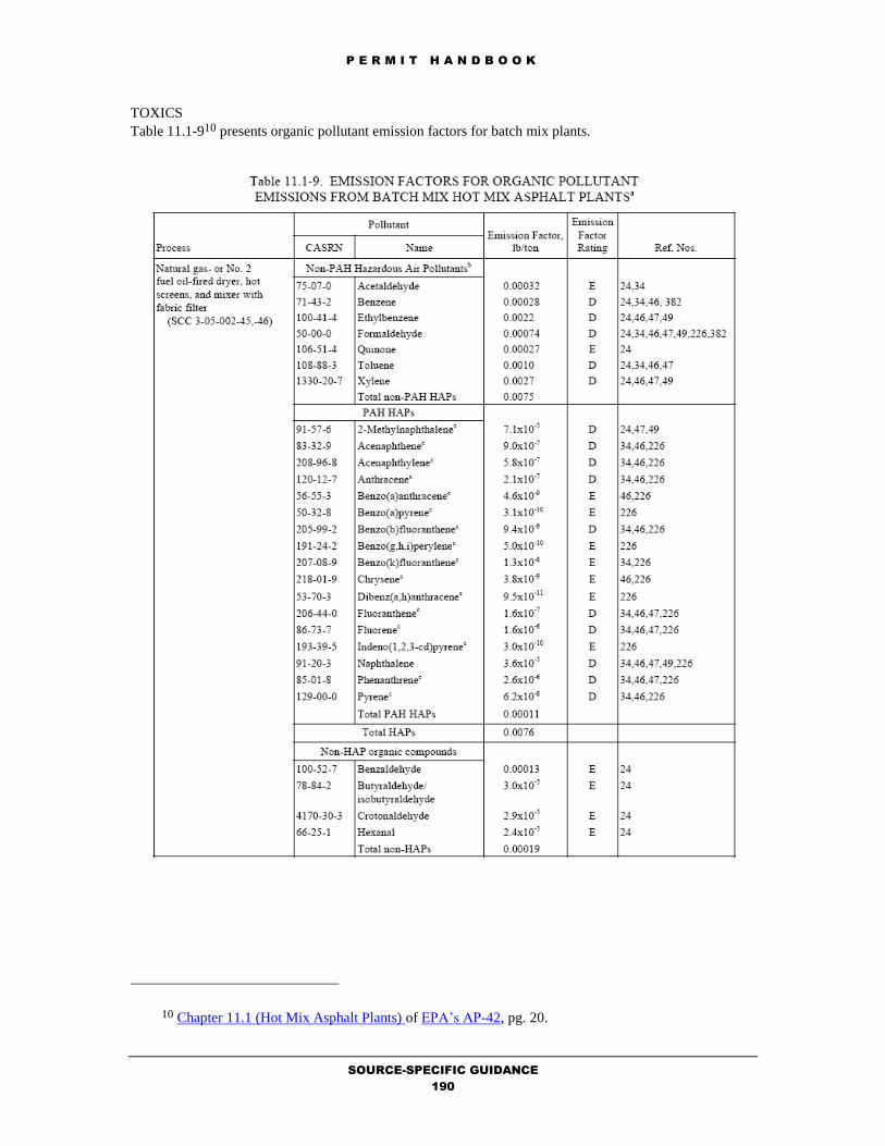
P E R M I T H A N D B O O K
SOURCE-SPECIFIC GUIDANCE
190
TOXICS
Table 11.1-910 presents organic pollutant emission factors for batch mix plants.
10 Chapter 11.1 (Hot Mix Asphalt Plants) of EPA’s AP-42, pg. 20.

P E R M I T H A N D B O O K
SOURCE-SPECIFIC GUIDANCE
191
Table 11.1-1011 presents organic pollutant emission factors for drum mix
plants.
11 Chapter 11.1 (Hot Mix Asphalt Plants) of EPA’s AP-42, pg. 21.

P E R M I T H A N D B O O K
SOURCE-SPECIFIC GUIDANCE
192

P E R M I T H A N D B O O K
SOURCE-SPECIFIC GUIDANCE
193
Tables 11.1-1112 and –1213 present metals emission factors for batch and drum mix plants, respectively.
12 Chapter 11.1 (Hot Mix Asphalt Plants) of EPA’s AP-42, pg. 29. 13 Chapter 11.1 (Hot Mix Asphalt Plants) of EPA’s AP-42, pg. 30.

P E R M I T H A N D B O O K
SOURCE-SPECIFIC GUIDANCE
194
Spreadsheets for Emission Calculations [Batch Mix and Drum Mix] are provided.
Applicable Requirements
District Rules and Regulations
In general, the particulate sources at HMA plants are subject to the operating standards of Regulation 6-1.
All but the transfer points of storage silos are fugitive in nature. The storage silos are generally abated by a
fabric filter or baghouse device. Fugitive sources include the transfer of sand and aggregate, truck loading,
mixer loading, vehicle traffic, and wind erosion from sand and aggregate storage piles. The amount of
fugitive emissions generated during the transfer operations depend primarily on the surface moisture
content of these materials. Types of controls used may include water sprays, enclosures, and baghouse
devices. With these controls of the equipment and good maintenance and wetting of unpaved road
surfaces, particulate emissions should comply with the operating standards of Regulation 6-1. Permit
conditions are imposed to ensure compliance with Regulation 6-1.
HMA facilities are subject to the Federal NSPS Subpart I for Hot Mix Asphalt Facilities, which prohibits
the owner/operator from discharging or causing to discharge into the atmosphere from any affected facility
any gases which: 1) Contain particulate matter in excess of 90 mg/dscm (0.04 gr/dscf); and 2) Exhibit 20%

P E R M I T H A N D B O O K
SOURCE-SPECIFIC GUIDANCE
195
opacity, or greater. Because these NSPS requirements are less restrictive than District BACT requirements
for HMA plants, new/modified HMA facilities should meet the NSPS.
Best Available Control Technology (BACT)
BACT for the sources at HMA plants are specified in the BACT/TBACT Workbook. The following are
applicable BACT requirements for:
Miscellaneous Operations
- Asphalt Batch Plant – Material Handling
- Asphalt (Hot Mix) Batch Mix Facilities
- Asphalt (Hot Mix) Drum Mix Facilities
- Asphalt Roofing Line
- Asphalt Storage Tank
Inform the BACT Coordinator of updates to the BACT/TBACT Workbook.
California Environmental Quality Act (CEQA)
Permit applications which are reviewed following the specific procedures, fixed standards and objective
measurements set forth in this chapter (11.5) are classified as ministerial and will accordingly be exempt
from CEQA review per Regulation 2-1-311. However, it should be noted that most city and county
planning departments take the lead agency role under CEQA.
In addition to the above-mentioned source-specific applicable requirements, other requirements may also
be applicable depending on the facility, its application emissions, and its source location:
Offsets
Prevention of Significant Deterioration
School Notification
Risk Screening Analysis
Permit Conditions
Standardized conditions for HMA plants are available from the Permit Condition Guidance. Refer to the
Evaluation Report Template Guidance to obtain the Microsoft Word formatted permit conditions for this
source category.

P E R M I T H A N D B O O K
SOURCE-SPECIFIC GUIDANCE
196
11.3 COFFEE ROASTING OPERATIONS
by M.K. Carol Lee
October 23, 2018
Process Description
The roasting of coffee beans is a common activity that occurs throughout the Bay Area at a wide variety of
facilities ranging from small gourmet coffee shops to medium-sized commercial operations with locally
distributed products to large facilities with national product distribution that operate 24 hours per day. The
associated coffee roasting equipment ranges from small 25 pound per hour batch roasters located at
gourmet coffee shops to industrial, 4 ton per hour, recirculating, continuous roasters located at large
facilities.
The coffee roasting process consists essentially of cleaning, roasting, cooling, grinding, and packaging
operations. Bags of green coffee beans are hand- or machine-opened, dumped into a hopper, and screened
to remove debris. The green beans are then weighed and transferred by belt or pneumatic conveyor to
storage hoppers. From the storage hoppers, the green beans are conveyed to the roaster. At the end of the
roasting cycle, water sprays are used to “quench” the beans. Following the roasting, the beans are cooled
and run through a “destoner”. Destoners remove stones, metal fragments, and other waste not removed
during initial screening from the beans.
The air pollutant emissions resulting from coffee roasting operations include particulate matter, volatile
organic compounds, organic acids, and natural gas combustion products. The odorous and visible emissions
(smoke) resulting from the roasting process have the most obvious and direct impact on the public. A
thorough explanation of coffee roasting is available from Chapter 9.13.2, Coffee Roasting, of AP-42 (Fifth
Edition, Volume I). Generally, a District permit is required for any coffee roaster, which processes 15 or
more pounds of coffee per hour, per Regulation 2-1-117.8. In addition, separate coolers/destoners, if used,
should be permitted as sources of particulate.
Completeness Determination
The following District forms should be completed and fees provided for coffee roasting operations. Use
the Completeness Determination Checklist to verify completeness. Use the Data Form Guidance to ensure
that the forms are completed correctly. Use the Fee Calculation Guidance to ensure that the fees are
calculated accurately.
1. Form 101-B (one for facility).
2. Form G (one per source).
3. Form C (one per coffee roaster and
afterburner) for the combustion of fuel.
4. If Health Risk Screening is triggered, Form
HRSA (one per source).
5. The higher of the following: fees, calculated
per Regulation 3 (Schedule F) and fees,
calculated for combustion of fuel per
Regulation 3 (Schedule B). All sources at
coffee roasting facilities will be subject to
Fee Schedules F, "Miscellaneous Sources."
Combustion equipment may also be subject
to Fee Schedule B, "Combustion of Fuel."
When sources are subject to two Fee
Schedules, the schedule resulting in the
highest fee is used. Abatement equipment is
not subject to fee requirements, if they are
permitted at the same time as the source that
it will be abating.
Emission Calculations
The coffee roaster is the main source of gaseous pollutants, including alcohols, aldehydes, organic acids,
and nitrogen and sulfur compounds. Because roasters are typically natural gas fired, carbon monoxide
(CO) and carbon dioxide (CO2) emissions are expected as a result of fuel combustion. Particulate emission
factors for coffee roasting are given in Tables 9.13.2-1 and 9.13.2-2 in Chapter 9.13.2, Coffee Roasting, of
AP-42 (Fifth Edition, Volume I).

P E R M I T H A N D B O O K
SOURCE-SPECIFIC GUIDANCE
197
Table 9.13.2-1 and 9.13.2-2 from AP-42 Chapter 9.13.2 (Coffee Roasting) provides the following
emission factors for particulate (as PM10), volatile organics (VOC), and carbon monoxide from
the coffee roasting process.
Emission Factors for Coffee Roasting Operations
Green coffee bean screening, handling, and storage
System with fabric filter
PM10 = 0.059 lb/ton
Batch roaster VOC = 0.86 lb/ton
Batch roaster with thermal oxidizer VOC = 0.047 lb/ton
PM10 = 0.12 lb/ton
Continuous roaster VOC = 1.4 lb/ton
PM10 = 0.66 lb/ton
Continuous roaster with thermal oxidizer VOC = 0.16 lb/ton
PM10 = 0.19 lb/ton
However, an alternative method is to use the grain loading rates and exhaust rates from the particulate
abatement devices to calculate particulate emissions.
EPM10 = Qdry(gr)(60 min/hr)/7000 gr/lb
where,
E = emissions of PM10 (lb/hr)
Qdry = dry volumetric flow rate (cfm)
gr = grain loading rate (gr/dscf)
The standard cubic feet of dry air exhaust can be calculated from actual exhaust rates using the following
equation:
Qdry = Qact[(68 + 460)/(Tact +460)](1-%H2O)
where,
Qdry = dry volumetric flow rate (cfm)
Qact = actual volumetric flow rate (cfm), including water vapor
Tact = actual temperature of exhaust (oF)
%H2O = weight fraction of water vapor
Because there are no specific emission factors available for nitrogen oxides and sulfur dioxides from coffee
roasters, Table 1.4-1 and 1.4-2 from AP-42 Chapter 1.4 (Natural Gas Combustion) shall be used to obtain the
emission factors for nitrogen oxides and sulfur dioxides:
Nitrogen oxides (< 100 MMBTU/hr) = 100 lbs/106 scf
Sulfur Dioxides = 0.6 lbs/106 scf
If the applicant has more representative emission factors (i.e., from manufacturer’s specifications or
guarantees), those factors should be used.
The requirement to apply Reasonably Available Control Technology (RACT) to secondary pollutants from
thermal oxidizers is contained in Regulation 2-2-112, which state that emissions of secondary pollutants
from an abatement device are subject to RACT requirements, when the abatement device is being used to
meet Best Available Control Technology (BACT) or Best Available Retrofit Technology (BARCT)
requirements for a source or sources. The District Policy: NOx and CO RACT Levels for Thermal
Oxidizers requires the following RACT control levels for afterburners:
50 ppmvd NOx @ 15% O2 [0.2 lb/MMBTU]
350 ppmvd CO @ 15% O2 [0.8 lb/MMBTU]

P E R M I T H A N D B O O K
SOURCE-SPECIFIC GUIDANCE
198
AIR TOXICS
According to Chapter 9.13.2, Coffee Roasting of AP-42, the roaster is the main source of gaseous
pollutants, including aldehydes and acrolein. However, the California Air Resources Board has invalidated
the source test method for acrolein. Until CARB approves a new test method and acrolein emissions are
estimated from factors developed using the new test method, the District is not evaluating risk for acrolein
There are no California Air Toxics Emission Factors (CATEF) factors for the aldehydes from coffee
roasting. However, source testing was performed at Peets Coffee and Tea, Inc. and determined the
following toxic emission factors:
Formaldehyde = 0.0008 lb/ton
Acetaldehyde = 0.0005 lb/ton
Based on these emission factors a risk screening can be performed. If the applicant has more representative
toxic emission factors (i.e., from manufacturer’s specifications or guarantees), those factors should be used.
Whatever values are determined to pass the risk screening should be used as limits in the permit conditions
and verified by source testing.
Based on these emission factors and the maximum projected throughput for the coffee roasting operations,
emissions can be calculated. The combustion emissions are based on estimated usage of the burners at
their estimated firing rates or maximum projected natural gas usage.
Applicable Requirements
District Rules and Regulations
In general, the particulate sources at coffee roasting facilities are subject to the operating standards of
Regulation 6-1. With the proper operation and abatement of the coffee roasters and its destoning/cooling
operations, particulate emissions should comply with the operating standards of Regulation 6-1. Permit
conditions are imposed to ensure compliance with Regulation 6-1.
Best Available Control Technology (BACT)
BACT for the coffee roasters (including its handling) is specified in the BACT/TBACT Workbook. The
following are applicable BACT requirements for:
Coffee Roasters
- Coffee Roasting < 110,000 Btu/hr
- Coffee Roasting 110,000 Btu/hr to 3.5 MM Btu/hr
- Coffee Roasting Handling Equipment < 1,590 lb/hr
- Coffee Roasting Handling Equipment >= 1,590 lb/hr
Inform the BACT Coordinator of updates to the BACT/TBACT Workbook.
California Environmental Quality Act (CEQA)
Permit applications which are reviewed following the specific procedures, fixed standards and objective
measurements set forth in this chapter (11.5) are classified as ministerial and will accordingly be exempt
from CEQA review per Regulation 2-1-311.
In addition to the above-mentioned source-specific applicable requirements, other requirements may also
be applicable depending on the facility, its application emissions, and its source location:
Offsets
Prevention of Significant Deterioration
School Notification
Risk Screening Analysis
Permit Conditions
Standardized conditions for coffee roasters are available from the Permit Condition Guidance. Refer to the
Evaluation Report Template Guidance to obtain the Microsoft Word formatted permit conditions for this
source category.

P E R M I T H A N D B O O K
SOURCE-SPECIFIC GUIDANCE
199
11.4 COOLING TOWERS
Originally written by Barry Young and Ellia Ciammaichella
Reformatted by M.K. Carol Lee
October 23, 2018
Process Description
This permit handbook chapter describes the permitting procedures for cooling towers. A detailed
description of cooling towers is provided in Chapter 13.4 Wet Cooling Towers of EPA’s AP-42.
A cooling tower relies on the latent heat of water evaporation to exchange heat between the process and the
air passing through the tower. In a cooling tower, warmer water is brought into direct contact with the
cooler air. When the air enters the cooling tower, its moisture content is generally less than saturation.
When the air exits, it emerges at a higher temperature and with moisture content at or near saturation. Even
at saturation, cooling can take place since a temperature increase results in an increase in heat capacity
which allows more sensible heat to be absorbed.
There are two main types of cooling towers: natural draft and mechanical draft cooling towers. A natural
draft cooling tower receives its air supply from natural wind currents that results in a convection flowing up
the tower. This air convection cools the water on contact. Due to the tremendous size of these towers (500
feet high, 400 foot diameter at the base) they are generally used for flow rates above 200,000 gal/min
which are generally only used in utility power stations in the United States. It is generally loaded at about 2
to 4 gal/(min ft2) or 1.4 to 2.7 L/(s m2). Currently there are no natural draft cooling towers operating within
the District.
A mechanical draft cooling tower is much more widely used. A mechanical draft cooling tower employs
large fans to either force or induce a draft. This increases the contact time between the water and the air
maximizing the heat transfer. A forced draft tower has the fan mounted at the base, forcing air in at the
bottom and discharging air at low velocity through the top. An induced draft tower uses fans to create a
draft that pulls air through the cooling tower fill. Mechanical draft cooling towers may also employ a
crossflow or counterflow design. A crossflow (XF) tower is designed so that the air and water is mixed at a
90 degree angle. A counterflow (CF) design allows vertically falling water to mix with vertically rising,
cooling air at an angle of 180 degrees. Generally crossflow and counterflow cooling towers have similar
drift loss. A typical mechanical draft cooling tower has a loading capacity of 2 to 6 gal/(min ft2) or 1.4 to
4.1 L/(s m2).
Drift eliminators are often used to reduce the amount of drift in the exiting air flow. There are four main
types of drift eliminators: blade-type; herringbone; waveform; and cellular or honeycomb. Blade-type and
herringbone drift eliminators are usually the least efficient; waveform drift eliminators are typically
moderately efficient; cellular units are the most efficient. The velocity of the airflow in the fill is typically
300 to 700 feet per minute. Drift rates are highest when the air velocity is at either end of the range.
Important design considerations for drift eliminators include the air velocity and pressure drop through the
eliminators, as well as provisions from reducing or eliminating droplet reentrainment and air leakage.
Better drift eliminators expand the range of airflow rates that produce minimum drift rates and reduce the
effect of substantially higher or lower airflow rates on the drift rate.
Completeness Determination
The following District forms should be completed and information and fees provided for coating
operations. Use the Completeness Determination Checklist to verify completeness. Use the Data Form
Guidance to ensure that the forms are completed correctly. Use the Fee Calculation Guidance to ensure
that the fees are calculated accurately.
1. Form P101-B (one for facility).
2. Form G (one per source).
3. If Health Risk Screening is triggered, Form
HRSA (one per source).
4. Fees, calculated per Regulation 3 (Schedule
F).

P E R M I T H A N D B O O K
SOURCE-SPECIFIC GUIDANCE
200
Emission Calculations
Most of the emissions from cooling towers are a result of drift droplets, liquid water entrained in the air
stream which are carried out of the tower. The amount of drift escaping the cooling tower depends on the
type and model, the capacity, the velocity of the air, the temperature of the inlet and outlet flow, and the
density of the air in the cooling tower. Drift loss can usually be obtained by requesting the drift loss from
the manufacturer or vendor. Drift droplets can be reduced to less than 0.1 % by effectively using an
eliminator. Due to safety reasons, a cooling tower is often designed, if necessary, to allow leakage to the
cooling water side of the heat exchanger. These leaks within the system may result in hydrocarbon
emissions.
The water transfer system, including pumps, valves, and piping is generally not subject to the fugitive
emissions regulations. These components are typically exempt by definition since the system should
normally contain only water containing little or no volatile organic compounds (VOCs).
Major emission constituents are organic compounds, particulate matter (PM10), salts, and any other
chemicals that may either are present in the stream being cooled or that may be added to the circulating
water. The visible emissions (the plume) mainly consist of water vapor. Precipitation of the plume may
occur near the vicinity due to adiabatic cooling. Interaction of nearby stacks and the cooling tower plume
may also occur causing changes in pH and other problems.
1. Particulate Matter < 10 microns (PM10)
The operator/owner can usually obtain the drift loss by requesting the drift loss from the manufacturer or
vendor. The operator/owner should also provide the manufacturer's written documentation for the premise,
basis, and justification for the drift loss that was determined. If the applicant fails to provide the drift loss,
then the 0.02 % value should be used in these calculations for the drift loss value. Per the August 1993 EPA
publication titled "Chromium Emissions from Industrial Process Cooling Towers - Background
Information for Proposed Standards", typical drift loss rates for cooling towers range from 0.001 to 0.02
%. The drift loss of an induced draft cooling tower is typically 0.02 % (AP-42 Table 13.4-1, 1/95). The
drift loss of a natural draft cooling tower is typically 0.00088 % (AP-42 Table 13.4-1, 1/95). The drift loss
is a function of air velocity through the fill material, recirculation rate, type of fill material and drift
eliminator used. Source testing is not normally recommended since there are no source test procedures that
comply with District standards.
Typically, the operators of cooling towers have readily available the TDS content of the water due to
reporting requirements of agencies responsible for regulating water quality. Typical cooling tower
capacities range from 3,200 to 90,000 gallons/minute. Power plant cooling towers can be much larger than
this.
Method 1: Total Dissolved Solids (TDS) of the circulating water is provided.
Information obtained from the applicant for a cooling tower (usually this is supplied by the cooling tower
vendor to the applicant):
Capacity of the cooling tower, gallons/minute
Operating time
Total dissolved solids (TDS) of the circulating water, ppm by wt.
Drift loss (percentage of liquid water emitted to the air), %
Density of water = 8.34 lb/gallon
A conservatively high PM10 emission factor can be obtained by multiplying the drift loss by the TDS
fraction in the circulating water and by assuming that, once the water evaporates, all remaining solid
particles are within the PM10 size range.
PM10 Emissions = (capacity) x (TDS) x (drift loss) x (density of water) x (operating hours)

P E R M I T H A N D B O O K
SOURCE-SPECIFIC GUIDANCE
201
Method 2: Total Dissolved Solids (TDS) of the makeup water and the cycles of concentration is provided.
Information obtained from the applicant for a cooling tower (usually this is supplied by the cooling
tower vendor to the applicant):
Capacity of the cooling tower, gallons/minute
Operating time
Total dissolved solids (TDS) of the make-up water, ppm by wt.
Cycles of concentration ratio
Drift loss (percentage of liquid water emitted to the air), %
Density of water = 8.34 lb/gallon
If the TDS content of the water is not available, a source-specific TDS content can be estimated by
obtaining the TDS data for the make-up water and multiplying them by the cooling tower cycles of
concentration. The cycles of concentration ratio is the ratio of a measured parameter for the cooling tower
water to that parameter for the make-up water.
PM10 Emissions = (capacity) x (Concentration ratio) x (cooling water TDS) x (drift loss) x
(density of water) x (operating hours)
Method 3: No TDS is provided and the cooling tower is an induced draft type.
Information obtained from the applicant for a cooling tower (usually this is supplied by the cooling
tower vendor to the applicant):
Capacity of the cooling tower, gallons/minute
Operating time
If neither of the TDS data is available and the cooling tower is an induced draft type (SCC 3-85-001-01, 3-
85-001-20, 3-85-002-01) use the arithmetic average factor of 0.019 lb PM10 per 1000 gallons of cooling
water (AP-42 Table 13.4-1, 1/95) as the emission factor. This average corresponds to an effective cooling
tower recirculating water TDS content of approximately 11,500 ppm for induced draft towers.
PM10 Emissions = (capacity) x (emission factor) x (operating time)
(induced draft)
2. Precursor Organic Compounds (POC)
Only cooling towers that use process water (water containing organics) will emit POCs. For those towers
that do not use process water, no POC emissions will be assumed to be emitted.
Obtained from the applicant (usually this is supplied by the cooling tower vendor to the applicant)
Cooling water capacity of the cooling tower, gallons/minute
Refinery feed rate, gallons/minute
Operating time
If the cooling water rate is unknown (in gallons) assume it is 40 (AP-42, Table 5.1-2, 1/95) times the
refinery feed rate (in gallons). Refinery feed rate is defined as the crude oil feed rate to the atmospheric
distillation column. Unless the facility can demonstrate an more appropriate emission factor for the tower,
the emission calculation shall be conducted using one of the following emission factors for either
uncontrolled or controlled cooling towers [controlled means minimization of hydrocarbon leaks into the
cooling water system and monitoring of cooling water for hydrocarbons]:
EPA AP-42 Fugitive Emission Factor for Uncontrolled Cooling Towers at Petroleum Refineries, Table 5.1-
2, January 1995 = 6 lb/million gallon cooling water.
EPA AP-42 Emission Factor for Controlled Cooling Towers at Petroleum Refineries, Table 5.1-2, January
1995 = 0.7 lb/million gallon cooling water.

P E R M I T H A N D B O O K
SOURCE-SPECIFIC GUIDANCE
202
POC Emissions = (capacity) x (EF) x (operating time)
(controlled)
3. Toxic Air Contaminant Emission Estimation - cooling tower
The toxic air contaminant emissions will be dependent on the type of water treatment chemical used by the
applicant for corrosion inhibition and to discourage algae growth. In many cases, bromine is used for this
purpose. The maximum concentration of the water chemical treatment is typically obtained from the
applicant.
Method 1: Estimate from concentration in circulating water.
Information obtained from the applicant (usually this is supplied by the cooling tower vendor to the
applicant):
Capacity of the cooling tower, gallons/minute
Operating time
Maximum Bromine content of the circulating water, ppm by wt.
Drift loss (percentage of liquid water emitted to the air), %
Density of water = 8.34 lb/gallon
Bromine Emissions = (capacity) x (maximum ppm, bromine) x (drift loss) x (density of water)
Method 2: Estimate from concentration in makeup water and the cycles of concentration are provided.
Information obtained from the applicant for a cooling tower (usually this is supplied by the cooling
tower vendor to the applicant):
Capacity of the cooling tower, gallons/minute
Operating time
Maximum Bromine content of the makeup water, ppm by wt.
Cycles of concentration ratio
Drift loss (percentage of liquid water emitted to the air), %
Density of water = 8.34 lb/gallon
If the TDS content of the water is not available, a source-specific TDS content can be estimated by
obtaining the TDS data for the make-up water and multiplying them by the cooling tower cycles of
concentration. The cycles of concentration ratio is the ratio of a measured parameter for the cooling tower
water to that parameter for the make-up water.
PM10 Emissions = (capacity) x (Concentration ratio) x (cooling water TDS) x (drift loss) x (density of
water) x (operating hours)
Applicable Requirements
Regulation 2, Rule 1, Section 128.4 exempts from permits "water cooling towers and water cooling ponds
not used for evaporative cooling of process water, or not used for evaporative cooling of water from
barometric jets or from barometric condensers." The District's policy has interpreted process water to be
water that contains organics. On May 17, 2000 Regulation 2, Rule 1, Section 319 was amended to require
permits for any source with an emission rate of any regulated air pollutant from the source greater than 5
tons per year, after abatement. This includes cooling towers that had been previously exempt. Along with
this, Section 93103, Subchapter 7.5, Chapter 1, Part III, Titles 17 and 26, Code of California Regulations
and District Regulation 11-10-301 prohibits hexavalent chromium-containing compounds from being
added to the circulating water. As a result, all cooling towers are subject to Regulation 11-10; therefore the
exemption in Regulation 2-1-103 is also not applicable.
A cooling tower is defined by District Regulation 11-10-201 as "any open water recirculation device that
uses fans or natural draft to draw or force air to contact and cool water by evaporation." They are often
referred to as evaporative or wet cooling towers. Air emissions typically result from entrainment of liquid
water in the air stream which is carried out of the tower as drift droplets. Drift droplets are any water

P E R M I T H A N D B O O K
SOURCE-SPECIFIC GUIDANCE
203
droplets and dissolved and suspended solids they contain that are entrained in the air and emitted from the
cooling tower stack. Generally the concentration of the dissolved solids in the drift is the same as that in
the circulating cooling water. Drift in the exiting airflow can be reduced with various types of drift
eliminators. A non-evaporative or dry cooling tower has negligible emissions because there are no drift
droplets.
Although the bacterium Legionella pneumophila (the bacterium that causes Legionnaire's Disease) is not
regulated by the District, it is suggested that the facility follow the guidelines and recommendations made
by the Cooling Technology Institute in their February 2000 report titled "Legionellosis, Guideline: Best
Practices for Control of Legionella" in order to minimize the risks associated with this bacterium. It is also
suggested that the facility contact their local public health officer to obtain procedures for handling this
bacterium.
Cooling towers are exempt from Regulation 8, Rule 2, per Section 8-2- 114 exempts cooling towers from
Section 8-2-301 provided best modern practices are used. The permit engineer shall ensure that the
cooling tower uses best modern practices in its operations.
Cooling towers are subject to Regulation 6. Section 6-1-301 limits particulate matter emissions for a period
or periods aggregating more than three minutes in any hour to a visible emission of No. 1 on the
Ringelmann Chart. Visible emissions are usually not associated with cooling towers. Section 6-1-302
limits cooling tower emissions for a period or periods aggregating more than three minutes in any hour
equal to or greater than 20% opacity as perceived by an opacity sensing device (if required by the District).
Section 6-1-310 limits particulate matter grain loading of 0.15 grains/dscf in exhaust gas volume, corrected
to 12% CO2 by volume. The permit engineer should review emission calculations of particulate to ensure
that the cooling tower will comply with Regulation 6-1 requirements.
NESHAP
Subpart Q of 40 CFR Part 63 is the National Emission Standard for Hazardous Air Pollutants for Industrial
Process Cooling Towers. The requirements of this NESHAP were also implemented as Regulation 11-10.
Both ban the use of hexavalent chromium chemicals in cooling towers. The permit engineer shall ensure
that the cooling tower complies with these requirements.
Best Available Control Technology (BACT)
Because these types of operations are somewhat unique, BACT for Cooling Towers is currently NOT
specified in the BACT/TBACT Workbook. As a result, any Cooling Tower, which triggers BACT, shall
require a cost-effectiveness determination for add-on organic abatement. Inform the BACT Coordinator of
updates to the BACT/TBACT Workbook.
California Environmental Quality Act (CEQA)
Permit applications which are reviewed following the specific procedures, fixed standards and objective
measurements set forth in this chapter (11.9) are classified as ministerial and will accordingly be exempt
from CEQA review per Regulation 2-1-311. However, if BACT1, NSPS, or NESHAP requirements, then
CEQA review is also triggered because elements of discretion are required. The permit evaluator shall
follow the CEQA instructions specified in the Permit Evaluation Guidance in the permit handbook.
In addition to the above-mentioned source-specific applicable requirements, other requirements may also
be applicable depending on the facility, its application emissions, and its source location:
Offsets
Prevention of Significant Deterioration
School Notification
Risk Screening Analysis
Permit Conditions
Standardized conditions for cooling towers are available from the Permit Condition Guidance. Refer to the
Evaluation Report Template Guidance to obtain the Microsoft Word formatted permit conditions for this
source category.

P E R M I T H A N D B O O K
SOURCE-SPECIFIC GUIDANCE
204
11.5 CONCRETE BATCH PLANTS
by Simon Margolis
October 23, 2018
Process Description
Concrete is composed essentially of water, cement, cement supplement (pozzolan material), fine (sand) and
coarse (i.e., gravel, crushed stone) aggregate. A thorough explanation of these type of plants is available
from Chapter 11.12, Concrete Batching, of AP-42 (Fifth Edition, Volume I).
Concrete batch plants are generally made up a number of sources of air pollution which store, convey,
measure, and discharge its constituents into trucks for transport to a job site. Per District policy, the
following sources at the plants shall be permitted:
Sand and Aggregate Storage Piles (grouped as one source if they are all in the same general area)
Cement and Cement Supplement Storage Silos (each silo is a separate source)
Conveyors (grouped as one source if they are all in the same general area)
Weigh Hopper
Batch Mixer
Completeness Determination
The following District forms should be completed and fees provided for concrete batch plants. Use the
Completeness Determination Checklist to verify completeness. Use the Data Form Guidance to ensure that
the forms are completed correctly. Use the Fee Calculation Guidance to ensure that the fees are calculated
accurately. There is a specific policy for the grouping of sources and the calculation of fees at concrete
batch plants and quarrying/crushing operations.
1. Form 101-B (one for facility).
2. Form G (one per source).
3. Process Diagram and Map of the
Concrete Batch Plant.
4. Form A for watering system (one per
facility)
5. Form A (one per device) for any
particulate abatement device (i.e.,
baghouse).
6. If Health Risk Screening is triggered,
Form HRSA (one per source).
7. Fees, calculated per Regulation 3
(Schedule F for all sources except,
batch mixer, which is subject to
Schedule G-2 for Concrete Batching).
8. See the Emissions Calculations section
for additional information that should
be provided by the applicant regarding
the concrete batch plant.
Emission Calculations
Particulate matter, consisting primarily of cement and cement supplement dust but including some
aggregate and sand dust, is the primary pollutant of concern. In addition, there are emissions of metals that
are associated with this particulate matter. Particulate emission factors for concrete batching are given in
Table 11.12-2 in Chapter 11.12, Concrete Batching, of AP-42 (Fifth Edition, Volume I). These emission
factors are based upon source tests of centralized- and on-truck mixing facilities.
Since cement is the primary contributor to fugitive particulate matter generated during concrete batching
operations, the California Air Resources Board (CARB) further defined particulate matter emissions by
using the chemical composition of Portland cement to develop the PM3431 chemical speciation profile.
PM3431 defines the portion of particulate matter in concrete batching operations which is PM2.5,
information which is not identified in AP-42.
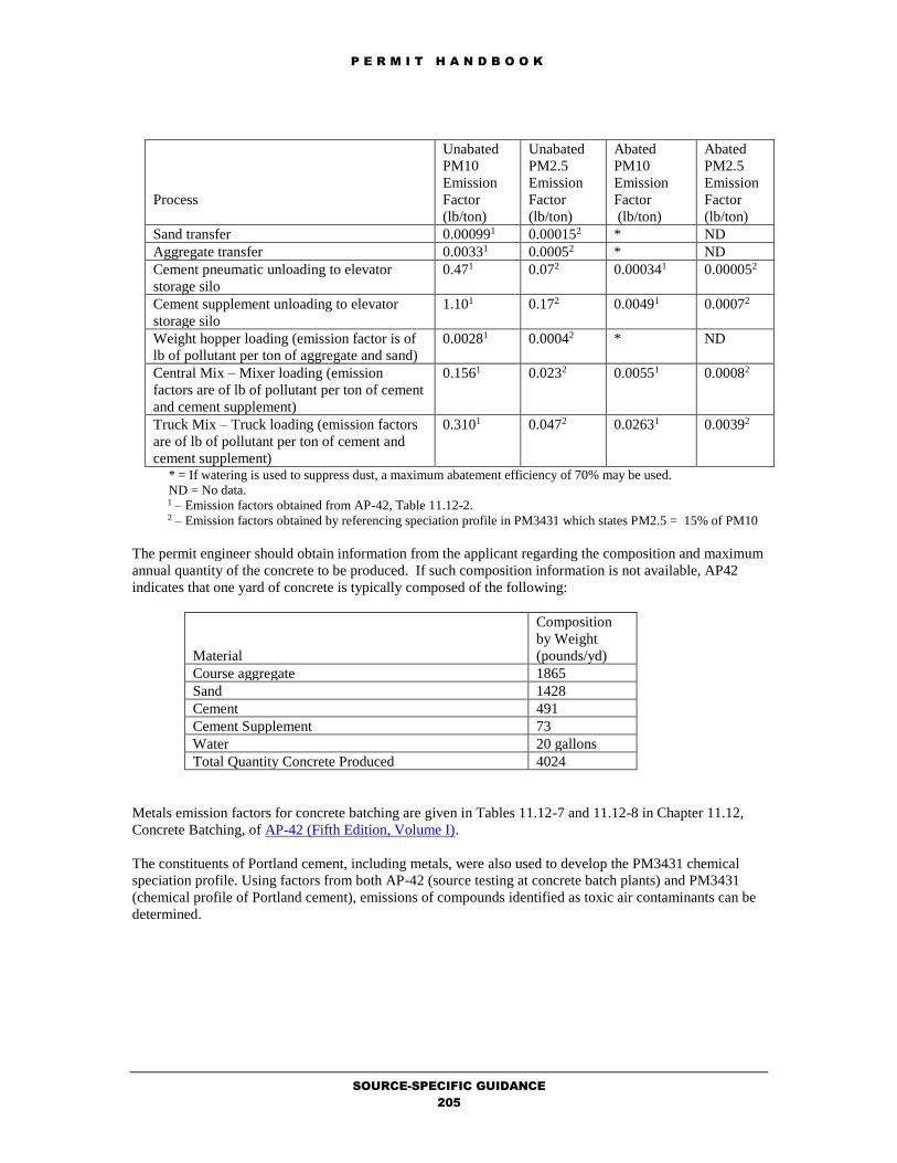
P E R M I T H A N D B O O K
SOURCE-SPECIFIC GUIDANCE
205
Process
Unabated
PM10
Emission
Factor
(lb/ton)
Unabated
PM2.5
Emission
Factor
(lb/ton)
Abated
PM10
Emission
Factor
(lb/ton)
Abated
PM2.5
Emission
Factor
(lb/ton)
Sand transfer 0.000991 0.000152 * ND
Aggregate transfer 0.00331 0.00052 * ND
Cement pneumatic unloading to elevator
storage silo
0.471 0.072 0.000341 0.000052
Cement supplement unloading to elevator
storage silo
1.101 0.172 0.00491 0.00072
Weight hopper loading (emission factor is of
lb of pollutant per ton of aggregate and sand)
0.00281 0.00042 * ND
Central Mix – Mixer loading (emission
factors are of lb of pollutant per ton of cement
and cement supplement)
0.1561 0.0232 0.00551 0.00082
Truck Mix – Truck loading (emission factors
are of lb of pollutant per ton of cement and
cement supplement)
0.3101 0.0472 0.02631 0.00392
* = If watering is used to suppress dust, a maximum abatement efficiency of 70% may be used.
ND = No data. 1 – Emission factors obtained from AP-42, Table 11.12-2. 2 – Emission factors obtained by referencing speciation profile in PM3431 which states PM2.5 = 15% of PM10
The permit engineer should obtain information from the applicant regarding the composition and maximum
annual quantity of the concrete to be produced. If such composition information is not available, AP42
indicates that one yard of concrete is typically composed of the following:
Material
Composition
by Weight
(pounds/yd)
Course aggregate 1865
Sand 1428
Cement 491
Cement Supplement 73
Water 20 gallons
Total Quantity Concrete Produced 4024
Metals emission factors for concrete batching are given in Tables 11.12-7 and 11.12-8 in Chapter 11.12,
Concrete Batching, of AP-42 (Fifth Edition, Volume I).
The constituents of Portland cement, including metals, were also used to develop the PM3431 chemical
speciation profile. Using factors from both AP-42 (source testing at concrete batch plants) and PM3431
(chemical profile of Portland cement), emissions of compounds identified as toxic air contaminants can be
determined.

P E R M I T H A N D B O O K
SOURCE-SPECIFIC GUIDANCE
206
Pollutant
Process
PM3431 Speciation
(lb-pollutant/ton-
cement)1
AP-42 Emission Factor
(lb-pollutant/ton-
material)2
Arsenic
Cement Silo Filling 1.68E-06
Cement Silo Filling (w/ fabric
filter)
4.24E-09
Cement Supplement Silo Filling ND
Cement Supplement Silo Filling
(w/ fabric filter)
1.00E-06
Central Mix Batching 8.38E-06
Central Mix Batching (w/ fabric
filter)
2.96E-07
Truck Loading 1.22E-05
Truck Loading (w/ fabric filter) 6.02E-07
Beryllium
Cement Silo Filling 1.79E-08
Cement Silo Filling (w/ fabric
filter)
4.86E-10
Cement Supplement Silo Filling ND
Cement Supplement Silo Filling
(w/ fabric filter)
9.04E-08
Central Mix Batching ND
Central Mix Batching (w/ fabric
filter)
ND
Truck Loading 2.44E-07
Truck Loading (w/ fabric filter) 1.04E-07
Cadmium
Cement Silo Filling 2.34E-07
Cement Silo Filling (w/ fabric
filter)
ND
Cement Supplement Silo Filling ND
Cement Supplement Silo Filling
(w/ fabric filter)
1.98E-10
Central Mix Batching 1.18E-10
Central Mix Batching (w/ fabric
filter)
7.10E-10
Truck Loading 3.42E-08
Truck Loading (w/ fabric filter) 9.06E-09
Chlorine All 0.4
Total
Chromium3
Cement Silo Filling 2.52E-07
Cement Silo Filling (w/ fabric
filter)
2.90E-08
Cement Supplement Silo Filling ND
Cement Supplement Silo Filling
(w/ fabric filter)
1.22E-06
Central Mix Batching 1.42E-06
Central Mix Batching (w/ fabric
filter)
1.27E-07
Truck Loading 1.14E-05
Truck Loading (w/ fabric filter) 4.10E-06

P E R M I T H A N D B O O K
SOURCE-SPECIFIC GUIDANCE
207
Pollutant
Process
PM3431 Speciation
(lb-pollutant/ton-
cement)1
AP-42 Emission Factor
(lb-pollutant/ton-
material)2
Lead
Cement Silo Filling 7.36E-07
Cement Silo Filling (w/ fabric
filter)
1.09E-08
Cement Supplement Silo Filling ND
Cement Supplement Silo Filling
(w/ fabric filter)
5.20E-07
Central Mix Batching 3.82E-07
Central Mix Batching (w/ fabric
filter)
3.66E-08
Truck Loading 3.62E-06
Truck Loading (w/ fabric filter) 1.53E-06
Manganese
All 2.4
Cement Silo Filling 2.02E-04
Cement Silo Filling (w/ fabric
filter)
1.17E-07
Cement Supplement Silo Filling ND
Cement Supplement Silo Filling
(w/ fabric filter)
2.56E-07
Central Mix Batching 6.12E-05
Central Mix Batching (w/ fabric
filter)
3.78E-06
Truck Loading 6.12E-05
Truck Loading (w/ fabric filter) 2.08E-05
Nickel
Cement Silo Filling 1.76E-05
Cement Silo Filling (w/ fabric
filter)
4.18E-08
Cement Supplement Silo Filling ND
Cement Supplement Silo Filling
(w/ fabric filter)
2.28E-06
Central Mix Batching 3.28E-06
Central Mix Batching (w/ fabric
filter)
2.48E-07
Truck Loading 1.19E-05
Truck Loading (w/ fabric filter) 4.78E-06
Selenium
Cement Silo Filling ND
Cement Silo Filling (w/ fabric
filter)
ND
Cement Supplement Silo Filling ND
Cement Supplement Silo Filling
(w/ fabric filter)
7.24E-08
Central Mix Batching ND
Central Mix Batching (w/ fabric
filter)
ND
Truck Loading 2.62E-06
Truck Loading (w/ fabric filter) 1.13E-07
Silica All ND4
Sulfate All 84.2 ND = No Data
1 – Emission factors obtained from chemical speciation in PM3431.
2 – Emission factors obtained from AP-42, Table 11.12-8.
3 – Data from EPA Region 9 suggests that Chromium(VI) is about 1/7 of Total Chromium.

P E R M I T H A N D B O O K
SOURCE-SPECIFIC GUIDANCE
208
4 – While PM3431 does list silica as a constituent, the amount of crystalline, respirable silica is undetermined.
Emissions from vehicle traffic on unpaved roads to and from the storage piles should also be accounted in
the emissions for the storage piles. An unpaved roads emission factor equation is provided in Chapter
13.2.2, Unpaved Roads of AP-42 (Fifth Edition, Volume I) for vehicles traveling on unpaved surfaces at
industrial sites:
E = k(s/12)a(W/3)b((365-P)/365)) lb/VMT [Equation 1a]
and for vehicles traveling on publicly accessible roads, dominated by light duty vehicles:
E = [k(s/12)a(S/30)d/(M/0.5)c – C]((365-P)/365)) lb/VMT [Equation 1b]
The following provides an explanation of the variables in the equation and the average values
recommended for use (only if actual more specific and precise values are not available), if the source-
specific values are not known:
E = Emission Factor (lb/VMT)
k = Particle size multiplier (dimensionless); PM10, k = 1.5 for Equation 1a, 1.8 for Equation 1.b
a = Empirical Constants; a = 0.9 for Equation 1a, 1 for Equation 1b
b = Empirical Constants; b = 0.45
c = Empirical Constants; c = 0.2 for Equation 1b
d = Empirical Constants; d = 0.5 for Equation 1b
s = Silt content of road surface (%); s = See Table 13.2.2-114 and use the mean value for the
applicable industry. (For example, for stone and gravel
processing s=4.8 for plant roads, 7.1 for material storage
areas.)
W = Mean vehicle weight (tons); W=146 tons for Equation 1a, 2 tons for Equation 1b
M = surface material moisture content (%); M = 6.5
S = Mean vehicle speed (mph); S = 24 for Equation 1a, 33 for Equation 1b
C = emission factor for 1980’s vehicle fleet exhaust, brake wear and tire wear; C = 0.0004715
P = Number of days with greater than, or equal to, 0.01 inches of precipitation per year; 7016
For example, at stone and gravel processing sources at concrete batch plants, the emission factors used for
unpaved roads are calculated as follows:
E1a = (1.5)(4.8/12)0.9(146/3)0.45(365-70/365)
E1a = 3.05 lb/VMT [for unpaved plant roads at stone and gravel processing]
E1a = (1.5)(7.1/12)0.9(146/3)0.45(365-70/365)
E1a = 4.34 lb/VMT [for unpaved material storage areas]
The permit engineer should determine which emission factor equation (1a or 1b) is most appropriate
depending on the unpaved surfaces or roads where the sources will be situated. The permit engineer should
also obtain information from the applicant regarding the maximum vehicle weight and miles traveled per
year by all vehicles involved on driving on the unpaved roads at the facility. If watering is used to suppress
dust, a maximum abatement efficiency of 70% may be used. If chemical dust suppressants are used, a
maximum abatement efficiency of 80% may be used17.
14 Chapter 13.2.2, Unpaved Roads of AP-42 (Fifth Edition, Volume I), pg. 3. 15 Chapter 13.2.2, Unpaved Roads of AP-42 (Fifth Edition, Volume I), pg. 6. 16 Chapter 13.2.2, Unpaved Roads of AP-42 (Fifth Edition, Volume I), pg. 9. 17 Chapter 13.2.2, Unpaved Roads of AP-42 (Fifth Edition, Volume I), pg. 13.

P E R M I T H A N D B O O K
SOURCE-SPECIFIC GUIDANCE
209
Emission factors for storage piles at concrete batch plants are taken from Chapter 13.2.4, Aggregate
Handling and Storage Piles, of AP-42 (Fifth Edition, Volume I). These emission factors include emissions
from drop operations into storage piles:
E = k(0.0032)(U/5)1.3/(M/2)1.4
The following provides an explanation of the variables in the equation and the mean values recommended
for use, if the source-specific values are not known:
E = Emission Factor (lb/ton)
k = Particle size multiplier (dimensionless); PM10, k = 0.35
U = mean wind speed (miles/hr); U = 8.2
M = material moisture content (%); M = 2.1
E = (0.35)(0.0032)(8.2/5)1.3/(2.1/2)1.4
E = 0.002 lb/ton [for storage piles]
For emissions from equipment traffic (truck, front-end loaders, dozer, etc.) traveling between or on piles, it
is recommended that the equation for vehicle traffic on unpaved surfaces be used (see Equation 1a). The
emissions from equipment traffic around the piles should be calculated using the same emission factors
noted previously for unpaved roads by including the VMT around these piles and including it in the total
estimated VMT on unpaved roads within the facility.
Emission factors for storage piles at concrete batch plants are taken from AP-42, Fourth Edition, Section
8.19, Table 8.19.1-1. These emission factors include emissions from loading into storage piles, equipment
traffic in storage pile area, and wind erosion. Assuming the 3.5 lb/acre/day emission is for TSP emissions
the wind blown PM10 emissions would be approximately 50% or:
EPM10 = 1.7 lb/acre/day
The permit engineer should obtain information from the applicant regarding the maximum area (in acres)
that the storage piles and the number of days per year that the storage piles will exist at the concrete batch
plant.
Furthermore, if railcars or ships are involved in the transportation of materials, then also the combustion
emissions from the use of these transport vehicles should also be calculated and included in the facilities
cumulative increase.
Applicable Requirements
District Rules and Regulations
In general, the particulate sources at concrete batch plants are subject to the operating standards of
Regulation 6-1. All but the transfer points of cement and cement supplement into the storage silos are
fugitive in nature. The storage silos are generally abated by a fabric filter or baghouse device. Fugitive
sources include the transfer of sand and aggregate, truck loading, mixer loading, vehicle traffic, and wind
erosion from sand and aggregate storage piles. The amount of fugitive emissions generated during the
transfer operations depend primarily on the surface moisture content of these materials. Types of controls
used may include water sprays, enclosures, and baghouse devices. With these controls of the equipment
and good maintenance and wetting of unpaved road surfaces, particulate emissions should comply with the
operating standards of Regulation 6-1. Permit conditions are imposed to ensure compliance with
Regulation 6-1.

P E R M I T H A N D B O O K
SOURCE-SPECIFIC GUIDANCE
210
Best Available Control Technology (BACT)
BACT for the particulate sources at concrete batch plants are specified in the BACT/TBACT Workbook.
The following are applicable BACT requirements for:
Concrete Batch Plant
- < 5 cubic yards per batch
- >= 5 cubic yards per batch
Inform the BACT Coordinator of updates to the BACT/TBACT Workbook.
California Environmental Quality Act (CEQA)
Permit applications which are reviewed following the specific procedures, fixed standards and objective
measurements set forth in this chapter (11.5) are classified as ministerial and will accordingly be exempt
from CEQA review per Regulation 2-1-311.
In addition to the above-mentioned source-specific applicable requirements, other requirements may also
be applicable depending on the facility, its application emissions, and its source location:
Offsets
Prevention of Significant Deterioration
School Notification
Risk Screening Analysis
Permit Conditions
Standardized conditions for concrete batch plants are available from the Permit Condition Guidance. Refer
to the Evaluation Report Template Guidance to obtain the Microsoft Word formatted permit conditions for
this source category.

P E R M I T H A N D B O O K
SOURCE-SPECIFIC GUIDANCE
211
11.6 CREMATORIES
by M.K. Carol Lee
October 23, 2018
Process Description
Cremation is the act of reducing a corpse by burning, generally in a crematorium furnace or crematory fire.
A multiple chamber incinerator is generally used to cremate human and pet animal remains. An incinerator
with two chambers, namely primary and secondary, is the most widely used type of cremator. The
secondary chamber is heated first by igniting the afterburner and heating to an operating temperature of at
or above 1500° F. A "cremation case charge" (human or animal remains enclosed in a wooden
casket/cardboard casket or a body bag) is introduced in the primary chamber, called a retort, and the retort
door is closed. The charge is placed on the hearth in a manner that provides for maximum exposure to the
flame of the primary burner. Control timers are set, and an opacity monitor and power switch are activated.
The low fire ignition burner in the primary chamber is activated. Within approximately 30 minutes, the
high fire cremation burner in the primary chamber begins a controlled cycling range of 1750 to 1800° F.
This cycling continues until the cremation process is complete. During the cremation process, a large part
of the body (especially the organs) and other soft tissue are vaporized and oxidized due to the heat, and the
gases are discharged through the exhaust system. All that remains after cremation are dry bone fragments
(mostly calcium phosphates and minor minerals). The approximate time for complete cremation is 2 hours,
which may vary depending on charge weight.
After the incineration is completed, the bone fragments are swept out of the retort and the operator uses a
pulverizer called a cremulator to process them into what are known as cremains which exhibit the
appearance of grains of sand and recognizable chips of very dry bone.
Completeness Determination
The following District forms should be completed and fees provided for cremators. Use the Completeness
Determination Checklist to verify completeness. Use the Data Form Guidance to ensure that the forms are
completed correctly. Use the Fee Calculation Guidance to ensure that the fees are calculated accurately.
1. Form 101-B (one for facility).
2. Form G (one per source).
3. Source Description: Crematory Retort with
Integral Afterburner
4. Process Code: 8011 (crematory retort)
Material Code: 791 (bodies - human) and
Usage Unit: tons
5. or Material Code: 498 (Animal carcasses)
and Usage Unit: pounds
6. Form C (one per Retort and Afterburner).
7. Form A (only if applicant chooses to control
emissions with abatement equipment other
than an afterburner in secondary chamber of
a crematory retort).
8. Form P (one per stack).
9. If Health Risk Screening is triggered, Form
HRSA (one per source).
10. Fees, calculated per Regulation 3 (Schedule
G-1 for incinerators - crematory).
11. Any emission data available for the
proposed crematory retort, or use standard
emission factors indicated in Emission
Calculations section.
Emission Calculations
Crematory retort can produce emissions of flyash, smoke, gases, and odor. Odor and visible emissions can
be objectionable to many people on aesthetic grounds. A poorly designed retort with inadequate
turbulence, temperatures, and residence time can result in the objectionable emissions. The visible and
odor emissions can best be controlled by good retort design. An afterburner in the secondary chamber of
the retort compensates for deficiencies, if any, in the design of the primary chamber to minimize air
contaminants.
Almost all crematory retorts use natural gas as the fuel to cremate "cremation case charge." A "cremation
case charge" is a body in a casket or a bag. As a result, the emission factors available for natural gas
combustion in AP-42 Chapter 1.4 (Tables 1.4-1 and 1.4-2) can be used to estimate particulate matter
(PM10), nitrogen oxides (NOx), carbon monoxide (CO), sulfur dioxide (SO2), and precursor organic

P E R M I T H A N D B O O K
SOURCE-SPECIFIC GUIDANCE
212
compounds (POC) emissions from the combustion of natural gas in the crematory retort. The emission
factors for natural gas combustion are as follows:
NATURAL GAS COMBUSTION EMISSION FACTORS18
Pollutant Emission Factor (lb/MM cu ft)
PM10 7.6
NOx 100
CO 84
SO2 0.6
POC (VOC, not including methane) 5.5
In addition to natural gas combustion, there are also emissions attributed to the combustion of the
casket and body. According to EPA’s FIRE Program19, the PM10 emission factor associated with the
combustion of body and the wrapping material is 8.5x10⁻² pounds per each body burned20. In
deriving the PM10 emission factor, the average weight per body incinerated was approximately 150
lbs (rounded up). In calculating the other criteria pollutants, the emission factors available for
medical waste incineration in AP-42 Chapter 2.3 (Table 2.3-1 and 2.3-2) can be used to estimate
NOx, CO, SO2, and POC emissions. In summary, the following are the emission factors for the
combustion of the body and its case:
BODY AND CASE COMBUSTION EMISSION FACTORS
Pollutant
Emission Factor
(lb/ton) – used in
human emissions
calculation
Emission Factor
(lb/body)21 –
used in animal
emissions
calculation
Reference
PM10 1.13 8.50E-02 FIRE
NOx 3.56 2.67E-01 AP-42 Table 2.3-1
CO 2.95 2.21E-01 AP-42 Table 2.3-1
SO2 2.17 1.63E-01 AP-42 Table 2.3-1
POC 0.299 2.24E-02 AP-42 Table 2.3-2
TOXICS
For toxic emissions, emissions factors for crematories from FIRE database were also obtained:
TOXICS EMISSION FACTORS22
Pollutant Emission Factor (lb/body)
Acetaldehyde23 1.3 E-04
Arsenic 3.0 E-05
Antimony 3.0 E-05
18 Emission factor is for uncontrolled natural gas boilers less than 100 MMBTU/hr. 19 The Factor Information REtrieval (FIRE) Data System is a database containing EPA's emission
estimation factors for criteria and hazardous air pollutants in an easy to use Windows program. 20 Standard Classification Code (SCC) = 31502101 for Crematoriums from Emissions Testing of a
Propane Fired Incinerator at a Crematorium, October 29, 1992. 21 The average weight of a body (including casing) is 150 lbs. 22 Except for mercury, formaldehyde and acetaldehyde, pollutant emission factors are from EPA’s
FIRE database for crematoriums (SCC = 31502101). 23 Formaldehyde and acetaldehyde emission factors are calculated based on the data in CARB’s Test
Report No. C-90-004, “Evaluation Test on Two Propane Fired Crematories Camellia Memorial Lawn
Cemetery”, October 29, 1992.

P E R M I T H A N D B O O K
SOURCE-SPECIFIC GUIDANCE
213
Pollutant Emission Factor (lb/body)
Beryllium 1.4 E-06
Cadmium 1.1 E-05
Chromium, hexavalent 1.4 E-05
Copper 2.7 E-05
Formaldehyde6 3.4 E-05
Hydrogen chloride 7.2 E-02
Hydrogen fluoride 6.6 E-04
Lead 6.6 E-05
Mercury24 3.4 E-03 (annual average);
1.3E-02 (acute)
Nickel 3.8 E-05
Selenium 4.4 E-05
Zinc 3.5 E-04
Chlorinated
dibenzodioxins and furans
(expressed as 2,3,7,8
TCDD equivalents)25
1.4 E-09
Polycyclic Aromatic
Hydrocarbons (PAHs)
[expressed as
benzo(a)pyrene
equivalent]26
4.9 E-08
A crematories spreadsheet has been developed with worksheets to calculate emissions from human and
animal cremations using all the emissions indicated above.
Applicable Requirements
District Rules and Regulations
In general, a permit is required for each crematory retort. The cremulator is exempt from permitting
requirements per Regulation 2-1-121.
Crematory retorts are subject to the operating standards of Regulation 6-1 and Regulation 8-2. The visible
and odor emissions can best be controlled by good retort design. The permit conditions for crematories
include parts which will ensure compliance with Regulation 6-1. The permit engineer calculated emissions
for POCs should be compared to the operating standards of Regulation 8-2 to determine compliance.
Best Available Control Technology (BACT)
BACT for the crematory retorts are specified in the BACT/TBACT Workbook. The following are
applicable BACT requirements for:
24 The mercury emission factors are from “Mercury Emissions from the Cremation of Human
Remains” September 24, 2012, by Jane Lundquist . This factor should only be applied for human
cremations. 25 Using the latest FIRE factors (dated 3/6/2008), the dioxin/furan emission factor was calculated
based on the equivalency factors in the 2003 OEHHEA risk assessment guidelines (see Note 1 of
Crematories spreadsheet). 26 Using the latest FIRE factors (dated 3/6/2008), the PAH emission factor was calculated based on
the equivalency factors in the 2003 OEHHEA risk assessment guidelines (see Note 2 of Crematories
spreadsheet).

P E R M I T H A N D B O O K
SOURCE-SPECIFIC GUIDANCE
214
Crematories
- Crematory
Inform the BACT Coordinator of updates to the BACT/TBACT Workbook.
California Environmental Quality Act (CEQA)
Permit applications which are reviewed following the specific procedures, fixed standards and objective
measurements set forth in this chapter (11.5) are classified as ministerial and will accordingly be exempt
from CEQA review per Regulation 2-1-311.
In addition to the above-mentioned source-specific applicable requirements, other requirements may also
be applicable depending on the facility, its application emissions, and its source location:
Offsets
Prevention of Significant Deterioration
School Notification
Risk Screening Analysis
Permit Conditions
Standardized conditions for human and animal crematories are available from the Permit Condition
Guidance. Refer to the Evaluation Report Template Guidance to obtain the Microsoft Word formatted
permit conditions for this source category.

P E R M I T H A N D B O O K
SOURCE-SPECIFIC GUIDANCE
215
11.7 CRUSHING AND GRINDING
by M.K. Carol Lee
October 23, 2018
Process Description
Crushing and grinding operations are performed typically at quarries. A thorough explanation of the
crushed stone processing and pulverized mineral processing is available from Chapter 11.19.2, Crushed
Stone Processing and Pulverized Mineral Processing of AP-42 (Fifth Edition, Volume I).
Crushing and grinding operations are generally made up a number of sources of air pollution which store,
convey, measure, and discharge its constituents. Per District policy, the following sources at the plants
shall be permitted:
Sand and Aggregate Storage Piles (grouped as one source if they are all in the same general area)
Storage Silos (each silo is a separate source)
Conveyors (grouped as one source if they are all in the same general area)
Crushers (each crusher is a separate source)
Screens (each screen is a separate source)
Completeness Determination
The following District forms should be completed and fees provided for crushing and grinding h plants.
Use the Completeness Determination Checklist to verify completeness. Use the Data Form Guidance to
ensure that the forms are completed correctly. Use the Fee Calculation Guidance to ensure that the fees are
calculated accurately. There is a Policy: Fees Associated with Concrete Batch Facilities and
Quarrying/Crushing Operations for the grouping of sources and the calculation of fees at concrete batch
plants and quarrying/crushing operations.
1. Form 101-B (one for facility).
2. Form G (one per source).
3. Process Diagram and Map of the Crushing
and Grinding Plant.
4. Form A for watering system (one per
facility)
5. Form A (one per device) for any particulate
abatement device (i.e., baghouse).
6. If Health Risk Screening is triggered, Form
HRSA (one per source).
7. Fees, calculated per Regulation 3 (Schedule
F for all sources except, crushers and
grinders, which is subject to Schedule G-1).
8. See the Emissions Calculations section for
additional information that should be
provided by the applicant regarding the
crushing and grinding plant.
Emission Calculations
Particulate matter, consisting primarily of cement and cement supplement dust but including some
aggregate and sand dust, is the primary pollutant of concern. In addition, there are emissions of metals that
are associated with this particulate matter. Particulate emission factors for crushing and grinding are given
in Table 11.19.2-2 in Chapter 11.19.2, Crushed Stone Processing and Pulverized Mineral Processing of AP-
42 (Fifth Edition, Volume I).
Crushing
Process
Unabated
PM10
Emission
Factor
(lb/ton)
Abated PM10
Emission
Factor
(lb/ton)
Tertiary Crushing 0.0024 0.00054
Fines Crushing 0.0150 0.0012
Screening 0.0087 0.00074
Fines Screening 0.072 0.0022
Conveyor Transfer Point 0.0011 4.6e-5
Drop Unloading 0.00010 *
* = If watering is used to suppress dust, a maximum abatement efficiency of 70% may be used.

P E R M I T H A N D B O O K
SOURCE-SPECIFIC GUIDANCE
216
The permit engineer should obtain information from the applicant regarding maximum annual quantity of
the stone to be crushed.
Emissions from vehicle traffic on unpaved roads to and from the storage piles should also be accounted in
the emissions for the storage piles. An unpaved roads emission factor equation is provided in Chapter
13.2.2, Unpaved Roads of AP-42 (Fifth Edition, Volume I) for vehicles traveling on unpaved surfaces at
industrial sites:
E = k(s/12)a(W/3)b((365-P)/365)) lb/VMT [Equation 1a]
and for vehicles traveling on publicly accessible roads, dominated by light duty vehicles:
E = [k(s/12)a(S/30)d/(M/0.5)c – C]((365-P)/365)) lb/VMT [Equation 1b]
The following provides an explanation of the variables in the equation and the average values
recommended for use (only if actual more specific and precise values are not available), if the source-
specific values are not known:
E = Emission Factor (lb/VMT)
k = Particle size multiplier (dimensionless); PM10, k = 1.5 for Equation 1a, 1.8 for Equation 1.b
a = Empirical Constants; a = 0.9 for Equation 1a, 1 for Equation 1b
b = Empirical Constants; b = 0.45
c = Empirical Constants; c = 0.2 for Equation 1b
d = Empirical Constants; d = 0.5 for Equation 1b
s = Silt content of road surface (%); s = See Table 13.2.2-127 and use the mean value for the
applicable industry. (For example, for stone and gravel
processing s=4.8 for plant roads, 7.1 for material storage
areas.)
W = Mean vehicle weight (tons); W=146 tons for Equation 1a, 2 tons for Equation 1b
M = surface material moisture content (%); M = 6.5
S = Mean vehicle speed (mph); S = 24 for Equation 1a, 33 for Equation 1b
C = emission factor for 1980’s vehicle fleet exhaust, brake wear and tire wear; C = 0.0004728
P = Number of days with greater than, or equal to, 0.01 inches of precipitation per year; 7029
For example, at stone and gravel processing sources, the emission factors used for unpaved roads are
calculated as follows:
E1a = (1.5)(4.8/12)0.9(146/3)0.45(365-70/365)
E1a = 3.05 lb/VMT [for unpaved plant roads at stone and gravel processing]
E1a = (1.5)(7.1/12)0.9(146/3)0.45(365-70/365)
E1a = 4.34 lb/VMT [for unpaved material storage areas]
The permit engineer should determine which emission factor equation (1a or 1b) is most appropriate
depending on the unpaved surfaces or roads where the sources will be situated. The permit engineer should
also obtain information from the applicant regarding the maximum vehicle weight and miles traveled per
year by all vehicles involved on driving on the unpaved roads at the facility. If watering is used to suppress
27 Chapter 13.2.2, Unpaved Roads of AP-42 (Fifth Edition, Volume I), pg. 3. 28 Chapter 13.2.2, Unpaved Roads of AP-42 (Fifth Edition, Volume I), pg. 6. 29 Chapter 13.2.2, Unpaved Roads of AP-42 (Fifth Edition, Volume I), pg. 9.

P E R M I T H A N D B O O K
SOURCE-SPECIFIC GUIDANCE
217
dust, a maximum abatement efficiency of 70% may be used. If chemical dust suppressants are used, a
maximum abatement efficiency of 80% may be used30.
Emission factors for storage piles at crushing and grinding plants are taken from Chapter 13.2.4, Aggregate
Handling and Storage Piles, of AP-42 (Fifth Edition, Volume I). These emission factors include emissions
from drop operations into storage piles:
E = k(0.0032)(U/5)1.3/(M/2)1.4
The following provides an explanation of the variables in the equation and the mean values recommended
for use, if the source-specific values are not known:
E = Emission Factor (lb/ton)
k = Particle size multiplier (dimensionless); PM10, k = 0.35
U = mean wind speed (miles/hr); U = 8.2
M = material moisture content (%); M = 2.1
E = (0.35)(0.0032)(8.2/5)1.3/(2.1/2)1.4
E = 0.002 lb/ton [for storage piles]
For emissions from equipment traffic (truck, front-end loaders, dozer, etc.) traveling between or on piles, it
is recommended that the equation for vehicle traffic on unpaved surfaces be used (see Equation 1a). The
emissions from equipment traffic around the piles should be calculated using the same emission factors
noted previously for unpaved roads by including the VMT around these piles and including it in the total
estimated VMT on unpaved roads within the facility.
Emission factors for wind erosion for storage piles at crushing and grinding plants may be taken from AP-
42, Fourth Edition, Section 8.19, Table 8.19.1-1. These emission factors include emissions from wind
erosion. Assuming the 3.5 lb/acre/day emission is for TSP emissions, the wind blown PM10 emissions
would be approximately 50% or:
EPM10 = 1.7 lb/acre/day
The permit engineer should obtain information from the applicant regarding the maximum area (in acres)
and throughput (in tons) that the storage piles will occupy and the number of days per year that the storage
piles will exist at the crushing and plant. If watering is used to suppress dust, a maximum abatement
efficiency of 70% may be used.
Furthermore, if railcars or ships are involved in the transportation of materials, then also the combustion
emissions from the use of these transport vehicles should also be calculated and included in the facilities
cumulative increase.
Applicable Requirements
District Rules and Regulations
In general, the particulate sources at crushing and grinding plants are subject to the operating standards of
Regulation 6. All but the transfer points of cement and cement supplement into the storage silos are
fugitive in nature. The storage silos are generally abated by a fabric filter or baghouse device. Fugitive
sources include the transfer of sand and aggregate, truck loading, mixer loading, vehicle traffic, and wind
erosion from sand and aggregate storage piles. The amount of fugitive emissions generated during the
transfer operations depend primarily on the surface moisture content of these materials. Types of controls
used may include water sprays, enclosures, and baghouse devices. With these controls of the equipment
and good maintenance and wetting of unpaved road surfaces, particulate emissions should comply with the
30 Chapter 13.2.2, Unpaved Roads of AP-42 (Fifth Edition, Volume I), pg. 13.

P E R M I T H A N D B O O K
SOURCE-SPECIFIC GUIDANCE
218
operating standards of Regulation 6. Permit conditions are imposed to ensure compliance with Regulation
6.
Best Available Control Technology (BACT)
BACT for the particulate sources at crushing and grinding plants are specified in the BACT/TBACT
Workbook. The following are applicable BACT requirements for:
Crushing and Grinding
- Rock - Aggregate Processing
- Solid Material Handling - Dry
- Solid Material Handling - Wet
- Solid Material Storage - Enclosed
- Solid Material Storage - Open
- Wood Processing Equipment
Inform the BACT Coordinator of updates to the BACT/TBACT Workbook.
New Source Performance Standards (NSPS)
Subpart OOO of the NSPS standard covers nonmetallic mineral processing, which includes regulations for
emissions from operating equipment that was manufactured, modified or reconstructed after August 31,
1983. Processing equipment regulated under Subpart OOO affecting the crushed stone, sand and gravel
industry includes crushers, grinding mills, screens, bucket elevators, bagging operations, storage bins,
enclosed truck and railcars and transfer points on belt conveyors.
Under Subpart OOO, aggregate facilities are required to conduct performance testing on stationary
equipment in accordance with EPA Reference Method 9. Method 9 is a visual emissions test that
determines opacity or the percentage of the light that is prevented from passing through a plume or fugitive
emission. Individuals performing the opacity readings are required to be trained and certified in accordance
with the method. EPA has set specific limits for the aggregates industry based on opacity readings
designated to various processing equipment ranging from 7-15 percent (%). Among the requirements of
Method 9 is determining the average of twenty-four readings over a six-minute period for a total of one
hour for each piece of equipment that falls under the purview of NSPS.
The permit engineer should determine whether the source is subject to Subpart OOO. An applicability flow
chart of Subpart OOO is available from the Texas Commission on Environmental Quality. If applicable,
the permit engineer should ensure that the facility has conducted or will be required to conduct the
performance testing required by the NSPS.
California Environmental Quality Act (CEQA)
Permit applications which are reviewed following the specific procedures, fixed standards and objective
measurements set forth in this chapter (11.7) are classified as ministerial and will accordingly be exempt
from CEQA review per Regulation 2-1-311.
In addition to the above-mentioned source-specific applicable requirements, other requirements may also
be applicable depending on the facility, its application emissions, and its source location:
Offsets
Prevention of Significant Deterioration
School Notification
Risk Screening Analysis
Permit Conditions
Standardized conditions for crushing and grinding equipment are available from the Permit Condition
Guidance. Refer to the Evaluation Report Template Guidance to obtain the Microsoft Word formatted
permit conditions for this source category.

P E R M I T H A N D B O O K
SOURCE-SPECIFIC GUIDANCE
219
11.9 MISCELLANEOUS ORGANIC OPERATIONS
by M.K. Carol Lee
October 23, 2018
Process Description
This chapter covers the permitting of miscellaneous operations that emit precursor organic compounds.
These are operations that are not specifically exempted under this rule and are not subject to any other rule
in Regulation 8 or 10. Regulation 8 - Policy: Regulation 8 Rule Applicability has been developed to clarify
how a source/operation that is exempt from the provisions of a specific Regulation 8 rule defaults to
Regulation 8, Rule 2 or 4.
Following are examples of operations that are subject to Regulation 8, Rule 2:
• Wastewater treatment facilities.
• Sludge dewatering.
• Paint mixers, excluding paint manufacturers.
• Solvent dispensing stations.
• Solvent stills.
• Paint filtering.
• Paint packaging.
• Adhesive manufacturing.
• Adhesive coating when the adhesive contains less than 20% solvent and no other rule in
Regulation 8 is applicable.
• Surface coating where no other rule in Regulation 8 is applicable and the solvent content of the
coating is less than 20%.
• Storage of organic liquids that is exempt from Regulation 8-5.
• Storage of organic liquids, which have a vapor pressure less than 0.5 psia.
• Combustion sources that are not subject to Regulation 10.
The following operations are exempt from Regulation 8, Rule 2:
• Natural gas operations, per Regulation 8-2-110.
• Preparation of food, per Regulation 8-2-111.
• Cold reduction equipment used in metal forming when certain cooling oils are used, per
Regulation 8-2-112.
• Blind changing, per Regulation 8-2-113.
• Cooling towers, per Regulation 8-2-114. (The permitting of Cooling Towers is described in
Permit Handbook Chapter # 11.4.)
• Railroad tank cars, per Regulation 8-2-114.
• Marine vessels, per Regulation 8-2-114.
• Crude oil production, per Regulation 8-2-114.
The following equipment is exempt from Regulation 8, Rule 2: per Regulation 8-2-115:
• Rubber or plastic presses, per Regulation 8-2-115.1.
• Certain plastic curing ovens, per Regulation 8-2-115.2.
• Certain vinyl plastisol ovens, per Regulation 8-2-115.3.
• Melting or applying of wax, per Regulation 8-2-115.4.
• Packaging of lubricants and greases, per Regulation 8-2-115.5.
• Manufacture of water emulsions of waxes, greases, or oils, per Regulation 8-2-115.6.
• Certain vacuum producing devices, per Regulation 8-2-115.7.
• Vitreous or porcelain enameling surfaces, per Regulation 8-2-115.8.
• Printing presses, except rotogravure presses, per Regulation 8-2-115.9.
• Bonding of lining to brake shoes, per Regulation 8-2-115.10.
• Equipment for hydraulic and hydrostatic testing, per Regulation 8-2-115.11.
• Ovens and furnaces used heat-treating and annealing metals, per Regulation 8-2-115.12.
• Oil quench tanks for tempering metals, per Regulation 8-2-115.13.

P E R M I T H A N D B O O K
SOURCE-SPECIFIC GUIDANCE
220
• Molten metal furnaces with a capacity of less than 450 in3, per Regulation 8-2-115.14.
• Space heating and heat transfer operations using gas fuel and rated at less than one million
BTU/hr., per Regulation 8-2-115.15.
• Steam cleaning equipment, per Regulation 8-2-115.16.
The following equipment or exhaust from the following equipment is exempt from Regulation 8, Rule 2 in
accordance with Regulation 8-2-116:
• Ovens for curing potting materials, per Regulation 8-2-116.1.
• Ovens for castings made with epoxy resins, per Regulation 8-2-116.2.
• Injection or compressions molding of plastics, per Regulation 8-2-116.3.
• Dipping operations for coating with oils, waxes, or greases, per Regulation 8-2-116.4.
• Dipping operations for coating with natural or synthetic resins which contain no organic solvents
• Unheated solvent dispensing containers, per Regulation 8-2-116.5.
• Ceramic firing kilns, if heated by natural gas, LPG, or electricity, per Regulation 8-2-115.6.
• Shell core and shell molding machines, per Regulation 8-2-115.7.
• Die casting machines, per Regulation 8-2-115.8.
• Laboratory equipment used exclusively for chemical or physical analyses and bench scale
laboratory equipment, per Regulation 8-2-115.9.
The following main categories of operations are subject to other rules in Regulation 8:
• Most surface coating operations.
• All general solvent and surface coating operations (Regulation 8-4).
• Most organic liquid storage (Regulation 8-5).
• Solvent cleaning (Regulation 8-16).
• Gasoline distribution (Regulation 8-7).
The contents of these rules should be examined to determine if a specific operation is exempt from
Regulation 8-2. Exemption from Regulation 8-2 or any rule in Regulation 8 is not an exemption from the
requirement for permits. A source or operation that emits air contaminants will require a permit unless
excluded by a provision in Regulation 1-110 or exempted by Regulation 2-1.
Completeness Determination
The following District forms should be completed and information and fees provided for coating
operations. Use the Completeness Determination Checklist to verify completeness. Use the Data Form
Guidance to ensure that the forms are completed correctly. Use the Fee Calculation Guidance to ensure
that the fees are calculated accurately.
1. Form P101-B (one for facility).
2. Form S (one per
source), if it is a miscellaneous coating or
solvent source.
3. Form G (one per
source), if it is NOT a miscellaneous coating
or solvent source.
4. If miscellaneous
organic operation exhausts to add-on
abatement device, Form A (one per device).
5. If Health Risk
Screening is triggered, Form HRSA (one per
source).
6. Fees, calculated per
Regulation 3 (Schedule E).
Emission Calculations
The emission factors for miscellaneous operations will depend on the type of source. Emissions factors
may be determined from AP-42, source testing, calculations, or using established emissions factors from
similar sources.
Applicable Requirements
The source must comply with Regulation 8, Rule 2. The miscellaneous operation shall not have emissions
of more than 15 lb/day with a concentration of more than 300 ppm total carbon into the atmosphere. The
source must exceed both conditions on a given day to be in violation of Regulation 8-2. Total carbon is

P E R M I T H A N D B O O K
SOURCE-SPECIFIC GUIDANCE
221
defined as the ppm of each compound multiplied by the number of carbon atoms in the molecule, excluding
1,1,1-trichloroethane, methylene chloride, methane, and chlorofluorocarbons.
Best Available Control Technology (BACT)
Because these types of operations are somewhat unique, BACT for miscellaneous organic operations is
currently NOT specified in the BACT/TBACT Workbook. As a result, any miscellaneous organic
operation, which triggers BACT, shall require a cost-effectiveness determination for add-on organic
abatement. Inform the BACT Coordinator of updates to the BACT/TBACT Workbook.
California Environmental Quality Act (CEQA)
Permit applications which are reviewed following the specific procedures, fixed standards and objective
measurements set forth in this chapter (11.9) are classified as ministerial and will accordingly be exempt
from CEQA review per Regulation 2-1-311. However, if BACT1, NSPS, or NESHAP requirements, then
CEQA review is also triggered because elements of discretion are required. The permit evaluator shall
follow the CEQA instructions specified in the Permit Evaluation Guidance in the permit handbook.
In addition to the above-mentioned source-specific applicable requirements, other requirements may also
be applicable depending on the facility, its application emissions, and its source location:
Offsets
Prevention of Significant Deterioration
School Notification
Risk Screening Analysis
Permit Conditions
Standardized conditions for miscellaneous organic operations are available from the Permit Condition
Guidance. Refer to the Evaluation Report Template Guidance to obtain the Microsoft Word formatted
permit conditions for this source category.

P E R M I T H A N D B O O K
SOURCE-SPECIFIC GUIDANCE
222
11.10 PORTABLE EQUIPMENT
by M.K. Carol Lee
October 23, 2018
Process Description
This chapter covers the permitting of portable equipment. District Regulation 2-1-220 defines portable
equipment as equipment that will not remain at any single location (facility boundaries) for more than
twelve consecutive months, will not be within 1000 feet of a school, will comply with Regulation 2-5, and
will not cause a public nuisance. Hence, any equipment, which meets these criteria, may be permitted as
portable. Portable diesel engines are covered in Permit Handbook Chapter 2.3.3.
Completeness Determination
The fees and District forms associated with the portable source are identical to those for like-kind
stationary source (refer to applicable permit handbook chapter for the specific source requirements). Use
the Completeness Determination Checklist to verify completeness. Use the Data Form Guidance to ensure
that the forms are completed correctly. For facility address, indicate the physical address where the
equipment will be operated initially, or the mailing address, if it is within the Bay Area counties that the
District covers. Use the Fee Calculation Guidance to ensure that the fees are calculated accurately.
Emission Calculations
The emission calculation procedures associated with the portable source are identical to those for the like-
kind stationary source (refer to applicable permit handbook chapter for specific source requirements).
Applicable Requirements
District Rules and Regulations
The District rules and regulations associated with the portable source are identical to those for the like-kind
stationary source (refer to applicable permit handbook chapter for specific source requirements). In
addition, the source must meet the criteria of portability set forth in District Regulation 2-1-220.
California Environmental Quality Act (CEQA)
Permit applications which are reviewed following the specific procedures, fixed standards and objective
measurements set forth in this chapter (11.10) are classified as ministerial and will accordingly be exempt
from CEQA review per Regulation 2-1-311.
In addition to the above-mentioned source-specific applicable requirements, other requirements may also
be applicable depending on the facility, its application emissions, and its source location:
Offsets
Prevention of Significant Deterioration
Risk Screening Analysis
Permit Conditions
Standardized conditions for portable equipment are available from the Permit Condition Guidance.
These conditions should be included with the standardized conditions for the like-kind stationary source.
Refer to the Evaluation Report Template Guidance to obtain the Microsoft Word formatted permit
conditions for this source category.

P E R M I T H A N D B O O K
SOURCE-SPECIFIC GUIDANCE
223
11.11 POLYESTER RESIN MANUFACTURING
by M.K. Carol Lee
October 23, 2018
Process Description
This chapter covers the permitting of resin manufacturing. A resin is defined as a solid or semi-solid, water
insoluble, organic material with little or no tendency to crystallize. Resins may be used as the basic
components of plastics and as components of surface coating formulations. Resins are generally produced
by combining various monomers, solvents, oils, catalysts, and other materials in batch or continuous
reactors. Generally, a District permit is required for each reactor, thinning tank, and/or blending tank,
which are defined in Regulation 8-36. However, for small polyester resin storage (< 600 gallon capacity),
grouping of tanks may be allowed, per Grouping Resin Storage Tanks at Fiberglass Operations . If the
facility has organic liquid storage tanks, then the permit handbook chapter for Organic Liquid Storage
Tanks should also be referenced.
Chapter 6.6.3 Polystyrene, of AP-42 (Fifth Edition, Volume I) provides a detailed description of how resins
are manufactured.
Completeness Determination
The following District forms should be completed and fees provided for polyester resin manufacturing.
Use the Completeness Determination Checklist to verify completeness. Use the Data Form Guidance to
ensure that the forms are completed correctly. Use the Fee Calculation Guidance to ensure that the fees are
calculated accurately.
1. Form 101-B (one for facility).
2. Form G (one form for each reactor, thinning
tank, and/or blending tank).
3. Form A (one per device).
4. Fees, calculated per Regulation 3 (Schedule
F ).
Emission Calculations
According to EPA’s FIRE Program31, the following are the emission factors for resin manufacturing:
SCC Code
Description
Pollutant
Emission Factor
(lb/ton)
3-01-018-17 General* POC 1.07 E 01
3-01-018-19 Solvent Recovery POC 3.20 E 00
3-01-018-21 Extruding/Pelletizing/Conveying/Storage POC 3.00 E-01
3-01-018-27 Polyamide Resins NOx 1.00 E 00
3-01-018-32 Urea-Formaldehyde Resins POC 1.47 E 01
3-01-018-42 Melamine Resin POC 5.00 E 01
3-01-018-47 Epoxy Resin POC 5.10 E 00
3-01-018-49 Acrylonitrile-Butadiene-Styrene (ABS) POC 6.00 E 01
3-01-018-70 Reactor (Polyester Resins) POC 5.00 E 01
3-01-018-80 Reactor (Polyurethane) POC 5.20 E 01
3-01-018-92 Separation Process POC 2.00 E 00
* This factor may be used to calculate total emissions from a polystyrene resin production plant.
The following equation can be used to calculate emission rates:
EPollutant = U(EF)
where,
EPollutant = emissions of pollutant (lb/yr)
31 The Factor Information REtrieval (FIRE) Data System is a database containing EPA's emission
estimation factors for criteria and hazardous air pollutants in an easy to use Windows program.

P E R M I T H A N D B O O K
SOURCE-SPECIFIC GUIDANCE
224
U = throughput (tons/yr)
EF = emission factor (lb/ton)
TOXICS
According to EPA’s FIRE Program32, the following are the toxics emission factors for resin
manufacturing:
SCC Code
Description
Pollutant Emission Factor
(lb/ton)
3-01-018-19 Solvent Recovery Styrene 1.45 E-01
3-01-018-21 Extruding/Pelletizing/Conveying/Storage Styrene 2.463 E-01
3-01-018-32 Urea-Formaldehyde Resins Formaldehyde 3.00 E-01
3-01-018-49 Acrylonitrile-Butadiene-Styrene (ABS) Styrene 2.78 E 00
The following equation can be used to calculate emission rates:
EPollutant = U(EF)
where,
EPollutant = emissions of pollutant (lb/yr)
U = throughput (tons/yr)
EF = emission factor (lb/ton)
Applicable Requirements
District Rules and Regulations
Resin manufacturing is subject to the requirements of Regulation 8, Rule 36 (Resin Manufacturing
Operations). Particulate Matter and Visible Emissions Standards).
California Environmental Quality Act (CEQA)
Permit applications which are reviewed following the specific procedures, fixed standards and objective
measurements set forth in this chapter (11.13) are classified as ministerial and will accordingly be exempt
from CEQA review per Regulation 2-1-311.
In addition to the above-mentioned source-specific applicable requirements, other requirements may also
be applicable depending on the facility, its application emissions, and its source location:
Offsets
Prevention of Significant Deterioration
Risk Screening Analysis
Permit Conditions
Standardized conditions for polyester resin manufacturing are available from the Permit Condition
Guidance. Refer to the Evaluation Report Template Guidance to obtain the Microsoft Word formatted
permit conditions for this source category.
32 The Factor Information REtrieval (FIRE) Data System is a database containing EPA's emission
estimation factors for criteria and hazardous air pollutants in an easy to use Windows program.

P E R M I T H A N D B O O K
SOURCE-SPECIFIC GUIDANCE
225
11.12 POLYESTER RESIN OPERATIONS
Originally written by Barry Young and Matthew Powers
Reformatted by M.K. Carol Lee
October 23, 2018
This permit handbook chapter describes the permitting procedures for the manufacturing of products using
polyester resins. Regulation 8, Rule 50 limits organic compound emissions from polyester resin
operations. Section 8-50-214 defines polyester resin operations as "methods used for the production or
rework of product by mixing, pouring, hand laying-up, impregnating, injecting, forming, spraying, and/or
curing unsaturated polyester materials with fiberglass, fillers, or any other reinforcement materials and
associated clean-up."
The first section of this chapter describes the types of polyester resin operations that may be encountered,
the process description, and the air emissions associated with polyester resin operations. The next three
sections discuss Bay Area Air Quality Management District permit requirements for this equipment and
items necessary for a permit application. The sixth section is an engineering evaluation template which
includes typical equipment/process descriptions, sample emission calculations, applicable regulatory
requirements, applicable District policies, and sample permit conditions.
Some of the information presented in the Process Description and Evaluation sections was obtained from
the following sources: EPA AP-42; The Minnesota Technical Assistance Program (MnTAP); EPA's
National Risk Management Research Laboratory; and The Air Pollution Engineering Manual. A complete
reference list is included at the end of this section.
Process Description
A growing number of products are fabricated from liquid polyester resin reinforced with glass fibers and
extended with various inorganic filler materials such as calcium carbonate, talc, mica, or small glass
spheres. These composite materials are often referred to as fiberglass reinforced plastic (FRP), or simply
"fiberglass". In some processes, resin products are fabricated without fibers, an example are the synthetic
marble fabricators. The polyester resin/fiberglass industry consists of many small facilities (such as boat
repair and small contract firms) and relatively few large firms that consume the major fraction of the total
resin.
The major product using resins with fillers, but no reinforcing fibers is the synthetic marble used in
manufacturing bathroom countertops, sinks, and related items. Other applications of non reinforced resin
plastics include automobile body filler, bowling balls and coatings. Fiber reinforced plastics products have
a wide range of application in industry, transportation, home and recreation. Industrial uses include storage
tanks, skylights, electrical equipment, ducting, pipes, machine components, and corrosion resistant
structural and process equipment. In transportation, automobile and aircraft applications are increasing
rapidly. Home and recreational items include bathroom tubs and showers, boats (building and repair),
surfboards, snowboards and skis, helmets, swimming pools and hot tubs, and a variety of sporting goods. In order to be used in the fabrication of products, the liquid resin must be mixed with a catalyst to initiate
polymerization into a solid thermoset. Catalyst concentrations generally range from 1 to 2 percent by
original weight of resin; within certain limits, the higher the catalyst concentration, the faster the cross-
linking reaction proceeds. Common catalysts are organic peroxides, typically methyl ethyl ketone peroxide
(MEKP). Resins may contain inhibitors, to avoid self-curing during resin storage, and promoters, to allow
polymerization to occur at lower temperatures.
Non-Reinforced Polyester Resins Synthetic marble casting, a large segment of the resin products industry, involves production of bathroom
sinks, vanity tops, bathtubs and accessories using filled resins that have the look of natural marble. No
reinforcing fibers are used in these products. Pigmented or clear gel coat can either be applied to the mold
itself or sprayed onto the product after casting to simulate the look of natural polished marble. Marble
casting can be an open mold process or it can be considered a semi-closed process if cast parts are removed
from a closed mold for subsequent gel coat spraying.

P E R M I T H A N D B O O K
SOURCE-SPECIFIC GUIDANCE
226
The polyester resin used in synthetic marble casting usually has higher viscosity and lower monomer levels
than the resins used for laminating and gel coats. Fillers and colorants are mixed with the resin in large
vats. To achieve the marbled effect, the colorants are often hand stirred. The mixed resin is then hand
poured into partially closed molds. The resin is cured at room temperature and, after curing, the mold is
removed. Gel coats may also be used, in which case, they are applied to the mold surface before pouring in
the resin. Gel coats are highly pigmented unsaturated polyester resins that provide a smooth, colored
surface that gives the appearance of a painted part. Sources of emissions include equipment leaks, resin
storage tanks, process operations, and transfer and handling operations. The major sources of process
operation emissions are the gel coat area and casting areas, where resin is mixed and poured into molds.
Reinforced Polyester Resins Reinforced plastics products are fabricated using any of several processes, depending on their size, shape
and other desired physical characteristics. The principle molding processes are open molding and closed
molding. The primary types of open molding fabrication processes include spray lay-up (resin spray-up),
hand lay-up, continuous lamination and pultrusion. Closed molding processes are primarily represented by
bag molding. Process descriptions for these molding processes are given below.
Open Molding Most open mold fabricators use similar processes to produce products with varying composition, sizes, and
shapes. For products with a smooth, durable surface, a smooth and highly polished mold is required. For
many products, a catalyzed gel coat is applied as the initial step. The resins are generally either hand rolled
or sprayed into the fiberglass reinforcement. Some hand rolling is essential even when the resin is sprayed,
for removing voids and ensuring proper compaction of resin and reinforcing material. Most open mold
fabrication facilities consist of one or more open production areas. In these open areas, a large number of
exhaust fan outlets are provided.
Spray Lay-up (Resin Spray-Up) Spray lay-up is an open mold process that uses mechanical spraying and chopping equipment for depositing
the resin and glass reinforcement. Chopping equipment consists of a spray gun attachment which chops
glass fiber into predetermined lengths and projects it to merge with the resin mix stream. This causes the
resin and chopped glass to be deposited simultaneously to the desired layer thickness on the mold surface
(or on the gel coat that was applied to the mold). This process allows a greater production rate and more
uniform parts than does hand lay-up, and often uses more complex molds. In spray lay-up, the mold defines the shape of the outer surface, and the mold itself is usually made of
reinforced plastic. The mold is first coated with a wax to ensure removal after curing. A layer of gel coat is
then sprayed on to the mold to form the outermost surface of the products. The gel coat is allowed to cure
for several hours but remains tacky so subsequent resin layers adhere better.
The polyester resin is applied with a spray gun that has a glass chopper attachment. Layers are built up and
rolled out on the mold as necessary to form the part. The spray gun has separate resin and catalyst streams
which mix as they exit the gun. However, compared to hand lay-up, more resin is typically used to produce
similar parts by spray lay-up because of the inevitable over spray of resin during application.
Air spray guns require a large volume of air flow at high pressures. This provides good control over spray
patterns; however, this type of spraying contributes to excessive fogging, over spray, and bounce back,
resulting in increased emissions and material loss. To reduce styrene emissions, air-assisted airless spray
guns can be used to apply gel coats and resins. Because high pressure is not needed at the nozzle, air-
assisted airless spraying results in lower emissions and less material loss. Polyester resins designed for use
in spray lay-up are promoted for cure at room temperature and usually are catalyzed with a liquid peroxide
such as MEKP.
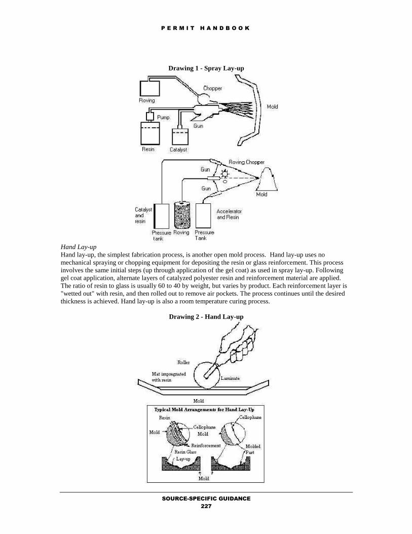
P E R M I T H A N D B O O K
SOURCE-SPECIFIC GUIDANCE
227
Drawing 1 - Spray Lay-up
Hand Lay-up Hand lay-up, the simplest fabrication process, is another open mold process. Hand lay-up uses no
mechanical spraying or chopping equipment for depositing the resin or glass reinforcement. This process
involves the same initial steps (up through application of the gel coat) as used in spray lay-up. Following
gel coat application, alternate layers of catalyzed polyester resin and reinforcement material are applied.
The ratio of resin to glass is usually 60 to 40 by weight, but varies by product. Each reinforcement layer is
"wetted out" with resin, and then rolled out to remove air pockets. The process continues until the desired
thickness is achieved. Hand lay-up is also a room temperature curing process.
Drawing 2 - Hand Lay-up

P E R M I T H A N D B O O K
SOURCE-SPECIFIC GUIDANCE
228
Continuous Lamination (Flow Coater With Chop) Continuous Lamination of reinforced plastics materials involves impregnating various reinforcements with
resins on an in-line conveyor. The resulting laminate is cured and trimmed as it passes through the various
conveyor zones. In this process, the resin mix is metered onto a bottom carrier film, using a blade to
control thickness. This film, which defines the panel's surface, is generally polyester, cellophane or nylon,
and may have a smooth, embossed or matte surface. Methyl methacrylate is sometimes used as the cross-
linking agent, either alone or in combination with styrene, to increase strength and weather resistance.
Chopped glass fibers free-fall into the resin mix and are allowed to saturate with resin, or "wet out". A
second carrier film is applied to the top of the panel before subsequent forming and curing. The cured
panel is then stripped of its films, trimmed, and cut to the desired length. Principal products include
translucent industrial skylights, and greenhouse panels, wall and ceiling liners for food areas, garage doors
and cooling tower louvers.
Drawing 3 - Continuous Lamination
Pultrusion Pultrusion, which can be thought of as extrusion by pulling, is used to produce continuous cross-sectional
lineals similar to those made by extruding metals such as aluminum. Reinforcing fibers are pulled through
a liquid resin mix bath and into a long machined steel die, where heat initiates an exothermic reaction to
polymerize the thermosetting resin matrix. The composite profile emerges from the die as a hot, constant
cross-sectional that cools sufficiently to be fed into a clamping and pulling mechanism. The product can
then be cut to desired lengths. Example products include electrical insulation materials, ladders, walkway
gratings, structural supports, and rods and antennas.

P E R M I T H A N D B O O K
SOURCE-SPECIFIC GUIDANCE
229
Drawing 4 - Pultrusion
Closed Molding Closed, such as compression or injection, molding operations involve the use of two matched dies to define
the entire outer surface of the part. When closed and filled with a resin mix, the matched die mold is
subjected to heat and pressure to cure the plastic. For the most durable production configuration, hardened
metal dies are used (matched metal molding). Another closed molding process is vacuum or pressure bag
molding. The range of closed molded parts includes tool and appliance housings, cookware, brackets and
other small parts, and automobile body and electrical components.
Bag Molding Bag molding is best used to produce an intermediate volume of small to mid-size components such as seats,
boat hatches, boat deck structures, and other items with shallow draft molds. Bag molding is conducted in
sealed molds at room temperature. The process is initiated with gel coat applied to the surface of the mold.
Glass reinforcing fibers and other materials are carefully cut to fit the mold and placed over it. Catalyzed
resin is sprayed, pumped or poured over the lay-up. Once the lay-up materials are in place, the exposed area
is covered with special layers of plastic which are sealed to the edges of the mold.
The bag molding process uses a bag or flexible membrane to apply pressure during molding; usually in
conjunction with an autoclave, a device which uses superheated steam to create pressure. A reinforced
laminate is layed-up by hand or sprayed and pressure is applied by drawing a vacuum under a cellophane,
vinyl, or nylon bag covering it. This assembly is then heated under pressure in an autoclave. The use of bag
molding allows the final product to have a higher fiberglass to resin ratio.
Spraying Operations Regulation 8, Rule 50, Section 302 requires the use of high transfer efficiency spray equipment. It requires
the use of one of the following: airless spray, air-assisted airless spray, electrostatic spray, or high-volume,
low-pressure spray.
The four basic types of coating spray application methods are air-atomized spray, airless spray, electrostatic
spray, and high-volume, low-pressure spray. Typically, coatings are sprayed in a spray booth to protect the
coated surface from dirt and to provide a well-ventilated area that protects workers from solvent vapors.
Air-atomized spray guns use compressed air to atomize the coating into tiny droplets and to spray the
coating onto the surface of the article to be coated. Note that air-atomized spray guns are prohibited per

P E R M I T H A N D B O O K
SOURCE-SPECIFIC GUIDANCE
230
section 302. The transfer efficiency for spray guns varies based on the configuration of the surface being
coated, the skill of the operator, and the type of spray gun being used. In airless spray coating, the coating is atomized without air as it is forced through specially designed
nozzles at pressures of 17 to 14MPa (1000-2000 psi). Electrostatic spraying involves the use of an
electrical transformer capable of delivering up to 60,000+ volts to create an electrical potential between the
coating particles and the surface to be coated. These charged coating particles are thus electrically attracted
to the surface, increasing the transfer efficiency over that of the nonelectrostatic air-atomized and airless
spray guns.
Another type of coating spray equipment is the high-volume, low-pressure or turbine spray gun. In this
system, a turbine is used to generate and deliver atomizing air. The turbine draws in filtered air, which is
driven through several stages at up to 10,500 rpm. The result is a high volume of warm, dry, atomizing air
that is delivered to the spray gun at less than 7 psi. This low-pressure gives greater control of the spray,
with less over spray because of the absence of the blasting effect common with high pressure systems.
Completeness Determination
The following District forms should be completed and fees provided for polyester resin manufacturing.
Use the Completeness Determination Checklist to verify completeness. Use the Data Form Guidance to
ensure that the forms are completed correctly. Use the Fee Calculation Guidance to ensure that the fees are
calculated accurately.
1. Form 101-B (one for facility).
2. Form S (one per source for each molding or spraying operation).
3. Fees, calculated per Regulation 3 (Schedule E).
Emission Calculations Sources of Emissions The only emissions of any significance from this source category are organic compounds. Organic vapors
consisting of volatile organic compounds (VOC) are emitted from fresh resin surfaces during the
fabrication process and from the use of solvents (usually acetone) for cleanup of hands, tools, molds and
spraying equipment. Cleaning solvent emissions can account for a significant portion of the total plant
VOC emissions. There may also be some release of particulate emissions from automatic fiber chopping
equipment, but these emissions have not yet been quantified.
Organic emissions from polyester resin/fiberglass fabrication processes occur when the cross-linking agent
(monomer) contained in the liquid resin evaporates into the air during resin application curing. Styrene,
methyl methacrylate and vinyl toulene are three of the principle monomers used in cross linking agents.
Styrene is by far the most common. Other chemical components of resins are emitted only at trace levels,
because they not only have low vapor pressures but are also substantially converted to polymers. Since emissions result from evaporation of monomer from the uncured resin, they depend upon the amount
of resin surface exposed to the air and the time of exposure. Thus, the potential for emissions varies with
the manner in which the resin is mixed, applied, handled and cured. These factors vary among the different
fabrication processes. For example, the spray lay-up process has the highest potential for VOC emissions
because the atomization of resin into spray creates an extremely large surface area from which volatile
monomer can evaporate.
For continuous lamination, exposure of the resin surface to air at the impregnation table is a source of
styrene emissions. In addition, the ovens and the final sawing operations release some uncured resin to the
atmosphere. The emissions from pultrusion operations are assumed to be the same as continuous
lamination.
By contrast, the emission potential in synthetic marble casting and closed molding operations is
considerably lower, because of the lower monomer content in the casting resins (30 to 38%, versus about
43%) and of the enclosed nature of these moldings. It has been found that styrene evaporation increases
with increasing gel time, wind speed and ambient temperature, and that increasing the hand rolling time on
a hand lay-up or spray-up results in significant styrene losses. Thus, production changes that lessen the
exposure of fresh resin surfaces to the air should be effective in reducing these evaporation losses.

P E R M I T H A N D B O O K
SOURCE-SPECIFIC GUIDANCE
231
Emission Reduction Strategies Styrene monomer is a significant source of VOCs from most polyester resin processes. Emissions from
open-mold processes tend to be the highest because of the spray-up technique used to apply the resin and
the large surface area of the part that is exposed during the curing. Operations located in California are
faced with some of the toughest air quality standards in the country. In response to the needs of this area,
resin manufacturers have developed low-organic emission resins. These products fall into the following
categories: 1. Vapor Suppressed Resins,
2. Benzoyl Peroxide (BPO)-Catalyzed Resins, and Low Styrene Resins
Vapor Suppressed Resins These resins contain a wax-like additive that migrates to the surface of the laminate during the cure step,
forming a barrier that inhibits the release of styrene. Vapor suppressant resins may reduce styrene
emissions by 30 to 50 percent during curing. These resins have had limited acceptance because the waxy
additive has the potential to inhibit the bonding of subsequent layers. The resins form a wax layer during
curing which must be thoroughly removed between each laminate application to ensure interlaminate
bonding. If maximum strength is not required, reducing the curing time between laminate applications can
partially address the wax layer buildup problem. Because of the difficulty in removing the wax layer, vapor
suppressant resins are only suitable for selected applications. However, the bond strength can be improved
by lightly sanding the surface of cure parts prior to applying the next laminate layer.
A 1982 California study found that vapor suppressed resins were used for 26 percent of resin and gel coat
application. Vapor suppressants are typically paraffin waxes that reduce styrene emissions by migrating to
the surface and reducing volatilization of styrene. In laminating resins, the vapor suppressant content can
range from 0.3 to 0.6 percent by weight.
Other vapor suppressants in use are thermoplastics and fatty acid esters. Other ways to reduce styrene
emissions would be to change from open to closed molding, reduce rollout times, and in general improve
housekeeping. In addition, the amount of polyester resin used can be reduced by redesigning products,
adding more fillers, and improving spray gun efficiency. Reformulation of resin could also be used to
reduce the monomer content in the resin.
BPO-Catalyzed Resins and Low-Styrene Resins The Minnesota Technical Assistance Program (MnTAP) recently conducted a study of low-styrene
emissions resins that focused on evaluating resins formulated with lower amounts of styrene (below 38%)
and resins catalyzed with BPO. The following general characteristics were observed: 1. Styrene emissions were reduced from 45 to 25%.
2. Substitutes were easily incorporated into existing processes.
3. Required minimal changes to spray equipment.
4. Economics of the substitution were favorable. For more details see the MnTAP website http://mntap.umn.edu/fiber/75-FRPemissions.htm .
The use of low styrene resins (35 percent styrene versus 43 percent) can potentially reduce total styrene
emission by 20 percent from resin application and curing. Problems with application may occur as viscosity
increases, and curing problems may result in structural defects. By improving the transfer efficiencies of
the spray guns used to apply gel coat and resin, styrene emissions due to over spray can be reduced to 42
percent for gel coat and 33 percent for resin spray lay-up.
The use of low vapor pressure solvents such as Dibasic Ester (DBE) can reduce the amount of clean up
solvent needed due to the reduction in evaporation volumes.
Add-on Controls In lieu of using complying resins, polyester resin operators can use add-on emission control devices. Four
emission control devices were evaluated for use at polyester resin operations: incineration; adsorption;
absorption; and condensation. These control technologies have been demonstrated to be highly effective in

P E R M I T H A N D B O O K
SOURCE-SPECIFIC GUIDANCE
232
reducing volatile organic emissions when exhaust gas concentrations are relatively high. However, exhaust
concentrations from polyester resin operations are typically less that 1000 ppm which make these control
technologies less effective and most likely not cost-effective. Each of the four technologies are defined
below.
Adsorption Adsorption is the condensation of a gaseous substance on a solid surface. When adsorption is used in
control devices for air pollution, it is the removal of pollutants from a gas stream by attachment of the
pollutants to a solid surface. Adsorption with carbon is a popular type of air pollution control of VOCs and
odors.
Absorption Absorption, or scrubbing, is a process where a soluble component of a gas mixture (absorbate) is removed
from the gas by dissolving it in a liquid (absorbent). In absorption, a gas can be absorbed by simply being
dissolved within a liquid, or it may be chemically reacted with the absorbing liquid. The liquid used to do
the absorbing is relatively nonvolatile.
Absorption is different from adsorption in that absorption involves collecting a pollutant (or gas vapor) by
passing it from a liquid surface throughout the liquid phase. In adsorption, the pollutant collects on a solid
surface and not within the solid phase. The pollutant may diffuse into the pores of the solid, but not within
its chemical structure. Furthermore, absorption involves removing a gas or a vapor by dissolving it into a
liquid while adsorption involves removing a substance by attaching it to a solid surface.
Condensation Condensation is the process of changing a gaseous substance into a liquid. Condensation can be applied
into an air stream contaminated with VOCs by condensing volatile compounds in a waste stream and
removing them. Condensation operations allow valuable solvents to be recovered while providing air
pollution control.
Incineration Incineration or oxidation involves destroying VOCs through the use of high temperatures from combustion
to oxidize pollutants. Incinerators or oxidizers for the destruction of VOCs from processes are often used
when it is not economical to recover solvents.
Emission Factors and Estimates Resin Storage Tank Emissions Styrene can be emitted during storage and transfer of the polyester resin and from the lamination area.
Resin is typically stored in outdoor temperature-controlled tanks and transferred to 55-gallon drums for
spray application. Emissions from these sources are expected to be small compared to the process
emissions. As discussed previously, styrene emissions occur during gel coat and resin application and from
resin curing. Gel coats are typically sprayed on and the resins are applied either by hand or spray lay-up. Storage Emissions Other possible sources of styrene emissions are storage tank losses and handling losses
that occur during product loading into drums, tank trucks, tank cars, barges, or ships. Styrene production
plants typically have from 2 to 12 small, fixed-roof monomer storage tanks. Storage tank losses are either
working losses that occur while filling the tank, or breathing losses due to expansion from temperature
changes. Both can be estimated using equations for storage tank emissions given in the U. S.
Environmental Protection Agency’s "Estimating Air Toxic Emissions from Organic Liquid Storage Tanks"
report. In the absence of specific data on the storage tank, two emission factors were identified in the
literature. Shown in Table 1, both are for uncontrolled emissions. No facilities are known to currently
control emissions with floating roof tanks or incineration, although several use condensing units to recover
styrene.
TABLE 1. STYRENE STORAGE EMISSION FACTORS
Emission Source Estimated Emission Factor

P E R M I T H A N D B O O K
SOURCE-SPECIFIC GUIDANCE
233
Breathing Loss 0.0016 lb/gal-yr storage capacity
Working Loss 0.000179 lb/gal gallons throughput
Resin Process Emissions Section 4.4 of EPA AP-42 was removed from the EPA website as of 3/18/98 because the emission factors
presented in that section, "Polyester Resin Operations", appeared to under predict styrene emissions from
most polyester resin operations. EPA suggests that there is no AP-42 factor or estimation method for this
category at this time. In the case of permits, sources are expected to use "best available data", not
necessarily AP-42, to determine their emissions. In place of section 4.4, the user is referred to the
Potentially Useful For Emissions Estimation link, where EPA has posted material which document and
analyze recent data on emissions from this source category. The emission estimation model, "Nine-
Variable ORD/RTI FRP Emission Model," can be downloaded from the EPA AP-42 website at
http://www.epa.gov/ttn/chief/efdocs/frp.exe. More information on this program can be downloaded from
EPA http://www.epa.gov/ttn/chief/efdocs/frpmodel.pdf.
Several factors influence the styrene process emissions during fiberglass product manufacture. These
include resin temperature, air temperature, air velocity in the lamination area, mold surface area, and spray
gun transfer efficiency (Table 2). Control of styrene emission from fiberglass manufacturing can be
accomplished with several of the options described above for resin use including: Reduction of styrene
content in resin; Improved transfer efficiency of spray guns; Use vapor suppressed resins; and Use of add-
on controls.
TABLE 2. FACTORS AFFECTING STYRENE EMISSIONS FROM LAMINATION
Factors Effect on Emissions
Resin Temperatures Emissions increase as temperature rises
Air temperatures Emissions increase as temperature rises
Spray gun pressure/equipment atomization Greater air flow may increase evaporation resulting
in increased emissions and decreased concentration
Mold surface area Greater surface area allows more vaporization in
terms of total mass
Resin/gel coat styrene content Increase emissions from increased styrene monomer
content
Emission Measurements by Molding Process The U. S. Environmental Protection Agency has published emission factors for fabrication processes using
styrene as the monomer. These emission factors, shown in Table 3, are presented as pound VOC per pound
monomer used. The following emission factors are presented but not used in the estimation of emissions
from polyester resin operations. Styrene is by far the most common monomer used. Table 3 includes
emission factors for vapor-suppressed (VS) resins, which can be used to reduce VOC emissions in place of
non vapor-suppressed (NVS) resins. Discussions with industry representatives indicate, however, that VS
gel coats are not used, nor are VS resins used in closed molding processes. The California Air Resources
Board (CARB) has also developed emission factors for resins by molding process. These emission factors
are shown in Table 4, and are based on resin monomer content, lay-up process, and micro environmental
conditions (such as temperature, indoor versus outdoor processes, and ventilation). It should be noted that
the CARB emission factors are given in pounds of monomer emitted per pound of monomer used. The
emission factors published by EPA and CARB are similar for many of the processes shown in Tables 3 and
4. Notable exceptions are the emission factors for hand lay-up. The EPA emission factors are much lower
than CARB’s emission factors.
The emission factor ranges shown for marble casting in Tables 3 and 4 include emissions for both gel coat
spraying and casting. In general, the styrene emissions from synthetic marble casting are expected to be
lower than those from other processes because of the closed mold nature of the process. Emissions vary

P E R M I T H A N D B O O K
SOURCE-SPECIFIC GUIDANCE
234
with the amount of time the resin is exposed to air, and the majority of emissions were due to gel coat
spraying.
TABLE 3. VOC EMISSION FACTORS FOR POLYESTER RESIN PRODUCT FABRICATION
PROCESS (a)
(Pound VOC emitted/pound monomer used)
Resin Gel Coat
Process NVS VS (b) NVS VS (b)
Hand Lay-up 0.05-0.10 0.02-0.07 0.26-0.35 0.08-0.25
Spray Lay-up 0.09-0.13 0.03-0.09 0.26-0.35 0.08-0.25
Continuous
Lamination 0.04-0.07 0.01-0.05 (c) (c)
Pultrusion (d) 0.04-0.07 0.01-0.05 (c) (c)
Filament Winding
(e) 0.05-0.10 0.02-0.07 (c) (c)
Marble Casting 0.01-0.03 0.01-0.02 (f) (f)
Closed Molding (g) 0.01-0.03 0.01-0.02 (c) (c)
(a) Ranges represent the variability of processes and sensitivity of emissions to process parameters. Single
value factors should be selected with caution. NVS = vapor-suppresses resin. VS = vapor-suppressed
resin. (b) Factors are 30-70% of those for non vapor-suppressed resins. (c) Gel coat is not normally used in this process. (d) Resin factors for the continuous lamination process are assumed to apply. (e) Resin factors for the hand lay-up process are assumed to apply. (f) Factors unavailable. However, when case parts are subsequently sprayed with gel coat, hand and spray
lay-up gel coat factors are assumed to apply. (g) Resin factors for marble casting, a semi closed process, are assumed to apply.
TABLE 4. MONOMER BASED EMISSION FACTORS FOR POLYESTER RESIN/FIBERGLASS
OPERATIONS
(Pound monomer emitted/pound monomer used)
Resin Gel Coat
Process NVS VS NVS VS
Hand Lay-up Only 0.16-0.35 0.14-0.20 0.47 0.24-0.33
Spray Lay-up Only 0.09-0.13 0.05-0.09 0.16-0.35 0.13-0.25
Hand and Spray 0.11-0.19 0.06-0.13 0.31-0.38 0.16-0.27
Marble Casting 0.01-0.03 0.01-0.03 0.26-0.35 0.13-0.25
Continuous
Lamination 0.06-0.13 0.06-0.13 NA NA
Pultrusion 0.06-0.13 0.06-0.13 NA NA
Filament Winding 0.06-0.13 0.03-0.09 0.26-0.35 0.13-0.25
Closed Molding 0.01-0.03 0.01-0.03 NA NA
NA - Not applicable; gel coat normally not used for these processes.

P E R M I T H A N D B O O K
SOURCE-SPECIFIC GUIDANCE
235
Applicable Requirements
District Rules and Regulations
Polyester Resin Operations are subject to the requirements of Regulation 8, Rule 50 (Polyester Resin
Operations).
California Environmental Quality Act (CEQA)
Permit applications which are reviewed following the specific procedures, fixed standards and objective
measurements set forth in this chapter (11.12) are classified as ministerial and will accordingly be exempt
from CEQA review per Regulation 2-1-311.
In addition to the above-mentioned source-specific applicable requirements, other requirements may also
be applicable depending on the facility, its application emissions, and its source location:
Offsets
Prevention of Significant Deterioration
Risk Screening Analysis
Permit Conditions
Standardized conditions for gel coat and resin applications are available from the Permit Condition
Guidance. Refer to the Evaluation Report Template Guidance to obtain the Microsoft Word formatted
permit conditions for this source category.
REFERENCES 1. Air & Waste Management Association - Air Pollution Engineering Manual, Van Nostrand Reinhold,
New York, 1992, pgs 362-363.
2. EPA AP-42, Chapter 4.12 - Polyester Resin Plastics Product Fabrication, September 1988.
3. EPA National Risk Management Research Laboratory, Air Pollution Prevention and Control Division, in
cooperation with Research Triangle Institute - FPR Model. http://www.epa.gov/ttn/chief/efdocs/.
4. The Minnesota Technical Assistance Program (MnTAP) - MnTAP Fact Sheet: Reducing Volatile
Emissions in Fiber Reinforced Plastics Industry, July 13, 2000.
http://es.epa.gov/program/regional/state/minn/mntap/emision.html.

P E R M I T H A N D B O O K
SOURCE-SPECIFIC GUIDANCE
236
11.13 TUB GRINDERS
by M.K. Carol Lee
October 23, 2018
Process Description
This chapter covers the permitting of tub grinders. Tub grinders are typically used to grind wood pieces
from bigger to smaller pieces. The tub grinder may be powered by electricity or by a diesel engine. The
tub grinder may be stationary and located primarily within one facility’s boundaries, or may be portable
from one location to another.
Completeness Determination
The following District forms should be completed and fees provided for tub grinders Use the Completeness
Determination Checklist to verify completeness. Use the Data Form Guidance to ensure that the forms are
completed correctly. Use the Fee Calculation Guidance to ensure that the fees are calculated accurately.
1. Form 101-B (one for facility).
2. Form G (one per source).
3. Form A for watering system (one per
facility)
4. Form A (one per device) for any particulate
abatement device (i.e., baghouse).
5. Fees, calculated per Regulation 3 (Schedule
F ).
6. If the tub grinder is powered by a diesel
engine, refer to the permit handbook chapter
for stationary (2.3.1) or portable (2.3.3)
diesel engines for additional forms and fees
that are required for the diesel engine.
Emission Calculations
To approximate the particulate emissions for wood grinding, the emission factor for “Log Debarking” from
a previous edition of AP-42, Table 10.3-1 of (0.024 lb TSP/ton) will be used with the throughput quantity
of wood processed, as provided by the applicant. Approximately 60% of the particulate emissions are
assumed to be PM10. Water suppression will also provide 50% abatement of particulate emissions.
PM10 (lb/yr) = (THROUGHPUT tons/yr)(0.024 lb TSP/ton)(0.60 lb PM10/lb TSP)(0.50)
If the tub grinder is powered by electricity, there are no other criteria pollutant emissions. However, if it is
powered by a diesel engine, emissions from the diesel engines must also be added to that of the tub grinder.
Refer to the permit handbook chapter for stationary (2.3.1) or portable (2.3.3) diesel engines for emission
calculation procedures for the combustion of diesel fuel.
Applicable Requirements
District Rules and Regulations
The tub grinder is subject to the requirements of Regulation 6 (Particulate Matter and Visible Emissions
Standards). If the tub grinder is powered by a diesel engine, refer to the permit handbook chapter for
stationary (2.3.1) or portable (2.3.3) diesel engines for applicable requirements.
California Environmental Quality Act (CEQA)
Permit applications which are reviewed following the specific procedures, fixed standards and objective
measurements set forth in this chapter (11.13) are classified as ministerial and will accordingly be exempt
from CEQA review per Regulation 2-1-311.
In addition to the above-mentioned source-specific applicable requirements, other requirements may also
be applicable depending on the facility, its application emissions, and its source location:
Offsets
Prevention of Significant Deterioration
Risk Screening Analysis
Permit Conditions
Standardized conditions for tub grinders are available from the Permit Condition Guidance. Refer to the
Evaluation Report Template Guidance to obtain the Microsoft Word formatted permit conditions for this
source category.
P E R M I T H A N D B O O K
APPENDICES
237
LIST OF APPENDICES by M.K. Carol Lee
July 18, 2006
A. Permit Exemption Guidance
B. Data Form Guidance
C. Fee Calculation Guidance
D. Completeness Determination Checklist
E. Evaluation Report Template Guidance
F. Frequently Asked Questions

P E R M I T H A N D B O O K
APPENDICES
238
A. PERMIT EXEMPTION GUIDANCE
by M.K. Carol Lee
July 18, 2006
The Bay Area Air Quality Management District’s Regulation 2 Rule 1 describes the permit requirements
for sources of air pollution. In general, any equipment or operation that emits pollutants into the
atmosphere requires an Authority to Construct before installation of the equipment or start of the operation.
Upon receipt of the Authority to Construct and after start-up of the equipment or operation, a Permit to
Operate is required for continued operation of the equipment or operation. Any air pollution control
equipment associated with a source that requires a District permit also requires an Authority to Construct
and/or Permit to Operate from the District.
In general, unless it is excluded from District Regulations per Regulation 1 or exempted from District
permit requirements by a specific section of Regulation 2-1, a permit is required for any source of air
pollution. Figure 2-1-101 Permit/Exemption Flow Chart illustrates the process of determining whether permits
are required for a specific source of air pollution.
START
No
Is source
excluded per Reg.
1-110?
Is source
exempt per Section
2-1-105 or 113?
Is source
exempt per Section
2-1-103, 114 thru
128?
P/O Required
No
No
Is permit
required per
Section 2-1-316 thru
319?
YesNo
NO P/O
Required
Yes
Yes
Yes
Regulation 2, Rule 1
Permit / Exemption Flow Chart
Figure 2-1-101
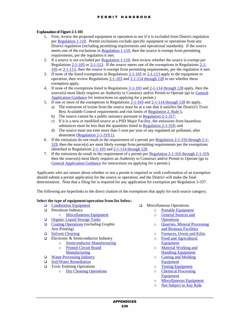
P E R M I T H A N D B O O K
APPENDICES
239
Explanation of Figure 2-1-101
1. First, review the proposed equipment or operation to see if it is excluded from District regulation
per Regulation 1-110. Permit exclusions exclude specific equipment or operations from any
District regulation (including permitting requirements and operational standards). If the source
meets one of the exclusions in Regulation 1-110, then the source is exempt from permitting
requirements, per the regulation it met.
2. If a source is not excluded per Regulation 1-110, then review whether the source is exempt per
Regulations 2-1-105 or 2-1-113. If the source meets one of the exemptions in Regulations 2-1-
105 or 2-1-113, then the source is exempt from permitting requirements, per the regulation it met.
3. If none of the listed exemptions in Regulations 2-1-105 or 2-1-113 apply to the equipment or
operation, then review Regulations 2-1-103 and 2-1-114 through 128 to see whether these
exemption apply.
4. If none of the exemptions listed in Regulations 2-1-103 and 2-1-114 through 128 apply, then the
source(s) most likely requires an Authority to Construct and/or Permit to Operate (go to General
Application Guidance for instructions on applying for a permit.)
5. If one or more of the exemptions in Regulations 2-1-103 and 2-1-114 through 128 do apply,
a) The emissions of toxins from the source must be at a rate that it satisfies the District's Toxic
Best Available Control requirements and risk limits of Regulation 2, Rule 5.
b) The source cannot be a public nuisance pursuant to Regulation 2-1-317;
c) If it is a new or modified source at a PSD Major Facility, the emissions from hazardous
substances must be less than the quantities listed in Regulation 2-1-318; and
d) The source must not emit more than 5 tons per year of any regulated air pollutant, after
abatement (Regulation 2-1-319.1).
6. If the emissions do not result in the requirement of a permit per Regulation 2-1-316 through 2-1-
319, then the source(s) are most likely exempt from permitting requirements per the exemptions
identified in Regulations 2-1-103 and 2-1-114 through 128.
7. If the emissions do result in the requirement of a permit per Regulation 2-1-316 through 2-1-319,
then the source(s) most likely requires an Authority to Construct and/or Permit to Operate (go to
General Application Guidance for instructions on applying for a permit.)
Applicants who are unsure about whether or not a permit is required or wish confirmation of an exemption
should submit a permit application for the source or operation; and the District will make the final
determination. Note that a filing fee is required for any application for exemption per Regulation 3-337.
The following are hyperlinks to the direct citation of the exemptions that apply for each source category.
Select the type of equipment/operation from list below:
Combustion Equipment
Petroleum Industry
o Miscellaneous Equipment
Organic Liquid Storage Tanks
Coating Operations (including Graphic
Arts Printing)
Solvent Cleaning
Electronic & Semiconductor Industry
o Semiconductor Manufacturing
o Printed Circuit Board
Manufacturing
Waste Processing Industry
Soil/Water Remediation
Toxic Emitting Operations
o Dry Cleaning Operations
Miscellaneous Operations
o Portable Equipment
o General Sources and
Operations
o Quarries, Mineral Processing
and Biomass Facilities
o Furnaces, Ovens and Kilns
o Food and Agricultural
Equipment
o Material Working and
Handling Equipment
o Casting and Molding
Equipment
o Testing Equipment
o Chemical Processing
Equipment
o Miscellaneous Equipment
o Not Subject to Any Rule

P E R M I T H A N D B O O K
APPENDICES
240
Excerpts from Regulation 1:
Regulation 1-110
1-110 Exclusions: District Regulations shall not apply to the following: 110.1 Engines used to propel motor vehicles, and defined by the Vehicle Code of
the State of California. 110.2 Deleted May 17, 2000. 110.3 Aircraft. 110.4 Fires from residential cooking. 110.5 Open outdoor fires, other than for the disposal of waste propellants,
explosives or pyrotechnics by manufacturing facilities; recreational fires and outdoor cooking fires, except as limited by Regulation 5.
110.6 Any emission point which is not an intended opening and from which no significant quantities of air contaminants are emitted.
110.7 Smoke generators intentionally operated to train observers in appraising the shade of emissions.
110.8 Air contaminants, where purposely emitted for the sole purpose of a specific beneficial use, and where essentially all of the air contaminants are confined to the area in which such beneficial use is obtained. The quantity and nature of the air contaminants, and the proportion of air contaminants used in relation to amounts of other materials involved in the beneficial use of air contaminants, shall conform to accepted practice in type of use employed.
110.9 Agricultural sources except as provided in: 9.1 Regulation 5: Open Burning; and 9.2 Regulation 2: Permits.
(Renumbered 3/17/82; Amended 12/19/90; 11/3/93; 5/17/00; 5/2/01; 7/19/06; 7/9/08)
Regulation 2-1-103 [see policy]
2-1-103 Exemption, Source not Subject to any District Rule: Any source that is not already exempt from the requirements of Section 2-1-301 and 302 as set forth in Sections 2-1-105 to 2-1-128, is exempt from Section 2-1-301 and 302 if the source meets all of the following criteria: 103.1 The source is not in a source category subject to any of the provisions of
Regulation 6(1), Regulation 8(2) excluding Rules 1 through 4, Regulations 9 through 12; and
103.2 The source is not subject to any of the provisions of Sections 2-1-316 through 319; and
103.3 Actual emissions of precursor organic compounds (POC), non-precursor organic compounds (NPOC), nitrogen oxides (NOx), sulfur dioxide (SO2), PM10 and carbon monoxide (CO) from the source are each less than 10 pounds per highest day. A source also satisfies this criterion if actual emissions of each pollutant are greater than 10 lb/highest day, but total emissions are less than 150 pounds per year, per pollutant.
Note 1: Typically, any source may be subject to Regulation 6, Particulate Matter and Visible Emissions. For the purposes of this section, Regulation 6 applicability shall be limited to the following types of sources that emit PM10: combustion source; material handling/processing; sand, gravel or rock processing; cement, concrete and asphaltic concrete production; tub grinder; or similar PM10-emitting source, as deemed by the APCO.
Note 2: If an exemption in a Regulation 8 Rule indicates that the source is subject to Regulation 8, Rules 1 through 4, then the source must comply with all applicable provisions of Regulation 8, Rules 1 through 4, to qualify for this exemption.
103.4 The source is not an ozone generator (a piece of equipment designed to generate ozone) emitting 1 lb/day or more of ozone.
(Adopted 6/7/95; Amended 5/17/00; 12/21/04)
Regulation 2-1-105

P E R M I T H A N D B O O K
APPENDICES
241
2-1-105 Exemption, Registered Statewide Portable Equipment: The following portable equipment is exempt from the requirements of Sections 2-1-301 and 302, provided that the equipment complies with all applicable requirements of the Statewide Portable Equipment Registration Program (California Code of Regulations Title 13, Division 3, Chapter 3, Article 5). 105.1 Confined abrasive blasting 105.2 Portland concrete batch plants 105.3 Spark ignition or diesel fired internal combustion engines used in conjunction
with the following types of operations: 3.1 Well drilling service or workover rigs; 3.2 Power generation, excluding cogeneration; 3.3 Pumps; 3.4 Compressors; 3.5 Pile drivers; 3.6 Welding; 3.7 Cranes; and 3.8 Wood chippers
105.4 Sand and Gravel screening, rock crushing, pavement crushing and recycling operations;
105.5 Unconfined abrasive blasting. (Adopted 6/7/95; Amended 10/7/98; 5/17/00)
Regulation 2-1-113
2-1-113 Exemption, Sources and Operations: 113.1 The following sources and operations are exempt from the requirements of
Sections 2-1-301 and 302, in accordance with the California Health and Safety Code: 1.1 Single and multiple family dwellings used solely for residential
purposes. 1.2 Agricultural sources with actual emissions of each regulated air
pollutant, excluding fugitive dust, less than 50 tons per year, except for large confined animal facilities subject to Regulation 2, Rule 10.
1.3 Any vehicle. Equipment temporarily or permanently attached to a vehicle is not considered to be a part of that vehicle unless the combination is a vehicle as defined in the Vehicle Code. Specialty vehicles may include temporarily or permanently attached equipment including, but are not limited to, the following: oil well production service unit; special construction equipment; and special mobile equipment.
1.4 Tank vehicles with vapor recovery systems subject to state certification, in accordance with the Health and Safety Code.
113.2 The following sources and operations are exempt from the requirements of Sections 2-1-301 and 302: 2.1 Road construction, widening and rerouting. 2.2 Restaurants, cafeterias and other retail establishments for the purpose
of preparing food for human consumption. 2.3 Structural changes which do not change the quality, nature or quantity
of air contaminant emissions. 2.4 Any abatement device which is used solely to abate equipment that
does not require an Authority to Construct or Permit to Operate. 2.5 Architectural and industrial maintenance coating operations that are
exclusively subject to Regulation 8, Rules 3 or 48, because coatings are applied to stationary structures, their appurtenances, to mobile homes, to pavements, or to curbs. This does not apply to coatings applied by the manufacturer prior to installation, nor to the coating of components removed from such structures and equipment.
P E R M I T H A N D B O O K
APPENDICES
242
2.6 Portable abatement equipment exclusively used to comply with the tank degassing or vacuum truck control requirements of Regulation 8, Rules 5, 40 or 53.
2.7 Equipment that transports, holds or stores California Public Utilities Commission regulated natural gas, excluding drivers.
2.8 Deleted May 17, 2000 2.9 Deleted May 17, 2000 2.10 Deleted May 17, 2000 2.11 Teaching laboratories used exclusively for classroom experimentation
and/or demonstration. 2.12 Laboratories located in a building where the total laboratory floor space
within the building is less than 25,000 square feet, or the total number of fume hoods within the building is less than 50, provided that Responsible Laboratory Management Practices, as defined in Section 2-1-224, are used. Buildings connected by passageways and/or corridors shall be considered as separate buildings, provided that structural integrity could be maintained in the absence of the passageways and/or corridors and the buildings have their own separate and independently operating HVAC and fire suppression systems. For the purposes of this subsection, teaching laboratories that are exempt per Section 2-1-113.2.11 are not included in the floor space or fume hood totals. In addition, laboratory units for which the owner or operator of the source can demonstrate that toxic air contaminant emissions would not occur, except under accidental or upset conditions, are not included in the floor space or fume hood totals.
2.13 Maintenance operations on natural gas pipelines and associated equipment, provided that emissions from such operations consist solely of residual natural gas that is vented after the equipment is isolated or shut down.
2.14 Space heating units that are not subject to Regulation 9, Rule 7, where emissions result solely from the combustion of natural gas or liquefied petroleum gas (e.g. propane, butane, isobutane, propylene, butylenes, and their mixtures) of less than 20 million BTU per hour heat input. Incinerators operated in conjunction with such sources are not exempt.
2.15 Asbestos and asbestos containing material renovation or removal conducted in compliance with Regulation 11, Rule 2 and Regulation 3.
2.16 Closed landfills that have less than 1,000,000 tons of decomposable solid waste in place and that do not have an operating landfill gas collection system.
2.17 Closed landfills that have not accepted waste for at least 30 years and that never had a landfill gas collection system.
2.18 Construction of a building or structure that is not itself a source requiring a permit.
2.19 Vacuum trucks subject to Regulation 8, Rule 53 and processing regulated material as defined in that rule.
(Adopted 10/19/83; Amended 7/17/91; 6/7/95; 5/17/00; 11/15/00; 5/2/01; 7/19/06; 4/18/12)
Regulation 2-1-114 through 128
2-1-114 Exemption, Combustion Equipment: The following equipment is exempt from the requirements of Sections 2-1-301 and 302, only if the source does not emit pollutants other than combustion products, and those combustion products are not caused by the combustion of a pollutant generated from another source, and the source does not require permitting pursuant to Section 2-1-319. 114.1 Boilers, Heaters, Steam Generators, Duct Burners, and Similar Combustion
Equipment: 1.1 Any of the above equipment with less than 1 million BTU per hour
rated heat input.

P E R M I T H A N D B O O K
APPENDICES
243
1.2 Any of the above equipment with less than 10 million BTU per hour rated heat input if fired exclusively with natural gas (including compressed natural gas), liquefied petroleum gas (e.g. propane, butane, isobutane, propylene, butylenes, and their mixtures), or any combination thereof.
114.2 Internal Combustion Engines and Gas Turbines: 2.1 Internal combustion (IC) engines and gas turbines with a maximum
output rating less than or equal to 50 hp. 2.2 Internal combustion (IC) engines and gas turbines used solely for
instructional purposes at research, teaching, or educational facilities. 2.3 Portable internal combustion engines which are at a location for less
than 72 consecutive hours. 2.4 Any engine mounted on, within, or incorporated into any vehicle, train,
ship, boat, or barge used to provide propulsion for the vehicle, train, ship, boat, or barge. Facilities which include cargo loading or unloading from cargo carriers other than motor vehicles shall include the cargo carriers as part of the source which receives or loads the cargo.
2.5 Any engine mounted on, within, or incorporated into any vehicle, train, ship, boat, or barge used to provide propulsion for the vehicle, train, ship, boat, or barge and which is also used to supply mechanical or electrical power to ancillary equipment (e.g., crane, drill, winch, etc.) which is affixed to or is a part of the vehicle, train, ship, boat, or barge. Facilities which include cargo loading or unloading from cargo carriers other than motor vehicles shall include the cargo carriers as part of the source which receives or loads the cargo.
(Adopted 10/19/83; Amended 7/17/91; 6/7/95; 5/17/00; 8/1/01)
2-1-115 Exemption, Particulate Sources at Quarries, Mineral Processing and Biomass Facilities: The following potential PM10 sources are exempt from the requirements of sections 2-1-301 and 302, provided that the source does not require permitting pursuant to Section 2-1-319. 115.1 Sources located at quarrying; mineral or ore handling or processing; concrete
production; asphaltic concrete production; marine bulk transfer stations; concrete or asphaltic concrete recycling; vehicle shredding; glass manufacturing; handling or processing of cement, coke, lime, flyash, fertilizer, or catalyst; or other similar facility which meets one of the following: 1.1 Mixer and other ancillary sources at concrete or aggregate product
production facilities with a maximum rated production capacity less than 15 cubic yards (yd3) per hour;
1.2 Other source at a facility with a maximum throughput less than 5000 tons per year;
1.3 Operating, loading and unloading a crusher or grinder which processes exclusively material with a moisture content greater than or equal to 20 percent by weight;
1.4 Operating, loading and unloading the following sources which process exclusively material with a moisture content greater than or equal to 5 percent by weight: 1.4.1 Screen or other size classification; 1.4.2 Conveyor, screw, auger, stacker or bucket elevator; 1.4.3 Grizzly, or other material loading or unloading; 1.4.4 Storage silos; 1.4.5 Storage or weigh hopper/bin system.
1.5 Haul or access roads; 1.6 Drilling or blasting.
115.2 Sources located at biomass recycling, composting, landfill, POTW, or related facilities specializing in the operation of, but not limited to, the following: 2.1 Tub grinder powered by a motor with a maximum output rating less
than 10 horsepower;

P E R M I T H A N D B O O K
APPENDICES
244
2.2 Hogger, shredder or similar source powered by a motor with a maximum output rating less than 25 horsepower;
2.3 Other biomass processing/handling sources at a facilities with a total throughput less than 500 tons per year.
(Amended 6/7/95; 5/17/00)
2-1-116 Exemption, Furnaces, Ovens and Kilns: The following equipment is exempt from the requirements of Sections 2-1-301 and 302, provided that the source does not require permitting pursuant to Section 2-1-319. 116.1 Porcelain enameling furnaces, porcelain enameling drying ovens, vitreous
enameling furnaces or vitreous enameling drying ovens. 116.2 Crucible furnaces, pot furnaces, induction furnaces, cupolas, electric arc
furnaces, reverbatories, or blast furnaces with a capacity of 1000 lbs or less each.
116.3 Crucible furnaces, pot furnaces, or induction furnaces for sweating or distilling that process 100 tons per year of all metals or less.
116.4 Drying or heat-treating ovens with less than 10 million BTU per hour capacity provided that a) the oven does not emit pollutants other than combustion products and b) the oven is fired exclusively with natural gas (including compressed natural gas), liquefied petroleum gas (e.g. propane, butane, isobutane, propylene, butylenes, and their mixtures), or any combination thereof.
116.5 Ovens used exclusively for the curing of plastics which are concurrently being vacuum held to a mold, or for the softening and annealing of plastics.
116.6 Ovens used exclusively for the curing of vinyl plastisols by the closed mold curing process.
116.7 Ovens used exclusively for curing potting materials or castings made with epoxy resins.
116.8 Kilns used for firing ceramic ware, heated exclusively by natural gas, liquefied petroleum gas, electricity or any combination thereof.
116.9 Parts cleaning, bake-off, and similar ovens that meet both of the following: 9.1 Oven is equipped with a secondary combustion chamber or abated by
a fume incinerator; and 9.2 Internal oven volume is 1 cubic yard or less.
116.10 Electric ovens used exclusively for curing or heat-treating where no significant off-gassing or evaporation of any air contaminants occurs.
(Adopted 10/19/83; Amended 7/17/91; 6/7/95; 5/17/00)
2-1-117 Exemption, Food and Agricultural Equipment: The following equipment is exempt from the requirements of Sections 2-1-301 and 302, provided that the source does not require permitting pursuant to Section 2-1-319. 117.1 Smokehouses or barbecue units in which the maximum horizontal inside
cross sectional area does not exceed 20 square feet. 117.2 Equipment at facilities other than restaurants, cafeterias or other retail
operations, which is used to dry, cook, fry, bake, or grill less than 1000 tons per year of food products.
117.3 Any oven with a total production of yeast leavened bakery products of less than 10,000 pounds per operating day, averaged over any period of seven consecutive days, and which is heated either electrically or exclusively by natural gas firing with a maximum capacity of less than 10 million BTU per hour.
117.4 Equipment used exclusively to grind, blend, package, or store tea, cocoa, spices, or coffee.
117.5 Equipment used to dry, mill, grind, blend, or package less than 1000 tons per year of dry food products such as seeds, grains, corn, meal, flour, sugar, and starch.
117.6 Equipment used to convey, transfer, clean, or separate less than 1000 tons per year of dry food products or waste from food production operations.

P E R M I T H A N D B O O K
APPENDICES
245
117.7 Storage equipment or facilities containing dry food products; which are not vented to the outside atmosphere, or which handle less than 1000 tons per year.
117. 8 Coffee, cocoa and nut roasters with a roasting capacity of less than 15 pounds of beans or nuts per hour; and any stoners or coolers operated in conjunction with these roasters.
117.9 Containers, reservoirs, tanks, or loading equipment used exclusively for the storage or loading of beer, wine or other alcoholic beverages.
117.10 Fermentation tanks for beer or wine. Fermentation tanks used for the commercial production of yeast for sale are not exempt.
117.11 Brewing operations at facilities producing less than 3 million gallons per year of beer.
117.12 Fruit sulfuring operations at facilities producing less than 10 tons per year of sulfured fruits and vegetables.
(Adopted 10/19/83; Amended 4/16/86; 7/1791; 6/7/95; 5/17/00)
2-1-118 Exemption, Surface Preparation and Cleaning Equipment: The following equipment is exempt from the requirements of Sections 2-1-301 and 302, provided that the source does not require permitting pursuant to Section 2-1-319. 118.1 Permanent abrasive blasting source, as defined by Regulation 12, Rule 4,
that has a confined volume less than 100 cubic feet (ft3) and is abated by a particulate filter.
118.2 Blast cleaning equipment using a suspension of abrasive in water. 118.3 Portable abrasive blasting equipment used on a temporary basis within the
District. 118.4 Equipment, including solvent cold cleaners using an unheated solvent
mixture for surface preparation, cleaning, wipe cleaning, fluxing or stripping by use of solutions with a VOC content less than or equal to 50 grams per liter (0.42 lb/gal).
118.5 Equipment using a heated solvent mixture for steam cleaning, surface preparation, fluxing, stripping, wipe cleaning, washing or drying products, provided that a) only solutions containing less than 2.5 percent VOC (wt) are used; and b) any combustion sources used in the process are exempt under Section 2-1-114.
118.6 Equipment or operations which use unheated solvent and which contain less than 1 gallon of solvent or have a liquid surface area of less than 1 ft2. This exemption does not apply to solvent stations at semiconductor manufacturing operation fabrication areas or aerospace stripping operations.
118.7 Deleted December 21, 2004 118.8 Batch solvent recycling equipment where all of the following apply:
8.1 Recovered solvent is used primarily on site (more than 50% by volume); and
8.2 Maximum heat input (HHV) is less than 1 million BTU per hour; and 8.3 Batch capacity is less than 150 gallons.
118.9 Wipe cleaning at a facility with a net solvent usage less than 20 gallons per year, or which emits to the atmosphere less than 150 lb/year of VOC from all wipe cleaning operations. At a facility with total wipe cleaning emissions greater than 150 lb/yr, wipe cleaning operations may be grouped per Section 2-1-401.4.
118.10 Any solvent cleaning or surface preparation source which employs only non-refillable hand held aerosol cans.
118.11 Spray gun cleaning performed in compliance with Regulation 8, provided the cleaning is associated with a source, such as a spray booth, subject to the requirements of Section 2-1-301 and 302.
(Adopted 10/19/83; Amended 4/16/86; 8/2/89; 7/17/91; 6/7/95; 5/17/00; 12/21/04)
2-1-119 Exemption, Surface Coating and Printing Equipment: The following equipment and operations are exempt from the requirements of Sections 2-1-301 and 302, provided that the source does not require permitting pursuant to Section 2-1-319.

P E R M I T H A N D B O O K
APPENDICES
246
119.1 Any powder coating operation, or radiation cured coating operation where ultraviolet or electron beam energy is used to initiate a reaction to form a polymer network.
119.2 Any coating, adhesive, dipping, laminating, screening, masking, electrodeposition, resist application, or similar source or operation at any facility that is not operated or conducted as part of a graphic arts operation, which: 2.1 Consumes a total of less than 30 gallons of coating, adhesive,
laminate or resist per year on a facility wide basis, or emits less than 150 pounds per year of uncontrolled VOC on a facility wide basis, resulting from the application of these materials; or
2.2 Uses exclusively materials that contain less than one percent VOC (wt).
At a facility with emissions from these sources or operations of greater than 150 lb/yr, these sources or operations may be grouped per Section 2-1-401.3.
119.3 Any coating source which employs only non-refillable hand held aerosol cans.
119.4 An oven associated with an exempt coating source, provided that the oven is electrically heated, or the oven is fired exclusively with natural gas, liquefied petroleum gas (e.g. propane, butane, isobutane, propylene, butylenes, and their mixtures) and the maximum firing rate is less than 10 million BTU per hour.
119.5 Any graphic arts operation that emits less than 400 pounds of VOC emissions per month on a facility-wide basis.
(Adopted 10/19/83; Amended 4/16/86; 7/17/91; 6/7/95; 5/17/00; 12/21/04; 11/19/08)
2-1-120 Exemption, Dry Cleaning Equipment: Any dry cleaning facility which uses (gross consumption) less than 200 gallons of petroleum solvent or any other non-halogenated solvent in any single year is exempt from the requirements of Sections 2-1-301 and 302, provided that the source does not require permitting pursuant to Section 2-1-319; the facility is in compliance with the registration requirement in Regulation 8, Rule 17, Section 404; and the equipment does not use solvent that contains perchloroethylene or more than 1% by weight of any other halogenated compound.
(Adopted 10/19/83; Amended 7/17/91; 6/7/95; 5/17/00; 3/4/09)
2-1-121 Exemption, Material Working and Handling Equipment: The following equipment is exempt from the requirements of Sections 2-1-301 and 302, provided that the source does not require permitting pursuant to Section 2-1-319. 121.1 Equipment used for buffing, carving, cutting, drilling, grinding, machining,
planing, routing, sanding, sawing, shredding, stamping or turning of wood, ceramic artwork, ceramic precision parts, leather, metals, plastics, rubber, fiberboard, masonry, glass, silicon, semiconductor wafers, carbon or graphite, provided that organic emissions from the use of coolant, lubricant, or cutting oil are 5 ton/yr or less.
121.2 Equipment used for pressing or storing sawdust, wood chips or wood shavings.
121.3 Equipment used exclusively to mill or grind coatings and molding compounds in a paste form provided the solution contains less than one percent VOC (wt).
121.4 Tumblers used for the cleaning or deburring of metal products without abrasive blasting.
121.5 Batch mixers with a rated working capacity of 55 gallons or less. 121.6 Mixing equipment provided no material in powder form is added and mixture
contains less than one percent VOC (wt). 121.7 Equipment used exclusively for the mixing and blending of materials at
ambient temperature to make water based adhesives. 121.8 Equipment used exclusively for the mixing and packaging of lubricants or
greases.

P E R M I T H A N D B O O K
APPENDICES
247
121.9 Presses used exclusively for extruding metals, minerals, plastics or wood. 121.10 Presses used for the curing of rubber products and plastic products. The use
of mold release products or lubricants is not exempt unless the VOC content of these materials is less than or equal to 1 percent, by weight, or unless the total facility-wide uncontrolled VOC emissions from the use of these materials are less than 150 lb/yr.
121.11 Platen presses used for laminating. 121.12 Roll mills or calendars for rubber or plastics. 121.13 Equipment used exclusively for forging, pressing, rolling, stamping or
drawing metals or for heating metals immediately prior to forging, pressing, rolling, stamping or drawing, provided that: (1) maximum fuel use rate is less than 10 million BTU/hr; (2) no lubricant with an initial boiling point less than 400oF is used; and (3) organic emissions are 5 ton/yr or less.
121.14 Atmosphere generators used in connection with metal heat treating processes.
121.15 Equipment used exclusively for the sintering of glass or metals. 121.16 Equipment used exclusively for the melting or applying of wax containing less
than one percent VOC (wt). 121.17 Equipment used exclusively for conveying and storing plastic pellets. 121.18 Solid waste transfer stations that receive or load out a total of all material
less than 50 tons/day. 121.19 Inactive solid waste disposal sites which do not have an operating landfill gas
collection system. (Adopted 10/19/83; Amended 7/17/91; 6/7/95; 5/17/00)
2-1-122 Exemption, Casting and Molding Equipment: The following equipment is exempt from the requirements of Sections 2-1-301 and 302, provided that the source does not require permitting pursuant to Section 2-1-319. 122.1 Molds used for the casting of metals. 122.2 Foundry sand mold forming equipment to which no heat is applied, except
processes utilizing organic binders yielding in excess of 0.25% free phenol by weight of sand.
122.3 Shell core and shell-mold manufacturing machines. 122.4 Equipment used for extrusion, compression molding and injection molding of
plastics. The use of mold release products or lubricants is not exempt unless the VOC content of these materials is less than or equal to 1 percent, by weight, or unless the total facility-wide uncontrolled VOC emissions from the use of these materials are less than 150 lb/yr.
122.5 Die casting machines. (Adopted 10/19/83; Amended 7/17/91; 6/7/95; 5/17/00)
2-1-123 Exemption, Liquid Storage and Loading Equipment: The following equipment is exempt from the requirements of Sections 2-1-301 and 302, provided that the source does not require permitting pursuant to Section 2-1-319. 123.1 Storage tanks and storage vessels having a capacity of less than 260
gallons. 123.2 Tanks, vessels and pumping equipment used exclusively for the storage or
dispensing of any aqueous solution which contains less than 1 percent (wt) organic compounds. Tanks and vessels storing the following materials are not exempt. 2.1 Sulfuric acid with an acid strength of more than 99.0% by weight. 2.2 Phosphoric acid with an acid strength of more than 99.0% by weight. 2.3 Nitric acid with an acid strength of more than 70.0% by weight. 2.4 Hydrochloric acid with an acid strength of more than 30.0% by weight. 2.5 Hydrofluoric acid with an acid strength of more than 30.0% by weight. 2.6 More than one liquid phase, where the top phase contains more than
one percent VOC (wt). 123.3 Containers, reservoirs, tanks or loading equipment used exclusively for:
3.1 Storage or loading of liquefied gases.

P E R M I T H A N D B O O K
APPENDICES
248
3.2 Storage or loading of organic liquids or mixtures containing organic liquids; where the initial boiling point of the organics is greater than 302oF and exceeds the actual storage temperature by at least 180oF. This exemption does not apply to the storage or loading of asphalt or asphalt emulsion with a sulfur content equal to or greater than 0.5 wt%.
3.3 The storage or loading of petroleum oils with an ASTM D-93 (PMCC) flash point of 130oF or higher, when stored or loaded at a temperature at least 36oF below the flash point.
3.4 The storage or loading of lubricating oils. 3.5 The storage of fuel oils with a gravity of 40 API or lower and having a
capacity of 10,000 gallons or less. 3.6 The storage or loading of liquid soaps, liquid detergents, tallow, or
vegetable oils, waxes or wax emulsions. 3.7 The storage of asphalt or asphalt emulsion with a sulfur content of less
than 0.5 wt%. This does not include the storage of asphalt cutback with hydrocarbons having an initial boiling point of less than 302oF.
3.8 The storage of wine, beer or other alcoholic beverages. 3.9 The storage of organic salts or solids in an aqueous solution or
suspension, provided that no liquid hydrocarbon layer forms on top of the aqueous phase.
3.10 The storage or loading of fuel oils with a gravity of 25 API or lower. 3.11 The storage and/or transfer of an asphalt-water emulsion heated to
150oF or less. 123.4 Tank seal replacement. For any tank subject to Regulation 8, Rule 5, any
new seal must comply with the applicable provisions of Regulation 8, Rule 5, and the District must receive written notification of the tank source number and seal type at least three days prior to the installation.
(Adopted 10/19/83; Amended 7/11/84; 7/17/91; 6/7/95; 5/17/00)
2-1-124 Exemption, Semiconductor Manufacturing: Semiconductor fabrication area(s) at a facility which complies with all of the following are exempt from the requirements of Sections 2-1-301 and 302, provided that the source does not require permitting pursuant to Section 2-1-319. 124.1 Net solvent usage is less than 20 gallons of VOC per year on a facility wide
basis; or uncontrolled VOC emissions to the atmosphere resulting from the usage of solvent are less than 150 pounds per year of VOC on a facility wide basis, and
124.2 Maskant and/or coating usage is less than 30 gallons per year, on a facility wide basis; or uncontrolled VOC emissions from the application of maskant and coatings are less than 150 pounds per year on a facility wide basis.
(Adopted 10/19/83; Amended 1/9/85; 4/16/86; 7/17/91; 6/7/95; 10/20/99; 5/17/00)
2-1-125 Exemption, Printed Circuit Board Manufacturing Equipment: The following equipment is exempt from the requirements of Sections 2-1-301 and 302, provided that the source does not require permitting pursuant to Section 2-1-319. 125.1 Equipment used exclusively for:
1.1 Plating of printed circuit boards. 1.2 Buffing, polishing, carving, cutting, drilling, machining, routing, sanding,
sawing, surface grinding or turning of printed circuit boards. 1.3 Soldering. This section does not exempt fluxing and finger cleaning
(see Section 2-1-118.4). (Adopted 10/19/83; Amended 7/17/91; 6/7/95; 5/17/00)
2-1-126 Exemption, Testing Equipment: The following equipment is exempt from the requirements of Sections 2-1-301 and 302, provided that the source does not require permitting pursuant to Section 2-1-319. 126.1 Equipment used for hydraulic or hydrostatic testing. 126.2 Bench scale laboratory equipment or processes used exclusively for
chemical or physical analyses or experimentation, quality assurance and quality control testing, research and development, or similar bench scale equipment, excluding pilot plants.

P E R M I T H A N D B O O K
APPENDICES
249
126.3 Equipment used for inspection of metal products. (Adopted 10/19/83; Amended 7/17/91; 6/7/95; 5/17/00)
2-1-127 Exemption, Chemical Processing Equipment: The following equipment is exempt from the requirements of Sections 2-1-301 and 302, provided that the source does not require permitting pursuant to Section 2-1-319. 127.1 Equipment used exclusively for the dyeing or stripping (bleaching) of textiles
provided that only solutions containing less than one percent VOC (wt) are used.
127.2 Photographic process equipment by which an image is reproduced upon material sensitized to radiant energy.
127.3 Containers, reservoirs, or tanks used exclusively for electrolytic plating with, or electrolytic polishing of, or electrolytic stripping of the following metals: aluminum, brass, bronze, cadmium, copper, iron, nickel, tin, zinc and precious metals.
127.4 Containers, reservoirs, or tanks used exclusively for etching (not chemical milling), except where ammonia or ammonium-based etchants are used.
(Adopted 10/19/83; Amended 7/17/91; 6/7/95; 5/17/00)
2-1-128 Exemption, Miscellaneous Equipment: The following equipment is exempt from the requirements of Sections 2-1-301 and 302, provided that the source does not require permitting pursuant to Section 2-1-319. 128.1 Comfort air conditioning or comfort ventilating systems which are not
designed to remove air contaminants generated by or released from specific units of equipment.
128.2 Refrigeration units except those used as, or in conjunction with, air pollution control equipment.
128.3 Vacuum producing devices in laboratory operations which are used exclusively in connection with other equipment which is exempted by this Rule, and vacuum producing devices which do not remove or convey air contaminants from another source.
128.4 Water cooling towers and water cooling ponds not used for evaporative cooling of process water, or not used for evaporative cooling of water from barometric jets or from barometric condensers.
128.5 Natural draft hoods, natural draft stacks or natural draft ventilators. 128.6 Vacuum cleaning system used exclusively for industrial commercial or
residential housekeeping purposes. 128.7 Equipment used to liquefy or separate oxygen, nitrogen or the rare gases
from the air. 128.8 Equipment used exclusively to compress or hold dry natural gas, excluding
drivers. 128.9 Equipment used exclusively for bonding lining to brake shoes. 128.10 Equipment used exclusively for the manufacture of water emulsions of
waxes, greases or oils. 128.11 Brazing, soldering or welding equipment. 128.12 Pharmaceutical manufacturing equipment with annual VOC emissions less
than 150 pounds per source. Material working and handling equipment such as mills, grinders, blenders, granulators, tablet presses, capsule fillers, packagers, and conveyors are only exempt if the source also processes less than 100 tons per year of pharmaceutical products.
128.13 Equipment used exclusively to blend or package cosmetics. 128.14 Any wastewater (oil-water) separator, as defined in Regulation 8, Rule 8,
which processes less than 200 gallons per day of waste water containing organic liquids.
128.15 Exploratory drilling activities for methane recovery at waste disposal sites, for natural gas or for oil. Production wells for the above operations are not exempt.
128.16 Passive aeration of soil, only if: 16.1 The duration of the passive aeration operation will not exceed three
months, and

P E R M I T H A N D B O O K
APPENDICES
250
16.2 The soil is not being used as a cover material at a landfill. 128.17 Ozone generators which produce less than 1 pound per day of ozone. 128.18 Any source or operation which exclusively uses consumer products regulated
by the California Air Resources Board (California Code of Regulations Title 17, Article 2, Sections 94507-94517).
128.19 Any source or operation deemed by the APCO to be equivalent to a source or operation which is expressly exempted by Sections 2-1-113 through 128.
128.20 Wastewater pumping stations where no treatment is performed, excluding any drivers.
128.21 Modification, replacement, or addition of fugitive components (e.g. valves, flanges, pumps, compressors, relief valves, process drains) at existing permitted process units at petroleum refineries, chemical plants, bulk terminals or bulk plants, provided that the cumulative emissions from all additional components installed at a given process unit during any consecutive twelve month period do not exceed 10 lb/day, and that the components meet applicable requirements of Regulation 8 rules.
128.22 Fuel cells that use phosphoric acid, molten carbonate, proton exchange membrane, solid oxide or equivalent technologies.
128.23 Structure demolition that does not involve asbestos or asbestos containing materials.
(Adopted 10/19/83; Amended 7/16/86; 7/17/91; 6/7/95; 5/17/00; 11/15/00; 12/21/04)
Regulation 2-1-301
2-1-301 Authority to Construct: Any person who, after July, 1972, puts in place, builds, erects, installs, modifies, modernizes, alters or replaces any article, machine, equipment or other contrivance, the use of which may cause, reduce or control the emission of air contaminants, shall first secure written authorization from the APCO in the form of an authority to construct. Routine repairs, maintenance, or cyclic maintenance that includes replacement of components with identical components is not considered to be an alteration, modification or replacement for the purpose of this Section unless the APCO determines the changes to be non-routine. The use or operation of the source shall initiate the start-up period in accordance with Section 2-1-411.
(Amended 3/17/82; 10/19/83; 7/17/91; 5/17/00)
Regulation 2-1-302
2-1-302 Permit to Operate: Before any person, as described in Section 2-1-401, uses or operates any article, machine, equipment or other contrivance, the use of which may cause, reduce or control the emission of air contaminants, such person shall first secure written authorization from the APCO in the form of a permit to operate. 302.1 Permit to Operate, MFR: Any facility subject to the requirements of
Regulation 2-6, Major Facility Review, shall comply with the permitting requirements included herein in addition to securing a permit to operate under this rule.
302.2 Permit to Operate, Accelerated Permitting Program: Installation and operation of a new or modified source or abatement device which qualifies for the Accelerated Permitting Program under Section 2-1-106 may commence immediately following the submittal of a complete permit application. A temporary Permit to Operate will be issued as soon as the APCO determines that the application is complete. Action shall be taken on the application within 35 working days of receipt of a complete application, in accordance with Section 2-1-408, provided that the applicable offset provisions of Regulation 2, Rule 2, Sections 302 and 303 are satisfied. During periods that the source is operating without a Permit to Operate, the operator shall keep records sufficient to demonstrate that emissions do not exceed qualifying levels for the Accelerated Permitting Program.
302.3 Permit to Operate, Temporary Operation: A temporary permit may be obtained to allow an operator to test equipment, processes, or new

P E R M I T H A N D B O O K
APPENDICES
251
formulations. A temporary permit may also be obtained for a temporary source which replaces critical equipment during scheduled maintenance. The APCO may issue a non-renewable temporary Permit to Operate a temporary operation at any source, subject to the following: 3.1 The proposed operation will comply with all requirements of Regulation
1 and Regulations 5 through 12. 3.2 The permit shall expire 3 months after issuance. 3.3 The operator shall provide offsets, at a ratio of 1.15 to 1, for all
increased emissions of NOx, POC, and PM10 resulting from the use of the temporary permit.
3.4 The operator shall certify that the temporary operation is for one of the following purposes: 4.1 Equipment testing 4.2 Process testing, including new formulations 4.3 Temporary replacement of an existing permitted source with an
identical or functionally equivalent source (Amended 11/3/93; 6/7/95; 10/7/98; 11/15/00)
Regulation 2-1-316 through 2-1-319
2-1-316 New or Modified Sources of Toxic Air Contaminants or Hazardous Air Pollutants: Notwithstanding any exemption contained in Section 2-1-103 or Section 114 through 128, any new or modified source meeting any of the following criteria shall be subject to the requirements of Regulation 2, Rule 1, Section 301 and/or 302. 316.1 If a new or modified source emits one or more toxic air contaminants in
quantities that exceed the trigger levels listed in Table 2-5-1 of Regulation 2-5 and the source did not have a valid exemption from Regulation 2-1-302 when the source was constructed or modified, then the source shall be subject to the requirements of Sections 2-1-301 and 302, unless the owner or operator of the source can demonstrate to the satisfaction of the APCO that the source: 1.1 Will comply with the TBACT requirement of Regulation 2-5-301 (if
applicable); and 1.2 Will comply with the project risk limits of Regulation 2-5-302 (if
applicable). 316.2 If a new or modified source, or group of related sources in a proposed
construction or modification will emit 2.5 or more tons per year of any single hazardous air pollutant or 6.25 or more tons per year of any combination of hazardous air pollutants, then the source or group of sources shall be subject to the requirements of Sections 2-1-301 and 302.
(Adopted 4/16/86; Amended 7/17/91;Renumbered and Amended 6/7/95; Amended 5/17/00; 6/15/05)
2-1-317 Public Nuisance Sources: Notwithstanding any exemption contained in Section 2-1-103 or Section 114 through 128, any new or modified source meeting any of the following criteria shall be subject to the requirements of Regulation 2, Rule 1, Section 301 and/or 302. If any exempt source receives two or more public nuisance violations, under Regulation 1, Section 301 or Section 41700 of the California Health & Safety Code, within any consecutive 180-day period, then the source shall be subject to the requirements of Section 2-1-301 and 302. Such a source will be treated as loss of exemption source under Section 2-1-414, and will be subject to the annual permit to operate fee specified in Regulation 3. This section does not apply to a source that is exempt per section 2-1-113.
(Adopted 6/7/95; Amended 5/17/00)
2-1-318 Hazardous Substances: Notwithstanding any exemption contained in Section 2-1-103 or Section 114 through 128, any new or modified source meeting any of the following criteria shall be subject to the requirements of Regulation 2, Rule 1, Section 301 and/or 302. If a new or modified source at a PSD Major Facility, as defined in Regulation 2, Rule 2, Section 220.3, emits the following air contaminants in excess of the quantities listed below, then it is subject to the requirements of Sections 2-1-301 and 302.
P E R M I T H A N D B O O K
APPENDICES
252
318.1 0.6 ton per year of lead, 318.2 0.007 ton per year of asbestos (excepting demolition, renovation, and waste
disposal), 318.3 0.0004 ton per year of beryllium, 318.4 0.1 ton per year of mercury, 318.5 1 ton per year of vinyl chloride, 318.6 3 tons per year of fluorides, 318.7 7 tons per year of sulfuric acid mist, and 318.8 10 tons per year of reduced sulfur compounds (including hydrogen sulfide).
(Adopted 10/19/83; Renumbered and Amended 6/7/95; Amended 5/17/00)
2-1-319 Source Expressly Subject to Permitting Requirements: Notwithstanding any exemption contained in Section 2-1-103 or Section 114 through 128, any source meeting any of the following criteria shall be subject to the requirements of Section 2-1-302: 319.1 The emission rate of any regulated air pollutant from the source is greater
than 5 tons per year, after abatement. 319.2 The source is subject to the requirements of Section 2-1-316, 317, or 318.
(Adopted May 17, 2000)
Regulation 2-5-301
2-5-301 Best Available Control Technology for Toxics (TBACT) Requirement: The applicant shall apply TBACT to any new or modified source of TACs where the source risk is a cancer risk greater than 1.0 in one million (10-6), and/or a chronic hazard index greater than 0.20.
Regulation 2-5-302
2-5-302 Project Risk Requirement: The APCO shall deny an Authority to Construct or Permit to Operate for any new or modified source of TACs if the project risk exceeds any of the following project risk limits: 302.1 A cancer risk of 10.0 in one million (10-5). 302.2 A chronic hazard index of 1.0. 302.3 An acute hazard index of 1.0.

P E R M I T H A N D B O O K
APPENDICES
253
TABLE 2-5-1
Toxic Air Contaminant Trigger Levels
Inhalation Oral Acute Acute Chronic Chronic Cancer Cancer (1-hr. max.) Chronic CAS Inhalation Inhalation Oral Potency Potency Trigger Trigger Chemical Number i REL REL REL Factor Factor Level ii Level 2 (g/m3) (g/m3) (mg/kg-day) (mg/kg-day)-1 (mg/kg-day)-1 (lb/hour) (lb/year)
Acetaldehyde 75-07-0 9.0E+00 1.0E-02 6.4E+01
Acetamide 60-35-5 7.0E-02 9.1E+00
Acrolein 107-02-8 1.9E-01 6.0E-02 4.2E-04 2.3E+00
Acrylamide 79-06-1 7.0E-01 4.5E+00 1.4E-01
Acrylic acid 79-10-7 6.0E+03 1.0E+00 1.3E+01 3.9E+01
Acrylonitrile 107-13-1 5.0E+00 1.0E+00 6.4E-01
Allyl chloride 107-05-1 1.0E+00 2.1E-02 3.0E+01
Aminoanthraquinone, 2- 117-79-3 3.3E-02 1.9E+01
Ammonia 7664-41-7 3.2E+03 2.0E+02 7.1E+00 7.7E+03
Aniline 62-53-3 1.0E+00 5.7E-03 3.9E+01
Antimony compounds 7440-36-0 2.0E-01 7.7E+00
antimony trioxide 1309-64-4 2.0E-01 7.7E+00
Arsenic and compounds (inorganic) iii, iv 7440-38-2 1.9E-01 3.0E-02 3.0E-04 1.2E+01 1.5E+00 4.2E-04 1.2E-02
Arsine 7784-42-1 1.6E+02 5.0E-02 3.5E-01 1.9E+00
Asbestos v 1332-21-4 2.2E+02 2.9E-03
Benzene 3 71-43-2 1.3E+03 6.0E+01 1.0E-01 2.9E+00 6.4E+00
Benzidine (and its salts) 92-87-5 1.0E+01 5.0E+02 1.3E-03
benzidine based dyes 1.0E+01 5.0E+02 1.3E-03
direct black 38 1937-37-7 1.0E+01 5.0E+02 1.3E-03
direct blue 6 2602-46-2 1.0E+01 5.0E+02 1.3E-03
direct brown 95 (technical grade) 16071-86-6 1.0E+01 5.0E+02 1.3E-03
Benzyl chloride 100-44-7 2.4E+02 1.2E+01 1.7E-01 5.3E-01 3.8E+00
Beryllium and compounds 4 7440-41-7 7.0E-03 2.0E-03 8.4E+00 8.0E-02
Bis (2-chloroethyl) ether (Dichloroethyl ether) 111-44-4 2.5E+00 2.6E-01
Bis (chloromethyl) ether 542-88-1 4.6E+01 1.4E-02
Bromine and compounds 7726-95-6 1.7E+00 6.6E+01

P E R M I T H A N D B O O K
APPENDICES
254
Inhalation Oral Acute Acute Chronic Chronic Cancer Cancer (1-hr. max.) Chronic CAS Inhalation Inhalation Oral Potency Potency Trigger Trigger Chemical Number i REL REL REL Factor Factor Level ii Level 2 (g/m3) (g/m3) (mg/kg-day) (mg/kg-day)-1 (mg/kg-day)-1 (lb/hour) (lb/year)
Bromine pentafluoride 7789-30-2 1.7E+00 6.6E+01
hydrogen bromide 10035-10-6 2.4E+01 9.3E+02
potassium bromate 7758-01-2 1.7E+00 4.9E-01 1.3E+00
Butadiene, 1,3- 106-99-0 2.0E+01 6.0E-01 1.1E+00
Cadmium and compounds 4 7440-43-9 2.0E-02 5.0E-04 1.5E+01 4.5E-02
Carbon disulfide 3 75-15-0 6.2E+03 8.0E+02 1.4E+01 3.1E+04
Carbon tetrachloride 3 (Tetrachloromethane) 56-23-5 1.9E+03 4.0E+01 1.5E-01 4.2E+00 4.3E+00
Chlorinated paraffins 108171-26-2 8.9E-02 7.2E+00
Chlorine 7782-50-5 2.1E+02 2.0E-01 4.6E-01 7.7E+00
Chlorine dioxide 10049-04-4 6.0E-01 2.3E+01
Chloro-o-phenylenediamine, 4- 95-83-0 1.6E-02 4.0E+01
Chloroacetophenone, 2- 532-27-4 3.0E-02 1.2E+00
Chlorobenzene 108-90-7 1.0E+03 3.9E+04
Chlorodifluoromethane (Freon 22) [see Fluorocarbons]
Chlorofluorocarbons [see Fluorocarbons]
Chloroform 3 67-66-3 1.5E+02 3.0E+02 1.9E-02 3.3E-01 3.4E+01
Chlorophenol, 2- 95-57-8 1.8E+01 7.0E+02
Chloropicrin 76-06-2 2.9E+01 4.0E-01 6.4E-02 1.5E+01
Chloroprene 126-99-8 1.0E+00 3.9E+01
Chloro-o-toluidine, p- 95-69-2 2.7E-01 2.4E+00
Chromium, (hexavalent, 6+) 4 18540-29-9 2.0E-01 2.0E-02 5.1E+02 1.3E-03
barium chromate 4 10294-40-3 2.0E-01 2.0E-02 5.1E+02 1.3E-03
calcium chromate 4 13765-19-0 2.0E-01 2.0E-02 5.1E+02 1.3E-03
lead chromate 4 7758-97-6 2.0E-01 2.0E-02 5.1E+02 1.3E-03
sodium dichromate 4 10588-01-9 2.0E-01 2.0E-02 5.1E+02 1.3E-03
strontium chromate 4 7789-06-2 2.0E-01 2.0E-02 5.1E+02 1.3E-03

P E R M I T H A N D B O O K
APPENDICES
255
Inhalation Oral Acute Acute Chronic Chronic Cancer Cancer (1-hr. max.) Chronic CAS Inhalation Inhalation Oral Potency Potency Trigger Trigger Chemical Number i REL REL REL Factor Factor Level ii Level 2 (g/m3) (g/m3) (mg/kg-day) (mg/kg-day)-1 (mg/kg-day)-1 (lb/hour) (lb/year)
Chromium trioxide (as chromic acid mist) 4 1333-82-0 2.0E-03 2.0E-02 5.1E+02 1.3E-03
Copper and compounds 7440-50-8 1.0E+02 2.4E+00 2.2E-01 9.3E+01
Cresidine, p- 120-71-8 1.5E-01 4.3E+00
Cresols (m-, o-, p-) 1319-77-3 6.0E+02 2.3E+04
Cupferron 135-20-6 2.2E-01 2.9E+00
Cyanide and compounds (inorganic) 57-12-5 3.4E+02 9.0E+00 7.5E-01 3.5E+02
hydrogen cyanide (hydrocyanic acid) 74-90-8 3.4E+02 9.0E+00 7.5E-01 3.5E+02
Diaminoanisole, 2,4- 615-05-4 2.3E-02 2.8E+01
Diaminotoluene, 2,4- 95-80-7 4.0E+00 1.6E-01
Dibromo-3-chloropropane, 1,2- (DBCP) 96-12-8 2.0E-01 7.0E+00 9.1E-02
Dichlorobenzene, 1,4- 106-46-7 8.0E+02 4.0E-02 1.6E+01
Dichlorobenzidine, 3,3- 91-94-1 1.2E+00 5.3E-01
Dichloroethane, 1,1- (Ethylidene dichloride) 75-34-3 5.7E-03 1.1E+02
Dichloroethylene, 1,1- [see vinylidene chloride]
Diesel exhaust particulate matter vi 5.0E+00 1.1E+00 5.8E-01
Diethanolamine 111-42-2 3.0E+00 1.2E+02
Di(2-ethylhexyl)phthalate (DEHP) 4 117-81-7 7.0E+01 8.4E-03 8.4E-03 6.9E+01
Dimethylaminoazobenzene, p- 60-11-7 4.6E+00 1.4E-01
Dimethyl formamide, N,N- 68-12-2 8.0E+01 3.1E+03
Dinitrotoluene, 2,4- 121-14-2 3.1E-01 2.1E+00
Dioxane, 1,4- (1,4-diethylene dioxide) 123-91-1 3.0E+03 3.0E+03 2.7E-02 6.6E+00 2.4E+01
Epichlorohydrin (1-chloro-2,3-epoxypropane) 106-89-8 1.3E+03 3.0E+00 8.0E-02 2.9E+00 8.0E+00
Epoxybutane, 1,2- 106-88-7 2.0E+01 7.7E+02
Ethyl acrylate 140-88-5 4.8E+01 1.9E+03
Ethyl benzene 100-41-4 2.0E+03 7.7E+04
Ethyl chloride (chloroethane) 75-00-3 3.0E+04 1.2E+06
Ethylene dibromide (1,2-dibromoethane) 106-93-4 8.0E-01 2.5E-01 2.6E+00
Ethylene dichloride (1,2-dichloroethane) 107-06-2 4.0E+02 7.2E-02 8.9E+00
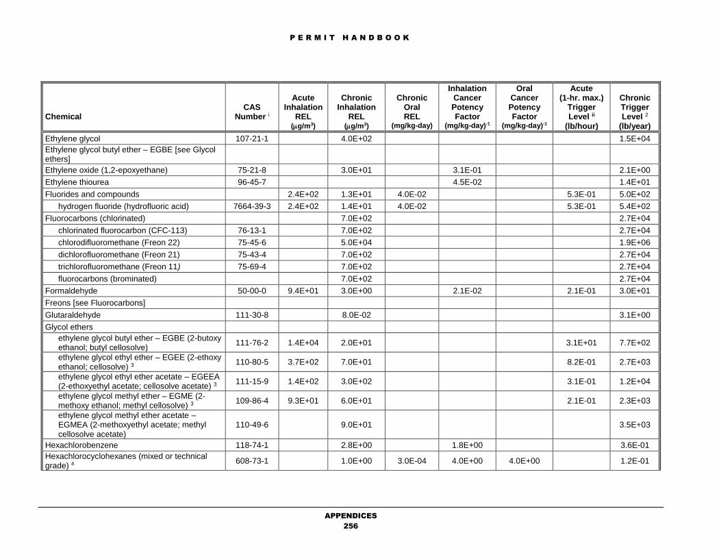
P E R M I T H A N D B O O K
APPENDICES
256
Inhalation Oral Acute Acute Chronic Chronic Cancer Cancer (1-hr. max.) Chronic CAS Inhalation Inhalation Oral Potency Potency Trigger Trigger Chemical Number i REL REL REL Factor Factor Level ii Level 2 (g/m3) (g/m3) (mg/kg-day) (mg/kg-day)-1 (mg/kg-day)-1 (lb/hour) (lb/year)
Ethylene glycol 107-21-1 4.0E+02 1.5E+04
Ethylene glycol butyl ether – EGBE [see Glycol ethers]
Ethylene oxide (1,2-epoxyethane) 75-21-8 3.0E+01 3.1E-01 2.1E+00
Ethylene thiourea 96-45-7 4.5E-02 1.4E+01
Fluorides and compounds 2.4E+02 1.3E+01 4.0E-02 5.3E-01 5.0E+02
hydrogen fluoride (hydrofluoric acid) 7664-39-3 2.4E+02 1.4E+01 4.0E-02 5.3E-01 5.4E+02
Fluorocarbons (chlorinated) 7.0E+02 2.7E+04
chlorinated fluorocarbon (CFC-113) 76-13-1 7.0E+02 2.7E+04
chlorodifluoromethane (Freon 22) 75-45-6 5.0E+04 1.9E+06
dichlorofluoromethane (Freon 21) 75-43-4 7.0E+02 2.7E+04
trichlorofluoromethane (Freon 11) 75-69-4 7.0E+02 2.7E+04
fluorocarbons (brominated) 7.0E+02 2.7E+04
Formaldehyde 50-00-0 9.4E+01 3.0E+00 2.1E-02 2.1E-01 3.0E+01
Freons [see Fluorocarbons]
Glutaraldehyde 111-30-8 8.0E-02 3.1E+00
Glycol ethers
ethylene glycol butyl ether – EGBE (2-butoxy ethanol; butyl cellosolve)
111-76-2 1.4E+04 2.0E+01 3.1E+01 7.7E+02
ethylene glycol ethyl ether – EGEE (2-ethoxy ethanol; cellosolve) 3
110-80-5 3.7E+02 7.0E+01 8.2E-01 2.7E+03
ethylene glycol ethyl ether acetate – EGEEA (2-ethoxyethyl acetate; cellosolve acetate) 3
111-15-9 1.4E+02 3.0E+02 3.1E-01 1.2E+04
ethylene glycol methyl ether – EGME (2-methoxy ethanol; methyl cellosolve) 3
109-86-4 9.3E+01 6.0E+01 2.1E-01 2.3E+03
ethylene glycol methyl ether acetate – EGMEA (2-methoxyethyl acetate; methyl cellosolve acetate)
110-49-6 9.0E+01 3.5E+03
Hexachlorobenzene 118-74-1 2.8E+00 1.8E+00 3.6E-01
Hexachlorocyclohexanes (mixed or technical grade) 4
608-73-1 1.0E+00 3.0E-04 4.0E+00 4.0E+00 1.2E-01

P E R M I T H A N D B O O K
APPENDICES
257
Inhalation Oral Acute Acute Chronic Chronic Cancer Cancer (1-hr. max.) Chronic CAS Inhalation Inhalation Oral Potency Potency Trigger Trigger Chemical Number i REL REL REL Factor Factor Level ii Level 2 (g/m3) (g/m3) (mg/kg-day) (mg/kg-day)-1 (mg/kg-day)-1 (lb/hour) (lb/year)
Hexachlorocyclohexane, alpha- 4 319-84-6 1.0E+00 3.0E-04 4.0E+00 4.0E+00 1.2E-01
Hexachlorocyclohexane, beta- 4 319-85-7 1.0E+00 3.0E-04 4.0E+00 4.0E+00 1.2E-01
Hexachlorocyclohexane, gamma- (lindane) 4 58-89-9 1.0E+00 3.0E-04 1.1E+00 1.1E+00 4.2E-01
Hexachlorocyclopentadiene 77-47-4 2.4E-01 9.3E+00
Hexane, n- 110-54-3 7.0E+03 2.7E+05
Hydrazine 302-01-2 2.0E-01 1.7E+01 3.8E-02
Hydrochloric acid (hydrogen chloride) 7647-01-0 2.1E+03 9.0E+00 4.6E+00 3.5E+02
Hydrogen bromide [see bromine & compounds]
Hydrogen cyanide (hydrocyanic acid) [see cyanide & compounds]
Hydrogen fluoride (hydrofluoric acid) [see fluorides & compounds]
Hydrogen selenide [see selenium compounds]
Hydrogen sulfide 7783-06-4 4.2E+01 1.0E+01 9.3E-02 3.9E+02
Isophorone 78-59-1 2.0E+03 7.7E+04
Isopropyl alcohol (isopropanol) 67-63-0 3.2E+03 7.0E+03 7.1E+00 2.7E+05
Lead and compounds (inorganic) 4 7439-92-1 4.2E-02 8.5E-03 5.4E+00
lead acetate 4 301-04-2 4.2E-02 8.5E-03 5.4E+00
lead phosphate 4 7446-27-7 4.2E-02 8.5E-03 5.4E+00
lead subacetate 4 1335-32-6 4.2E-02 8.5E-03 5.4E+00
Lindane [see hexachlorocyclohexane, gamma]
Maleic anhydride 108-31-6 7.0E-01 2.7E+01
Manganese and compounds 7439-96-5 2.0E-01 7.7E+00
Mercury and compounds (inorganic) 4 7439-97-6 1.8E+00 9.0E-02 3.0E-04 4.0E-03 5.6E-01
mercuric chloride 4 7487-94-7 1.8E+00 9.0E-02 3.0E-04 4.0E-03 5.6E-01
Mercury and compounds (organic)
methyl mercury 593-74-8 1.0E+00 3.9E+01
Methanol (methyl alcohol) 67-56-1 2.8E+04 4.0E+03 6.2E+01 1.5E+05

P E R M I T H A N D B O O K
APPENDICES
258
Inhalation Oral Acute Acute Chronic Chronic Cancer Cancer (1-hr. max.) Chronic CAS Inhalation Inhalation Oral Potency Potency Trigger Trigger Chemical Number i REL REL REL Factor Factor Level ii Level 2 (g/m3) (g/m3) (mg/kg-day) (mg/kg-day)-1 (mg/kg-day)-1 (lb/hour) (lb/year)
Methyl bromide (bromomethane) 74-83-9 3.9E+03 5.0E+00 8.6E+00 1.9E+02
Methyl chloroform (1,1,1-trichloroethane) 71-55-6 6.8E+04 1.0E+03 1.5E+02 3.9E+04
Methyl ethyl ketone (MEK) (2-butanone) 78-93-3 1.3E+04 1.0E+03 2.9E+01 3.9E+04
Methyl isocyanate 624-83-9 1.0E+00 3.9E+01
Methyl mercury [see mercury & compounds]
Methyl methacrylate 80-62-6 9.8E+02 3.8E+04
Methyl tertiary-butyl ether (MTBE) 1634-04-4 8.0E+03 1.8E-03 3.6E+02
Methylene bis (2-chloroaniline), 4,4’- (MOCA) 101-14-4 1.5E+00 4.3E-01
Methylene chloride (dichloromethane) 75-09-2 1.4E+04 4.0E+02 3.5E-03 3.1E+01 1.8E+02
Methylene dianiline, 4,4’- (and its dichloride) 4 101-77-9 2.0E+01 1.6E+00 1.6E+00 4.1E-01
Methylene diphenyl isocyanate 101-68-8 7.0E-01 2.7E+01
Michler's ketone (4,4’-bis(dimethylamino)benzophenone)
90-94-8 8.6E-01 7.4E-01
Mineral fibers (<1% FREE SILICA) 2.4E+01 9.3E+02
ceramic fibers (man-made) 2.4E+01 9.3E+02
glasswool (man-made fibers) 2.4E+01 9.3E+02
mineral fibers (fine: man-made) 2.4E+01 9.3E+02
rockwool (man-made fibers) 2.4E+01 9.3E+02
slagwool (man-made fibers) 2.4E+01 9.3E+02
Naphthalene [see polycylcic aromatic hydrocarbons]
Nickel and compounds 4 (values also apply to:) 7440-02-0 6.0E+00 5.0E-02 5.0E-02 9.1E-01 1.3E-02 7.3E-01
nickel acetate 4 373-02-4 6.0E+00 5.0E-02 5.0E-02 9.1E-01 1.3E-02 7.3E-01
nickel carbonate 4 3333-39-3 6.0E+00 5.0E-02 5.0E-02 9.1E-01 1.3E-02 7.3E-01
nickel carbonyl 4 13463-39-3 6.0E+00 5.0E-02 5.0E-02 9.1E-01 1.3E-02 7.3E-01
nickel hydroxide 4 12054-48-7 6.0E+00 5.0E-02 5.0E-02 9.1E-01 1.3E-02 7.3E-01
Nickelocene 4 1271-28-9 6.0E+00 5.0E-02 5.0E-02 9.1E-01 1.3E-02 7.3E-01
nickel oxide 4 1313-99-1 6.0E+00 1.0E-01 5.0E-02 9.1E-01 1.3E-02 7.3E-01

P E R M I T H A N D B O O K
APPENDICES
259
Inhalation Oral Acute Acute Chronic Chronic Cancer Cancer (1-hr. max.) Chronic CAS Inhalation Inhalation Oral Potency Potency Trigger Trigger Chemical Number i REL REL REL Factor Factor Level ii Level 2 (g/m3) (g/m3) (mg/kg-day) (mg/kg-day)-1 (mg/kg-day)-1 (lb/hour) (lb/year)
nickel refinery dust from the pyrometallurgical process 4
6.0E+00 5.0E-02 5.0E-02 9.1E-01 1.3E-02 7.3E-01
nickel subsulfide 4 12035-72-2 6.0E+00 5.0E-02 5.0E-02 9.1E-01 1.3E-02 7.3E-01
Nitric acid 7697-37-2 8.6E+01 1.9E-01
Nitrobenzene 98-95-3 1.7E+00 6.6E+01
Nitropropane, 2- 79-46-9 2.0E+01 7.7E+02
Nitrosodi-n-butylamine, N- 924-16-3 1.1E+01 5.8E-02
Nitrosodi-n-propylamine, N- 621-64-7 7.0E+00 9.1E-02
Nitrosodiethylamine, N- 55-18-5 3.6E+01 1.8E-02
Nitrosodimethylamine, N- 62-75-9 1.6E+01 4.0E-02
Nitrosodiphenylamine, N- 86-30-6 9.0E-03 7.1E+01
Nitroso-n-methylethylamine, N- 10595-95-6 2.2E+01 2.9E-02
Nitrosomorpholine, N- 59-89-2 6.7E+00 9.6E-02
Nitrosopiperidine, N- 100-75-4 9.4E+00 6.8E-02
Nitrosopyrrolidine, N- 930-55-2 2.1E+00 3.0E-01
Nitrosodiphenylamine, p- 156-10-5 2.2E-02 2.9E+01
Ozone 10028-15-6 1.8E+02 1.8E+02 4.0E-01 7.0E+03
Pentachlorophenol 87-86-5 2.0E-01 1.8E-02 7.7E+00
Perchloroethylene (tetrachloroethylene) 127-18-4 2.0E+04 3.5E+01 2.1E-02 4.4E+01 3.0E+01
Phenol 108-95-2 5.8E+03 2.0E+02 1.3E+01 7.7E+03
Phosgene 75-44-5 4.0E+00 8.8E-03
Phosphine 7803-51-2 8.0E-01 3.1E+01
Phosphoric acid 7664-38-2 7.0E+00 2.7E+02
Phosphorus (white) 7723-14-0 7.0E-02 2.7E+00
Phthalic anhydride 85-44-9 2.0E+01 7.7E+02
PCBs (polychlorinated biphenyls) [low risk] 4, vii 1336-36-3 1.2E+00 2.0E-05 7.0E-02 7.0E-02 8.0E-01
PCBs (polychlorinated biphenyls) [high risk] 4, 7 1336-36-3 1.2E+00 2.0E-05 2.0E+00 2.0E+00 2.8E-02

P E R M I T H A N D B O O K
APPENDICES
260
Inhalation Oral Acute Acute Chronic Chronic Cancer Cancer (1-hr. max.) Chronic CAS Inhalation Inhalation Oral Potency Potency Trigger Trigger Chemical Number i REL REL REL Factor Factor Level ii Level 2 (g/m3) (g/m3) (mg/kg-day) (mg/kg-day)-1 (mg/kg-day)-1 (lb/hour) (lb/year)
Polychlorinated dibenzo-p-dioxins (PCDDs), polychlorinated dibenzofurans (PCDFs), and dioxin-like polychlorinated biphenyls (PCBs) (as 2,3,7,8-PCDD equivalent) 4, viii
See Footnote 8
4.0E-05 1.0E-08 1.3E+05 1.3E+05 5.7E-07
Polycyclic aromatic hydrocarbon (PAH) (as B(a)P-equivalent) 4, ix
See Footnote 9
3.9E+00 1.2E+01 1.1E-02
naphthalene 91-20-3 9.0E+00 1.2E-01 5.3E+00
Potassium bromate [see bromine & compounds]
Propane sultone, 1,3- 1120-71-4 2.4E+00 2.7E-01
Propylene (propene) 115-07-1 3.0E+03 1.2E+05
Propylene glycol monomethyl ether 107-98-2 7.0E+03 2.7E+05
Propylene oxide 75-56-9 3.1E+03 3.0E+01 1.3E-02 6.8E+00 4.9E+01
Selenium and compounds 7782-49-2 2.0E+01 7.7E+02
hydrogen selenide 7783-07-5 5.0E+00 1.1E-02
selenium sulfide 7446-34-6 2.0E+01 7.7E+02
Sodium hydroxide 1310-73-2 8.0E+00 4.8E+00 1.8E-02 1.9E+02
Styrene 100-42-5 2.1E+04 9.0E+02 4.6E+01 3.5E+04
Sulfates 1.2E+02 2.5E+01 2.6E-01 9.7E+02
Sulfuric acid and oleum 7664-93-9 1.2E+02 1.0E+00 2.6E-01 3.9E+01
sulfuric acid 7664-93-9 1.2E+02 1.0E+00 2.6E-01 3.9E+01
sulfur trioxide 7446-71-9 1.2E+02 2.6E-01
oleum 8014-95-7 1.2E+02 1.0E+00 2.6E-01 3.9E+01
Tetrachloroethane, 1,1,2,2- 79-34-5 2.0E-01 3.2E+00
Tetrachlorophenols 25167-83-3 8.8E+01 3.4E+03
Thioacetamide 62-55-5 6.1E+00 1.0E-01
Toluene 108-88-3 3.7E+04 3.0E+02 8.2E+01 1.2E+04
Toluene diisocyantates 26471-62-5 7.0E-02 3.9E-02 2.7E+00
toluene-2,4-diisocyanate 584-84-9 7.0E-02 3.9E-02 2.7E+00
toluene-2,6-diisocyanate 91-08-7 7.0E-02 3.9E-02 2.7E+00

P E R M I T H A N D B O O K
APPENDICES
261
Inhalation Oral Acute Acute Chronic Chronic Cancer Cancer (1-hr. max.) Chronic CAS Inhalation Inhalation Oral Potency Potency Trigger Trigger Chemical Number i REL REL REL Factor Factor Level ii Level 2 (g/m3) (g/m3) (mg/kg-day) (mg/kg-day)-1 (mg/kg-day)-1 (lb/hour) (lb/year)
Trichloroethane, 1,1,1 (see methyl chloroform)
Trichloroethane, 1,1,2- (vinyl trichloride) 79-00-5 5.7E-02 1.1E+01
Trichloroethylene 79-01-6 6.0E+02 7.0E-03 9.1E+01
Trichlorophenol, 2,4,6- 88-06-2 7.0E-02 9.1E+00
Triethylamine 121-44-8 2.8E+03 2.0E+02 6.2E+00 7.7E+03
Urethane (ethyl carbamate) 51-79-6 1.0E+00 6.4E-01
Vanadium Compounds
vanadium (fume or dust) 7440-62-2 3.0E+01 6.6E-02
vanadium pentoxide 1314-62-1 3.0E+01 6.6E-02
Vinyl acetate 108-05-4 2.0E+02 7.7E+03
Vinyl bromide 593-60-2 7.0E+00 2.7E+02
Vinyl chloride (chloroethylene) 75-01-4 1.8E+05 2.6E+01 2.7E-01 4.0E+02 2.4E+00
Vinylidene chloride (1,1-dichloroethylene) 75-35-4 7.0E+01 2.7E+03
Xylenes (mixed isomers) 1330-20-7 2.2E+04 7.0E+02 4.9E+01 2.7E+04
m-xylene 108-38-3 2.2E+04 7.0E+02 4.9E+01 2.7E+04
o-xylene 95-47-6 2.2E+04 7.0E+02 4.9E+01 2.7E+04
p-xylene 106-42-3 2.2E+04 7.0E+02 4.9E+01 2.7E+04
Zinc and compounds 7440-66-6 3.5E+01 1.4E+03
zinc oxide 1314-13-2 3.5E+01 1.4E+03
P E R M I T H A N D B O O K
APPENDICES
262
______________________________________________________________________________________________________________________________________
1 Chemical Abstract Number (CAS): CAS numbers are not available for many chemical groupings and mixtures.
2 Trigger Levels: All trigger levels are presented in scientific notation (i.e., exponential form based on powers of the based number 10.) For example: 4.9E+01 is equivalent to 4.9X101, or 49; 6.6E-02 is equivalent to 6.6X10⁻², or 0.066; and 5.8E+00 is equivalent to 5.8X100, or 5.8.
3 Averaging Period for Non-Cancer Acute Trigger Levels: The averaging period for non-cancer acute trigger levels is generally a one-hour exposure. However, some are based on several hours of exposure. The screening levels for the following substances should be compared to estimated emissions occurring over a time period other than maximum one-hour emissions (e.g., a 4-hour trigger level should be compared to the maximum 4-hour average concentration estimated from the maximum emissions occurring in a 4-hour period). However, for conservative screening purposes, a maximum one-hour emission level can be compare to all acute trigger levels. 4-hour: arsenic and inorganic arsenic compounds 6-hour: benzene, carbon disulfide, ethylene glycol ethyl ether, ethylene glycol ethyl ether acetate, ethylene glycol methyl ether 7-hour: carbon tetrachloride, chloroform
4 Chemicals for Which Multi-Pathway Risks are Assessed: Trigger levels are adjusted to include the impact from default non-inhalation pathways.
5 Asbestos:
The units for the inhalation cancer potency factor for asbestos are (100 PCM fibers/m3)-1. A conversion factor of 100 fibers/0.003 g can be multiplied by a receptor
concentration of asbestos expressed in g/m3. Unless other information necessary to estimate the concentration (fibers/m3) of asbestos at receptors of interest is available, an inhalation cancer potency factor of 220 (mg/kg-day)-1 is available.
6 Diesel Exhaust Particulate Matter: Diesel exhaust particulate matter should be used as a surrogate for all TAC emissions from diesel-fueled compression-ignition internal combustion engines. However, diesel exhaust particulate matter should not be used for other types of diesel-fueled combustion equipment, such as boilers or turbines. For equipment other than diesel-fueled compression-ignition internal combustion engines, emissions should be determined for individual TACs and compared to the appropriate trigger level for each TAC.
7 Polychlorinated Biphenyls: Low Risk: Use in cases where congeners with more than four chlorines comprise less than one-half percent of total polychlorinated biphenyls. High Risk: Use in cases where congeners with more than four chlorines do not comprise less than one-half percent of total polychlorinated biphenyls.

P E R M I T H A N D B O O K
APPENDICES
263
8 Polychlorinated Dibenzo-p-Dioxins (PCDDs), Polychlorinated Dibenzofurans (PCDFs), and Dioxin-like Polychlorinated Biphenyls (PCBs): These substances are PCDDs, PCDFs, and dioxin-like PCBs for which OEHHA has adopted the World Health Organization (WHO97) Toxicity Equivalency Factor (TEF) scheme for evaluating cancer risk due to exposure to samples containing mixtures of PCDDs, PCDFs, and dioxin-like PCBs. PCDDs, PCDFs, and dioxin-like PCBs should be evaluated as PCDD-equivalent. This evaluation process consists of multiplying individual PCDD-, PCDF-, and dioxin-like PCB-specific emission levels with their corresponding TEFs listed below. The sum of these products is the PCDD-equivalent and should be compared to the PCDD-equivalent trigger level. PCDD CAS Number TEF 2,3,7,8-tetrachlorodibenzo-p-dioxin 1746-01-6 1.0 1,2,3,7,8-pentachlorodibenzo-p-dioxin 40321-76-4 1.0 1,2,3,4,7,8-hexachlorodibenzo-p-dioxin 39227-28-6 0.1 1,2,3,6,7,8-hexachlorodibenzo-p-dioxin 57653-85-7 0.1 1,2,3,7,8,9-hexachlorodibenzo-p-dioxin 19408-74-3 0.1 1,2,3,4,6,7,8-heptachlorodibenzo-p-dioxin 35822-46-9 0.01 1,2,3,4,6,7,8,9-octachlorodibenzo-p-dioxin 3268-87-9 0.0001 PCDF CAS Number TEF 2,3,7,8-tetrachlorodibenzofuran 5120-73-19 0.1 1,2,3,7,8-pentachlorodibenzofuran 57117-41-6 0.05 2,3,4,7,8-pentachlorodibenzofuran 57117-31-4 0.5 1,2,3,4,7,8-hexachlorodibenzofuran 70648-26-9 0.1 1,2,3,6,7,8-hexachlorodibenzofuran 57117-44-9 0.1 1,2,3,7,8,9-hexachlorodibenzofuran 72918-21-9 0.1 2,3,4,6,7,8-hexachlorodibenzofuran 60851-34-5 0.1 1,2,3,4,6,7,8-heptachlorodibenzofuran 67562-39-4 0.01 1,2,3,4,7,8,9-heptachlorodibenzofuran 55673-89-7 0.01 1,2,3,4,6,7,8,9-octachlorodibenzofuran 39001-02-0 0.0001 Dioxin-like PCBs (coplanar PCBs) CAS Number TEF PCB 77 (3,3’4,4’-tetrachlorobiphenyl) 32598-13-3 0.0001 PCB 81 (3,4,4’,5-tetrachlorobiphenyl) 70362-50-4 0.0001 PCB 105 (2,3,3’4,4’-pentachlorobiphenyl) 32598-14-4 0.0001 PCB 114 (2,3,4,4’5-pentachlorobiphenyl) 74472-37-0 0.0005 PCB 118 (2,3’,4,4’,5-pentachlorobiphenyl) 31508-00-6 0.0001 PCB 123 (2’,3,4,4’,5-pentachlorobiphenyl) 65510-44-3 0.0001 PCB 126 (3,3’,4,4’,5-pentachlorobiphenyl) 57465-28-8 0.1 PCB 156 (2,3,3’,4,4’,5-hexachlorobiphenyl) 38380-08-4 0.0005 PCB 157 (2,3,3’,4,4’,5’-hexachlorobiphenyl) 69782-90-7 0.0005 PCB 167 (2,3’,4,4’,5,5’-hexachlorobiphenyl) 52663-72-6 0.00001 PCB 169 (3,3’,4,4’,5,5’-hexachlorobiphenyl) 32774-16-6 0.01 PCB 170 (2,2’,3,3’,4,4’,5-heptachlorobiphenyl) 35065-30-6 0
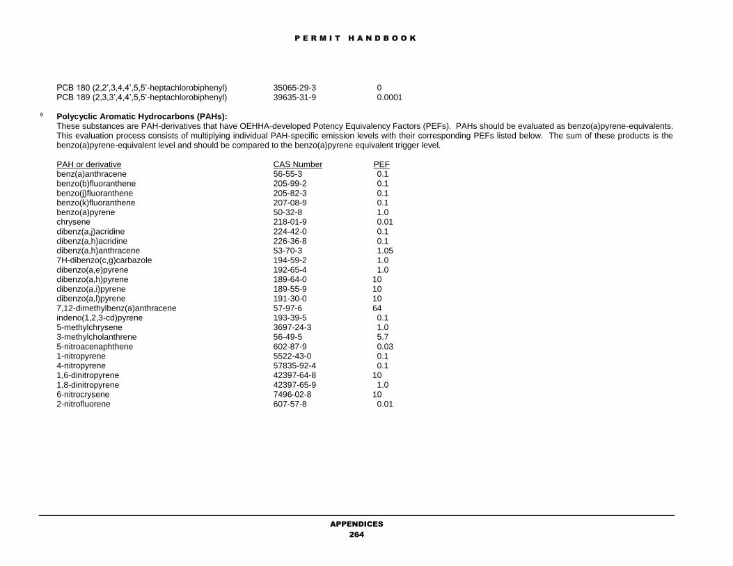
P E R M I T H A N D B O O K
APPENDICES
264
PCB 180 (2,2’,3,4,4’,5,5’-heptachlorobiphenyl) 35065-29-3 0 PCB 189 (2,3,3’,4,4’,5,5’-heptachlorobiphenyl) 39635-31-9 0.0001
9 Polycyclic Aromatic Hydrocarbons (PAHs):
These substances are PAH-derivatives that have OEHHA-developed Potency Equivalency Factors (PEFs). PAHs should be evaluated as benzo(a)pyrene-equivalents. This evaluation process consists of multiplying individual PAH-specific emission levels with their corresponding PEFs listed below. The sum of these products is the benzo(a)pyrene-equivalent level and should be compared to the benzo(a)pyrene equivalent trigger level.
PAH or derivative CAS Number PEF benz(a)anthracene 56-55-3 0.1 benzo(b)fluoranthene 205-99-2 0.1 benzo(j)fluoranthene 205-82-3 0.1 benzo(k)fluoranthene 207-08-9 0.1 benzo(a)pyrene 50-32-8 1.0 chrysene 218-01-9 0.01 dibenz(a,j)acridine 224-42-0 0.1 dibenz(a,h)acridine 226-36-8 0.1 dibenz(a,h)anthracene 53-70-3 1.05 7H-dibenzo(c,g)carbazole 194-59-2 1.0 dibenzo(a,e)pyrene 192-65-4 1.0 dibenzo(a,h)pyrene 189-64-0 10 dibenzo(a,i)pyrene 189-55-9 10 dibenzo(a,l)pyrene 191-30-0 10 7,12-dimethylbenz(a)anthracene 57-97-6 64 indeno(1,2,3-cd)pyrene 193-39-5 0.1 5-methylchrysene 3697-24-3 1.0 3-methylcholanthrene 56-49-5 5.7 5-nitroacenaphthene 602-87-9 0.03 1-nitropyrene 5522-43-0 0.1 4-nitropyrene 57835-92-4 0.1 1,6-dinitropyrene 42397-64-8 10 1,8-dinitropyrene 42397-65-9 1.0 6-nitrocrysene 7496-02-8 10 2-nitrofluorene 607-57-8 0.01

P E R M I T H A N D B O O K
APPENDICES
265
B. DATA FORM GUIDANCE
by M.K. Carol Lee
October 23, 2018
The following instructions are intended to assist permit applicants on the completion of District forms. Use
blue or black ink to complete the forms. Click on the desired items below to find the instructions for each
form:
FORMS
P101B
A
C
CD
F
FF
G
ICE
P
HRSA
S
SC
SS
T
Appendix H

P E R M I T H A N D B O O K
APPENDICES
266
FORM P101B ONE completed P101-B is required per permit application.
DATA FORM FIELD SPECIFIC LINE INSTRUCTIONS
Application Information
Plant No. Enter plant number. Leave blank, if unknown – District will fill in.
NAICS Enter North American Industrial Classification Series. Leave blank, if
unknown – District will fill in.
Business Name Enter name of business.
Equipment Description Enter a brief summary of the permit(s) being requested.
Accelerated Permitting Program Check box, if you qualify for the District’s Accelerated Permitting
Program (see reverse of form for criteria).
Portable Equipment Check box, if you are applying for a portable equipment permit, in
accordance with Regulation 2-1-220.
New Plant Information If the District has not previously assigned a plant number or if existing
plant data requires updating, please complete this section.
Plant Address Enter street address where equipment or operations is to be located.
City Enter city where equipment or operations is to be located.
State Enter CA (for California).
Zip Enter zip code where equipment or operations is to be located.
Mailing Address Enter mailing street address of facility contact. If same as plant
address, leave blank.
City Enter city of facility contact. If same as plant address, leave blank.
State Enter state of facility contact. If same as plant address, leave blank.
Zip Enter zip code of facility contact. If same as plant address, leave
blank.
Plant Contact Enter name of facility contact.
Title Enter title of facility contact.
Telephone Enter telephone number of facility contact.
Fax Enter fax number of facility contact, if any.
E-mail Address Enter e-mail address of facility contact, if any.
Application Contact Information Fill out this section only if it is application contact is different than
facility contact. Note that all correspondence regarding this
application will be sent to the plant contact person unless this section
is filled in. However, all issued permits will be sent to facility contact.
Application Contact Enter name of application contact.
Title/Company Enter title of application contact.
Mailing Address Enter mailing street address of application contact.
City Enter city of application contact.
Telephone Enter telephone number of application contact.
Fax Enter fax number of application contact.
E-mail Address Enter e-mail address of application contact.
Small Business Certification Fill out this section only if you meet the qualification listed. Make
sure to check all the boxes, sign and date this section, if you want to
qualify as a District-defined Small Business.
Accelerated Permitting Program Fill out this section only if you meet the qualifications listed. Make
sure to check all the boxes, sign and date this section, if you want to
certify that you meet the qualifications.

P E R M I T H A N D B O O K
APPENDICES
267
FORM P101B ONE completed P101-B is required per permit application.
DATA FORM FIELD SPECIFIC LINE INSTRUCTIONS
All Applications In general, the District recommends that the applicant provide the
additional information indicated in this section of the form. Make sure
to:
1. Indicate additional information that is provided;
2. Indicate whether the sources in the permit application ARE or ARE
NOT within 1,000 feet of the outer boundary of the nearest school;
3. Indicate NO or YES and by whom if an Environmental Impact
Report other California Environmental Quality Act document has been
prepared; and
4. Sign and date this section.
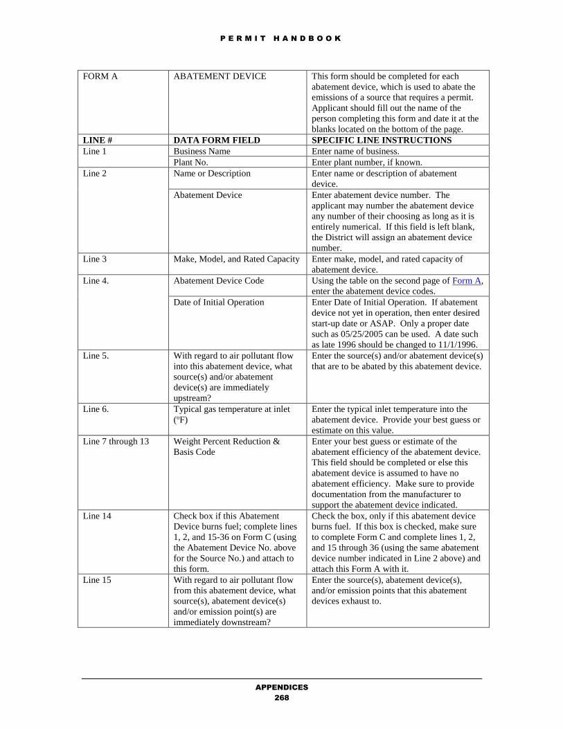
P E R M I T H A N D B O O K
APPENDICES
268
FORM A ABATEMENT DEVICE This form should be completed for each
abatement device, which is used to abate the
emissions of a source that requires a permit.
Applicant should fill out the name of the
person completing this form and date it at the
blanks located on the bottom of the page.
LINE # DATA FORM FIELD SPECIFIC LINE INSTRUCTIONS
Line 1 Business Name Enter name of business.
Plant No. Enter plant number, if known.
Line 2 Name or Description Enter name or description of abatement
device.
Abatement Device Enter abatement device number. The
applicant may number the abatement device
any number of their choosing as long as it is
entirely numerical. If this field is left blank,
the District will assign an abatement device
number.
Line 3 Make, Model, and Rated Capacity Enter make, model, and rated capacity of
abatement device.
Line 4. Abatement Device Code Using the table on the second page of Form A,
enter the abatement device codes.
Date of Initial Operation Enter Date of Initial Operation. If abatement
device not yet in operation, then enter desired
start-up date or ASAP. Only a proper date
such as 05/25/2005 can be used. A date such
as late 1996 should be changed to 11/1/1996.
Line 5. With regard to air pollutant flow
into this abatement device, what
source(s) and/or abatement
device(s) are immediately
upstream?
Enter the source(s) and/or abatement device(s)
that are to be abated by this abatement device.
Line 6. Typical gas temperature at inlet
(oF)
Enter the typical inlet temperature into the
abatement device. Provide your best guess or
estimate on this value.
Line 7 through 13 Weight Percent Reduction &
Basis Code
Enter your best guess or estimate of the
abatement efficiency of the abatement device.
This field should be completed or else this
abatement device is assumed to have no
abatement efficiency. Make sure to provide
documentation from the manufacturer to
support the abatement device indicated.
Line 14 Check box if this Abatement
Device burns fuel; complete lines
1, 2, and 15-36 on Form C (using
the Abatement Device No. above
for the Source No.) and attach to
this form.
Check the box, only if this abatement device
burns fuel. If this box is checked, make sure
to complete Form C and complete lines 1, 2,
and 15 through 36 (using the same abatement
device number indicated in Line 2 above) and
attach this Form A with it.
Line 15 With regard to air pollutant flow
from this abatement device, what
source(s), abatement device(s)
and/or emission point(s) are
immediately downstream?
Enter the source(s), abatement device(s),
and/or emission points that this abatement
devices exhaust to.

P E R M I T H A N D B O O K
APPENDICES
269
FORM C Fuel Combustion Source This form should be completed for each fuel
combustion source. Applicant should fill out the
name of the person completing this form and date it
at the blanks located on the bottom of the page.
LINE # DATA FORM FIELD SPECIFIC LINE INSTRUCTIONS
1 Company Name Enter name of business.
Plant No. Enter plant number, if known.
Source No. Enter source number.
2 Equipment Name &
Number, or Description
Enter Equipment Name and Model, or Description of
Fuel Combustion Source.
3 Make, Model Enter the make and model of the equipment.
4 Date of modification or
initial operation
Enter date of the modification or initial operation of
the source. If unknown, leave blank.
5 SIC No. Enter Standard Industrial Code.
7. Equipment type Indicate by checking the box what the equipment
type. (Check only one item.)
8 Overfire air? Indicate yes or no to this question. If yes, indicate
the percent of overfired air.
9 Fuel gas recirculation? Indicate yes or no to this question. If yes, indicate
the percent of fuel gas recirculation.
10 Air preheat? Indicate yes or no to this question.
11 Low NOx burners? Indicate yes or no to this question.
12 Maximum flame
temperature
Enter the maximum flame temperature in oF.
13 Combustion products Enter the exhaust wet gas flowrate in acfm and the
temperature in oF.
14 Typical operating time Enter the operating hours per day, days per week, and
weeks per year.
15 Typical % of total annual
usage (%)
Enter the percentage of usage between December
through February, March through May, June through
August, and September through November. The
range of acceptable percentages is between 0 and 25.
16 With regard to air
pollutant flow into this
source, what source(s),
abatement device(s) and/or
emission points are
immediately downstream?
Enter the source(s), abatement device(s) and/or
emission points that are to be vented from this
source.
SECTION A Complete one line in Section A for each fuel used.
Please use the units at the bottom of each table. N/A
means “Not Applicable”
SECTION B Section B is OPTIONAL.

P E R M I T H A N D B O O K
APPENDICES
270
FORM
CD
COATER DATA
WORKSHEET
This form should be completed for each coating
source or grouping of coating sources. Applicant
should fill out the name of the person completing
this form and date it at the blanks located on the
bottom of page.
LINE # DATA FORM FIELD SPECIFIC LINE INSTRUCTIONS
1 Business Name Enter name of business.
2 Make, Model, and Rated
Capacity of Equipment
Enter make, model, and rated capacity of equipment.
3 Year equipment was
installed
Enter date equipment was installed. If not yet
installed, indicate so.
4 Typical operating time Enter the operating hours per day, days per week,
and weeks per year.
5 Description of typical
products coated
Enter description of typical products coated.
6 Items Coated Indicate by checking boxes whether metal, plastic,
or wood is coated. Check all that apply.
7 through
11
Type of Coater Indicate by checking box whether the source is a
Spray Booth, Roller Coater, Flow Coater, Dipping
operation, or other. If other, fill in the blank to
indicate what other is.
12
through
17
Spraying Method Indicate by checking box whether the spraying
method is air-atomized, air-assisted, airless,
electrostatic (air atomized, airless, disc), HVLP, or
other. If other, fill in the blanks to indicate what
others is.
18 Drying Method – Air
Dried
If the drying method is air dried, check the box and
skip lines 19 and 20.
19. Drying/Curing Oven
Electric/Infrared Enter the make, model, and BTU/hr rating, if
Electric/Infrared Oven is used.
Gas fired Enter the make, model, and BTU/hr rating, if Gas
fired oven is used.
20 If more than one oven is
associated with this
coating source, please
indicate how many, and
provide a description for
each
Fill in this blank, if applicable.
Coating Usage Table List the names, makers, and product codes of your
most commonly used coatings. Please estimate the
maximum annual use of each coating as applied
(coating + thinner) in gallons. In the next column,
enter your normal mix ratio in parts paint to parts
thinner. And the VOC Content (lb/gal), if known. If
you need more space, please continue on a sheet of
paper. Provide copies of the Material Safety Data
Sheets for these listed coatings and thinners.
Total maximum usage of
all coatings (gal/yr)
Enter the total number of gallons of all paints used
in one year in this blank space below as an estimate
your maximum annual coating usage. Your permit
will be restricted to this level, so you may want to
overestimate to allow for some growth.

P E R M I T H A N D B O O K
APPENDICES
271
FORM
CD
COATER DATA
WORKSHEET
This form should be completed for each coating
source or grouping of coating sources. Applicant
should fill out the name of the person completing
this form and date it at the blanks located on the
bottom of page.
LINE # DATA FORM FIELD SPECIFIC LINE INSTRUCTIONS
Maximum cleanup solvent
use (gal/yr)
Estimate the maximum amount of solvent you use to
clean your coating equipment. Provide copies of the
Material Safety Data Sheets for these listed cleanup
solvent.
Type of cleanup solvent
used
Enter the type of cleanup solvent used. Provide
copies of the Material Safety Data Sheets for these
listed cleanup solvent.

P E R M I T H A N D B O O K
APPENDICES
272
FORM F Semiconductor
Manufacturing Area
This form should be completed for each
semiconductor manufacturing operation (one
cleanroom environment). Applicant should fill out
the name of the person completing this form and
date it at the blanks located on the bottom of page 1
of this two-page form.
1. Complete Lines 1, 2, 3, 5, and 6 of Data Form F.
2. Add Acetone usages indicated in Part A, Section 1 (Solvent Sinks), Section 2 (Solvent Spray
Stations), Section 3 (Solvent Vapor Stations), and Section 4 (Wipe Cleaning Operation) together
and input that quantity on the Acetone blank on Data Form F.
3. Repeat Step 1 for Butyl Acetate, Chloroflurocarbons, Ethyl Acetate, Ethylene Glycol,
Hexamethyldisilazane, Isopropyl Alcohol (IPA), Methanol, Methyl Ethyl Ketone (MEK),
Methylene Chloride, Trichloroethane, Trichloroethylene, Toluene, Xylene, and Phenol.
4. Add the usages of Solvent Mixtures indicated in Part A, Section 1 (Solvent Sinks) and Section 2
(Solvent Spray Stations) together and input that quantity on the Stripper blank on Data Form F (no
trade names or material code need be specified).
5. Add the usages of Solvent Mixtures indicated in Part A, Section 3 (Solvent Vapor Stations) and
Section 4 (Wipe Cleaning Operations) together and input that quantity on the Other blank on Data
Form F (no material code need be specified).
6. Transpose all data from Part B, Section 1 (Coating Operations) to Maskant # 1, 2, and/or 3 blanks
on Data Form F. Use the Material Safety Data Sheets to complete the composition blanks of Data
Form F.
7. If Solvent-Based Developer usage is indicated, check “negative” for Photoresist Operations in
Data Form F.
8. If no Solvent-Based Developer usage is indicated, check “positive” for Photoresist Operations in
Data Form F.
9. Transpose all data from Part B, Section 2 (Solvent-Based Developer) to Developer # 1, 2, and/or 3
blanks on Data Form F. Use the Material Safety Data Sheets to complete the composition blanks
of Data Form F.
10. Transpose Ammonia usage from Part C, Section 1 (Inorganic Liquids) to Aqueous Ammonia
blank in Data Form F.
11. Transpose Hydrochloric Acid usage from Part C, Section 1 (Inorganic Liquids) to Aqueous
Hydrochloric blank in Data Form F.
12. Transpose Hydrofluoric Acid usage from Part C, Section 1 (Inorganic Liquids) to Aqueous
Hydrofluoric Acid blank in Data Form F.
13. Transpose Nitric Acid usage from Part C, Section 1 (Inorganic Liquids) to Nitric Acid usage blank
in Data Form F.
14. Transpose Arsine usage from Part C, Section 2 (Organic and/or Inorganic Gases) to Arsine usage
blank in Data Form F.
15. Transpose Phosphine usage from Part C, Section 2 (Organic and/or Inorganic Gases) to Phosphine
usage blank in Data Form F.
16. Add remaining gases (other than Arsine and Phospine) usages indicated in Part C, Section 2
(Organic and/or Inorganic Gases) together and input that quantity on the Other Dopant gases blank
in Data Form F.
17. Add all precursor solvents and solvent mixtures indicated in Part B, Section 3 (Other
Miscellaneous Solvent Usage) together and input to the Other Organics (precursor) blank on Data
Form F.
18. Add all non-precursor solvents and solvent mixtures indicated in Part B, Section 3 (Other
Miscellaneous Solvent Usage) together and input to the Other Organics (non-precursor) blank on
Data Form F.

P E R M I T H A N D B O O K
APPENDICES
273
FORM FF Semiconductor
Manufacturing Operations
This form should be completed for each
semiconductor manufacturing operation (one
cleanroom environment). Applicant should fill out
the name of the person completing this form and
date it at the blanks located on the bottom of page 1
of this two-page form.
LINE # DATA FORM FIELD SPECIFIC LINE INSTRUCTIONS
Plant No. Enter plant number, if known.
Business Name Enter name of business.
Source No. Enter source number.
Source Description Enter source description.
Initial Date of Operation Enter date of initial operation of equipment. If
source is not yet in operation, indicate desired
startup date or “ASAP” (as soon as possible). Only
a proper date such as 05/25/2005 can be used. A
date such as late 1996 should be changed to
11/1/1996.
Part A –
Solvent
Cleaning
Operations
Solvent Sinks
Solvent Spray Stations
Solvent Vapor Stations
Wipe Cleaning Operations
Maximum annual throughput is the amount of
material that will appear as a permit condition limit.
The usage limit should be set high enough so that it
is not likely to be exceeded while taking into
consideration District BACT, offset, and toxics
requirements. Enter material code for type of
solvent, if known. Make sure to include Material
Safety Data Sheets for solvent mixtures.
Part B –
Coating
Operations
Photoresist
Solvent-Based Developer
Other Miscellaneous
Solvent Usage
Maximum annual throughput is the amount of
material that will appear as a permit condition limit.
The usage limit should be set high enough so that it
is not likely to be exceeded while taking into
consideration District BACT, offset, and toxics
requirements. Enter material code for type of
solvent, if known. Make sure to include Material
Safety Data Sheets for compounds.
Part C –
Other
Operations
Involving
Materials
That Are
Toxic
Inorganic Liquids
Organic and/or Inorganic
Gases
Maximum annual throughput is the amount of
material that will appear as a permit condition limit.
The usage limit should be set high enough so that it
is not likely to be exceeded while taking into
consideration District BACT, offset, and toxics
requirements. Enter material code for type of
solvent, if known.
Compliance Determination
Worksheet
Completion required for those sections that exist in
fab area source.

P E R M I T H A N D B O O K
APPENDICES
274
FORM G General Air Pollution
Source
This form should be completed for each source.
Applicant should fill out the name of the person
completing this form and date it at the blanks located
on the bottom of the page.
LINE # DATA FORM FIELD SPECIFIC LINE INSTRUCTIONS
1 Business Name Enter name of business.
Plant No. Enter plant number, if known.
2 SIC No. Enter Standard Industrial Code.
Date of Initial Operation
(new)
Enter date of initial operation of equipment. If
source is not yet in operation, indicate desired startup
date or “ASAP” (as soon as possible).
3 Name or Description Enter name or description of source.
Source No. Enter source number. If this is a new source, the
applicant may select a number of their choosing. If
this is for a modification of an existing source, write
in the assigned source number.
4 Make, Model, and Rated
Capacity of Equipment
Enter make, model, and rated capacity of equipment.
5 Process Code Enter Process Code (see Tables G-1 through G-7).
Material Code Enter Material Code.
Usage Unit Enter usage unit (see Material Code table for usage
unit).
6 Total throughput, last 12
months
Enter MAXIMUM projected, annual total throughput
in the usage unit indicated in Line 5.
Maximum operating rate Enter the MAXIMUM operating rate per usage unit
indicated in Line 5.
7 Typical % of total annual
usage (%)
Enter the percentage of usage between December
through February, March through May, June through
August, and September through November. The
range of acceptable percentages is between 0 and 25.
8 Typical operating time Enter the operating hours per day, days per week, and
weeks per year.
9 For batch or cyclic
processes
If applicable, enter the minutes per cycle and the
minutes between cycles.
10 Exhaust gases from source If available, enter the exhaust wet gas flowrate in
cubic feet per minute and the flowrate temperature.
Approximate water vapor
content
If available, enter the volume % of water vapor
content.
EMISSION FACTORS If known (by applicant), enter the emission factor and
basis codes (see second page of G form for basis
codes) for the pollutant, if it is emitted from the
source. DO NOT CHECK THE BOX and enter all
emission factors prior to any abatement.
11 Particulate
12 Organics
13 Nitrogen Oxides (as NO2)
14 Sulfur Dioxide
15 Carbon Monoxide
16 Other If applicable, fill in what Other is.
17 Other If applicable, fill in what Other is.

P E R M I T H A N D B O O K
APPENDICES
275
FORM G General Air Pollution
Source
This form should be completed for each source.
Applicant should fill out the name of the person
completing this form and date it at the blanks located
on the bottom of the page.
18 With regard to air
pollutant flow into this
source, what source(s),
abatement device(s) and/or
emission points are
immediately downstream?
Enter the source(s), abatement device(s) and/or
emission points that are to be vented from this
source.
FORM
ICE
Internal Combustion
Engines
This form should be completed for each internal
combustion engine. Applicant should fill out the name
of the person completing this form and date it at the
blanks located on the bottom of page 2 of this two-
page form.
LINE # DATA FORM FIELD SPECIFIC LINE INSTRUCTIONS
1 SUMMARY Check the box that applies to the engine:
New Construction – engine installed or to be installed
on or after September 1, 2001;
Modification – changes to engine which already has a
District permit;
Loss of Exemption – engine installed before
September 1, 2001.
Company Name Enter name of business.
Plant No. Enter plant number, if known.
Source Description Enter source description.
Source No. Enter source number.
Initial Date of Operation Enter date of initial operation of equipment. If source
is not yet in operation, indicate desired startup date or
“ASAP” (as soon as possible). Only a proper date
such as 05/25/2005 can be used. A date such as late
1996 should be changed to 11/1/1996.
Operating Schedule Should give the total number of hours allowed for
testing. For example, 20 hours could be represented as
1 hr per day, 1 day per week, 20 weeks per year.
2 ENGINE
INFORMATION
Check the box if the engine is portable as defined by
Regulation 2-1-413.
Engine Type Check the box that applies. 4 cycle is the same as 4
stroke. Most engines are 4 stroke but there are a small
number of 2 stroke in use.
Engine Manufacturer Enter the engine manufacturer and not the generator
set manufacturer.
EPA/CARB Engine
Family Name
Should be entered for any engine later than the year
2000. Could be found on the ARB website
(https://www.arb.ca.gov/msprog/offroad/cert/cert.php).
Engine Displacement Enter the engine displacement in cubic inches.
Maximum rated output
(bhp)
Enter the maximum rated output in brake horsepower.
The engine displacement in cubic inches is greater
than the maximum rated output in bhp.
Typical load as % of bhp
rating
Enter typical load as percentage of brake horsepower.
Is this an
emergency/standby
engine?
Check the box that applies.

P E R M I T H A N D B O O K
APPENDICES
276
FORM
ICE
Internal Combustion
Engines
This form should be completed for each internal
combustion engine. Applicant should fill out the name
of the person completing this form and date it at the
blanks located on the bottom of page 2 of this two-
page form.
Certification Check the box that applies. If “None” is checked,
please further check the box that applies. In general,
diesel engines are lean-burn.
Primary Use Check the box that applies. If “Other” is checked,
please fill out blank with what the “Other” is.
3. ABATEMENT DEVICE
INFORMATION
Complete this section only if the engine exhausts to an
add-on abatement device. Check the box if the engine
has more than one add-on abatement device and
complete a separate Form A for the additional
abatement devices.
Abatement device number Enter abatement device number. The applicant may
number the abatement device any number of their
choosing as long as it is entirely numerical. If this
field is left blank, the District will assign an abatement
device number.
Device type Check the box that applies. If “Other” is checked,
please fill out blank with what the “Other” is.
Make, Model, and Rated
Capacity
Enter make, model, and rated capacity of abatement
device.
Abatement device control
efficiencies at typical
operation
Fill in with known data. Use the basis codes listed. In
unknown, leave blank.
4 EMISSION
POINT/STACK
INFORMATION
Check the box if the engine has more than one stack or
has a continuous pollutant emission monitor and
complete a separate Form P for the additional stacks.
Emission point number Enter emission point number, if known. Check box
that applies if it is a new or existing emission point.
An existing emission point is that which the
information is already been processed in a prior permit
application.
Stack outlet height from
ground level
Enter outlet height from ground level in feet.
Diameter of stack outlet or
Outlet cross-section area
Enter diameter of stack outlet in feet or outlet cross –
section area in square inches.
Direction of outlet Check box that applies to indicate whether outlet
direction is horizontal or vertical.
Exhaust rate at typical
operation or Exhaust
temperature at typical
operation
Enter exhaust rate at typical operation in actual cubic
feet per minute.
5 RISK ASSESSMENT
INFORMATION
Complete this section even if a risk screening may not
be required.
Distance from engine to
the property line of the
nearest residence
Enter distance from engine to the property line of the
nearest residence in feet or check box if greater than
one mile.
Distance from engine to
the property line of the
nearest school
Enter distance from engine to the property line of the
nearest school in feet or check box if greater than 1000
feet.
Describe the nearest non-
residential, non-school site
Check box that applies. If “Other”, make sure to
explain what “Other” is.

P E R M I T H A N D B O O K
APPENDICES
277
FORM
ICE
Internal Combustion
Engines
This form should be completed for each internal
combustion engine. Applicant should fill out the name
of the person completing this form and date it at the
blanks located on the bottom of page 2 of this two-
page form.
Distance from engine to
the property line of the
nearest non-residential,
non-school site
Enter distance from engine to the property line of the
nearest non-residential non-school site in feet or check
box if greater than one mile.
6 FUEL DATA
Fuel Code Enter the fuel code:
Diesel Oil (98) Fuel Oil No. 2 (392)
Bio Diesel B100 (815) Bio Diesel B20 Blend (816)
Gasoline (551)
Natural Gas (189) Landfill Gas (511)
Digester Gas (493) Liquid Petroleum
Gas (LPG) (160)
Name Enter the name of the fuel.
Maximum Fuel Usage Enter the maximum fuel usage. Maximum fuel use
rate units: gallons/hr for liquid fuels and SCF/hr for
gaseous fuel. SCF = standard cubic foot
Typical Heat Content Enter heat content and circle the units. If you are
using diesel or natural gas, you may skip this entry.
Heat content units: BTU/gallon for liquid fuels,
BTU/SCF for gaseous fuels.
Sulfur Content Enter sulfur content of fuel. If you are using diesel or
natural gas, you may skip this entry. Sulfur content
units: weight % for liquid fuels, ppmv for gaseous
fuels. (ppmv = parts per million by volume)
Emission Factors Enter emission factors in grams/brakehp-hr, lb/gal,
lb/therm, or lb/SCF.
7 CERTIFICATION Sign certification after reviewing statement.

P E R M I T H A N D B O O K
APPENDICES
278
FORM
HRSA
REQUEST OF
INFORMATION
Risk Screen Analysis
This form should be completed for each source that
emits a Toxic Air Contaminant(s) [or for a group of
sources that exhaust through a common volume
source). You must provide a plot plan (drawn to
scale, if possible) and a local map (aerial photos are
recommended, which clearly demonstrate the
location of your site, the source(s), property lines,
and any surrounding buildings. Label streets,
schools, residences, and other businesses. A good
source of free aerial photos can be found at Google
Maps [Enter the plant address at the “Search the
map” box and click on the “Satellite” box, then
press on the [Search Map] button.]
LINE # DATA FORM FIELD SPECIFIC LINE INSTRUCTIONS
Plant Name Enter name of business.
Plant No. Enter plant number, if known.
Source Description Enter description of source.
Source Number Enter source number, if known.
Emission Point Enter emission point, if known.
SECTION
A
1 Does the source exhaust at
clearly defined emission
point; i.e., a stack or
exhaust pipe?
Answer the questions by checking the appropriate
box. If the answer is NO, you have finished Section
A (the remaining questions in Section A do not
apply), go on to Section B.
2-8 If the answer to Line 1 was YES, answer the
remaining questions by checking the appropriate
boxes or filling the blanks with the answer
requested. After completing Line 8, go on to
Section B.
SECTION
B
1 Is the emission source
located within a building?
Answer the question by checking the appropriate
box. If the answer is NO, you have finished Section
B (the remaining questions in Section B do not
apply), go on to Section C.
2-3 If the answer to Line 1 was YES, answer the
remaining questions by checking the appropriate
boxes or filling the blanks with the answer
requested. After completing Line 3, go on to
Section C.
SECTION
C
Provide building dimensions. Use Line B1 only for
building with source/stack on the roof or with
fugitive emissions inside building. Use Lines B2-
B9 for buildings within 300 feet which are
surrounding the source location. Distances and
direction are optional, IF map and/or aerial photo
are adequately labeled with the locations of
buildings. Make sure to check which units (in feet
or in meters). Provide comments in the blank
provided for any details that need additional
clarification (i.e., list buildings that are co-occupied
by your employees and other workers, residents,
students, etc.). After completing this section, go on
to Section D.

P E R M I T H A N D B O O K
APPENDICES
279
FORM
HRSA
REQUEST OF
INFORMATION
Risk Screen Analysis
This form should be completed for each source that
emits a Toxic Air Contaminant(s) [or for a group of
sources that exhaust through a common volume
source). You must provide a plot plan (drawn to
scale, if possible) and a local map (aerial photos are
recommended, which clearly demonstrate the
location of your site, the source(s), property lines,
and any surrounding buildings. Label streets,
schools, residences, and other businesses. A good
source of free aerial photos can be found at Google
Maps [Enter the plant address at the “Search the
map” box and click on the “Satellite” box, then
press on the [Search Map] button.]
LINE # DATA FORM FIELD SPECIFIC LINE INSTRUCTIONS
SECTION
D
Answer the remaining questions by checking the
appropriate boxes or filling the blanks with the
answer requested. Indicate on maps or aerial photos
the residential and nonresidential areas surrounding
the facility.

P E R M I T H A N D B O O K
APPENDICES
280
FORM P Emission Point This form should be completed for each emission
point. Applicant should fill out the name of the
person completing this form and date it at the blanks
located on the bottom of the page of this one-page
form.
LINE # DATA FORM FIELD SPECIFIC LINE INSTRUCTIONS
Business Name Enter name of business.
Plant No. Enter plant number, if known.
Emission Point No. Enter emission point number, if known.
With regard to air
pollutant flow into this
emission point, what
source(s) and/or abatement
device(s) are immediately
upstream?
Enter the source(s) and/or abatement device(s) that
are to be vented to this emission point.
Exit cross section area Enter the cross-sectional area in square feet.
Height above grade. Enter height above grade in feet.
Effluent Flow From Stack
Actual Wet Gas Flowrate Enter the actual wet gas flow rate in cubic feet per
minute in typical and maximum operating
conditions.
Percent Water Vapor Enter percent water vapor in typical and maximum
operating conditions.
Temperature Enter temperature in typical and maximum
operating conditions.
If this stack is equipped to
measure (monitor) the
emissions of air pollutants
Only answer the next two questions, if the stack is
equipped with a monitor to measure the emissions of
air pollutants.
Is monitoring continuous? Answer yes or no, if monitoring is continuous.
What pollutants are
monitored?
Indicate what pollutants are monitored.

P E R M I T H A N D B O O K
APPENDICES
281
FORM S Surface Coating/Solvent
Source
This form should be completed for each solvent
emitting source. Applicant should fill out the name
of the person completing this form and date it at the
blanks located on the bottom of page 1 of this two-
page form.
LINE # DATA FORM FIELD SPECIFIC LINE INSTRUCTIONS
1 Business Name Enter name of business.
Plant No. Enter plant number, if known.
2 SIC No. Enter Standard Industrial Code.
Date of Initial Operation
(new)
Enter date of initial operation of equipment. If
source is not yet in operation, indicate desired
startup date or “ASAP” (as soon as possible).
Date of start-up
(modification)
Enter date of start-up modification.
3 Name or Description Enter name or description of source.
Source No. Enter source number. If this is a new source, the
applicant may select a number of their choosing. If
this is for a modification of an existing source, write
in the assigned source number.
4 Make, Model, and Rated
Capacity of Equipment
Enter make, model, and rated capacity of equipment.
5 Operating time Enter the operating hours per day, days per week,
and weeks per year.
6 Typical % of total annual
usage (%)
Enter the percentage of usage between December
through February, March through May, June
through August, and September through November.
The range of acceptable percentages is between 0
and 25.
7 Solvent evaporation
emissions at this source
vented directly to:
Indicate by the checking the applicable box, whether
the source is vented to the atmosphere (not through
a stack), sources, abatement devices, or emission
points.
Parts A, B, C, D, E, F, G Indicating by checking ALL applicable box(es) ,
whether the source is one or more of the following:
Part A – coating and graphics art operation;
Part B – coating dryer;
Part C – solvent cleaner;
Part D – graphics art operation;
Part E – fiberglass operation;
Part F – manufacturer of coatings, solvents, etc;
Part G – other solvent uses.
Part A Surface Coater The applicant may leave this area blank, as long as
they have completed a Form CD and provided the
material safety data sheets (MSDS) of the coatings
and cleanup solvents indicated in Form CD. The
District will complete this part for the applicant as
long as Form CD and the MSDS’s have been
provided.
8 Coater type Indicate by checking applicable type of coater
source.
9 If sprayer, check method Indicate by checking method, the type of sprayer
used.
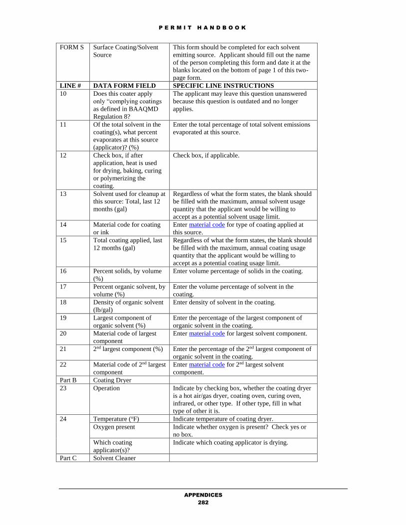
P E R M I T H A N D B O O K
APPENDICES
282
FORM S Surface Coating/Solvent
Source
This form should be completed for each solvent
emitting source. Applicant should fill out the name
of the person completing this form and date it at the
blanks located on the bottom of page 1 of this two-
page form.
LINE # DATA FORM FIELD SPECIFIC LINE INSTRUCTIONS
10 Does this coater apply
only “complying coatings
as defined in BAAQMD
Regulation 8?
The applicant may leave this question unanswered
because this question is outdated and no longer
applies.
11 Of the total solvent in the
coating(s), what percent
evaporates at this source
(applicator)? (%)
Enter the total percentage of total solvent emissions
evaporated at this source.
12 Check box, if after
application, heat is used
for drying, baking, curing
or polymerizing the
coating.
Check box, if applicable.
13 Solvent used for cleanup at
this source: Total, last 12
months (gal)
Regardless of what the form states, the blank should
be filled with the maximum, annual solvent usage
quantity that the applicant would be willing to
accept as a potential solvent usage limit.
14 Material code for coating
or ink
Enter material code for type of coating applied at
this source.
15 Total coating applied, last
12 months (gal)
Regardless of what the form states, the blank should
be filled with the maximum, annual coating usage
quantity that the applicant would be willing to
accept as a potential coating usage limit.
16 Percent solids, by volume
(%)
Enter volume percentage of solids in the coating.
17 Percent organic solvent, by
volume (%)
Enter the volume percentage of solvent in the
coating.
18 Density of organic solvent
(lb/gal)
Enter density of solvent in the coating.
19 Largest component of
organic solvent (%)
Enter the percentage of the largest component of
organic solvent in the coating.
20 Material code of largest
component
Enter material code for largest solvent component.
21 2nd largest component (%) Enter the percentage of the 2nd largest component of
organic solvent in the coating.
22 Material code of 2nd largest
component
Enter material code for 2nd largest solvent
component.
Part B Coating Dryer
23 Operation Indicate by checking box, whether the coating dryer
is a hot air/gas dryer, coating oven, curing oven,
infrared, or other type. If other type, fill in what
type of other it is.
24 Temperature (oF) Indicate temperature of coating dryer.
Oxygen present Indicate whether oxygen is present? Check yes or
no box.
Which coating
applicator(s)?
Indicate which coating applicator is drying.
Part C Solvent Cleaner

P E R M I T H A N D B O O K
APPENDICES
283
FORM S Surface Coating/Solvent
Source
This form should be completed for each solvent
emitting source. Applicant should fill out the name
of the person completing this form and date it at the
blanks located on the bottom of page 1 of this two-
page form.
LINE # DATA FORM FIELD SPECIFIC LINE INSTRUCTIONS
25 Operation Indicate by checking the box, whether the solvent
cleaner is one of the following:
Degreaser – cold cleaner, vapor or conveyorized
degreaser;
Dry Cleaning – used for dry cleaning; OR
Other – used for wipe cleaning and other operations.
Make sure to fill out blank to indicate what the other
operation is.
26 Net solvent usage, total
last 12 months (gal)
Regardless of what the form states, the blank should
be filled with the maximum, annual solvent usage
quantity that the applicant would be willing to
accept as a potential solvent usage limit.
27 Is all solvent used in this
source “complying” as
defined in BAAQMD
Regulation 8?
The applicant may leave this question unanswered
because this question is outdated and no longer
applies.
28 Solvent used most:
Material Code Enter material code for solvent used most.
Density (lb/gal) Enter density for solvent used most.
Percent of Total Used (%) Enter percentage of solvent that this solvent
represents in the total of all solvents used.
29 Solvent used 2nd most
Material Code Enter material code for solvent used 2nd most.
Density (lb/gal) Enter density for solvent used 2nd most.
Percent of Total Used (%) Enter percentage of solvent that this solvent
represents in the total of all solvents used.
Part D Printing Press
30 Type Indicate by checking the box whether the printing
press is a flexographic, rotogravure, letterpress,
lithographic, silk screen, or other. If other, fill out
the blank to indicate what other is.
31 Total ink used, last 12
months (in lb or gal or
tons)
Regardless of what the form states, the blank should
be filled with the maximum, annual ink usage
quantity that the applicant would be willing to
accept as a potential ink usage limit.
32 Total solvent used for
cleanup, etc., last 12
months (gal)
Regardless of what the form states, the blank should
be filled with the maximum, annual cleanup solvent
usage quantity that the applicant would be willing to
accept as a potential solvent usage limit.
Material Code Enter material code for solvent used.
Part E Fiberglass Operation
33 Operation Check the box to indicate whether it is a fiberglass
dip, layup, molding, spray (chopper gun), spray
(other), or other type of operation. If other, fill out
the blank to indicate what other is.
34 Specify resin used Enter the resin name.
Total volume used, last 12
months (gal)
Regardless of what the form states, the blank should
be filled with the maximum, annual resin usage
quantity that the applicant would be willing to
accept as a potential resin usage limit.

P E R M I T H A N D B O O K
APPENDICES
284
FORM S Surface Coating/Solvent
Source
This form should be completed for each solvent
emitting source. Applicant should fill out the name
of the person completing this form and date it at the
blanks located on the bottom of page 1 of this two-
page form.
LINE # DATA FORM FIELD SPECIFIC LINE INSTRUCTIONS
Volume percent styrene
(%)
Enter the percent styrene in the resin.
Volume percent other
volatile organics (%)
Enter the percent other volatile organics in the resin.
35 Specify Catalyst used Enter the catalyst name.
Total volume used, last 12
months (gal)
Regardless of what the form states, the blank should
be filled with the maximum, annual catalyst usage
quantity that the applicant would be willing to
accept as a potential catalyst usage limit.
36 Total solvent used for
cleanup, etc., last 12
months (gal)
Regardless of what the form states, the blank should
be filled with the maximum, annual cleanup solvent
usage quantity that the applicant would be willing to
accept as a potential solvent usage limit.
Material Code Enter material code for solvent used.
Part F Manufacturer of Coatings,
Solvents, etc.
37 Solvent used for cleanup at
this source: Total, last 12
months (gal)
Regardless of what the form states, the blank should
be filled with the maximum, annual cleanup solvent
usage quantity that the applicant would be willing to
accept as a potential solvent usage limit.
Material Code Enter material code for solvent used for cleanup.
38 Material manufactured
(Material Code)
Enter material code for the material that is
manufactured for Highest Production, 2nd Highest
Production, and All Remaining Production.
39 Quantity manufactured,
last 12 months (1,000 gal)
Regardless of what the form states, the blank should
be filled with the maximum, annual quantity of
material manufactured that the applicant would be
willing to accept as a potential throughput limit
manufactured for Highest Production, 2nd Highest
Production, and All Remaining Production. Make
sure that quantity is indicated per 1,000 gallon.
40 Solvent used (Material
Code)
Enter material code for solvent used manufactured
for Highest Production, 2nd Highest Production, and
All Remaining Production.
41 Solvent evaporated during
manufacturing, as volume
% of material produced
Enter volume percentage of solvent evaporated
during manufacturing compared to the material
produced manufactured for Highest Production, 2nd
Highest Production, and All Remaining Production.
Part G Other Solvent Use
42 Solvent evaporated most at
this source
Material Code Enter material code for solvent evaporated most.
Total evaporated, last 12
mo. (gal)
Regardless of what the form states, the blank should
be filled with the maximum, annual quantity of
solvent evaporated most that the applicant would be
willing to accept as a potential limit.
43 Solvent evaporated 2nd
most at this source
Material Code Enter material code for solvent evaporated 2nd most.

P E R M I T H A N D B O O K
APPENDICES
285
FORM S Surface Coating/Solvent
Source
This form should be completed for each solvent
emitting source. Applicant should fill out the name
of the person completing this form and date it at the
blanks located on the bottom of page 1 of this two-
page form.
LINE # DATA FORM FIELD SPECIFIC LINE INSTRUCTIONS
Total evaporated, last 12
mo. (gal)
Regardless of what the form states, the blank should
be filled with the maximum, annual quantity of
solvent evaporated 2nd most that the applicant would
be willing to accept as a potential limit.

P E R M I T H A N D B O O K
APPENDICES
286
FORM
SC
Solvent Cleaning
Operation
This form should be completed for each solvent
cleaning operation source. Applicant should fill out
the name of the person completing this form and
date it at the blanks located on the bottom of page 1.
LINE # DATA FORM FIELD SPECIFIC LINE INSTRUCTIONS
SIC Number Enter Standard Industrial Code.
Plant No. Enter plant number, if known.
1 Business Name Enter name of business.
2 Date of Initial Operation
(new)
Enter date of initial operation of equipment. If
source is not yet in operation, indicate desired
startup date or “ASAP” (as soon as possible).
Source No. Enter source number. If this is a new source, the
applicant may select a number of their choosing. If
this is for a modification of an existing source, write
in the assigned source number.
3 Make, Model, and Rated
Capacity of Equipment
Enter make, model, and rated capacity of equipment.
4 Operating time Enter the operating hours per day, days per week,
and weeks per year.
5 Typical % of total annual
usage (%)
Enter the percentage of usage between December
through February, March through May, June
through August, and September through November.
The range of acceptable percentages is between 0
and 25.
6 Solvent evaporation
emissions at this source
vented directly to:
Indicate by the checking the applicable box, whether
the source is vented to the atmosphere (not through
a stack), sources, abatement devices, or emission
points.
7 Net solvent usage for 12-
month period (gals)
Enter the maximum, annual net solvent usage that
the applicant would be willing to accept as a usage
limit.
8 Solvent used most:
Trade name
Enter the name of the solvent, which is used most.
% of total used Enter percentage of solvent in the total.
9 Solvent used 2nd most:
Trade name
Enter the name of the solvent, which is used 2nd
most.
% of total 2nd used Enter percentage of solvent in the total.
8a Material Code Enter material code for solvent most. District use
only.
Density (lb/gal) Enter density of solvent used most. District use
only.
9a Material Code Enter material code for solvent used 2nd most.
District use only.
Density (lb/gal) Enter density of solvent used 2nd most. District use
only.
10 If this is a wipe cleaning
operation, check box.
Check box, if it is a wipe cleaning operation and
stop. The form is now complete, if this is a wipe
cleaning operation.
11. Container
Length (in) Enter length of container.
Width (in) Enter width of container.
Liquid volume (gal) Enter liquid volume.

P E R M I T H A N D B O O K
APPENDICES
287
FORM
SC
Solvent Cleaning
Operation
This form should be completed for each solvent
cleaning operation source. Applicant should fill out
the name of the person completing this form and
date it at the blanks located on the bottom of page 1.
LINE # DATA FORM FIELD SPECIFIC LINE INSTRUCTIONS
Freeboard height (in) Enter freeboard height. Of open-top vapor
degreasing tanks, the distance from the solvent
vapor-air interface to the top of the degreaser tank.
Of conveyorized degreasing tanks, the distance from
the top of the solvent or solvent vapor-air interface
to the bottom of the lowest opening in the degreaser
tank. Of cold cleaning tanks, the distance from the
top of the solvent or solvent drain to the top of the
tank.
12 Freeboard ratio Enter freeboard ratio = freeboard height/shorter of
length or width
13 General information Check either yes or no
14 Equipment type Check box to indicate source type and go to the
section that is indicated:
Vapor Degreaser – go to Part A
Conveyorized Degreaser – go to Part B
Cold Cleaner – go to Part C
Part A
Lines 15
through
19
Check either yes or no to the questions that apply.
Part B
Lines 20
through
26
Check either yes or no to the questions that apply.
Part C
Lines 27
through
29
Check either yes or no to the questions that apply.

P E R M I T H A N D B O O K
APPENDICES
288
FORM
SS
PRINTER MATERIAL
USAGE INFORMATION
This form should be completed for each printing
source or grouping of printing sources. Applicant
should fill out the name of the person completing
this form and date it at the blanks located on the
bottom of page.
DATA FORM FIELD SPECIFIC LINE INSTRUCTIONS
TABLE Complete the table to provide annual usage
information on a facility-wide basis for each
different type of materials used at the facility.
Indicate whether ink and varnish usages are given in
gallons or pounds. Submit a copy of the Material
Safety Date Sheet (MSDS) for each material
identified below. Be advised that these usage values
will be included as material usage limits in permit
conditions issued with your permit to operate. So,
be sure that annual usage values include allowances
for reasonable growth over the next few years.
Mixed fountain solution formulation Enter the mixed foundation solution formulations
for water: IPA: and fountain concentrate.

P E R M I T H A N D B O O K
APPENDICES
289
FORM T ORGANIC LIQUID
EVAPORATION
This form should be completed for each organic
liquid storage tank. Applicant should fill out the
name of the person completing this form and date it
at the blanks located on the bottom of this form.
LINE # DATA FORM FIELD SPECIFIC LINE INSTRUCTIONS
1 Business Name Enter name of business.
Plant No. Enter plant number, if known.
2 SIC No. Enter Standard Industrial Code.
Source No. Enter source number. If this is a new source, the
applicant may select a number of their choosing. If
this is for a modification of an existing source, write
in the assigned source number.
Date of start-up
(modification)
Enter date of start-up modification.
3 Name or Description Enter name or description of source.
4 Code materials* in order
of highest throughput
*See Material Code Reference List
5 Total throughput (all
materials), last 12 months:
Enter the MAXIMUM total throughput proposed for
this source tank.
6 Typical % of total annual
usage (%)
Enter the percentage of usage between December
through February, March through May, June
through August, and September through November.
The range of acceptable percentages is between 0
and 25.
7 Usage type Indicate by checking the applicable box, whether the
tank is used for a bulk plant (truck/rail car), bulk
plant (marine), vehicle service station,
aircraft/marine servicing, or other. If other, explain
what “other” is.
8 How many
nozzles/loading arms?
If applicable, indicate the number of nozzles/loading
arms.
9 Make and model of
nozzles/loading arms.
If applicable, indicate the make and model of the
nozzles/loading arms.
10 Nozzle/arm loads tank by If applicable, indicate by checking the applicable
box, whether the nozzle/arms load the tank by
splash fill, submerged fill, part splash, or part
submerged.
11 Upon loading, vapor space
in tank(s) is
Indicate by checking the applicable box, whether the
vapor space in the tank is vented to the atmosphere
or collected by nozzle/arm and sent to an abatement
device. If sent to an abatement device, indicate the
Abatement Device number.
12 Annual Average Indicate the storage vapor pressure in psia or tank
temperature in oF and Reid Vapor Pressure (psia).
13 Highest v.p. of all
materials stored
Indicate highest vapor pressure in psia or high tank
temperature in oF and Reid Vapor Pressure (psia).
14 Highest oAPI of all
materials stored
Indicate highest oAPI of all materials stored.
15 Tank Type Indicate by checking the applicable box, whether the
tank is an underground, fixed roof, internal floating
roof, floating roof, pressure, or other type. If other
is checked, indicate what that other is.
16 Tank Volume Indicate the volume of the tank in thousand gallons
or thousand barrels (1 barrel = 42 gallons).
17 Tank Diameter Indicate the tank diameter in feet.

P E R M I T H A N D B O O K
APPENDICES
290
FORM T ORGANIC LIQUID
EVAPORATION
This form should be completed for each organic
liquid storage tank. Applicant should fill out the
name of the person completing this form and date it
at the blanks located on the bottom of this form.
LINE # DATA FORM FIELD SPECIFIC LINE INSTRUCTIONS
Height or length Indicate the tank height or length in feet.
FIXED ROOF TANKS
ONLY
Fill this section out only if the tank is a fixed roof
tank..
18 Maximum fill rate Indicate the maximum fill rate in gallons per hour or
barrels per hour (1 barrel = 42 gallons).
19 Average height or vapor
space
Indicate the average height or vapor space in feet.
Highest head space
reactivity
Indicate the highest head space reactivity.
20 Emissions vent to what
source(s) and/or abatement
devices(s)
If applicable, Indicate whether the emissions from
the tank vent to another source or abatement device.
21 Do all gauging/sampling
devices have gas-tight
covers?
Indicate yes or no to this question.
22 Paint color Indicate by checking the box, what color the tank is.
23 Paint condition Indicate by checking the box, what condition the
paint is in.
FLOATING ROOF
TANKS ONLY
Fill this section out only if the tank is a floating roof
tank.
24 Shell Type Indicate by checking, what the tank shell type is.
25 Seal Type Indicate by checking, what the seal type is.
26 Maximum withdrawn rate Indicate the maximum withdrawal rate in gallons
per hour or barrels per hour (1 barrel = 42 gallons).
27 Do all gauging/sampling
devices enter below liquid
level and have gas-tight
covers?
Indicate yes or no to this question.
28 Roof type Indicate by checking, what the roof type of the tank
is.
Is emergency roof drain at
least 90% covered?
Indicate yes or no to this question.

P E R M I T H A N D B O O K
APPENDICES
291
Appendix
H
ENVIRONMENTAL
INFORMATION FORM
This form should be completed for a permit
application which is non-ministerial, categorically
exempt, or having a potentially significant impact.
Person completing the form should complete the
certification at the end of this form.
LINE # DATA FORM FIELD SPECIFIC LINE INSTRUCTIONS
Date Filed Date completing this form.
1-7 General Information Fill in the general information requested, unless it is
not applicable. Provide as much detail as possible..
8-20 Project Description Provide information requested, unless it is not
applicable. Provide as much detail as possible.
Provide attachments, if needed.
21-32 Project Description Please check “Yes” or “No”. Provide a detailed
written explanation for any item(s) checked “Yes”.
Provide attachments, if needed.
33-34 Environmental Setting Provide information requested. Provide as much
detail as possible. Provide attachments, if needed.

P E R M I T H A N D B O O K
APPENDICES
292
C. FEE CALCULATION GUIDANCE
by M.K. Carol Lee
October 23, 2018
State law authorizes the District to assess fees to generate revenue to cover regulatory program activity
costs (i.e., the District’s direct and indirect expenditures for personnel, services and supplies, and capital
outlay, related to implementing and enforcing air quality programs affecting stationary sources of air
pollution). The largest portion of fees is collected, per Health and Safety Code Section 42311(a) and (f),
which allows the District to impose permit fees sufficient to cover the full costs of programs, related to
permitted sources. The District's Regulation 3 contains the fee schedule for new and renewed permits.
Typically, the permit fees for a new/modified source include a filing fee (defined in Regulation 3-203),
initial fee (defined in Regulation 3-204), and annual permit to operate (PO) fee (defined in Regulation 3-
207) for the source to be permitted/modified (per Regulation 3-302). However, additional fees are required
if the source triggers a risk screening (per Regulation 3-329), school public notice (per Regulation 3-318),
and/or if the source has been constructed or modified without a permit (per Regulation 3-310) such that late
(per Regulation 3-310) and back fees (per Regulation 3-303) may apply. In addition, fees are also required
for abatement devices, which are, permitted alone (per Regulation 3-302.3), alterations of a source (per
Regulation 3-304), changes of conditions (per Regulation 3-306), loss of exemption (per Regulation 3-
310.2), and banking of emissions reduction credit (per Regulation 3-311). In specific cases, a toxic
inventory fee (per Regulation 3-320) may apply. For those applicants that qualify, a small business
(defined in Regulation 3-209) discount may apply. In short, calculating permit fees accurately can be
challenging. A permit fee calculation decision tree has been developed to assist in determining the types of
fees required for various permit scenarios.
After determining the types of fees required (see permit fee calculation decision tree ), use the table below
to determine the applicable fee schedule to calculate the fees for Initial, PO (permit to operate), RSF (risk
screening fee), toxic surcharge and/or TIF (toxic inventory fee), if applicable. Once the Initial and PO
(w/toxic surcharges and inventory, if applicable) fees are calculated, the Late and Back fees can be
determined. The Late fees are equal in amount to the Initial fees; and the Back fees are PO fees with toxic
surcharges and inventory fees prorated from the effective date of the permit requirements, not to exceed 5
years.
Permit
Handbook
Chapter #
Permit Handbook
Source Category
Applicable
Regulation 3
Fee Schedule
Notes of Interest
2 Combustion
Equipment
2.1 Boilers, Steam
Generators &
Process Heaters
B – Combustion of
Fuel
Fees are based on maximum gross
combustion capacity (MMBT/hr).
2.2 (deleted)
2.3 Internal
Combustion
Engines
2.3.1 Stationary Diesel
Engines
B – Combustion of
Fuel
Fees are based on maximum gross
combustion capacity (MMBT/hr).
2.3.2 Stationary Natural
Gas Engines
B – Combustion of
Fuel
Fees are based on maximum gross
combustion capacity (MMBT/hr).
2.3.3 Portable Diesel
Engines
B – Combustion of
Fuel
Fees are based on maximum gross
combustion capacity (MMBT/hr).
3 Petroleum Industry
3.1 Bulk Loading
Facilities
D – Gasoline
Transfer at Gasoline
Dispensing
Facilities, Bulk
Plants and Terminals
Fees are based on the number of single and
multi-product arms.

P E R M I T H A N D B O O K
APPENDICES
293
Permit
Handbook
Chapter #
Permit Handbook
Source Category
Applicable
Regulation 3
Fee Schedule
Notes of Interest
3.2 Gasoline
Dispensing
Facilities
D – Gasoline
Transfer at Gasoline
Dispensing
Facilities, Bulk
Plants and Terminals
Note that this source is NOT eligible for
Small Business Discount, per 3-302.1. Fees
are based on the number of single and
multi-product nozzles.
3.3 Oil Water
Separators
G-1, excluding oil-
water separators at
petroleum refineries;
G-2 for petroleum
refineries
See Schedule F for fees. Note that this
source is NOT eligible for Small Business
Discount, per 3-302.1.
3.4 Petroleum Refinery
Fugitive Emissions
G-3 See Schedule F for fees. Note that this
source is NOT eligible for Small Business
Discount, per 3-302.1.
3.5 Natural Gas
Facilities
B – Combustion of
Fuell for compressor
engines;
C – Stationary
Containers for the
Storage of Organic
Liquid for
condensate tanks;
and
F – Miscellaneous
Sources for
dehydrators
Fees are based on maximum gross
combustion capacity (MMBT/hr).
Fees are based on container volume.
See Schedule F for fees.
4. Organic Liquid
Storage Tanks
C – Stationary
Containers for the
Storage of Organic
Liquid
Fees are based on container volume.
5 Coating Operations
5.1 Spray Booths &
Spray Guns
E – Solvent
Evaporating Source
Fees are based on net maximum amount of
organic solvent processed through sources
on an annual basis.
5.2 Coating and Ink
Manufacturing
E – Solvent
Evaporating Source
Fees are based on net maximum amount of
organic solvent processed through sources
on an annual basis.
5.3 Graphic Arts
Printing and
Coating Operations
E – Solvent
Evaporating Source
Fees are based on net maximum amount of
organic solvent processed through sources
on an annual basis.
6 Solvent Cleaning
Operations
E – Solvent
Evaporating Source
Fees are based on net maximum amount of
organic solvent processed through sources
on an annual basis.
6.1 Cold Solvent
Cleaning
E – Solvent
Evaporating Source
Fees are based on net maximum amount of
organic solvent processed through sources
on an annual basis.
6.2 Vapor and
Conveyorized
Solvent Cleaning
E – Solvent
Evaporating Source
Fees are based on net maximum amount of
organic solvent processed through sources
on an annual basis.
6.3 Wipe Cleaning
Operatons
E – Solvent
Evaporating Source
Fees are based on net maximum amount of
organic solvent processed through sources
on an annual basis.
7 Electronic &
Semiconductor
Industry

P E R M I T H A N D B O O K
APPENDICES
294
Permit
Handbook
Chapter #
Permit Handbook
Source Category
Applicable
Regulation 3
Fee Schedule
Notes of Interest
7.1 Circuit Board
Manufacturing
E – Solvent
Evaporating Source
Fees are based on net maximum amount of
organic solvent processed through sources
on an annual basis.
7.2 Electronic
Assembly & Wave
Soldering
E – Solvent
Evaporating Source
Fees are based on net maximum amount of
organic solvent processed through sources
on an annual basis.
7.3 Flexible and Rigid
Disk Manufacturing
E – Solvent
Evaporating Source
Fees are based on net maximum amount of
organic solvent processed through sources
on an annual basis.
7.4 Semiconductor
Manufacturing
Operation
H – Semiconductor
and Related
Operations
Fees are based on net maximum amount of
organic solvent processed through solvent
cleaning and coating operations.
8 Waste Processing
Industry
8.1 (deleted)
8.2 Wastewater
Treatment Facilities
G-1 See Schedule F for fees. Note that this
source is NOT eligible for Small Business
Discount, per 3-302.1.
9 Soil/Water
Remediation
9.1 Airstripping G-1; Schedule F for
Sub-Slab
Depressurizaton
See Schedule F for fees. Note that this
source is NOT eligible for Small Business
Discount, per 3-302.1.
9.2 Soil Vapor
Extraction –
gasoline
G-1; Schedule F for
Sub-Slab
Depressurizaton
See Schedule F for fees. Note that this
source is NOT eligible for Small Business
Discount, per 3-302.1.
9.3 (deleted)
10 Toxic Emitting
Operations
10.1 Chrome Plating G-1 See Schedule F for fees. Note that this
source is NOT eligible for Small Business
Discount, per 3-302.1.
10.2 Ethylene Oxide
Sterilizers
G-1 See Schedule Ffor fees. Note that this
source is NOT eligible for Small Business
Discount, per 3-302.1.
10.3 (deleted)
10.4 Petroleum Solvent
Dry Cleaning
I – Dry Cleaners
May also be subject
to Schedule N –
Toxic Inventory Fees
The TIF are based on total facility toxic
emissions. TIF would only apply if adding
unpermitted source would increase fees.
10.5 Synthetic Solvent
Dry Cleaning
I – Dry Cleaners
May also be subject
to Schedule N –
Toxic Inventory Fees
The TIF are based on total facility toxic
emissions. TIF would only apply if adding
unpermitted source would increase fees.
11 Miscellaneous
Operations
11.1 Abrasive Blasting F – Miscellaneous
Sources
See Schedule F for fees.
11.2 Asphalt (Hot Mix)
Plants
G-2 See Schedule F for fees. Note that this
source is NOT eligible for Small Business
Discount, per 3-302.1.
11.3 Coffee Roasting
Operations
F – Miscellaneous
Sources
See Schedule F for fees.
11.4 Cooling Towers F – Miscellaneous See Schedule F for fees.

P E R M I T H A N D B O O K
APPENDICES
295
Permit
Handbook
Chapter #
Permit Handbook
Source Category
Applicable
Regulation 3
Fee Schedule
Notes of Interest
Sources
11.5 Concrete Batch
Plants
G-1for Crushers or
Grinders;
G-2 for Concrete or
Cement Batching
Operations – Mixers;
F for other sources
There is a specific policy for the grouping
of sources and the calculation of fees at
concrete batch plants and
quarrying/crushing operations.
See Schedule F for fees. Note that this
source is NOT eligible for Small Business
Discount, per 3-302.1.
11.6 Crematories G-1 See Schedule F for fees. Note that this
source is NOT eligible for Small Business
Discount, per 3-302.1.
11.7 Crushing and
Grinding
G-1 for Crushers or
Grinders;
G-2 for Concrete or
Cement Batching
Operations – Mixers;
F for other sources
There is a specific policy for the grouping
of sources and the calculation of fees at
concrete batch plants and
quarrying/crushing operations.
See Schedule F for fees. Note that this
source is NOT eligible for Small Business
Discount, per 3-302.1.
11.8 (deleted)
11.9 Misc. Organic
Operations
E – Solvent
Evaporating Source
Fees are based on net maximum amount of
organic solvent processed through solvent
cleaning and coating operations.
11.10 Portable Equipment Same as that for
source type if
equipment was
stationary
Same as that for source type if equipment
was stationary
11.11 Polyester Resin
Manufacturing
F – Miscellaneous
Sources
See Schedule F for fees.
11.12 Polyester Resin
Operations
E – Solvent
Evaporating Source
Fees are based on net maximum amount of
organic solvent processed through sources
on an annual basis.
11.13 Tub Grinders F – Miscellaneous
Sources
See Schedule F for fees.
Permit Fee Calculation Decision Tree
For NEW SOURCE
For MODIFIED SOURCE

P E R M I T H A N D B O O K
APPENDICES
296

P E R M I T H A N D B O O K
APPENDICES
297
Fee Calculation Decision Tree for New Source

P E R M I T H A N D B O O K
APPENDICES
298
Fee Calculation Decision Tree for Modified Sources

P E R M I T H A N D B O O K
APPENDICES
299
D. COMPLETENESS DETERMINATION CHECKLIST
by M.K. Carol Lee
July 18, 2006
A COMPLETE permit application shall typically include the following items:
(Basis: Regulation 2-1-202)
1. All required data Forms/worksheets completed – See Data Form Guidance.
2. All required fees paid – See Fee Calculation Guidance.
3. A cover letter, which includes a background description of the proposed project. If the project
involves an assembly line process or other complicated process, diagrams of the process
should also be included with the background description.
4. Significant information needed to calculate emissions, including toxics, from the proposed
source(s).
5. If a Risk Screening is triggered, a completed Risk Screen Analysis form – See Data Form
Guidance.
6. If the proposed source(s) is located within 1000 feet of a school:
a. The required public notification fee paid – See Fee Calculation Guidance; and
b. Identification of all schools within 0.25 mi. of the source(s).
c. Satellite map showing the sources and school boundaries.
7. If the permit is not ministerial as set forth in Regulation 2-1-427:
a. And the District is the lead agency, a completed Appendix H Form – See Data Form
Guidance; or
b. And the District is not the lead agency, any one of the following prepared by or under the
supervision of the lead agency:
i. A Draft or Final Environmental Impact Report (EIR); or
ii. A contract for the preparation of a draft EIR; or
iii. A Negative Declaration; or
iv. A Notice of Preparation of a draft EIR; or
v. A copy of the Initial Study; or
vi. A commitment in writing indicating lead agency role.
8. If PSD is triggered per Regulation 2-2-304, 305, 306, or 308, PSD Modeling Analysis
meeting the requirements of Regulation 2-2-414.
9. If any or all part of the application has been claimed as trade secret:
a. A public copy of application with trade secret information redacted; and
b. For each section of the application that was claimed trade secret, a statement signed by
the applicant identifying the portion of the Government Code Section 6254.7 (d) upon
which the assertion is based and a statement setting forth the basis for this assertion.
Additional information is required if it is an application which triggers
Regulation 2-2 (New Source Review) requirements:
10. For new facilities, which will emit, and for a modification which will increase emissions more
than 100 tons per year of carbon monoxide or 40 tons per year of either precursor organic
compounds or nitrogen oxides, an analysis of alternative sites, sizes, production processes,
and environmental control techniques for such proposed source which demonstrate that
benefits of the proposed source significantly outweigh the environmental and social costs
imposed as a result of its location, construction or modification.
11. The information required by the lists and criteria adopted pursuant to Section 65940 of the
California Government code that are in effect on the date the application is filed.
12. All information specified in 40 CFR 63.43(e), if the application is subject to the MACT
requirement of Section 2-2-317.
Additional item(s) may be required to COMPLETE a permit application: (OPTIONAL)
13. Information regarding compliance status of proposed source with applicable requirements.

P E R M I T H A N D B O O K
APPENDICES
300
14. If BACT is triggered per Regulation 2-2-301, information regarding compliance status with
applicable BACT.
15. If offsets are triggered per Regulation 2-2-302 and/or 2-2-303, information regarding source
of offsets or banking certificate to be used.

P E R M I T H A N D B O O K
APPENDICES
301
E. EVALUATION REPORT TEMPLATE GUIDANCE
by M.K. Carol Lee
October 23, 2018
Start with the Evaluation Report Shell and then insert the applicable source category’s Emission
Calculations and Permit Conditions into it (use Copy and Paste in MS Word) and fill in all the blanks of the
template. Reference the applicable Permit Handbook chapter to ensure a thorough evaluation of the permit
application.
Permit
Handbook
Chapter #
Permit Handbook
Source Category
Source Category
Emission
Calculations
Source Category
Permit Conditions
2 Combustion
Equipment
2.1 Boilers, Steam
Generators & Process
Heaters
spreadsheet Conditions for Natural Gas Combustion
Conditions for Natural Gas w/Diesel Fuel Backup
Combustion
Conditions for Other Gaseous Fuel Combustion
Conditions for Diesel Fuel Combustion
2.2 (deleted)
2.3 Internal Combustion
Engines
2.3.1 Stationary Diesel
Engines
spreadsheet Conditions for Stationary Diesel Engines
2.3.2 Stationary Natural
Gas Engines
spreadsheet Emergency Stationary Natural Gas Engines
2.3.3 Portable Diesel
Engines
spreadsheet Conditions for Portable Diesel Engine
3 Petroleum Industry
3.1 Bulk Loading
Facilities
Conditions for General Bulk Loading
Conditions for Marine Loading
3.2 Gasoline Dispensing
Facilities
3.3 Oil Water Separators Conditions for Oil-Water Separators
3.4 Petroleum Refinery
Fugitive Emissions
Conditions for Petroleum Refinery Fugitive Emissions
3.5 Natural Gas Facilities Use GRI-GLYCalc
Program for
dehydrator.
Conditions for Natural Gas Facility
4. Organic Liquid
Storage Tanks
Use TANKS4
program. Print a
detailed Summary
Report of the results
and attach it to the
Evaluation Report.
Make sure to include
a reference to this
detailed Summary
Report in the
Evaluation Report.
General Conditions
Add if applicable the following conditions and renumber
accordingly:
Additional for Internal or External Floating Roofs
Additional for Fixed Roof w/Vapor Recovery System
5 Coating Operations
5.1 Spray Booths &
Spray Guns
spreadsheet Conditions for All Types of Coating Operations
Additional for carbon abatement
Additional for thermal oxidation

P E R M I T H A N D B O O K
APPENDICES
302
Permit
Handbook
Chapter #
Permit Handbook
Source Category
Source Category
Emission
Calculations
Source Category
Permit Conditions
Additional for Thermal Oxidizer RACT
Additional for source testing
Additional for allowable temperature excursion
5.2 Coating and Ink
Manufacturing
Conditions for Mixing Vat of Coating and Ink
Manufacturing
Conditions for Screening Mill of Coating and Ink
Manufacturing
5.3 Graphic Arts Printing
and Coating
Operations
spreadsheet Conditions for All Types of Coating Operations
Additional for carbon abatement
Additional for thermal oxidation
Additional for Thermal Oxidizer RACT
Additional for source testing
Additional for allowable temperature excursion
6 Solvent Cleaning
Operations
6.1 Cold Solvent
Cleaning
spreadsheet Conditions for All Types of Solvent Cleaning
6.2 Vapor and
Conveyorized
Solvent Cleaning
spreadsheet Conditions for All Types of Solvent Cleaning
6.3 Wipe Cleaning
Operatons
spreadsheet Conditions for All Types of Solvent Cleaning
7 Electronic &
Semiconductor
Industry
7.1 Circuit Board
Manufacturing
7.2 Electronic Assembly
& Wave Soldering
Conditions for Flux Bath
7.3 Flexible and Rigid
Disk Manufacturing
spreadsheet Conditions for Flexible and Rigid Disc Manufacturing
7.4 Semiconductor
Manufacturing
Operation
REVISION 2
spreadsheet Conditions for FABS
Add if applicable the following conditions and renumber
accordingly:
Additional for carbon abatement
Additional for thermal oxidation
Additional for Thermal Oxidizer RACT
Additional for source testing
Additional for allowable temperature excursion
8 Waste Processing
Industry
8.1 (deleted)
8.2 Wastewater
Treatment Facilities
Conditions for Wastewater Treatment Facilities
Conditions for Anaerobic Digester
9 Soil/Water
Remediation
9.1 Airstripping Add if applicable the following conditions and renumber
accordingly:
Conditions for Portable Airstripping or Soil Vapor
Extraction Using Thermal Oxidation
Conditions for Combined Airstripping and Soil Vapor
Extraction Using Thermal or Catalytic Oxidation and/or

P E R M I T H A N D B O O K
APPENDICES
303
Permit
Handbook
Chapter #
Permit Handbook
Source Category
Source Category
Emission
Calculations
Source Category
Permit Conditions
Activated Carbon Vessels Additional for carbon
abatement
Additional for carbon abatement
Additional for thermal oxidation
Additional for IC Engine RACT
Additional for Thermal Oxidizer RACT
Additional for end of remediation project
Additional for source testing
Additional for allowable temperature excursion
9.2 Soil Vapor Extraction
– gasoline
Add if applicable the following conditions and renumber
accordingly:
Conditions for Portable Airstripping or Soil Vapor
Extraction Using Thermal Oxidation
Conditions for Combined Airstripping and Soil Vapor
Extraction Using Thermal or Catalytic Oxidation and/or
Activated Carbon Vessels Additional for carbon
Additional for carbon abatement
Additional for thermal oxidation
Additional for IC Engine RACT
Additional for Thermal Oxidizer RACT
Additional for end of remediation project
Additional for source testing
Additional for allowable temperature excursion
9.3 (deleted)
10 Toxic Emitting
Operations
10.1 Chrome Plating Conditions for Decorative Chrome Plating
Conditions for Hard Chrome Plating
Conditions for Trivalent Chrome Plating
10.2 Ethylene Oxide
Sterilizers
Conditions for Ethylene Oxide Sterilizer w/Catalytic
Oxidizer
Additional for Thermal Oxidizer RACT
Additional for allowable temperature excursion
10.3 (deleted)
10.4 Petroleum Solvent
Dry Cleaning
Conditions for Non-Halogenated Solvent Dry Cleaning
10.5 Synthetic Solvent
Dry Cleaning
Conditions for Perchloroethylene Dry Cleaning
11 Miscellaneous
Operations
11.1 Abrasive Blasting Conditions for Abrasive Blasting (non-BACT with no
abatement)
Conditions for Abrasive Blasting (non-BACT with
abatement)
Conditons for Abrasive Blasting (BACT with abatement)
11.2 Asphalt (Hot Mix)
Plants
spreadsheet for
Batch Mix;
spreadsheet for
Drum Mix
Conditions for Asphalt Drum Mixer
11.3 Coffee Roasting
Operations
Conditions for Coffee Roasting Operations
11.4 Cooling Towers Conditions for Cooling Towers

P E R M I T H A N D B O O K
APPENDICES
304
Permit
Handbook
Chapter #
Permit Handbook
Source Category
Source Category
Emission
Calculations
Source Category
Permit Conditions
11.5 Concrete Batch
Plants
spreadsheet Conditions for Concrete Batch Plants
11.6 Crematories spreadsheet Conditions for Human Crematories
Conditions for Animal Crematories
11.7 Crushing and
Grinding
spreadsheet Conditions for Crushing and Grinding Operations
11.8 (deleted)
11.9 Misc. Organic
Operations
Conditions for Miscellaneous Organic Operations
11.10 Portable Equipment Conditions for Portable Equipment
11.11 Polyester Resin
Manufacturing
Conditions for Polyester Resin Manufacturing
11.12 Polyester Resin
Operations
Conditions for Gel Coat and Resin Operations
11.13 Tub Grinders Conditions for Tub Grinders (powered by electricity)
Conditions for Tub Grinder w/Diesel Engine (Stationary)
Conditions for Portable Tub Grinders w/Diesel Engine

P E R M I T H A N D B O O K
APPENDICES
305
Evaluation Report Shell
EVALUATION REPORT
1. Background:
The Applicant has submitted an application for an Authority to Construct and/or Permit to Operate for the
following:
S- {insert source description, make, model number}
{enter details of requested permit here}
This facility is a Title V Major Facility and the sources/changes associated with this application
will be incorporated as part of the Title V permit application (Application Number ).
2. Emission Calculations:
{insert emission calculations here}
Cumulative Increase/Offsets Summary
Pollutant
Pre-
Existing
Cumulative
Increase
(TPY)
Application
Emissions
Increase
(TPY)
Onsite
Emissions
Reductions
Credit
(TPY)
Final
Cumulative
Increase
(TPY)
Actual or
Potential
Emissions
> 35 TPY
(Yes/No)
Offset
Ratio
Offsets
Required
(TPY)
PM10 Yes N/A
NOx Yes N/A
CO Yes N/A N/A
POC Yes N/A
NPOC Yes N/A N/A
SO2 Yes N/A
3. Toxics Screening
Based on the identified toxic constituents in the solvent(s) requested by the applicant, the estimated total
POC/NPOC emissions were compared to the respective trigger level(s) of the identified toxic constituents.
Toxic
Pollutant
Emitted
Hourly
Emissions
(lb/hr)
Risk
Screening
Trigger
Level from
Table 2-5-1
(lb/hr)
Annual
Emissions
(lb/yr)
Risk
Screening
Trigger
Level from
Table 2-5-1
(lb/yr)

P E R M I T H A N D B O O K
APPENDICES
306
According to the Risk Management Policy, a risk screening is required if the worst-case emissions of any
toxic pollutant exceeds its respective risk screening trigger level. As a result,
a risk screening was not required.
a risk screening was required. See the interoffice memo from the Toxics Section for details. The
following is a summary of the risk screening results:
Maximally Exposed
Receptor
Maximum
Cancer Risk
Maximum Chronic
Hazard Index
Residential
Off-site worker
4. Statement of Compliance:
{Insert Applicable Requirements and BACT for each source for Pollutants Here}
Offsets
In accordance with Regulation 2-2-302, POC and/or NOx offsets are required if facility-wide POC and/or
NOx emissions of precursor organic compounds will exceed 10 tons per year.
Including the emission increase from this application, facility-wide POC/NOx emissions are
below 10 tons per year. Therefore, offsets are not triggered.
Including the emission increase from this application, facility-wide emissions of
POC
NOx
exceed 10 tons per year. Therefore, offsets are triggered. Offsets will be provided from:
the District’s Small Facility Banking Account [The facility meets the qualifications for a Small
Facility.]
Banking Certificate Number
contemporaneous emission reductions from S- [see attached appendix for detailed
explanation]
for the following amount:
POC Offsets = TPY
NOx Offsets = TPY
Prevention of Significant Deterioration (PSD)
PSD modeling is not triggered.
PSD modeling is triggered, per Regulation 2-2-304, 305, 306, or 308.
{describe in detail the PSD review results}
Risk Management
For each pollutant, emissions are less than its trigger level. A risk screening is not required.
Emissions exceed at least one toxic trigger level. Therefore, a toxic risk screen was performed.
See the interoffice memo from the Toxics Section for details. In accordance with the Risk Management
Policy,
the project is acceptable.
The risk is less than one in a million and the chronic hazard index is less than or equal to 1.0.
The risk is greater than one in a million and less than 10 in a million, and owner/operator complies
with TBACT. TBACT is .
the project is unacceptable, because:
the cancer risk is greater than 10 in a million
the cancer risk is greater than 1 in a million and less than 10 in a million, but owner/operator does
not comply with TBACT.
the chronic hazard index is greater than 1.0.

P E R M I T H A N D B O O K
APPENDICES
307
California Environmental Quality Act (CEQA)
This application is considered to be ministerial under the District's proposed CEQA guidelines and
therefore is not subject to CEQA review, per Regulation 2-1-311. The engineering review for this project
requires only the application of standard permit conditions and standard emission factors in accordance
with Permit Handbook Chapter for .
This application is considered discretionary under the District’s proposed CEQA guidelines and
therefore is subject to CEQA review, per Regulation 2-1-311. The engineering review for this project
deviated from the Permit Handbook Chapter for by using different
emission factors, and/or
permit conditions.
{describe in detail the CEQA review results}
School Notification
This facility is over 1,000 feet from the nearest school and therefore is not subject to the public
notification requirements of Regulation 2-1-412.
This facility is within 1,000 feet of a school, and therefore, triggers the public notification
requirements of Regulation 2-1-412. A public notice has been prepared. During the 30-day public
comment period, the District received comments. Responses to the comments are included in the
permit application folder.
New Source Performance Standards (NSPS)
The facility is not subject to Regulation 10 - New Source Performance Standard.
The facility is subject to the following New Source Performance Standard:
{describe in detail the NSPS results}
National Emission Standards for Hazardous Air Pollutants (NESHAP)
The facility is not subject to Regulation 11 – NESHAP.
The facility is subject to the following NESHAP requirements:
{describe in detail the NESHAP compliance results}
5. Conditions
I recommend the following permit conditions:
{insert conditions here}
6. Recommendations:
I recommend an Authority to Construct and/or Permit to Operate be issued to the Applicant for the
following:
S- {insert source description, make, model number}
__________________________________________
By {name of permit evaluator}
{title of permit evaluator} ☺

P E R M I T H A N D B O O K
APPENDICES
308
F. FREQUENTLY ASKED QUESTIONS – Permitting & Other
By M.K. Carol Lee
October 23, 2018
PERMITTING:
Who gives you the authority to issue permits to me?
Do I need a permit?
When do I need a permit?
What is the Accelerated Permit Program?
Do I qualify for an accelerated permit?
What forms do I need to fill out?
How do I fill out this form?
Do I need to send a check with my application?
What form of payment do you accept?
Do you accept credit cards?
Do I pay in advance or can you send an invoice?
How are permit application fees calculated?
Can I pay you in installments?
Where do I send my application?
Can I fax my permit application?
Can I send my application electronically?
How do I know that the District received my application?
How long does it take to get the permit?
That long? What can I do to expedite it?
If a piece of equipment or operation does not require a permit, is it still subject to other District regulations?
Do I need to keep records for a piece of equipment or operation, which does not require a permit?
I bought a business that had District permits. Do I need to submit a permit application?
We just relocated to a new address. Can you transfer our air permit to this new location?
I plan to shutdown equipment. Do I need to notify the District?
I have a permitted source that no longer operates. Do I need to surrender my permit?
OTHER:
What is the format of a District approved log? Where in the District web site can a copy of the log be
obtained?
How do I determine whether a solvent mixture (water + solvent) complies with the VOC limit (0.42 lb/gal)
of Regulation 8-4 and/or 8-16?
What are the acceptable ways to demonstrate that a school is greater than 1000 from my property?
Do you have a list of recommended source test companies?
What do I do if I have a question that is not listed in this document?

P E R M I T H A N D B O O K
APPENDICES
309
PERMITTING:
Who gives you the authority to issue permits to me?
The California Legislature created the Bay Area Air Quality Management District in 1955. We are
authorized and established by Section 40200 (Chapter 4, Part 3 of Division 26) of the Health and Safety
Code. The District's jurisdiction encompasses all of seven counties - Alameda, Contra Costa, Marin, San
Francisco, San Mateo, Santa Clara and Napa, and portions of two others - southwestern Solano and
southern Sonoma.
Do I need a permit?
In general, any equipment or operation that emits pollutants into the atmosphere requires a Permit to
Operate from the District unless it is excluded from District Regulations per Regulation 1 or exempted
from District permit requirements by a specific section of Regulation 2 Rule 1. Any air pollution control
equipment, associated with a source that requires a District permit, is also required to have a Permit to
Operate from the District. Facilities may use the Permit Exemption Guidance to aid in determining whether
a source is required to have a permit or is exempt from permit requirements. If a facility is unsure about
whether or not a permit is required, it is advisable to submit a permit application package for the operation;
and the District will make the final determination.
When do I need a permit?
If a permit is required, you should secure an Authority to Construct or Accelerated Permit to Operate
before placing, building or modifying equipment to avoid possible violation of District regulations and
resulting penalties.
What is the Accelerated Permit Program?
The Accelerated Permit Program allows equipment that meets specific elements to operate before receiving
a Permit to operate from the District. This permit allows you to operate as soon as your application is
submitted.
Do I qualify for an accelerated permit?
If you are seeking to operate your equipment under the Accelerated Permit Program, you must complete the
section at the top of Form P101-B on Page 2. The applicant must check all the necessary boxes, sign and
date the section. There are four (4) elements that need to be satisfied to for all equipment.
Unless you have a pre-certification by the District, emissions for a single air pollutant must be less than 10
pounds per highest day. Any control equipment associated with the project does not count towards your
calculation. The calculation is for uncontrolled emissions.
Emissions from toxic compounds must not exceed the levels listed in Table 2-5-1 of Regulation 2, Rule 5.
The project must not trigger public notice requirements. This requirement is trigger if the project emits any
compound listed in Table 2-5-1 of Regulation 2, Rule 5 and is within 1,000 feet from the nearest K-12
school.
All fees are paid. The fees are located in District Regulation 3.
What forms do I need to fill out?
Every application for an authority to construct or a permit to operate must include applicable District forms
and contain all of the information required for the APCO to make a decision on the application. Each of
the source-specific permit handbook chapters has a listing of the District forms and additional information
required for each of the sources in the various source categories.
How do I fill out this form?
Use the Data Form Guidance to assist you.
Do I need to send a check with my application?
No, we can bill you for the permit fees that are required. An invoice will be sent, after we received your
application and reviewed its contents for completeness. Please note that without the payment of permit

P E R M I T H A N D B O O K
APPENDICES
310
fees, your application will not be complete and does not qualify for an “Accelerated Permit” until the fees
are received (assuming all data forms and required information are provided).
What form of payment do you accept?
Do not send cash. If paying by check, make the check payable to Bay Area Air Quality Management
District or BAAQMD. Write the Application and Invoice Numbers on the check, if known. If you
received an invoice, please include the payment stub.
Do you accept credit cards?
Yes, we accept VISA and MasterCard. You may complete a credit card form and submit it with your
application or submit it for payment of your invoice. In addition, the District has established dedicated
telephone and fax customer service numbers as listed below:
Credit Card Telephone Number (415) 749-INFO (4636)
Credit Card Fax Number (415) 749-4969
Do I pay in advance or can you send an invoice?
If you know the required permit fees, you may pay in advance with your application. Or, we can bill you
for the permit fees that are required. An invoice will be sent, after we received your application and
reviewed its contents for completeness. Please note that without the payment of permit fees, your
application will not be complete and does not qualify for an “Accelerated Permit” until the fees are
received (assuming all data forms and required information are provided).
How are permit application fees calculated?
Use this Fee Calculation Guidance to assist you.
Can I pay you in installments?
No.
Where do I send my application?
All new applications should be sent to:
BAAQMD
Engineering Division
939 Ellis Street
San Francisco, CA 94109
Re: Permit Application
If you have dealt with a specific person from the District in the past, do NOT address correspondence to
that person. Personnel or assignments periodically change. This will minimize your application being lost.
Once your application is assign to specific District staff, send subsequent responses directly to that contact.
Can I fax my permit application?
No.
Can I send my application electronically?
No.
How do I know that the District received my application?
Upon receipt, each application is given an application number and is assigned to District staff. Once staff
enters this information into our computer databank, our system automatically mails out a form letter with
your application number and District contact. If you have not received this letter in ten (10) business days,
please call the Engineering Division at (415) 749-4990.
How long does it take to get the permit?
Typically, the District must review and determine whether an application is complete within 15 working
days of receipt of the application. The APCO may cancel an application if the applicant fails to furnish the
P E R M I T H A N D B O O K
APPENDICES
311
requested information or pay all appropriate fees during the requested time frame. In general, the APCO
notifies the applicant in writing of the approval or denial of their application within 35 working days of
receipt of a completed application.
However, the deadlines are different for certain special permit types:
Deposit Emission Reduction Credits;
Major Facility Review (Title V);
Prevention of Significant Deterioration (PSD);
Projects within 1000 feet of a school boundary;
Projects that require CEQA environmental review and documentation;
Projects that trigger publication, and public comment requirements of Regulation 2-2-405, 2-4-405, or 2-9-
405.
In addition, the deadlines may be extended upon mutual consent of the applicant and the APCO.
That long? What can I do to expedite my permit?
If you qualify you may apply for an Accelerated Permit to Operate. Otherwise, we recommend that you
submit your application and respond to our information requests and fee invoice as quickly as possible.
If a piece of equipment or operation does not require a permit, is it still subject to other District
regulations?
Unless your source is excluded from all District requirements, you may be required to follow other
requirements. The District has many rules and regulations covering a wide range of industries and
activities such as painting, cleaning with solvents, using stationary combustion equipment, and creating
visible emissions. Being exempt from permit requirements does not exempt you from these other
regulations. Each of the source-specific permit handbook chapters has a listing of applicable regulations.
Do I need to keep records for a piece of equipment or operation, which does not require a permit?
Yes, per Regulation 2-1-502, any person asserting a source to be exempt, upon request by the District shall
provide substantial credible evidence proving that the source meets all requirements necessary to keep the
exemption.
I bought a business that had District permits. Do I need to submit a permit application?
If the previous owner had District permits, the District requires written communication from the previous
owner of the change of ownership either by letter or a copy of the agreement to transfer
District/Environmental permits. The permits must be in good standing (current and valid) to avoid having
the new owner re-permit the equipment. If the previous owner let his/her District permits expire, then you
would need to re-permit the equipment before you operate.
We just relocated to a new address. Can you transfer our air permit to this new location?
No. All permits are site-specific. If you move to a new location, you must reapply for a new permit for
that new location.
I plan to shutdown equipment. Do I need to notify the District?
If you want the source removed from your permit, you must send the District written documentation for
that change. Once the source is removed, you would need to re-permit the source if you choose to operate
the source again.
I have a permitted source that no longer operates. Do I need to surrender my permit?
No. As long as you continue to comply with all requirements (e.g. keeping of records, permit renewal fees)
during non-operation, you may keep your permit. This allows you flexibility to avoid the permit
application process should you choose to operate the equipment again. In addition, your permits can be
transferred to a subsequent owner, if non-operation was due to selling of your business.

P E R M I T H A N D B O O K
APPENDICES
312
OTHER:
What is the format of a District approved log? Where in the District web site can a copy of the log be
obtained?
A District-approved log can be of any format, which meets the recordkeeping requirements of the
applicable permit conditions or regulations. If you are unsure whether your log would meet with District
approval, please submit a copy of it to your District Air Quality Inspector for review and approval.
How do I determine whether a solvent mixture (water + solvent) complies with the VOC limit (0.42
lb/gal) of Regulation 8-4 and/or 8-16?
An example calculation is provided below:
Assume the solution is made up of 5% by wt. Isopropanol (IPA). Therefore, 100 lbs of solution (mixture of
IPA and DI water) will contain 5 lbs IPA and 95 lbs DI water. Assuming that the volumes stay constant
when IPA and DI water are mixed (this is true at standard conditions), the volumes of the above liquids in
the final mixture can be derived by dividing by their respective densities:
(5 lbs IPA)/(6.53 lbs IPA/gal IPA) = 0.76 gal IPA; and
(95 lbs H20)/(8.34 lbs H2O/gal H2O) = 11.39 gal H2O
Total solvent mixture = 0.76 + 11.39 = 12.15 gal solution
Therefore, the VOC content of the above mixture is equal to
= (5 lbs IPA)/(12.15 gal solution) = 0.41 lbs VOC/gal
What are the acceptable ways to demonstrate that a school is greater than 1000 from my property?
AB 3205 (H&S Code Section, 42301.6 through 42301.9) addresses sources of hazardous air pollutants near
schools. It requires new or modified sources of hazardous air emissions located within 1000 feet of the
outer boundary of a school to give public notice to the parents or guardians of children enrolled in any
school located within one-quarter mile of the source and to each address within a 1000-foot radius.
As a result, any new or modified source located within 1000 feet of the outer boundary of a school and
which results in the increase of any substance into the ambient air, which has been identified as a toxic air
contaminant, triggers the public notice requirement of Regulation 2-1-412. A school is defined as any
public or private school of more than 12 children in kindergarten or any grades 1 to 12, excluding private
schools in which education is primarily conducted in private homes. The California Air Resources Board
(CARB) or the APCO identifies the toxic air contaminant or a hazardous air contaminant or it is from the
list which is required to be prepared pursuant to subdivision (a) of Section 25532 or Section 44321
subsections (a) to (f) inclusive of the Health and Safety Code.
Applicants may use the following web sites to check the facility location and the location of the nearest
schools: MapQuest and GreatSchools.net.] Once one school is identified within 1000 feet, the search
radius must be enlarged to 0.25 mile (1320 feet) to determine whether there are more schools within this
new search radius.
Do you have a list of recommended source test companies?
The District does not recommend any specific source test company. However, the CARB has an
Independent Contractor Program. The Independent Contractor program was designed to approve private
independent testing contractors for sources who may choose to have the contractors conduct compliance
testing instead of the Air Resources Board (ARB) for ARB required testing. ARB does not require that
testing contractors be approved prior to conducting testing in California. Approval under this program is
only required by ARB if the contractor wishes to conduct compliance testing instead of ARB. Please check
with the local District where the test will be performed to find out about their source test requirements.
What do I do if I have a question that is not listed in this document?
District staff is available to help fill out forms and provide technical assistance. Your primary contact for
submitted applications is your assigned District Engineering contact. For general questions, call the

P E R M I T H A N D B O O K
APPENDICES
313
Engineering Division at (415) 749-4990. In addition, the Engineering Division has assigned several
technical contacts to help answer your questions for specific subjects and industries.
i Chemical Abstract Number (CAS):
CAS numbers are not available for many chemical groupings and mixtures.
ii Trigger Levels: All trigger levels are presented in scientific notation (i.e., exponential form based on powers of the based number 10.) For example: 4.9E+01 is equivalent to 4.9X101, or 49; 6.6E-02 is equivalent to 6.6X10⁻², or 0.066; and 5.8E+00 is equivalent to 5.8X100, or 5.8.
iii Averaging Period for Non-Cancer Acute Trigger Levels: The averaging period for non-cancer acute trigger levels is generally a one-hour exposure. However, some are based on several hours of exposure. The screening levels for the following substances should be compared to estimated emissions occurring over a time period other than maximum one-hour emissions (e.g., a 4-hour trigger level should be compared to the maximum 4-hour average concentration estimated from the maximum emissions occurring in a 4-hour period). However, for conservative screening purposes, a maximum one-hour emission level can be compare to all acute trigger levels. 4-hour: arsenic and inorganic arsenic compounds 6-hour: benzene, carbon disulfide, ethylene glycol ethyl ether, ethylene glycol ethyl ether acetate, ethylene glycol methyl ether 7-hour: carbon tetrachloride, chloroform
iv Chemicals for Which Multi-Pathway Risks are Assessed: Trigger levels are adjusted to include the impact from default non-inhalation pathways.
v Asbestos: The units for the inhalation cancer potency factor for asbestos are (100 PCM fibers/m3)-1. A conversion
factor of 100 fibers/0.003 g can be multiplied by a receptor concentration of asbestos expressed in
g/m3. Unless other information necessary to estimate the concentration (fibers/m3) of asbestos at receptors of interest is available, an inhalation cancer potency factor of 220 (mg/kg-day)-1 is available.
vi Diesel Exhaust Particulate Matter: Diesel exhaust particulate matter should be used as a surrogate for all TAC emissions from diesel-fueled compression-ignition internal combustion engines. However, diesel exhaust particulate matter should not be used for other types of diesel-fueled combustion equipment, such as boilers or turbines. For equipment other than diesel-fueled compression-ignition internal combustion engines, emissions should be determined for individual TACs and compared to the appropriate trigger level for each TAC.
vii Polychlorinated Biphenyls: Low Risk: Use in cases where congeners with more than four chlorines comprise less than one-half percent of total polychlorinated biphenyls. High Risk: Use in cases where congeners with more than four chlorines do not comprise less than one-half percent of total polychlorinated biphenyls.
viii Polychlorinated Dibenzo-p-Dioxins (PCDDs), Polychlorinated Dibenzofurans (PCDFs), and Dioxin-like Polychlorinated Biphenyls (PCBs):
These substances are PCDDs, PCDFs, and dioxin-like PCBs for which OEHHA has adopted the World Health Organization (WHO97) Toxicity Equivalency Factor (TEF) scheme for evaluating cancer risk due to exposure to samples containing mixtures of PCDDs, PCDFs, and dioxin-like PCBs. PCDDs, PCDFs, and dioxin-like PCBs should be evaluated as PCDD-equivalent. This evaluation process consists of

P E R M I T H A N D B O O K
APPENDICES
314
multiplying individual PCDD-, PCDF-, and dioxin-like PCB-specific emission levels with their corresponding TEFs listed below. The sum of these products is the PCDD-equivalent and should be compared to the PCDD-equivalent trigger level. PCDD CAS Number TEF
2,3,7,8-tetrachlorodibenzo-p-dioxin 1746-01-6 1.0
1,2,3,7,8-pentachlorodibenzo-p-dioxin 40321-76-4 1.0
1,2,3,4,7,8-hexachlorodibenzo-p-dioxin 39227-28-6 0.1
1,2,3,6,7,8-hexachlorodibenzo-p-dioxin 57653-85-7 0.1
1,2,3,7,8,9-hexachlorodibenzo-p-dioxin 19408-74-3 0.1
1,2,3,4,6,7,8-heptachlorodibenzo-p-dioxin 35822-46-9 0.01
1,2,3,4,6,7,8,9-octachlorodibenzo-p-dioxin 3268-87-9 0.0001 PCDF CAS Number TEF
2,3,7,8-tetrachlorodibenzofuran 5120-73-19 0.1
1,2,3,7,8-pentachlorodibenzofuran 57117-41-6 0.05
2,3,4,7,8-pentachlorodibenzofuran 57117-31-4 0.5
1,2,3,4,7,8-hexachlorodibenzofuran 70648-26-9 0.1
1,2,3,6,7,8-hexachlorodibenzofuran 57117-44-9 0.1
1,2,3,7,8,9-hexachlorodibenzofuran 72918-21-9 0.1
2,3,4,6,7,8-hexachlorodibenzofuran 60851-34-5 0.1
1,2,3,4,6,7,8-heptachlorodibenzofuran 67562-39-4 0.01
1,2,3,4,7,8,9-heptachlorodibenzofuran 55673-89-7 0.01
1,2,3,4,6,7,8,9-octachlorodibenzofuran 39001-02-0 0.0001 Dioxin-like PCBs (coplanar PCBs) CAS Number TEF
PCB 77 (3,3’4,4’-tetrachlorobiphenyl) 32598-13-3 0.0001
PCB 81 (3,4,4’,5-tetrachlorobiphenyl) 70362-50-4 0.0001
PCB 105 (2,3,3’4,4’-pentachlorobiphenyl) 32598-14-4 0.0001
PCB 114 (2,3,4,4’5-pentachlorobiphenyl) 74472-37-0 0.0005
PCB 118 (2,3’,4,4’,5-pentachlorobiphenyl) 31508-00-6 0.0001
PCB 123 (2’,3,4,4’,5-pentachlorobiphenyl) 65510-44-3 0.0001
PCB 126 (3,3’,4,4’,5-pentachlorobiphenyl) 57465-28-8 0.1
PCB 156 (2,3,3’,4,4’,5-hexachlorobiphenyl) 38380-08-4 0.0005
PCB 157 (2,3,3’,4,4’,5’-hexachlorobiphenyl) 69782-90-7 0.0005
PCB 167 (2,3’,4,4’,5,5’-hexachlorobiphenyl) 52663-72-6 0.00001
PCB 169 (3,3’,4,4’,5,5’-hexachlorobiphenyl) 32774-16-6 0.01
PCB 170 (2,2’,3,3’,4,4’,5-heptachlorobiphenyl) 35065-30-6 0
PCB 180 (2,2’,3,4,4’,5,5’-heptachlorobiphenyl) 35065-29-3 0
PCB 189 (2,3,3’,4,4’,5,5’-heptachlorobiphenyl) 39635-31-9 0.0001
ix Polycyclic Aromatic Hydrocarbons (PAHs):
These substances are PAH-derivatives that have OEHHA-developed Potency Equivalency Factors (PEFs). PAHs
should be evaluated as benzo(a)pyrene-equivalents. This evaluation process consists of multiplying individual
PAH-specific emission levels with their corresponding PEFs listed below. The sum of these products is the
benzo(a)pyrene-equivalent level and should be compared to the benzo(a)pyrene equivalent trigger level.
PAH or derivative CAS Number PEF
benz(a)anthracene 56-55-3 0.1
benzo(b)fluoranthene 205-99-2 0.1
benzo(j)fluoranthene 205-82-3 0.1
benzo(k)fluoranthene 207-08-9 0.1
benzo(a)pyrene 50-32-8 1.0
chrysene 218-01-9 0.01
dibenz(a,j)acridine 224-42-0 0.1
dibenz(a,h)acridine 226-36-8 0.1
dibenz(a,h)anthracene 53-70-3 1.05
7H-dibenzo(c,g)carbazole 194-59-2 1.0
dibenzo(a,e)pyrene 192-65-4 1.0
dibenzo(a,h)pyrene 189-64-0 10

P E R M I T H A N D B O O K
APPENDICES
315
dibenzo(a,i)pyrene 189-55-9 10
dibenzo(a,l)pyrene 191-30-0 10
7,12-dimethylbenz(a)anthracene 57-97-6 64
indeno(1,2,3-cd)pyrene 193-39-5 0.1
5-methylchrysene 3697-24-3 1.0
3-methylcholanthrene 56-49-5 5.7
5-nitroacenaphthene 602-87-9 0.03
1-nitropyrene 5522-43-0 0.1
4-nitropyrene 57835-92-4 0.1
1,6-dinitropyrene 42397-64-8 10
1,8-dinitropyrene 42397-65-9 1.0
6-nitrocrysene 7496-02-8 10
2-nitrofluorene 607-57-8 0.01