baxter modeling and simulation - webots · the baxter robot has been developed by the company...
TRANSCRIPT

SEMESTER PROJECT M1
BAXTER MODELING AND SIMULATION
June 16, 2014
Guillaume Clivaz
Project supervisorMichel Olivier
ProfessorFrancesco Mondada

Abstract
The robot simulation company Cyberbotics in Lausanne has developed a simulation softwarecalled Webots and is interested to add a prototype of the promising robot, recently developed :the Baxter. This is thus the aim of this semester project at EPFL, to develop a first simulationof this industrial robot on Webots.
Acknowledgments
I would like to thanks Mr. Olivier Michel for his support and time during the project, as Mr.Francesco Mondada for his following. I also wish to extend my thanks to the team of Generationrobots and Rethink Robotics for their precious help and advices.
G. Clivaz 1
CONTENTS
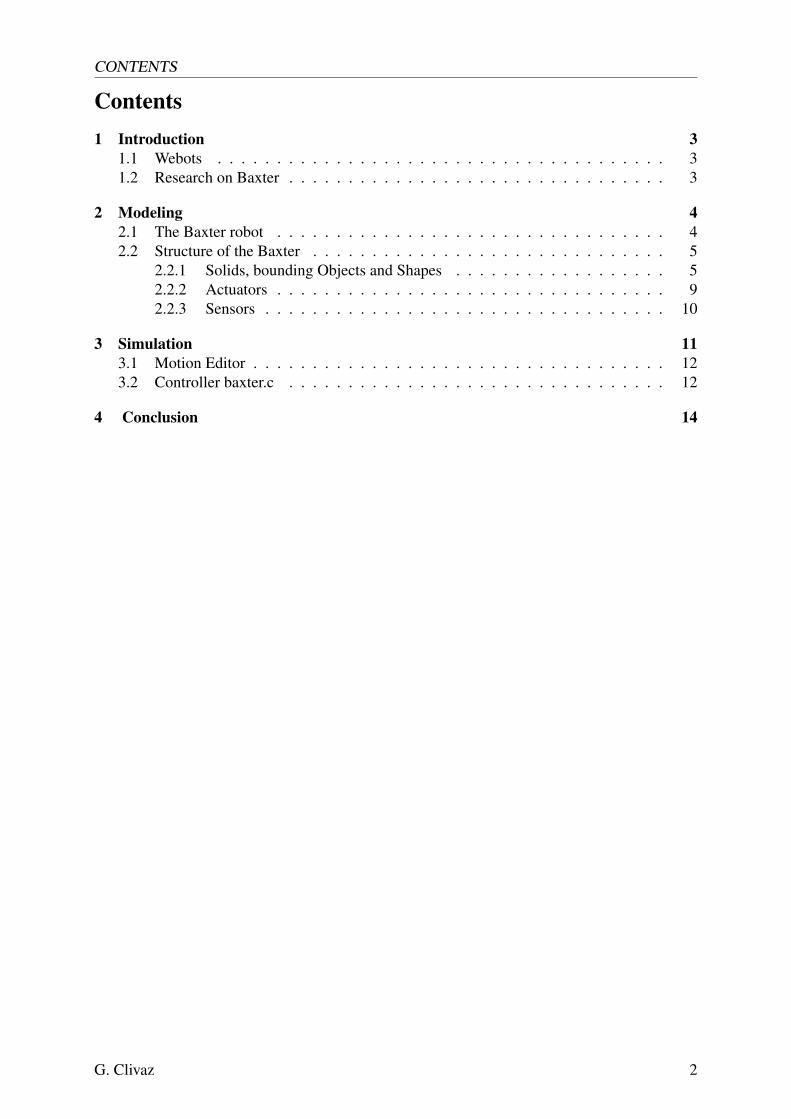
Contents1 Introduction 3
1.1 Webots . . . . . . . . . . . . . . . . . . . . . . . . . . . . . . . . . . . . . . 31.2 Research on Baxter . . . . . . . . . . . . . . . . . . . . . . . . . . . . . . . . 3
2 Modeling 42.1 The Baxter robot . . . . . . . . . . . . . . . . . . . . . . . . . . . . . . . . . 42.2 Structure of the Baxter . . . . . . . . . . . . . . . . . . . . . . . . . . . . . . 5
2.2.1 Solids, bounding Objects and Shapes . . . . . . . . . . . . . . . . . . 52.2.2 Actuators . . . . . . . . . . . . . . . . . . . . . . . . . . . . . . . . . 92.2.3 Sensors . . . . . . . . . . . . . . . . . . . . . . . . . . . . . . . . . . 10
3 Simulation 113.1 Motion Editor . . . . . . . . . . . . . . . . . . . . . . . . . . . . . . . . . . . 123.2 Controller baxter.c . . . . . . . . . . . . . . . . . . . . . . . . . . . . . . . . 12
4 Conclusion 14
G. Clivaz 2

1 INTRODUCTION
1 IntroductionThis project takes part in a semester project with the Cyberbotics company, situated at theSwiss Federal Institute of Technology in Lausanne. The center of interest of this work is therobot called Baxter. This industrial robot is fairly recent, as its creation has been introduce tothe industrial domain since 2012, and its future seems promising. the purpose of this project isthus to collect information on this robot, in order to create a first simulation on the Cyberboticssoftware, Webots.
In this introduction, the report will first present briefly Webots, to get an idea of the softwareand how to familiarize with it. This first part will also introduce the contacts which have helpedus to find informations for this project. Then, through this report, the modeling of the robot willbe seen in details, and finally his simulation in a world by a controller.
1.1 WebotsWebots is a software program managed by the company Cyberbotics, located onthe site of theSwiss Federal Institute of Technology in Lausanne. This software is specially developed tocreate and program simulations of mobile robots in an environment. To learn the the first stepsand get accustomed with Webots, a series of several tutorials are proposed on the website ofCyberbotics. These tutorials are a quite good way to begin with Webots. Indeed, they are wellexplain and especially quite fast, less than 30 minutes for each. As Webots is an rather intuitiveprogram, only the essential needed to begin with Webots is shown in these tutorials. Otherrobots already on Webots can also give a good inspiration to help for programming, like thee-puck, one of the basic and easiest robot to use, already coded on Webots. This especially helpto understand how to program the controller in C.
1.2 Research on BaxterIn parallel with the familiarization of Webots, a search of any informations that could concernthe Baxter was leaded. From the search, two main responses came back. The first was fromRethink Robotics, which is the company that develops this robot. In their answer, we receiveda link containing the URDF file, with all the meshes files attached. The second answer camefrom Generation Robots, with the same informations than the one from Rethink Robotics. Witha script converting URDF files into PROTO, we were able to use most parts of the code theysent us. Concerning the specifications of the Baxter , only the basic informations about sensorsand actuators were given, that are also findable on their website.
G. Clivaz 3

2 MODELING
2 ModelingOnce the Webots initiation and the collect of informations mostly done, the modeling workcould start. This part will first present a short description of the Baxter robot and the innovationswhich comes with this robot to the industrial world. Then, it will detail the robot structure andfeatures, as it is coded on the Webots software.
2.1 The Baxter robotThe Baxter robot has been developed by the company Rethink Robotics, founded by RodneyBrooks. This industrial robot has been created to perform easy tasks, like taking objects andload them in a destined place. The final goal that aim this robot would be to replace humansin industry for these examples of repetitive tasks. With the possibilities of buying this kind ofrobot with a profitability higher than with manoeuvres, the companies would may slowly comeback in our developed country.
As it is shown in the figure 1, the Baxter has two arms, each with seven degrees of freedom,and then an end-effector to seize objects. What make this robot so interesting for a industrialcompany is its ability to learn by itself, and be used by usual worker who does not have a highlevel of knowledge in programming. Indeed, by moving its arm manually, the Baxter is ableto learn and memorize the movement, to repeat it by itself after. Workers just have to trainit during some minutes, without programming. It is designed and equipped with sensors towork without cages, in safety conditions for the humans around, and can adapts to variationsin the environment around him. People from the company will have the time to concentrate onhigher-level tasks, if the Baxter do the easy and repeatable one.[3]
Figure 1: Baxter Robot [1]
G. Clivaz 4

2 MODELING
2.2 Structure of the BaxterAs it is presented below, the modeling has been done mainly by the provided URDF file fromRethink Robotics and Generation Robots at this link :
• https://github.com/RethinkRobotics/baxter common/tree/master/baxter description
The modeling work has then been directly done on a PROTO files, not in the Scene tree sidebar. The script URDFtoPROTO.py, written in python, convert the URDF files into PROTO. Theversion Python 2.7 is needed for this, the 3.4 version did not work. From the command, once inthe repertory of the script, we just needed to write :
python URDFtoPROTO.py baxter.urdf
with the URDF file in argument. The PROTO file is structured as the robot option in Webots,and is detailed below. On the link given, there were also meshes files, which contains all the 3Dshapes.
2.2.1 Solids, bounding Objects and Shapes
The robot structure on Webots is a following of solid parts, named Solids. As a hierarchicaltree, the main solid is taken as a base and other solids extend from this base, called children. Ifother members follow, they becomes children of the last, etc... The Baxter structure begins withthe solid base as a base. From it, there are five main members, built as a string of solids :
• The torso, which is the massive central part of the robot.
• The pedestal that carry the whole robot, with four wheels to move it manually.
• The head, with its screen and camera, and one motorized DoF for the screen rotation.
• The right and left arms, composed as a cascade of solids, each separated from the last byan pivot joint, driven by a rotational motor.
• The right and left grippers, with their linearly motorized clamps.
This hierarchical structure came from the baxter.urdf file. Each solid had already a given mass,as for its inertial matrix, center of mass and density. In baxter.proto, solids with their namefinishing with itb are commented, like right torso itb, right arm itb and similarly for the leftside. These are the interface buttons, called now the navigator. It describe the user input scrollwheel and buttons, including the output LEDs surrounding. As we did not use them for this firstsimulation, the solids are still there, but commented.
To define the limits of a solid, Webots use Bounding Objects, which can have basic form likea capsule or a cylinder, or also a complex form, drawn on a 3D software like Blender or Solid-works. A bounding object in collision with another will be stop by the bounds, except if onesolid is the direct children of the other. the Baxter has basic bounding object for every solids,yet there are two complex bounding object available :
• The solid torso, which can have the baselinkcollision shape, the original shape given inthe meshes files, now as a proto.
• The solid pedestal, this time with the pedestallinkcollision shape.
For a question of simplicity, we did not use these two bounding objects because it could havebeen too heavy computationally for the simulation.
G. Clivaz 5

2 MODELING
Finally, a last important feature of a solid is the Shape children. It represents the visual form,color, material of the object. The conversion from an URDF to a PROTO file did not convert theshapes given in the meshes files, though no errors had been reported by the script. The shapeswere then open in Blender, and registred in WRML file, and then modified as PROTOs. Theproto did not convert the color, so I had to had the line diffuseColor in the PROTO. To make iteasier, the shape had to be split by material in Blender, each material with its own color.
Another weird consequence of the conversion was the non-logical place of the bounding objectand the shapes. For the shape, it could be explain because Blender does not have the samereferential than Webots, so the object should not be moved on Blender before saving in WRML,and the shape needed to be rotated by a Transform around one or more axes. The same was donefor the solids, it needed to be rotated every time to get an arm that looked and moved logically.However, the translation did not have to be corrected, so I think this come only because of adifference of referential with the original software were the baxter has been program.
Figure 2: Complete view of the Baxter robot
List of Solids and corresponding Shape
No Solids corresponding shape (.proto)
0 base —-
1 torso BASE
2 pedestal PEDESTAL
G. Clivaz 6
2 MODELING
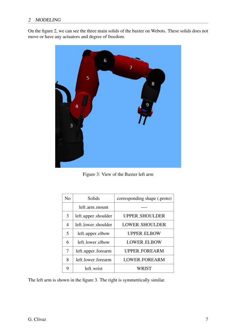
On the figure 2, we can see the three main solids of the baxter on Webots. These solids does notmove or have any actuators and degree of freedom.
Figure 3: View of the Baxter left arm
No Solids corresponding shape (.proto)
left arm mount —-
3 left upper shoulder UPPER SHOULDER
4 left lower shoulder LOWER SHOULDER
5 left upper elbow UPPER ELBOW
6 left lower elbow LOWER ELBOW
7 left upper forearm UPPER FOREARM
8 left lower forearm LOWER FOREARM
9 left wrist WRIST
The left arm is shown in the figure 3. The right is symmetrically similar.
G. Clivaz 7

2 MODELING
Figure 4: View on the gripper
No Solids corresponding shape (.proto)
9 left wrist WRIST
left hand —-
10 left gripper base ELECTRIC GRIPPER
11 left gripper1 F0030517
12 left gripper2 F0030517
The gripper with the end of the wrist is shown in the figure 4. In reality, the finger, or clamps ofthe gripper are interchangeable. The shape of nine different forms of fingers are registered intoPROTO files, but for the simulation, only one kind was used.
Figure 5: View on the head, screen, and sonar ring
G. Clivaz 8

2 MODELING
No Solids corresponding shape (.proto)
13 sonar ring solid Cylinder form
14 base head BASE HEAD
dummyhead1 —-
15 screen SCREEN
The head, screen and sonar solids are indicated in the figure 5. The sonar ring beholds thedevice sensor. The screen hold the display device, indicated with the number 16, and which iscoded in the shape SCREEN.proto. The function of the dummyhead solids is still not known,may this is an actuator.
2.2.2 Actuators
Each arm, from the base to the wrist, has 7 pivot links, which give a total for the arm mobility of7 degrees of freedom. Each degree is driven and controlled by a rotational motor. The gripper,with the couple of pliers, are not included in the 7 degrees of freedom.
Figure 6: Axis for the rotation for the 7 degree of the arms
G. Clivaz 9

2 MODELING
No name of the actuator Max Torque [Nm]
1 left s0 50
2 left s1 50
3 left e0 50
4 left e1 50
5 left w0 15
6 left w1 15
7 left w2 15
The figure 6 indicates the axis of rotation for the seven rotational motor in the arm. Maybebecause of a problem in the conversion URDF to PROTO, the range of the angles were not reallylogical. Some motors could almost not move. I thus have shifted the range, always keeping thesame difference between the max and min. The gripper have both two linear motors, with arange from -0.02 to 0.02 in Webots, with a maximum torque I have let at 15 [Nm]. Finally,the head has one degree of freedom because of its rotational motor head pan, with a maximumtorque non-indicate, and a range over 180°.
2.2.3 Sensors
The Baxter robot has been given many types of sensors like distance sensors, and is alsoequipped with cameras. There are a front camera and a sonar ring around the head, to de-tect human presence, and react to it, for more safety conditions of work. The hands are alsoequipped with cameras. The movement of the robot are thus vision-guided with more precisionthan with only the head camera. Infra-red distance sensors can also be found in the hands.
Cameras The conversion from the URDF to PROTO file did not add exactly the sensors. Allthe sensors are under Solid form, so the sensors specifications come from the datasheets ofRethink Robotics. There are three cameras on the Baxter, one per hand and the last on the headpart. Only one kind of camera specification was found in the documentation, so it is supposedin the simulation that the three cameras are similar. The resolution maximum of the camera is1280x800 pixels.
Infra-red distance sensors These distance sensors are situated in the hands. Their range ofdetection goes from 4 to 40 [cm].
Sonar-ring This sensor is situated almost at the top of the robot. It can detect by ultrasoundany object or human over 360 degree. However, the range of this sensor did not figure in thedata sheet, so in the simulation, the sensor can detect from 0.05 to 50 m, which were the valuesin the baxter.urdf file.
Screen The Baxter also has a screen, which can react to the task given and indicate by manyfacial expression what it does, or if there was a misunderstand in the task given. The screenresolution is 1024 x 600 pixels.
G. Clivaz 10
3 SIMULATION
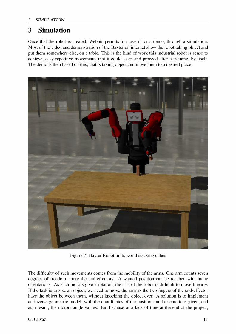
3 SimulationOnce that the robot is created, Webots permits to move it for a demo, through a simulation.Most of the video and demonstration of the Baxter on internet show the robot taking object andput them somewhere else, on a table. This is the kind of work this industrial robot is sense toachieve, easy repetitive movements that it could learn and proceed after a training, by itself.The demo is then based on this, that is taking object and move them to a desired place.
Figure 7: Baxter Robot in its world stacking cubes
The difficulty of such movements comes from the mobility of the arms. One arm counts sevendegrees of freedom, more the end-effectors. A wanted position can be reached with manyorientations. As each motors give a rotation, the arm of the robot is difficult to move linearly.If the task is to size an object, we need to move the arm as the two fingers of the end-effectorhave the object between them, without knocking the object over. A solution is to implementan inverse geometric model, with the coordinates of the positions and orientations given, andas a result, the motors angle values. But because of a lack of time at the end of the project,
G. Clivaz 11

3 SIMULATION
this solution was not used. Instead, the motors angles were found experimentally. To seize theobject, the arm movement was decomposed in two. First the fast move until close from thewanted position, and finally a last move really slow and as linear as possible.
During the simulation, the Baxter was then able to seize rectangular objects, one by the sideand the other from the top, and to stack the second one on the first, without knocking themover. Actually, seizing objects is one of the quality of the Baxter that could be shown duringthe simulation, not as its other main interesting quality. Indeed, in reality, a worker can takemanually the arm of the Baxter, make the move with it, and the Baxter will learn and repeat itindividually, but this was avoided in the simulation because of a lack of time, knowledge on thetopic, and mainly because we directly give the angles to each motors in the controller.
The simulation can be done completely on a controller, coded in a C-file. Webots has alsoanother tool, the Motion Editor, which permit to test and save series of movement.
3.1 Motion EditorThe Motion Editor is a tool used to registered a series of movements of the actuators. The se-quence of new positions of the motors/actuators is then registered in a file.motion, which can bereused on the Motion Editor, or loaded by the controller with the function load motion files()and start motion(WbMotionRef motion). In the case of the Baxter’s demo, the different se-quences used to move the actuators are not loaded from the motion file in the controller, dueto a better speed control with the controller code, as it is explained after. However, the MotionEditor tool was very useful to find the right actuators values for the desired move, easier andfaster than to revert the simulation after having modified and compiled the code.
3.2 Controller baxter.cThis C-file controls every sensors, motors or other tools that could be equipped on the robot.The first function that is called in the main after the initialisation is find and enable device(),so the controller enable all the devices of the Baxter. Once this is done, the movement part ofthe demo begins. The different joints are registered in five different arrays :
• right arm motors and left arm motors , both containing the seven rotational motors ofeach arms.
• right gripper motors and left gripper motors , both containing the two linear motors ofeach hands.
• head pan motor for the rotational motor of the head.
To move one arm by example, an array is created with seven values corresponding to the anglesfor the different motors and the right arm motors take each values one by one in a loop FOR,by the two functions wb motor set position and wb motor set velocity.
Orders can be given from the keyboard during the simulation, once that the keyboard has beenenabled in the code. As long as nothing is entered with the keyboard, a loop WHILE continueto run and check. Once it finds an keyboard input, the code enter in a SWITCH instruction. Asit was explain at before just before, we need sequence of movement with different velocities tonot knock the object over. These are the keyboard main options for the demo :
G. Clivaz 12

3 SIMULATION
• the keyboard key ’i’, to move both arms to their initial position.
• the keyboard key ’r’, to first to move the right arm toward the cube after opening thegripper. Then it takes the cube and close the gripper, to move it somewhere else, open thegripper and goes back first slowly and linearly, and then quickly to the initial position.
• the keyboard key ’l’, to first to move the left arm toward the cube after opening thegripper. Then it takes the cube from the top and close the gripper, to move it over the othercube, already displaced. The gripper opens and the arm goes back, again first slowly andlinearly, and then quickly to the initial position.
The function wb robot step(20 * TIME STEP) is used to make the robot wait a desired time be-tween two other instructions, otherwise the robot directly goes to the second instruction values.More case could be used with the SWITCH, but these are the cases used in the demo.
G. Clivaz 13

REFERENCES
4 ConclusionThis project was mainly a work on the software Webots, so I get used to a part of it, with itsgood features and also difficulties. I personally found Webots quite interesting concerning thesimulation part of the robot in his world. Many robots are already presents, ready to use for asimulation. It was the first simulation software I had used, but I got a good feeling of it. Thecontrol of a robot seems quite realistic, with a wide choice of parameters, sensors, actuators,...to use and do. The controller coded in C is easy to get accustomed to, especially with the helpof examples.
However, I met some difficulties during the modeling of the robot. I lost a considerable timeduring this part of the project because of some problems with PROTO files. By example, whenan error was found in the baxter.proto, Webots could not response and I had to close it, find theerror by myself and save the file, and then I could reopen the world on Webots. I thus thinkthe part of the software concerning the creation of the robot, and the PROTO files could beimproved.
Concerning the project, it has finally in a main part get close of its principal objective, whichwere to create a version of the Baxter robot on Webots. The response and help received fromother companies was really helpful. Even if I met problem coming from the conversion of theURDF file, the main structure of the robot was given.
Now that the robot has been created on Webots, an interesting continuation of the project wouldbe to improve the controller. By example, it would be interesting for the Baxter to detect theobject and take it by visual control. Also, Rethink Robotics and Generation Robots were readyto help from the beginning. Now that a first simulation has been done, they may could be moreinterested and send more informations for further.
References[1] Rethink Robotics. Baxter research robot.
[2] Rethink Robotics. Brochure ”baxter for packaging”.
[3] Rethink Robotics. Baxter arm and hardware specifications v2-3, 2013.
G. Clivaz 14