baumann actuator instructions - hanse envhanseenv.com/phocadownload/act.1.im.77.pdf · 3...
TRANSCRIPT

Instruction ManualACT_IMD103352X012October 2008 Pneumatic Actuators
springs. The use of mul ti ple springs also of fers a sub stan tial ly low er pro fi le. The units in clude zinc-plated, epoxy-coat ed steel di a phragm cas es and, except for the type 16, an ep oxy-coat ed ductile-iron yoke. All re main ing metal parts are made of ei ther stain less or zinc plat ed steel for op ti mum cor ro sion resistance. All actuators are suitable for a stan dard am bi ent temperature range of -20°F to 160°F (-29oC to 71oC); for higher tem per a ture service, an optional design is available, consult the factory.
SCOPE OF MANUALThis instruction manual includes installation, maintenance, and parts information for the Baumann pneumatic actuators.
No person may install, operate or maintain a Baumann actuator without fi rst being trained and qualifi ed in valve, actuator and accessory installation, operation and maintenance, and carefully reading and understanding the contents of this manual. If you have any questions about these instructions, contact your Fisher sales offi ce before proceeding.
DESIGN NOTESThe same basic actuator may be con fi g ured in sev er al ways. Variations may produce ei ther a 5/16 in (7.9 mm),1/2 in (12.7 mm), or 3/4 in (19.1 mm) stroke. The Spring Tables list the nom i nal bench spring rang es. Each line in the table lists the high and low limits for the signal air pres sure, mea sured in pounds per square inch (psi) and bar. These sig nal pres sures pro duce the rated stroke lengths when the actuator is not load ed. The sig nal air con nec tions use 1/4 (6.4 mm) NPT fi t tings, and are lo cat ed in both the low er (43) and upper (44) di a phragm cas es. Use the lower con nec tion for an “Air-to-Re tract” (ATR) ac tu a tor and the up per con nec tion for an “Air-to-Ex tend” (ATE) ac tu a tor. The sig nal air pres sure should not exceed 35 psi (2.4 bar). High er pres sures may cause the di a phragm to leak.
Baumann™ Actuator Instructions(English - Metric Version)
INTRODUCTIONThe Baumann™ multiple-spring diaphragm ac tu a tors are pow er ful and compact devices designed to op er ate con trol valves, louvers, dampers or me chan i cal speed ad just ing devices. The actuators can pro vide either di rect air-to-ex tend ac tion (ATE) or re verse air-to-retract ac tion (ATR). When an ATE ac tu a tor is installed on a typical Baumann valve, it pro vides an air-to-close (ATC) or fail-open func tion. When an ATR ac tu a tor is installed, it pro vides an air-to-open (ATO) or fail-closed func tion. The de sign fea tures ex cep tion al ly low hys ter e sis due to the ab sence of side loads im posed by mis align ment of single coiled
CONTENTS
Introduction ..................................................................1Scope of Manual ..........................................................1Design Notes ...............................................................1Safety Precautions .....................................................2Attaching an Air-to-Retract (ATR) Actuator to a Valve - Part 1 ..............................................................3Bench Range Adjustment - Air-to-Retract (ATR) Actuator ...........................................................3Attaching an Air-to-Retract (ATR) Actuator to a Valve - Part 2 ..............................................................4Attaching an Air-to-Extend (ATE) Actuator to a Valve - Part 1 ............................................................. 4Bench Range Adjustment - Air-to-Extend (ATE) Actuator ...........................................................4Attaching an Air-to-Extend (ATE) Actuator to a Valve - Part 2 ............................................................. 5Spring Replacement, Changing Bench Range ........ 5Field Conversion - ATE to ATR or ATR to ATE ......... 5Removing the Actuator from the Valve ..................... 6Disassembling the Actuator .......................................6Reassembling the Actuator - ATE Type .................... 7Reassembling the Actuator - ATR Type ....................7Actuator Maintenance ................................................ 8Handwheel Operation .................................................8Parts Lists ...............................................................9-21Dimensions ................................................................22

2
Instruction ManualACT_IM
October 2008Pneumatic Actuators
WARNING
Always wear protective gloves, clothing, and eye wear when performing any installation operations to avoid personal injury.
Personal injury or equipment damage caused by sudden release of pressure or bursting of pressure retaining parts might result if service conditions exceed those for which the product was intended. To avoid injury or damage, provide relief valve for over pressure protection as required by government or accepted industry codes and good engineering practices.
Personal injury or equipment damage caused by sudden release of pressure or bursting of parts may result if the valve assembly is installed where service conditions could exceed the limits given in the product literature, the limits on the appropriate nameplates, or the mating pipe fl ange rating. Use pressure-relieving devices as required by government or accepted industry codes and good en gi neer ing practices. If you cannot determine the ratings and limits for this product, contact your Baumann offi ce or sales representative before proceeding.
Personal injury could result from packing leakage. The packing might require some readjustment to meet specifi c service conditions.
WARNING
WARNING
If you move or work on an actuator installed on a valve with loading pressure applied, keep your hands and tools away from the stem travel path to avoid personal injury. Be especially careful when removing the stem connector to release all loading on the actuator stem whether it be from air pressure on the diaphragm or compression in the actuator springs.
Likewise take similar care when adjusting or removing any optional travel stop. Refer to the relevant actuator Maintenance Instructions.
Often, these types of actuators are at tached to valves which include a stainless steel stem and valve seat. When assembling or ad just ing the actuators, never turn the valve stem when the plug is touching the valve seat . If the two stain less steel parts rotate while they are touching, they can be dam aged very eas i ly.When adjusting the valve stem (5), do not grip the stem directly with pliers or a wrench. This will damage the surface of the stem, and cause dam age to the pack ing in the valve. Instead, counter-tight en the two lock nuts (27) on the stem to geth er. This will al low you to turn the stem by turning the lock nuts with a wrench.
CAUTION
NOTE
Neither Emerson™, Emerson Process Management, Fisher®, nor any of their affi liated entities assumes responsibility for the selection, use, and maintenance of any product. Responsibility for the selection, use, and maintenance of any product remains with the purchaser and end-user.
Check with your process or safety engineer for any additional measures that must be taken to protect against process media.
If installing into an existing application, also refer to the WARNING at the beginning of the Maintenance section in this instruction manual.
3
Instruction ManualACT_IMOctober 2008 Pneumatic Actuators
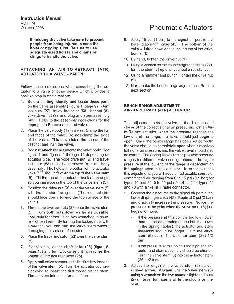
ATTACHING AN AIR-TO-RETRACT (ATR) ACTUATOR TO A VALVE - PART 1
Follow these instructions when assembling the ac- tu a tor to a valve or other device which provides a pos i tive stop in one di rec tion:1. Before starting, identify and locate these parts
on the valve assembly (Figure 1, page 9): stem lock nuts (27), trav el in di ca tor (58), bon net (8), yoke drive nut (9), and plug and stem assembly (4/5). Refer to the as sem bly in struc tions for the appropriate Bau mann con trol valve.
2. Place the valve body (1) in a vise. Clamp the fl at end faces of the valve. Do not clamp the sides of the valve. This may dis tort the shape of the cast ing, and ruin the valve.
3. Begin to attach the actuator to the valve body. See fi gure 1 and fi gures 2 through 14 depending on actuator type. The yoke drive nut (9) and travel in di ca tor (58) must be re moved from the body assembly. The hole at the bot tom of the actuator yoke (17) should fi t over the top of the valve stem (5). Tilt the top of the ac tu a tor back at an an gle so you can ac cess the top of the valve stem (5).
4. Position the drive nut (9) over the valve stem (5) with the fl at side facing up. (The rounded side should face down, toward the top surface of the yoke.)
5. Thread the two locknuts (27) onto the valve stem (5). Turn both nuts down as far as pos si ble. Lock nuts together using two wrenches to coun-ter-tight en them. By turn ing the locked nuts with a wrench, you can turn the valve stem without dam ag ing the sur face of the stem.
6. Place the travel indicator (58) over the valve stem (5).
7. If applicable, loosen shaft collar (25) (fi gure 6, page 13) and turn clock wise until it reaches the bottom of the ac tu a tor stem (26).
8. Apply anti-seize compound to the fi rst few threads of the valve stem (5). Turn the ac tu a tor coun ter -clock wise to locate the fi rst thread on the stem. Thread stem into actuator a half turn.
9. Apply 15 psi (1 bar) to the signal air port in the low er diaphragm case (43). The bottom of the yoke will drop down and touch the top of the valve bon net (8).
10. By hand, tighten the drive nut (9).11. Using a wrench on the counter-tight ened nuts (27),
turn the stem (5) up until you feel a re sis tance.12. Using a hammer and punch, tighten the drive nut
(9). 13. Next, make the bench range ad just ment. See the
next section.
BENCH RANGE ADJUSTMENT AIR-TO-RETRACT (ATR) ACTUATOR
This adjustment sets the valve so that it opens and clos es at the correct signal air pressures. On an Air-to-Retract ac tu a tor, when the pressure reaches the low end of the range, the valve should just begin to open. Once the bench range has been set cor rect ly, the valve should be completely open when it receives full sig nal air pres sure, and the valve travel should also be cor rect. The Spring Tables list the pos si ble pres sure rang es for different valve con fi g u ra tions. The sig nal pressure at the low end of the range is de pen dent on the springs used in the ac tu a tor. In or der to make this ad just ment, you will need an ad just able source of com pressed air rang ing from 0 to 15 psi (0-1 bar) for types 16 and 32, 0 to 20 psi ( 0-1.4 bar) for types 54 and 70 with a 1/4 NPT male con nec tor.1. Connect the air source to the signal air port in the
lower diaphragm case (43). Begin at 0 psi (0 bar) and grad u al ly in crease the pressure. No tice the pres sure at the point when the valve stem (5) just be gins to move.• If the pressure at this point is too low (low er
than the recommended bench initials shown in the Spring Tables), the ac tu a tor and stem as sem bly should be long er. Turn the valve stem (5) out of the ac tu a tor stem (26) 1/2 turn.
• If the pressure at this point is too high, the ac- tu a tor and stem as sem bly should be short er. Turn the valve stem (5) into the ac tu a tor stem (26) 1/2 turn.
2. Adjust the length of the valve stem (5) as de- scribed above. Always turn the valve stem (5) using a wrench on the two counter-tightened nuts (27). Nev er turn stems while the plug is on the seat.
If hoisting the valve take care to prevent people from being injured in case the hoist or rigging slips. Be sure to use adequate sized hoists and chains or slings to handle the valve.

4
Instruction ManualACT_IM
October 2008Pneumatic Actuators
ATTACHING AN AIR-TO-RETRACT (ATR) ACTUATOR TO A VALVE - PART 2
1. Once the bench range has been ad just ed cor rect ly, you can complete the as sem bly. Ap ply 15 psi (1 bar) to the signal port on the ac tu a tor.
2. Using two wrenches, unlock the two counter-tight ened nuts (27). There are fl ats on the ac tu a tor stem (26). Hold these fl ats with a wrench and, one at a time, turn each nut up as far as pos si ble. Counter-tighten the two nuts to geth er again.
3. Reduce the air pressure to 0 psi (0 bar). Loos en the screws (57) which hold the travel indicator scale (56) in place. Set the scale so the low est line match es the lev el of the travel in di ca tor wash er.
4. Set the air pressure to the high end of the valve’s op er at ing pressure. The trav el in di ca tor should move through the full rated trav el of 5/16 in, 1/2 in, or 3/4 in (7.9 mm, 12.7 mm, or 19.1 mm).
Note: Shaft collar (25), if applicable, can be set at in ter me di ate positions to provide a minimum open ing valve travel stop following cal i bra tion.
ATTACHING AN AIR-TO-EXTEND (ATE) AC TU A TOR TO A VALVE - PART 1
Follow these instructions when assembling the ac- tu a tor to a valve or another device which provides a pos i tive stop in one direction. (Type 70 is ATR only) 1. Before starting, identify and locate these parts
on the valve assembly, fi gure 1, page 9: stem lock nuts (27), trav el in di ca tor (58), bon net (8), yoke drive nut (9), and plug and stem assembly (4/5). Refer to the as sem bly in struc tions for the appropriate Bau mann con trol valve.
CAUTIONRemember that the valve stem (5) can not be al lowed to turn against the valve seat when the two parts are touching. Before you make any ad just ment, apply 15 psi (1 bar) to the ac tu a tor. This will lift the valve stem away from the seat, and pre vent any chance of dam age.
3. You may have to repeat steps 1 and 2 several times to get the correct setting.
2. Place the valve body (1) in a vise. Clamp the fl at end faces of the valve. Do not clamp the sides of the valve. This may dis tort the shape of the cast ing, and ruin the valve.
3. Begin to attach the actuator to the valve body. The yoke drive nut (9) and travel indicator (58) must be re moved from the body assembly. The hole at the bot tom of the actuator yoke (17) should fi t over the top of the valve stem (5). Tilt the top of the ac tu a tor back at an an gle so you can ac cess the top of the valve stem (5).
4. Position the drive nut (9) over the valve stem (5) with the fl at side facing up. (The rounded side should face down, toward the top surface of the yoke.)
5. Thread the two locknuts (27) onto the valve stem (5). Turn both nuts down as far as pos si ble. Lock nuts together using two wrenches to counter-tight en them. By turn ing the locked nuts with a wrench, you can turn the valve stem without dam ag ing the sur face of the stem.
6. Place the travel indicator (58) over the valve stem (5).
7. If applicable, loosen shaft collar (25) (fi gure 6, page 13) and turn clock wise until it reaches the bottom of the ac tu a tor stem (26).
8. Apply anti-seize compound to the fi rst few threads of the valve stem (5). Place actuator over top of valve bonnet (8). Yoke of actuator will make contact with top of bonnet (8). Extend valve stem (5) into actuator stem (26). Turn stem (5) until it comes to a stop, then back off 1/2 turn.
9. By hand, tighten the drive nut (9).10. Using a wrench on the counter-tight ened nuts (27),
turn the stem (5) up until you feel a resistance.11. Using a hammer and punch, tighten the drive nut (9). 12. Next, make the bench range ad just ment. See the
next section.
BENCH RANGE ADJUSTMENT AIR-TO-EXTEND (ATE) ACTUATOR
This adjustment sets the valve so that it opens and clos es at the correct signal air pressures. On an Air-to-Extend actuator, when the pressure reach es the high end of the range, the valve should be com plete ly closed. Once the bench range has been set cor rect ly, the valve should be com plete ly open when it receives

5
Instruction ManualACT_IMOctober 2008 Pneumatic Actuatorsthe low reading for the sig nal air pressure, and the valve travel should also be cor rect. The Spring Tables list the pos si ble pressure rang es for dif fer ent valve con fi g u ra tions. The sig nal pressure at the high end of the range is de pen dent on the springs used in the ac tu a tor. In or der to make this ad just ment, you will need an ad just able source of com pressed air rang ing from 0 to 15 psi (0-1 bar) for types 16 and 32, 0 to 20 psi ( 0-1.4 bar) for types 54 and 70 with a 1/4 NPT male con nec tor.1. Connect the air source to the sig nal air port in the
up per diaphragm case (44). Gradually in crease the pres sure to ward the high rating list ed in ap- pro pri ate Spring Ta ble. No tice the pres sure at the point when the valve is fully seat ed, and the valve stem (5) stops mov ing.• If the pressure at this point is too high, the
ac tu a tor and stem as sem bly should be long er. Turn the valve stem (5) out of the ac tu a tor stem (26) 1/2 turn.
• If the pressure at this point is too low, the ac- tu a tor and stem as sem bly should be short er. Turn the valve stem (5) into the ac tu a tor stem (26) 1/2 turn.
2. Adjust the length of the valve stem (5) as de scribed in the last step. Always turn the valve stem (5) using a wrench on the two counter-tight ened nuts (27).
CAUTIONRemember that the valve stem (5) cannot be al lowed to turn against the valve seat when the two parts are touching. Before you make any ad just ment, be certain that there is no air sig nal to the actuator.
3. You may have to repeat steps 1 and 2 several times to get the correct setting.
ATTACHING AN AIR-TO-EXTEND (ATE) ACTUATOR TO A VALVE - PART 2
1. Once the bench range has been ad just ed cor- rect ly, you can complete the as sem bly. Apply 0 psi (0 bar) to the signal port on the actuator.
2. Using two wrenches, unlock the two counter-tight ened nuts (27). There are fl ats on the ac tu a tor stem (26). Hold the fl ats with a wrench and, one at a time, turn each nut up until you feel a re sis tance. Counter-tighten the two nuts to geth er again.
SPRING REPLACEMENT, CHANG ING BENCH RANGE
The springs inside the actuator can be re placed or changed if necessary. This is nec es sary if you want to change the “bench range” - the range of pres sures over which the ac tu a tor is de signed to op er ate. The Spring Tables list the pos si ble spring com bi na tions. To use the tables, iden ti fy the stroke and the pres sure range for the new valve confi guration. This will tell you the part num ber and the quan ti ty of the springs need ed.Figures 2 and 3 for type 16, fi gures 4 and 5 for type 32, fi gures 10 and 11 for type 54, and fi gure 14 for type 70 show the cor rect as sem bly confi gurations for Air-to-Ex tend and Air-to-Re tract valves. No tice that both types in clude the same parts, but they are ar- ranged dif fer ent ly. The fol low ing sec tions de tail the dis as sem bly and as sem bly in struc tions.
FIELD CONVERSION - ATE TO ATR OR ATR TO ATE
Except for the type 70, these actuators can be changed in the fi eld from “Air-to-Ex tend” (ATE) op er a tion to “Air-to-Retract” operation, or from ATR to ATE op er a tion. If you are making this change without changing the bench range, you can reuse the same parts. The parts are simply assembled in a different way. This is de scribed in more detail in the following sec tions. The fol low ing sec tions list the dis as sem bly and re as sem bly in struc tions.
Notes: Type 70 is available in ATR only. Field Conversion can not be done on Dual-
Stop Actuators.
3. Apply 15 psi (1 bar) to the signal port. Loos en the screws (57) which hold the trav el in di ca tor scale (56) in place. Set the scale so the lowest line match es the level of the trav el indicator (58).
4. Apply 0 psi (0 bar). The travel indicator (58) should move through the full rated travel of 5/16, 1/2, or 3/4 inches (7.9, 12.7, or 19.1 mm).

6
Instruction ManualACT_IM
October 2008Pneumatic Actuators
REMOVING THE ACTUATOR FROM THE VALVE
1. For an Air-To-Retract (ATR) Actuator Apply 15 psi (1 bar) for type 16 and 32, 20 psi
(1.4 bar) for type 54 and 70, to the sig nal air inlet lo cat ed in the low er di a phragm case (43). This will lift the plug and stem (4/5) away from the valve seat.
For an Air-to-Extend (ATE) Actuator Disconnect the signal air line connected to the
up per diaphragm case (44). This will assure that the ac tu a tor is vented and that the valve plug and stem (4/5) are fully lifted away from the valve seat.
WARNING
To avoid personal injury or property damage by uncontrolled movement of the actuator yoke, loosen the body/yoke nuts or bonnet/yoke nuts by following the instructions in the next step. Do not remove a stuck actuator by pulling on it with equipment that can stretch or store energy in any other manner. The sudden release of stored energy can cause uncontrolled movement of the actuator yoke.
To avoid personal injury or property damage due to actuator springs being under compression, remove the long cap screws last.
The upper actuator casing may remain fi xed to the diaphragm and lower casing during disassembly, even if the casing cap screw have been loosened. If this happens, the actuator springs are still under compression. The upper casing could suddenly come loose and jump, due to the compressed energy of the springs. If the upper casing is stuck to the diaphragm and lower casing when you begin loosening the casing cap screws, pry the casings apart with a prying tool. Always be sure that the springs are dispersing energy and the upper casing is moving against the long bolts during disassembly.
2. For both types Place a wrench on the fl ats of the ac tu a tor stem.
With an additional wrench, en gage the upper locknut (27) on the stem and back out the stem about 1/4" (6.4 mm). (This pro ce dure will pre vent the actuator stem from turn ing and caus ing dam age to the diaphragm).
3. Loosen the yoke drive nut (9). 4. Using the wrench to work against one of the
counter-tightened nuts, turn the valve stem (5) completely down until the end unthreads from the actuator stem (26).
5. Remove the travel indicator (58) from the valve stem (5). Loosen the locknuts (27) and re move them. Re move the yoke drive nut (9).
6. Lift the actuator assembly off of the valve bon net (8).
DISASSEMBLING THE ACTUATOR
1. Remove the actuator from the valve as de scribed earlier.
2. Remove the cap screws (45) and nuts (46). Loos en the nuts from the cap screws grad u al ly and evenly. Some units may have a com bi na tion of longer and shorter screws. After removing the shorter screws, the re main ing longer screws must be loosened evenly. The springs put a lot of force on the di a phragm cases (43/44). It is im por tant to re lease the spring tension grad u al ly be fore you try to open them.
3. Remove the upper diaphragm case (44) and note the position of the parts inside. For the type 70 the upper diaphragm plate (40) must also be re moved.
4. Except for the type 16, lift out the actuator stem (26) with the di a phragm plate (40) and the di a -phragm (39). For the type 16, loos en locknut (30) remove stem (26) through the bot tom.
5. For type 32, 54, and 70 the lower part of the ac tu a tor stem (26) has fl ats. Use these fl ats to clamp the low er end of the stem into a vise. Un screw the Nyloc® nut (30). On an ATE unit, re move the wash er (112)(Key 116 for the 54 actuator), di a phragm (39), di a phragm plate (40), and for the 32 actuator, stop cup (79). NOTE: There is not a stop cup for the type 16 actuator. (An ATR unit has the same parts, but they are attached in a dif fer ent or der.)

7
Instruction ManualACT_IMOctober 2008 Pneumatic Actuators6. Replace the diaphragm (39) and the o-ring(s) (50)
if these parts are damaged.
REASSEMBLING THE ACTUATOR - ATE TYPE
1. Use the fl ats on the actuator stem (26) to grip the lower end of the stem in a vise.
2. For the 32 actuator, place the stop cup (79) in position on the up per end of the stem. On an ATE ac tu a tor, the stop cup faces down.
3. Place the diaphragm plate (40) on the up per end of the stem (26), also facing down.
4. Place the diaphragm (39) in position. The curved part of the diaphragm should open down ward.
5. Place the washer (112)(Key 116 for the 54 actuator) over the open ing in the diaphragm plate.
6. Thread the Nyloc® nut (30) onto the end of the stem (26) and tighten it.
7. Turn the assembly upside-down, and grip the Nyloc® nut (30) in the vise.
8. Place the springs (22) on the diaphragm plate (40). Each spring should be centered on one of the raised “bosses” on the plate.
9. Slide the stop collar (115) over the free end of the actuator stem (26).
10. Check to see that the o-ring (50) is in po si tion on the actuator stem (26).
11. Apply some light grease to the o-ring (50) and to the surface of the actuator stem (26).
12. Slide the lower diaphragm case (43), with the ac-tuator yoke (17) attached, over the ac tu a tor stem (26). Make sure that the outer bolt holes of the low er di a phragm case (43) line up with the holes in the diaphragm (39). If there is in ter fer ence with any of the springs, ro tate the case into an oth er po si tion.
13. Remove the assembly from the vise. Press in on the diaphragm assembly a bit to com press the springs. Flip over the assembly and re at tach the upper di a phragm case (44). As you do this, be sure that all of the springs are up right, and none of them are sitting on one of the bolt heads. Insert the cap screws (45) and tight en the nuts (46). It may be necessary to com press the springs slight ly to start the nuts. Tight en the nuts evenly, and cross from one side of the as sem bly to the other as you tight en. This will guar an tee that the spring ten sion is tak en up even ly.
14. Apply air pressure to the actuator and check for fric tion or leakage. The ac tu a tor should trav el smoothly through the entire travel range. Ap ply leak detection fl uid to the area around the guide bush ing (54). Also check for leaks around the outer edge of the di a phragm (39).
15. Make the adjustments described in the sec tion on “Bench Range Ad just ment - Air-to-Ex tend (ATE) Valve.”
REASSEMBLING THE ACTUATOR - ATR TYPE
1. Use the fl ats on the actuator stem (26) to grip this part in a vise.
2. Place the washer (112)(Key 116 for the 54 actua-tor) over the thread ed part of the actuator stem (26).
3. Place the diaphragm (39) in position. The curved part of the diaphragm should open up ward.
4. Place the diaphragm plate (40) on the upper end of the stem (26), also facing up.
5. For the 32 actuator, place the stop cup (79) in position on the up per end of the stem (26). On an ATR ac tu a tor, the stop cup fac es up.
6. Thread the Nyloc® nut (30) onto the end of the stem (26) and tighten it.
7. Slide the stop collar (115) over the free end of the ac tu a tor stem (26).
8. Check to see that the o-ring (50) is in position on the ac tu a tor stem (26).
9. Apply some light grease to the o-ring (50), and to the sur face of the actuator stem (26).
10. Slide the actuator stem into the lower di a phragm case (43). Turn the as sem bly so the holes in the di a phragm (39) line up with the holes in the di a phragm case (43).
11. Place the springs (22) on the diaphragm plate (40). Each spring should be centered on one of the raised “boss es” on the plate.
12. Reattach the upper diaphragm case (44). As you do this, be sure that each of the springs is up right. Insert the cap screws (45) and tight en the nuts (46). It may be nec es sary to press down on the upper diaphragm case (44) a bit to com press the springs slightly and start the nuts. Tight en the nuts evenly, and cross from one side of the assembly to the oth er as you tighten. This will guar an tee that the spring ten sion is taken up even ly.
8
Instruction ManualACT_IM
October 2008Pneumatic Actuators
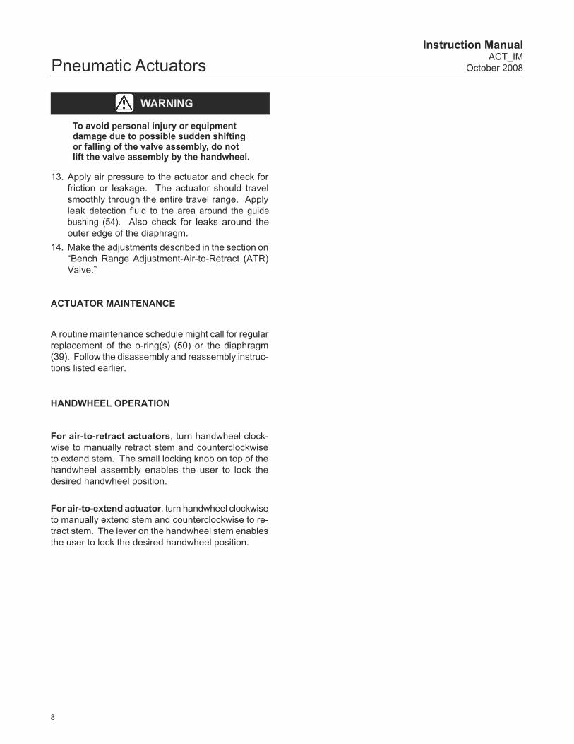
WARNING
To avoid personal injury or equipment damage due to possible sudden shifting or falling of the valve assembly, do not lift the valve assembly by the handwheel.
13. Apply air pressure to the actuator and check for fric tion or leakage. The ac tu a tor should trav el smooth ly through the entire travel range. Apply leak de tec tion fl uid to the area around the guide bush ing (54). Also check for leaks around the out er edge of the diaphragm.
14. Make the adjustments described in the sec tion on “Bench Range Ad just ment-Air-to-Re tract (ATR) Valve.”
ACTUATOR MAINTENANCE
A routine maintenance schedule might call for reg u lar re place ment of the o-ring(s) (50) or the di a phragm (39). Follow the dis as sem bly and re as sem bly in struc -tions listed earlier.
HANDWHEEL OPERATION
For air-to-retract actuators, turn handwheel clock-wise to manually retract stem and counterclockwise to extend stem. The small locking knob on top of the handwheel assembly enables the user to lock the desired handwheel position.
For air-to-extend actuator, turn handwheel clockwise to manually extend stem and counterclockwise to re-tract stem. The lever on the handwheel stem enables the user to lock the desired handwheel position.

9
Instruction ManualACT_IMOctober 2008 Pneumatic Actuators
Figure 1. Typical Valve Components
Table 1. COMMON VALVE PARTS
KEY NO. DESCRIPTION
1 Body
2 Seat Ring
4 Plug
5 Stem
8 Bonnet
8A Bonnet Bushing
9 Drive Nut
10 Packing Follower
12 O-Ring
14 Packing
27 Locknuts
49 Body Gasket
58 Travel Indicator
EB0010

10
Instruction ManualACT_IM
October 2008Pneumatic Actuators
Figure 2. Type 16 Actuator, Air-to-Retract (ATR) Figure 3. Type 16 Actuator, Air-to-Extend (ATE)
Table 2. TYPE 16 ACTUATOR COMMON PARTS
Table 3. TYPE 16 ACTUATOR SPRING RANGES
EB0121 EB0122
KEY NO. DESCRIPTION PART NUMBER QTY17 Actuator yoke 81811 122* Spring See Table 3 See Table 326 Actuator Stem 81840 130 Nut, Self-Locking 81844 139* Diaphragm 011759-001-686 140 Diaphragm Plate 81850-1 143 Diaphragm Case, Lower 81820 144 Diaphragm Case, Upper 81823 145 Hex Head Cap Screw 81824 846 Nut, Hex 81825 850* O-Ring (FKM (Fluorocarbon)) 24080 254 Coupling 81830 1
56Travel Scale, 0.5 inch 983674-001-250
1Travel Scale, 0.3125 87935
57 Screw 81812 262 Serial Plate 81891 1112 Washer 25861-24 1113 Vent Plug 24147 1115 Collar 81870 1116 Collar (0.3125 inch travel only) 81842 1119 Drive Screw 24686 2
*Recommended Spare Parts
ACTIONTRAVEL NOMINAL BENCH
SPRING RANGESPRING
PART NO.(KEY 22)
QTY COLLAR(KEY 116) QTY
in mm psi bar
ATE(ATC)
0.5 12.7 3-13 0.2-0.9 81860 4 --- ---
0.3125 7.9 4-13 0.3-0.9 81864 4 81842 1
ATR(ATO)
0.5 12.7 3-15 0.2-1.0 81860 5 --- ---
0.3125 7.9 4-15 0.3-1.0 81863 4 81842 1

11
Instruction ManualACT_IMOctober 2008 Pneumatic Actuators
Figure 4. Type 32 Actuator, Air-to-Retract (ATR)
Figure 5. Type 32 Actuator, Air-to-Extend (ATE)
EB0123
EB0124

12
Instruction ManualACT_IM
October 2008Pneumatic Actuators
Table 4. TYPE 32 ACTUATOR COMMON PARTS
KEY NO. DESCRIPTIONTYPE 32 ACTUATOR
0.5 in TRAVEL (12.7 mm) 0.75 in TRAVEL (19.1 mm)PART NO. QTY PART NO. QTY
17/54Yoke w / guide bushing 24184-10
124184-10
1Yoke (for Fisher® valves) w / guide bushing 24184-1-1 24184-1-1
19 Gasket (standard) 009191-445-883
1009191-445-883
1Gasket (Hi-Temperature) 009191-445-885 009191-445-885
22 Actuator Spring See Table 5 --- See Table 5 ---
26Actuator Stem, 5/16 thread 24613
124613
1Actuator Stem (for Fisher valves), 3/8 thread 24613-2 24613-2
30 (B) Nut, Nyloc See Key No. 39A
39 (B) Diaphragm See Key No. 39A
39A (A)(B)Diaphragm Kit (standard) 24462 1 24462 1
Diaphragm Kit (Hi-Temperature) 24464 1 24464 1
40 Diaphragm Plate 24811 1 24811 1
43 Diaphragm Case (Lower) 011767-004-999 1 011767-004-999 1
44 Diaphragm Case (Upper) 011766-001-999 1 011766-001-999 1
45 Cap Screw 25913-1 8 25913-1 8
46 Nut 971511-011-250 8 971511-011-250 8
50 (B) O-Ring (FKM (Fluorocarbon)) See Key No. 39A
56 Travel Indicator Scale 983674-001-250 1 983674-003-250 1
57 Machine Screw 971302-003-250 2 971302-003-250 2
62 Serial Plate 983753-001-600 1 983753-001-600 1
64 Cap Screw 971000-007-1 6 971000-007-1 6
79 Stop Cup See Table 5 --- See Table 5 ---
112 Washer 25861-24 1 25861-24 1
113 Vent Plug 24147 1 24147 1
115 Stop Collar 24187 1 24187 1
119 Drive Screw 24686 2 24686 2
NOTES: A. Recommended Spare Parts B. Diaphragm Kit (39A) includes Locknut (30), O-Ring (50), and Diaphragm (39). These parts are not sold separately.
ACTIONTRAVEL NOMINAL BENCH
SPRING RANGE SPRING PART NO.(KEY 22)
QTY STOP CUP(KEY 79) QTY
in mm psi bar
ATE(ATC)
0.5 12.7
3-9 0.2-0.6 24820 4 24116 1
3-10 0.2-0.7 24821 6 24116 1
3-13 0.2-0.9 24820 6 24116 1
0.75 19.13-10 0.2-0.7 24821 4 24830 1
3-13 0.2-0.9 24821 6 24830 1
ATR(ATO)
0.5 12.7
3-9 0.2-0.7 24820 4 24116 1
5-15 0.3-1.0 24820 6 24116 1
7-15 0.5-1.0 24821 6 24830-1 1
0.75 19.13-9 0.2-0.7 24821 4 24830 1
5-15 0.3-1.0 24827 6 24830 1
Table 5. TYPE 32 ACTUATOR SPRING RANGES

13
Instruction ManualACT_IMOctober 2008 Pneumatic Actuators
Figure 6. Type 32 Actuator with Handwheel and Optional Dual Stop, Air-to-Retract, (ATR)
Table 6. TYPE 32 ATR WITH HANDWHEEL AND DUAL STOP
EB0125
Do not continue to turn handwheel after the stem is fully extended (valve fully closed and plug seated) or fully retracted (valve fully open) to avoid damage to the handwheel assembly.
KEY NO. DESCRIPTION PART NO. QTY
25 Shaft Collar (optional) 24732-2 1
26
Actuator Stem, 5/16 thread 24613-4 1
Actuator Stem (for Fisher® valves), 3/8 thread 24613-3 1
Actuator Stem (for optional dual stop collar) 24613-16 1
39A (A)(B)Diaphragm Kit (standard) 24462-2 1
Diaphragm Kit (Hi-Temperature) 24464-2 1
40 Diaphragm Plate 24811-1 1
44 Diaphragm Case (Upper) 011766-012-999 1
49 Spacer 24726 1
81 Spacer 24855-1 1
82 Spacer 24855 1
83 Nut 24602-1 1
84 Clevis 24603-1 1
85 Nut, Round Bronze 24604 1
87 Screw, Set Socket 24606 2
88 Washer, Flat 24620 1
89 Screw, Socket Head 24619 1
90 Handwheel 24605 1
91 Washer, Flat 25958 1
93 Locking Knob 24607 1
NOTES: A. Recommended Spare Parts B. Diaphragm Kit (39A) includes O-Ring (50) and Diaphragm (39). These parts are not sold separately.
CAUTION

14
Instruction ManualACT_IM
October 2008Pneumatic Actuators
Table 7. TYPE 32 ATE WITH HANDWHEEL AND DUAL STOPKEY NO. DESCRIPTION PART NO. QTY
26Actuator Stem, 5/16 thread 24613-4
1Actuator Stem (for Fisher® valves), 3/8 thread 24613-2
44 Diaphragm Case (Upper) 011766-012-999 1
52 Handwheel, P/N 25977
Kit Part No. 25985 1 53 Roll Pin, P/N 25897
55 Stem, Handwheel, P/N 25976
58 Nut, Self-Locking 25924 1
59 Adapter, Handwheel 25978-2 1
60 O-Ring 25926 1
61 Lock-Nut 25979 1
63 Spring Pin 24835 1
82 Bushing, Handwheel 24834 1
126Hex Bolt (0.5 in travel) 24756-6
2Hex Bolt (0.75 in travel) 24756-7
127 Hex Nut 971511-010-250 2
Do not continue to turn handwheel after the stem is fully extended (valve fully closed and plug seated) or fully retracted (valve fully open) to avoid damage to the handwheel assembly.
CAUTION
EB0126
Figure 7. Type 32 Actuator with Handwheeland Optional Dual Stop, Air-to-Extend, (ATE)

15
Instruction ManualACT_IMOctober 2008 Pneumatic Actuators
Figure 8. Type 32 Actuator with Dual StopAir-to-Retract (ATR)
Figure 9. Type 32 Actuator with Dual StopAir-to-Extend (ATE)
Table 9. TYPE 32 ACTUATOR WITH DUAL STOP (ATE) PARTS
Table 8. TYPE 32 ACTUATOR WITH DUAL STOP (ATR) PARTS
EB0127
EB0128
KEY NO. DESCRIPTION PART NO. QTY
25 Shaft Collar 24732-2 1
26Actuator Stem, 5/16 thread 24732-1
1Actuator Stem (for Fisher® valves), 3/8 thread 24732-6
44 Diaphragm Case (Upper) 24132 1
112 Washer 25861-24 1
120 Travel Stop Cover 24128 1
121 Set Screw 24126 1
122 Travel Stop 24129 1
123 Screw 24128-1 2
124 Bottom Ring 25602 1
KEY NO. DESCRIPTION PART NO. QTY
25 Shaft Collar 24732-2 1
26Actuator Stem, 5/16 thread 24613-15
1Actuator Stem (for Fisher® valves), 3/8 thread 24613-20
112 Washer 25861-24 2
126Hex Bolt, (0.5 in travel) 24756-6
2Hex Bolt, (0.75 in travel) 24756-7
127 Hex Nut 971511-010-250 2

16
Instruction ManualACT_IM
October 2008Pneumatic Actuators
Table 10. TYPE 54 ACTUATOR COMMON PARTS
Figure 10. Type 54 Actuator Air-to-Retract (ATR) Figure 11. Type 54 Actuator Air-to-Extend (ATE)
KEY NO. DESCRIPTIONTYPE 54 ACTUATOR
0.5 in TRAVEL (12.7 mm) 0.75 in TRAVEL (19.1 mm)PART NO. QTY PART NO. QTY
17/54Yoke w / guide bushing 24184-10
124184-10
1Yoke (for Fisher® valves) w / guide bushing 24184-1-1 24184-1-1
19 Gasket (standard) 009191-445-883
1009191-445-883
1Gasket (Hi-Temperature) 009191-445-885 009191-445-885
22 Actuator Spring See Table 11 --- See Table 11 ---
25 Shaft Collar 24732-2 1 24732-2 1
26Actuator Stem, 5/16 thread 24295-2
124295-2
1Actuator Stem, 3/8 thread 24295-3 24295-3
30(B) Nyloc Nut See Key No. 39A
39(B) Diaphragm See Key No. 39A
39A (A)(B)Diaphragm Kit (standard) 24463 1 24463 1
Diaphragm Kit (Hi-Temperature) 24465 1 24465 1
40 Diaphragm Plate 0.330-0420 1 0.330.0420 1
43 Diaphragm Case (Lower) 24294 1 24294 1
44 Diaphragm Case (Upper) 25989 1 25989 1
45 Cap Screw See Table 11 --- See Table 11 ---
46 (A) Nut 971511-011-250 8 971511-011-250 8
50 (B) O-Ring (FKM (Fluorocarbon)) See Key No. 39A
51 Spacer 24724 1 24724 1
56 Travel Indicator Scale 983674-001-250 1 983674-003-250 1
57 Machine Screw 971302-003-250 2 971302-003-250 2
62 Serial Plate 983753-001-600 1 983753-001-600 1
64 Hex Head Cap Screw 971000-007-1 6 971000-007-1 6
113 Vent Plug 24147 1 24147 1
115 Stop Collar (C) 24297-1 1 24297-1 1
116 Washer 25861-24 1 25861-24 1
119 Drive Screw 24686 2 24686 2
NOTES: A. Recommended Spare Parts B. Diaphragm Kit (39A) includes Locknut (30), O-Ring (50), and Diaphragm (39). These parts are not sold separately. C. See Table 12, page 18 for Stop Collar for Sanitary Valve.
EB0129 EB0130

17
Instruction ManualACT_IMOctober 2008 Pneumatic ActuatorsTable 11. TYPE 54 ACTUATOR SPRING RANGES - NON-SANITARY
ACTIONTRAVEL NOMINAL BENCH
SPRING RANGESPRING
PART NO.(KEY 22)
QTYCAP
SCREWS(KEY 45)
QTYCAP
SCREWCOVERS
QTYin mm psi bar
ATE(ATC)
0.50 12.73-10 0.2-0.7 24906 4
24783 224900 2
25913-1 6
3-13 0.2-0.9 24906 624783 2
24900 225913-1 6
0.75 19.13-10 0.2-0.7 25915 4
24783 224900 2
25913-1 6
3-13 0.2-0.9 25915 624783 2
24900 225913-1 6
ATR(ATO)
0.50 12.7
3-10 0.2-0.7 24906 424783 2
24900 225913-1 6
5-15 0.3-1.0 24906 624783 2
24900 225913-1 6
6-14 0.4-1.0 25915 624783 2
24900 225913-1 6
7-13 0.5-0.9 25915 624783 2
24900 225913-1 6
7-15 0.5-1.0 25915 624783 2
24900 225913-1 6
8-15 0.6-1.0 25915 624783 2
24900 225913-1 6
9-15 0.6-1.0 21819 424783 2
24900 225913-1 6
10-16 0.7-1.1 25940 624783 2
24900 225913-1 6
11-15 0.8-1.0 24654 624783 2
24900 225913-1 6
12-16 0.8-1.1 24654 624783 2
24900 225913-1 6
0.75 19.1
3-10 0.2-0.7 25915 424783 2
24900 225913-1 6
3-14 0.2-1.0 24906 424783 2
24900 225913-1 6
4-16 0.2-1.1 24906 424783 2
24900 225913-1 6
5-15 0.3-1.0 25915 624783 2
24900 225913-1 6
6-16 0.4-1.1 25915 624783 2
24900 225913-1 6
7-13 0.5-0.9 25940 424783 2
24900 225913-1 6
8-14 0.6-1.0 21819 324783 2
24900 225913-1 6
9-17 0.6-1.2 21819 424783 2
24900 225913-1 6
10-14 0.7-1.0 41825 624783 2
24900 225913-1 6
11-16 0.8-1.1 24654 624783 2
24900 225913-1 6
18
Instruction ManualACT_IM
October 2008Pneumatic Actuators
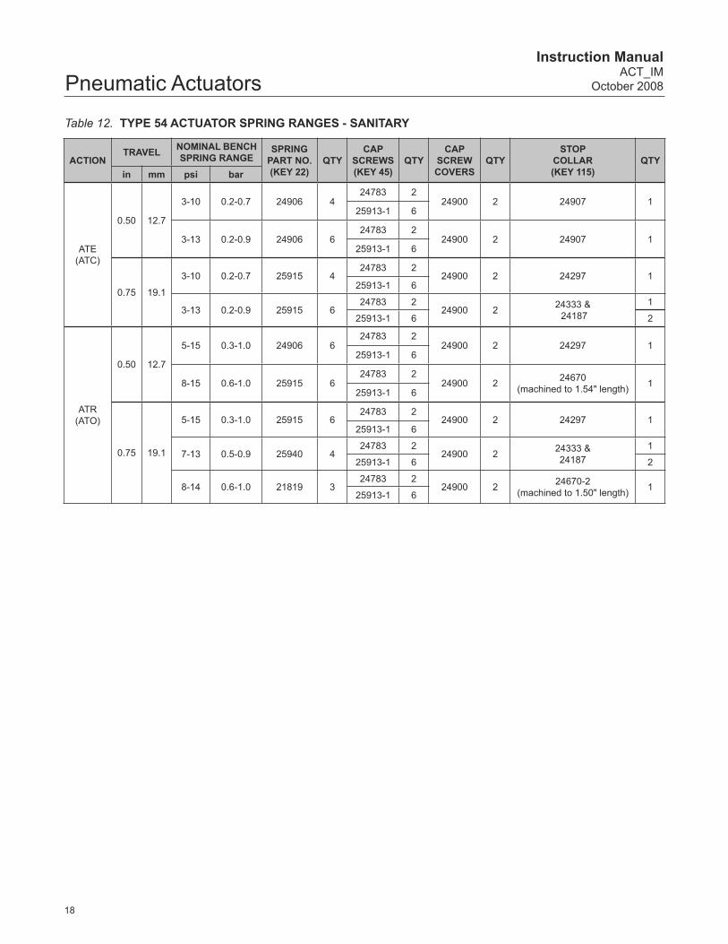
Table 12. TYPE 54 ACTUATOR SPRING RANGES - SANITARY
ACTIONTRAVEL NOMINAL BENCH
SPRING RANGESPRING
PART NO.(KEY 22)
QTYCAP
SCREWS(KEY 45)
QTYCAP
SCREWCOVERS
QTYSTOP
COLLAR(KEY 115)
QTYin mm psi bar
ATE(ATC)
0.50 12.7
3-10 0.2-0.7 24906 424783 2
24900 2 24907 125913-1 6
3-13 0.2-0.9 24906 624783 2
24900 2 24907 125913-1 6
0.75 19.1
3-10 0.2-0.7 25915 424783 2
24900 2 24297 125913-1 6
3-13 0.2-0.9 25915 624783 2
24900 2 24333 & 24187
1
25913-1 6 2
ATR(ATO)
0.50 12.7
5-15 0.3-1.0 24906 624783 2
24900 2 24297 125913-1 6
8-15 0.6-1.0 25915 624783 2
24900 2 24670(machined to 1.54" length) 1
25913-1 6
0.75 19.1
5-15 0.3-1.0 25915 624783 2
24900 2 24297 125913-1 6
7-13 0.5-0.9 25940 424783 2
24900 2 24333 &24187
1
25913-1 6 2
8-14 0.6-1.0 21819 324783 2
24900 2 24670-2(machined to 1.50" length) 1
25913-1 6

19
Instruction ManualACT_IMOctober 2008 Pneumatic Actuators
Figure 12. Type 54 Actuator, Air-to-Retract (ATR) with Handwheel
Figure 13. Type 54 Actuator, Air-to-Extend (ATE) with Handwheel
Table 14. TYPE 54 ACTUATOR ATE WITH HANDWHEEL PARTS
EB0132
Table 13. TYPE 54 ACTUATOR ATR WITH HANDWHEEL PARTS*
EB0131
KEY NO. DESCRIPTION PART
NO. QTY
26Actuator Stem, 5/16 thread 24601
1Actuator Stem, 3/8 thread 24601-2
44 Diaphragm Case (Upper) 24608 1
49 Spacer 24726 1
83 Nut 24602-1 1
84 Clevis 24603 1
85 Nut, Round Bronze 24604 1
86 Washer 25613 1
87 Screw, Set Socket 24606 2
88 Washer, Flat 24620 1
89 Screw, Socket Head 24619 1
90 Handwheel 24605 1
91 Washer, Flat 25958 1
93 Locking Knob 24607 1
*Standard construction furnishes up and down travel stops.
KEY NO. DESCRIPTION PART
NO. QTY
26Actuator Stem, 5/16 thread 24295 1
Actuator Stem, 3/8 thread 24295-1 1
43 Diaphragm Case (Lower) 24294 1
44 Diaphragm Case (Upper) 24608 1
49 Head Bolt 25987 1
52 HandwheelKit No.25985 153 Roll Pin
55 Stem, Handwheel
58 Nut, Self-Locking 25924 1
59 Adapter 25978 1
60 O-Ring 25926 1
61 Lock-nut 25979 1
63 Roll Pin 25931 1
112 Washer 25918 1
126 Hex Tap Bolt (for dual stop only) 24756-8 3
127 Hex Jam Nut (for dual stop only) 42789 3
Do not continue to turn handwheel after the stem is fully extended (valve fully closed and plug seated) or fully retracted (valve fully open) to avoid damage to the handwheel assembly.
CAUTION

20
Instruction ManualACT_IM
October 2008Pneumatic Actuators
Table 15. TYPE 70 ACTUATOR PARTS
KEY NO. DESCRIPTION PART NO. QTY
17/54Yoke w / guide bushing 24184-10
1Yoke (for Fisher® valves) w / guide bushing 24184-1-1
19 Gasket (standard) 009191-445-883
1Gasket (Hi-Temperature) 009191-445-885
22 Actuator Spring See Table 16 ---
25 Shaft Collar 24732-2 1
26Actuator Stem, 5/16 thread 24330-2
1Actuator Stem, 3/8 thread 24330-3
30 (B) Nyloc, Nut See Key No. 39A
39 (B) Diaphragm See Key No.39A
39A (A)(B) Diaphragm Kit (standard) 24471 1
40 Diaphragm Plate 24350 2
43 Diaphragm Case (Lower) 24310 1
44 Diaphragm Case (Upper) 24317 1
45 Cap Screw (short) See Table 16 ---
46 Nut 24705M 16
50 (B) O-Ring (FKM (Fluorocarbon)) See Key No. 39A
51 Spacer 24724 1
56Travel Indicator Scale (0.5 in travel) 983674-001-250
1Travel Indicator Scale (0.75 in travel) 983674-003-250
57 Machine Screw 971302-003-250 2
62 Serial Plate 983753-001-600 1
64 Cap Screw 971000-007-1 6
112 Washer 25861-24 2
113 Vent Plug 24147 1
115 Stop Collar 24333 1
119 Drive Screw 24686 2
121 Set Screw 24332-1 1
122 Jam Nut 24334 1
125 Adjustment Screw Seat 24331 1
NOTES: A. Recommended Spare Parts B. Diaphragm Kit (39A) includes Locknut (30), O-Ring (50), and Diaphragm (39). These parts are not sold separately.
Figure 14. Type 70 ActuatorEB0133
21
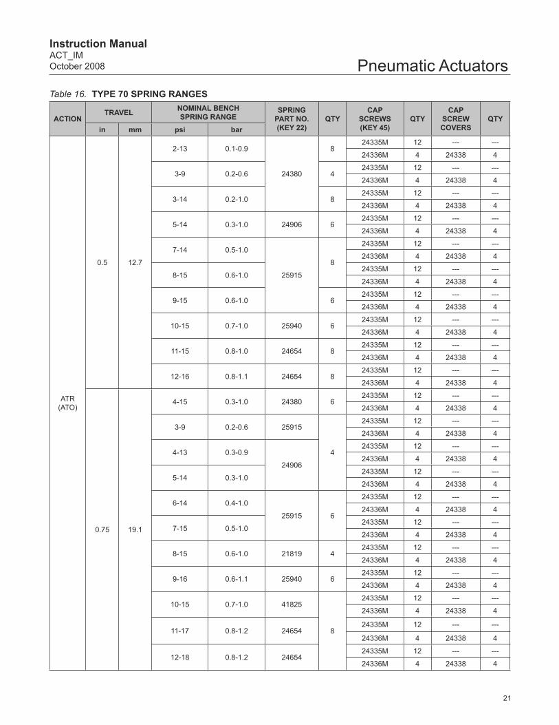
Instruction ManualACT_IMOctober 2008 Pneumatic ActuatorsTable 16. TYPE 70 SPRING RANGES
ACTIONTRAVEL NOMINAL BENCH
SPRING RANGESPRING
PART NO.(KEY 22)
QTYCAP
SCREWS(KEY 45)
QTYCAP
SCREWCOVERS
QTYin mm psi bar
ATR(ATO)
0.5 12.7
2-13 0.1-0.9
24380
824335M 12 --- ---
24336M 4 24338 4
3-9 0.2-0.6 424335M 12 --- ---
24336M 4 24338 4
3-14 0.2-1.0 824335M 12 --- ---
24336M 4 24338 4
5-14 0.3-1.0 24906 624335M 12 --- ---
24336M 4 24338 4
7-14 0.5-1.0
25915
8
24335M 12 --- ---
24336M 4 24338 4
8-15 0.6-1.024335M 12 --- ---
24336M 4 24338 4
9-15 0.6-1.0 624335M 12 --- ---
24336M 4 24338 4
10-15 0.7-1.0 25940 624335M 12 --- ---
24336M 4 24338 4
11-15 0.8-1.0 24654 824335M 12 --- ---
24336M 4 24338 4
12-16 0.8-1.1 24654 824335M 12 --- ---
24336M 4 24338 4
0.75 19.1
4-15 0.3-1.0 24380 624335M 12 --- ---
24336M 4 24338 4
3-9 0.2-0.6 25915
4
24335M 12 --- ---
24336M 4 24338 4
4-13 0.3-0.9
24906
24335M 12 --- ---
24336M 4 24338 4
5-14 0.3-1.024335M 12 --- ---
24336M 4 24338 4
6-14 0.4-1.0
25915 6
24335M 12 --- ---
24336M 4 24338 4
7-15 0.5-1.024335M 12 --- ---
24336M 4 24338 4
8-15 0.6-1.0 21819 424335M 12 --- ---
24336M 4 24338 4
9-16 0.6-1.1 25940 624335M 12 --- ---
24336M 4 24338 4
10-15 0.7-1.0 41825
8
24335M 12 --- ---
24336M 4 24338 4
11-17 0.8-1.2 2465424335M 12 --- ---
24336M 4 24338 4
12-18 0.8-1.2 2465424335M 12 --- ---
24336M 4 24338 4

22
Instruction ManualACT_IM
October 2008Pneumatic Actuators
Figure 15. Dimensional Drawings
Type 32 Actuator Type 54 Actuator Type 70 Actuator
Type 32 Actuator ATO/Fail Closedwith Handwheel
Type 32 Actuator ATC/Fail Open
with Handwheel
Type 54 Actuator ATO/Fail Closedwith Handwheel
Type 54 Actuator ATC/Fail Open
with Handwheel
Type 32 Actuator with Adjustable Open/Close
Dual Travel Stop
Type 16 Actuator
EB0134
EB0135 EB0022

23
Instruction ManualACT_IMOctober 2008 Pneumatic Actuators
This page intentionally left blank.

24
Instruction ManualACT_IM
October 2008Pneumatic Actuators
Fisher and Baumann are marks owned by Fisher Controls International LLC, a member of the Emerson Process Management business division of Emerson Electric Co. Emerson and the Emerson logo are trademarks and service marks of Emerson Electric Co. All other marks are the property of their respective owners. This product may be covered under one or more patents or under pending patent applications.
The contents of this publication are presented for informational purposes only, and while every effort has been made to ensure their accuracy, they are not to be construed as warranties or guarantees, express or implied, regarding the products or services described herein or their use or applicability. We reserve the right to modify or improve the designs or specifi cations of such products at any time without notice.
Neither Emerson, Emerson Process Management, Fisher, nor any of their affi liated entities assumes responsibility for the selection, use, and maintenance of any product. Responsibility for the selection, use, and maintenance of any product remains with the purchaser and end-user.
Emerson Process ManagementFisher Controls International LLCPortsmouth, NH 03801T: 1 (603) 766-8500F: 1 (603) 766-8590www.baumann.com
© Fisher Controls International LLC, 2008; All Rights Reserved. Printed in USA