battlefield damage assessment and repair … · tm 3-251-bd technical manual battlefield damage...
TRANSCRIPT

TM 3-251-BD
TECHNICAL MANUAL
BATTLEFIELD DAMAGE ASSESSMENT
AND REPAIR
FOR
CHEMICAL DEFENSIVE MATERIEL
HEADQUARTERS, DEPARTMENT OF THE ARMY
23 SEPTEMBER 1987 C2

TM 3-251-BDC3
CHANGE
NO. 3
HEADQUARTERSDEPARTMENT OF THE ARMY
WASHINGTON, DC, 31 August 1992
TECHNICAL MANUAL
FOR
BATTLEFIELD DAMAGE ASSESSMENT AND REPAIR
TM 3-251-BD, dated September 1987 and change 1 and 2 are changedas follows:
1. Remove old pages and insert new
2. New or changed material is indicated by a vertical bar in themargin of the page.
Remove Pages
i thru iii (iv blank)11-1 thru 11-7/(11-8 blank)12-1 thru 12-9/(12-10 blank)NoneIndex 1 thru Index 3
(Index 4 blank)
Insert Pages
i thru iii (iv blank)11-1 thru 11-7/(11-8 blank)12-1 thru 12-13/(12-14 blank)15-1 thru 15-7/(15-8 blank)Index 1 thru Index 3
(Index 4 blank)
3. File this change sheet in front of the publication forreference purposes.
By Order of the Secretary of the Army:
O f f i c i a l :
MILTON H. HAMILTONAdministrative Assistant to the
Secretary of the Army02173
GORDON R. SULLIVANGeneral, United States Army
Chief of Staff
DISTRIBUTION:
To be distributed in accordance with DA Form 12-28-E, (Block 0078), Maintenancerequirements for TM 3-251-BD.

TM 3-251-BDC2
CHANGE
NO. 2
HEADQUARTERSDEPARTMENT OF THE ARMY
WASHINGTON, DC, 17 August 1990
TECHNICAL MANUAL
FOR
BATTLEFIELD DAMAGE ASSESSMENT AND REPAIR
TM 3-251-BD, dated 23 September 1987 and change 1 are changed as follows:
1. Remove old pages and insert new pages as indicated below.
2. New or changed material is indicated by a vertical bar in the margin of thepage.
Remove Pages Insert Pages
i thru iii (iv blank)2-17 and 2-1812-1 thru 12-4NoneE-5/(E-6 blank)Index 1 thru Index 3/(Index 4 blank)Front Cover
i thru iii (iv blank)2-17 thru 2-19 (2-20 blank)12-1 thru 12-414-1 thru 14-14E-5 and E-6Index 1 thru Index 3/(Index 4 blank)Front Cover/(Inside FrontCover blank)
3. File this change sheet in front of the publication for reference purposes.
By Order of the Secretary of the Army:
CARL E. VUONOGeneral, United States Army
Chief of Staff
Official:
THOMAS F. SIKORABrigadier General, United States Army
The Adjutant General
Distribution:
To be distributed in accordance with DA Form 12-28 (block 78), maintenancerequirements for TM 3-251-BD.

TM 3-251-BDC1
CHANGE HEADQUARTERSDEPARTMENT OF THE ARMY
No. 1 WASHINGTON, D.C. 1 MAY 1989
OPERATORS, ORGANIZATIONAL, DIRECT SUPPORT/GENERAL SUPPORTMAINTENANCE MANUAL
FOR
BATTLEFIELD DAMAGE ASSESSMENT AND REPAIR
TM 3-251-BD, 23 September 1987, is changed as follows:
1. Remove old pages, and insert new pages as indicated below.
2. New or changed material is indicated by a vertical bar in the margin ofthe page.
Remove Pages Insert Pages
None E-1 through E-5 (E-6 Blank)
3. File this change sheet in front of the publication for reference purposes.
By Order of the Secretary of the Army:
CARL E. VUONOGeneral, United States Army
Chief of Staff
Official:
WILLIAM J. MEEHAN IIBrigadier General, United States Army
The Adjutant General
Distribution:
To be distributed in accordance with DA Form 12-28, requirementsfor TM 3-251-BD.

TM 3-251-BD
This technical manual contains non-standard maintenance procedures. All normalsafety procedures should be observed when the tactical situation permits. Extracare will be taken when the tactical situation requires performing maintenance withammunition up-loaded and when fuels and lubricants are spilled.
RADIATION HAZARD
The cell module of the M43A1 Detector contains a radioactive source (Americium -241 as an oxide) sandwiched between two metal layers as a foil. The cell module ispotentially dangerous if broken.
In any emergency event, contamination must be considered to be present untildetermined otherwise.
HIGH VOLTAGE
High voltage is used in the operation of this equipment.
DEATH ON CONTACT
may result if personnel fail to observe safety precautions. Learn the areascontaining high voltage in each piece of equipment. Be careful not to contact highvoltage connections when installing or operating this equipment. Before workinginside the equipment, turn power off and ground points of high potential beforetouching them.
for artificial respiration, refer to FM 21-11.
a
WARNING
WARNING
WARNING

TM 3-251-BD
WARNING
DANGEROUS CHEMICALS
are used in this equipment.
DEATH
or severe burns may result if personnel fail to observe safety precautions.
CARBON MONOXIDE POISONING CAN KILL YOU
Symptoms of carbon monoxide poisining are headache, dizziness, loss of muscularcontrol, apparent drowsiness, and coma. The following precautions MUST be observedto ensure the safety of the crew.
1. DON’T operate heater or engine in an enclosed area unless ADEQUATELYVENTILATED.
2. DON’T idle engine without maintaining ADEQUATE VENTILATION in vehicle.
3. DON’T drive vehicle with inspection plates, cover plates, or engine accesspanel and doors removed.
4. BE ALERT for exhaust odors and exposure symptoms. If either is present,IMMEDIATELY VENTILATE vehicle. If symptoms persist, remove personnel from vehicleand treat as follows: expose to fresh air; keep warm; DON'T PERMIT PHYSICALEXERCISE; and if necessary, administer artificial respiration.
b
WARNING
TM 3-251-BD
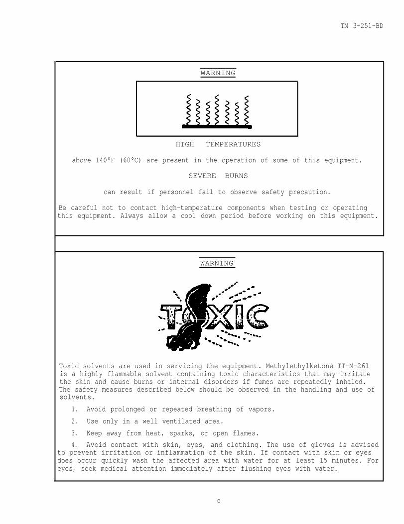
WARNING
HIGH TEMPERATURES
above 140°F (60°C) are present in the operation of some of this equipment.
SEVERE BURNS
can result if personnel fail to observe safety precaution.
Be careful not to contact high-temperature components when testing or operatingthis equipment. Always allow a cool down period before working on this equipment.
WARNING
Toxic solvents are used in servicing the equipment. Methylethylketone TT-M-261is a highly flammable solvent containing toxic characteristics that may irritatethe skin and cause burns or internal disorders if fumes are repeatedly inhaled.The safety measures described below should be observed in the handling and use ofsolvents.
1. Avoid prolonged or repeated breathing of vapors.
2. Use only in a well ventilated area.
3. Keep away from heat, sparks, or open flames.
4. Avoid contact with skin, eyes, and clothing. The use of gloves is advisedto prevent irritation or inflammation of the skin. If contact with skin or eyesdoes occur quickly wash the affected area with water for at least 15 minutes. Foreyes, seek medical attention immediately after flushing eyes with water.
c
TM 3-251-BD
WARNING
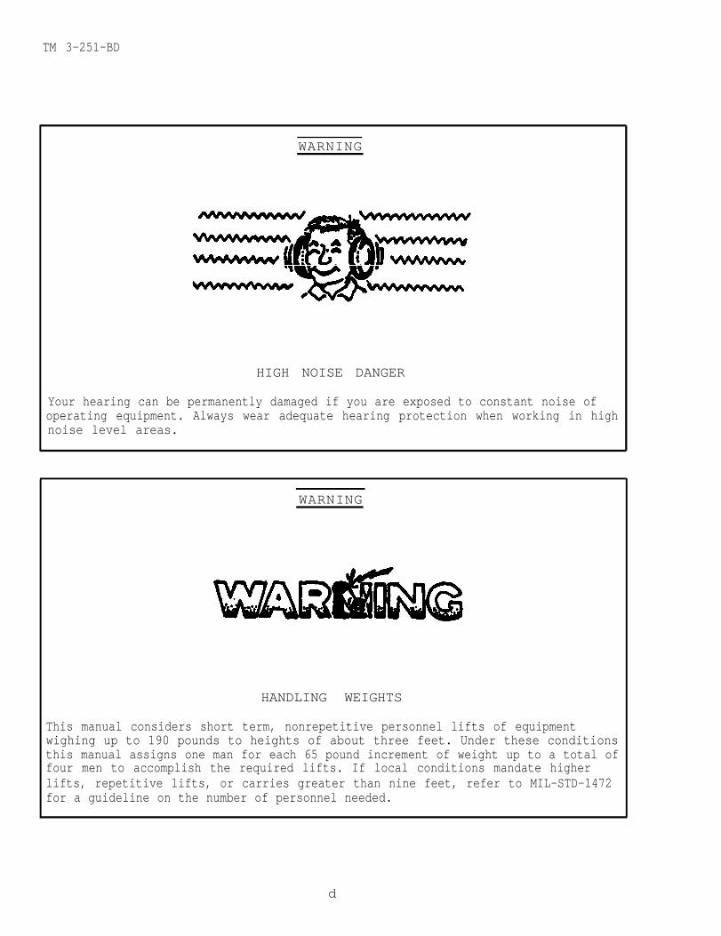
HIGH NOISE DANGER
Your hearing can be permanently damaged if you are exposed to constant noise ofoperating equipment. Always wear adequate hearing protection when working in highnoise level areas.
WARNING
HANDLING WEIGHTS
This manual considers short term, nonrepetitive personnel lifts of equipmentwighing up to 190 pounds to heights of about three feet. Under these conditionsthis manual assigns one man for each 65 pound increment of weight up to a total offour men to accomplish the required lifts. If local conditions mandate higherlifts, repetitive lifts, or carries greater than nine feet, refer to MIL-STD-1472for a guideline on the number of personnel needed.
d

TM 3-251-BD
Technical Manual
No. 3-251-BD
HEADQUARTERSDEPARTMENT OF THE ARMY
Washington,D.C 23 September 1987
Technical Manualfor
BATTLEFIELD DAMAGE ASSESSMENT AND REPAIRDEFENSIVE CHEMICAL EQUIPMENT
Battlefield Damage Assessment and Repair(BDAR)techniques in this manual per-tain to the following end items:
Type A/E32U-8
FILTER UNIT,FILTER UNIT,FILTER UNIT,FILTER UNIT,FILTER UNIT,FILTER UNIT,
Alarm Chemical Agent, Automatic: M8A1 (6665-01-105-5623)DECONTAMINATING APPARATUS, Portable, DS2, 1 1/4 Qt, M11 (4230-00-720-1618)DECONTAMINATING APPARATUS, Power-Driven, 500 Gal, M12A1 (4230-00-926-9488)DECONTAMINATING APPARATUS, Power-Driven, Portable,
(4230-01-153-8660)DECONTAMINATING APPARATUS, Portable, 14 Liter, M13 (4230-01-133-41241DISPERSER, Riot Control Agent, Portable M33A1 (1040-00-148-9824)
Gas-Particulate, Hospital, 6-Man, 12 cfm, M7A1 (4240-00-203-3999)Gas-Particulate, Tank, 3-Man, 12 cfm, M8A2 (4240-00-691-1505)Gas-Particulate, Tank, 3-Man, 12 cfm, M8A3 (4240-00-853-3201)Gas-Particulate, Tank, 5-Man, 20 cfm, M13 (4240-00-601-8372)Gas-Pariculate, Tank, 5-Man, 20 cfm, M13A1 (4240-00-964-9061)Gas-Paticulate, Armored Ambulance, M14 (4240-00-010-5267)
SHELTER SYSTEM, Collective Protection, CB, 10-Man, M51 (4240-00-854-4144)GENERATOR, Smoke, Mechanical: Pulse Jet, M3A4 (1040-01-143-9506)CB HOOD, Mask, Aircraft, M7 (4240-00-021-8695)CB HOOD, Mask, Field, M6A2 (4240-00-999-0420)CB HOOD, Mask, Tank, M5 (4240-00-860-8987)MASK, CB,MASK, CB,MASK, CB,MASK, CB,MASK, CB,MASK, CB,MASK, CB,MASK, CB,
Protective, Aircraft, M24Protective, Field, M17A1Protective, Field, M17A2Protective, Tank, M25A1Attack Helicopter, M43Special Purpose, M9A1Field Mask, M40Combat Vehicle, M42
GENERATOR SET, Smoke, Mechanical: Pulse Jet, M157
(4240-00-776-4384)(4240-00-926-4199)(4240-01-143-2017)(4240-00-994-8751)(4240-01-208-6967)(4240-00-368-6095)(4240-01-258-0062)(4240-01-258-0064)(1040-01-206-0147)
REPORTING ERRORS AND RECOMMENDING IMPROVEMENTS
You can help improve this manual. If you find any mis-takes or if you know of a way to improve the procedures,please let us know. Mail your letter or DA Fom 2028,Recommended Changes to Publications and Blank Forms, orDA Form 2028-2 should be mailed directly to: CommanderChemical Research & Development Center, ATTN: SMCCR-MAT,Aberdeen Proving Ground, MD 21010-5423. A reply will befurnished direct to you.
iChange 3

TM 3-251-BD
CHAPTER
SectionSection
Section
CHAPTER
SectionSection
CHAPTER
SectionSectionSectionSectionSection
CHAPTER
SectionSectionSectionSection
CHAPTER
SectionSection
CHAPTER
SectionSectionSection
CHAPTER
SectionSection
CHAPTER
SectionSection
ii
1.
I.II.
III.
2.
I.II.
3.
I.II.
III.IV.V.
4.
I.II.
III.IV.
5.
I.II.
6.
I.II.
III.
7.
I.II.
8.
I.II.
TABLE OF CONTENTS
GENERAL INFORMATION. . . . . . . . . . . . . . . . . . . . .
Introduction . . . . . . . . . . . . . . . . . . . . . . .Battlefield Damage Assessment and Repair -
Standards and Practices. . . . . . . . . . . . . . . . . Battlefield Damage Assessment and Repair -
Tasks and Responsibilities . . . . . . . . . . . . . .
ASSESSING BATTLEFIELD DAMAGE . . . . . . . . . . . . . .
Introduction . . . . . . . . . . . . . . . . . . . . . .General Fault Assessment Tables . . . . . . . . . . . .
GENERAL REPAIR . . . . . . . . . . . . . . . . . . . . ..
Introduction . . . . . . . . . . . . . . . . . . . . . . . . . Gaskets . . . . . . . . . . . . . . . . . . . . . . . . . . . . . . . .Belts . . . . . . . .. . . . . . . . . . . . . . . . . . . . . . . . . .Housings, Castings and Plates.. . . . . . . . . . . . . . .Brackets and Braces.. . . . . . . . . . . . . . . .
M12A1 DECONTAMINATING APPARATUS . . . . . . . . . . . . . .
Introduction . . . . . . . . . . . . . . . . . . . . . . . . . . . Pump Unit . . . . . . . . . . . . . . . . . . . . . . . . .Water Heater . . . . . . . . . . . . .. . . . . . . . Tank Unit . . . . . . . . . . . . . . . . . . . . . .
Mll DECONTAMINATING APPARATUS . . . . . . . . . . . . . .
Introduction . . . . . . . . . . . . . . . . . . . . . Mll Decontaminating Apparatus . . . . . . . . . . . . . .
TYPE A/E32U-8 DECONTAMINATING APPARATUS . . . . . .
Introduction . . . . . . . . . . . . . . . . . . . . . .Engine . . . . . . . . . . . . . . . . . . . . . . . . .Heat Exchanger . . . . . . . . . . . . . . . . . . . . . .
M13 DECONTAMINATING APPARATUS . . . . . . . . . . . . .
Introduction . . . . . . . . . . . . . . . . . . . . . . M13 Decontaminating Apparatus . . . . . . . . . . . . . .
M3A4 SMOKE GENERATOR . . . . . . . . . . . . . . . . . . . .
Introduction . . . . . . . . . . . . . . . . . . . . . .M3A4 Smoke Generator. . . . . . . . . . . . . . . . .
Change 2
PAGE1-1
1-1
1-4
1-5
2-1
2-12-2
3-1
3-13-13-53-73-9
4-1
4-14-34-164-25
5-1
5-15-2
6-1
6-16-36-9
7-1
7-17-2
8-1
8-18-3
TM 3-251-BD
CHAPTER
SectionSection
CHAPTER
SectionSectionSection
CHAPTER
SectionSection
CHAPTER
SectionSection
CHAPTER
SectionSection
CHAPTER
SectionSection
CHAPTER
9.
I.II.
10.
I.II.
III.
11.
I.II.
12.
I.II.
13.
I.II.
14.
I.II.
15.
APPENDIX A.
APPENDIX B.
APPENDIX C.
APPENDIX D.
APPENDIX E.
INDEX
TABLE OF CONTENTS (CONT)
GAS-PARTICULATE FILTER UNITS: M7A1, M8A2,M8A3, M13, M13A1 and M14 . . . . . . . . . . . . . . . . . . . 9-1
Introduction . . . . . . . . . . . . . . . . . . . . . . . . . . 9-1Gas-Particulate Filter Units: M7A1, M8A2,
M8A3, M13, M13A1 and M14 . . . . . . . . . . . . . . . . . 9-2
M51 SHELTER SYSTEM. . . . . . . . . . . . . . . . . . . . . .10-1
Introduction . . . . . . . . . . . . . . . . . . . . . . . . 10-lEngine . . . . . . . . . . . . . . . . . . . . . . . . . . 10-2Shelter . . . . . . . . . . . . . . . . . . . . . . . . .10-8
HOODS, Chemical-Biological Mask: M5, M6A2,M7, M40 and M42 . . . . . . . . . . . . . . . . . . . . . .
Introduction . . . . . . . . . . . . . . . . . . . . . ..Hoods, Chemical-Biological Mask: M5, M6A2,M7, M40 and M42 . . . . . . . . . . . . . . . . . . .
CHEMICAL-BIOLOGICAL MASKS: M9, M9A1, M17A1,M17A2, M24, M25A1, M40, M42 and M43 . . . . . . . .
Introduction . . . . . . . . . . . . . . . . . . . . Chemical-Biological Masks: M9, M9A1, M17A1,
M17A2, M24, M25A1, M40, M42 and M43 . . . . . . . .
M8A1 AUTOMATIC CHEMICAL AGENT ALARM . . . . . . . . . .
Introduction . . . . . . . . . . . . . . . . . . . . . . .M8A1 Automatic Chemical Agent Alarm . . . . . . . . .
M156 SMOKE GENERATOR. . . . . . . . . . . . . . . . . . . . .
Introduction . . . . . . . . . . . . . . . . . . . . . . . M157 Smoke Generator. . . . . . . . . . . . . . . . . . .
M33A1 Riot Control Agent (RCA) Disperser . . . . .
REFERENCES . . . . . . . . . . . . . . . . . . . . . . . .
SPECIAL OR FABRICATED TOOLS . . . . . . . . . . . . . .
EXPENDABLE/DURABLE SUPPLIES AND MATERIALS . . . .
SUBSTITUTE MATERIAL/PARTS . . . . . . . . . . . . . .
BDAR FIXES AUTHORIZED FOR TRAINING . . . . . . . . . .
11-1
11-1
11-2
12-1
12-1
12-2
13-1
13-113-2
14-1
14-114-2
15-1
A-1
B-1
C-l
D-1
E-1
. . . . . . . . . . . . . . . . . . . . . . . . . . . . . Index 1
Change 3 iii(iv blank)
TM 3-251-BD
CHAPTER 1
GENERAL INFORMATION
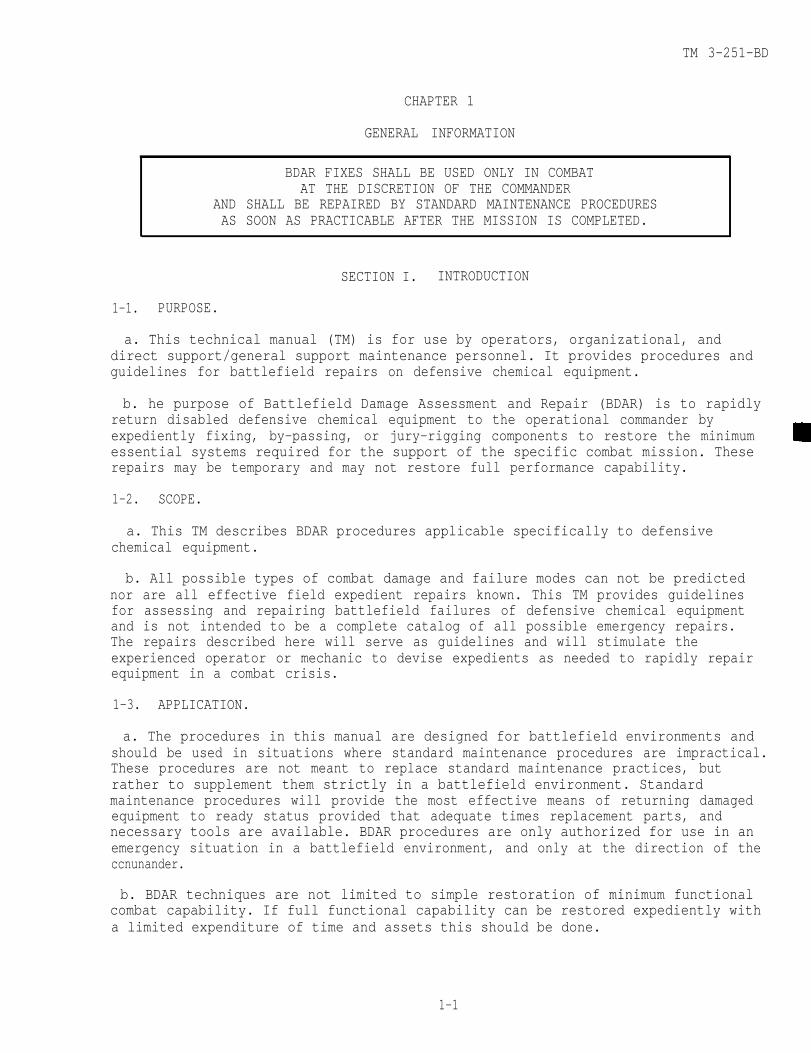
BDAR FIXES SHALL BE USED ONLY IN COMBATAT THE DISCRETION OF THE COMMANDER
AND SHALL BE REPAIRED BY STANDARD MAINTENANCE PROCEDURESAS SOON AS PRACTICABLE AFTER THE MISSION IS COMPLETED.
SECTION I. INTRODUCTION
1-1. PURPOSE.
a. This technical manual (TM) is for use by operators, organizational, anddirect support/general support maintenance personnel. It provides procedures andguidelines for battlefield repairs on defensive chemical equipment.
b. he purpose of Battlefield Damage Assessment and Repair (BDAR) is to rapidlyreturn disabled defensive chemical equipment to the operational commander byexpediently fixing, by-passing, or jury-rigging components to restore the minimumessential systems required for the support of the specific combat mission. Theserepairs may be temporary and may not restore full performance capability.
1-2. SCOPE.
a. This TM describes BDAR procedures applicable specifically to defensivechemical equipment.
b. All possible types of combat damage and failure modes can not be predictednor are all effective field expedient repairs known. This TM provides guidelinesfor assessing and repairing battlefield failures of defensive chemical equipmentand is not intended to be a complete catalog of all possible emergency repairs.The repairs described here will serve as guidelines and will stimulate theexperienced operator or mechanic to devise expedients as needed to rapidly repairequipment in a combat crisis.
1-3. APPLICATION.
a. The procedures in this manual are designed for battlefield environments andshould be used in situations where standard maintenance procedures are impractical.These procedures are not meant to replace standard maintenance practices, butrather to supplement them strictly in a battlefield environment. Standardmaintenance procedures will provide the most effective means of returning damagedequipment to ready status provided that adequate times replacement parts, andnecessary tools are available. BDAR procedures are only authorized for use in anemergency situation in a battlefield environment, and only at the direction of theccnunander.
b. BDAR techniques are not limited to simple restoration of minimum functionalcombat capability. If full functional capability can be restored expediently witha limited expenditure of time and assets this should be done.
1-1

TM 3-251-BDINTRODUCTION
1-3. APPLICATION - CONT.
c. Some of the special techniques in this manual, if applied, may result inshortened life or damage to components of defensive chemical equipment. Thecommander must decide whether the risk of having one less item available for useoutweighs the risk of applying the potentially destructive expedient repairtechnique. Each technique gives appropriate warnings and cautions, and listssystems limitations caused by this action.
1-4. DEFINITIONS.
a. Battlefield Damage. The term battlefield damage includes all Incidents, suchas combat damage, random failures, operator errors, accidents, and wear-out fail-ures which occur on the battlefield and which prevent defensive chemical equipmentfrom accomplishing its mission.
b. Repair or Fix. Repair or fix in this manual includes any expedient actionthat returns a damaged part or assembly to a full or an acceptably degradedoperating condition, including:
(1) Short cuts in parts removal or installation.
(2) Installation of components from other items that can be modified to fit orinterchange with components on the unit.
(3) Repair using parts that serve a non-critical function elsewhere on theunit for the purpose of restoring a critical function.
(4) Bypassing of non-critical components in order to restore basic functionalcapability.
(5) Expeditious cannibalization procedures.
(6) Fabrication of parts from kits or readily available materials.
(7) Jury-rigging.
(8) Use of substitute fuels, fluids, or lubricants.
c. Damage Assessment. Damage assessment is a procedure to rapidly determinewhat is damaged, whether it is repairable, what assets are required to make therepair, who can do the repair (i.e. crew, maintenance team (MT), or maintenancesupport team (MST)), and where the repair should be made. The assessment procedureincludes the following steps:
(1) Determine if the repair can be deferred, or if it must be done.
(2) Isolate the damaged areas and components.
(3) Determine which components must be fixed.
(4) Prescribe fixes.
(5) Determine if parts or components, materials, and tools are available.
1-2

TM 3-251-BDINTRODUCTION
1-4. . DEFINITIONS - CONT.
(6) Estimate the manpower and skill required.
(7) Estimate the total time (clock-hours) required to make the repair.
(8) Establish the priority of the fixes.
(9) Decide where the fix shall be performed.
(10) Decide if recovery is necessary and to what location.
d. Maintenance Team. A Maintenance Team (MT) consists of unit mechanics, whomay be trained in assessing battle damage and field repair procedures. MT iscalled to out-of-action equipment to supplement (or confirm) the crew’s originaldamage assessment. MT assessment determines if field repairs will be conducted orif recovery is required. Depending on available time, the MT will assist the crewin restoring the equipment to mission capability.
e. Maintenance Support Team. A Maintenance Support Team (MST) consists ofdirect support/general support mechanics and technical specialists, who are trainedin assessing battle damage in addition to their speciality. The MST is called bythe MT when equipment damage exceeds MT assessment capability or organizationalrepair capability.
f. MT/MST Assessor. A MT/MST assessor is a senior member of the forward MT/MSTThis person is a systems mechanic/technician trained in BDAR techniques. Thisperson must know:
(1)
(2)
(3)
(4)
(5)
The unit's mission and the commanders requirements.
The maintenance capability of the unit, including the available skills,tools, repair parts, and materials.
How to detect contamination and effect decontamination of equipment.
The unit’s maintenance workload.
The maintenance capability of all accessible rally and maintenancecollection points.
g. Fully Mission Capable. Fully Mission Capable (FMC) means that the equipmentcan perform all its combat missions without endangering the life of the crew. Tobe FMC the equipment must be complete and fully operable with no faults listed inthe "Equipment is not ready/available if" column of the operator’s PreventiveMaintenance Checks and Services (PMCS).
h. Combat Capable. Combat capable means that the equipment meets the minimumfunctional combat capability requirements. (See paragraph 1-10.)
i. Combat Emergency Capable. Combat emergency capable means that the equipmentmeets the needs for specific tactical missions; however, not all systems arefunctional. Also, additional damage due to the nature of an expedient repair mayoccur to the equipment if it is used. The commander must decide if theselimitations are acceptable for that specific emergency situation.
1-3
TM 3-251-BDINTRODUCTION
1-4. DEFINITIONS - CONT.
j. Cannibalization. Cannibalization as used in this TM means any use of repairparts or components obtained from other equipment either damaged or of lowerpriority to the immediate mission. In this TM, the term is used to includecontrolled exchange.
1-5. BDAR RECOMMENDATIONS AND QDR/EIR.
a. Personnel originating new BDAR procedures should forward them directly toCommander, U.S. Army Armament, Munitions and Chemical Command, ATTN: AMSMC-MAR-E(A), Aberdeen Proving Ground, MD 21010-5423. Personnel are encouraged to developand report new BDAR ideas, techniques and procedures.
b. Equipment Improvement Recommendations (EIR) may be submitted by anyone whoknows of an unsatisfactory condition with equipment design or use. You do not haveto show a new design or list a better way to do a procedure, just tell why thedesign is unfavorable or why a procedure is difficult. EIR may be submitted on SF368, Quality Deficiency Report. Mail these directly to Commander, U.S. ArmyArmament, Munitions and Chemical Command, ATTN: AMSMC-MAR-E (A), Aberdeen ProvingGround, MD 21010-5423. A reply will be sent directly to you.
SECTION II. BATTLEFIELD DAMAGE ASSESSMENT AND REPAIR -STANDARDS AND PRACTICES
1-6. BDAR CHARACTERISTICS.
BDAR capability requires simplicity, speed, and effectiveness. Some BDARprocedures include repair techniques that violate standard peacetime maintenancepractices. In a combat emergency situation, greater risks are necessary andacceptable.
1-7. TRAINING.
The unit commander should ensure that an adequate number of members of hisorganization, including supervisors, are trained in BDAR procedures applicable tohis equipment. Each crewman should be trained to perform initial battle damageassessment for his crew position.
1-8. WAIVER OF PRECAUTIONS.
Under combat conditions, BDAR may be performed on chemical equipment which isfueled and/or armed. Other similar precautions may be waived at the discretion ofthe commander.
1-9. ENVIRONMENT.
BDAR may be required in a chemically toxic environment or under other adverseconditions with severe limitations in personnel, facilities, equipment, andmaterials. Performance of repair tasks may be necessary while wearing protectivegear. Expedient decontamination procedures are described in FM 3-5.

TM 3-251-BDINTRODUCTION
1-10. SERVICEABILITY AND OPERABILITY (OPERATING CHARACTERISTICS).
The Minimum Functional Combat Capability (MFCC) criteria for defensive chemicalequipment are as follows:
a. Collective protective equipment reference shall be made to each item.
b. Decontamination equipment reference shall be made to each item.
c. Detection and alarms reference shall be made to each item.
d. Individual protection equipment reference shall be made to each item.
e. Smoke generation equipment reference shall be made to each item.
1-11. PERMANENT REPAIR.
Upon completion of the mission, or at the next practicable opportunity, theequipment will be recovered or evacuated to the appropriate maintenance facilityfor permanent standard repair as required.
SECTION III. BATTLEFIELD DAMAGE ASSESSMENT AND REPAIR -TASKS AND RESPONSIBILITIES
1-12. GENERAL.
a. Battlefield damage assessment and repair procedures are applicable at alllevels from crew through general support maintenance depending on the extent of thedamage, the time available, the skills required, and the parts, components, tools,and materials available. Within these limits, each maintenance level will rapidlytake whatever action is necessary and possible to restore the equipment to thecombat ready condition required for continuation of the mission.
b. Battlefield damage repair kits consisting of essential tools, may be carriedby each unit to enable the crew to rapidly fix the simplest and most common typesof damage/failure.
1-13. COMMANDER AND CREW.
a. The crew of the damaged equipment will make the first assessment immediatelyafter damage has occurred. Crew members will provide the commander with an initialdamage assessment which will include notice of system failure and all major systemsvisibly damaged, inoperative, or impaired. If possible all systems will be checkedat the same time by different crew members. If the failure is due to hostile fire,the report will include the location of impact and the manning status. Immediacyof the report is more important than how long it will take to get back into action.The initial report, therefore, may omit repair time estimates. The commander mustmake an initial out-of-action report to the executive officers post including theseessentials:
(1) Equipment damaged (out-of-action or impaired).
(2) Location of equipment.
1-5

TM 3-251-BDINTRODUCTION
1-13. COMMANDER AND CREW - CONT.
(3) Serviceable status.
(4) Mobility status.
(5) Manning status.
(6) Current and anticipated enemy action.
b. If communication capability is damaged, the commander should approach thenearest friendly radio and make his report.
c. In the forward battle area it is imperative that the crew attempt to move theequipment to a covered or concealed position to prevent additional combat damage,This is the first priority.
d. Battlefield Damage Assessment Procedures are provided in Chapter 2 to permita systematic assessment by crew. Assessment checks include looking at the damagedparts, determining what system they belong to, and deciding how they can be fixedor jury-rigged to permit immediate operation (full or partial).
e. A safety check should be made for any obvious hazards.
f. A functional/operational test should be performed next on those systems whichappear undamaged. For systems with a built-in self-test feature, this will bedone. Only those systems found to be damaged or inoperative, shall be identified.
g. The commander shall report the results of the crew’s damage assessment to theexecutive officer's post, naming the major known causes of the inoperability of theequipment. If repair by crew is possible, he shall report a total estimated repairtime and what functions may be restored.
h. The executive officer’s post will respond with directives and, if required,will call a MT to the location of the damaged equipment for assistance. Ifpossible, sufficient information will be provided to enable the MT to bring anyneeded repair parts or special tools.
i. The crew shall proceed to make any possible field expedient repairs torestore the equipment to the limit of their skills, materials, and tools available.
1-14. UNIT MAINTENANCE TEAMS (MT).
a. The unit maintenance team (MT) and assessor operate out of the company-sizedunit of battalion trains. The MT assessor performs his assessment and themaintenance team completes repairs if possible at the damage site. If the site iswithin direct fire or under enemy observation, movement to a more secure site indefilade may be necessary. This is still considered "on-site".
b. If the equipment has been left unattended in the forward battle area, theimmediate area of the equipment should be checked for mines and the equipmentshould be checked for booby traps before starting the battle damage assessment.
1-6

TM 3-251-BDINTRODUCTION
1-14. UNIT MAINTENANCE TEAMS (MT) - CONT.
C. The MT assessment will be more thorough than the crew's, using unitmaintenance support tools and equipment as needed. MT assessment includes:
(1) Reviewing the crew’s out-of-action report, if available.
(2) Interviewing commander and crew, if available.
(3) Visually inspecting damaged parts and systems.
(4) Performing a self-test.
(5) Making tests with organizational test equipment, if required.
(6) Performing additional equipment operational tests, as necessary.
d. Using this information and following the steps of paragraph 1-4c, the MTwill:
(1) Determine what must be repaired or replaced.
(2) Determine sequence and priority of repair actions.
(3) Estimate repair times for each repair task.
(4) Total the repair task times and determine if the repairs can be performedin the time available.
(5) Determine repair location and, if other than on-site, arrange for recoveryof the equipment to the repair site.
e. If all critical repairs can be made within the available time with theskills, materials, tools, and equipment at hand, the MT, assisted by the crew, willproceed with the on-site repair.
f. If the damage exceeds the repair capability of the MT, and time is availablefor an MST on-site fix, the MST shall be called.
g. If time for an MST on-site fix is not available, but the equipment isrepairable, the MT shall provide for recovery of the vehicle to a designatedcollection point.
h. If the equipment is not repairable, the MT shall provide for one of thefollowing:
(1) Recovery to a maintenance collection point for evacuation to the rear.
(2) On-site stripping (if approved by Commander, coordinated with supportmaintenance).
(3) Abandonment/destruction (if directed by commander).
1-7

TM 3-251-BDINTRODUCTION
1-14. UNIT MAINTENANCE TEAMS (MT) - CONT.
i. Some equipment should never be abandoned if recovery/evacuation is possiblebecause some equipment can almost always be rebuilt, no matter how badly damaged.If the equipment is damaged catastrophically and evacuation is not possible, removeitems in the following order:
(1) Needed spares on-site.
(2) Sensitive, high value, limited size items.
(3) Other needed spares or repair parts.
j. If the equipment is contaminated, the MT shall mark the equipment withcontamination markers and arrange for recovery to a decontamination site.
1-15. DIRECT SUPPORT/GENERAL MAINTENANCE SUPPORT TEAM (MST).
a. The MST shall assist the MT as needed, using direct support maintenance toolsand equipment. MST assessment and repair procedures are the same as those of theMT except at a higher level. If possible, the MT will tell the MSTwhat tools and spare parts are needed to perform the repairs. While waiting forthe MST to arrive, the crew, under the supervision of the MT, will open up theequipment and make it ready for the MST to perform the BDAR when it arrives.
b. Damaged equipment removed to designated repair sites shall be selected forrepair by the MST in order of:
(1) Most essential to the completion of the mission.
(2) Can be repaired in the least amount of time.
1-16. TIME LIMITS FOR REPAIRING DAMAGE.
a. In combat, the time available for BDAR is limited. One of the factors to beconsidered in the selection of a repair site is the amount of time available at thesite based on the tactical situation. The assessment includes an estimate of totalelapsed time for all tasks required to restore the equipment. The time availableat the selected repair site must equal or exceed the estimated time required toaccomplish all tasks associated with the BDAR.
b. Determining where BDAR will take place should be based on the guidelines inTable 1-1. These are general rules which must be adjusted by the commander basedon his best estimate of how the most responsive maintenance support can beprovided. He must consider the tactical situation, maintenance backlog, personnel,tools, TMDE, and repair parts available. The guidelines are based on a defensivescenario and can be extended when applied to the offense.
1-8

1-16. TIME LIMITS FOR REPAIRING DAMAGE - CONT.
Table 1-1. Summary of BDAR Time Guidelines
Location
Breakdown Site
Battalion TrainsOrganizationalMaintenanceCommand Post(OMCP)
Brigade SupportArea
Division SupportArea
Corps Support
Elements performing BDAR
1.2.3.
1.2.
3.
1.2.
3.
1.2.
1.
Operator/CrewBattalion Maintenance Team (MT)Maintenance Support Team (MST) fromForward Support Maintenance Company
Battalion Maintenance PlatoonMaintenance Support Team (MST) fromForward Support Maintenance CompanyMaintenance Support Team (MST) fromMaintenance Battalion
Forward Support Maintenance Co.Maintenance Support Team (MST) fromMaintenance BattalionMaintenance Support Team (MST) fromCombat Support Command (COSCOM)
Maintenance BattalionMaintenance Support Team (MST) fromCOSCOM
COSCOM Maintenance Companies
TM 3-251-BDINTRODUCTION
Time guidelines
2 hours
6 hours
24 hours
36 hours
96 hours
1-17. RECORDING BDAR REPAIRS.
a. All equipment parts, which are repaired using BDAR or other expedienttechniques, shall be marked with a tag, DD Form 1577, or similar conspicuous tag.It is not necessary to fill out the form. The purpose of marking an item which hasbeen repaired using BDAR techniques is to quickly enable mechanics to recognizethese parts when the equipment is subsequently returned for authorized permanentrepair.
b. Since it is impractical to attach tags to expediently repaired componentslocated on the outside of the equipment, the fix shall be noted on DD Form 1577 orsimilar tag, and the tags stored in the compartment normally reserved for theequipment log book.
c. A tag should also be placed conspicuously on the equipment when a BDARprocedure has resulted in a degraded operating capability. This tag should bemarked "BDAR" and noted with its specific limitations or cautions.
d. When a component is cannibalized from a repairable piece of equipment,a tag should be attached in the space created by the missing part to alertdownstream repair personnel quickly that the part has been removed.
1-9
TM 3-251-BDINTRODUCTION
1-17. RECORDING BDAR REPAIRS - CONT.
e. When the equipment is recovered/evacuated for permanent standard repair, andDA Forms 2404 and 2407 are used, the notation “BDAR” shall be added in the spaceprovided for description of deficiencies.
f. DA PAM 738-750 provides for disposition of DA Form 2404 and copy number 3 ofDA Form 2407. When “BDAR” is noted on these forms, they shall be mailed to:Survivability/Vulnerability Information Analysis Center, FIES/SURVIAC, WrightPatterson AFB, OH 45433. The information on these forms will provide data fordesigning equipment to be less susceptible to combat damage and easier to repairwhen damaged.
1-10

TM 3-251-BD
CHAPTER 2
ASSESSING BATTLEFIELD DAMAGE
BDAR FIXES SHALL BE USED ONLY IN COMBATAT THE DISCRETION OF THE COMMANDER
AND SHALL BE REPAIRED BY STANDARD MAINTENANCE PROCEDURESAS SOON AS PRACTICABLE AFTER THE MISSION IS COMPLETED.
SECTION I. INTRODUCTION
2-1. SCOPE .
This chapter provides guidelines to use to assess battlefield damage to defensivechemical equipment. It directs you to an expedient repair procedure, or to thestandard system TM if an expedient repair procedure for your problem doesn’t exist.
2-2. GENERAL .
Use this TM in conjunction with the equipment's Technical Manuals (TM). Thischapter explains how to use this manual to assess and fix battlefield damage thatprevents the equipment from functioning. This chapter contains the general faultassessment tables, general troubleshooting, and maintenance instructions includingbattlefield damage assessment/repair forms. General fault assessment tables,specific fault assessment tables, and detailed assessment procedures are used tolocate the damage; and an expedient repair procedure tells how to fix the damage.An index of the expedient repair procedures is located in each chapter. If youdon’t know or aren’t sure exactly what your problem is, you should use theassessment tables and procedures to find the fault.
2-3. APPLICATION.
Use the following steps to find and fix battlefield damages:
a. Do the Preventive Maintenance Checks and Services (PMCS) in the TM. At thesame time look for obvious damage to the equipment.
b. If applicable, do the troubleshooting/repair recommended in the TM.
c. If you find the problem, determine its effect on the operation of the item.
d. If you can’t fix the problem using the PMCS's and procedures in the standardTM, use the assessment tables to assess and fix the problem.
e. If the problem does not affect equipment operation, the commander will decidewhether to attempt to fix the problem or continue with the mission.
f. If the damage does affect equipment operation, do one of the following:
(1) Replace the bad part/assembly with a good one (from supply or othersource).
2-1

TM 3-251-BDASSESSING BATTLEFIELD DAMAGE
2-3. APPLICATION - CONT.
(2) Replace the bad part/assembly with a substitute, if one exists.
(3) Use the expedient repair procedures in this manual to repair the damage.
SECTION II. GENERAL FAULT ASSESSMENT TABLES
2-4. GENERAL.
a. This section provides an overall damage assessment procedure to evaluate thefunctional capability of defensive chemical equipment.
b. The assessment procedures are designed to ensure that all necessary aspectsof defensive chemical equipment capability are evaluated during the assessmentprocess. The procedures refer you to:
(1) procedures in this manual if a “quick-fix” is possible,
(2) the standard TM if the best repair is covered in the system TM, or
(3) a higher maintenance level if access to devices or materials to do thequick-fix are available only at those levels.
c. Each procedure:
(1)
(2)
(3)
(4)
(5)
contains general information about the problem.
lists materials and/or tools required other than those commonly availableto the crew, MT, and MST (If the listed items are not available,improvise. Anything that will do the job is acceptable.)
lists the estimated number of soldiers needed and the estimated timerequired to complete the repair,
states the operational limitations caused by the repair action beforeexperiencing further damage/degradation to the equipment,
provides other expedient options you can use depending on the availabilityof personnel, materials, tools, and/or time. (This does not includestandard maintenance procedures or recovery.)
d. Following each assessment procedure is an index of the procedures containedin that chapter. If you know exactly what your problem is, you can use the indexto find the proper expedient repair procedure.
e. Additional data is contained in the appendices.
(1) Appendix A lists publications referenced in TM text.
(2) Appendix B lists special or fabricated tools used in performing BDARrepairs.
2-2
TM 3-251-BDASSESSING BATTLEFIELD DAMAGE
2-4. GENERAL - CONT.
(3) Appendix C contains lists of expendable/durable supplies and materialsthat are available for BDAR fixes.
(4) Appendix D lists substitute materials/parts that maybe used for BDARfixes.
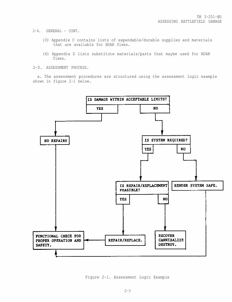
2-5. ASSESSMENT PROCESS.
a. The assessment procedures are structured using the assessment logic exampleshown in figure 2-1 below.
Figure 2-1. Assessment Logic Example
2-3

TM 3-251-BDASSESSING BATTLEFIELD DAMAGE
2-5. ASSESSMENT PROCESS - CONT.
b. All assessment procedures follow the sequence:
(1) visually inspect (repair, if necessary),
(2) functionally test (repair, if necessary) and,
(3) assess the performance.
The field fixes will enable the crew to continue operations in some cases, but willusually be most useful to the MT/MST for scheduling and accomplishing fix-forwardrepairs and assessing combat capabilities for reporting to commanders.
c. There are three kinds of assessments performed on damaged equipment.
(1) The first assessment is extent and kind of damage and how it affectsequipment operation and capabilities.
(2) The second is whether the damage needs to be repaired.
(3) The third is assessment of where and how to repair the damage.
d. Assessments of damage may be made in turn by operator/crew, MT, and MSTassessors.
(1) Extent and kind of damage is readily assessable.
(2) Whether or not to repair the damage may be readily assessable. However,whether to attempt repair and when and how to repair the damage may bejudgment calls. No procedure can take all possible situations intoaccount. Assessment of whether the damage needs to be repaired will bemade jointly by the MT and the commander as they evaluate the equipmentfor further operation or recovery.
(3) Assessment of where and how to repair the damage will be made by the MTusually with some suggestions by crew/operator. MST’s may redirect orchange MT’s decisions.
2-6. OVERALL EQUIPMENT ASSESSMENT PROCEDURES.
a. This procedure can be used by the crew, but it will be of more use to an MTor MST assessor working to “quick-fix” equipment for a mission. The procedureprovides for assessing the kind of damage and determining:
(1) the effect of the damage and if it needs to be fixed,
(2) if the damage can be fixed using BDAR or if only regular maintenanceoperations can fix it, and
(3) how long it will take to fix it.
2-4

TM 3-251-BDASSESSING BATTLEFIELD DAMAGE
2-6. OVERALL EQUIPMENT ASSESSMENT PROCEDURES - CONT.
b. This is accomplished by structuring this manual In rank order, from theequipment function overview down to the specific. Each major function and eachsubsystem that makes up a part of providing that function, has a stand-aloneassessment procedure to make it easier to quantify each significant problemencountered in battlefield damaged equipment.
c. As an example, a M12A1 Decontaminating Apparatus develops an engine fuelcontrol problem. The overall assessment table directs the user to perform a numberof visual and functional checks, which will narrow down the number of areaspossible at fault. The overall assessment table provides references to chapterand/or sections dealing with a subsystem in which the problem may be found.Additional assessment procedures in that chapter will either eliminate furtherassessment in that area or confirm the likelihood of a problem in that area bydirecting the user to check out specific assemblies or components. Assessmentprocedures in the beginning of each chapter provide references to specificparagraphs which may expediently solve the problem.
d. At any point on each of the assessment levels, the assessor can abort theprocedure and initiate other actions if the tactical situation dictates.
e. Refer to table 2-1, Chemical Equipment Assessment, to begin the assessmentprocess.
2-5
TM 3-251-BDASSESSING BATTLEFIELD DAMAGE
2-6. OVERALL EQUIPMENT ASSESSMENT PROCEDURES - CONT.
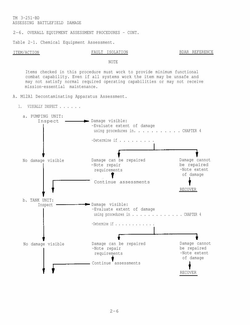
Table 2-1. Chemical Equipment Assessment.
ITEM/ACTION FAULT ISOLATION
mission-essential maintenance.
NOTE
Items checked in this procedure must work to provide minimum functionalcombat capability. Even if all systems work the item may be unsafe andmay not satisfy normal required operating capabilities or may not receive
A. M12A1 Decontaminating Apparatus Assessment.
1. VISUALLY INSPECT . . . . . .
a. PUMPING UNIT:Inspect
No damage visible
BDAR REFERENCE
Damage visible:-Evaluate extent of damageusing procedures in. . . . . . . . . . . CHAPTER 4
-Determine if . . . . . . . . .
Damage can be repaired Damage cannot-Note repair be repairedrequirements -Note extent
of damage
b. TANK UNIT:Inspect
No damage visible
RECOVER
Damage visible:-Evaluate extent of damageusing procedures in . . . . . . . . . . . . . CHAPTER 4
-Determine if . . . . . . . . . . . .
Damage can be repaired Damage cannot-Note repair be repairedrequirements -Note extent
of damageContinue assessments
RECOVER
Continue assessments
2-6

TM 3-251-BDASSESSING BATTLEFIELD DAMAGE
2-6. OVERALL EQUIPMENT ASSESSMENT PROCEDURES - CONT.
Table 2-1. Chemical Equipment Assessment - Cont.
ITEM/ACTION FAULT ISOLATION BDAR REFERENCE
c. WATER HEATER:Inspect Damage visible:
-Evaluate extent of damageusing procedures in. . . . . . . . . . . . . . CHAPTER 4
-Determine if . . . . . . . . . . . . . .
No damage found Damage can be repaired Damage cannot-Note repair be repairedrequirements -Note extent
of damage
Continue assessments
RECOVER
2. FUNCTIONALLY TEST . . . . .
a. PUMPING UNIT:Test reveals Engine damage:
-Evaluate extent of damageusing procedures in . . . . . . . . . . . . CHAPTER 4
Pump damage:-Evaluate extent of damageusing procedures In . . . . . . . . . . . . CHAPTER 4
No damage found
-Determine if . . . . . . . . . . . . .
Damage can be repaired Damage cannot-Note repair be repairedrequirements -Note extent
of damage
Continue assessments
RECOVER
2-7
TM 3-251-BDASSESSING BATTLEFIELD DAMAGE
2-6. OVERALL EQUIPMENT ASSESSMENT PROCEDURES - CONT.
Table 2-1. Chemical Equipment Assessment - Cont.
ITEM/ACTION FAULT ISOLATION
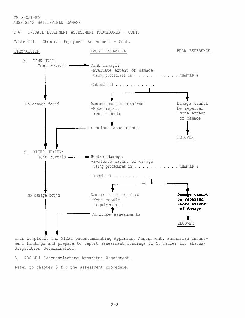
b. TANK UNIT:Test reveals
No damage found
c. WATER HEATER:Test reveals
No damage found
BDAR REFERENCE
Tank damage:-Evaluate extent of damageusing procedures In . . . . . . . . . . . CHAPTER 4
-Determine if . . . . . . . . . . .
Damage can be repaired Damage cannot-Note repair be repairedrequirements -Note extent
of damage
Continue assessments
RECOVER
Heater damage:-Evaluate extent of damageusing procedures in . . . . . . . . . . . CHAPTER 4
-Determine if . . . . . . . . . . . .
-Note repairrequirements
Continue assessments
RECOVER
This completes the M12A1 Decontaminating Apparatus Assessment. Summarize assess-ment findings and prepare to report assessment findings to Commander for status/disposition determination.
B. ABC-M11 Decontaminating Apparatus Assessment.
Refer to chapter 5 for the assessment procedure.
Damage can be repaired
2-8

TM 3-251-BDASSESSING BATTLEFIELD DAMAGE
2-6. OVERALL EQUIPMENT ASSESSMENT PROCEDURES - CONT.
Table 2-1. Chemical Equipment Assessment - Cont.
ITEM/ACTION FAULT ISOLATION BDAR REFERENCE
C. TYPE A/E32U-8 Decontaminating Apparatus Assessment.
1. VISUALLY INSPECT . . . . . .
a. ENGINE:Inspect Damage visible:
-Evaluate extent of damageusing procedures in . . . . . . . . . . . . . . CHAPTER 6
No damage visible Damage can be repaired Damage cannot-Note repair be repairedrequirements -Note extent
of damageContinue assessments
RECOVER
b. HEAT EXCHANGER:Inspect Damage visible:
-Evaluate extent of damageusing procedures in . . . . . . . . . . . . . . . . CHAPTER 6
No damage visible Damage can be repaired Damage cannot-Note repair be repairedrequirements -Note extent
of damageContinue assessments
RECOVER
2-9
-Determine if . . . . . . . . . . . .
-Determine if . . . . . . . .

TM 3-251-BDASSESSING BATTLEFIELD DAMAGE
2-6. OVERALL EQUIPMENT ASSESSMENT PROCEDURES - CONT.
Table 2-1. Chemical Equipment Assessment - Cont.
ITEM/ACTION FAULT ISOLATION BDAR REFERENCE
2. FUNCTIONALLY TEST . . . .
a. ENGINE:Test reveals Engine damage:
-Evaluate extent of damageusing procedures in. . . . . . . . . . . CHAPTER 6
-Determine if . . . . . . . . . . . . . .
No damage found Damage can be repaired-Note repairrequirements
Damage cannotbe repaired-Note extentof damage
Continue assessments
RECOVER
b. HEAT EXCHANGER:Test reveals Heat exchanger:
-Evaluate extent of damageusing procedures in . . . . . . . . . . CHAPTER 6
-Determine if . . . . . . . . . . . . . .
No damage found-Note repair be repairedrequirements -Note extent
of damage
Continue assessments
RECOVER
Damage can be repaired
This completes the TYPE A/E32U-8 Decontaminating Apparatus Assessment. Summarizeassessment findings and prepare to report assessment findings to Commander forstatus/disposition determination.
D. M13 Decontaminating Apparatus Assessment.
Refer to chaper 7 for the assessment procedure.
2-10
Damage cannot

TM 3-251-BDASSESSING BATTLEFIELD DAMAGE
2-6. OVERALL EQUIPMENT ASSESSMENT PROCEDURES - CONT.
Table 2-1. Chemical Equipment Assessment - Cont.
ITEM/ACTION FAULT ISOLATION BDAR REFERENCE
E. M3A4 Smoke Generator Assessment.
1. VISUALLY INSPECT . . . . . .
a. FUEL SYSTEM:Inspect Damage visible:
-Evaluate extent of damageusing procedures in . . . . . . . . . . . . CHAPTER 8
-Determine if . . . . . . . . . . . .
No damage visible Damage can be repaired Damage cannot-Note repair be repairedrequirements -Note extent
of damageContinue assessments
RECOVER
b. INDICATOR SYSTEM:Inspect Damage visible:
-Evaluate extent of damageusing procedures in, . . . . . . . . . . . . . . CHAPTER 8
-Determine if . . . . . . . . . . . .
No damage visible-Note repair be repairedrequirements -Note extent
of damageContinue assessments
RECOVER
Damage can be repaired
c. FOG OIL SYSTEM:Inspect Damage visible:
-Evaluate extent of damageusing procedures in . . . . . . . . . . . . . . . CHAPTER 8
-Determine if . . . . . . . . . . . . .
No damage visible Damage can be repaired Damage cannot-Note repair be repairedrequirements -Note extent
of damageContinue assessments
RECOVER
Damage cannot
2-11

TM 3-251-BDASSESSING BATTLEFIELD DAMAGE
2-6. OVERALL EQUIPMENT ASSESSMENT PROCEDURES - CONT.
Table 2-1. Chemical Equipment Assessment - Cont.
ITEM/ACTION FAULT ISOLATION BDAR REFERENCE
d. AIR PRESSURE SYSTEM:Inspect Damage visible:
-Evaluate extent of damageusing procedures in . . . . . . CHAPTER 8
-Determine if . . . . . . . . . . . . .
No damage found Damage can be repaired Damage cannot-Note repair be repairedrequirements -Note extent
of damageContinue assessments
RECOVER
e. IGNITION MAGNETO:Inspect Damage visible:
-Evaluate extent of damageusing procedures in . . . . . . . CHAPTER 8
-Determine if . . . . . . . . . . .
No damage found Damage can be repaired Damage cannot-Note repair be repairedrequirements -Note extent
of damageContinue assessments
RECOVER
2. FUNCTIONALLY TEST . . . . .
a. FUEL SYSTEM:Test reveals Fuel system damage:
-Evaluate extent of damageusing procedures in . . . . . . CHAPTER 8
-Determine if . . . . . . . . . . . . .
No damage found Damage can be repaired-Note repair be repairedrequirements -Note extent
of damageContinue assessments
Damage cannot
RECOVER
2-12
TM 3-251-BDASSESSING BATTLEFIELD DAMAGE
2-6. OVERALL EQUIPMENT ASSESSMENT PROCEDURES - CONT.
Table 2-1. Chemical Equipment Assessment - Cont.
ITEM/ACTION FAULT ISOLATION BDAR REFERENCE
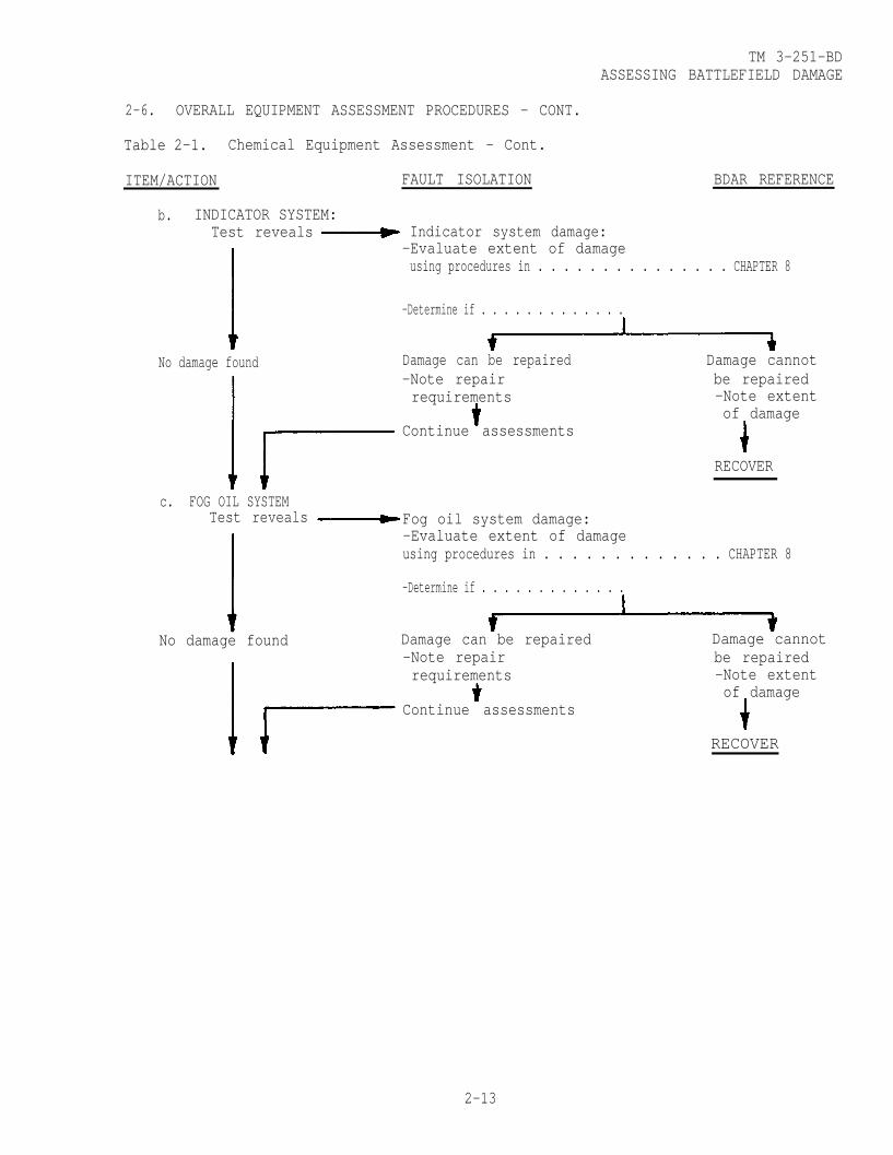
b. INDICATOR SYSTEM:Test reveals Indicator system damage:
-Evaluate extent of damageusing procedures in . . . . . . . . . . . . . . . CHAPTER 8
No damage found
c. FOG OIL SYSTEM
-Determine if . . . . . . . . . . . . .
-Note repair be repairedrequirements -Note extent
of damageContinue assessments
Damage cannot
RECOVER
Fog oil system damage:-Evaluate extent of damageusing procedures in . . . . . . . . . . . . . CHAPTER 8
-Determine if . . . . . . . . . . . . .
No damage found-Note repair be repairedrequirements -Note extent
of damageContinue assessments
RECOVER
Damage can be repaired
2-13
Damage can be repaired
Test reveals
Damage cannot
BDAR REFERENCE
TM 3-251-BDASSESSING BATTLEFIELD DAMAGE
2-6. OVERALL EQUIPMENT ASSESSMENT PROCEDURES - CONT.
Table 2-1. Chemical Equipment Assessment - Cont.
ITEM/ACTION FAULT ISOLATION
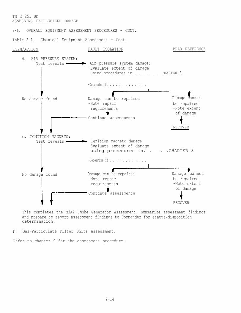
d. AIR PRESSURE SYSTEM:Test reveals Air pressure system damage:
-Evaluate extent of damageusing procedures in . . . . . . CHAPTER 8
-Determine if . . . . . . . . . . . .
No damage found Damage can be repaired-Note repair be repairedrequirements -Note extent
of damageContinue assessments
RECOVER
e. IGNITION MAGNETO:Test reveals Ignition magneto damage:
-Evaluate extent of damageusing procedures in. . . . .CHAPTER 8
-Determine if . . . . . . . . . . . .
No damage found Damage can be repaired Damage cannot-Note repair be repairedrequirements -Note extent
of damageContinue assessments
RECOVER
This completes the M3A4 Smoke Generator Assessment. Summarize assessment findingsand prepare to report assessment findings to Commander for status/disposition
F. Gas-Particulate Filter Units Assessment.
Refer to chapter 9 for the assessment procedure.
2-14
Damage cannot
determination.
TM 3-251-BDASSESSING BATTLEFIELD DAMAGE
2-6. OVERALL EQUIPMENT ASSESSMENT PROCEDURES - CONT.
Table 2-1. Chemical Equipment Assessment - Cont.
ITEM/ACTION FAULT ISOLATION BDAR REFERENCE
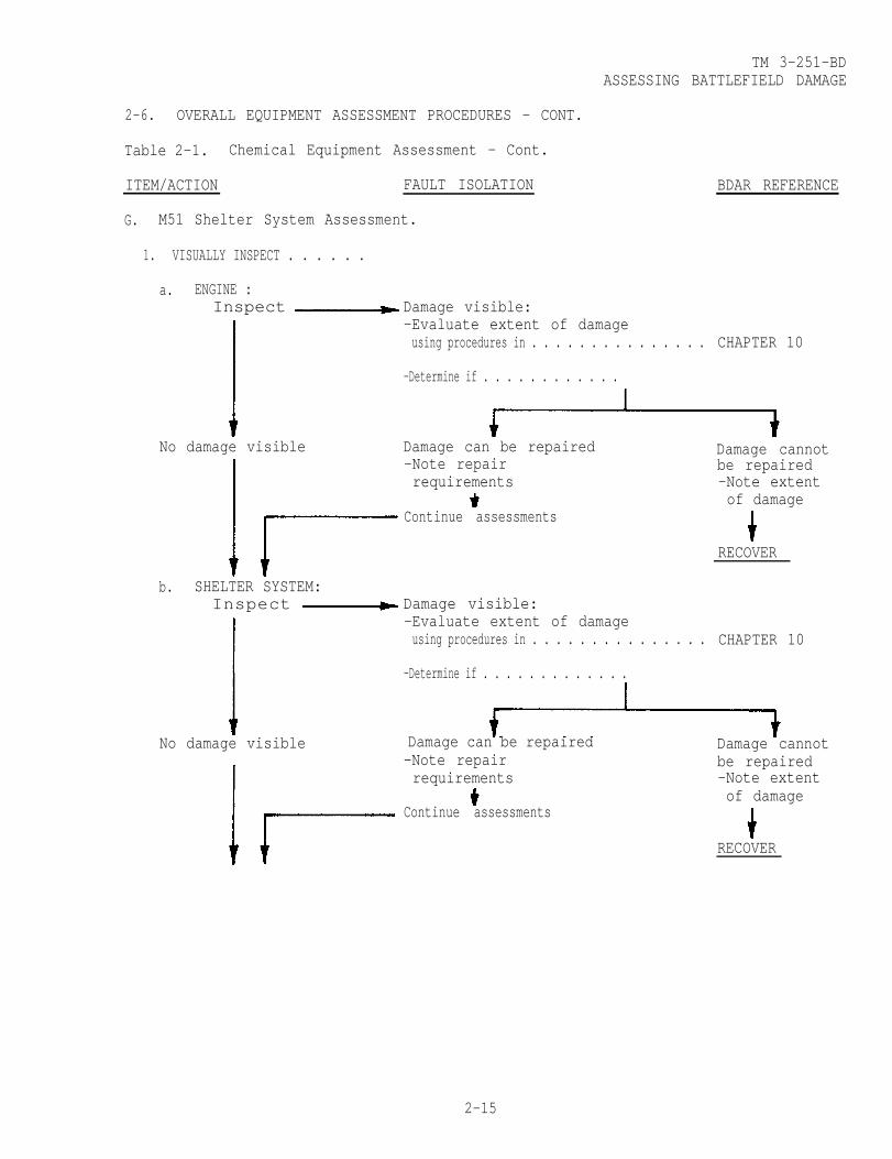
G. M51 Shelter System Assessment.
1. VISUALLY INSPECT . . . . . .
a. ENGINE :Inspect Damage visible:
-Evaluate extent of damageusing procedures in . . . . . . . . . . . . . . . CHAPTER 10
-Determine if . . . . . . . . . . . .
No damage visible Damage can be repaired-Note repair be repairedrequirements -Note extent
of damageContinue assessments
RECOVER
b. SHELTER SYSTEM:Inspect Damage visible:
-Evaluate extent of damageusing procedures in . . . . . . . . . . . . . . . CHAPTER 10
Damage cannot
-Determine if . . . . . . . . . . . . .
No damage visible Damage cannot-Note repair be repairedrequirements -Note extent
of damageContinue assessments
RECOVER
Damage can be repaired
2-15

TM 3-251-BDASSESSING BATTLEFIELD DAMAGE
2-6. OVERALL EQUIPMENT ASSESSMENT PROCEDURES - CONT.
Table 2-1. Chemical Equipment Assessment - Cont.
ITEM/ACTION FAULT ISOLATION
2. FUNCTIONALLY TEST . . . . .
a. ENGINE UNIT: Electrical system damage:Test reveals
No damage found
b. SHELTER:Test reveals
BDAR REFERENCE
—Evaluate extent of damageusing procedures In . . . . . . . . . . . . . CHAPTER 10
Fuel system damage:-Evaluate extent of damageusing procedures In. . . . . . . . . . . . . CHAPTER 8
-Determine if . . . . . . . . . .
-Note repair be repairedrequirements -Note extent
of damageContinue assessments
RECOVER
Electrical system damage:-Evaluate extent of damageusing procedures in......... CHAPTER 10
Pressurization system damage:-Evaluate extent of damageusing procedures in . . . . . . . . . . . . CHAPTER 10
Environmental control system damage:-Evaluate extent of damageusing procedures in. . . . . . . . . . . . CHAPTER 10
-Determine if . . . . . . . . . . . . . .
No damage found Damage can be repaired Damage cannot-Note repair be repairedrequirements -Note extent
of damageContinue assessments
RECOVER
This completes the M51 Shelter Syster Assessment. Summarize assessment findingsand prepare to report assessment findings to Commander for status/disposition
Damage can be repaired Damaged cannot
determination.
2-16

CHAPTER 14
CHAPTER 14
TM 3-251-BDASSESSING BATTLEFIELD DAMAGE
2-6. OVERALL EQUIPMENT ASSESSMENT PROCEDURES (CONT)
Table 2-1. Chemical Equipment Assessment (Cont)
ITEM/ACTION FAULT ISOLATION BDAR REFERENCE
H. Mask Hood Assessment. Refer to Chapter ll for the assessment procedure.
I. Chemical-Biological Protective Mask Assessment. Refer to Chapter 12 forthe assessment procedure.
J. Chemical Agent Alarm Assessment. Refer to Chapter 13 for the assessment.
2-17
procedure.
K.M157 Smoke Generator Assessment.
Change 2

TM 3-251-BDASSESSING BATTLEFIELD DAMAGE
2-6. OVERALL EQUIPMENT ASSESSMENT PROCEDURES. (CONT)
Table 2-1. Chemical Equipment Assessment (Cont)
ITEM/ACTION FAULT ISOLATION BDAR REFERENCE
c. FOG OIL SYSTEM:
No damage visible
2. FUNCTIONALLY TEST . . . .
b. FUEL SYSTEM:Test reveals
No damage found
Damage Visible:-Evaluate extent of damage
-Determine if. . . . . . . .
Damage can be repaired Damage cannot-Note repair be repairedreqirements -Note extent
of damage.Continue assessments.
Electrical damage:-Evaluate extent of damageusing procedures in . . . . . . . . . . . CHAPTER 14
-Determine if . . . . . . . . . . . .
Damage can be repaired Damage cannot-Note repair be repairedrequirements. -Nate extent
of damage.Oontinue assessments
RECOVER
Fuel system damage:-Evaluate extent of damageusing procedure in . . . . . . . . . . . . CHAPTER 14
-Determine if. . . . . . . . . . . .
Damage can be repaired Damage - cannot-Note repair be repaired
requirements -Note extentof damage.
Continue assessments.
RECOVER2-18 Change 2
Inspect
using procedures in . . . . . . CHAPTER 14
RECOVER
a. ELECTRICAL SYSTEM:Test reveals
No damage found

CHAPTER 14
2-19 (2-20 blank)
TM 3-251-BDASSESSING BATTLEFIELD DAMAGE
OVERALL EQUIPMENT ASSESSMENT PROCEDURES. (CONT)2-6
Table 2-1. Chemical Equipment Assessment (Cont)
ITEM/ACTION FAULT ISOLATION BDAR REFERENCE
This completes the M157 Smoke Generator Assessment. Summarize assessmentfindings and prepare to report assessment findings to Commander for status/disposition determination.
Change 2

TM 3-251-BD
CHAPTER 3
GENERAL REPAIR
BDAR FIXES SHALL BE USED ONLY IN COMBATAT THE DISCRETION OF THE COMMANDER
AND SHALL BE REPAIRED BY STANDARD MAINTENANCE PROCEDURESAS SOON AS PRACTICABLE AFTER THE MISSION IS COMPLETED.
SECTION I. INTRODUCTION
3-1. SCOPE.
This chapter describes quick fix procedures for those items common to the chemicalequipment.
3-2. ASSESSMENT PROCEDURE.
Visually inspect damaged components to determine the extent of damage and therepair required.
3-3. REPAIR PROCEDURE INDEX.
Para.
Gaskets, Leaking . . . . . . . . . . . . . . . . . . . . . . . . . . . . . . 3-5Gasket, Engine . . . . . . . . . . . . . . . . . . . . . . . . . . . . . . . . 3-6Gaskets, Environmental . . . . . . . . . . . . . . . .. . . . . . . . . . . . . . 3-7V-Belts . . . . . . . . . . . . . . . . . . . . . . . . . . . . . . . . . . . . . . 3-9Housings, Castings, and Plates . . . . . . . . . . . . . . . . . . . . . 3-11Brackets and Braces . . . . . . . . . . . . . . . . . . . . . . . . . . . .3-13
SECTION II. GASKETS
3-4. GENERAL.
Gaskets may become damaged, causing leakage from components. Procedures areavailable to make or repair gaskets if standard replacements are not available.Lift capability may be required to gain access to the gasket. Heat and pressureshould be considered when selecting gasket materials.
3-5. GASKETS, LEAKING.
NOTE
Refer to paragraphs 3-6 and 3-7 for engine headgaskets and environmental gaskets.
General Information:
When some metal surfaces are bolted together, a compressible gasket is required toreduce or eliminate the leakage of fluids or lubricants. Gaskets are also used to
3-1

TM 3-251-BDGENERAL REPAIR
3-5. GASKETS, LEAKING - CONT.
seal systems against fuel leakage or keep contaminants from entering. Leaks canbe tolerated if the fluid leaking does not constitute a fire hazard or does notleak at a rate which will deplete
Limitations:
• Frequent inspections required
Personnel/Time Required:
• 2 soldiers• 1.0 hour
Materials/Tools:
• Gasket material such as leather, used gasket, cardboard, or similar material• Antiseizing tape• Gasket forming compound• Adhesive sealant (Silicone)• Gasket shellac
Other Options:
• Continue operation, refilling fluids as required.
Procedural Steps:
Option 1: Manufactured gasket.
1. Cut leather, cardboard, or other material to fit the mating surfaces.
(a) Hold gasket against mating surface and mark an outline of the component,cut the material with a knife or shears.
gasket material.
2. Coat the gasket with adhesive sealant (2, appx C) or gasket shellac.
3. Join components and bolt.
(b) Hold material against mating surface. Tap the gasket material with aballpeen hammer along the edges of the mating surfaces to remove unwanted
4. Record the BDAR action taken. When the mission is completed, as soon aspracticable, repair the item using standard maintenance procedures.
Option 2: Used gaskets.
1. Coat mating surface with adhesive sealant (2, appx C).
2. Place used gasket or sections of broken gasket onto mating surface.
3-2

TM 3-251-BDGENERAL REPAIR
3-5.
3.
4.
5.
GASKETS, LEAKING - CONT.
Coat other mating surface with adhesive sealant (2, appx C).
Join components and bolt.
Record the BDAR action taken. When the mission is completed, as soon aspracticable, repair the item using standard maintenance procedures.
Option 3: Gasket sealer.
1. Remove old gasket material and residue.
2. Coat mating surfaces with gasket forming compound (18, appx C).
3. Allow gasket forming compound to form a skin (5 to 10 minutes).
4. Join components and bolt.
5. Record the BDAR action taken. When the mission is completed, as soon aspracticable, repair the item using standard maintenance procedures.
3-6. GASKETS, ENGINE.
General Information:
Engine cylinder head gaskets may seal both compression and fluid galleries.Leakages can be detected through:
a. lack of power,
b. rough, uneven engine operation,
c. abnormal pressure in crankcases
d. or contaminants in oil.
BDAR procedures are more difficult to perform on cylinder head gaskets but limitedoperation can be restored. Frequent checks must be made for leakage and tempera-ture changes. Engine speeds should be reduced.
Limitations:
• Degraded mobility
Personnel/Time Required:
• 2 soldiers• 3.0 hours
3-3
TM 3-251-BDGENERAL REPAIR
3-6. GASKETS, ENGINE - CONT.
Materials/Tools:
• Epoxy• Copper wire• Gasket forming compound• Gasket shellac
Other Options:
• Continue operations, check temperature constantly.
Procedural Steps:
Option 1: Gasket sealer.
1. Remove cylinder head.
2. Locate leaking area.
3. Liberally coat leaking area with gasket forming compound (18, appx C).
4. Replace cylinder head, tighten mounting bolts or studs.
5. Check engine operation.
6. Record the BDAR action taken. When the mission is completed, as soon aspracticable, repair the item using standard maintenance procedures.
Option 2: Wire and sealer.
1. Remove cylinder head.
2. Remove gasket or O-rings.
3. Lay soft copper wire (42, appx C) around each cylinder bore and trim toeliminate any overlap.
4. Reinstall old gasket coated with gasket shellac (19, appx C), varnish, orpaint.
5. Reinstall cylinder head, tighten mounting bolts or studs.
6. Record the BDAR action taken. When the mission is completed, as soon aspracticable, repair the item using standard maintenance procedures.
3-4

TM 3-251-BDGENERAL REPAIR
3-7. GASKETS, ENVIRONMENTAL.
General Information:
Inspect for water or foreign matter in compartments or areas that should be sealed.Rubber weatherstripping from civilian vehicles or any rubber hose securely gluedand sealed will stop leaks. Canvas or rubber inner tubes will also seal thesystem. These seals will prevent excessive water and air leaks but may not provideadequate Nuclear, Biological, Chemical (NBC) protection.
Limitations:
• There will be degraded NBC protection.
Personnel/Time Required:
• 1 soldier• 1.0 hour
Materials/Tools:
• Rubber hose, rubber weatherstripping, inner tube, canvas tarp, poncho, orsimilar material
• Gasket shellac
Procedural Steps:
1. Locate leak, remove component or cover.
2. Remove defective gasket and clean the sealing surface.
3. Obtain material to fabricate sealing gasket.
4. Cut gasket to fit.
5. Apply available gasket shellac (19, appx C), follow instructions on container.
6. Place gasket in proper location.
7. Reinstall component or cover.
8. Record the BDAR action taken. When the mission is completed, as soon as
SECTION III. BELTS
3-8. GENERAL .
V-belts provide direct drive and can be substituted or replaced if the basicfactors about each belt is considered. Substitute belts must be wide enough toprevent bottoming in the pulley “V” and of the correct length to maintain tension.Inspect width and length of the belt. Smaller, narrower belts may be substitutedor V-belts may be taken from one item and used on another item if there are twinbelt drives.
3-5
practicable, repair the item using the standard maintenance procedures.

TM 3-251-BDGENERAL REPAIR
3-9. V-BELTS.
General Information:
Some chemical equipment subsystems are driven by V-belts. The alternator is alsobelt driven. Worn or frayed V-belts can slip or break causing the system to fail.
Limitations:
• Degraded mobility• Frequent adjustment may be required
Personnel/Time Required:
• 1 soldier• 1.0 hour
Materials/Tools:
• Adjustable link V-belts• Rope• Wire
Procedural Steps:
Option 1: Wire or rope.
1. Rope or wire can also be used but thin wire must be braided to ensure theneeded friction is provided.
2. Assemble the rope (30, appx C) or wire as close as possible to the originallength of the correct belt.
3. Adjust with the tensioner assembly.
4. Record the BDAR action taken. When the mission is completed, as soon aspractical, repair the item using standard maintenance procedures.
Option 2: Separable - link belts.
1. Separable-link belts (table 3-1) can be used, if available.
Table 3-1. Belting, V, Adjustable Link
Size NSN u/i
l/2-in. W 3030-00-224-8358 FT
3/4-in. W 3030-00-233-9126 FT
2. Assemble the belting (3 or 4, appx C) as close as possible to the originallength of the correct belt.
3-6

TM 3-251-BDGENERAL REPAIR
3-9. V-BELTS - CONT.
3. Install the belt as shown (this will prevent undue strain on the belt links)and adjust the belt tensioner.
4. Record the BDAR action taken. When the mission is completed, as soon aspracticable, repair the item using standard maintenance procedures.
SECTION IV. HOUSINGS, CASTINGS, AND PLATES
3-10. GENERAL .
Housings, castings, or plates may be serviceable even with holes or cracksproviding the internal structure is not significantly weakened. Internalstructures such as crankshaft bearing journal webs are necessary to distributeloads within the casting. Some damage to these elements of the structure can beallowed, but fatigue failures from crack growth cannot be predicted, and servicelife will depend on the extent of damage.
3-11. HOUSINGS, CASTINGS, AND PLATES.
General Information:
Small cracks or holes may develop in a cylinder head, block, or housing, caused byvibrations, overheating, or explosive shocks. Cracks that do not harm thestructural strength of a housing can be deferred, but cracks that allow coolant oroil to escape must be repaired. Large holes or cracks will require exchange of thecomponent.
Limitations:
• Reduced mobility• Frequent fluid level checks must be performed
Personnel/Time Required:
• 2 soldiers• 2.0 hours
3-7

TM 3-251-BDGENERAL REPAIR
3-11. HOUSINGS, CASTINGS, AND PLATES - CONT.
Materials/Tools:
• Sandpaper• Metal filled epoxy adhesive and sealing compound• Plastic steel• Metal plate• Lifting capability
Procedural Steps:
Use of one of the following steps to repair a small crack or hole in housing:
Option 1: Repair of small crack.
1. Remove all paint from around the crack.
2. Cover the crack and l/4-inch or more of the surrounding area with metalfilling epoxy adhesive and sealing compound (1, appx C).
3. Allow metal filled epoxy adhesive and sealing compound to harden beforerunning an engine. Use heat (heat lamp) to speed up curing.
4. Record the BDAR action taken. When the mission is completed, as soon aspracticable, repair the item using standard maintenance procedures.
Option 2: Repair of small crack or hole.
1. Remove all paint from around the area where metal plate is to be positioned.
2. Cover the area with a plate from any available metal large enough to cover thecrack or hole. Seal the edges of the plate with metal filled epoxy adhesive andsealing compound (1, appx C).
3. Allow metal filled epoxy adhesive and sealing compound to harden beforerunning engine. Use heat (heat lamp) to speed up curing.
4. Record the BDAR action taken. When the mission is completed, as soon aspracticable, repair the item using standard maintenance procedures.
Option 3: Repair of a small crack or hole.
1. Clean damaged area.
2. Fill small crack or holes in low stress area with metal filled epoxy adhesiveand sealing compound (1, appx C).
3. Record the BDAR action taken. When the mission is completed, as soon aspracticable, repair the item using standard maintenance procedures.
3-8

TM 3-251-BDGENERAL REPAIR
SECTION V. BRACKETS AND BRACES
3-12. GENERAL .
Brackets are used on all items to mount or store items. Brackets are mounted tothe item by bolting or welding in place and are subject to damage through vibra-tions, impact, or explosive forces. Repairs must be made to restore the bracketsneeded for restoring essential functions.
3-13. BRACKETS AND BRACES.
General Information:
Mounting brackets or braces welded to the frame of a chemical equipment itemsometimes may break due to vibrations or collision with obstacles. Bolted bracketsshould be remounted using bolts if possible, because their removal may be requiredto gain access to other components.
Limitations:
• None
Personnel/Time Required:
• 2 soldiers• 1.0 hour
Materials/Tools:
• Welding equipment• File• Elastic cords• Wire or rope• BII tiedown straps
3-9

TM 3-251-BDGENERAL REPAIR
3-13. BRACKETS AND BRACES - CONT.
Procedural Steps:
Option 1.
1. If bracket or brace is broken off at the base metal, with any mounting holesunaffected, reweld in place. Mounting holes may be elongated to compensate formis-alignment for attaching items.
2.
Option 2.
1.
Record the BDAR action taken. When the mission is completed, as soon aspracticable, repair the item using standard maintenance procedures.
If the bracket mounting holes cannot be used because of stripped threads or
2.
Option 3.
broken bolts cannot be removed, weld the bracket to the location.
Record the BDAR action taken. When the mission is completed, as soon aspracticable, repair the item using standard maintenance procedures.
1. If brackets cannot be welded or bolted, tie the component in place using rope(30, appx C), common wire, elastic cords, or BII tiedown straps.
2. Record the BDAR action taken. When the mission is completed, as soon aspracticable, repair the item using standard maintenance procedures.
3-10

TM 3-251-BD
CHAPTER 4
M12A1 DECONTAMINATING APPARATUS
BDAR FIXES SHALL BE USED ONLY IN COMBATAT THE DISCRETION OF THE COMMANDER
AND SHALL BE REPAIRED BY STANDARD MAINTENANCE PROCEDURESAS SOON AS PRACTICABLE AFTER THE MISSION IS COMPLETED.
SECTION 1. INTRODUCTION
4-1. SCOPE .
This chapter contains BDAR procedures applicable to the M12A1 DecontaminatingApparatus.
4-2. DESCRIPTION.
The M12A1 Decontaminating Apparatus is comprised of three skid-mounted units; awater heater to heat water, a tank unit for storage of liquids, and a pump unit forpumping liquids. The apparatus can be used for spraying decontaminating mixturesand for personnel showers.
4-3. ASSESSMENT PROCEDURE.
a. Visually Inspect Damage Observed on:-Pump Unit . . . . . . . . . . . Section II-Water Heater . . . . . . . . Section III
No Damage -Tank Unit . . . . . . . . . Section IV
b. Attempt to operate Will Not Operate:-Check Pump Unit . . . . . . .Section II-Check Water Heater . . . . Section III
Operates -Check Tank Unit . . . . . . . Section IV
No SignificantDamage andUnits Work ok.
4-1
Apparent

TM 3-251-BDM12A1 DECONTAMINATING APPARATUS
4-4. REPAIR PROCEDURE INDEX.Para.
a. Pump Unit.
Fuel System Failures . . . . . . . . . . . . . . . . . . . . . . . . . . . . . . . . 4-6aFuel Hose Leaking or Fuel Shut Off Valve DefectiveFuel Pump Defective
Indicator System Failures. . . . . . . . . . . . . . . . . . . . . . . . . . . . . 4-6bTachometer DefectivePressure Gage DefectiveVacuum Gage Defective
Pumping System Failures... . . . . . . . . . . . . . . . . . . . . . . . . .4-6cPump Drain Valve DefectiveVacuum Hose DefectiveWater Hose DefectivePump Housing Cracked
Electrical System Failures . . . . . . . . . . . . . . . . . . . . . . . . . . .4-6dCircuit Breaker (CB1) DefectiveElectrical Wire DefectiveLow Oil Pressure Switch (S4) DefectiveLow Oil Pressure Switch (S3) Defective
b. Water Heater.
Electrical System Failures. . . . . . . . . . . . . . . . . . . . . . . . .4-8aTime Delay Relays (TDl, TD2) DefectiveCombustion Air Pressure Switch (S3) DefectiveTemperature Limit Switch (S1) DefectiveFlame Switch (S2) DefectiveElectrical Wire Defective
Fuel System Failures . . . . . . . . . . . . . . . . . . . . . . . . . . . . . 4-8bFuel Hose Defective
Indicator System Failures . . . . . . . . . . . . . . . . . . . . . . . . .4-8cWater Pressure Gage or Water Temperature Gage Defective
c. Tank Unit.
Water Holding System Failures . . . . . . . . . . . . . . . . . . . . . . . . . . .4-10Drain Valve DefectiveWater Tank Leaks
4-2

TM 3-251-BDM12A1 DECONTAMINATING APPARATUS
SECTION 11. PUMP UNIT
4-5. GENERAL .
NOTE
The M51 Shelter System uses the same engine as the pumpunit. The engine or parts from the engine on the M51Shelter System can be cannibalized and used on thepump unit.
This section contains BDAR procedures applicable to the pump unit.
a. Visually Inspect Damage Found On:-Fuel System . . . . . . . . . . . . . Para. 4-6a-Pumping System . . . . . . . . . . . Para. 4-6c
No Damage Apparent -Electrical System . . . . . . . . Para. 4-6d
b. Attempt to Start Engine Will Not Start:-Fuel System . . . . . . . . . . . . Para. 4-6a-Electrical System . . . . . . . Para. 4-6d
No Damage Apparent
c. Attempt to Operate PumpingSystem Damage Found On:
-Indicator System . . . . . . . . . . . Para. 4-6b-Pumping System . . . . . . . . . . . .Para. 4-6c
No SignificantDamage and PumpUnit Works ok.
4-3

TM 3-251-BDM12A1 DECONTAMINATING APPARATUS
4-6. PUMP UNIT BDAR PROCEDURES.
a. Fuel System Failures.
(1) Fuel hose leaking or fuel shut off valve defective.
General Information:
The fuel shut off valve can be bypassed without affecting the operation of the pumpunit.
Limitations:
• None
Personnel/Time Required:
• 1 soldier• 0.3 hour
Materials/Tools:
• Screwdriver• 7/16- x 3/8-inch open end wrench
Procedural Steps:
1. Close sediment bowl valve (5) on the bottom of the fuel tank.
4-4
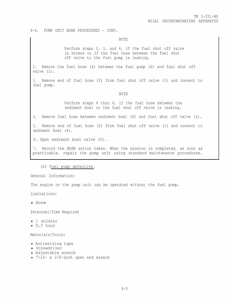
TM 3-251-BDM12A1 DECONTAMINATING APPARATUS
4-6. PUMP UNIT BDAR PROCEDURES - CONT.
NOTE
Perform steps 2, 3, and 6, if the fuel shut off valveis broken or if the fuel hose between the fuel shutoff valve to the fuel pump is leaking.
2. Remove the fuel hose (2) between the fuel pump (6) and fuel shut offvalve (l).
3. Remove end of fuel hose (3) from fuel shut off valve (1) and connect tofuel pump.
NOTE
Perform steps 4 thru 6, if the fuel hose between thesediment bowl or the fuel shut off valve is leaking.
4. Remove fuel hose between sediment bowl (4) and fuel shut off valve (l).
5. Remove end of fuel hose (2) from fuel shut off valve (1) and connect tosediment bowl (4).
6. Open sediment bowl valve (5).
7. Record the BDAR action taken. When the mission is completed, as soon aspracticable, repair the pump unit using standard maintenance procedures.
(2) Fuel pump defective.
General Information:
The engine on the pump unit can be operated without the fuel pump.
Limitations:
• None
Personnel/Time Required
• 1 soldier• 0.3 hour
Materials/Tools:
• Antiseizing tape• Screwdriver• Adjustable wrench• 7/16- x 3/8-inch open end wrench
4-5

TM 3-251-BDM12A1 DECONTAMINATING APPARATUS
4-6. PUMP UNIT BDAR PROCEDURES - CONT.
Procedural Steps:
1.
2.
Shut off sediment bowl valve (2).
Remove cover from the top of the engine.
3. Remove fuel line (4) and adapter (3) from carburetor.
4. Remove fuel hose (8) from adapter (7) on fuel pump.
5. Remove pipe nipple (5), 90° elbow (6), and adapter (7) from the fuel pump.
6. Wrap threads on pipe nipple (5) and adapter (7) with antiseizing tape (35,appx C).
7. Install pipe nipple (5), 90° elbow (6), and adapter (7) in carburetor.
8. Reconnect fuel hose (8) to adapter (7) on carburetor.
9. Install cover on top of the engine.
10. Open sediment bowl valve (2).
11. Record the BDAR action taken. When the mission is completed, as soon aspracticable, repair the pump unit using standard maintenance procedures.
4-6

TM 3-251-BDM12A1 DECONTAMINATING APPARATUS
4-6. PUMP UNIT BDAR PROCEDURES - CONT.
b. Indicator System Failures.
(1) Tachometer defective.
NOTE
The pump unit can be operated with a defective tachometer.The maximum RPM of the engine on the pump unit will belimited by the governor to protect the unit from damage.
(2) Pressure gage defective.
NOTE
The pump unit can be operated with a defective pressure gage.
(3) Vacuum gage defective.
NOTE
The pump unit can be operated with a defective vacuum gage.
(1) Pump drain valve defective.
General Information:
c. Pumping System Failures.
The pump unit can be operated with normal water pressure after the pipe cap isinstalled. In a freezing environment, remove pipe cap to drain pump after missionis completed.
Limitations:
• None
Personnel/Time Required:
• 1 soldier• 0.3 hour
Materials/Tools:
• l/2-inch pipe cap• Pipe wrenches• Antiseizing tape• Adjustable wrench
4-7

TM 3-251-BDM12A1 DECONTAMINATING APPARATUS
4-6. PUMP UNIT BDAR PROCEDURES - CONT.
Procedural Steps:
1. Disconnect handle extension (2) from valve (3).
2. Attempt to operate valve (3) by using a wrench on the valve stem. If valvedoes not function, proceed to step 3.
3. Remove defective valve (3) and adapter (4).
4. Wrap threads of nipple (1) with antiseizing tape (35, appx C) and install pipecap (5, appx C) on nipple.
5. Record the BDAR action taken. When the mission is completed, as soon aspracticable, repair the pump unit using standard maintenance procedures.
4-8

TM 3-251-BDM12A1 DECONTAMINATING APPARATUS
4-6. PUMP UNIT BDAR PROCEDURES - CONT.
(2) Vacuum hose defective.
General Information:
To detect small holes in the vacuum hose it may be necessary to manually fill thehose with water.
Limitations:
•This BDAR fix will not work on larger cuts, tears, or holes in the vacuum line,refer to the water hose BDAR fix for this type damage.
Personnel/Time Required:
• 1 soldier• 0.2 hour
Materials/Tools:
• Pressure sensitive tape
(3) Water hose defective.
General Information:
The water hose may not rewind properly on the hose reel after this BDAR fix.
4-9
Procedural Steps:
1. Wrap several layers of pressure sensitive tape (37, appx C) over top of thehole.
2. Record the BDAR action taken. When the mission is completed, as soon aspracticable, repair the pump unit using standard maintenance procedures.
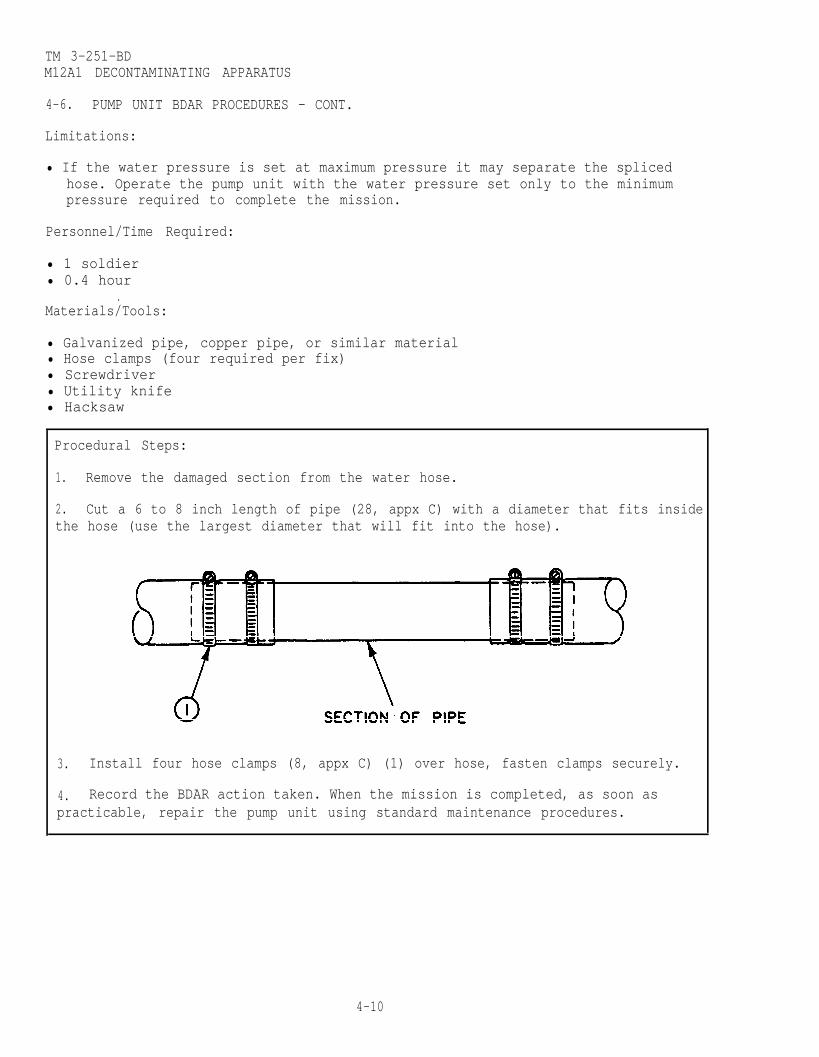
TM 3-251-BDM12A1 DECONTAMINATING APPARATUS
4-6. PUMP UNIT BDAR PROCEDURES - CONT.
Limitations:
• If the water pressure is set at maximum pressure it may separate the splicedhose. Operate the pump unit with the water pressure set only to the minimumpressure required to complete the mission.
Personnel/Time Required:
• 1 soldier• 0.4 hour
.Materials/Tools:
• Galvanized pipe, copper pipe, or similar material• Hose clamps (four required per fix)• Screwdriver• Utility knife• Hacksaw
Procedural Steps:
1. Remove the damaged section from the water hose.
2. Cut a 6 to 8 inch length of pipe (28, appx C) with a diameter that fits insidethe hose (use the largest diameter that will fit into the hose).
3. Install four hose clamps (8, appx C) (1) over hose, fasten clamps securely.
4. Record the BDAR action taken. When the mission is completed, as soon aspracticable, repair the pump unit using standard maintenance procedures.
4-10

TM 3-251-BDM12A1 DECONTAMINATING APPARATUS
4-6. PUMP UNIT BDAR PROCEDURES - CONT.
(4) Pump housing cracked.
General Information:
CAUTION
The pump housing can be brazed, however, care must betaken not to overheat bearing or seal areas of the housing.
Limitations:
• None
Personnel/Time Required:
• 2 soldiers• 0.5 hour
Materials/Tools:
• Oxygen/acetylene outfit
Procedural Steps:
1. Repair the pump housing with the oxygen/acetylene outfit, if it can be done inplace.
2. Record the BDAR action taken. When the mission is completed, as soon aspracticable, repair the pump unit using standard maintenance procedures.
4-11

TM 3-251-BDM12A1 DECONTAMINATING APPARATUS
4-6. PUMP UNIT BDAR PROCEDURES - CONT.
d. Electrical System Failures.
(1) Circuit breaker (CB1) defective.
General Information:
CAUTION
The circuit breaker can be bypassed with a 25 amp fuse.In the absence of a fuse, use regular wire. The use ofregular wire will eliminate the 25 amp safety factor.
Limitations:
• None
Personnel/Time Required:
• 1 soldier• 0.2 hour
Materials/Tools:
• 25 amp fuse• Soldering iron• Electrical wire (16 AWG or larger)• Solder
Procedural Steps:
1. Cut two pieces of electrical wire (43, appx C) 2 inches in length andremove l/2-inch of insulation from each end.
2. Solder an electrical wire to each end of a 25 amp fuse (17, appx C).
3. Solder the fuse or a straight piece of regular wire between the two wireterminals on the back of the circuit breaker.
4. Record the BDAR action taken. When the mission is completed, as soon aspracticable, repair the pump unit using standard maintenance procedures.
4-12

TM 3-251-BDM12A1 DECONTAMINATING APPARATUS
4-6. PUMP UNIT BDAR PROCEDURES - CONT.
(2) Electrical wire defective.
General Information:
Any broken electrical wire can be repaired by the following BDAR fix.
Limitations:
• None
Personnel/Time Required:
•1 soldier• 0.2 hour
Materials/Tools:
• Electrical tape• Pliers• Soldering iron• Solder
Procedural Steps:
1. Remove sufficient insulation from the broken wire ends to allow a minimum offour twists of the wire ends.
2. Twist the wire ends together a minimum of four turns.
3. Solder (34, appx C) the twisted wire ends, if possible.
4. Wrap electrical tape (36, appx C) around soldered wire ends.
5. Record the BDAR action taken. When the mission is completed, as soon aspracticable, repair the pump unit using standard maintenance procedures.
(3) Low oil pressure switch (S4) defective.
General Information:
The low oil pressure switch (S4) contacts must be closed before the battery willcharge. The contacts close at 20 psi.
Limitations:
• None
4-13

TM 3-251-BDM12A1 DECONTAMINATING APPARATUS
4-6. PUMP UNIT BDAR PROCEDURES - CONT.
Personnel/Time Required:
• 1 soldier• 0.2 hour
Materials/Tools:
• Screwdriver
Procedural Steps:
1. Remove cover from the top of the engine.
2. Remove either wire from the oil pressure switch (S4) and install on the sameterminal with the other wire.
FOR ENGINES MFGBEFORE JANUARY 1969
3. Replace engine cover.
4. Record the BDAR action taken. When the mission is completed, as soon aspracticable, repair the pump unit using standard maintenance procedures.
4-14

TM 3-251-BDM12A1 DECONTAMINATING APPARATUS
4-6. PUMP UNIT BDAR PROCEDURES - CONT.
(4) Low oil pressure switch (S3) defective.
General Information:CAUTION
The BDAR fix will eliminate the low oil pressure safetyshutdown of the engine. Monitor oil pressure on the oilpressure gage.
Limitations:
• None
Personnel/Time Required
• 1 soldier• 0.2 hour
Materials/Tools:
• Electrical tape• Screwdriver
Procedural Steps:
1. Remove cover from the top of the engine.
2. Remove the wire from the oil pressure switch (S3) that comes from connectorJ1 and wrap electrical tape (36, appx C) around wire end.
3.
4.
Replace engine cover.
Record the BDAR action taken. When the mission is completed, as soon aspracticable, repair the pump unit using standard maintenance procedures.
4-15

TM 3-251-BDM12A1 DECONTAMINATING APPARATUS
4-6. PUMP UNIT BDAR PROCEDURES - CONT.
SECTION III. WATER HEATER
4-7. GENERAL .
This section contains BDAR procedures applicable to the water heater.
a. Visually Inspect Damage Found On:-Electrical System . . . . . . . . . . Para. 4-8a-Fuel System . . . . . . . . . . . . . .Para. 4-8b
No Damage Apparent -Indicator System . . . . . . . . . . . Para. 4-8c
b. Attempt to Start Water Heater-Electrical System . . . . . . . . . . Para. 4-8a-Fuel System . . . . . . . . . . . . . . Para. 4-8b
Will Not Start
No Damage Apparent -Indicator System . . . . . . . . . . Para. 4-8c
c. Attempt to Operate Water Heater-Electrical System . . . . . . . . . . Para. 4-8a-Fuel System . . . . . . . . . . . . . . Para. 4-8b-Indicator System . . . . . . . . . . . Para. 4-8c
Damage Found On
No SignificantDamage and WaterHeater Works ok.
4-16

TM 3-251-BDM12A1 DECONTAMINATING APPARATUS
4-8. WATER HEATER BDAR PROCEDURES.NOTE
The water heater can be bypassed by obtaining animmersion heater from the field kitchen and placingit directly into the tank unit.
a. Electrical System Failures.
(1) Time delay relays (TD1, TD2) defective.
CAUTION
This BDAR fix will eliminate one of the safetydevices of the water heater.
General Information:
The water heater will not operate if the time delay relays are interchanged.
Limitations:
• None
Personnel/Time Required:
• 1 soldier• 0.2 hour
Materials/Tools:
• Electrical wire (solid), paper clip, or similar item
4-17

TM 3-251-BDM12A1 DECONTAMINATING APPARATUS
4-8. WATER HEATER BDAR PROCEDURES - CONT.
Procedural Steps:
1. Remove outer cover and control box cover.
2. Remove defective time delay relay from socket.
3. Bend wire ends (44, appx C) so they fit securely into the pin holes on thetime delay relay socket.
4. Insert the wire into pin holes 5 and 7 of the socket.
50 Record the BDAR action taken. When the mission is completed, as soon aspracticable, repair the water heater using standard maintenance procedures.
4-18

TM 3-251-BDM12A1 DECONTAMINATING APPARATUS
4-8. WATER HEATER BDAR PROCEDURES - CONT.
(2) Combustion air pressure switch (S3) defective.
General Information:
CAUTION
This BDAR fix will eliminate one of the safetydevices of the water heater.
Limitations:
• None
Personnel/Time Required:
• 1 soldier• 0.2 hour
Materials/Tools:
• Screwdriver
Procedural Steps:
1. Remove cover from the combustion air pressure switch (S3).
2. Remove either wire from the combustion air pressure switch (S3) and installon the same terminal as the other wire.
3. Replace cover on the combustion air pressure switch (S3).
4. Record the BDAR action taken. When the mission is completed, as soon aspracticable, repair the water heater using standard maintenance procedures.
4-19

TM 3-251-BDM12A1 DECONTAMINATING APPARATUS
4-8. WATER HEATER BDAR PROCEDURES - CONT.
(3) Temperature limit switch (S1) defective.
General Information:
WARNING
Monitor water temperature constantly and keepbelow 220°F (104°C). A possibility of explosionexists if the temperature exceeds 220°F (104°C).
CAUTION
This BDAR fix will eliminate one of the safetydevices of the water heater.
Limitations:
• None
Personnel/Time Required:
• 1 soldier• 0.2 hour
Materials/Tools:
• Electrical tape• Soldering iron• Solder• Utility knife• Pliers
Procedural Steps:
1. Cut both wires off temperature limit switch (S1).
2. Remove approximately 1 inch of insulation from wire ends.
4-20

TM 3-251-BDM12A1 DECONTAMINATING APPARATUS
4-8. WATER HEATER BDAR PROCEDURES - CONT.
3. Twist wire ends together.
4. Solder wire ends, if possible.
5. Wrap electrical tape (36, appx C) around soldered wire ends.
6. Record the BDAR action takes. When the mission is completed, as soon aspracticable, repair the water heater using standard maintenance procedures.
(4) Flame switch (S2) defective.
General Information:CAUTION
This BDAR fix will eliminate one of the safetydevices of the water heater.
Limitations:
• None
Personnel/Time Required:
• 1 soldier• 0.2 hour
Materials/Tools:
• Electrical wire (16 AWG or larger)• Electrical tape• Soldering iron• Solder
4-21
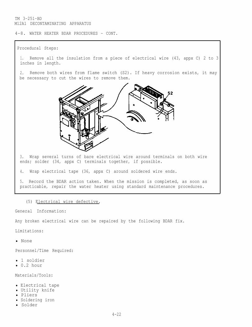
TM 3-251-BDM12A1 DECONTAMINATING APPARATUS
4-8. WATER HEATER BDAR PROCEDURES - CONT.
Procedural Steps:
1. Remove all the insulation from a piece of electrical wire (43, appx C) 2 to 3inches in length.
2. Remove both wires from flame switch (S2). If heavy corrosion exists, it maybe necessary to cut the wires to remove them.
3. Wrap several turns of bare electrical wire around terminals on both wireends; solder (34, appx C) terminals together, if possible.
4. Wrap electrical tape (36, appx C) around soldered wire ends.
5. Record the BDAR action taken. When the mission is completed, as soon aspracticable, repair the water heater using standard maintenance procedures.
(5) Electrical wire defective.
General Information:
Any broken electrical wire can be repaired by the following BDAR fix.
Limitations:
• None
Personnel/Time Required:
• 1 soldier• 0.2 hour
Materials/Tools:
• Electrical tape• Utility knife• Pliers• Soldering iron• Solder
4-22

TM 3-251-BDM12A1 DECONTAMINATING APPARATUS
4-8. WATER HEATER BDAR PROCEDURES - CONT.
Procedural Steps:
1. Remove sufficient insulation from the broken wire to allow a minimum of fourtwists of the ends.
3. Solder (34, appx C) the twisted wire ends, if possible.
4. Wrap electrical tape (36, appx C) around soldered wire ends.
5. Record the BDAR action taken. When the mission is completed, as soon aspracticable, repair the water heater using standard maintenance procedures.
b. Fuel System Failures.
Fuel hose defective.
General Information:
The water heater uses two fuel hoses; an inlet hose and a return hose.
Limitations:
• None
Personnel/Time Required:
• 1 soldier• 0.2 hour
Materials/Tools:
• Pressure sensitive tape• Hose clamps
4-23
2. Twist the wire ends a minimum of four turns.

TM 3-251-BDM12A1 DECONTAMINATING APPARATUS
4-8. WATER HEATER BDAR PROCEDURES - CONT.
Procedural Steps:
1. Wrap 3 to 4 layers of pressure sensitive tape (37, appx C) over hole in fuelhose.
2. Install two hose clamps (6, appx C) over tape (one on each side of hole) ortie with string, twine, or other suitable material.
3. Record the BDAR action taken. When the mission is completed, as soon aspracticable, repair the water heater using standard maintenance procedures.
c. Indicator System Failures.
Water pressure gage or water temperature gage defective.
General Information:
WARNING
When using the personnel shower, constantly monitor thewater heater output temperature to prevent burns topersonnel.
The water pressure gage or the water temperature gage are not required foroperation of the water heater.
4-24

4-9.
TM 3-251-BDM12A1 DECONTAMINATING APPARATUS
SECTION IV. TANK UNIT
GENERAL.
This section contains BDAR procedures applicable to the tank unit.
Visually Inspect Damage Found On:-Water Holding System . . . . . . . Para. 4-10
No Damage Apparent
Attempt to Fill Tank Will Not Hold Water:-Water Holding System . . . . . . . Para. 4-10
No Damage Apparent
No SignificantDamage and TankUnit Works ok.
4-10. TANK UNIT BDAR PROCEDURES.
Water Holding System Failures.
General Information:
The tank unit drain valve can be replaced with the valve from the pump unit orrepaired by the following BDAR fix.
Limitations:
• None
Personnel/Time Required:
• 2 soldiers• 0.5 hour
4-25
a.
b.
(1) Drain valve defective.
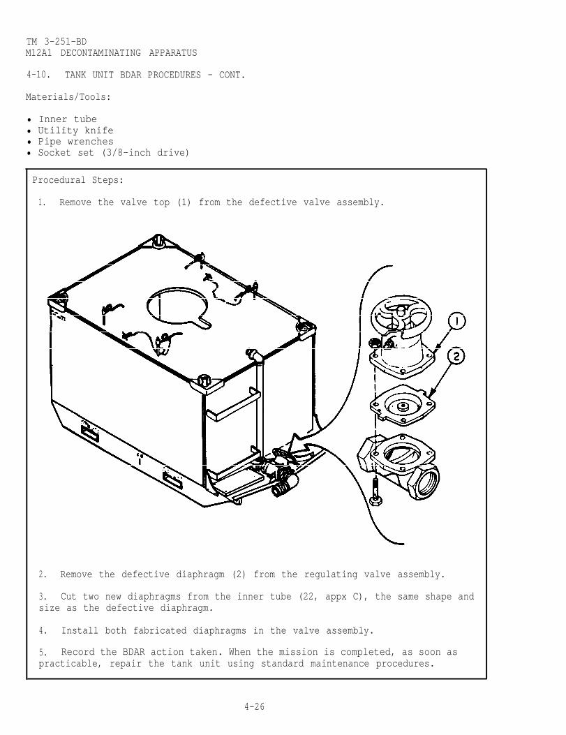
TM 3-251-BDM12A1 DECONTAMINATING APPARATUS
4-10. TANK UNIT BDAR PROCEDURES - CONT.
Materials/Tools:
• Inner tube• Utility knife• Pipe wrenches• Socket set (3/8-inch drive)
Procedural Steps:
1. Remove the valve top (1) from the defective valve assembly.
2. Remove the defective diaphragm (2) from the regulating valve assembly.
3. Cut two new diaphragms from the inner tube (22, appx C), the same shape andsize as the defective diaphragm.
4. Install both fabricated diaphragms in the valve assembly.
5. Record the BDAR action taken. When the mission is completed, as soon aspracticable, repair the tank unit using standard maintenance procedures.
4-26

TM 3-251-BDM12A1 DECONTAMINATING APPARATUS
4-10. TANK UNIT BDAR PROCEDURES - CONT.
(2) Water tank leaks.
General Information:
The water tank is made of stainless steel and can be welded.
Limitations:
• None
Personnel/Time Required:
• 2 soldiers• 0.5 hour
Materials/Tools:
• Oxygen/acetylene outfit• Flat steel
Procedural Steps:
1. Drain the water from the tank sufficiently below the hole or the crack toallow proper welding.
2. If the tank is cracked, weld the crack. If the tank has a hole in it, weldpiece of flat steel over the hole.
3. Record the BDAR action taken. When the mission is completed, as soon aspracticable, repair the tank unit using standard maintenance procedures.
4-27/(4-28 blank)

TM 3-251-BD
CHAPTER 5
Mll DECONTAMINATING APPARATUS
BDAR FIXES SHALL BE USED ONLY IN COMBATAT THE DISCRETION OF THE COMMANDER
AND SHALL BE REPAIRED BY STANDARD MAINTENANCE PROCEDURESAS SOON AS PRACTICABLE AFTER THE MISSION IS COMPLETED.
5-1. SCOPE.
This chapter contains BDAR procedures applicable to the M11 DecontaminatingApparatus.
SECTION I. INTRODUCTION
5-2. DESCRIPTION.
The Mll Decontaminating Apparatus is a hand held portable unit. The unit holds1-1/2 quarts (1.4 liters) of decontaminating agent (DS2) and will decontaminate anarea of approximately 135 square feet (12.5 square meters).
5-3. ASSESSMENT PROCEDURE.
a. Visually Inspect
No DamageApparent
No SignificantDamage andUnit Works ok.
5-4. REPAIR PROCEDURE INDEX.
Damage Observed on:-Mll DecontaminatingApparatus . . . . . . . . . . . . . . . Section II
Para.
Handle Broken . . . . . . . . . . . . . . . . . . . . . . . . . . . . . . . . . . . . . . . . . . . . 5-6aThumb Lever Missing . . . . . . . . . . . . . . . . . . . . . . . . . . . . . . . . . . . . . . . . . 5-6b
5-1
TM 3-251-BDMll DECONTAMINATING APPAMTUS
Section II. Mll DECONTAMINATING APPARATUS
5-5. GENERAL .
This section contains BDAR procedures applicable to the Mll DecontaminatingApparatus.
5-6. Mll DECONTAMINATING APPARATUS BDAR PROCEDURES.
a. Handle Failure.
General Information:
The handle is used to release nitrogen from the cylinder to pressurize thecontainer.
Limitations:
• This BDAR fix will not work if the handle is missing or too much of the handleis broken off.
Personnel/Time Required:
• 1 soldier• 0.1 hour
Materials/Tools:
• Screwdriver or similar tool
5-2

TM 3-251-BDMll DECONTAMINATING APPARATUS
5-6. Mll DECONTAMINATING APPARATUS BDAR PROCEDURES - CONT.
Procedural Steps:
1. Insert screwdriver under the handle.
2. Pry handle up until it locks in place.
3. Record the BDAR action taken. When the mission is completed, as soon aspracticable, repair the M11 Decontaminating Apparatus using standard maintenanceprocedures.
b. Thumb Lever Missing.]
General Information:
The thumb lever is used to release the DS2 from the container.
Limitations:
• None.
Personnel/Time Required:
• 1 soldier• 0.1 hour
Materials/Tools:
• None
5-3

TM 3-251-BDMll DECONTAMINATING APPARATUS
5-6. Ml1 DECONTAMINATING APPARATUS BDAR PROCEDURES - CONT.
Procedural Steps:
1. Press down on the valve stem with the thumb to release DS2 from thecontainer.
NOTE
If the valve stem cannot be pushed down withthe thumb, use a small stone or similar hardmaterial.
2. Record the BDAR action taken. When the mission is completed, as soon aspracticable, repair the Mll Decontaminating Apparatus using standard maintenanceprocedures.
5-4

TM 3-251-BD
CHAPTER 6
TYPE A/E32U-8 DECONTAMINATING APPARATUS
BDAR FIXES SHALL BE USED ONLY IN COMBATAT THE DISCRETION OF THE COMMANDER
AND SHALL BE REPAIRED BY STANDARD MAINTENANCE PROCEDURESAS SOON AS PRACTICABLE AFTER THE MISSION IS COMPLETED.
SECTION 1. INTRODUCTION
6-1. SCOPE.
This chapter describes BDAR procedures applicable to the TYPE A/E32U-8 Decontami-nating Apparatus
6-2. DESCRIPTION.
The TYPE A/E32U-8 Decontaminating Apparatus is a portable unit. It is operatedwithout external power. A two-cycle, air cooled engine drives the unit. Theapparatus can deliver water at various pressures and temperatures. The system canbe connected to provide personnel showers. It can also be used with cleaning wandsor siphon injector to decontaminate equipment.
6-3. ASSESSMENT PROCEDURE.
a. Visually Inspect Damage Observed on:-Engine . . . . . . . . . . . . . . . . Section II-Heat Exchanger . . . . . . . . . . . . . Section III
No Damage
b. Attempt to-Operate Will Not Operate:-Check Engine . . . . . . . . . . . . . . Section II-Check Heat Exchanger . . . . . . . . Section III
Operates
No SignificantDamage and UnitWorks ok.
6-1
Apparent

TM 3-251-BDTYPE A/E32U-8 DECONTAMINATING APPARATUS
6-4. REPAIR PROCEDURE INDEX. Para.
a. Engine
Electrical System Failures . . . . . . . . . . . . . . . . . . . . . . . . . 6-6aElectrical Wire DefectiveSpark Plug Defective
Fuel System Failures . . . . . . . . . . . . . . . . . . . . . . . . . . . 6-6bFuel Pump DefectiveFuel Hose Leaking
b. Heat Exchanger
Electrical System Failures. . . . . . . . . . . . . . . . . . . . . . . . . .6-8a45°C Thermostat S4 Defective120°C Thermostat S3 DefectiveThermostat Selector Switch (S2) Defective (120°C Switch Position)Thermostat Selector Switch (S2) Defective (No 120°C or 45°C
Selection, Desired Temperature 45°C)Thermostat Selector Switch (S2) Defective (No 120°C or 45°C
Selection, Desired Temperature 120°C)Electronic Control Module DefectiveHigh Pressure Switch (S5) DefectiveLow Pressure Switch (S6) DefectivePhotocell Assembly Defective
Fuel System Failures . . . . . . . . . . . . . . . . . . . . . . . . . . . . . 6-8bFuel Hose DefectiveHeater Fuel Filter Defective
Indicator System Failures. . . . . . . . . . . . . . . . . . . . . . . . . . . . . . 6-8CWATER TEMPERATURE Gage DefectiveWATER PRESSURE Gage Defective
Pumping System Failures.. . . . . . . . . . . . . . . . . . . . . . . . . . 6-8dHole in Heater CastingWater Hose Defective
6-2
TM 3-251-BDTYPE A/E32U-8 DECONTAMINATING APPARATUS
Section II. ENGINE
6-5. GENERAL.
This section contains BDAR procedures applicable to the engine.
a. Visually Inspect Damage Observed on:-Electrical System . . . . . . . . . . . . Para. 6-6a-Fuel System . . . . . . . . . . . . . . .Para. 6-6b
No DamageApparent
b. Attempt to Start Engine -Will Not Start:-Electrical System . . . . . . . . . . . . Para. 6-6a-Fuel System . . . . . . . . . . . . . . Para. 6-6b
No DamageApparent
No SignificantDamage and UnitWorks ok.
6-6. ENGINE BDAR PROCEDURES.
a. Electrical System Failures.
(1) Electrical wire defective.
General Information:
Any broken electrical wire can be repaired by the following BDAR fix.
Limitations:
• None
Personnel/Time Required
• 1 soldier• 0.2 hour
6-3
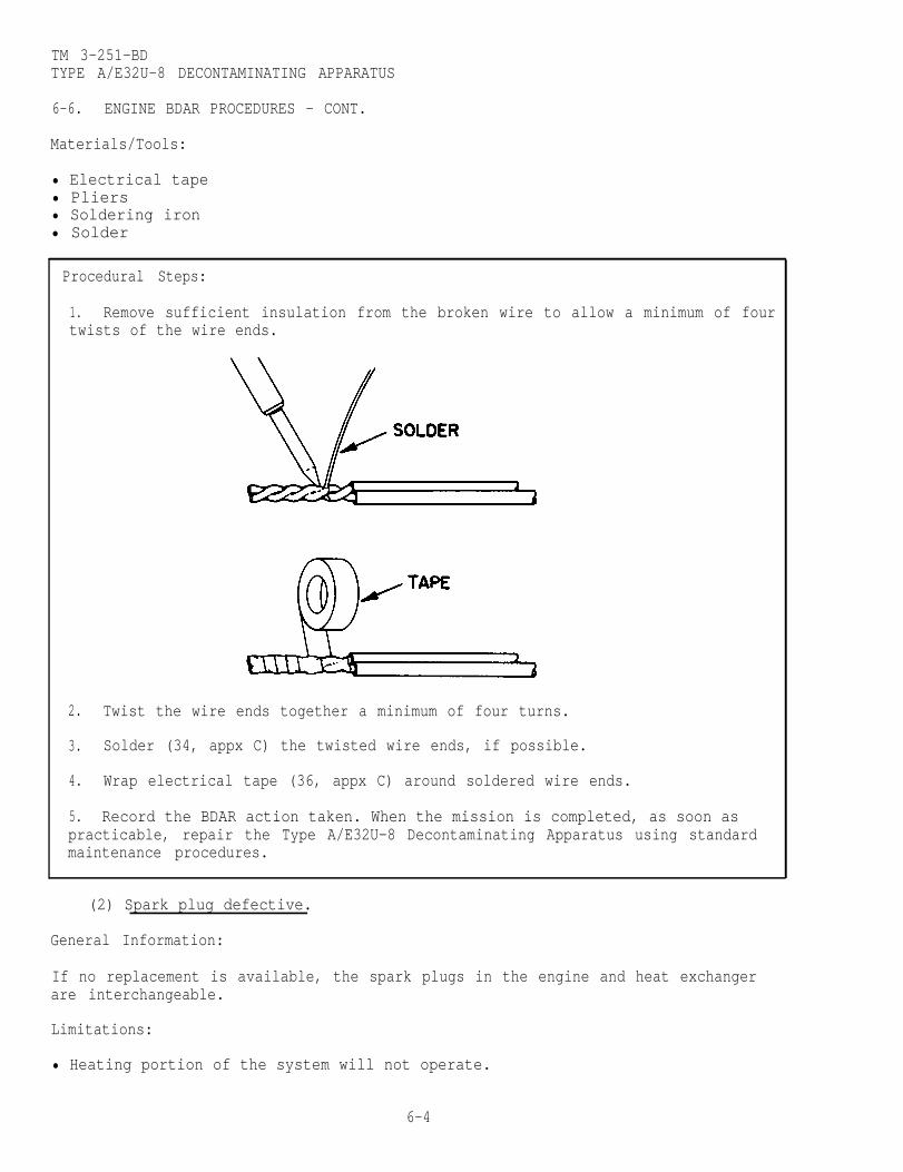
TM 3-251-BDTYPE A/E32U-8 DECONTAMINATING APPARATUS
6-6. ENGINE BDAR PROCEDURES - CONT.
Materials/Tools:
• Electrical tape• Pliers• Soldering iron• Solder
Procedural Steps:
1. Remove sufficient insulation from the broken wire to allow a minimum of fourtwists of the wire ends.
2. Twist the wire ends together a minimum of four turns.
3. Solder (34, appx C) the twisted wire ends, if possible.
4. Wrap electrical tape (36, appx C) around soldered wire ends.
5. Record the BDAR action taken. When the mission is completed, as soon aspracticable, repair the Type A/E32U-8 Decontaminating Apparatus using standardmaintenance procedures.
(2) Spark plug defective.
General Information:
If no replacement is available, the spark plugs in the engine and heat exchangerare interchangeable.
Limitations:
• Heating portion of the system will not operate.
6-4

TM 3-251-BDTYPE A/E32U-8 DECONTAMINATING APPARATUS
6-6. ENGINE BDAR PROCEDURES - CONT.
Personnel/Time Required:
• 1 soldier• 0.2 hour
Materials/Tools:
• Feeler gage• Spark plug wrench
Procedural Steps:
1. Remove spark plug from engine.
2. Remove spark plug from the heat exchanger.
3. Using feeler gage, re-gap the heat exchanger spark plug to 0.030 inch.
4. Install the spark plug in the engine.
5. Remove fuel pump drive belt.
6. Remove the heater fuel can.
7. Record the BDAR action taken. When the mission is completed, as soon aspracticable, repair the engine using standard maintenance procedures.
6-5

TM 3-251-BDTYPE A/E32U-8 DECONTAMINATING APPARATUS
6-6. ENGINE BDAR PROCEDURES - CONT.
b. Fuel System Failures.
(1) Engine fuel pump defective.
General Information:
Limitations:
• None
Personnel/Time Required
• 1 soldier• 0.2 hour
The engine can be operated without the fuel pump.
Materials/Tools:
• None
Procedural Steps:
1. Remove hose (1) (view A) from engine fuel pump (4).
2. Remove hose (2) from engine fuel pump (4) and carburetor (3).
3. Connect end of hose (1) (view B), removed in step 1, to carburetor (3).
4. Record the BDAR action taken. When the mission is completed, as soon aspracticable, repair the engine using standard maintenance procedures.
6-6

TM 3-251-BDTYPE A/E32U-8 DECONTAMINATING APPARATUS
6-6. ENGINE BDAR PROCEDURES - CONT.
6-7

TM 3-251-BDTYPE A/E32U-8 DECONTAMINATING APPARATUS
6-6. ENGINE BDAR PROCEDURES - CONT.
(2) Fuel hose leaking.
General Information:
The fuel hose can be repaired without affecting the operation of the engine.
Limitations:
• None
Personnel/Time Required:
• 1 soldier• 0.3 hour
Materials/Tools:
• Patch (from repair kit)• Sealant• Pressure sensitive tape• Solid wire (20 AWG or larger)
Procedural Steps:
1. Clean all dirt and grease from around the leak.
2. Coat the leaking area with sealant (33, appx C).
3. Wrap the hose with patching material.
4. Wrap the patched area with pressure sensitive tape (37, appx C).
5. Wrap wire (41, appx C) around the pressure sensitive tape as reinforcement.
6. Wrap an additional coating of pressure sensitive tape over the wire.
7. Record the BDAR action taken. When the mission is completed, as soon aspracticable, repair the engine using standard maintenance procedures.
6-8

TM 3-251-BDTYPE A/E32U-8 DECONTAMINATING APPARATUS
Section III. HEAT EXCHANGER
6-7. GENERAL .
This section contains BDAR procedures applicable to the heat exchanger.
a. Visually Inspect. Damage Observed on:-Electrical System . . . . . . . . . . . . . . Para. 6-8a-Fuel System . . . . . . . . . . . . . . . . . . Para. 6-8b-Indicator System . . . . . . . . . . . . . . . Para. 6-8c
No DamageApparent
b. Attempt to Start Heat Will Not Start:Exchanger -Electrical System . . . . . . . . . . . . . . Para. 6-8a
-Fuel System . . . . . . . . . . . . . . . . . . Para. 6-8b-Indicator System . . . . . . . . . . . . . . .Para. 6-8c
No DamageApparent
c. Attempt to Operate Heat Damage Found on:Exchanger -Electrical System . . . . . . . . . . . . . . .Para. 6-8a
-Fuel System . . . . . . . . . . . . . . . . . . Para. 6-8b-Indicator System . . . . . . . . . . . . . . .Para. 6-8c-Pumping System . . . . . . . . . . . . . . . . Para. 6-8d
No SignificantDamage and HeatExchanger UnitWorks ok.
6-9
TM 3-251-BDTYPE A/E32U-8 DECONTAMINATING APPARATUS
6-8. HEAT EXCHANGER BDAR PROCEDURES.
a. Electrical System Failures.
(1) 45°C thermostat (S4) defective.
General Information:
This BDAR fix will eliminate on of the safety devices, the45° C thermostat (S4). Be extremely careful during operation.Water temperature must be constantly monitored by trainedpersonnel to prevent serious burns or scalding.
NOTE
The 45°C thermostat (S4) can be bypassed by switching theTHERMOSTAT SELECTOR to the 120°C position and monitoringthe WATER TEMPERATURE gage to keep the water below 45°Con the gage. Pressure must be monitored to keep below 100psig.
(2) 120°C thermostat (S3) defective.
General Information:
WARNING
This BDAR fix will eliminate one of the safety devices ofthe heat exchanger, the 120°C thermostat. Explosion mayoccur if temperature is not constantly monitored.
NOTE
The 120°C thermostat (S3), can be bypassed without affectingthe operation of the heat exchanger. You must monitor theWATER TEMPERATURE gage to keep the water below 120°C onthe gage.
Limitations:
• None
Personnel/Time Required
• 1 soldier• 0.3 hour
Materials/Tools:
• Electrical wire (18 AWG or larger)• Screwdriver
6-10
WARNING

TM 3-251-BDTYPE A/E32U-8 DECONTAMINATING APPARATUS
6-8. HEAT EXCHANGER BDAR PROCEDURES - CONT.
Procedural Steps:
1. Remove the front panel (2) from the control panel (1) by removing the fourscrews (3).
2. Remove l/2-inch of insulation from both ends of a 6-inch length of wire (43,
3. Loosen the screw on terminal 1 of S2 that has a red wire marked 1.
appx C.)
4. Install one end of the jumper wire to terminal 1 and tighten the screw.
5. Loosen the screw on terminal 12 of the terminal board.
6. Install the other end of the jumper wire to terminal 12 and tighten thescrew.
7. Record the BDAR action taken. When the mission is completed, as soon aspracticable, repair the heat exchanger using standard maintenance procedures.
6-11

TM 3-251-BDTYPE A/E32U-8 DECONTAMINATING APPARATUS
6-8. HEAT EXCHANGER BDAR PROCEDURES - CONT.
(3) THERMOSTAT SELECTOR switch (S2) defective (120°C switch position).
General Information:
The 120°C position of the THERMOSTAT SELECTOR switch (S2) can be bypassed withoutaffecting the operation of the heat exchanger; however, the operation of the 45°Cthermostat is lost.
Limitations:
• None
Personnel/Time Required:
• 1 soldier• 0.2 hour
Materials/Tools:
• Screwdriver
Procedural Steps:
1. Remove the front panel (2) from the control panel (1) by removing four screws(3).
6-12

TM 3-251-BDTYPE A/E32U-8 DECONTAMINATING APPARATUS
6-8. HEAT EXCHANGER BDAR PROCEDURES - CONT.
2. Loosen the screw on terminal 1 of S2, disconnect red wire marked 1, andtighten the screw.
3. Loosen the screw on terminal 2 with the red and white/gray wires attached,connect the red wire marked 1 to terminal 2S and tighten the screw.
4. Record the BDAR action taken. When the mission is completed, as soon aspracticable, repair the heat exchanger using standard maintenance procedures.
(4) THERMOSTAT SELECTOR switch (S2) defective (No 120°C or 45°C selection,desired temperature 45°C).
General Information:
The 45°C mode of operation can be obtained by bypassing the THERMOSTAT SELECTORswitch (S2).
NOTE
Limitations:
• None
Personnel/Time Required:
• 1 soldier• 0.2 hour
Materials/Tools:
• Screwdriver
To shut off the heat exchanger, you must returnthe wire to its original position.
6-13

TM 3-251-BDTYPE A/E32U-8 DECONTAMINATING APPARATUS
6-8. HEAT EXCHANGER BDAR PROCEDURES - CONT.
Procedural Steps:
1. Remove the front panel (2) from control panel (1) by removing four screws(3).
2. Loosen the screw on terminal 2 of S2 with 1 white/gray wire attached, discon-nect the wire, and tighten the screw.
3. Loosen the screw on terminal 1 with two white/gray wires attached, connectthe white/gray wire removed in step 2 above, tighten the screw.
4. Record the BDAR action taken. When the mission is completed, as soon aspracticable, repair the heat exchanger using standard maintenance procedures.
6-14
TM 3-251-BDTYPE A/E32U-8 DECONTAMINATING APPARATUS
6-8. HEAT EXCHANGER BDAR PROCEDURES - CONT.
(5) THERMOSTAT SELECTOR switch (S2) defective (No 120°C or 45°C selection,desired temperature 120°C).
General Information:
The 120°C mode of operation can be obtained by bypassing the THERMOSTAT SELECTORswitch (S2),
NOTE
To shut off the heat exchanger, you must return thewire to its original position.
Limitations:
• None
Personnel/Time Required:
• 1 soldier• 0.2 hour
Materials/Tools:
• Screwdriver
6-15

TM 3-251-BDTYPE A/E32U-8 DECONTAMINATING APPARATUS
6-8. HEAT EXCHANGER BDAR PROCEDURES - CONT.
Procedural Steps:
1. Remove the front panel (2) from the control panel (1) by removing four screw(3).
2. Loosen the screw on terminal 1 of S2 with two red wires attached, disconnectthe red wire marked 1, and tighten the screw.
3. Loosen the screw on terminal 1 of S2 with two white/gray wires attached,install the red wire marked 1 removed in step 2 above, and tighten the screw.
4. Record the BDAR action taken. When the mission is completed, as soon aspracticable, repair the heat exchanger using standard maintenance procedures-
6-16

i6-8. HEAT EXCHANGER BDAR PROCEDURES - CONT.
TM 3-251-BDTYPE A/E32U-8 DECONTAMINATING APPARATUS
(6) Electronic control module defective. (Burner will ignite when STARTBURNER switch is depressed; however, it will go out when the switch is released.)
General Information:
The electronic control module can be bypassed without affecting the operation ofthe heat exchanger.
WARNING
This BDAR fix will eliminate the low and high water pressuresafety shutdown of the heat exchanger. Monitor the waterpressure on the water pressure gage. Keep the pressure below130 psig and above 22 psig.
Limitations:
• None
Personnel/Time Required:
• 1 soldier• 0.2 hour
Materials/Tools:
• Screwdriver
6-17

TM 3-251-BDTYPE A/E32U-8 DECONTAMINATING APPARATUS
6-8. HEAT EXCHANGER BDAR PROCEDURES - CONT.
Procedural Steps:
Do not pump fuel into heat exchanger for more than 2seconds. Heater flooding could occur and cause a fireor explosion. This could result in equipment damage orserious injury to personnel.
NOTE
To start heat exchanger with START BURNER switch bypassed,
1.(3).
turn THERMOSTAT SELECTOR switch to the 45° or 120°C positionfor not more than 2 seconds. To shut down the heat exchangers
Remove the front panel (2) from the control panel (1) by removing four screws
turn the switch to OFF.
WARNING
6-18

TM 3-251-BDTYPE A/E32U-8 DECONTAMINATING APPARATUS
6-8. HEAT EXCHANGER BDAR PROCEDURES - CONT.
2. Loosen the screw on terminal 3 of S1, disconnect the white/gray wire thatconnects V1 and S1 and tighten the screw.
3. Loosen the screw on terminal 4 of S1, install the white/gray wire removed instep 2 above and tighten the screw.
4. Record the BDAR action taken. When the mission is completed, as soon aspracticable, repair the heat exchanger using standard maintenance procedures.
(7) High pressure switch (S5) defective.
General Information:
WARNING
The high pressure switch (S5) can be bypassed. Bypassingthe switch eliminates the high pressure safety factor andcould cause a fire and/or explosion resulting in equipmentdamage or serious injury to personnel. Monitor the waterpressure on the WATER PRESSURE gage and keep it below 130psig.
Limitations:
• None
Personnel/Time Required:
• 1 soldier• 0.2 hour
Materials/Tools:
• Screwdriver
6-19

TM 3-251-BDTYPE A/E32U-8 DECONTAMINATING APPARATUS
6-8. HEAT EXCHANGER BDAR PROCEDURES - CONT.
Procedural Steps:
1. Remove the front panel (2) from the control panel (1) by removing fourscrews (3).
2. Loosen the screw on terminal 10 of the terminal board, remove the white wire,and tighten the screw.
3. Loosen the screw on terminal 9, install the white wire removed in step 2above, and tighten the screw.
4. Record the BDAR action taken. When the mission is completed, as soon aspracticable, repair the heat exchanger using standard maintenance procedures.
6-20

6-8. HEAT EXCHANGER BDAR PROCEDURES - CONT.
(8) Low pressure switch (S6) defective.
General Information:
CAUTION
The low pressure switch (S6) can be bypassed. Bypassing the
above 22 psig.
Limitations:
• None
Personnel/Time Required:
• 1 soldier• 0.2 hour
Materials/Tools:
• Screwdriver
TM 3-251-BDTYPE A/E32U-8 DECONTAMINATING APPARATUS
switch eliminate the low pressure safety factor; monitorthe water pressure on the WATER PRESSURE gage and keep it
6-21
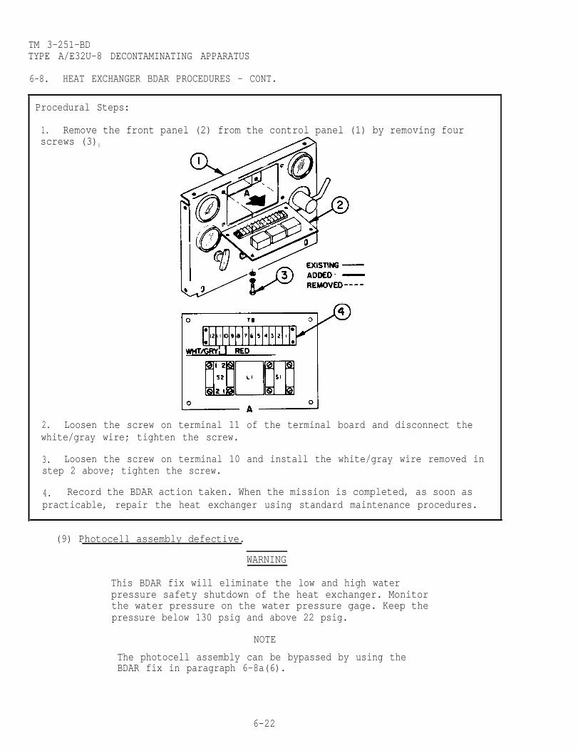
TM 3-251-BDTYPE A/E32U-8 DECONTAMINATING APPARATUS
6-8. HEAT EXCHANGER BDAR PROCEDURES - CONT.
Procedural Steps:
1. Remove the front panel (2) from the control panel (1) by removing fourscrews (3)0
2. Loosen the screw on terminal 11 of the terminal board and disconnect thewhite/gray wire; tighten the screw.
3. Loosen the screw on terminal 10 and install the white/gray wire removed instep 2 above; tighten the screw.
4. Record the BDAR action taken. When the mission is completed, as soon aspracticable, repair the heat exchanger using standard maintenance procedures.
(9) Photocell assembly defective.
WARNING
This BDAR fix will eliminate the low and high waterpressure safety shutdown of the heat exchanger. Monitorthe water pressure on the water pressure gage. Keep thepressure below 130 psig and above 22 psig.
NOTE
The photocell assembly can be bypassed by using theBDAR fix in paragraph 6-8a(6).
6-22
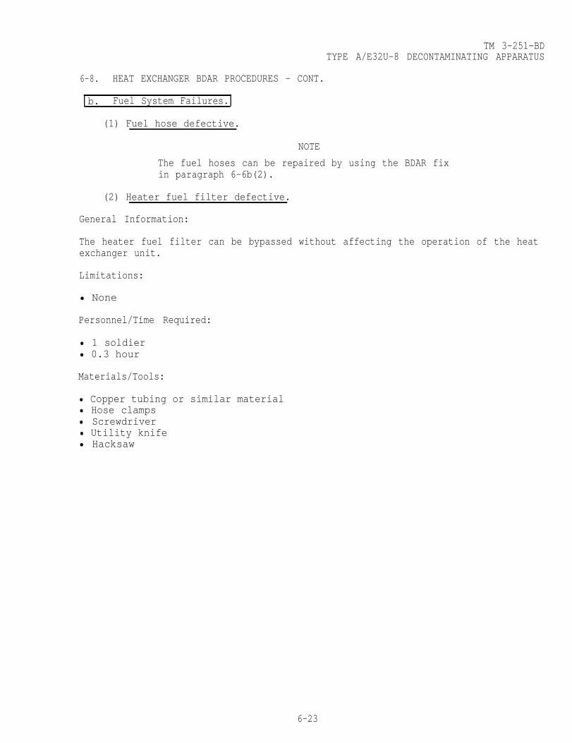
TM 3-251-BDTYPE A/E32U-8 DECONTAMINATING APPARATUS
6-8. HEAT EXCHANGER BDAR PROCEDURES - CONT.
b. Fuel System Failures.
(1) Fuel hose defective.
NOTE
The fuel hoses can be repaired by using the BDAR fixin paragraph 6-6b(2).
(2) Heater fuel filter defective.
General Information:
The heater fuel filter can be bypassed without affecting the operation of the heatexchanger unit.
Limitations:
• None
Personnel/Time Required:
• 1 soldier• 0.3 hour
Materials/Tools:
• Copper tubing or similar material• Hose clamps• Screwdriver• Utility knife• Hacksaw
6-23
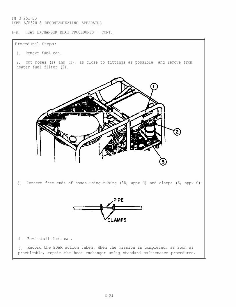
TM 3-251-BDTYPE A/E32U-8 DECONTAMINATING APPARATUS
6-8. HEAT EXCHANGER BDAR PROCEDURES - CONT.
Procedural Steps:
1. Remove fuel can.
2. Cut hoses (1) and (3), as close to fittings as possible, and remove fromheater fuel filter (2).
3.
4.
5.
Connect free ends of hoses using tubing (38, appx C) and clamps (6, appx C).
Re-install fuel can.
Record the BDAR action taken. When the mission is completed, as soon as.practicable, repair the heat exchanger using standard maintenance procedures.
6-24

TM 3-251-BDTYPE A/E32U-8 DECONTAMINATING APPARATUS
6-8. HEAT EXCHANGER BDAR PROCEDURES - CONT.
c. Indicator System Failures.
(1) WATER TEMPERATURE gage defective.
NOTE
The heat exchanger can be operated with a defective WATERTEMPERATURE gage. The 120°C thermostat (S3) and 45°Cthermostat (S4) will limit the water temperature.
NOTE
The heat exchanger can be operated with a defective WATERPRESSURE gage. The high and low pressure switches willprotect the unit from damage.
d. Pumping System Failures.
(1) Hole in heater casting.
NOTE
The heat exchanger can be operated with a hole in thecasting, provided the heater coil is not leaking.
(2) Water hose defective.
General Information:
The water hose can be repaired without affecting the operation of the heatexchanger.
Limitations:
• If the water pressure is set at maximum pressure, the spliced hose mayseparate. Operate the pumping system with the water pressure set to theminimum pressure required to complete the mission.
Personnel/Time Required:
• 1 soldier• 0.4 hour
Materials/Tools
• Galvanized pipe, copper pipe, or similar material• Hose clamps• Screwdriver• Utility knife• Hacksaw
6-25
(2) WATER PRESSURE gage defective.
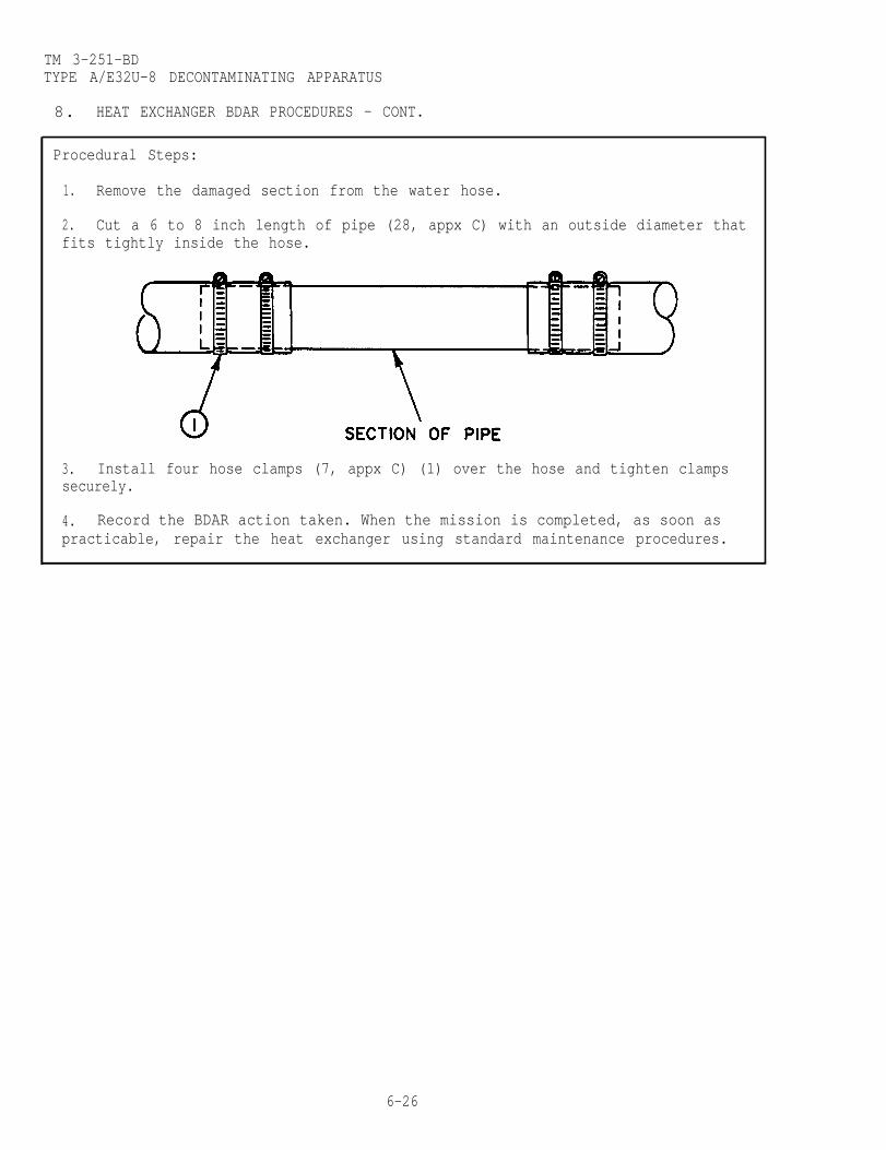
TM 3-251-BDTYPE A/E32U-8 DECONTAMINATING APPARATUS
8. HEAT EXCHANGER BDAR PROCEDURES - CONT.
Procedural Steps:
1. Remove the damaged section from the water hose.
2. Cut a 6 to 8 inch length of pipe (28, appx C) with an outside diameter thatfits tightly inside the hose.
3. Install four hose clamps (7, appx C) (1) over the hose and tighten clampssecurely.
4. Record the BDAR action taken. When the mission is completed, as soon aspracticable, repair the heat exchanger using standard maintenance procedures.
6-26

TM 3-251-BD
CHAPTER 7
M13 DECONTAMINATING APPARATUS
BDAR FIXES SHALL BE USED ONLY IN COMBATAT THE DISCRETION OF THE COMMANDER
AND SHALL BE REPAIRED BY STANDARD MAINTENANCE PROCEDURESAS SOON AS PRACTICABLE AFTER THE MISSION IS COMPLETED.
SECTION I. INTRODUCTION
7-1. SCOPE.
This chapter describes BDAR procedures applicable to the M13 DecontaminatingApparatus.
7-2. DESCRIPTION.
The M13 Decontaminating Apparatus is a one man portable unit. The unit holds 14liters (3.7 gallons) of decontaminating agent (DS2) and will decontaminate an areaof approximately 111.5 square meters (1200 square feet).
7-3. ASSESSMENT PROCEDURE.
a. Visually Inspect Damage Observed on:
No DamageApparent
-M13 DecontaminatingApparatus . . . . . . . . . . . . . Section II
b. Attempt to Operate Will Not Operate:-M13 DecontaminatingApparatus . . . . . . . . . . . . . Section II
Operates
No SignificantDamage and UnitWorks ok.
7-1

TM 3-251-BDM13 DECONTAMINATING APPARATUS
7-4. REPAIR PROCEDURE INDEX. Para.
Hose Cut . . . . . . . . . . . . . . . . . . . . . . . . . . . . . . . . . . . . . . . 7-6aWands Leaking at Connectors. . . . . . . . . . . . . . . . . . . . . . . . . . 7-6bDecontamination Unit Becomes Inoperative . . . . . . . . . . . . . . . . 7-6c
Section II. M13 DECONTAMINATING APPARATUS
7-5. GENERAL .
This section contains BDAR procedures applicable to the M13 DecontaminatingApparatus.
7-6. M13 DECONTAMINATING APPARATUS BDAR PROCEDURES.
General Information:
The hose is used to transfer the DS2 from the fluid container to the cleaningbrush.
WARNING
Wear proper protective clothing when using DS2,which may cause severe burns to exposed skinand eyes.
Limitations:
• None
Personnel/Time Required:
• 1 soldier• 0.4 hour
Materials/Tools:
• Pressure sensitive tape• Metal tube (outside diameter of tube same as inside diameter of hose)• Hose clamps
7-2
a. Hose Cut

TM 3-251-BDM13 DECONTAMINATING APPARATUS
7-6. M13 DECONTAMINATING APPARATUS BDAR PROCEDURES - CONT.
Procedural Steps:
1. Cover hole with pressure sensitive tape (37, appx C).
2. If hole is too large, cut out damaged section of hose. Clean loose particlesfrom hose.
3. Cut tightly fitting metal tube (26, appx C) to proper length.
4. Install metal tube inside cut ends of damaged hose.
5. Secure with hose clamps (6, appx C).
6. Record the BDAR action taken. When the mission is completed, as soon aspracticable, repair the M13 Decontaminating Apparatus using standard maintenanceprocedures.
b. Wands Leaking at Connectors.
General Information:
The wands are threaded together. The sections are sealed by O-rings in theconnectors.
Limitations:
• None
Personnel/Time Required:
• 1 soldier• 0.2 hour
Materials/Tools:
• Sealing compound• Pressure sensitive tape
7-3

TM 3-251-BDM13 DECONTAMINATING APPARATUS
7-6. M13 DECONTAMINATING APPARATUS BDAR PROCEDURES - CONT.
Procedural Steps:
1. Separate wand connectors and apply sealing compound (31, appx C) to thethreads.
2. Screw connectors together.
3. Wrap connectors with pressure sensitive tape (37, appx C).
4. Record the BDAR action taken when the mission is completed, as soon aspracticable, repair the M13 Decontaminating Apparatus using standard maintenanceprocedures.
c. Decontamination Unit Becomes Inoperative.
General Information:
Wear proper protective clothing when using DS2, whichmay cause severe burns to exposed skin and eyes.
Decontamination can be continued by disassembling the M13 and applying DS2manually.
Limitations:
• The use life of DS2 is approximately 48 hours when exposed to air.
Personnel/Time Required:
• 1 soldier• 0.1 hour
7-4
WARNING

TM 3-251-BDM13 DECONTAMINATING APPARATUS
7-6. M13 DECONTAMINATING APPARATUS BDAR PROCEDURES - CONT.
Materials/Tools:
• Push broom or brush• Combination wrench 11/16-inch
Procedural Steps:
1. Disconnect hose from container and the wand.
2. Remove the quick connect plug from the fluid container.
3. Pour DS2 onto unit being decontaminated.
4. Use the M13 brush or push broom type brush to scrub unit beingdecontaminated.
5. Whenever possible, rinse unit with water after scrubbing with DS2.
6. Record the BDAR action taken. When the mission is completed, as soon aspracticable, repair the M13 Decontaminating Apparatus using standard maintenanceprocedures.
7-5/(7-6 blank)

TM 3-251-BD
CHAPTER 8
M3A4 SMOKE GENERATOR
BDAR FIXES SHALL BE USED ONLY IN COMBATAT THE DISCRETION OF THE COMMANDER
AND SHALL BE REPAIRED BY STANDARD MAINTENANCE PROCEDURESAS SOON AS PRACTICABLE AFTER THE MISSION IS COMPLETED.
SECTION I. INTRODUCTION
8-1. SCOPE .
This chapter describes BDAR procedures applicable to the M3A4 Smoke Generator.
8-2. DESCRIPTION.
The M3A4 Smoke Generator is a self-contained unit using a pulse-jet engine togenerate large area smoke screens that will reduce direct visual observation andconceal troops, vehicles, or installations from enemy view.
NOTE
If the M3A4 Smoke Generator cannot be repaired using aBDAR fix, combine parts from other damaged units to makean M3A4 Smoke Generator operational.
8-3. ASSESSMENT PROCEDURE.
a. Visually Inspect Damage Observed on:-M3A4 Smoke Generator . . . . . . Section II
Fuel System Failures . . . . . . . Para. 8-6aIndicator System Failures. . Para. 8-6bFog Oil System Failures . . . . Para. 8-6c
No Damage Air Pressure SystemApparent Failures . . . . . . . . . . . .Para. 8-6d
Ignition Magneto Failure. . . Para. 8-6e
b. Attempt to Operate Will Not Operate:-M3A4 Smoke Generator . . . . . . . . . Section II
Fuel System Failures . . . . . . . Para. 8-6aIndicator System Failures. . . . . .Para. 8-6bFog Oil System Failures . . . . Para. 8-6c
Operates Air Pressure SystemFailure . . . . . . . . . . . . .Para. 8-6d
Ignition Magneto Failure. . . Para. 8-6e
No SignificantDamage and UnitWorks ok.
8-1
TM 3-251-BDM3A4 SMOKE GENERATOR
8-4. REPAIR PROCEDURE INDEX. Para.
M3A4 Smoke Generator
Fuel System Failures . . . . . . . . . . . . . . . . . . . . . . . . . . . . . . . . . 8-6aFuel Tank LeakingFuel Filter Bowl Leaking or BrokenFuel Shut Off Valve Handle BrokenCarburetor Reservoir Toggle Valve Handle Broken
Indicator System Failures. . . . . . . . . . . . . . . . . . . . . . . . . .8-6bFuel Tank Gage DefectiveAir Pressure Gage Defective
Fog Oil System Failures... . . . . . . . . . . . . . . . . . . . . . . . . 8-6cFog Oil Line from Fog Oil Pump to Engine DefectiveFog Oil Inlet or Fog Oil Exhaust Hose DefectiveFog Oil Pump Drain Cock Broken Off
Air Pressure System Failures . . . . . . . . . . . . . . . . . . . . . . . . .8-6dAir Pump Mounting Brackets Broken
Ignition Magneto Failure . . . . . . . . . . . . . . . . . . . . . . . . . . . . 8-6e
8-2

8-5.
TM 3-251-BDM3A4 SMOKE GENERATOR
Section II. M3A4 SMOKE GENERATOR
This section contains BDAR procedures applicable to the M3A4 Smoke Generator.
8-6. M3A4 SMOKE GENERATOR BDAR PROCEDURES.
a. Fuel System Failures.
(1) Fuel tank leaking.
General Information:
If the fuel tank is leaking, it may be repaired until a replacement can beinstalled.
WARNING
The M3A4 Smoke Generator is extremely hot while operating.Any leakage could result in a destructive fire causingserious burns to personnel.
Limitations:
• None
Personnel/Time Required:
• 1 soldier• 1.5 hours
Materials/Tools:
• Adhesive sealant
8-3
GENERAL.

TM 3-251-BDM3A4 SMOKE GENERATOR
8-6. M3A4 SMOKE GENERATOR BDAR PROCEDURES - CONT.
Procedural Steps:
1. Remove fuel tank, if required.
2. Clean area around holes or cracks and fill with adhesive sealant (2, appx C),Permatex II, or any metal filler available.
3. If hole is too large to be filled, make a wooden peg and cover outside of pegwith sealer and place in hole.
4. Record the BDAR action taken. When the mission is completed, as soon aspracticable, repair the M3A4 Smoke Generator using standard maintenance procedures.
8-4

TM 3-251-BDM3A4 SMOKE GENERATOR
8-6. M3A4 SMOKE GENERATOR BDAR PROCEDURES - CONT.
(2) Fuel filter bowl leaking or broken.
General Information:
If the fuel filter bowl is leaking and no replacement is available, it can bebypassed.
Limitations:
• None
Personnel/Time Required:
• 1 soldier• 0.5 hour
Materials/Tools:
• Open end wrench 7/16-inch (2 required)• Open end wrench 9/16-inch• Open end wrench 5/8-inch• Screwdriver
Procedural Steps:
1. Turn off fuel shut off valve.
2. Disconnect fuel hose (1) from elbow (2) on carburetor.
8-5

TM 3-251-BDM3A4 SMOKE GENERATOR
8-6. M3A4 SMOKE GENERATOR BDAR PROCEDURES - CONT.
3. Remove screw from clamp (3) (view A), securing the fuel hose.
4. Disconnect bushing (4) with fuel line attached, from fuel filterassembly (5).
5. Swing fuel filter assembly away from main frame of smoke generator.
6. Remove pipe nipple (6), with fuel filter assembly (5) attached, fromsediment strainer (7).
7. Connect bushing (4) with fuel line attached to sediment strainer (7) andswing assembly to original position (view B).
8. Reinstall clamp removed in step 3, on fuel hose.
9. Reconnect fuel hose to elbow on carburetor that was disconnected in step 2above.
10. Record the BDAR action taken. When the mission is completed, as soon aspracticable, repair the M3A4 Smoke Generator using standard maintenanceprocedures.
8-6

TM 3-251-BDM3A4 SMOKE GENERATOR
8-6. M3A4 SMOKE GENERATOR BDAR PROCEDURES - CONT.
(3) Fuel shut off valve handle broken.
General Information:
The fuel shut off valve can be operated with a pair of pliers
Limitations:
• None
Personnel/Time Required:
• 1 soldier• 0.1 hour
Materials/Tools:
• Pliers
Procedural Steps:
1. Use pliers to turn remaining part of broken valve handle.
2. Place valve handle in the desired position.
3. Record the BDAR action taken. When the mission is completed, as soon aspracticable, repair the M3A4 Smoke Generator using standard maintenanceprocedures.
8-7
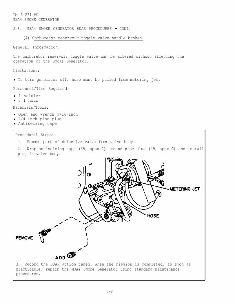
TM 3-251-BDM3A4 SMOKE GENERATOR
8-6. M3A4 SMOKE GENERATOR BDAR PROCEDURES - CONT.
(4) Carburetor reservoir toggle valve handle broken.
General Information:
The carburetor reservoir toggle valve can be altered without affecting theoperation of the Smoke Generator.
Limitations:
• To turn generator off, hose must be pulled from metering jet.
Personnel/Time Required:
• 1 soldier• 0.1 hour
Materials/Tools:
• Open end wrench 9/16-inch• l/4-inch pipe plug• Antiseizing tape
Procedural Steps:
1. Remove part of defective valve from valve body.
2. Wrap antiseizing tape (35, appx C) around pipe plug (29, appx C) and installplug in valve body.
3. Record the BDAR action taken. When the mission is completed, as soon aspracticable, repair the M3A4 Smoke Generator using standard maintenanceprocedures.
8-8

TM 3-251-BDM3A4 SMOKE GENERATOR
8-6 l M3A4 SMOKE GENERATOR BDAR PROCEDURES - CONT.
b. Indicator System Failures.
(1) Fuel tank gage defective,
NOTE
The M3A4 Smoke Generator can be operated with adefective fuel gage.
(2) Air pressure gage defective.
NOTE
The M3A4 Smoke Generator can be operated with adefective air pressure gage.
(1) Fog oil line from fog oil pump to engine defective.
General Information:
The fog oil line can be repaired.
Limitations:
• None
Personnel/Time Required:
• 1 soldier• 1.0 hour
Materials/Tools:
• Rubber hose (inside diameter of hose same as outside diameter of fog oil line)• Hose clamps• Sealing compound
c. Fog Oil System Failures.
Procedural Steps:
1. Cut out the damaged section of line.
2. Cut proper length of correct diameter rubber hose (21, appx C).
3. Spread a light coat of sealing compound (31, appx C) inside of hose ends.
4. Position hose over ends of line and secure in place with two or more hoseclamps (6, appx C).
5. Record the BDAR action taken. When the mission is completed, as soon aspracticable, repair the M3A4 Smoke Generator using standard maintenanceprocedures.
8-9

TM 3-251-BDM3A4 SMOKE GENERATOR
8-6. M3A4 SMOKE GENERATOR BDAR PROCEDURES - CONT.
(2) Fog oil inlet or fog oil exhaust hose defective.
General Information:
The fog oil hoses can be repaired.
Limitations:
• None
Personnel/Time Required:
• 1 soldier• 1.0 hour
Materials/Tools:
• Metal tube (outside diameter of tube same as inside diameter of hose)• Hose clamps
Procedural Steps:
1. Cut out damaged section of hose. Clean loose particles from cut ends ofhose.
2. Cut tightly fitting metal tube (26, appx C) to proper length.
4. Secure with two or more hose clamps (6, appx C).
5. Record the BDAR action taken. When the mission is completed, as soon aspracticable, repair the M3A4 Smoke Generator using standard maintenanceprocedures.
(3) Fog oil pump drain broken off.
General Information:
The drain cock hole can be plugged with a bolt or screw.
Limitations:
• None
Personnel/Time Required:
• 1 soldier• 0.3 hour
Material/Tools:
• Screw or bolt• Screwdriver or adjustable wrench
8-10
3. Install metal tube inside cut ends of damaged hose.

TM 3-251-BDM3A4 SMOKE GENERATOR
8-6. M3A4 SMOKE GENERATOR BDAR PROCEDURES - CONT.
Procedural Steps:
1. Remove remaining part of broken drain cock.
2. Install a screw or bolt with the same size threads as drain cock.
3. Record the BDAR action taken. When the mission is completed, as soon aspracticable, repair the M3A4 Smoke Generator using standard maintenanceprocedures.
d. Air Pressure System Failure.
Air pump mounting brackets broken.
General Information:
Mounting brackets can break due to vibration or rough handling.
Limitations:
• None
Personnel/Time Required:
• 1 soldier• 1.0 hour
Materials/Tools:
• Welding equipment• Solid wire or rope
8-11

TM 3-251-BDM3A4 SMOKE GENERATOR
8-6. M3A4 SMOKE GENERATOR BDAR PROCEDURES - CONT.
Procedural Steps:
1. If the bracket is broken at the base metal, reweld in place. Mounting holesmay be elongated to compensate for misalignment.
2. If bracket cannot be welded, tie the pump in place using rope (30, appx C) orwire.
3. Record the BDAR action taken. When the mission is completed, as soon aspracticable, repair the M3A4 Smoke Generator using standard maintenanceprocedures.
The M3A4 Smoke Generator contact set (points) is interchangeable with the contactset (points) from the M2 heater of the M12A1 Decontaminating Apparatus.
8-12
e. Ignition Magneto Failure.

TM 3-251-BD
CHAPTER 9
GAS-PARTICULATE FILTER UNITS: M7A1,M8A2, M8A3, M13, M13A1, and M14
BDAR FIXES SHALL BE USED ONLY IN COMBATAT THE DISCRETION OF THE COMMANDER
AND SHALL BE REPAIRED BY STANDARD MAINTENANCE PROCEDURESAS SOON AS PRACTICABLE AFTER THE MISSION IS COMPLETED.
SECTION I. INTRODUCTION
9-1. SCOPE .
This chapter contains BDAR procedures applicable to the Gas-Particulate FilterUnits M7A1, M8A2, M8A3, M13, M13A1 and M14.
9-2. DESCRIPTION.
The Gas-Particulate Filter Units provide NBC protection to hospital patients,armored ambulance patients, and combat vehicle personnel.
9-3. ASSESSMENT PROCEDURE.
a. Visually Inspect Damage Observed on:-Gas-ParticulateFilter Unit . . . . . . . . . . . . . . . . Section II
No DamageApparent
b. Attempt to Operate Will Not Operate:-Gas-ParticulateFilter Unit . . . . . . . . . . . . . . . . Section II
Operates
No SignificantDamage andUnit Works ok.
9-1

TM 3-251-BDGAS-PARTICULATE FILTER UNITS
9-4. REPAIR PROCEDURE INDEX. Para.
Headpiece Torn or Punctured (M7A1 and M14) . . . . . . . . . . . . . . . . . . . . . . .Eyepiece Punctured (M7A1 and M14) . . . . . . . . .. . . . . . .. . . . . . . . .Headpiece Strap Assembly Missing (M7A1 and M14) . . . . . . . . . . . . . . . . . . Ratchet Clamp Broken or Missing (M7A1, M8A2, M8A3, M13, M13A1,
and M14) . . . . . . . . . . . . . . . . . . . . . . . .. . . .Airduct Hose Punctured (Small Holes) (M7A1, M8A2, M8A3 M13, M13A1,
and M14) . . . . . . . . . . . . . . . . . . . . . . . . . . . . . . . . . . .Airduct Hose Punctured (Large Holes) or Cut (M7A1, M8A2, M8A3, M13,
M13A1, and M14) . . .. . . . . . . . . . . . . . . . . . . . . . . . . . . Quick Disconnect Coupling "O" Ring Missing (M7A1, M8A2, M8A3, M13)
M13A1, and M14) .. . . . . . . . . . . . . . . . . . . . . . . . . . . . . . . . . . . . .Electrical Wire Defective (M7A1, M8A2, M8A3, M13, M13A1, and M14) . . . . . .Circuit Breaker Defective (M8A2, M8A3, M13, M13A1, and M14) . . . . . . . . .ON/OFF Switch Defective (M7A1) . . . . . . . . . . . . . .. . . . . . . . . . . . . . . .
9-6a9-6b9-6c
9-6d
9-6e
9-6f
9-6g9-6h9-6i9-6j
SECTION II. GAS-PARTICULATE FILTER UNITS: M7A1,M8A2, M8A3, M13, M13A1, AND M14
9-5. GENERAL .
This section contains BDAR procedures applicable to the Gas-Particulate FilterUnits M7A1, M8A2, M8A3, M13, M13A1, and M14.
9-6. GAS-PARTICULATE FILTER UNIT BDAR PROCEDURES.
NOTE
Each BDAR fix pertains only to the model of theGas-Particulate Filter Units listed in parenthesis.
a. Headpiece Torn or Punctured (M7A1 and M14).
General Information:
The tom area of the headpiece must be completely free of foreign matter in orderto perform this BDAR fix.
Limitations:
• Moisture may need to be removed for this procedure to be effective
Personnel/Time Required:
• 1 soldier• 0.1 hour
Materials/Tools:
• Pressure sensitive tape
9-2

TM 3-251-BDGAS-PARTICULATE FILTER UNITS
9-6. GAS-PARTICULATE FILTER UNIT BDAR PROCEDURES - CONT.
Procedural Steps:
1. Wipe all dirt, grease, and foreign matter from the torn area on theheadpiece.
2. Cut a piece of pressure sensitive tape (37, appx C) 2 inches longer than thetear in the headpiece.
3. Center the pressure sensitive tape over the tear in the headpiece and pressfirmly in place.
4. Repeat steps 1 thru 3 on the other side of tear.
5. Record the BDAR action taken. when the mission is completed, as soon aspracticable, repair the Gas-Particulate Filter Unit using standard maintenanceprocedures.
b. Eyepiece Punctured (M7A1 and M14).
General Information:
The damaged area of the eyepiece must be completely free of foreign matter in orderto perform this BDAR fix.
Limitations:
• The patient’s view will be partially blocked by this BDAR fix.
9-3

TM 3-251-BDGAS-PARTICULATE FILTER UNITS
9-6. GAS-PARTICULATE FILTER UNIT BDAR PROCEDURES - CONT.
Personnel/Time Required:
• 1 soldier• 0.1 hour
Materials/Tools:
• Pressure sensitive tape
Procedural Steps:
1. Wipe all dirt, grease, and foreign matter from the damaged area on theeyepiece.
2. Cut a piece of pressure sensitive tape (37, appx C) large enough to cover thedamaged area by at least 1 inch on all four sides.
3. Center the pressure sensitive tape over the damaged area in the eyepiece andpress firmly in place.
4. Repeat steps 1 thru 3 on the other side of the hole.
5. Record the BDAR action taken. When the mission is completed, as soon aspracticable, repair the Gas-Particulate Filter Unit using standard maintenanceprocedures.
c. Headpiece Strap Assembly Missing (M7A1 and M14).
General Information:
The strap assembly allows the patient (if capable) to tighten the headpiece aroundhis neck. This BDAR fix may require another person to tighten and loosen theheadpiece.
9-4

9-6. GAS-PARTICULATE FILTER UNIT BDAR PROCEDURES - CONT.
TM 3-251-BDGAS-PARTICULATE FILTER UNITS
Limitations:
• This BDAR fix may slow down installation and removal of the headpiece.
Personnel/Time Required:
• 1 soldier• 0.1 hour
Materials/Tools:
• Footwear laces, small cord, or similar items
Procedural Steps:
1. Tie the neck of the headpiece with a footwear lace (23, appx C) or similaritem.
2. Record the BDAR action taken. When the mission is completed, as soon aspracticable, repair the Gas-Particulate Filter Unit using standard maintenanceprocedures.
d. Ratchet Clamp Broken or Missing (M7A1, M8A2, M8A3, M13, M13A1, and M14).
General Information:
This BDAR fix should be performed even if the hose remains firmly attached to theadapters.
9-5

TM 3-251-BDGAS-PARTICULATE FILTER UNITS
9-6. GAS-PARTICULATE FILTER UNIT BDAR PROCEDURES - CONT.
Limitations:
• None
Personnel/Time Required:
• 1 soldier• 0.1 hour
Materials/Tools:
• Pliers or similar tool• Solid wire (12 AWG or larger)
Procedural Steps:
1. Wrap solid wire (42, appx C) around the hose and twist ends as shown.Ensure wire ends are pressed against the hose.
2. Record the BDAR action taken. When the mission is completed, as soon aspracticable, repair the Gas-Particulate Filter Unit using standard maintenanceprocedures.
e. Airduct Hose Punctured. (Small Holes) (M7A1, M8A2, M8A3, M13, M13A1, and M14).
General Information:
Nonpliable or hardening type adhesive sealants will not work on this BDAR fix.
Limitations:
• The adhesive sealant must be allowed time to dry. See label on container fordrying instructions.
Personnel/Time Required:
• 1 soldier• 0.2 hour
9-6

TM 3-251-BDGAS-PARTICULATE FILTER UNITS
9-6. GAS-PARTICULATE FILTER UNIT BDAR PROCEDURES - CONT.
Materials/Tools:
• Adhesive sealant
Procedural Steps:
1. Apply a liberal amount of adhesive sealant (2, appx C) over the hole in thehose.
2. Allow the adhesive sealant to dry per information on the container.
3. Record the BDAR action taken. When the mission is completed, as soon aspracticable, repair the Gas-Particulate Filter Unit using standard maintenanceprocedures.
f. Airduct Hose Punctured (Large Holes) or Cut (M7A1, M8A2, M8A3, M13, M13A1,and M14).
General Information:
Nonpliable or hardening type adhesive sealants will not work on this BDAR fix.
Limitations:
• The adhesive sealant must be allowed time to dry. See label on container fordrying instructions.
Personnel/Time Required:
• 1 soldier• 0.2 hour
Materials/Tools:
• Adhesive sealant• Pressure sensitive tape
9-7
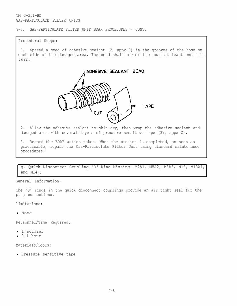
TM 3-251-BDGAS-PARTICULATE FILTER UNITS
9-6. GAS-PARTICULATE FILTER UNIT BDAR PROCEDURES - CONT.
Procedural Steps:
1. Spread a bead of adhesive sealant (2, appx C) in the grooves of the hose oneach side of the damaged area. The bead shall circle the hose at least one fullturn.
2. Allow the adhesive sealant to skin dry, then wrap the adhesive sealant anddamaged area with several layers of pressure sensitive tape (37, appx C).
3. Record the BDAR action taken. When the mission is completed, as soon aspracticable, repair the Gas-Particulate Filter Unit using standard maintenanceprocedures.
g. Quick Disconnect Coupling "O" Ring Missing (M7A1, M8A2, M8A3, M13, M13A1,
General Information:
The “O” rings in the quick disconnect couplings provide an air tight seal for theplug connections.
Limitations:
• None
Personnel/Time Required:
• 1 soldier• 0.1 hour
Materials/Tools:
• Pressure sensitive tape
9-8
and M14).

TM 3-251-BDGAS-PARTICULATE FILTER UNITS
9-6. GAS-PARTICULATE FILTER UNIT BDAR PROCEDURES - CONT.
Procedural Steps:
1. Wrap several layers of pressure sensitive tape (37, appx C) over the quickdisconnect coupling connection.
2. Record the BDAR action taken. When the mission is completed, as soon aspracticable, repair the Gas-Particulate Filter Unit using standard maintenanceprocedures.
h. Electrical Wire Defective (M7A1, M8A2, M8A3, M13, M13A1, and M14).
General Information:
Any broken electrical wire can be repaired by the following BDAR fix.
Limitations:
• None
Personnel/Time Required:
• 1 soldier• 0.1 hour
Materials/Tools:
• Electrical tape• Pliers• Soldering iron• Solder
9-9

TM 3-251-BDGAS-PARTICULATE FILTER UNITS
9-6. GAS-PARTICULATE FILTER UNIT BDAR PROCEDURES - CONT.
Procedural Steps:
1. Remove sufficient insulation from the broken wire ends to allow a minimum offour turns of the wire ends.
2. Twist the wire ends together a minimum of four turns.
3. Solder the twisted wire ends, if possible.
4. Wrap electrical tape (36, appx C) around the exposed wire ends.
5. Record the BDAR action taken. When the mission is completed, as soon aspracticable, repair the Gas-Particulate Filter Unit using standard maintenanceprocedures.
i. Circuit Breaker Defective (M8A2, M8A3, M13, M13A1, and M14).
General Information:
CAUTION
This BDAR fix will eliminate the circuit breakeras a safety device.
For typical location of the circuit breaker and switch assembly (l), refer to thefollowing drawings.
9-10

TM 3-251-BDGAS-PARTICULATE FILTER UNITS
9-6. GAS-PARTICULATE FILTER UNIT BDAR PROCEDURES - CONT.
Limitations:
• None
Personnel/Time Required:
• 1 soldier• 0.1 hour
Materials/Tools:
• None
Procedural Steps:
1. Remove the end of the jumper cable (2) from the air purifier switch.
2. Remove power cable (1) from the circuit breaker and connect to the airpurifier switch.
3. Record the BDAR action taken. When the mission is completed, as soon aspracticable, repair the Gas-Particulate Filter Unit using standard maintenanceprocedures.
j. ON/OFF Switch Defective (M7A1).
General Information:
Limitations:
• None
Personnel/Time Required
• 1 soldier• 0.1 hour
Materials/Tools:
• Screwdriver
This BDAR will bypass the ON/OFF switch. To reenergize the M2A2 Air Purifier,remove the 115 volt ac plug from the power source.
9-11
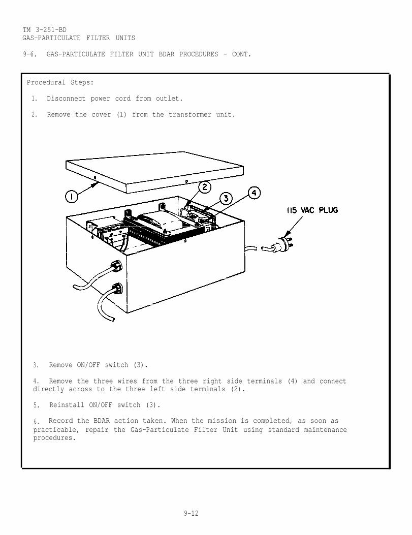
TM 3-251-BDGAS-PARTICULATE FILTER UNITS
9-6. GAS-PARTICULATE FILTER UNIT BDAR PROCEDURES - CONT.
Procedural Steps:
1. Disconnect power cord from outlet.
2. Remove the cover (1) from the transformer unit.
3. Remove ON/OFF switch (3).
4. Remove the three wires from the three right side terminals (4) and connectdirectly across to the three left side terminals (2).
5. Reinstall ON/OFF switch (3).
6. Record the BDAR action taken. When the mission is completed, as soon aspracticable, repair the Gas-Particulate Filter Unit using standard maintenanceprocedures.
9-12

TM 3-251-BD
CHAPTER 10
M51 COLLECTIVE PROTECTION SHELTER SYSTEM
BDAR FIXES SHALL BE USED ONLY IN COMBATAT THE DISCRETION OF THE COMMANDER
AND SHALL BE REPAIRED BY STANDARD MAINTENANCE PROCEDURESAS SOON AS PRACTICABLE AFTER THE MISSION IS COMPLETED.
SECTION I. INTRODUCTION
10-1. SCOPE .
This chapter contains BDAR procedures applicable to the M51 Collective ProtectionShelter System.
10-2. DESCRIPTION.
The M51 Collective Protection Shelter System is a self-contained unit designed toprovide collective protection for up to 10 occupants against all known chemical-biological (CB) agents.
10-3. ASSESSMENT PROCEDURE.
a. Visually Inspect Damage Observed on:-Engine . . . . . . . . . . . . . . . . . . . . . Section II-Shelter System . . . . . . . . . . . . . Section III
No DamageApparent
b. Attempt to Operate Will Not Operate:-Check Engine . . . . . . . . . . . . . . . Section II-Check Shelter System . . . . . . . Section III
Operates
No SignificantDamage andUnit Works ok.
10-1
TM 3-251-BDM51 SHELTER SYSTEM
10-4. REPAIR PROCEDURE INDEX.
a. EngineElectrical System Failures. . . . . . . . . . . . . . . . . . . . . . . . . . . . .
Cracked BatteryElectrical Wire DefectiveLow Oil Pressure Switch (S16) Defective
Fuel System Failures . . . . . . . . . . . . . . . . . . . . . . . . . . . Fuel Fitting LeakingFuel Tank Leaking
b. ShelterElectrical System Failures . . . . . . . . . . . . . . . . . . . . .
AUXILIARY 120 VAC Circuit Breaker (CB1) DefectiveGENERATOR FREQUENCY Meter DefectiveRECIRCULATION FAN Circuit Breaker (CB2) DefectiveCONDENSER FAN Circuit Breaker (CB3) DefectivePRESS TO INFLATE Switch (S3) DefectiveENGINE START Switch (S17) DefectiveENGINE CONTROL Switch (S15) DefectiveRelay K3 DefectiveRelay K8 DefectiveRelay K10 DefectiveRelay K1 DefectiveThermostat Switch (S5) DefectiveLIGHT SWITCH (S2) on the Auxiliary Control Box DefectiveSwitching Relay Kll on the Auxiliary Control Box Defective
Para.
10-6a
10-6b
10-7a
Entrance Time Delay Relay K5 on the Auxiliary Control Box DefectiveBUZZER SILENCER Switch (S23) on the Auxiliary Control Box Defective
Pressurization System Failures. . . . . . . . . . . . . . . . . . . . . . . 10-8bMakeup Air Solenoid DefectiveHose Clamp BrokenLow Air Pressure Switch (S13) DefectiveLow Air Pressure Buzzer Defective
Environment Control System Failures . . . . . . . . . . . . . . . . 10-8cHeater Unit DefectiveHIGH LOW HEAT Switch (S9) on the Auxiliary Control Box DefectiveCooling Unit DefectiveCOOL CIRCULATE HEAT Switch (S4) on the Auxiliary Control Box
Defective
SECTION II. ENGINE
10-5. GENERAL .
NOTE
The M12A1 Decontaminating Apparatus uses the same engine asthe M51 Shelter System. The engine or parts of the enginefrom the M12A1 Decontaminating Apparatus can be cannibalizedand used on the M51 Shelter System.
This section contains BDAR procedures applicable to the engine.
10-2

TM 3-251-BDM51 SHELTER SYSTEM
10-5. GENERAL - CONT.
a. Visually Inspect Damage Found on:-Electrical System . . . . . . . . . . Para. 10-6a-Fuel System . . . . . . . . . . . . . . Para. 10-6b
No Damage
b. Attempt to Start. Will Not Start:Engine -Electrical System . . . . . . . . . . Para. 10-6a
-Fuel System . . . . . . . . . . . . . . Para. 10-6bOperates
No DamageApparent
10-6. ENGINE BDAR PROCEDURES.
a. Electrical System Failures.
(1) Cracked battery.
General Information:
The battery can be repaired without affecting the operation of the engine.
Limitations:
• None
Personnel/Time Required:
• 1 soldier• 0.2 hour
Materials/Tools:
• Epoxy
10-3
Apparent

TM 3-251-BDM51 SHELTER SYSTEM
10-6. ENGINE BDAR PROCEDURES - CONT.
Procedural Steps:
Disconnect ground cable first before removing the battery.Always wear eye protection when working with the batteryto prevent injury to eyes.
1. Remove battery to a suitable work area.
2. Liberally coat the cracked area of the battery with epoxy (15, appx C) andallow to cure.
3. Fill battery with acid solution, if necessary.
4. Reinstall battery.
5. Record the BDAR action taken. When the mission is completed, as soon aspracticable, repair the engine using standard maintenance procedures.
(2) Electrical wire defective.
General Information:
Any broken electrical wire can be repaired by the following BDAR fix.
Limitations:
• None
Personnel/Time Required
• 1 soldier• 0.2 hour
Materials/Tools:
• Electrical tape• Electrician’s pliers• Soldering iron• Solder
10-4
WARNING

TM 3-251-BDM51 SHELTER SYSTEM
10-6. ENGINE BDAR PROCEDURES - CONT.
Procedural Steps:
1. Remove sufficient insulation from the broken wire ends to allow a minimum offour twists of the wire ends.
2. Twist the wire ends together a minimum of four twists.
3. Solder the twisted wired ends, if possible.
4. Wrap electrical tape (36, appx C) around exposed wire ends.
5. Record the BDAR action taken. When the mission is completely as soon aspracticable, repair the engine using standard maintenance procedures.
(3) Low oil pressure switch (S16) defective.
CAUTION
With a defective low oil pressure switch youhave no low oil pressure light, check the oillevel frequently.
NOTE
The engine can be operated with a defectivelow oil pressure switch.
b. Fuel System Failures.
(1) Fuel fitting leaking.
General Information:
A leaking fitting can be repaired without affecting the operation of the engine.The fitting should be tightened first to attempt to stop the leak.
10-5

TM 3-251-BDM51 SHELTER SYSTEM
Limitations:
• None
10-6. ENGINE BDAR PROCEDURES - CONT.
Personnel/Time Required:
• 1 soldier• 0.3 hour
Materials/Tools:
• Fuel resistant sealant (silicone, rubber, or similar material)• Twine or light tie cord
Procedural Steps:
1. Remove coupling flange nut.
2. Slide coupling flange nut up and away from flared end.
3. Clean grease, oil, and fuel from flared end.
4. Wrap twine (39, appx C) around flared end of line.
5. Liberally coat twine, with fuel resistant sealant (33, appx C).
6. Reinstall line and tighten coupling flange nut securely.
7. Check for leaks.
8. Record the BDAR action taken. When the mission is complated, as soonas practicable, repair the engine using standard maintenance procedures.
10-6

TM 3-251-BDM51 SHELTER SYSTEM
10-60 ENGINE BDAR PROCEDURES - CONT.
(2) Fuel tank leaking.
General Information:
Stopping of fuel leakage due to holes can be attempted without removing tank. Ifthe fuel leak is inaccessible, remove the fuel tank.
Limitations:
• None
Personnel/Time Required:
• 2 soldiers• 1.0 hour
Materials/Tools:
• Wooden peg• Adhesive sealant• synthetic rubber sealant
Procedural Steps:
1. Remove-fuel tank, if required.
2. Clean area around holes and fill with adhesive sealant (2, appx C).
3. If hole is too large to be filled, use a wooden peg, cover outside of pegwith sealant, (33, appx C) and place in the hole.
4. Record the BDAR action taken. When the mission is completed, as soon aspracticable, repair the engine using standard maintenance procedures.
10-7

TM 3-251-BDM51 SHELTER SYSTEM
SECTION III. SHELTER
10-7. SHELTER BDAR PROCEDURES.
a. Electrical System Failures.
(1) AUXILIARY 120 VAC circuit breaker (CB1) defective.
General Information:
CAUTION
Circuit breaker (CB1) can be bypassed with a 10 amp fuse.In the absence of a fuse, use regular wire. The use ofregular wire will eliminate the 10 amp safety factor.
Limitations:
• None
Personnel/Time Required:
• 1 soldier• 0.2 hour
Materials/Tools:
• 10 amp fuse• Soldering iron• Electrical wire (16 AWG or larger)• Solder
Procedural Steps:
1. Remove main control indicator access cover by releasing the three fasteners.
2. Cut two pieces of electrical wire (43, appx C) 2 inches in length and removel/2-inch of insulation from each end.
10-8
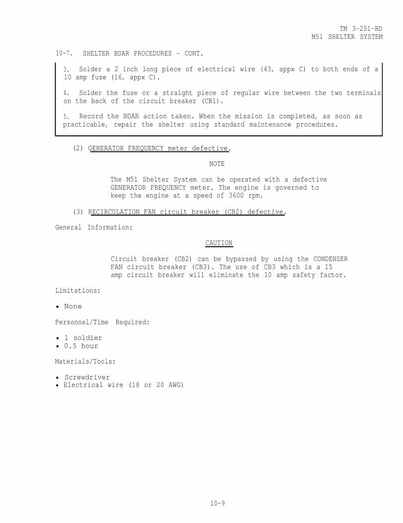
TM 3-251-BDM51 SHELTER SYSTEM
10-7. SHELTER BDAR PROCEDURES - CONT.
3. Solder a 2 inch long piece of electrical wire (43, appx C) to both ends of a10 amp fuse (16, appx C).
4. Solder the fuse or a straight piece of regular wire between the two terminalson the back of the circuit breaker (CB1).
5. Record the BDAR action taken. When the mission is completed, as soon aspracticable, repair the shelter using standard maintenance procedures.
(2) GENERATOR FREQUENCY meter defective.
NOTE
The M51 Shelter System can be operated with a defectiveGENERATOR FREQUENCY meter. The engine is governed tokeep the engine at a speed of 3600 rpm.
(3) RECIRCULATION FAN circuit breaker (CB2) defective.
General Information:
CAUTION
Circuit breaker (CB2) can be bypassed by using the CONDENSERFAN circuit breaker (CB3). The use of CB3 which is a 15amp circuit breaker will eliminate the 10 amp safety factor.
Limitations:
• None
Personnel/Time Required:
• 1 soldier• 0.5 hour
Materials/Tools:
• Screwdriver• Electrical wire (18 or 20 AWG)
10-9
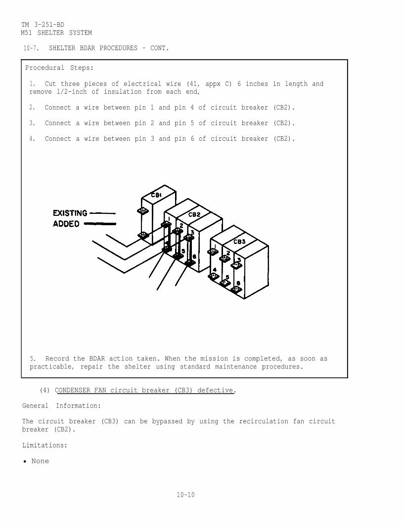
TM 3-251-BDM51 SHELTER SYSTEM
10-7. SHELTER BDAR PROCEDURES - CONT.
Procedural Steps:
1. Cut three pieces of electrical wire (41, appx C) 6 inches in length andremove l/2-inch of insulation from each end,
2.
3.
4.
5.
Connect a wire between pin 1 and pin 4 of circuit breaker (CB2).
Connect a wire between pin 2 and pin 5 of circuit breaker (CB2).
Connect a wire between pin 3 and pin 6 of circuit breaker (CB2).
Record the BDAR action taken. When the mission is completed, as soon aspracticable, repair the shelter using standard maintenance procedures.
(4) CONDENSER FAN circuit breaker (CB3) defective.
General Information:
The circuit breaker (CB3) can be bypassed by using the recirculation fan circuitbreaker (CB2).
Limitations:
• None
10-10

TM 3-251-BDM51 SHELTER SYSTEM
• 1 soldier• 0.3 hour
10-7. SHELTER BDAR PROCEDURES - CONT.
Personnel/Time Required:
Materials/Tools:
• Screwdriver
Procedural Steps:
1. Remove main control indicator access cover by releasing the three fasteners.
2. Disconnect the wire from pin 1 of circuit breaker (CB3) and connect to pin 1of circuit breaker (CB2).
3. Disconnect the wire from pin 2 of circuit breaker (CB3) and connect to pin 2of circuit breaker (CB2).
4. Disconnect the wire from pin 3 of circuit breaker (CB3) and connect to pin 3of circuit breaker (CB2).
5. Record the BDAR action taken. When the mission is completed, as soon aspracticable, repair the shelter using standard maintenance procedures.
10-11

TM 3-251-BDM51 SHELTER SYSTEM
10-7. SHELTER BDAR PROCEDURES - CONT.
(5) PRESS TO INFLATE switch (S3) defective.
General Information:
The Shelter will inflate without PRESS TO INFLATE switch (S3).
Limitations:
• It will take slightly longer to inflate shelter.
Personnel/Time Required:
• 1 soldier• 0.3 hour
Materials/Tools:
. Screwdriver
(6) ENGINE START switch (S17) defective.
General Information:
The ENGINE START switch (S17) can be bypassed by using the PANEL LIGHT switch(S24) .
Limitations:
• The panel light will not operate.
Personnel/Time Required:
• 1 soldier• 0.3 hour
Materials/Tools:
• Screwdriver
Procedural Steps:
NOTE
• To prevent switch identification confusion, thefollowing BDAR fix exchanges switches.
• If time does not permit, it is not necessary toexchange switches, just exchange wires. To startengine, press PANEL LIGHT switch.
1. Remove main control indicator access cover by releasing the three fasteners.
2. Disconnect the wires to switch (S17) (2) and mark the wires.
10-12

TM 3-251-BDM51 SHELTER SYSTEM
10-7. SHELTER BDAR PROCEDURES - CONT.
3. Mark and disconnect the wires to switch (S24) (l).
4. Remove switch (S17) (2) and lay aside.
5. Remove push switch (S24) (1) and install in the hole where switch (S17) wasremoved.
6. Reconnect the wires marked S17 to the switch installed in step 5.
7. Install the switch removed in step 4 in the remaining hole.
8. Reconnect the wires marked S24 to the switch.
9. Record the BDAR action taken. When the mission is completed, as soon aspracticable, repair the shelter using standard maintenance procedures.
(7) ENGINE CONTROL switch (S15) defective.
General Information:
The ENGINE CONTROL switch (S15) can be bypassed without affecting the operation ofthe engine. To shut off the engine, idle the engine downs and pull out the manualchoke lever.
10-13

TM 3-251-BDM51 SHELTER SYSTEM
10-7. SHELTER BDAR PROCEDURES - CONT.
Limitations:
• None
Personnel/Time Required:
• 1 soldier• 0.3 hour
Materials/Tools:
• Screwdriver• Knife
Procedural Steps:
1. Remove main control indicator access cover by releasing the three fasteners
2. Remove ENGINE CONTROL switch (S15) for easy accessibility.
3. Disconnect the wire from terminal 3 of switch (S15) and connect to terminal 2.
4. Disconnect the wire from terminal 5 of switch (S15) and connect toterminal 6.5. Reinstall switch (S15).6. Record the BDAR action taken. When the mission is completed, as soon aspracticable, repair the shelter using standard maintenance procedures.
10-14
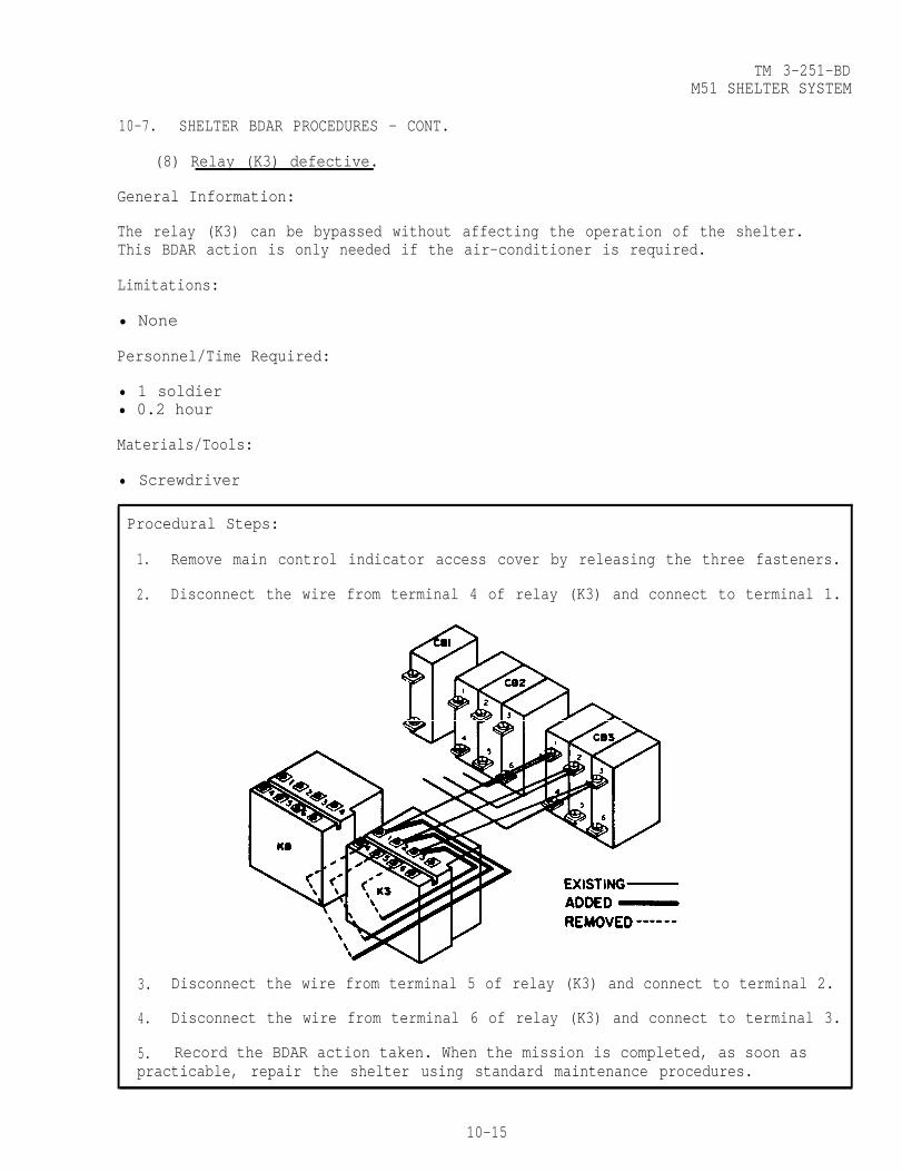
TM 3-251-BDM51 SHELTER SYSTEM
10-7. SHELTER BDAR PROCEDURES - CONT.
(8) Relay (K3) defective.
General Information:
The relay (K3) can be bypassed without affecting the operation of the shelter.This BDAR action is only needed if the air-conditioner is required.
Limitations:
• None
Personnel/Time Required:
• 1 soldier• 0.2 hour
Materials/Tools:
• Screwdriver
Procedural Steps:
1. Remove main control indicator access cover by releasing the three fasteners.
2. Disconnect the wire from terminal 4 of relay (K3) and connect to terminal 1.
3. Disconnect the wire from terminal 5 of relay (K3) and connect to terminal 2.
4. Disconnect the wire from terminal 6 of relay (K3) and connect to terminal 3.
5. Record the BDAR action taken. When the mission is completed, as soon aspracticable, repair the shelter using standard maintenance procedures.
10-15

TM 3-251-BDM51 SHELTER SYSTEM
10-7. SHELTER BDAR PROCEDURES - CONT.
(9) Relay (K8) defective.
General Information:
The relay (K8) can be bypassed without affecting the operation of the shelter.
Limitations:
• None
Personnel/Time Required:
• 1 soldier• 0.2 hour
Materials/Tools:
• Screwdriver
Procedural Steps:
1. Remove main control indicator access cover by releasing the three fasteners.
2. Disconnect the wire from terminal 4 of relay (K8) and connect to terminal 1.
3. Disconnect the wire from terminal 5 of relay (K8) and connect to terminal 2.
4. Disconnect the wire from terminal 6 of relay (K8) and connect to terminal 3.
5. Record the BDAR action taken. When the mission is completed, as soon aspracticable, repair the shelter using standard maintenance procedures.
10-16

TM 3-251-BDM51 SHELTER SYSTEM
10-7. SHELTER BDAR PROCEDURES - CONT.
(10) Relay (K10) defective,
General Information:
The defective contacts in relay (K10) can be bypassed without affecting theoperation of the shelter by using the spare contacts of relay (K10).
Limitations:
• None
Personnel/Time Required:
• 1 soldier• 0.2 hour
Materials/Tools:
• Screwdriver• Cross tip screwdriver
1.
2.
Procedural Steps:
Remove main control indicator access cover by releasing the three fasteners.
Loosen the screw holding the angle bracket and move the angle bracket to theside; remove relay (K10) from socket.
3. Disconnect the wire from terminal 1 of relay (K10) socket and connect toterminal 8.
4. Disconnect the wire from terminal 3 of relay (K10) socket and connect toterminal 6.
5. Reinstall relay (K10) into socket.
6. Record the BDAR action taken. When the mission is completed, as soon aspracticable, repair the shelter using standard maintenance procedures.
10-17

TM 3-251-BDM51 SHELTER SYSTEM
10-7. SHELTER BDAR PROCEDURES - CONT.
(11) Relay (K1) defective.
General Information:
CAUTION
The time delay relay (K1) can be bypassed. In the absenceof the time delay relay, there will be no delay in energizingrelay (K3). Make sure COOL CIRCULATE HEAT switch (S4) is in
Limitations:
• None
Personnel/Time Required:
• 1 soldier• 0.2 hour
Materials/Tools:
the CIRCULATE position when setting RECIRCULATION FAN circuitbreaker (CB2) to the ON position.
• Electrical wire (20 AWG)
• Cross tip screwdriver
Procedural Steps:
1. Remove main control indicator access cover by releasing the three fasteners.
2. Loosen screw holding the angle bracket and move bracket to the side.
3. Remove relay (K1).
4. Wrap a piece of electrical wire (41, appx C) between pins 5 and 7 ofrelay (K1).
5. Reinstall relay (K1).
10-18
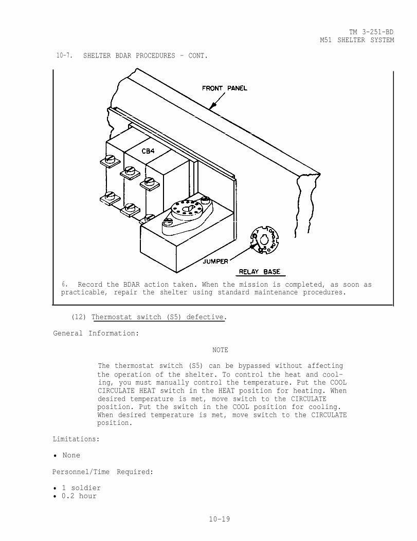
10-7.
6.
TM 3-251-BDM51 SHELTER SYSTEM
SHELTER BDAR PROCEDURES - CONT.
Record the BDAR action taken. When the mission is completed, as soon aspracticable, repair the shelter using standard maintenance procedures.
(12) Thermostat switch (S5) defective.
General Information:
NOTE
The thermostat switch (S5) can be bypassed without affectingthe operation of the shelter. To control the heat and cool-ing, you must manually control the temperature. Put the COOLCIRCULATE HEAT switch in the HEAT position for heating. Whendesired temperature is met, move switch to the CIRCULATEposition. Put the switch in the COOL position for cooling.When desired temperature is met, move switch to the CIRCULATEposition.
Limitations:
• None
Personnel/Time Required:
• 1 soldier• 0.2 hour
10-19
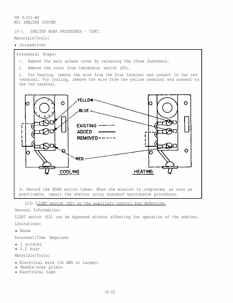
TM 3-251-BDM51 SHELTER SYSTEM
10-7. SHELTER BDAR PROCEDURES - CONT.
Materials/Tools:
• Screwdriver
Procedural Steps:
1. Remove the main access cover by releasing the three fasteners.
2. Remove the cover from thermostat switch (S5).
3. For heating, remove the wire from the blue terminal and connect to the redterminal. For cooling, remove the wire from the yellow terminal and connect tothe red terminal.
4. Record the BDAR action taken. When the mission is completed, as soon aspracticable, repair the shelter using standard maintenance procedures.
(13) LIGHT switch (S2) on the auxiliary control box defective.
General Information:
LIGHT switch (S2) can be bypassed without affecting the operation of the shelter.
Limitations:
• None
Personnel/Time Required:
• 1 soldier• 0.2 hour
Materials/Tools:
• Electrical wire (16 AWG or larger)• Needle-nose pliers• Electrical tape
10-20

TM 3-251-BDM51 SHELTER SYSTEM
10-7. SHELTER BDAR PROCEDURES - CONT.
Procedural Steps:
1. Remove the back cover from the auxiliary control box.
2. Remove one screw holding angle bracket which secures relay K5. Loosen otherscrew and move angle bracket to the side.
3. Remove relay (K5) and lay aside.
4. Cut wires to S2; remove sufficient insulation to allow a minimum of fourtwists to wire ends.
5. Twist wire ends together a minimum of four twists.
6. Wrap electrical tape (36, appx C) around exposed wire ends.
7. Record the BDAR action taken. When the mission is completed, as soon aspracticable, repair the shelter using standard maintenance procedures.
10-21

TM 3-251-BDM51 SHELTER SYSTEM
10-7. SHELTER BDAR PROCEDURES - CONT.
(14) Switching relay (K11) on the auxiliary control box defective.
General Information:
NOTE.
The shelter can be operated with relay (K11)defective. This will eliminate the 8 minutepurge cycle entry mode. When there is contam-ination around the shelter wait an extra 3minutes. If either light remains lit, coverlights with a piece of tape.
(15) Entrance time delay relay (K5) on the auxiliary control box defective.
General Information:
NOTE
The shelter can be operated with relay (K5)defective. In the absence of relay (K5) use awatch to time entry and exit of the shelter.
(16) BUZZER SILENCER switch (S23) on the auxiliary control box defective.
General Information:
This BDAR fix will silence the low-air buzzer.There will be no audio warning to indicate topersonnel to don masks. YOU must rely on thevisual indication of the MASK light.
Limitations:
• Mask audio warning will not operate.
Personnel/Time Required:
• 1 solder• 0.2 hour
Materials/Tools:
• Adjustable wrench
10-22
WARNING

TM 3-251-BDM51 SHELTER SYSTEM
10-7. SHELTER BDAR PROCEDURES - CONT.
Procedural Steps:
1 Remove the back cover from the auxiliary control box.
2. Remove the bottom nut on the buzzer and disconnect the wire.
3. Reinstall the cover.
4. Record the BDAR action taken. When the mission is completed, as soon aspracticable, repair the shelter using standard maintenance procedures.
10-23

TM 3-251-BDM51 SHELTER SYSTEM
10-7. SHELTER BDAR PROCEDURES - CONT.
b. Pressurization System Failures.
(1) Makeup air solenoid defective.
General Information:NOTE
If a rapid inflation is necessary, the makeup air solenoidcan be bypassed by setting the makeup air damper (1) to theSHUT position. After inflation, set the damper in accordancewith instructions in technical manual.
10-24

TM 3-251-BDM51 SHELTER SYSTEM
10-7. SHELTER BDAR PROCEDURES - CONT.
(2) Hose clamp broken.
General Information:
If a replacement hose clamp is not available. wire can be used as a substitute.
Limitations:
• None
Personnel/Time Required
• 1 soldier• 0.2 hour
Materials/Tools:
• Solid wire, safety wire, or similar items
Procedural Steps:
1. Make a loop in one end of the wire (42, appx C). Twist the wire so that apermanent loop is formed.
2. Loosely wrap the wire once around the hose and pull the other end throughthe loop.
3. While pressing the loop tightly against the hose, pull the wire through theloop as tight as possible. Bend the wire back on itself, crimping it, so thatthe wrap will be tight and secure.
4. Secure the loose end by making one more wrap in the opposite direction of thefirst.
5. Record the BDAR action taken. When the mission is completed, as soon aspracticable, repair the shelter using standard maintenance procedures.
10-25
TM 3-251-BDM51 SHELTER SYSTEM
10-7. SHELTER BDAR PROCEDURES - CONT.
(3) Low air pressure switch (S13) defective.
General Information:
The low air pressure switch (S13) can be bypassed by using the makeup air pressureswitch (S12). This will make the makeup air solenoid inoperative. Use theevacuation fan as the source of makeup air to the entrance and shelter ribs.
NOTE
The mask alarm will come on at a higher air pressurewhen using the makeup air pressure switch. The alarmwill come on at the pressure set by switch (S12).
Limitations:
• None
Personnel/Time Required:
• 1 soldier• 0.2 hour
Materials/Tools:
• Screwdriver
10-26

TM 3-251-BDM51 SHELTER SYSTEM
10-7. SHELTER BDAR PROCEDURES - CONT.
Procedural Steps:
1. Remove main control indicator access cover by releasing the three fasteners.
2. Loosen the screws securing the covers on switches (S12) and (S13) and removecovers.
3. Disconnect the wires from switch (S12) and mark the wire.
4. Disconnect the wire from the common terminal on switch (S13) and connect tothe common terminal on switch (S12).
5. Disconnect the wire from the normally closed terminal on switch (S13) andconnect to the normally closed terminal on switch (S12).
6. Turn adjustment screw full counter clockwise.
7. Reinstall the covers on switches (S12) and (S13).
8. Reinstall control indicator access cover.
8. Record the BDAR action taken. When the mission is completed, as soon aspracticable, repair the shelter using standard maintenance procedures.
10-27

TM 3-251-BDM51 SHELTER SYSTEM
10-7. SHELTER BDAR PROCEDURES - CONT.
(4) Low air pressure buzzer defective.
NOTE
The shelter can be operated with a defective buzzer.There will be no audio warning. Visually check thered MASK light for low air pressure.
c. Environment Control System Failures.
(1)
(2)
(3)
(4)
Heater unit defective.
CAUTION
Heaters that require the exhaust to be vented cannotbe used with the shelter. Damage to the equipment willresult.
NOTE
The shelter can be operated without a heater unit.
HIGH LOW HEAT switch (S9) on the auxiliary control box defective.
NOTE
The shelter can be operated with a defective HIGH LOWHEAT switch (S9). If the switch is open, you are in theLOW HEAT switch. If the switch is closed, you are inthe HIGH HEAT position.
Cooling unit defective.
NOTE
The shelter can be operated with a defective coolingunit. The recirculation fan will help keep the sheltercool .
COO1 CIRCULATE HEAT switch (S4) on the auxiliary control box defective.
The COOL CIRCULATE HEAT switch (S4) can be bypassed without affecting the operationof the shelter.
Limitations:
• Changing from HEAT to COOL will require switching the wires.
Personnel/Time Required:
• 1 soldier• 0.3 hour
10-28
General Information
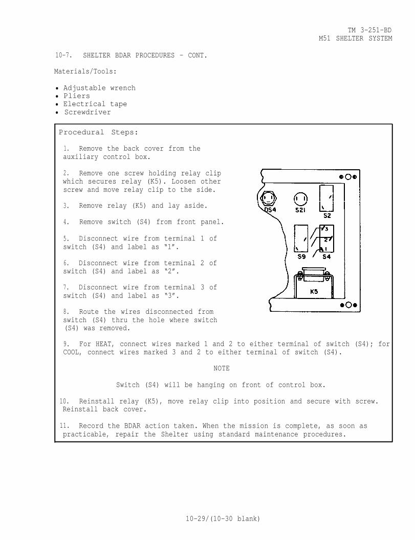
TM 3-251-BDM51 SHELTER SYSTEM
10-7. SHELTER BDAR PROCEDURES - CONT.
Materials/Tools:
• Adjustable wrench• Pliers• Electrical tape• Screwdriver
Procedural Steps:
1. Remove the back cover from theauxiliary control box.
2. Remove one screw holding relay clipwhich secures relay (K5). Loosen otherscrew and move relay clip to the side.
3. Remove relay (K5) and lay aside.
4. Remove switch (S4) from front panel.
5. Disconnect wire from terminal 1 ofswitch (S4) and label as “1”.
6. Disconnect wire from terminal 2 ofswitch (S4) and label as “2”.
7. Disconnect wire from terminal 3 ofswitch (S4) and label as “3”.
8. Route the wires disconnected fromswitch (S4) thru the hole where switch(S4) was removed.
9. For HEAT, connect wires marked 1 and 2 to either terminal of switch (S4); forCOOL, connect wires marked 3 and 2 to either terminal of switch (S4).
NOTE
Switch (S4) will be hanging on front of control box.
10. Reinstall relay (K5), move relay clip into position and secure with screw.Reinstall back cover.
11. Record the BDAR action taken. When the mission is complete, as soon aspracticable, repair the Shelter using standard maintenance procedures.
10-29/(10-30 blank)

TM 3-251-BD
CHAPTER 11
HOODS, CHEMICAL-BIOLOGICAL MASK: M5, M6A2, M7, M40, AND M42
BDAR FIXES SHALL BE USED ONLY IN COMBATAT THE DISCRETION OF THE COMMANDER
AND SHALL BE REPAIRED BY STANDARD MAINTENANCE PROCEDURESAS SOON AS PRACTICABLE AFTER THE MISSION IS COMPLETED.
SECTION I. INTRODUCTION
11-1. SCOPE.
This chapter contains BDAR procedures applicable to the Chemical-Biological Mask Hoods M5, M6A2, M7, M40, and M42.
11-2. DESCRIPTION.
The Chemical-Biological Mask Hood is a protective garment that isworn over your head and neck to protect you from toxic vapors ordroplets.
11-3. ASSESSMENT PROCEDURE.
Visually Inspect Damage Observed on:
11-4.
-Mask Hood.................. Section II
No DamageApparent
No SignificantDamage andUnit Works ok.
REPAIR PROCEDURE INDEX. Para.
Hood Torn or Cut . . . . . . . . . . . . . . . . . . . . . . . . . . . . . . . . . . . 11-6aNeck Cord Missing or Torn . . . . . . . . . . . . . . . . . . . . . . . . . . . . . . . . . 11-6bUnderarm Straps Torn . . . . . . . . . . . . . . . . . . . . . . . . . . . . . . . . . . . . . . 11-6cHose Cord Missing or Torn. . . . . . . . . . . . . . . . . . . . . . . . . . . . . . . . . . 11-6dZipper Broken . . . . . . . . . . . . . . . . . . . . . . . . . .. . . 11-6e
Change 3 11-1

TM 3-251-BDCHEMICAL-BIOLOGICAL MASK HOODS
SECTION II. HOODS, CHEMICAL-BIOLOGICAL MASK: M5, M6A2, M7,M40 and M42
11-5. GENERAL.
This section contains BDAR procedures applicable to the Chemical-Biological Mask Hoods; M5, M6A2, M7, M40 and M42.
11-6. MASK HOOD BDAR PROCEDURES.
NOTE
Each BDAR fix pertains only to the Mask Hoodslisted in parenthesis.
a. Hood Torn or Cut (MS, M6A2, and M7, M40 and M42).
General Information:
If no Chemical-Biological Mask Hood is available, use the hood ofa poncho.
Limitations:
• Moisture may need to be removed for this procedure to be effective.
Personnel/Time Required:
• 1 or 2 soldiers• 0.1 hour
Materials/Tools:
• Pressure sensitive tape
Procedural Steps:
NOTE
The assistance of another soldier may berequired for this procedure.
1. Estimate size of hole or tear.
2. Cut a piece or pieces of pressure sensitive tape (37, appx C) at least 1 inchlonger than the hole.
3. Cover outside torn area of mask hood with pressure sensitive tape.
4. Repeat steps 3 and 4 for inside of mask hood, if not wearing mask at the time
repair is made.
11-2 Change 3

11-6.
TM 3-251-BDCHEMICAL-BIOLOGICAL MASK HOODS
MASK HOOD BDAR PROCEDURES - CONT.
practicable, replace mask hood with a fully serviceable item.
b. Neck Cord Missing or Torn (M5, M6A2, M7, M40 and M42 .
General Information:
Limitations:
• None
Personnel/Time Required
• 1 soldier• 0.1 hour
Materials/Tools:
• Footwear lace or similar item
The neck cord is used to tighten the mask hood around the neck.
Change 3 11-3
5.Record the BDAR action taken. When the mission is completed, as soon as

TM 3-251-BDCHEMICAL-BIOLOGICAL MASK HOODS
11-6. MASK HOOD BDAR PROCEDURES - CONT.
Procedural Steps:
1. Place footwear lace (23, appx C) through loops on the mask hood and fastenwith slide fastener. If the slide fastener is missing, tie the footwear lace ina bow.
2. Record the BDAR action taken. When the mission is completed, as soon aspracticable, replace mask hood with a fully serviceable item.
c. Underarm Straps Torn or Missing (M5, M6A2, M7, M40 and M42).
General Information:
Underarm straps are used to hold the mask hood in place.
Limitations:
• None
Personnel/Time Required:
• 1 soldier• 0.1 hour
Materials/Tools:
• Footwear lace or similar item
11-4 Change 3
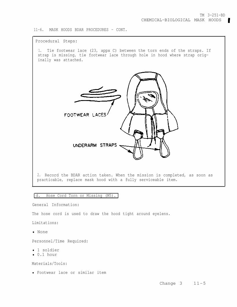
TM 3-251-BDCHEMICAL-BIOLOGICAL MASK HOODS
11-6. MASK HOODS BDAR PROCEDURES - CONT.
Procedural Steps:
1. Tie footwear lace (23, appx C) between the torn ends of the straps. Ifstrap is missing, tie footwear lace through hole in hood where strap orig-inally was attached.
2. Record the BDAR action taken. When the mission is completed, as soon aspracticable, replace mask hood with a fully serviceable item.
d. Hose Cord Torn or Missing (M5).
General Information:
The hose cord is used to draw the hood tight around eyelens.
Limitations:
• None
Personnel/Time Required:
• 1 soldier• 0.1 hour
Materials/Tools:
• Footwear lace or similar item
Change 3 11-5

TM 3-251-BDCHEMICAL-BIOLOGICAL MASK HOODS
11-6. MASK HOODS BDAR PROCEDURES - CONT.
Procedural Steps:
1. Tie footwear lace (23, appx C) to torn cord on mask hood. If cord ismissing, replace it with a footwear lace.
2. Record the BDAR action taken. When the mission is completed, as soon aspracticable, replace mask hood with a fully serviceable item.
e. Zipper Broken (M6A2, M40 and M42).
General Information:
The zipper permits opening of the hood for ventilation or closing for protection.
Limitations:
• Moisture may need to be removed for this procedure to be effective.
Personnel/Time Required:
• 2 soldiers• 0.1 hour
Materials/Tools:
• Pressure sensitive tape
11-6 Change 3

TM 3-251-BDCHEMICAL-BIOLOGICAL MASK HOODS
11-6. MASK HOODS BDAR PROCEDURES - CONT.
Procedural Steps:
1.
NOTE
Estimate the length of the zipper.
than the zipper.
This procedure is always done while wearing hood.
2. Cut a piece of pressure sensitive tape (37, appx C) at least 1 inch longer
3. Tape zipper together with pressure sensitive tape.
4. Record the BDAR action taken. When the mission is completed, as soon aspracticable, replace mask hood with a fully serviceable item.
Change 3 11-7/(11-8 blank)

TM 3-251-BD
CHEMICAL-BIOLOGICAL MASKS:
CHAPTER 12
M9, M9A1, M17A1, M17A2, M24, M25A1,M40, M42 and M43
BDAR FIXES SHALL BE USED ONLY IN COMBATAT THE DISCRETION OF THE COMMANDER AND
SHALL BE REPAIRED BY STANDARD MAINTENANCE PROCEDURESAS SOON AS PRACTICABLE AFTER THE MISSION IS COMPLETED.
SECTION I. INTRODUCTION
12-1. SCOPE . This chapter contains BDAR procedures applicable tothe Chemical-Biological Masks M9, M9A1, M17A1, M17A2, M24, M25A1,M40, M42 and M43.
12-2. DESCRIPTION. The chemical-biological masks protect theface, eyes and lungs from field concentrations of all knownchemical-biological agents.
12-3. ASSESSMENT PROCEDURE.
Visually Inspect --- Damage observed on:-Chemical-Biological Masks. . .Section II
No DamageApparent
No SignificantDamage and UnitWorks OK.
12-4. REPAIR PROCEDURE INDEX.
Lens Cracked . . . . . . . . . . . . . . . . . . . . . . . . . . . . . . . . Head Harness Torn (M9, M9A1; M17A1, M17A2, M24, M25A1
M40, M42 and M43) . . . . . . . . . . . . . . . . Hose Punctured (small holes) (M24, M25A1, M42, and M43)...Hose Punctured (large holes) (M24, M25A1, M42, and M43)...Ratchet Clamp Broken or Missing (M24, M25A1, and M43) . . . . .Hood Torn or Cut (M43) . . . . . . . . . . . . . . . . . . . . . . . . .Hood Neck Closure Not Elastic (M43) . . . . . . . . . . . . . .Blower Casing Cracked or Has Small Holes (M43) . . . . . . . . . . . .Blower Casing Cracked or Has Large Holes (M43) . . . . . . . . . . . .Battery Door Hinges Broken or Latch Inoperable (M43) . . . . . .
Change 3
12-6a
12-6b12-6c12-6d12-6e12-6f12-6g12-6h12-6i12-6j
12-1

TM 3-251-BDCHEMICAL-BIOLOGICAL MASK
SECTION II. CHEMICAL-BIOLOGICAL MASKS: M9, M9A1, M17A1,M17A2, M24, M25A1, M40, M42 and M43
12-5. GENERAL. This section contains BDAR procedures applicableto the Chemical-Biological Masks M9, M9A1, M17A1, M17A2, M24, M25A1,M40, M42 and M43.
12-6. CHEMICAL-BIOLOGICAL MASK BDAR PROCEDURES.
NOTE
Each BDAR fix pertains only to the model of thechemical-biological mask listed in parentheses.
a. Lens Cracked (M24 and M25A1).
General Information:
The cracked area of the lens must be completely free of foreignmatter to perform this BDAR fix.
Limitations:
o The soldier's view will be partially obstructed by this BDARfix.
Personnel\Time Required:
o 1 soldiero 0.1 hour
Materials/Tolls:
o Pressure sensitive tape
12-2 Change 3

TM 3-251-BDCHEMICAL-BIOLOGICAL MASK
1. Wipe all dirt, grease and foreign matter from the area around the crackin the lens.
2. Cut a piece of pressure sensitive tape (37, App C)longer than the crack in the lens.
CAUTION
Care must be taken not to enlarge crack in lens.
3. Center the pressure sensitive tape over the crack on the outside of thelens, and press firmly in place.
4. Repeat steps 2 and 3 for the inside of the lens, if not wearing mask atthe time repair is made.
5. Record the BDAR action taken. When the mission is completed, as soonas practicable, repair the chemical-biological mask using standard mainte-nance procedures.
b. Head Harness Torn (M9, M9A1, M17A1, M17A2, M24, M25A1,M40, M42 and M43).
General Information:
The head harness holds the faceblank tight against the face to form an air-tight seal. Any BDAR fix must also provide an airtight seal.
Limitations:
o This BDAR fix may also slow down putting on and taking off mask.
Personnel/Time Required:
o 2 soldierso 0.1 hour
Materials/Tools:
o Knifeo Footwear lace, small cord or similar items Change 3 12-3
12-6. CHEMICAL-BIOLOGICAL MASK BDAR PROCEDURES. (CONT)
Procedural Steps:
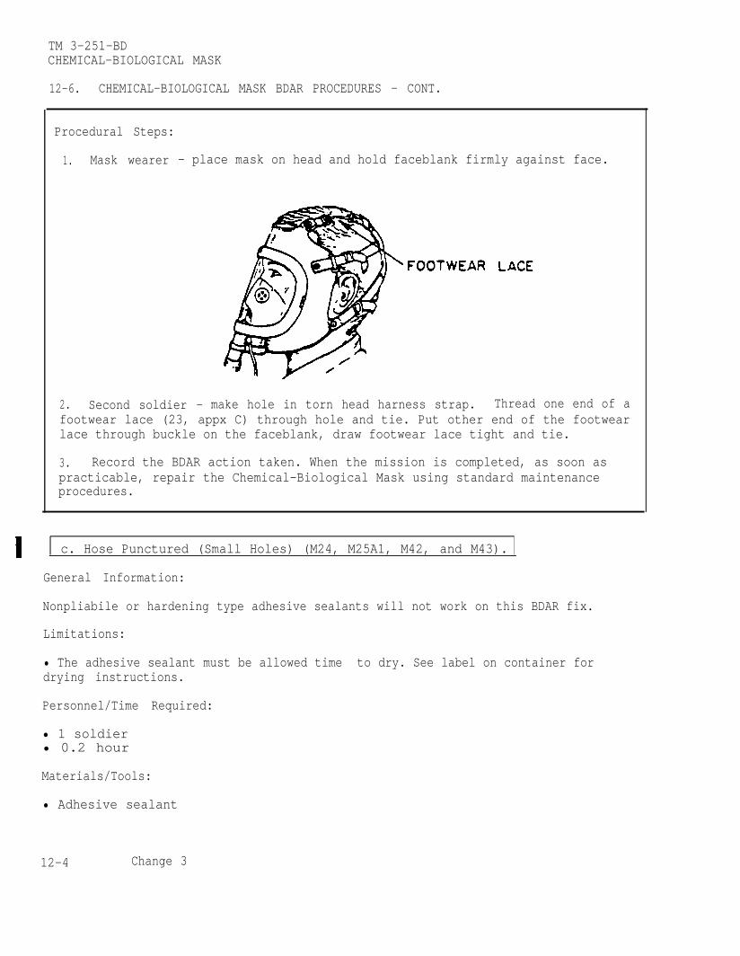
TM 3-251-BDCHEMICAL-BIOLOGICAL MASK
12-6. CHEMICAL-BIOLOGICAL MASK BDAR PROCEDURES - CONT.
Procedural Steps:
1. Mask wearer - place mask on head and hold faceblank firmly against face.
2. Second soldier - make hole in torn head harness strap. Thread one end of afootwear lace (23, appx C) through hole and tie. Put other end of the footwearlace through buckle on the faceblank, draw footwear lace tight and tie.
3. Record the BDAR action taken. When the mission is completed, as soon aspracticable, repair the Chemical-Biological Mask using standard maintenanceprocedures.
c. Hose Punctured (Small Holes) (M24, M25A1, M42, and M43).
General Information:
Nonpliabile or hardening type adhesive sealants will not work on this BDAR fix.
Limitations:
• The adhesive sealant must be allowed time to dry. See label on container fordrying instructions.
Personnel/Time Required:
• 1 soldier• 0.2 hour
Materials/Tools:
• Adhesive sealant
12-4 Change 3

TM 3-251-BDCHEMICAL-BIOLOGICAL MASK
12-6. CHEMICAL-BIOLOGICAL MASK BDAR PROCEDURES - CONT.
Procedural Steps:
1. Apply a liberal amount of adhesive sealant (2, appx C) over the hole in thehose.
2. Allow the adhesive sealant to dry per information on the container.
3. Record the BDAR action taken. When the mission is completed, as soon aspracticable, repair the Chemical-Biological Mask using standard maintenanceprocedures.
d. Hose Punctured (Large Holes) or Cut (M24, M25A1, M42, and M43).
General Information:
Nonpliable or hardening type adhesive sealants will not work on this BDAR fix.
Limitations:
• The adhesive sealant must be allowed time to dry. See label on container fordrying instructions.
Personnel/Time Required:
• 1 soldier• 0.2 hour
Materials/Tools:
• Adhesive sealant• Pressure sensitive tape
Change 3 12-5
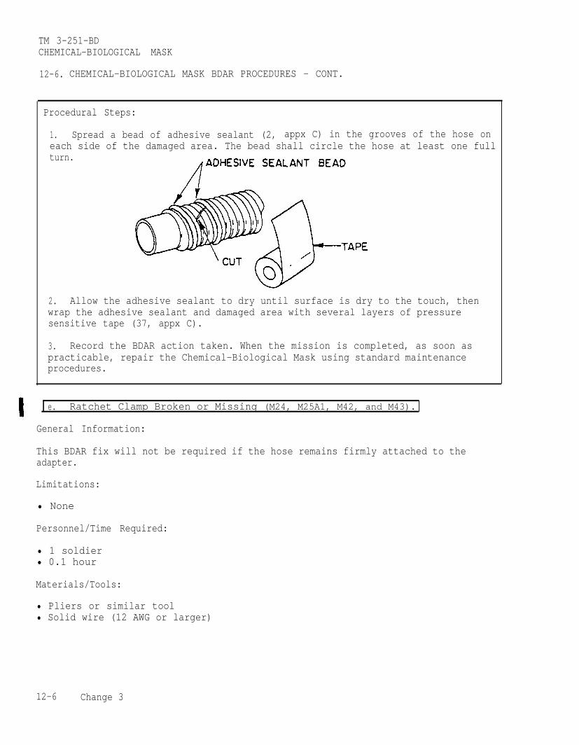
TM 3-251-BDCHEMICAL-BIOLOGICAL MASK
12-6. CHEMICAL-BIOLOGICAL MASK BDAR PROCEDURES - CONT.
Procedural Steps:
1. Spread a bead of adhesive sealant (2, appx C) in the grooves of the hose oneach side of the damaged area. The bead shall circle the hose at least one fullturn.
2. Allow the adhesive sealant to dry until surface is dry to the touch, thenwrap the adhesive sealant and damaged area with several layers of pressuresensitive tape (37, appx C).
3. Record the BDAR action taken. When the mission is completed, as soon aspracticable, repair the Chemical-Biological Mask using standard maintenanceprocedures.
e. Ratchet Clamp Broken or Missing (M24, M25A1, M42, and M43).
General Information:
This BDAR fix will not be required if the hose remains firmly attached to theadapter.
Limitations:
• None
Personnel/Time Required:
• 1 soldier• 0.1 hour
Materials/Tools:
• Pliers or similar tool• Solid wire (12 AWG or larger)
12-6 Change 3
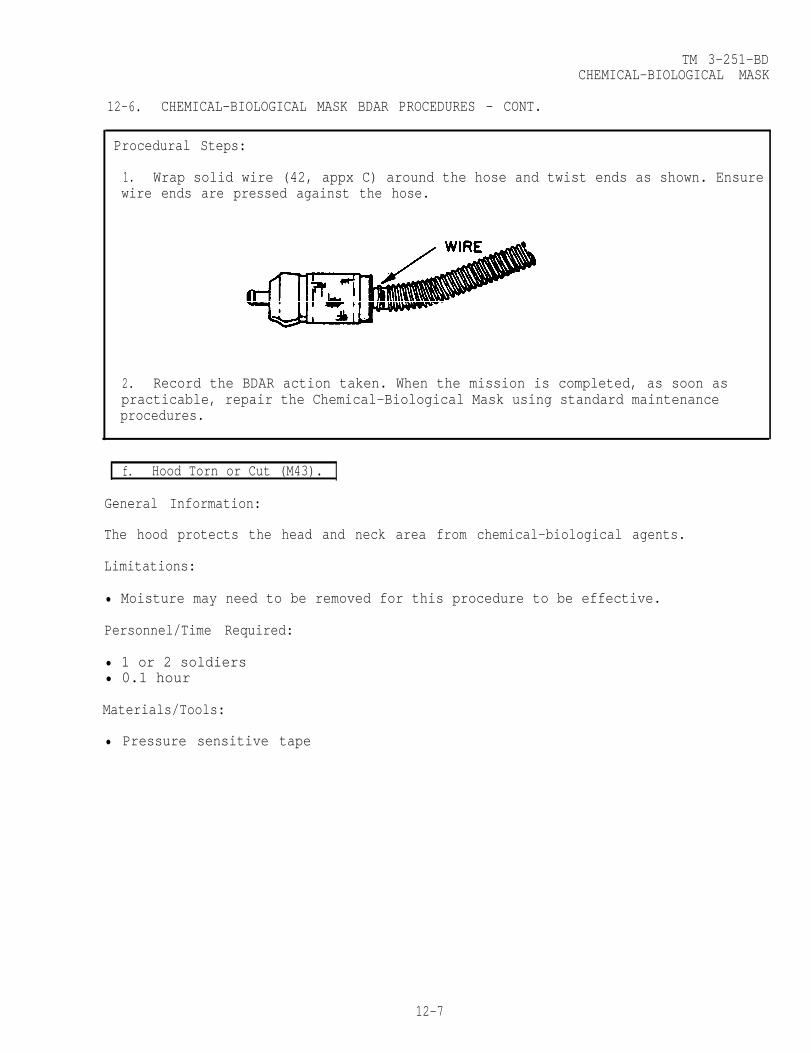
TM 3-251-BDCHEMICAL-BIOLOGICAL MASK
12-6. CHEMICAL-BIOLOGICAL MASK BDAR PROCEDURES - CONT.
Procedural Steps:
1. Wrap solid wire (42, appx C) around the hose and twist ends as shown. Ensurewire ends are pressed against the hose.
2. Record the BDAR action taken. When the mission is completed, as soon aspracticable, repair the Chemical-Biological Mask using standard maintenanceprocedures.
f. Hood Torn or Cut (M43).
General Information:
The hood protects the head and neck area from chemical-biological agents.
Limitations:
• Moisture may need to be removed for this procedure to be effective.
Personnel/Time Required:
• 1 or 2 soldiers• 0.1 hour
Materials/Tools:
• Pressure sensitive tape
12-7

TM 3-251-BDCHEMICAL-B1OLOGICAL MASK
12-6. CHEMICAL-BIOLOGICAL MASK BDAR PROCEDURES - CONT.
Procedural Steps:
NOTE
Assistance of another soldier may be requiredfor this procedure.
1. Clean the torn area of the hood.
2. Estimate size of hole or tear.
3. Cut a piece of pressure sensitive tape (37, appx C) at least 1 inch longerthan tear.
4. Apply pressure sensitive tape over the tear on the outside of the hood.
5. Repeat steps 1 thru 4 for the inside of the hood, if not wearing mask at thetime repair is made.
6. Record the BDAR action taken. When the mission is completed, as soon aspracticable, repair the Chemical-Biological Mask using standard maintenanceprocedures.
g. Hood Neck Closure Not Elastic (M43).
General Information:
The elastic holds the bottom of the hood firmly against the neck.
12-8 Change 3

TM 3-251-BDCHEMICAL-BIOLOGICAL MASK
12-6. CHEMICAL-BIOLOGICAL MASK BDAR PROCEDURES - CONT.
Limitations:
• Securing the hood will require extra time after donning.
Personnel/Time Required
• 1 soldier• 0.1 hour
Materials/Tools:
•Footwear lace, string, small cord, or similar items
Procedural Steps:
NOTE
When performing this BDAR fix, tie footwearlace in a bow to facilitate removal of the mask.
1. Install the mask on head, tie footwear lace (23, appx C) or similar itemaround the bottom of the hoold. The hood should be comfortably tight againstthe neck.
2. Record the BDAR action taken. the mission is completed, as soon aspracticable, repair the Chemical-Biological Mask using standard maintenanceprocedures.
12-9
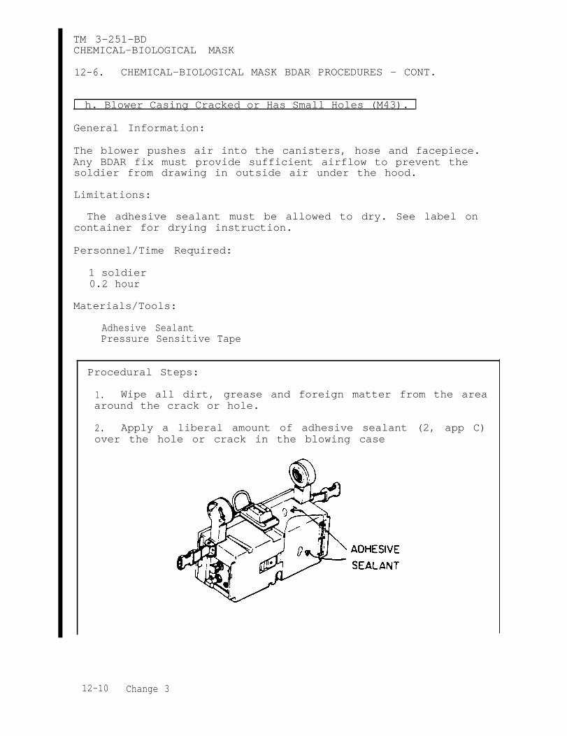
TM 3-251-BDCHEMICAL-BIOLOGICAL MASK
12-6. CHEMICAL-BIOLOGICAL MASK BDAR PROCEDURES - CONT.
h. Blower Casing Cracked or Has Small Holes (M43).
General Information:
The blower pushes air into the canisters, hose and facepiece.Any BDAR fix must provide sufficient airflow to prevent thesoldier from drawing in outside air under the hood.
Limitations:
The adhesive sealant must be allowed to dry. See label oncontainer for drying instruction.
Personnel/Time Required:
1 soldier0.2 hour
Materials/Tools:
Adhesive SealantPressure Sensitive Tape
Procedural Steps:
1. Wipe all dirt, grease and foreign matter from the areaaround the crack or hole.
2. Apply a liberal amount of adhesive sealant (2, app C)over the hole or crack in the blowing case
12-10 Change 3

TM 3-251-BDCHEMICAL-BIOLGOCIAL MASK
12-6. CHEMICAL-BIOLOGICAL MASK BDAR PROCEDURES - CONT.
3. Allow the adhesive sealant to dry until surface is dryto the touch, then cover the adhesive sealant and damagedarea with several layers of pressurized sensitive tape(37, app C).
4. Record the BDAR action taken. When the mission iscompleted, as soon as practicable repair the chemical-biological mask using standard maintenance procedures.
i. Blower Casing Has Large Holes (M43).
General Information:
The blower pushes air into the canisters, hose and facepiece.Any BDAR fix must provide sufficient airflow to prevent thesoldier from drawing in outside air under the hood.
Limitations:
The adhesive sealant must be allowed time to dry. See labelon container for drying instructions.
Personnel/Time Required:
1 soldier0.2 hour
Materials/Tools:
Adhesive SealantPressure Sensitive
Change 3 12-11

TM 3-251-BDCHEMICAL-BIOLOGICAL MASK
12-6. CHEMICAL-BIOLOGICAL MASK BDAR PROCEDURES - CONT.
Procedural Steps:
1. Wipe all dirt, grease and foreign matter from thearea around the hole.
2. Apply a liberal amount of adhesive sealant (2, app C)around the hole. The bead shall circle the entire hole.
3. Allow the adhesive sealant to dry until the surfaceis dry to the trouch, then cover the adhesive sealant anddamaged area with several layers of pressure sensitive tape(37, app C).
4. Record the BDAR action taken. When the mission iscompleted, as soon as practicable repair the chemical-biological mask using standard maintenance procedures.
j. Battery Door Hinges Broken or Latch Inoperable (M43).
General Information:
The battery door is used simply to hold the battery in its com-partment and allow easy access to the battery compartment.
Limitations:
None
12-12 Change 3
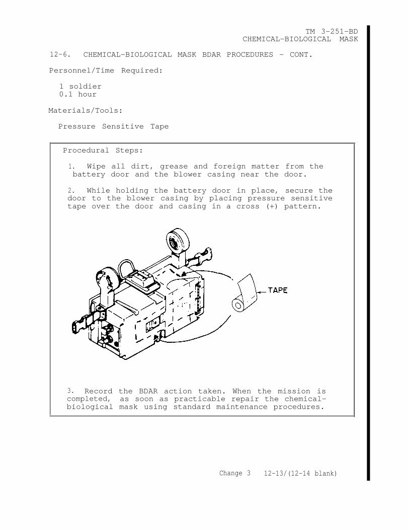
TM 3-251-BDCHEMICAL-BIOLOGICAL MASK
12-6. CHEMICAL-BIOLOGICAL MASK BDAR PROCEDURES - CONT.
Personnel/Time Required:
1 soldier0.1 hour
Materials/Tools:
Pressure Sensitive Tape
Procedural Steps:
1. Wipe all dirt, grease and foreign matter from thebattery door and the blower casing near the door.
2. While holding the battery door in place, secure thedoor to the blower casing by placing pressure sensitivetape over the door and casing in a cross (+) pattern.
3. Record the BDAR action taken. When the mission iscompleted, as soon as practicable repair the chemical-biological mask using standard maintenance procedures.
Change 3 12-13/(12-14 blank)

TM 3-251-BD
CHAPTER 13
M8A1 AUTOMATIC CHEMICAL AGENT ALARM
BDAR FIXES SHALL BE USED ONLY IN COMBATAT THE DISCRETION OF THE COMMANDER
AND SHALL BE REPAIRED BY STANDARD MAINTENANCE PROCEDURESAS SOON AS PRACTICABLE AFTER THE MISSION IS COMPLETED.
SECTION I. INTRODUCTION
13-1. SCOPE .
This chapter contains BDAR procedures applicable to the M8A1 Automatic ChemicalAgent Alarm.
13-2. DESCRIPTION.
The M8A1 Automatic Chemical Agent Alarm provides a method of automaticallydetecting chemical nerve agents in the air and then sounds an alarm. The unit canbe hand carried, vehicle mounted, backpacked, or ground emplaced.
WARNING
Radiation danger. If cell module is removed,disposable gloves shall be used.
13-3. ASSESSMENT PROCEDURE.
NOTE
Under normal operation conditions, the pump moduleand the cell module are not to be exchanged. However,under combat conditions, modules from more than onealarm can be combined to obtain a usable unit.
a. Visually Inspect Damage Observed on:-M8A1 Automatic ChemicalAgent Alarm
No DamageApparent
. . . . . . . . . . . . . Section II
13-1

TM 3-251-BDM8A1 AUTOMATIC CHEMICAL AGENT ALARM
13-3. ASSESSMENT PROCEDURE - CONT.
b. Attempt to Operate Will not operate:-M8A1 Automatic ChemicalAgent Alarm . . . . . . . . . . . . . . . Section II
No SignificantDamage andUnit Works ok.
13-4. REPAIR PROCEDURE INDEX. Para.
M43Al Detector Horn Inoperative. . . . . . . . . . . . . . . . . . . . . . . . . . . . . 13-6aBA3517/U Battery Dead . . . . . . . . . . . . . . . . . . . . . . . . . . . . . . . . . 13-6bTest Buttons Broken Off the M43Al Detector . . . . . . . . . . . . . . . . . . . . . 13-6cClamping Catches Broken on M43A1 Detector . . . . . . . . . . . . . . . . . . 13-6dM43A1 Detector Case Punctured or Cracked . . . . . . . . . . . . . . . . . . . . . . 13-6e
SECTION II. M8A1 AUTOMATIC CHEMICAL AGENT ALARM
13-5. GENERAL.
This section contains BDAR procedures applicable to the M8A1 Automatic ChemicalAgent Alarm.
13-6. M8A1 AUTOMATIC CHEMICAL AGENT ALARM PROCEDURES.
a. M43A1 Detector Horn Inoperative.
General Information:
The horn sounds when chemical agents are detected.
Limitations:
• The M43A1 will still detect chemical agents but no audio alert will sound
Personnel/Time Required:
• 1 soldier• 0.2 hour
Materials/Tools:
• Telephone cable or 2 conductor wire• Wire strippers• M42 alarm
13-2
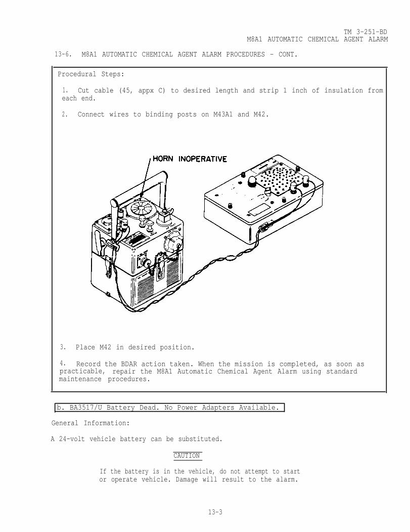
TM 3-251-BDM8A1 AUTOMATIC CHEMICAL AGENT ALARM
13-6. M8A1 AUTOMATIC CHEMICAL AGENT ALARM PROCEDURES - CONT.
Procedural Steps:
1. Cut cable (45, appx C) to desired length and strip 1 inch of insulation fromeach end.
2. Connect wires to binding posts on M43A1 and M42.
3. Place M42 in desired position.
4. Record the BDAR action taken. When the mission is completed, as soon aspracticable, repair the M8A1 Automatic Chemical Agent Alarm using standardmaintenance procedures.
b. BA3517/U Battery Dead. No Power Adapters Available.
General Information:
A 24-volt vehicle battery can be substituted.
CAUTION
If the battery is in the vehicle, do not attempt to startor operate vehicle. Damage will result to the alarm.
13-3

TM 3-251-BDM8A1 AUTOMATIC CHEMICAL AGENT ALARM
13-6. M8A1 AUTOMATIC CHEMICAL AGENT ALARM PROCEDURES - CONT.
Limitations:
• None
Personnel/Time Required:
• 1 soldier• 0.1 hour
Materials/Tools:
• 24-volt battery or 24-volt system (vehicle)• BA3517/U battery (defective)• Wire strippers
Procedural Steps:
1. Cut the plug off the defective BA3517/U battery, as close to battery aspossible.
2. Strip the insulation off the plug wires.
CAUTION
Connect + side of battery to the + side of plug ordamage will result to alarm. Ribbed side of cordis positive.
13-4
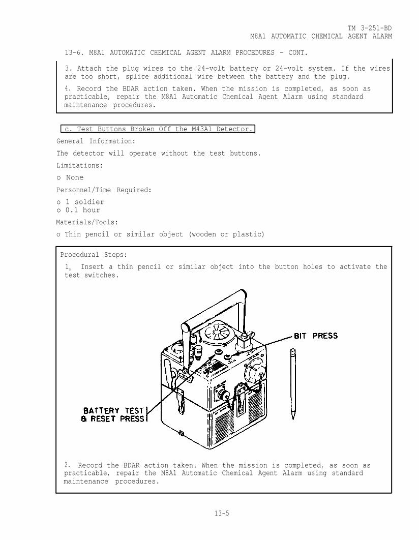
TM 3-251-BDM8A1 AUTOMATIC CHEMICAL AGENT ALARM
13-6. M8A1 AUTOMATIC CHEMICAL AGENT ALARM PROCEDURES - CONT.
3. Attach the plug wires to the 24-volt battery or 24-volt system. If the wiresare too short, splice additional wire between the battery and the plug.
4. Record the BDAR action taken. When the mission is completed, as soon aspracticable, repair the M8A1 Automatic Chemical Agent Alarm using standardmaintenance procedures.
c. Test Buttons Broken Off the M43A1 Detector.
General Information:
The detector will operate without the test buttons.
Limitations:
o None
Personnel/Time Required:
o 1 soldiero 0.1 hour
Materials/Tools:
o Thin pencil or similar object (wooden or plastic)
Procedural Steps:
10 Insert a thin pencil or similar object into the button holes to activate thetest switches.
2. Record the BDAR action taken. When the mission is completed, as soon aspracticable, repair the M8A1 Automatic Chemical Agent Alarm using standardmaintenance procedures.
13-5
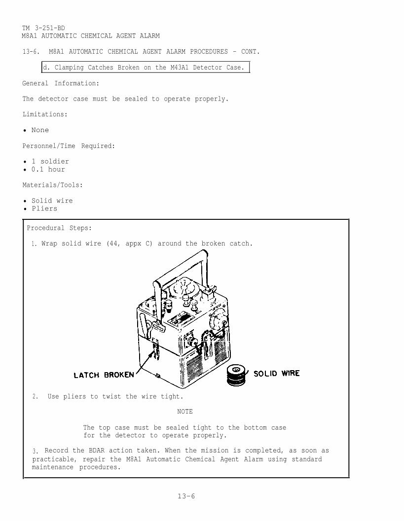
TM 3-251-BDM8A1 AUTOMATIC CHEMICAL AGENT ALARM
13-6. M8A1 AUTOMATIC CHEMICAL AGENT ALARM PROCEDURES - CONT.
d. Clamping Catches Broken on the M43A1 Detector Case.
General Information:
The detector case must be sealed to operate properly.
Limitations:
• None
Personnel/Time Required:
• 1 soldier• 0.1 hour
Materials/Tools:
• Solid wire• Pliers
Procedural Steps:
1. Wrap solid wire (44, appx C) around the broken catch.
2. Use pliers to twist the wire tight.
NOTE
The top case must be sealed tight to the bottom casefor the detector to operate properly.
3. Record the BDAR action taken. When the mission is completed, as soon aspracticable, repair the M8A1 Automatic Chemical Agent Alarm using standardmaintenance procedures.
13-6

TM 3-251-BDM8A1 AUTOMATIC CHEMICAL AGENT ALARM
13-6. M8A1 AUTOMATIC CHEMICAL AGENT ALARM PROCEDURES - CONT.
e. M43A1 Detector Case Punctured or Cracked.
.
General Information:
The detector case must be sealed to operate properly.
Limitations:
• None
Personnel/Time Required:
• 1 soldier• 0.2 hour
Materials/Tools:
• Epoxy adhesive• Metal plate
Procedural Steps:
1. Seal the crack or small hole with epoxy adhesive (15, appx C) and allow timeto cure.
NOTE
2. Cut a piece of metalplate large enough tocover the hole.
3. Apply a continuous beadof epoxy adhesive aroundthe hole.
4. Press metal plate overhole and allow epoxyadhesive to cure.
If the hole is too large to be sealed,perform the following steps.
5. Record the BDAR action taken. When the mission is completed, as soon aspracticable, repair the M8A1 Automatic Chemical Agent Alarm using standardmaintenance procedures.
13-7/(13-8 blank)
CHAPTER 14 TM 3-251-BD
M157 SMOKE GENERATOR
BDAR FIXES SHALL BE USED ONLY IN COMBATAT THE DISCRETION OF THE COMMANDER AND
SHALL BE REPAIRED BY STANDARD MAINTENANCE PROCEDURESAS SOON AS PRACTICABLE AFTER THE MISSION IS COMPLETED.
SECTION 1. INTRODUCTION
14-1. SCOPE . This chapter describes BDAR procedures for theM157 Smoke Generator.
14-2. DESCRIPTION. The M157 Smoke Generator is a self-containedunit using a pulse-jet engine to generate large-area smokescreens that will reduce direct visual observation and concealtroops, vehicles or installations from enemy view.
NOTE
If the M157 Smoke Generator cannot be repaired using aBDAR fix, combine parts from other damaged units to makean M157 Smoke Generator operational.
14-3. ASSESSMENT PROCEDURE.
a. Visually Inspect ------- Damage Observed on:M157 Smoke Generator . . . . . . . .Section II
Electrical System Failure... 14-6aNo Damage Apparent Fuel System Failure . . . . . . . . .l4-6b
Fog Oil System Failure . . . . . .l4-6c
Ib. Attempt to Operate ----- Will Not Operate:
M157 Smoke Generator . . . . . . . .Section IIElectrical System Failure. . .14-6a
Operates Fuel System Failure . . . . . . . . .l4-6bFog Oil System Failure . . . . . .l4-6c
INo SignificantDamage and UnitWorks OK
14-4. REPAIR PROCEDURE INDEX.
M157 Smoke Generator
Electrical System Failure. . . . . . . . . . . .14-6aFuel System Failure. . . . . . . . . . . . . . .14-6bFog Oil System Failure . . . . . . . . . . . . .14-6c
Change 2 14-1

TM 3-251-BD157 SMOKE GENERATOR
SECTION II. M157 SMOKE GENERATOR
14-5. GENERAL. This section contains BDAR procedures for theM157 Smoke Generator.
14-6. M157 SMOKE GENERATOR BDAR PROCEDURES.
a. Electrical System Failure.
General Information:
Any broken electrical wire can be repaired by the following BDARfix.
Limitations:
o None
Personnel/Time Required:
o 1 soldiero 0.2 hour
Materials/Tools:
o Electrical tapeo Plierso Soldering irono Solder
Procedural Steps:
1. Remove sufficient insulation from the broken wire ends to allow a minimum of four twists of the wire ends.
2. Twist the wire ends together a minimum of four turns.
3. Solder (34, App C) the twisted wire ends,
4. Wrap electrical tape (36, App C) around soldered wire ends
5. Record the BDAR action taken. When the mission is com-pleted, as soon as practicable, repair the wire using stan-dard maintenance procedures.
14-2 Change 2

TM 3-251-BD157 SMOKE GENERATOR
b. Fuel System Failure.
General Information:
A leaking fuel hose can be repaired without affecting operationof the engine.
Limitations:
o None
Personnel/Time Required:
o 1 soldiero 0.3 hour
Materials/Tools:
o Patch (from repair kit)o Sealanto Pressure sensitive tapeo Solid wire (20 AWG or larger)
Procedural Steps:
1. Remove all dirt and grease around the leak.
2. Coat the leaking area with sealant (33, App C) .
3. Wrap the hose with patching material.
4. Wrap the patched area with pressure sensitive tape (37,App C).
5. Wrap wire (41, App C) around the pressure sensitive tapeas reinforcement.
6. Wrap an additional coating of pressure sensitive tape overthe wire.
7. Record the BDAR action taken. When the mission is com-pleted, as soon as practicable, repair the engine using stan-dard maintenance procedures.
Change 2 14-3

TM 3-251-BDM157 SMOKE GENERATOR
M157 SMOKE GENERATOR PROCEDURES. (CONT)
c. Fog Oil System Failure.
General Information:
A defective fog oil line from fog oil pump to engine can be re-paired.
Limitations:
o None
Personnel/Time Required:
o 1 soldiero 1.0 hour
Materials/Tools:
o Rubber hose (ID of hose same as OD of fog oil line)o Hose clampso Sealing compound
Procedural Steps:
1. Cut out the damaged section of line.
2. Cut proper length of correct diameter rubber hose (21,App C).
3. Spread a light coat of sealing compound (31, App C) insideboth hose ends.
4. Position hose over ends of line, and secure in place withtwo or more hose clamps (6, App C).
5. Record the BDAR action taken. When the mission is com-pleted, as soon as practicable, repair the fog oil line usingstandard maintenance procedures.
14-4 Change 2

TM 3-251-BD
CHAPTER 15
M33A1 RIOT CONTROL AGENT (RCA) DISPERSER
BDAR FIXES SHALL BE USED ONLY IN COMBAT AT THEDISCRETION OF THE COMMANDER AND SHALL BE REPAIRED
BY STANDARD MAINTENANCE PROCEDURES AS SOON ASPRACTICABLE AFTER THE MISSION IS COMPLETED.
SECTION I. INTRODUCTION
15-1. SCOPE . This chapter contains BDAR procedures applicableto the M33A1 RCA Disperser.
15-2. DESCRIPTION. The M33A1 RCA Disperser contains portableriot agent control equipment. It is designed to spray bulk CRagent solution or CS agent solid, under pressure, toward or ondisorderly crowds, rioters or prisoners of war personnel.
15-3. ASSESSMENT PROCEDURE.
a. Visually Inspect Damage Observed on:
No DamageApparent
b. Attempt to Operate
Operates
- Hose Assembly . . . . . . . . . .- Frame and Harness
Assembly . . . . . . . . . . .- Agent Tank . . . . . . . . . . .
Will Not Operate:- Check Hose Assembly . . . . .- Check Frame and Harness
Assembly . . . . . . . .- Check Agent Tank . . . . . . .
No Significant Damageand Units Work OK
15-4. REPAIR PROCEDURE INDEX.
a.
b.
c.
Hose Assembly Failures . . . . . . . . . . . . . .High Pressure Hose AssemblyLow Pressure Hose AssemblyDischarge Hose
Frame and Harness Assembly Failures . . . . . . . . . . . Harness AssemblyFrame Assembly
Agent Tank Failure . . . . . . . . . . . . . . . . .
15-6a
15-6b15-6c
15-6a
15-6b15-6c
Para.
15-6a
15-6b
15-6c
Change 3 15-1

TM 3-251-BDM33A1 RIOT CONTROL AGENT (RCA) DISPENSER
SECTION II. M33A1 RIOT CONTROL AGENT (RCA) DISPENSER
15-5. GENERAL .
This section contain BDAR procedures applicable to the M33A1 RCADisperser.
15-6. M33A1 RCA DISPENSER BDAR PROCEDURES.
a. Hose Assembly Failures
(1) High Pressure Hose Assembly.
General Information:
If the high pressure hose is leaking,it can be repaired to complete themission until a replacement can beinstalled.
Limitations:
o None
Personnel/Time Required:
o 1 soldiero 0.5 hour
Materials/Tools:
o Metal tube (outside diameter of tube sameas inside diameter of hose)
o hose clamps
Procedural Steps:
1. Cut out damaged section of hose. Clean loose particlesfrom cut ends of hose.
2. Cut tightly fitting metal tube (26. appx C) to properlength.
15-2 Change 3

TM 3-251-BDM33A1 RIOT CONTROL AGENT (RCA) DISPERSER
15-6. M33A1 RIOT CONTROL AGENT (RCA) BDAR PROCEDURES - CONT.
3. Install metal tube inside cut ends of damaged hose.
4. Secure with two or more hose clamps (6, appx C).
5. Record the BDAR action taken. When the mission iscompleted, as soon as practicable, replace the highpressure hose using standard maintenance procedures.
(2) Low Pressure Hose Assembly.
General Information:
If the low pressure hose is leaking,it can be repaired to complete themission until a replacement can beinstalled.
Limitations:
o None
Personnel/Time Required:
o 1 soldiero 0.25 hour
Materials/Tools:
o adhesive sealanto pressure sensitive tape
Procedural Steps:
1. Apply a liberal amount of adhesive sealant (2, appx C)over the hole in the hose.
Change 3 15-3

TM 3-251-BDM33A1 RIOT CONTROL AGENT (RCA) DISPERSER
15-6. M33A1 RCA DISPERSER BDAR PROCEDURES - CONT.
2. Allow the adhesive sealant to skin dry, then wrap theadhesive sealant and damaged area with several layers ofpressure sensitive tape (37, appx C).
3. Record the BDAR action taken. When the mission iscompleted, as soon as practicable, replace the low pressurehose using standard maintenance procedures.
(3) Discharge Hose.
General Information:
Discharge hose can be repaired.
Limitations:
o None
Personnel/Time Required:
o 1 soldiero 0.25 hour
15-4 Change 3

TM 3-251-BDM33A1 RIOT CONTROL AGENT (RCA) DISPERSER
15-6. M33A1 RCA DISPERSER BDAR PROCEDURES - CONT.
Procedural Steps:
1. Apply a liberal amount of adhesive sealant (2, appx C)over the hole in the hose.
2. Allow the adhesive sealant to skin dry, then wrap theadhesive sealant and damaged area with several layers ofpressure sensitive tape (37, appx C).
3. Record the BDAR action taken. When the mission iscompleted, as soon as practicable, replace the low pressurehose using standard maintenance procedures.
b. Frame and Harness Assembly Failures.
(1) Harness Assembly.
General Information:
Harness assembly can be repaired.
Limitations:
o None
Personnel/Time Required:
o 1 soldiero 0.3 hour
Materials/Tools:
o rope
Change 3 15-5

TM 3-251-BDM33A1 RIOT CONTROL AGENT (RCA) DISPERSER
15-6. M33A1 RCA DISPERSER BDAR PROCEDURES - CONT.
Procedural Steps:
1. Replace the broken harness with rope (30, appx C).
2. Record the BDAR action taken. When the mission is completed,as soon as practicable, repair/replace the harness usingstandard maintenance procedures.
(2) Frame Assembly.
General Information:
Frame assembly can be replaced.
Limitations:
o None
Personnel/Time Required:
o 1 soldiero 0.5 hour
Materials/Tools:
o stick/pipeo pressure sensitive tape
Procedural Steps:
1. Place adequate size stick/pipe in place of broken frameand tape (37, appx C) together.
2. Record the BDAR action taken. When the mission is complete,as soon as practicable, repair/replace the frame usingstandard maintenance procedures.
15-6 Change 3

15-6. M33A1 RCA DISPENSER BDAR PROCEDURES - CONT
TM 3-251-BDM33A1 RIOT CONTROL AGENT (RCA) DISPERSER
c. Aqent Tank Failure
General Information:
Limitations:
o None
Personnel/Time
o 1 soldiero 0.1 hour
Agent tank can be replaced.
Materials/Tools:
o pressure sensitive tape
Procedural Steps:
1. Place tape (37, appx C) over leak and wrap around theentire tank several times.
2. Record the BDAR action taken. When the mission is completed,as soon as practicable, replace the tank using standardmaintenance procedures.
Change 3 15-7/(15-8 blank)

TM 3-251-BD
APPENDIX A
REFERENCES
PublicationNumber Title
DA PAM 738-750 The Army Maintenance Management System (TAMMS)FM 3-5 NBC DecontaminationFM 21-11 First Aid for SoldiersMIL-STD-1472 Human Engineering Design Criteria for Military
Systems, Equipment and Facilities
A-1/(A-2 blank)

TM 3-251-BD
APPENDIX B
SPECIAL OR FABRICATED TOOLS
There are no special fabricated tools or test equipment required for this TM.
B-1/(B-2 blank)

TM 3-251-BD
APPENDIX C
EXPENDABLE/DURABLE SUPPLIES AND MATERIALS
SECTION 1. INTRODUCTION
C-l. SCOPE .
This appendix equipment/system lists expendable supplies and materials you willneed to make BDAR fixes on the Chemical Defensive Materiel. Items are listedalphabetically by the item name shown in the Description column. These items areauthorized to you by CTA 50-970, Expendable/Durable items (Except Medical, Class V,Repair Parts, and Heraldic Items) or CTA-8-100.
C-2. EXPLANATION OF COLUMNS (SECTION II).
a. Column (1) - Item Number. This number is assigned to the entry in thelisting and is referenced in the narrative instructions to identify the material(e.g., “Use cleaning compound, item 5, app C“).
b. Column (2)- National Stock Number. This is the National Stock Numberassigned to the item; use it to request or requisition the item.
c. Column (3) - Description. Indicates the Federal item name and, if required,a description to identify the item. The last line for each item indicates theFederal Supply Code for Manufacturer (FSCM) in parentheses followed by the partnumber.
d. Column (4) - Unit of Issue (U/I). Is the abbreviation of the types of unitsunder which material is issued.
SECTION II. EXPENDABLE/DURABLE SUPPLIES AND MATERIALS LIST
(1)ITEM
NUMBER
1
2
3
4
5
(2)NSN
8040-00-738-6429
8040-00-851-0211
3030-00-224-8358
3030-00-233-9126
4730-00-231-2424
(3)DESCRIPTION
Adhesive and sealing compound,epoxy, metal filled(81348) MMM-A-1754
Adhesive sealant, silicone(71984) Silastic 732 RTV
Belting, V, adjustable l/2-in.wide(24161) 7760-3102
Belting, V, adjustable 3/4-in.wide(24161) 7760-3303
Cap, pipe(81348) WWP521
(4)U/I
KT
TU
FT
FT
EA

TM 3-251-BD
SECTION II. EXPENDABLE/DURABLE SUPPLIES AND MATERIALS LIST - CONT.
(1)ITEM
NUMBER
6
7
8
9
10
11
12
13
14
15
16
17
18
19
20
21
(2)NSN
4730-00-908-3195
4730-00-908-3194
4730-00-908-3193
4730-00-909-8627
4730-00-908-6292
4730-00-908-6293
4730-00-908-6294
5350-00-192-5047
5350-00-161-9066
8040-00-831-3403
5920-00-284-6795
5920-01-027-8114
5330-00-756-1419
8040-00-351-8211
4720-00-623-9178
4720-00-169-5112
(3)DESCRIPTION
Clamp, hose 7/16 - 25/32-in.(96906) MS35842-10
Clamp, hose 11/16 - 1-1/4 in.(96906) MS35842-11
Clamp, hose 1-1/16 - 2 in.(96906) MS35842-12
Clamp, hose 1-13/16 - 2-3/4 in.(96906) MS35842-13
Clamp, hose 2-9/16 - 3-1/2 in.(96906) MS35842-14
Clamp, hose 3-5/16 - 4-1/4 in.(96906) MS35842-15
Clamp, hose 4-1/8 - 7 in.(96906) MS35842-16
Cloth, abrasive, 80 grit(58536) A-A-1048
Cloth, abrasive, 100 grit(58536) A-A-1048
Epoxy(33564) EA901NA/Bl
Fuse, 10 amp SB(81349) F02B25010A
Fuse, 25 amp SB(81348) WF1814/23-036
Gasket forming compound(77247) Formagasket lB
Gasket shellac(77247) Indianhead gasket
shellac compound
Hose, rubber l/4-in. ID(81889) 5TS
Hose, rubber l/2-in. ID(96906) MS39262-8
(4)U/I
EA
EA
EA
EA
EA
EA
EA
PG
PG
KT
EA
EA
TU
BT
FT
FT
C-2

(1)ITEM
NUMBER
22
23
24
25
26
27
28
29
30
31
32
33
34
35
36
TM 3-251-BD
SECTION II. EXPENDABLE/DURABLE SUPPLIES AND MATERIALS LIST - CONT.
(2)NSN
2610-00-269-7383
8335-01-058-9474
5330-00-233-5845
5330-00-467-3615
4710-00-162-1016
4710-00-162-1018
4710-00-162-1019
4730-00-221-2136
4020-00-968-1352
8030-00-252-3391
8030-00-656-1426
8030-00-965-2004
3439-00-762-7105
8030-00-889-3535
5970-00-419-4290
(3)DESCRIPTION
Inner tube, pneumatic(96906) MS35392-13
Laces, footwear(81348) V-L-61
Paper, gasket 1/64-in.,(W.O.G. resistant)(81348) HHP96
Paper, gasket 1/32-in.,(W.O.G. resistant)(81348) HHP96TYPE 1
Pipe steel 1/4-in. ID(81346) ASTM 120
Pipe steel(81346) ASTM 120
Pipe steel(81346) ASTM A120
Plug, pipe 1/8-in.(88044) AN913-lS
Rope, polypropylene1-1/2 in. circumference(80244) MIL-R-24049
Sealing compound(77247) AgasketNO2
Sealing compound(77247) Aviation Formagasket3
Sealant, synthetic rubber(81349) MIL-S-8802
Solder, tin alloy 0.63-in.(81348) QQS571
Tape, antiseizing 1/2-in.(81755) P5025-2R
Tape, insulating, electrical,3/4-in.(81349) MIL-I-24391
c-3
(4)U/I
EA
PR
YD
YD
FT
FT
FT
EA
RL
TU
PT
MT
LB.
EA
RO

TM 3-251-BD
(1)ITEM
NUMBER
37
38
39
40
41
42
43
44
45
(2)NSN
7510-00-890-9874
4710-00-203-3171
4020-00-231-5849
6145-00-062-4050
6145-00-089-6570
6145-00-660-8584
6145-00-865-6685
9525-00-529-0442
6145-01-047-4345
SECTION II. EXPENDABLE/DURABLE SUPPLIES AND MATERIALS LIST - CONT.
(3)DESCRIPTION
Tape, pressure sensitive 2 in.(58536) A-A-1586
Tube, copper 1/4-in. OD(81346) ASTM B280
Twine(81348) T-T-871
Wire, electrical 18 AWG(18876) EEU8U9
Wire, electrical 20 AWG(18876) MPD1506TYPEEE20U9
Wire, electrical 12 AWG(81348) QQW343S12S1T
Wire, electrical 16 AWG(18876) EE16U9
Wire, nonelectrical(81348) QQ-W-390
Cable, telephone(80063) WP24-1-4MILE
(4)U/I
RO
CL
CE
FT
FT
FT
FT
LB
RL
C-4
TM 3-251-BD
APPENDIX D
SUBSTITUTE MATERIALS/PARTS
SECTION I. INTRODUCTION
D-1. SCOPE,
This appendix lists parts which can be taken from other systems/items and used onthe chemical defensive equipment addressed in this TM.
D-2. GENERAL .
Spares and repair parts are organized by NSN and therefore can be requisitionedthroughout the military system. The NSN parts classification system is a reliableand quick method in which to identify parts. In a battlefield situation thissystem will be invaluable as time, maintenances and supply demands increase.
D-3. EXPLANATION OF COLUMNS (SECTION II).
a. Column (1) - Primary Part. This is the original part of the item.
b. Column (2) - Substitute/Alternate Part. This is the part that may be used inof the primary part. In some cases, the part will have the same NationalNumber (NSN).
c. Column (3) - Remarks. Any limitations or degradation effected by use ofsubstitutions will be listed in this column.
SECTION II. SUBSTITUTE MATERIALS/PARTS LIST
(1)PRIMARY PART
Contact set:P/N A2437AXNSN 2920-00-142-0888
Engine assembly:P/N 4A084-3NSN 2805-00-872-5972
(2)SUBSTITUTE/ALTERNATE PART
Contact set:P/N W2437NSN 2920-00-142-0888
Engine assembly:P/N 13206E1000MARK3NSN 2805-00-872-5972
(3)REMARKS
The contact setsfrom the M3A4Smoke Generatorand the M2 WaterHeater are the same.
The engines fromthe M51 Shelterand the M12A1DecontaminatingApparatus are thesame.
D-1/(D-2 blank)

TM 3-251-BDAPPENDIX E
BDAR FIXES AUTHORIZED FOR TRAINING
BDAR TRAINING FIXES SHALL BEUSED ONLY AT THE DISCRETION OF THE COMMANDER.
DAMAGES SHALL BE REPAIRED BY STANDARD MAINTENANCEPROCEDURES AS SOON AS PRACTICABLE.
The training officer or noncommissioned officer must exerciseexperienced judgment improvising realistic training that does notdamage the equipment. For BDAR training fixes, use simulationswhich approximate conditions in this manual. See examples below.
a. Unscrew the fog oil pump drain cock instead of breaking itoff (para 8-6c(3)).
b. Use chalk marks to simulate cuts in a hood or mask face-piece instead of actually cutting it.
c. Use a spare section of rubber hose to practice repairsinstead of using the actual equipment hose.
REPAIR PROCEDURE
M12A1 DECONTAMINATING APPARATUS
PUMP UNIT
Fuel System Failures
PARAGRAPH NO.
Fuel hose leaking or fuel shut off valve defective 4-6a(1)Fuel pump defective 4-6a(2)
Indicator System Failures
Tachometer defective 4-6b(l)Pressure gage defective 4-6b(2)Vacuum gage defective 4-6b(3)
Pumping System Failures
Pump drain valve defective 4-6c(1)Vacuum hose defective 4-6c(2)
Electrical System Failures
Electrical wire defective 4-6d(2)Low oil pressure switch (S4) defective 4-6d(3)
Change 1 E-1

TM 3-251-BD
M12A1 DECONTAMINATING APPARATUS - Continued
WATER HEATER
Electrical System Failures
Temperature limit switch (S1) defectiveElectrical wire defective
Fuel System Failures
Fuel hose defective
4-8a(3)4-8a(5)
4-8b
Indicator System Failures
Water pressure gage or water temperature gage defective 4-8c
TANK UNIT
Water Holding System Failures
Drain valve defective
Mll DECONTAMINATING APPARATUS
Handle Failure
TYPE A/E32U-8 DECONTAMINATING APPARATUS
Electrical System Failures
Spark plug defective
Fuel System Failures
Engine fuel pump defective
M13 DECONTAMINATING APPARATUS
Hose CutWands Leaking at ConnectorsDecontamination Unit Becomes Inoperative
M3A4 SMOKE GENERATOR
Fuel System Failures
Fuel filter bowl leaking or brokenCarburetor reservoir toggle valve handle broken
4-l0(1)
5-6a
6-6a(2)
6-6b(l)
7-6a7-6b7-6c
8-6a(2)8-6a(4)
E-2 Change 1

TM 3-251-BD
M3A4 SMOKE GENERATOR - Continued
Indicator System Failures
Fuel tank gage defectiveAir pressure gage defective
Fog Oil System Failures
Fog oil line from fog oil pump to engine defectiveFog oil inlet or fog oil exhaust hose defectiveFog oil pump drain cock broken off
Ignition Magneto Failure
GAS-PARTICULATE FILTER UNITS:M7A1, M8A2, M8A3, M13, M13A1 AND M14
NOTE
8-6b(l)8-6b(2)
8-6c(1)8-6c(2)8-6c(3)
8-6e
Care must be taken not to damage the items of equipmentand that hoses and other items used in BDAR trainingfixes are not part of the actual equipment.
Headpiece Torn or Punctured (M7A1 and M14) 9-6aEyepiece Punctured (M7A1 and M14) 9-6bHeadpiece Strap Assembly Missing (M7A1 and M14) 9-6cRatchet Clamp Broken or Missing (M7A1, M8A2, M8A3,
M13, M13A1 and M14) 9-6dAirduct Hose Punctured (Small Holes) (M7A1, M8A2,
M8A3, M13, M13A1 and M14) 9-6eAirduct Hose Punctured (Large Holes) or Cut (M7A1,
M8A2, M8A3, M13, M13A1 and M14) 9-6fQuick Disconnect Coupling "O" Ring Missing (M7A1,
M8A2, M8A3, M13, M13A1 and M14) 9-6gElectrical Wire Defective (M7A1, M8A2, M8A3, M13,
M13A1 and M14) 9-6hCircuit Breaker Defective (M8A2, M8A3, M13, M13A1
and M14) 9-6iON\OFF Switch Defective (M7A1) 9-6j
M51 COLLECTIVE PROTECTION SHELTER SYSTEM
NOTES
Care must be taken not to damage the items of equipmentand that items used in BDAR training fixes are not partof the actual equipment.
Change 1 E-3
—

TM 3-251-BD
M51 COLLECTIVE PROTECTION SHELTER SYSTEM - Continued
It is not advisable to operate the M51 Shelter Systemwith the electrical bypasses in place despite the factthat an experienced operator could install and removethe bypasses without danger to the integrity of theequipment.
ENGINE
Electrical System Failures
Cracked batteryElectrical wire defectiveLow oil pressure switch (S16) defective
Fuel System Failures
Fuel fitting leakingFuel tank leaking
SHELTER
Electrical System Failures
AUXILIARY 120 VAC circuit breaker (CB1) defectiveGENERATOR FREQUENCY meter defectiveRECIRCULATION FAN circuit breaker (CB2) defectiveCONDENSER FAN circuit breaker (CB3) defectivePRESS TO INFLATE switch (S3) defectiveENGINE START switch (S17) defectiveENGINE CONTROL switch (S15) defectiveRelay (K3) defectiveRelay (K8) defectiveRelay (K10) defectiveRelay (K1) defectiveThermostat switch (S5) defectiveLIGHT switch (S2) on auxiliary control box defectiveSwitching relay (K11) on the auxiliary control
box defectiveEntrance time delay relay (K5) on the auxiliary
control box defectiveBUZZER SILENCER switch (S23) on the auxiliary
control box defective
Pressurization System Failures
Makeup air solenoid defectiveHose clamp broken -
Low air pressure switch (S13) defectiveLow air pressure buzzer defective
10-6a(l)10-6a(2)10-6a(3)
10-6b(l)10-6b(2)
10-7a(l)10-7a(2)10-7a(3)10-7a(4)10-7a(5)10-7a(6)10-7a(7)10-7a(8)10-7a(9)10-7a(10)10-7a(ll)10-7a(12)10-7a(13)
10-7a(14)
10-7a(15)
10-7a(16)
10-7b(l)10-7b(2)10-7b(3)10-7b(4)
E-4 Change 1
TM 3-251-BD
M51 COLLECTIVE PROTECTION SHELTER SYSTEM. (CONT)
Environment Control System Failures
Heater unit defective 1O-7c(1)HIGH LOW HEAT switch (S9) on the auxiliary control
box defective 1O-7c(2)Cooling unit defective 1O-7c(3)COOL CIRCULATE HEAT switch (S4) on the auxiliary
control box defective 1O-7c(4)
MASK HOODS: M5, M6A2 AND M7
NOTE
All mask hood BDAR fixes can be simulated withoutdamage to the equipment.
Hood Torn or Cut (M5, M6A2 and M7) 11-6aNeck Cord Missing or Torn (M5, M6A2 and M7) 11-6bUnderarm Straps Torn or Missing (M5, M6A2 and M7) 11-6cHose Cord Torn or Missing (M5) 11-6dZipper Broken (M6A2) 11-6e
CHEMICAL-BIOLOGICAL MASKS: M9A1, M17A1, M17A2, M24,M25A1, M40, M42 AND M43
NOTES
Each BDAR fix pertains to models of chemical-biological masks listed in parentheses.
All mask BDAR fixes can be simulated without damageto the equipment.
—
Lens Cracked (M24 and M25A1)Head Harness Torn (M9A1, M17A1, M17A2, M24, M25A1,
M40, and M42 ONLY)Hose Punctured (small holes) (M24, M25A1 ONLY)Hose Punctured (large holes) or Cut (M24, M25A1 ONLY)Ratchet Clamp Broken or Missing (M24, M25A1 ONLY)Hood Torn or Cut (M43)Hood Elastic Torn (M43)
M8A1 AUTOMATIC CHEMICAL AGENT ALARM
M43A1 Detector Horn InoperativeClamping Catches Broken on the M43A1 Detector Case
Change 2
12-6a
12-6b12-6c12-6d12-6e12-6f12-6g
13-6a13-6d
E-5

TM 3-251-BD
M157 SMOKE GENERATOR
Electrical System Failure
Electrical Wire Defective
Fog Oil System Failure
Fog Oil Line from Fog Oil Pump to Engine Defective
14-6a
14-6c
E-6 Change 2

TM 3-251-BD
INDEXPARA
Agent Tank Failure (M33A1) . . . . . . . . . . . . . . . . 15-6cAir Pressure Gage Defective (M3A4) . . . . . . . . . . .Air Pump Mounting Brackets Broken (M3A4) . . . . . . . . . .Airduct Hose Punctured (large holes or cuts) (M7A1, M8A1,
M8A3, M13, M13A1, M14) . . . . . . . . . . . . ..Airduct Hose Punctured (small holes) (M7A1, M8A2, M8A3,
M13, M13A1, M14) . . . . . . . . . . . . . . . . ..Battery Dead, P/N BA3517/U (M8A1) . . . . . . . . . . . ..Battery Door Hinges Broken or Latch Inoperate (M43) . . . . .Blower Casing Cracked or Has Small Holes (M43) . . . . . ..Blower Casing Cracked or Has Large Holes (M43) . . . . . ..Carburetor Reservoir Toggle Valve Handle Broken (M3A4) . . . .Circuit Breaker (CB1), Auxiliary 120 VAC, Defective (M51).Circuit Breaker (CB3), Condenser Fan, Defective (M51)Circuit Breaker Defective (M8A2,
. . . .M8A3, M13, M13A1 and M14)
Circuit Breaker (CB1), Defective (M12A1) . . . . . . . . . .Circuit Breaker (CB2), Recirculation Fan, Defective (M51).Clamping Catches Broken on M43A1 (M8A1) . . . . . . ..Cooling Unit Defective (M51) . . . . . . . . . . . . . . ..Cracked Battery (M51). . . . . . . . . . . . . .. . .Decontamination Unit Inoperative (M13) . . . . . . . . . . .Detector Case Punctured or Cracked on M43A1 (M8A1) . . . . .Detector Horn Inoperative on M43A1 (M8A1) . . . . . . . . .Drain Valve Defective (M12A1)Electrical Wire Defective (M12A1)
. . . . . . . . . .. . . .. . . . . . . . . . . . . ..
Electrical Wire Defective (M12A1). . . . . . . . . . . ..Electrical Wire Defective (Type A/E32U-8) . . . . . . . . .Electrical Wire Defective (M7A1, M8A2, M8A3, M13, M13A1,
M14) . . . . . . . . . . . . . . . . . . . . . . . . . . . . . . . . . . .Electrical Wire Defective (M51) . . . . . . . . . . . . . . . .Electrical Wire Defective (M157) . . . . . . . . . . . . . .Electronic Control Module Defective (Type A/E32U-8)Eyepiece Punctured (M8A1, M14)
. . . . . . . . . . .. . . . . . . . .
Fog Oil Inlet or Fog Oil Exhaust Hose Defective (M3A4)Fog Oil Line Defective (M3A4)
. . . .
Fog Oil Line Defective (M157) . . . . . . . . . . . . . . . . . . . . . .. . . . . . . . . . . .. . .
Fog Oil Pump Cock Broken Off (M3A4) . . . . . . . . . . . . . .Frame and Harness Assembly Failures (M33A1) . . . . . . . .Fuel Filter Leaking (M3A4) . . . . . . . . . . . ..Fuel Fitting Leaking (M51) . . . . . . . . . . . ..Fuel Hose Defective (M12A1) . . . . . . . . . . . . . . . ..Fuel Hose Defective (Type A/E32U-8) . . . . . . . . . .. . .Fuel Hose Leaking (M12A1). . . . . . . . . . . . . ...Fuel Hose Leaking (Type A/E32U-8) . . . . . . . . . . . .. . .Fuel Hose Leaking (M157)Fuel Pump Defective (M12A1)
. . . . . . . . . . . . . . . . . ... . . . . . . . . . . . . . . . ..
Fuel Pump Defective (Type A/E32U-8) . . . . . . . . . . . . . . .Fuel Shut Off Valve Defective (M12A1) . . . . . . . . . . .
8-6b8-6d
9-6f
9-6e13-6b12-6j12-6h12-6i8-6a
10-7a10-7a9-6i4-6d
10-7a13-6d10-7c10-6a7-6c
13-6e13-6a4-104-6d4-8a6-6a
9-6h10-6a14-6a6-8a9-6b8-6c8-6c
14-6c8-6c15-6b8-6a10-6b4-8b6-8b4-6a6-6b
14-6b4-6a6-6b4-6a
Change 3 Index 1

TM 3-251-BDPARA
Fuel Shut Off Valve Handle Broken (M3A4) . . . . . . . . . . . . . . . . . .Fuel Tank Gage Defective (M3A4) . . . . . . . . . . . . . . . . . . . . . . . .Fuel Tank Leaking (M3A4) . . . . . . . . . . . . . . . . . . . . . . . . . . .Fuel Tank Leaking (M51) . . . . . . . . . . . . . . . . . . . . . . . . . . . . .Generator Frequency Meter Defective (M51) . . . . . . . . . . . . . . . . .Handle Broken (M11) . . . . . . . . . . . . . . . . . . . . . . .Head Harness Torn (M9, M9A1, M17A1, M17A2, M24, M25A1,
M40, M42, M43) . . . . . . . . . . . . . . . . . . . . . . . . . . . . . .. . . Headpiece Strap Assembly Missing (M7A1, M14) . . . . . . . . . . . . . .Headpiece Torn or Punctured (M7A1, M14) . . . . . . . . . . . . . . . . . . .Heater Fuel Filter Defective (Type A/E32U-8) . . . . . . . . . . . . . .Heater Unit Defective (M51) . . . . . . . . . . . . . . . . . . . . .
8-6a8-6b8-6a
10-6b10-7a5-6a
12-6b9-6c9-6a6-8b
10-7cHole in Heater Casting (Type A/E32U-8) . . . . . . . . . . . . . . . . . . . . 6-8dHood Closure Nonelastic (M43) . . . . . . . . . . . . . . . . . . . . . . . . . 12-6gHood Torn (M43) . . . . . . . . . . . . . . . . . . . . . . . . . . . 12-6fHood Torn or Cut (M5, M6A2, M7, M40, M42) . . . . . . . . . . . . . . . . . 11-6aHose Assembly Failures (M33A1) . . . . . . . . . . . . . . . . . . . . . . . . 5-6aHose Clamp Broken (M51) . . . . . . . . . . . . . . . . . . . . . . . . . . . . . . 10-7bHose Cord Missing or Torn (M5) . . . . . . . . . . . . . . . . . . . . . . . . . . 11-6dHose Cut (M13) . . . . . . . . . . . . . . . . . . . . . . . . . . 7-6aHose Punctured (large hole or cuts) (M24, M25A1, M42, M43). 12-6dHose Punctured (small holes) (M24, M25A1, M42, M43) . . . . . . . 12-6cIgnition Magneto Failure (M3A4) . . . . . . . . . . . . . . . . . . . . . . . Lens Cracked (M24, M25Al) . . . . . . . . . . . . . . . . . . . . . . . . . Low Air Pressure Buzzer Defective (M51) . . . . . . . . . . . . . . . . . . .Makeup Air Solenoid Defective (M51) . . . . . . . . . . . . . . . . . . . . . . .Neck Cord Missing or Torn (M5, M6A2, M7, M40, M42) . . . . . . . .Photocell Assembly Defective (Type A/E32U-8) . . . . . . . . . . . . . .Pressure Gage Defective (M12A1) . . . . . . . . . . . . . . . . . . . . . .Pump Drain Valve Defective (M12A1) . . . . . . . . . . . . . . . . . . . Pump Housing Cracked (M12A1) . . . . . . . . . . . . . . . . . . . . . . .Quick Disconnect coupling "O" Ring Missing (M7A1, M8A2,
M8A3, M13, M13A1, M14) . . . . . . . . . . . . . . . . . . ..Ratchet Clamp Broken or Missing (M7A1, M8A2, M8A3, M13,
M13A1, M14). . . . . . . . . . . . . . . . . . . . .Ratchet Clamp Broken or Missing (M24, M25A1, M42, M43) . . . .Relay (K1) Defective (M51) . . . . . . . . . . . . . . . . . . . . . . . . . . . Relay (K3) Defective (M51) . . . . . . . . . . . . . . . . . . . . . . . . . . . .Relay (K8) Defective (M51) . . . . . . . . . . . . . . . . . . . . . . . . . . . .Relay (K10) Defective (M51) . . . . . . . . . . . . . . . . . . . . . . . . . . Relay (TD1) Defective (M12A1) . . . . . . . . . . . . . . . . . . . . . . . . .Relay (TD2) Defective (M12A1) . . . . . . . . . . . . . . . . . . . . . . . . . Relay (K5),Entrance Time Delay, Defective (M51) . . . . . . . . . .Relay (K11), Switching, Defective (M51) . . . . . . . . . . . . . . . . .Spark Plug Defective (Type A/E32U-8) . . . . . . . . . . . . . . . . . . . . . .Switch (S23), Buzzer Silencer, Defective (M51) . . . . . . . . . . . .Switch (S3), Combustion Air Pressure, Defective (M12A1) . . .Switch (S4), Cool Circulate Heat, Defective (M51) . . . . . . . . .Switch (S15), Engine Control, Defective (M51) . . . . . . . . . . . . .Switch (S17), Engine Start, Defective (M51) . . . . . . . . . . . . . . .
8-6e12-6a10-7b10-7b11-6b6-8a4-6b4-6c4-6c
9-6g
9-6d12-6e10-7a10-7a10-7a10-7a4-8a4-8a
10-7a10-7a6-6a
10-7a4-8a10-7c10-7a10-7a
Index 2 Change 3

TM 3-251-BD
PARA
Switch (S2), Flame, Defective (M12A1) . . . . . . . . . . . . . . . . . . .Switch (S9), High Low Heat, Defective (M51) . . . . . . . . . . . .Switch (S5), High Pressure, Defective (Type A/E32U-8). . . . .Switch (S2), Light on Auxiliary Control Panel, Defective
(M51) . . . . . . . . . . . . . . . . . . . . . . . ..Switch (S13), Low Air Pressure, Defective (M51) . . . . . . . . . . .Switch (S3), Low Oil Pressure, Defective (M12A1) . . . . . . Switch (S4), Low Oil Pressure, Defective (M12A1)Switch (S16),
. . . . . . .Low Oil Pressure, Defective (M51) . . . . . . ..
Switch (S6). Low Pressure Defective (Type A/E32U-8) . . . . . .Switch, ON/OFF, Defective (M7A1) . . . . . . . . . . . . . . ..Switch (S3), Press to Inflate, Defective (M51) . . . . . . . .Switch (S1), Temperature Limit, Defective (M12A1) . . . . . . . . .Switch (S2), Thermostat Selector, Defective in Position
120° (Type A/E32U-8) . . . . . . . . . . . . . . . .Switch (S2), Thermostat Selector, Defective in Position
(Type A/E32U-8)Switch (S5), Thermostat, Defective (M51)
. . . . . . . . . . . . . .. . . .... . . . . . . . . . .
Tachometer Defective (M12A1) . . . . . . . . . . . . . . . .. .Test Buttons Broken Off the M43A1 Detector (M8A1) . . . . . .Thermostat (S3) Defective (Type A/E32U-8) . . . . . . . . . . . . . . . . .Thermostat (S4) Defective (Type A/E32U-8) . . . . .. . . .Thumb Lever Missing (M11) . . . . . . . . . . . . . . . . . . . . . . . .Underarm Straps Torn (M5, M6A2, M7, M40, M42) . . . . . ..Vacuum Gage Defective (M12A1) . . . . . . . . . . . . . . . . . . . . . . . .Vacuum Hose Defective (M12A1) . . . . . . . . . . . . . .Valve #l Defective (M12A1) . . . . . . . . . . . . . . . . . . . . . . . .Wands Leaking at Connectors (M13) . . . . . . . . .. . . . . . . . .Water Hose Defective (M12A1) . . . . . . . . . . . . . . . . . . . . . . .Water Hose Defective (Type A/E32U-8) . . . . . . . . . . . . . . . . . . . .Water Pressure Gage Defective (M12A1) . . . . . . . . . . . . . . . . . . .Water Pressure Gage Defective (Type A/E32U-8) . . . . . . . . . . . . .Water Tank Leaks (M12A1) . . . . . . . . . . . . . . . . . . . . . . . . . . .Water Temperature Gage Defective (M12A1) . . . . . . . . . . . . . . . . . .Water Temperature Gage Defective (Type A/E32U-8) . . . . . . . . . .Zipper Broken (M6A2, M40, M42) . . . . . . . . . . . . .
4-8a10-7c6-8a
10-7a10-7b4-6d4-6d
10-6a6-8a9-6j
10-7c4-8a
6-8a
6-8a10-7a4-6b
13-6c6-8a6-8a5-6b
11-6c4-6b4-6c4-6c7-6b4-6c6-8d4-8c6-8c4-104-8c6-8c
11-6e
Change 3 Index 3 (Index 4 blank)
U.S. GOVERNMENT PRINTING OFFICE: 1992 643-048/70040
BY ORDER OF THE SECRETARY OF THE ARMY:
CARL E. VUONOGeneral, United States Army
Chief of Staff
OFFICIAL:
R. L. DILWORTHBrigadier General, United States Army
The Adjutant General
DISTRIBUTION:
To be distributed in accordance with DA Form 12-28, Operator, Unit and Directand General Support Maintenance requirements for Detection and WarningSystems, Alarms.
U . S . G O V E R N M E N T P R I N T I N G O F F I C E : 1 9 9 0 2 6 1 - 8 8 8 \ 2 2 7 0 5


THE METRIC SYSTEM AND EQUIVALENTS

PIN: 063452-003
This fine document...
Was brought to you by me:
Liberated Manuals -- free army and government manuals
Why do I do it? I am tired of sleazy CD-ROM sellers, who take publicly available information, slap “watermarks” and other junk on it, and sell it. Those masters of search engine manipulation make sure that their sites that sell free information, come up first in search engines. They did not create it... They did not even scan it... Why should they get your money? Why are not letting you give those free manuals to your friends?
I am setting this document FREE. This document was made by the US Government and is NOT protected by Copyright. Feel free to share, republish, sell and so on.
I am not asking you for donations, fees or handouts. If you can, please provide a link to liberatedmanuals.com, so that free manuals come up first in search engines:
<A HREF=http://www.liberatedmanuals.com/>Free Military and Government Manuals</A>
– SincerelyIgor Chudovhttp://igor.chudov.com/
– Chicago Machinery Movers