battery charging and management solutions distance and misalignment without any of the thermal or...
TRANSCRIPT

VOL 7
High Performance Analog ICs
Battery Charging and Management Solutions

BATTERY CHARGING AND MANAGEMENT SOLUTIONS
Battery Charging and Management Solutions
Battery Charging Products
Visit www.linear.com for our complete product offering.
Linear Technology’s high performance battery charging and management ICs enable long battery life and run time, while providing precision charging
control, constant status monitoring and stringent battery protection. Our proprietary design techniques
seamlessly manage multiple input sources while providing small solution footprints, faster charging
and 100% standalone operation. Battery and circuit protection features enable improved thermal
performance and high reliability operation.
Each battery chemistry has unique charging requirements. Selecting the correct battery charger
increases the operational run time of the end product, ensuring that the battery is optimally charged.
This guide contains the essential technical criteria to identify the optimum battery charging IC for
1-cell to multiple-cell configurations, regardless of chemistry. Data sheets for our complete battery
management product portfolio, including our latest product releases, are available at www.linear.com.
TYPE PAGE TOPOLOGY BATTERY CHEMISTRY
+
SWITCHING
MONOLITHICCHARGER
VIN
BAT
T
Unique Charging Topologies
Wireless Power Transfer + LTC®4120 ........................................ 2, 3
Solar Battery Chargers .............................................................. 6-9
LTC4000 + Companion Switching Regulator ICs ....................... 10, 11
CC/CV Switching Regulators as Battery Chargers ..................... 12, 13
Supercapacitor/Capacitor Chargers and Backup Power ICs ...... 18, 19
Switch Mode – Monolithic
Switch Mode Buck Battery Chargers ......................................... 4
Switch Mode Buck-Boost Battery Chargers .............................. 5
Switch Mode – Controller
Switch Mode Buck Battery Charger Controllers ......................... 4
Switch Mode Buck-Boost Battery Charger Controllers .............. 5
Nickel Battery Chargers ............................................................. 21 +BAT
VIN
SWITCHING
CHARGER
Tutorial: PowerPath™ Control ............................................14-16
Lithium-Ion/Polymer
LiFePO4
NiMH/NiCd
Lead-Acid
Multichemistry
Lithium-Ion/Polymer
LiFePO4
NiMH/NiCd
Lead-Acid
Multichemistry
Supercapacitor
Lithium-Ion/Polymer
LiFePO4
NiMH/NiCd
Lead-Acid
Multichemistry
T
BATTERY CHARGING AND MANAGEMENT SOLUTIONS
WALL
USB SYSTEMLOAD
+BAT
T
POWER MANAGER
Lithium-Ion/Polymer
LiFePO4
BAT
0.8V TO 3.6V/400mA
3.3V/25mA
0.8V TO 3.6V/400mA
0.8V TO 3.6V/1A
RST
2
TO OTHERLOADS
+
MEMORY
RTC/LOWPOWER LOGIC
I2C
CORE
I/O
µPROCESSOR
USB/WALL4.35V TO 5.5V
ENABLECONTROLS
5
T
PMIC
Lithium-Ion/Polymer
LiFePO4
NiMH/NiCd
Lead-Acid
Multichemistry
Supercapacitor
TYPE PAGE TOPOLOGY BATTERY CHEMISTRY
Master Selector Guides for Battery Chargers ..................... 38-42
μModule® Battery Chargers ................................................. 43
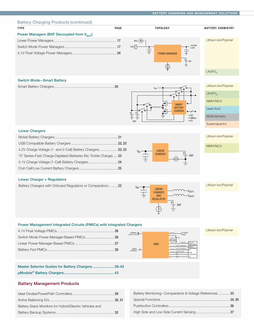
Power Managers (BAT Decoupled from VOUT)
Linear Power Managers ................................................................ 17
Switch Mode Power Managers ..................................................... 17
4.1V Float Voltage Power Managers ............................................. 24
Switch Mode – Smart Battery
Smart Battery Chargers ............................................................. 20
++
SMARTBATTERYCHARGER
• SPI• SMBus• I/O
VIN
BAT
Linear Chargers
Nickel Battery Chargers ................................................................ 21
USB Compatible Battery Chargers ............................................... 22, 23
4.2V Charge Voltage (1- and 2-Cell) Battery Chargers .................. 22, 23
“X” Series–Fast Charge Depleted Batteries (No Trickle Charge) ..... 23
4.1V Charge Voltage (1-Cell) Battery Chargers .............................. 24
Coin Cell/Low Current Battery Chargers ....................................... 25
+LINEARCHARGER
VIN
BATT
+
LINEARCHARGER
ANDREGULATOR
VIN
BAT
VOUT1
VOUT2
T
Lithium-Ion/Polymer
Lithium-Ion/Polymer
NiMH/NiCd
Lithium-Ion/Polymer
Linear Charger + Regulators
Battery Chargers with Onboard Regulators or Comparators ......... 22
Power Management Integrated Circuits (PMICs) with Integrated Chargers
4.1V Float Voltage PMICs .......................................................... 26
Switch Mode Power Manager-Based PMICs ............................. 26
Linear Power Manager-Based PMICs ........................................ 27
Battery-Fed PMICs .................................................................... 28
Battery Management Products
Ideal Diodes/PowerPath Controllers ........................................... 29
Active Balancing ICs .................................................................. 30, 31
Battery Stack Monitors for Hybrid/Electric Vehicles and
Battery Backup Systems ........................................................... 32
WALL
USB SYSTEMLOAD
+BAT
T
POWER MANAGER
Battery Monitoring – Comparators & Voltage References ............ 33
Special Functions ...................................................................... 34, 35
Pushbutton Controllers .............................................................. 36
High Side and Low Side Current Sensing .................................. 37
Battery Charging Products (continued)
BATTERY CHARGING SOLUTIONS2
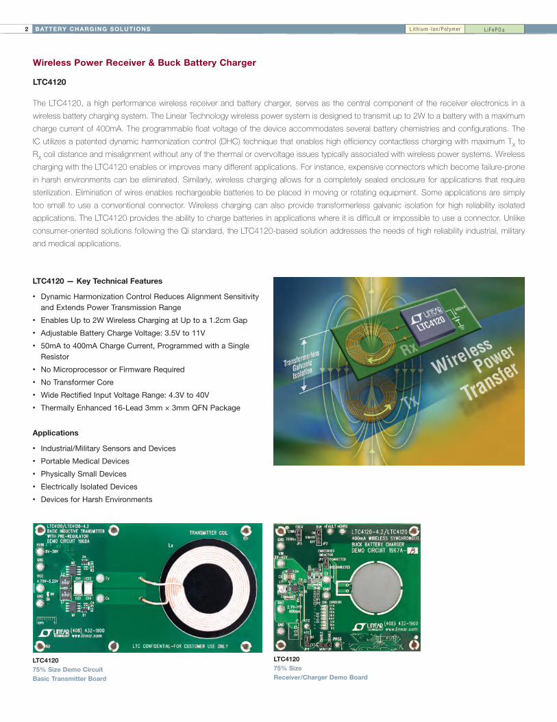
Wireless Power Receiver & Buck Battery Charger
LTC4120
The LTC4120, a high performance wireless receiver and battery charger, serves as the central component of the receiver electronics in a
wireless battery charging system. The Linear Technology wireless power system is designed to transmit up to 2W to a battery with a maximum
charge current of 400mA. The programmable float voltage of the device accommodates several battery chemistries and configurations. The
IC utilizes a patented dynamic harmonization control (DHC) technique that enables high efficiency contactless charging with maximum TX to
RX coil distance and misalignment without any of the thermal or overvoltage issues typically associated with wireless power systems. Wireless
charging with the LTC4120 enables or improves many different applications. For instance, expensive connectors which become failure-prone
in harsh environments can be eliminated. Similarly, wireless charging allows for a completely sealed enclosure for applications that require
sterilization. Elimination of wires enables rechargeable batteries to be placed in moving or rotating equipment. Some applications are simply
too small to use a conventional connector. Wireless charging can also provide transformerless galvanic isolation for high reliability isolated
applications. The LTC4120 provides the ability to charge batteries in applications where it is difficult or impossible to use a connector. Unlike
consumer-oriented solutions following the Qi standard, the LTC4120-based solution addresses the needs of high reliability industrial, military
and medical applications.
LTC4120 — Key Technical Features
• Dynamic Harmonization Control Reduces Alignment Sensitivity and Extends Power Transmission Range
• Enables Up to 2W Wireless Charging at Up to a 1.2cm Gap
• Adjustable Battery Charge Voltage: 3.5V to 11V
• 50mA to 400mA Charge Current, Programmed with a Single Resistor
• No Microprocessor or Firmware Required
• No Transformer Core
• Wide Rectified Input Voltage Range: 4.3V to 40V
• Thermally Enhanced 16-Lead 3mm × 3mm QFN Package
Applications
• Industrial/Military Sensors and Devices
• Portable Medical Devices
• Physically Small Devices
• Electrically Isolated Devices
• Devices for Harsh Environments
LTC4120 75% Size Receiver/Charger Demo Board
LTC4120 75% Size Demo Circuit Basic Transmitter Board
L i t h i um- I on /Po l yme r L i F ePO4
3BATTERY CHARGING SOLUTIONS
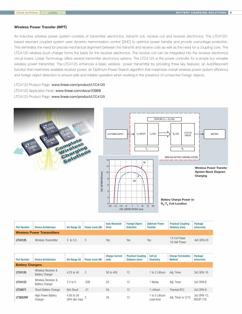
Wireless Power Transfer (WPT)
An inductive wireless power system consists of transmitter electronics, transmit coil, receive coil and receiver electronics. The LTC4120-
based resonant coupled system uses dynamic harmonization control (DHC) to optimize power transfer and provide overvoltage protection.
This eliminates the need for precise mechanical alignment between the transmit and receive coils as well as the need for a coupling core. The
LTC4120 wireless buck charger forms the basis for the receiver electronics. The receive coil can be integrated into the receiver electronics
circuit board. Linear Technology offers several transmitter electronics options. The LTC4125 is the power controller for a simple but versatile
wireless power transmitter. The LTC4125 enhances a basic wireless power transmitter by providing three key features: an AutoResonant
function that maximizes available receiver power, an Optimum Power Search algorithm that maximizes overall wireless power system efficiency
and foreign object detection to ensure safe and reliable operation when working in the presence of conductive foreign objects.
DC POWER SUPPLY BATTERY
COUPLING (TX + RX COIL)
TX RX
TX CIRCUIT LTC4120CIRCUIT
TX COIL RX COIL
WIRELESS BATTERY CHARGING SYSTEM
LTC4120 Product Page: www.linear.com/product/LTC4120
LTC4120 Application Note: www.linear.com/docs/43968
LTC4125 Product Page: www.linear.com/product/LTC4125
Wireless Power Transfer System Block Diagram Charging
Battery Charge Power vs RX-TX Coil Location
COIL CENTER OFFSET (mm)–20
0
COIL
SEP
ARAT
ION
(mm
)
12
10
8
6
4
2
14
10 15 20–10–15 –5
1W
2W
0 5
L i t h i um- I on /Po l yme r L i F ePO4
Part Number Device Architecture Vin Range (V) Power Level (W)Auto Resonant Drive
Foreign Object Detection
Optimum Power Transfer
Practical Coupling Distance (mm)
Package (mmxmm)
Wireless Power Transmitters
LTC4125 WirelessTransmitter 3to5.5 5 Yes Yes Yes13FullPower16HalfPower
4x5QFN-20
Part Number Device Architecture Vin Range (V) Power Level (W)Charge Current (mA)
Practical Coupling Distance (mm)
Cell (s) Chemistry
Charge Termination Method
Package (mmxmm)
Battery Chargers
LTC4120WirelessReceiver&BatteryCharger
4.25to40 2 50to400 12 1to3Lithium Adj.Timer 3x3QFN-16
LTC4123WirelessReceiver&BatteryCharger
2.2to5 .038 25 12 1Nickle Adj.Timer 2x2DFN-6
LTC4071 ShuntBatteryCharger N/AShunt .21 50 12 1Lithium ThermalNTC 2x3DFN-8
LT3652HVHighPowerBatteryCharger
4.95to34(40Vabsmax)
2 2A 121to5LithiumLeadAcid
Adj.TimerorC/103x3DFN-12,MSOP-12E

BATTERY CHARGING SOLUTIONS4
Switch Battery Chargers
LT3652HV: Power Tracking 2A Battery ChargerLT®3651: Monolithic 4A High Voltage Li-Ion Battery Charger
7.5V to 32V Single Cell 4A Charger 24V 5-Cell LiFePO4 Charger (18V at 1.5A) with C/10 Termination
Part Number
Maximum Charge Current (A)
VBAT Range (V)
Battery Chemistry
Number of Battery Cells (Series)
Input Voltage (V)
Integrated Power Transistor Synchronous
Charge Termination
Package (mmxmm)
Switch Mode Multi-Chemistry Buck (Step-Down) Battery Chargers
LTC4121 0.4 3.6to18Li-Ion,LiFePO4SLA
SLA,1-5LiFePO41-4Li-Ion
4.3to40 ~ – Timer 3x3QFN-16
LT1510 1 2.5to26NiMHNiCdSLALi-Ion
1-12Ni,SLA1-4Li-Ion
7to29 ~ –ExternalµCorLTC1729
SO-8,SSOP-16,SO-16
LT3652 2 3.3to14.4SLA,LiFePO4Li-Ion
SLA,1-4LiFePO41-3Li-Ion
4.9to32† ~ – TimerorC/10 3x3DFN-12,MSOP-12E
LT3652HV 2 3.3to18SLA,LiFePO4Li-Ion
SLA,1-5LiFePO41-4Li-Ion
4.9to34† ~ – TimerorC/103x3DFN-12,MSOP-12E
LT1769 2 2.5to26NiMHNiCdSLALi-Ion
1-12Ni,SLA1-4Li-Ion
7to29 ~ –ExternalµCorLTC1729
TSSOP-20,SSOP-28
LT1511 3 2.5to26NiMHNiCdSLALi-Ion
1-12Ni,SLA1-4Li-Ion
7to29 – –ExternalµCorLTC1729
SO-24
LTC4008 4 3to28NiMHNiCdSLALi-Ion
4-18Ni,SLA2-6Li-Ion
6to28 – ~ ExternalµC SSOP-20
LTC4009/-1*/-2 4 2to28NiMHNiCdSLALi-Ion
2-18Ni,1-4Li-Ion
6to28 – ~ ExternalµC 4x4QFN-20
LTC4012/-1*/-2/-3 4 2to28NiMHNiCdSLALi-Ion
2-18Ni,1-4Li-Ion
6to28 – ~ ExternalµC 4x4QFN-20
LT1505 8 2.5to23NiMHNiCdSLALi-Ion
1-12Ni,SLA1-4Li-Ion
6.7to26 – ~ ExternalµC SSOP-28
LTC1960 8 3.5to28NiMHNiCdSLALi-Ion
4-16Ni,SLA2-6Li-Ion
6to28 – ~ ExternalµC 5x7QFN-38,SSOP-36
LTC4015 20** upto35VLiFePO4SLALi-Ion
3/6/12SLA,1-9LiFePO41-8Li-Ion
4.5to35 – ~ Timer,C/X 5x7QFN-38
Switch Mode Li-Ion Buck Battery Chargers
LT1571 1.5 2.5to26 Li-Ion 1-2,Adj 6.2to27 ~ – ExternalµC SSOP-16,SSOP-28
LTC4001/-1* 2 4.2 Li-Ion 1 4to5.5 ~ ~ Timer 3x3QFN-16
LT3650-4.1/-4.2 2 4.1,4.2 Li-Ion 1 4.75to32†(40Max) ~ – Timer+C/10 3x3DFN-12,MSOP-12E
LT3650-8.2/-8.4 2 8.2,8.4 Li-Ion 2 9to32†(40Max) ~ – Timer+C/10 3x3DFN-12,MSOP-12E
LT3651-4.1/4.2 4 4.1,4.2 Li-Ion 1 4.8to32 ~ ~ Timer+C/10 5x6QFN-36
LT3651-8.2/8.4 4 8.2,8.4 Li-Ion 2 9to32 ~ ~ Timer+C/10 5x6QFN-36
LTC4002-4.2/-8.4 4 4.2,8.4 Li-Ion 1-2 4.7to22 – – Timer 3x3DFN-10,SO-8
LTC4006-2/-4/-6 4 5to16.8 Li-Ion 2-4 6to28 – ~ Timer SSOP-16
LTC4007/-1 4 7.5to16.8 Li-Ion 3-4 6to28 – ~ Timer SSOP-24
*4.1VCellVoltage,**Dependsonexternalcomponents,†MinimumStart-upVoltageis+3.3VAboveVBATMAX
Our step-down (buck) battery chargers enable high efficiency charging from a wide input voltage range for a variety of battery chemistries.
SWVIN
AC ADAPTERINPUT
24VDC AT 1AVIN_REG
VFB
BOOST
SENSE
BAT
NTC
1µF 10V 1N4148
127k
R110KB = 3380
10µF
20µH
10µF
5-Cell LiFePO4 PACK(18V FLOAT)
SYSTEMLOAD
+
44.2k
750k
MBRS340D3
MBRS340
51.1k
150k
665k
0.068
LT3652HV
SHDN
CHRG
FAULT
TIMERRT
TIMER
SW
BOOST
SENSE
BAT
ILIM RNG/SS GNDNTC
CLP CLN
1µF
100µF BATTERY
3.3µH
TOSYSTEMLOAD
24m54.9k
VIN
1N5819
VIN
22µF
+
LT3651-4.2
SHDNACPR FAULTCHRG
5.5V TO 32V
MBRS340
L i t h i um- I on /Po l yme r Mu l t i c hem i s t r yLead -Ac i dN iMH /N iCdL i F ePO4

5BATTERY CHARGING SOLUTIONS
Buck-Boost Battery Chargers
Our buck-boost battery chargers seamlessly charge a battery as its
voltage varies below, above or equal to the input voltage.
LTC4020: 55V Buck-Boost Multi-Chemistry Battery Charger with Maximum Power Point Control (MPPC)
Features
• Wide Voltage Range: 4.5V to 55V Input, Up to 55V Output (60V Absolute Maximums)
• Synchronous Buck-Boost DC/DC Controller
• Li-Ion and Lead-Acid Charge Algorithms
• ±0.5% Float Voltage Accuracy
• ±5% Charge Current Accuracy
• Instant-On for Heavily Discharged Batteries
• Ideal Diode Controller Provides Low Loss PowerPath when Input Power is Limited
• Input Voltage Regulation for High Impedance Input Supplies and Solar Panel Peak Power Operation
• Onboard Timer for Protection and Termination
• Bad Battery Detection with Auto-Reset
• NTC Input for Temperature Qualified Charging
• Low Profile (0.75mm) 38-Pin 5mm × 7mm QFN Package
Applications
• Portable Industrial and Medical Equipment
• Solar-Powered Systems
• Military Communications Equipment
• 12V to 24V Embedded Automotive Systems
DC2044A 30% of Actual Size Demo Circuit
Buck-Boost DC/DC Converter Controller with PowerPath Battery Charger Accepts Inputs from 4.5V to 55V and Produces Output Voltages Up to 55V
Part Number
Number of Battery Cells (Series)
Maximum Charge Current (A) VBAT Range (V)
Battery Chemistry
Input Voltage (V)
Integrated Power Transistor Synchronous Charge Termination
Package (mmxmm)
Switch Mode Buck-Boost (Step-Down/Step-Up) Battery Chargers
LT1512 1-12Ni 0.8 1.5to20NiCdNiMHSLA
2.4to29 ~ – ExternalµC SO-8
LT1513 1-12Ni 1.6 1.5to20NiCdNiMHSLA
2.4to29 ~ – ExternalµCDDPak,TO-220
LTC1980 1-2Li-Ion 4 2.85to10NiCdNiMHLi-Ion
4.1to12 – –ExternalµC,Timer(Li-Ion)
SSOP-24
LTC4110 *†Upto10Ni,1-4Li-Ion,Upto6SLA
4 3.5to18NiCdNiMHSLA,Li-Ion
6to19 – ~ Timer,C/10,SMBus 5x7QFN-38
LTC4020SLA,LiFePO4,Li-Ion,SLA
20+** 2.5to55LiFePO4,1-13Li-Ion
4.5to55 – ~ Timer,C/x 5x7QFN-38
*FlybackTopology,**Dependsonexternalcomponents,†SupercapacitorCompatible
RNTC
RSENSEB
RSENSEABUCK-BOOST
DC/DC CONVERTER PowerPath BATTERY CHARGERVIN VOUT
RCS
VIN (V)5
EFFI
CIEN
CY (%
) POWER (W
)
100 100
90
80
70
60
50
40
30
20
10
0
95
90
85
80
7510 15 20 3025
VOUT = 14V
EFFICIENCY
INPUT POWER
P(LOSS)
Maximum Power Efficiency vs VIN
L i t h i um- I on /Po l yme r Mu l t i c hem i s t r yLead -Ac i dN iMH /N iCdL i F ePO4
LTC4020
BATTERY CHARGING SOLUTIONS6
Solar Battery Charging ICs
Batteries are often paired with solar panels to provide energy storage for the inherently
intermittent power generation nature of solar panels. However, solar panels are non-ideal
power sources, and the operating point at which maximum power is generated depends
on many factors such as incident light (including any partial shading), temperature and
panel aging. When discussing solar panels and power, terms such as maximum power
point tracking (MPPT) and maximum power point control (MPPC) are often used.
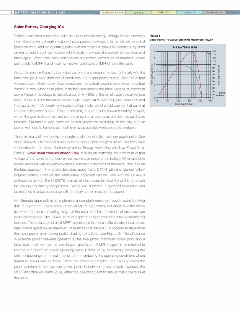
As can be seen in Figure 1, the output current of a solar panel varies nonlinearly with the
panel voltage. Under short-circuit conditions, the output power is zero since the output
voltage is zero. Under open-circuit conditions, the output power is zero since the output
current is zero. Most solar panel manufacturers specify the panel voltage at maximum
power (Vmp). This voltage is typically around 70 – 80% of the panel’s open circuit voltage
(Voc). In Figure 1 the maximum power is just under 140W with Vmp just under 32V and
Imp just under 4.5A. Ideally, any system using a solar panel would operate that panel at
its maximum power output. This is particularly true of a solar powered battery charger,
where the goal is to capture and store as much solar energy as possible, as quickly as
possible. Put another way, since we cannot predict the availability or intensity of solar
power, we need to harness as much energy as possible while energy is available.
There are many different ways to operate a solar panel at its maximum power point. One
of the simplest is to connect a battery to the solar panel through a diode. This technique
is described in the Linear Technology article “Energy Harvesting with Low Power Solar
Panels” (www.linear.com/solutions/1786). It relies on matching the maximum output
voltage of the panel to the relatively narrow voltage range of the battery. When available
power levels are very low (approximately less than a few tens of milliwatts), this may be
the best approach. The article describes using the LTC4071 with a single-cell Li-Ion/
polymer battery. However, the same basic approach can be used with the LTC4079
(without the diode). The LTC4079 dramatically increases the flexibility of this approach
by allowing any battery voltage from 1.2V to 60V. Therefore, a specified solar panel can
be matched to a battery or a specified battery can be matched to a panel.
An alternate approach is to implement a complete maximum power point tracking
(MPPT) algorithm. There are a variety of MPPT algorithms, but most have the ability
to sweep the entire operating range of the solar panel to determine where maximum
power is produced. The LT8490 is an example of an integrated circuit that performs this
function. The advantage of a full MPPT algorithm is that it can differentiate a local power
peak from a global power maximum. In multicell solar panels, it is possible to have more
than one power peak during partial shading conditions (see Figure 2). The difference
in available power between operating at the true global maximum power point and a
false local maximum can be very large. Typically, a full MPPT algorithm is required to
find the true maximum power operating point. It does so by periodically sweeping the
entire output range of the solar panel and remembering the operating conditions where
maximum power was achieved. When the sweep is complete, the circuitry forces the
panel to return to its maximum power point. In between these periodic sweeps, the
MPPT algorithm will continuously dither the operating point to ensure that it operates at
the peak.
7
6
5
4
3
2
1
0
1401301201101009080706050403020100
0V 10V 20V 30V 40V 50V
Pane
l Out
put C
urre
nt (A
)
Pane
l Out
put P
ower
(W)
Panel Output Voltage
CurrentPower
Pmp
Imp
Figure 1 Solar Panel I-V Curve Showing Maximum Power
L i t h i um- I on /Po l yme r Mu l t i c hem i s t r yLead -Ac i dN iMH /N iCdL i F ePO4
Full Sun 72-Cell 180W

7BATTERY CHARGING SOLUTIONS
7
6
5
4
3
2
1
0
1401301201101009080706050403020100
0V 10V 20V 30V 40V 50V
Pane
l Out
put C
urre
nt (A
)
Pane
l Out
put P
ower
(W)
Panel Output Voltage
CurrentPower
Figure 2 Partially Shaded Solar Panel Showing Multiple Power Maxima
An intermediate approach is something that Linear Technology calls maximum power
point control (MPPC). This technique takes advantage of the fact that the maximum
power voltage (VMP) of a solar panel does not, typically, vary much as the amount of
incident light changes (see "Solar Battery Charger Maintains High Efficiency in Low
Light" for more information). Therefore, a simple circuit can force the panel to operate at
a fixed voltage and approximate maximum power operation. A voltage divider is used to
measure the panel voltage and if the input voltage falls below the programmed level, the
load on the panel is reduced until it can maintain the programmed voltage level. Products
with this functionality include the LTC3105, LTC3129, LT3652(HV), LTC4000-1, and the
LTC4020. Depending on solar panel construction, shading conditions and incident light
levels, a full MPPT algorithm can extract considerably more power from a solar panel
than an MPPC algorithm. However, under some circumstances, the simplicity of an
MPPC approach may be a better choice.
A recent Linear Technology product introduction provides yet another technique to
extract maximum power from a limited source. The new approach is a blend of a full
MPPT algorithm and an MPPC function. The LTC4121 employs an MPPT algorithm that
compares a stored open-circuit input voltage measurement against the instantaneous
input voltage while charging. The LTC4121 automatically reduces the charge current if
the input voltage falls below the user-defined percentage of the open-circuit voltage. This
algorithm lets the LTC4121 optimize power transfer for a variety of different input sources
including first order temperature compensation of a solar panel. While this technique will
not differentiate between local and global maxima, it will adjust its operating conditions as
temperature varies, and it can accommodate a variety of solar panels without hardware
changes assuming the ratio of VMP to VOC remains approximately constant.
In summary, there are many different ways of operating a solar panel at its maximum
output operating condition. The panel can be connected to a battery (through a diode)
whose voltage range is close to the maximum power voltage of the panel. A full
MPPT algorithm, including periodic global sweeps to find the global maximum and a
continuous dither to remain at that maximum can be used (an example is the LT8490).
Other products implement an input voltage regulation technique (MPPC) to operate
a solar panel at a fixed operating voltage, including the energy harvesting switching
regulator devices LTC3105, LTC3129, the charge controller LTC4000-1, plus the battery
chargers LT3652(HV), and the LTC4020. Finally, the LTC4121 blends two approaches.
L i t h i um- I on /Po l yme r Mu l t i c hem i s t r yLead -Ac i dN iMH /N iCdL i F ePO4
Partially Shaded 72-Cell 180W Panel

BATTERY CHARGING SOLUTIONS8
Solar Battery Chargers: Switch Mode Buck / Buck-Boost, Linear and Shunt
Part Number
Maximum Charge Current (A)
VBAT Range (V)
Battery Chemistry
Number of Battery Cells (Series)
Input Voltage (V)
Integrated Power Transistor Synchronous
Charge Termination MPPx
Package (mmxmm)
Switch Mode Multi-Chemistry Buck and Buck-Boost (Step-Down/Step-Up) Solar Battery Chargers
LT3652 2 3.3to14.4SLA,LiFePO4Li-Ion
SLA,1-4LiFePO4,1-3Li-Ion
4.9to32† ~ – TimerorC/10 MPPC 3x3DFN-12,MSOP-12E
LT3652HV 2 3.3to18SLA,LiFePO4Li-Ion
SLA,1-5LiFePO4,1-4Li-Ion
4.9to34† ~ – TimerorC/10 MPPC 3x3DFN-12,MSOP-12E
LTC4121 400mA 3.5Vto18VSLALiFePO4Li-Ion
SLA1-5LiFePO4,1-4Li-Ion
4.4Vto40V ~ ~ Timer MPPT 3x3QFN-16
LTC4020 20+* 2.5Vto55VSLA,LiFePO4,Li-Ion
SLA,1-15LiFePO4,1-13Li-Ion
4.5Vto55V – ~ Timer,C/x MPPC 5x7QFN-38
LT8490 20+* 1.3Vto80V SLA,Li-Ion SLA,1-19Li-Ion 2.8Vto80V – ~ Timer,C/10 MPPT 5x7QFN-38,TSSOP-38
Linear Multi-Chemistry Solar Battery Chargers
LTC4079 250mA 1.2Vto60V SLALi-Ion,NiSLA,1-14Li-Ion,1-50Ni
2.7Vto60V ~ n/a C/10,Timer DVReg^ 3x3DFN-10
Shunt Solar Battery Chargers
LTC4070 50mA 2.7Vto4.2V Li-Ion 1,unlimited ~ – n/a n/a n/a 2x3DFN-8,MSOP-8
LTC4071 50mA^^ 2.7Vto4.2V Li-Ion 1,unlimited ~ – n/a n/a n/a 2x3DFN-8,MSOP-8
* Dependsonexternalcomponents^ Differentialvoltageregulation^^500mAwithexternalPFET
LT8490 - High Voltage, High Current Buck-Boost Battery Charge Controller with Maximum Power Point Tracking (MPPT)
Features• VIN Range: 6V to 80V
• VBAT Range: 1.3V to 80V
• Single Inductor Allows VIN Above, Below or Equal to VBAT
• Automatic MPPT for Solar Powered Charging
• Automatic Temperature Compensation
• No Software or Firmware Development Required
• Operation from Solar Panel or DC Supply
• Input and Output Current Monitor Pins
• Four Integrated Feedback Loops
• Synchronizable Fixed Frequency: 100kHz to 400kHz
• 64-Lead (7mm × 11mm × 0.75mm) QFN Package
Applications• Solar Powered Battery Chargers
• Multiple Types of Lead-Acid Battery Charging
• Li-Ion Battery Charger
• Battery Equipped Industrial or Portable Military Equipment
0.5s/DIV
VPANEL6V/DIV
IPANEL1.36A/DIV
BACK PAGE APPLICATION
PERTURB &OBSERVE
PERTURB &OBSERVE
FULL PANEL SCAN
LT8490
SOLAR PANEL
TG1 BOOST1
CSNINCSPINVIN
CSPOUTCSNOUTEXTVCC
AVDD
TEMPSENSEGATEVCCINTVCC
SW1 BG1 CSP CSN
STATUS FAULT
AVDD
BG2 SW2 BOOST2 TG2
GND
RECHARGABLEBATTERY
LOAD
THERMISTOR
+ –
AVDD
GATEVCC´
GATEVCC´ GATEVCC´
VBAT
Typical Application Circuit
Maximum Power Point Tracking
L i t h i um- I on /Po l yme r Mu l t i c hem i s t r yLead -Ac i dN iMH /N iCdL i F ePO4
LT8490
9BATTERY CHARGING SOLUTIONS
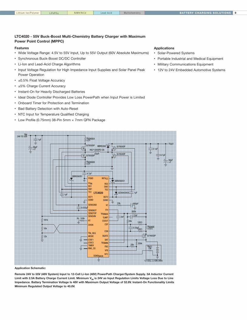
LTC4020 - 55V Buck-Boost Multi-Chemistry Battery Charger with Maximum Power Point Control (MPPC)
Features• Wide Voltage Range: 4.5V to 55V Input, Up to 55V Output (60V Absolute Maximums)
• Synchronous Buck-Boost DC/DC Controller
• Li-Ion and Lead-Acid Charge Algorithms
• Input Voltage Regulation for High Impedance Input Supplies and Solar Panel Peak Power Operation
• ±0.5% Float Voltage Accuracy
• ±5% Charge Current Accuracy
• Instant-On for Heavily Discharged Batteries
• Ideal Diode Controller Provides Low Loss PowerPath when Input Power is Limited
• Onboard Timer for Protection and Termination
• Bad Battery Detection with Auto-Reset
• NTC Input for Temperature Qualified Charging
• Low Profile (0.75mm) 38-Pin 5mm × 7mm QFN Package
Application Schematic:
Remote 24V to 55V (48V System) Input to 12-Cell Li-Ion (48V) PowerPath Charger/System Supply. 5A Inductor Current Limit with 2.5A Battery Charge Current Limit. Minimum VIN is 24V as Input Regulation Limits Voltage Loss Due to Line Impedance. Battery Termination Voltage Is 48V with Maximum Output Voltage of 52.8V. Instant-On Functionality Limits Minimum Regulated Output Voltage to 40.8V.
RSENSEA0.01
Si7850DP
Si7850DP
Si7850DP
Si7850DP
RSENSEB0.01
VIN24V TO 55V
LTC4020
SGNDBACK
PGND
RT, 100k
PVINBG1SW1TG1
BST1SGND
SENSGND
SENSBOTSENSTOPSENSVIN
RT
SHDN
VIN_REGMODE
TIMERRNG_SS
12-CELL Li-ION (48V)
INTVCC
BG2SW2TG2
BST2SGND
VC
ITH
VFBMAXILIMIT
CSOUT
CSP
CSN
BGATE
BATVFBMIN
FBG
VFB
NTC
56µF×2
1µF
191k
10k
12k
STAT1STAT2
1µF
SBR0560S14.7µF
33k
100Ω
RSENSE0.02Ω
Si7465DP
SBR0560S1
BZX84C6V2L
680pF
100Ω
365k
1.5nF2nF
0.33µF
356k20k
20k
1µF
RNTC10k
0.1µF
4.7µF
56µF×2
VOUT
IHLP-5050FD-5A
MBRS360
22µH
0.033µF
+
+
Applications• Solar-Powered Systems
• Portable Industrial and Medical Equipment
• Military Communications Equipment
• 12V to 24V Embedded Automotive Systems
L i t h i um- I on /Po l yme r Mu l t i c hem i s t r yLead -Ac i dN iMH /N iCdL i F ePO4
LTC4020

BATTERY CHARGING SOLUTIONS10
The Power and Flexibility of the LTC4000 / LTC4000-1
The LTC4000 is a high voltage controller and power manager which, when paired with an externally compensated DC/DC converter, becomes
a full-featured battery charger solution. The LTC4000 is capable of driving virtually any topology, including buck, boost, buck-boost, SEPIC and
flyback converters. Its intelligent PowerPath manager provides power to the system load when input power is available, enabling instant-on
operation even with a deeply discharged battery. A full-featured controller, the LTC4000 can charge a variety of battery types including lithium,
nickel and lead-acid based chemistries. Highly accurate charge current and float voltage, as well as onboard termination, ensure safe and
accurate charging.
Complete Solution: PowerPath™ Control & Termination, No Software
60V, 20A+ Battery Charging Controller
Features• Input/Output Voltage: 3V to 60V
• Charge Currents up to 20A+
• Input Ideal Diode for Low Loss Reverse Blocking and Load Sharing
• Programmable Input and Charge Current: ±1% Accuracy
• ±0.1% Accurate Programmable Float Voltage
• Programmable C/X or Timer-Based Charge Termination
• NTC Input for Temperature-Qualified Charging
• LTC4000-1 for Solar Panel Input Applications
TIME (HR:MIN:SEC)
0:0:0034
BATT
ERY
VOLT
AGE
(V)
37
40
43
46
0:30:00 1:00:00 1:30:00
49
52
–0.5
CHARGE CURRENT (A)
0.0
0.5
1.0
1.5
2.0
2.5
0:15:00 0:45:00 1:15:00
VBAT
IBAT
12S 2.2Ah Li-Ion Charge Curves
LTC4000 Buck-Boost Configuration Actual Size Demo Circuit
LTC4000
ITH
BAT
IGATE
BGATE
GND
Buck
Boost
Buck-Boost
SEPIC
FlybackVIN
3V to 60VSystem
I = Up to 20A+Status
MulticellBattery Stack
Turns AnySwitching Regulator
Into a Charger
DC/DC Converter
CHRG
VM
L i t h i um- I on /Po l yme r Mu l t i c hem i s t r yLead -Ac i dN iMH /N iCdL i F ePO4

11BATTERY CHARGING SOLUTIONS
LTC4000, LTC4000-1 Paired with Example Companion Switching Regulators
Topology LTC4000 + Switcher Input Voltage (V) Output Voltage (V) Charge Current (A) Battery
Lab-Tested LTC4000 Applications
Buck-Boost LTC3789 5-30 14.4 10 4CellLiFePO4
Buck-Boost LTC3789 6-36 14.6 5 4CellLiFePO4
Buck-Boost LTC3789 9-30 16.8 5 4CellLi-Ion
Buck-Boost LTC3789 10-27 24 4 12CellLead-Acid
Buck-Boost LTC3789 11-13 13.6 4 6CellLead-Acid
Buck-Boost LTC3789 11-13 38 2.5 18CellLead-Acid
Buck-Boost LT3790 6-60 14.5 6.5 4CellLiFePO4
Buck-Boost LT8705(+LTC4000-1) 15-60 29.4 6.25 7CellLi-Ion
Boost LTC3787 12-21 30 10 12CellLead-Acid
Boost LTC3862 19-24 42.5 5 11CellLi-Ion
Boost LTC3862 19-24 53.3 5 13CellLi-Ion
Boost LTC3786 6-21 21 5 5CellLi-Ion
Buck LT3845A 24-60 16.8 10 4CellLi-Ion
Buck LT3845A 15-60 10.8 10 3CellLiFePO4
Active Clamp Forward LTC3765,LTC3766 12-36 28 7 Lead-Acid
AC / DC NCP1012 110/220(AC) 14.4 0.33 4CellLiFePO4
Flyback LTC3805 18-72 4.2 2 1CellLi-Ion
BUCKCONTROLLER
VIN
VOUT
BAT
ITH
CLN
CL TMRC X GND BIAS
IN
CC IID IGATE CSP
CSN
BGATE
OFB
FBG
BFB
LTC4000
15V to 60V Buck 10A Charger for 3-Cell LiFePO4 12V to 21V Boost 10A Charger for 24V Lead-Acid
18V to 72V Flyback 2A Charger for 1-Cell Li-Ion 6V to 36V Buck-Boost 5A Charger for 4-Cell LiFePO4
BOOSTCONTROLLER
VIN VOUT
BAT
ITH
CLN
CL TMRC X GND BIAS
IN
CC IID IGATECSP
CSN
BGATE
OFB
FBG
BFB
LTC4000
VIN VOUT
BAT
ITH
CLN
CL TMRC X GND BIAS
IN
CC IID IGATECSP
CSN
BGATE
OFB
FBG
BFB
LTC4000
BUCK BOOSTCONTROLLER
•
• VSYSVIN
VCC
VCC
BAT
ITH
CL TMRC X GND BIAS
CC
CSP
CSN
BGATE
OFB
FBG
BFB
LTC4000
FLYBACKCONTROLLER
VOUT
VOUT CLN IID IGATEIN
L i t h i um- I on /Po l yme r Mu l t i c hem i s t r yLead -Ac i dN iMH /N iCdL i F ePO4

BATTERY CHARGING SOLUTIONS12
CC/CV Switching Regulators as Battery Chargers
In some battery powered applications, a system microcontroller already exists that can assume some, if not all, of the functions required to
safely manage the charging of the battery. In other cases, an integrated battery charger IC that meets the design requirements may not exist.
While the LTC4000 can help in many of these scenarios, a switching regulator with the ability to accurately control both its output voltage and
its output current may be sufficient. This section describes a variety of Linear Technology products that meet this requirement. Typically, these
products can be used in several different power topologies with extremely wide voltage operating ranges.
LT3790 - 60V Synchronous 4-Switch Buck-Boost Controller
Features• 4-Switch Single Inductor Architecture Allows VIN Above, Below or Equal to VOUT
• Synchronous Switching: Up to 98.5% Efficiency
• Wide VIN Range: 4.7V to 60V
• 2% Output Voltage Accuracy: 1.2V ≤ VOUT < 60V
• 6% Output Current Accuracy: 0V ≤ VOUT < 60V
• 38-Lead TSSOP Package
LT3790: 2.4A Buck-Boost 36V SLA Battery Charger
Part # Input Voltage (V) Output Voltage (V) Topology IOUT Accuracy VOUT Accuracy Charger Features Package (mm x mm)
CC/CV Switching Regulators as Battery Chargers
LT3741 6to36 Upto34 Buck ±6% ±1.5% - 4x4QFN-20,TSSOP-20
LT3763 6to60 Upto55 Buck ±6% ±1.5% C/10 TSSOP-28
LT3761 4.5to60 Upto80 Boost/SEPIC ±3% ±2% C/10 MSOP-16E
LT3796 6to100 Upto100 Boost/SEPIC ±3% ±2% C/10 TSSOP-28
LT3955 4.5Vto60 Upto80 Boost/SEPIC ±3% ±2% C/10 5x6QFN-36
LT3790 4.7to60 Upto60 Buck-Boost ±6% ±2% C/10 TSSOP-38
LT8705 2.8to80 Upto80 Buck-Boost ±9% ±1.8% - 5x7QFN-38,TSSOP-38
51
470nF
PVIN9V TO 58V
INTVCC
TG1
BG1
SNSP
SNSN
BST1
BST2
BG2
PGND
SW2TG2
RT
LT3790
SWI
RIN0.003
SHORT
IVINN
IVINP
1µFVIN
IVINMON
PWMOUT
ISMON
CLKOUT
EN/UVLO
OVLOINTVCC
200k
VREF
PWM
CTRLCHARGE CURRENT CONTROL
SGND
84.5k300kHz
D1, D2: BAT46WJL1: COILCRAFT SER2915L-103KM1-M4: RENESAS RJK0651DPBM5: NXP NX7002AKCIN2: NIPPON CHEMI-CON EMZA630ADA101MJA0GCOUT2: SUNCON 50HVT220M
VCSYNCSS
C/10
CCM
20k
51
INTVCC
57.6k
30.9k
499k
0.1µF
22nF
22nF
1µF
CIN2100µF63V
RSENSE0.004
ISP
ISN
FB
RBAT0.025
2.4ACHARGE
36VSLA BATTERYAGM TYPE41V FLOAT44V CHARGE AT 25°C
0.1µF
0.1µF
L1 10µH
4.7µF
M2
M1
M3
M4
D2D1
COUT2220µF50V
1.00M
30.1k402k
M52.2k
+
+
+
100k
L i t h i um- I on /Po l yme r Mu l t i c hem i s t r yLead -Ac i dN iMH /N iCdL i F ePO4 Supe r capac i t o r

13BATTERY CHARGING SOLUTIONS
CC/CV Switching Regulators as Battery Chargers (continued)
LT3796: 100V Constant-Current and Constant-Voltage Controller with Dual Current Sense
Features• Wide Input Voltage Range: 6V to 100V
• Current Monitoring Up to 100V
• High Side PMOS Disconnect and PWM Switch Driver
• Constant-Current and Constant-Voltage Regulation
• 28-Lead TSSOP Package
LT3796: SEPIC Sealed Lead-Acid (SLA) Battery Charger
LT3955: Solar Panel SEPIC Battery Charger
LT3955: 60VIN LED Converter with Internal PWM Generator
Features• Wide VIN Range: 4.5V to 60V
• Rail-to-Rail Current Sense Range: 0V to 80V
• Internal 80V/3.5A Switch
• Programmable PWM Dimming Signal Generator
• Constant Current (±3%) and Constant-Voltage (±2%) Regulation
• Accurate Analog Dimming
• 5mm x 6mm QFN-36 Package
R320k
CSPVSVIN CSN
RTVC FAULT
R62k
CTRL
FB2
CSOUT
PWM
TG
SYNC
VREF
OUTPUT CURRENTREPORTING
OPTIONAL INPUTCURRENT REPORTING
M1: VISHAY SILICONIX Si7456DPM2: VISHAY SUD19P06-60-E3M3: ZETEX ZXM61N03FL1: COILCRAFT MSD1260-333D1: ON SEMI MBRS260T3GD2: CENTRAL SEMI CMDZ15LR11: MURATA NCP18XH103F03RB
ISMON
SS
EN/UVLO
VREF
FB1
ISP
ISN
VMODE VMODE
FAULT
OUT
BAT
INTVCC INTVCC
GATE
SENSE
GND
CC10nF
L1A 33µHRSNS1 50mM2 IIN8V TO 40V
100V (TRANSIENT)
D1 RSNS2
250m
RT19.6k400kHz
RC499
C40.1µF
R4357k
R5100k
R2806k
R110k
D215V
C14.7µF50V
VIN
BAT
R1393.1k
RSNS15m
M3
M1
R740.2k
C310nF
CSOUT
R1230.1k
R1110kNTC
R1010.2k
•
C54.7µF
R849.9k
R1449.9k
L1B
C62.2µF100V
OUT VCHARGE = 14.6VVFLOAT = 13.5VAT 25°C
•
BAT
C210µF
+
R9113k
C70.1µF
INTVCC
INTVCCQ1
10µF25V
2.2µF50V
1µF
D1BATOUT
93.1k
30.1k
250m
10kNTC
BAT
10.5k
113k
49.9k
•VIN SW
LT3955
GNDKGNDVC RT
EN/UVLO
475k300k4.7µF50V
10nF
VIN
0.1µF100k
158k
499k 28.7k350kHz
24.9k
CTRL
DIM/SS
L1A, 33µH1:1
•
INTVCC
FB
ISP
SYNCPWMOUT
ISN
OUT
BAT
PGND
VMODE
M1: ZETEX ZXM61N03FL1: COILTRONICS DRQ127-330-RD1: ON SEMI MBRS260T3GQ1: ZETEX FMMT593
VREF
PWM
M1
+
WÜRTHSOLAR PANEL
VOC = 37.5VVMPP = 28V
23W
VCHARGE = 14.3VVFLOAT = 13.3VAT 25°C
L1B
VIN (V)20
0
CHAR
GING
CUR
RENT
(A)
24 28 32 36
1.2
1.0
0.6
0.8
0.4
0.2
40
LT3955: Battery Charger Waveforms
IBAT vs VIN
10ms/DIV
NOTE: WAVEFORMS SHOWN AS TESTED WITH 5Ω IN SERIES WITH 2mF CAPACITIVE LOAD.
VMODE10V/DIV
VBAT10V/DIV
IBAT0.33A/DIV
THE PART ISTURNED ON
CURRENT HITS C/10BATTERY IS HELD ATFLOAT VOLTAGE
L i t h i um- I on /Po l yme r Mu l t i c hem i s t r yLead -Ac i dN iMH /N iCdL i F ePO4 Supe r capac i t o r
LT3796

BATTERY CHARGING SOLUTIONS14
Battery-Fed (Charger-Fed) Systems
First generation USB system applications incorporated a current-
limited battery charger directly between the USB port and the battery
(see Figure 1). In this battery-fed topology, the battery directly powers
the system and the power available to the system from the USB can
be expressed as:
PSYS = IUSB•VBAT
because VBAT is the only voltage available to the system load. For
linear chargers, input current approximately equals charge current, so a
simple current limit is sufficient. Connecting the system load directly to
the battery eliminates the need for a load sharing diode. Disadvantages
of this topology include low efficiency, 500mA maximum charge
current from the USB, no system power when the battery voltage is low
(i.e., a dead or missing battery), and loss of nearly half of the available
power within the linear battery charger element as heat. Furthermore,
an additional resistor and signal transistor are required to increase
charge current when a wall adapter is present.
AC ADAPTER
USB
BAT
VIN
LINEARCC/CV
CHARGER
SYSTEMLOAD
+BAT
Figure 1: Simplified Battery-Fed Control Circuit
Linear PowerPath Power Managers
Second generation USB charging systems, commonly referred to as
PowerPath systems, develop an intermediate voltage between the USB
port and the battery (see Figure 2). In PowerPath systems, the USB port
supplies current to an intermediate voltage, VOUT, via a current-limited
switch. VOUT powers both the linear battery charger and the system load
with priority going to the system load. By decoupling the battery from the
system load, charging can be carried out opportunistically. PowerPath
systems also offer instant-on operation because the intermediate
voltage is available for system loads as soon as power is applied to
the circuit—this allows the end product to operate immediately when
plugged in, regardless of the battery’s state of charge. In a linear
Figure 2: Simplified Linear Power Manager Circuit
AC ADAPTER
USB
BAT
GATE
OPTIONAL:AUGMENTSINTERNALIDEAL DIODE
IDEALDIODE
VBUS OUT
LINEARCC/CV
CHARGER
+
LINEAR USB
CURRENT LIMIT SYSTEMLOAD
BAT
Tutorial: PowerPath Control
PowerPath system, nearly all of the 2.5W available from the USB port
is accessible to the system load provided the system load does not
exceed the input current limit. Furthermore, if the system requires more
power than is available from the input, an ideal diode also supplies
current to the load from the battery. Thus, a linear PowerPath system
offers significant advantages over a battery-fed system. But significant
power may still be lost, especially if the system load exceeds the input
current limit and the battery voltage is low, resulting in a large differential
between the input voltage and both the system voltage and the battery
voltage. An optional external PFET can reduce the ideal diode voltage
drop during heavy load conditions.

15BATTERY CHARGING SOLUTIONS
Switch Mode PowerPath Power Managers
Third generation USB charging systems feature a switch mode-based
topology (see Figure 3). This type of PowerPath device produces an
intermediate bus voltage from a USB-compliant step-down switching
regulator that regulates a small differential voltage above the battery
voltage. Linear Technology refers to this as Bat-Track™ adaptive output
control because the output voltage tracks the battery voltage. The
differential voltage between the battery and the system is large enough
to allow full charging through the linear charger, but small enough to
minimize power lost in the charger, thereby increasing system efficiency
and maximizing power available to the load. The switching average input
Figure 3: Simplified Switch Mode Power Manager Circuit
AC ADAPTER
USB
BAT
OUT
SW
GATE
OPTIONAL:AUGMENTSINTERNALIDEAL DIODE
IDEALDIODE
VBUS
+
SWITCHINGUSB CURRENT LIMIT
LINEARCC/CV
CHARGER
SYSTEMLOAD
BAT
current limit allows the use of nearly all of the 2.5W available from the
USB port, independent of operating conditions. By ensuring that the
Bat-Track regulation loop does not allow the output voltage to drop
below 3.5V (even with severely discharged batteries) this topology
also provides instant-on functionality. As in linear PowerPath systems,
an ideal diode allows the battery to supplement input power during
heavy load transients. An optional external PFET can reduce the ideal
diode voltage drop. This architecture is suitable for systems with large
(>1.5AHr) batteries and high (>2W) system power.

BATTERY CHARGING SOLUTIONS16
External High Voltage Switching Regulator Control
Several Linear Technology power manager ICs (both linear and switching) provide the ability to adaptively control the output of an external high
voltage switching regulator (see Figure 4). The WALL pin detects the presence of a high voltage supply (e.g., car battery, 12V wall adapter, FireWire
input) and enables Bat-Track adaptive output control via the buck regulator’s VC pin. Similar to a switching PowerPath system, the output of the
high voltage buck is regulated to a small differential voltage above the battery voltage with a minimum output voltage of approximately 3.5V. This
functionality maximizes charger efficiency while still allowing instant-on operation even when the battery is deeply discharged. Compared to the
traditional approach of converting a high voltage input to 5V to power the system,this technique can reduce system power dissipation by over 50%.
By choosing an LT3653 as the high voltage regulator, further system improvements can be made (see Figure 5). The LT3653 accurately controls its
maximum output current, which eliminates the potential for localized heating, reduces the required current rating of the power components and
provides a robust solution to withstand harsh overload and short-circuit conditions. In addition, the unique LT3653 architecture eliminates a
power PFET and output capacitor from the application schematic.
Figure 4: Simplified HV Switching Regulator Control Circuit Figure 5: Simplified LT3653 Control Circuit
BAT
USB
BAT
OUT
VBUS
ACPRWALLVC
VC HVOK
GATE
OPTIONAL:AUGMENTSINTERNALIDEAL DIODE
+
SYSTEMLOAD
VOUT
VIN ISENSE
SW
HV INPUT
CHARGER/POWER
MANAGER
LT3653
HIGH VOLTAGE
BUCK REGULATORHIGH VOLTAGE
BUCK REGULATOR
BAT
USB
BAT
OUT
VBUS
ACPRWALLVC
GATE
OPTIONAL:AUGMENTSINTERNALIDEAL DIODE
+
SYSTEMLOAD
FB
VIN SWHV INPUT
VC
CHARGER/POWER
MANAGER
HIGH VOLTAGE
BUCK REGULATOR
Attribute Battery-Fed Linear PowerPath Switch Mode PowerPath
Table 1: Comparison of USB-Compliant Battery Charging System Topologies
Size Small Moderate Larger
Complexity Simple Moderate MoreComplex
SolutionCost Low Moderate Higher
USBChargeCurrent Limitedto500mA Limitedto500mA 500mAandHigher(~2.3W)
AutonomousControlofInputPowerSources
No Yes Yes
Instant-OnOperation No Yes Yes
SystemLoadEfficiency(IBUS<USBLimit)
Good(VBAT/VBUS) Exceptional(>90%) Excellent(~90%)
SystemLoadEfficiency(ISYS>USBLimit) Good(VBAT/VBUS) Good(VBAT/VBUS) Excellent(~90%)
BatteryChargerEfficiency Good(VBAT/VBUS) Good(VBAT/VBUS) Excellent(~90%)
PowerDissipation High Moderate Low
Bat-TrackAdaptiveOutputControl/InterfacetoHVBuck
No Yes Yes

17BATTERY CHARGING SOLUTIONSL i t h i um- I on /Po l yme r
USB Power Managers: Battery Chargers with PowerPath Control
PowerPath products and architectures permit the load to be powered
from both VIN and the battery, enabling shorter charge time, instant-on
operation (even with a dead or missing battery) and more flexibility for
the portable device designer. Other key features include standalone
operation and thermal regulation.
High Voltage USB Power Manager with Bat-Track Adaptive Output Control
High Efficiency USB/Automotive Power Manager with Overvoltage Protection
LTC4098: Actual Size Demo Circuit
LTC4090: Actual Size Demo Circuit
HVINBOOST
IN
SW
TIMER
CLPROG GND PROG
HVOUT
HVPR
OUT
BAT
270pF 100k2k
5V WALLADAPTER
USB
HIGH (6V-36V)VOLTAGE INPUT
VC
59kRT
40.2k +
1kLTC4090
Li-Ion
SYSTEM
LOAD
LTC4090: USB Power Manager with 2A High Voltage Bat-Track Buck RegulatorLTC4098/-1: USB Power Manager with Overvoltage Protection
Part Number
Number of Battery Cells (Series)
Max Charge Current from Wall (A)
Max Charge Current from USB (mA)
Input Voltage (V)
Power Manager Topology
Charge Termination (Plus Indication) Ideal Diode RDS(ON)
Package (mm x mm)
USB Power Managers and Li-Ion/Polymer Linear Battery Chargers with PowerPath Control
LTC4055/-1* 1 1 500 4.35to5.5 Linear Timer 200mΩ 4x4QFN-16
LTC4089* 1 1.2 500 4.35to5.5USB,6-36,40MaxWall
Linear Timer+C/10 215mΩ,(<50mΩOpt.) 3x6DFN-22
LTC4089-5 1 1.2 500 4.35to5.5USB,6-36,40MaxWall
Linear Timer+C/10 215mΩ,(<50mΩOpt.) 3x6DFN-22
LTC4089-1*† /-3*^
1 1.2 500 4.35to5.5USB,6-36,40MaxWall
Linear Timer+C/10 215mΩ,(<50mΩOpt.) 3x6DFN-22
LTC4090* 1 1.2 500 4.35to5.5USB,6-38,60MaxWall
Linear Timer+C/10 215mΩ,(<50mΩOpt.) 3x6DFN-22
LTC4090-5 1 1.2 500 4.35to5.5USB,6-36,60MaxWall
Linear Timer+C/10 215mΩ,(50mΩOpt.) 3x6DFN-22
LTC4067 1 1.25 500 4.35to5.5,13OVP Linear Timer+C/10 200mΩ,(<50mΩOpt.) 3x4DFN-12
LTC4066/-1† 1 1.5 500 4.35to5.5,USB+WallInputs
Linear Timer+C/x 50mΩ 4x4QFN-24
LTC4085 /-1†/-3^/-4^
1 1.5 500 4.35to5.5,USB+WallInputs
Linear Timer+C/10 215mΩ,(<50mΩOpt.) 3x4DFN-14
LTC4088/-1/-2* 1 1.5 700 4.35to5.5 SwitchMode Timer+C/x 180mΩ,(<50mΩOpt.) 3x4DFN-14
LTC4098/-1*† 1 1.5 700 4.35to5.5USB,66OVP,Wall=5VAdapterorBuckHigh-V
SwitchMode Timer+C/x 180mΩ,(<50mΩOpt.) 3x4QFN-20
LTC4098-3.6*# 1 1.5 700 4.35to5.5USB,66OVP,Wall=5VAdapterorBuckHigh-V
SwitchMode Timer+C/x 180mΩ,(<50mΩOpt.) 3x4QFN-20
LTC4160/-1*†§ 1 1.5 700 4.35to5.5USB,66OVP SwitchMode Timer+C/x 180mΩ,(<50mΩOpt.) 3x4QFN-20
LTC4099*‡ 1 1.5 700 4.35to5.5USB,66OVP SwitchMode Timer+C/x 180mΩ,(<50mΩOpt.) 3x4QFN-20
LTC4155*§** 1 3.5 700 4.35to5.5USB,77OVP SwitchMode Timer+C/x 180mΩ 4x5QFN-28
LTC4156*§**# 1 3.5 700 4.35to5.5USB,77OVP SwitchMode Timer+C/x 180mΩ 4x5QFN-28
*Bat-TrackAdaptiveOutputControl,^3.95VCellVoltage,†4.1VCellVoltage,‡I2CControlled,Selectable4.1V/4.2VFloatVoltage,§USBOn-The-Go,#For1-cellLithiumIronPhosphate(LiFePO4)Batteries
LTC4098/LTC4098-1
VBUS
10µF
0.1µF 3.01k 1k
10µF
3.3µH
6.04k
VC WALL ACPR
INPUTAUTOMOTIVE,
FIREWIRE, ETC.
USB
TO µC
SYSTEMLOAD
CLPROG PROG GND
SW
BATSENS
OVGATE
OVSENS
D0-D2
VOUT
IDGATE
BAT
Li-Ion+
LT3480
3
HV
LTC4098/LTC4098-1
L i F ePO4

BATTERY CHARGING SOLUTIONS18
Supercapacitor/Capacitor Chargers and Backup Power ICs
Supercapacitors, capacitors with up to 100s of farads in value, are emerging as an alternative to batteries in applications where the importance
of power delivery trumps that of total energy storage. Supercapacitors have a number of advantages over batteries that make them a superior
solution when short-term high power is needed, such as in power ride-through applications. These advantages include lower effective series
resistance (ESR) and enhanced durability in the face of repeated charging.
Linear Technology offers a portfolio of linear, switching and switched-capacitor ICs designed to charge supercapacitors (also known as
ultracapacitors) and capacitors. These devices offer input or output current limiting, automatic cell balancing and a range of protection features
that make them uniquely suited to supercap charging.
LTC3350: High Current Supercapacitor Backup Controller and System Monitor
Features• High Efficiency Synchronous Step-Down CC/CV
Charging of One to Four Series Supercapacitors
• Step-Up Mode in Backup Provides Greater Utilization of Stored Energy in Supercapacitors
• 14-Bit ADC for Monitoring System Voltages/Currents, Capacitance and ESR
• Active Overvoltage Protection Shunts
• Internal Active Balancers—No Balance Resistors
• VIN: 4.5V to 35V, VCAP(n): Up to 5V per Capacitor, Charge/Backup Current: 10+A
• Programmable Input Current Limit Prioritizes System Load Over Capacitor Charge Current
• Dual Ideal Diode PowerPath Controller
• All NFET Charger Controller and PowerPath Controller
• Compact 38-Lead 5mm × 7mm QFN Package
Applications• High Current 12V Ride-Through UPS
• Servers/Mass Storage/High Availability Systems
Part Number TopologyInput Voltage (V)
VOUT VCAP (max) (V)
Storage Element
Quiescent Current (µA)
Charge Current
PowerPath Control
Automatic Balancing
Supercap Overvoltage Protection Package
Supercapacitor Chargers
LTC3225/-1 ChargePump-Boost 2.8-5.5 5.5 2SCap 20 150mA – ~*** ~ 2x3DFN-10
LTC3226 ChargePump-Boost+2LDOs
2.5-5.5 5.5 2SCap 20 360mA ~ ~*** ~ 3x3QFN-16
LTC3625/-1 SwitchingBuck&Boost 2.7-5.5 5.5 2SCap 23 1A* – ~*** ~ 3x4DFN-12
LTC4225 Linear 2.7-5.5 5.5 2SCap 20 1A – ~ ~ 3x3DFN-12MSOP-12
LTC3355 Buck+LDO+Charger+BoostBackup
3-20 5 1SCap 120 1A ~ ~ ~ 4x4QFN-29
LTC3110 Bi-DirBuck-Boost 1.71-5.25 5.5 1-2SCap 48 2A – ~ ~ 4x4QFN-20,TSSOP-24
LTC3128 Buck-Boost 1.73-5.5 5.5 1-2SCap 600 3A – ~ ~ 4x5QFN-20,TSSOP-24
LTC3350 BuckCharger,BoostBackup,Balancer+OVP,HealthMonitor
4.5-35 VIN 1-4SCap 4mA 10A+ ~ ~ ~ 5x7QFN-38
LTC3643 Bi-DirBoostCharger/BuckBackup
3-17 upto40V ElectricalCap
400 2A ~ n/a – 3x5QFN-24
LTC4040 BuckCharger+BoostBackup
3.5-5.5 5 Li-IonLifePO4
40 2.5A ~ n/a ~ 4x5QFN-24
*in2-inductorcircuit;500mAin1-inductorconfiguration **idealdiodeVINtoVOUT ***whilecharging
VIN
PFI OUTFB
OUTFET
TGATE
SW
BGATE
ICAPVCAPCAP4
CAP3
CAP2
CAP1
CAPRTN
CAPFB
INFET VOUTSP VOUTSN
ICHG (STEP-DOWN) IBACKUP
VCAP < VOUT(STEP-UP)
VCAP > VOUT(DIRECTCONNECT)
VOUT
10FVCAP
10F
10F
10F
I2C
VIN2V/DIV
VCAP2V/DIV
VOUT2V/DIV
400ms/DIVBACK PAGE APPLICATION CIRCUIT
0V
PBACKUP = 25W
VOUT
VCAP
VIN
High Current Supercapacitor Charger and Backup Supply
Backup Application
Supe r capac i t o r
LTC3350

19BATTERY CHARGING SOLUTIONS
LTC3128: 3A Monolithic Buck-Boost Supercapacitor Charger and Balancer with Accurate Input Current Limit
Features• ±2% Accurate Average Input Current Limit Programmable
Up to 3A
• Programmable Maximum Capacitor Voltage Limit
• Active Charge Balancing for Fast Charging of Unmatched Capacitors
• Charges Single or Stacked Capacitors
• VIN Range: 1.73V to 5.5V
• VOUT Range: 1.8V to 5.5V
• <2μA Quiescent Current from VOUT When Charged
• Output Disconnect in Shutdown: <1μA IQ Shutdown
• Power Good Comparator
• Power Failure Indicator
• Thermally Enhanced 20-Lead (4mm × 5mm × 0.75mm) QFN and 24-Lead TSSOP Package
Applications• Supercapacitor Based Backup Power
• Memory Backup
• Servers, RAID, RF Systems
• Industrial, Communications, Computing
Stacked Output Capacitors Charging Waveform
LTC3643: Bi-Directional Boost Charger/Buck Backup
LTC4040: Buck Charger and Boost Backup
Wide VIN (3A Programmed Input Current) to 4.2V
VOUT2.0V/DIV
MID2.0V/DIV
IIN2.0A/DIV
ILOAD2.0A/DIV
2 SECONDS/DIV
Supe r capac i t o r
1.7V TO 5.5VUP TO 3.0A
10µF
127k
3.3µH
C1: Murata DMF3Z5R5H474M3DTA0
301k
1.87M
C1C1b940mF
VOUT = 4.2V
3.57k
C1a940mF
10µF
SW1
RSENPRSENS
RUNPFIPFOPGOODMAXV
GND
FB
PROG
MIDLTC3128
SW2
VOUTPVOUTS
VIN
470pF

BATTERY CHARGING SOLUTIONS20
Smart Battery Chargers
Our smart battery chargers offer true plug-and-play operation,
independent of chemistry and cell configuration, built-in safety features,
reliable battery detection and automatic charge management.
17
11
6
10
7
9
8
15
16
13
14
20
5
4
24
23
1
3
2
21
22
18
19
12
3V TO 5.5V
6.04k10k54.9k
SMBCLK
5k
SMBDAT
SMBCLK
SMBDAT
DCIN
CHGEN
SMBALERT#
ACP SMART BATTERY
SYSTEM LOAD
1.13k
1.21k13.7k
SafetySignal
VDD
DCDIV
CHGEN
ACP
SMBALERT
SCL
SDA
THB
THA
ILIM
VLIM
IDC
DCIN
INFET
CLP
CLN
TGATE
BGATE
PGND
CSP
BAT
VSET
ITH
GND
LTC4100
LTC1760: Actual Size Demo Circuit
Dual Battery Charger/Selector System Architecture
SYSTEM LOAD
DCIN
SMBus (HOST)
SafetySignal 1
SMBus 1
SafetySignal 2
SMBus 2
LTC1760
SMART BATTERY
LTC1760: Dual Smart Battery System Manager
LTC4100: Smart Battery Charger Controller
SMBus Smart Battery Charger Controller
Part Number
Maximum Charge Current (A)
VBAT Range (V) Standalone
Serial Bus Type
Single or Dual Battery Pack
Float Voltage Accuracy
Safety Limits
AC Present Output
Charger On Status
Thermistor Interface Package
SMBus/SPI Battery Chargers (Controllers)
LTC4110 3 3.5to18 ~ SMBus1.1 Single* 0.5% – ~ ~ ~ 5x7QFN-38
LTC4100 4 3.5to26 ~ SMBus1.1 Single 0.8% ~ ~ ~ ~ SSOP-24
LTC4101 4 2.7to4.2 ~ SMBus1.1 Single 0.8% ~ ~ ~ ~ SSOP-24
LTC1760 4 3.5to28 ~ SMBus1.1 Dual 0.2% ~ ~ ~ ~ TSSOP-48
LTC1759 8 3to23 ~ SMBus1.0 Single 1% ~ – ~ ~ SSOP-36
LTC1960 8 6to28 – SPI Dual 0.8% – – – – 5x7QFN-38,SSOP-36
*Scalable
L i t h i um- I on /Po l yme r Mu l t i c hem i s t r yLead -Ac i dN iMH /N iCdL i F ePO4

21BATTERY CHARGING SOLUTIONS
NiMH and NiCd Battery Chargers
LTC4060: Standalone 2A Linear NiMH/NiCd Fast Battery Charger
LTC4060: Actual Size Demo Circuit
Our nickel battery chargers reduce component count, speed design
and allow fast, accurate and reliable charging of both NiMH and
NiCd cells.
2-Cell, 2A Standalone NiMH Fast Charger with Optional Thermistor and Charge Indicator
2A NiMH Battery Charger
VCC
VIN = 5V
GND
SHDN
CHRG
NTC
PROG
ARCT
SEL0
SEL1
ACP
SENSE
DRIVE
BAT
TIMER
CHEM
PAUSE
NTC
1.5nF
NiMHBATTERY
“CHARGE”
+
330Ω
698Ω
LTC4060
LTC4011: Actual Size Demo Circuit
LTC4011
LTC4011: High Efficiency 4A Standalone Switch Mode Battery Charger with Analog INFET Control
Part Number Topology
Number of Battery Cells* (Series)
Maximum Charge Current (A)
Input Voltage (V) Charge Termination
Integrated Power Transistor
End- of-Charge Signal
AC Present Signal
Thermistor Interface
Package (mm x mm)
NiMH/NiCd Battery Chargers – Standalone
LTC4060 Linear 1–4 2 4.5to10 -dV,t,V,T – ~ ~ ~ 3x5DFN-16,TSSOP-16
LTC4010 SynchronousStep-Down 1–16 4 4.5to34 -dV,dT/dt,T,t – ~ ~ ~ TSSOP-16E
LTC4011† SynchronousStep-Down 1–16 4 4.5to34 -dV,dT/dt,T,t – ~ ~ ~ TSSOP-20E
NiMH/NiCd Battery Chargers – Non-Standalone
LT1512 SEPIC 1–12 0.8 2.4to29 ExternalµC ~ – – – SO-8
LT1510 Step-Down 1–12 1 7to29 ExternalµC ~ – – – SO-8,SSOP-16,SO-16
LT1513 SEPIC 1–12 1.6 2.4to29 ExternalµC ~ – – – DDPak,TO-220
LT1769 Step-Down 1–12 2 7to29 ExternalµC ~ – – – TSSOP-20,SSOP-28
LT1511 Step-Down 1–12 3 7to29 ExternalµC ~ – – – SO-24
LTC4008 SynchronousStep-Down 4–14 4 6to28 ExternalµC – ~ ~ ~ SSOP-28
LTC4009/ -1/-2
SynchronousStep-Down 2–14 4 6to28 ExternalµC – ~ ~ – 4x4QFN-20
LTC4012/ -1/-2/-3†
SynchronousStep-Down 2–14 4 6to28 ExternalµC – ~ ~ – 4x4QFN-20
LT1505 SynchronousStep-Down 1–12 8 6.7to26 ExternalµC – ~ – – SSOP-28
LTC1960 Step-Down 4–16 8 6to28 ExternalµC,SPI – – – – 5x7QFN-38,SSOP-36
NiMH/NiCd Battery Chargers – Smart Chargers (SMBus)
LTC4110 SynchronousFlyback upto10 3 6to20 SmartBattery,ExternalµC – – ~ ~ 5x7QFN-38
LTC4100 Step-Down 1–13 4 6to28 SmartBattery,ExternalµC – – ~ ~ SSOP-24
LTC4101 Step-Down 2–3 4 6to28 SmartBattery,ExternalµC – – ~ ~ SSOP-24
LTC1759 Step-Down 1–13 8 11to24 SmartBattery,ExternalµC – – ~ ~ SSOP-36
LTC4079 Linear upto60V .25 2.7to60V Adj.TimerorC/10 ~ ~ – ~ 3x3DFN-10
*BasedonMaximumCellVoltageof1.8V,†IncludesPowerPathControl
N iMH /N iCd

BATTERY CHARGING SOLUTIONS22
Linear Li-Ion/Polymer Battery Chargers
We produce a comprehensive line of high performance battery chargers for
any rechargeable battery chemistry, including lithium-ion, lithium-polymer,
lead-acid and nickel-based. Our linear battery charger ICs are completely
autonomous in operation and offer many standard features for battery
safety and management, including on-chip battery preconditioning, status
signaling, thermal regulation and NTC thermistor interface.
LTC4065: Actual Size Demo Circuit
Standalone Li-Ion Charger
LTC4065/A: Standalone 750mA Li-Ion Battery Charger in 2x2 DFN
LTC4079: Actual Size Demo Circuit
Charging a Backup Battery
LTC4079: 60V, 250mA Linear Charger with Low Quiescent Current
+
IN1µF 1.54M
249k
10k3.01k
10k Li-Ion
BAT9V TO 60V 8.4V
EN FB
CHRGF BG
PROG
T
NTCBIAS
TIMER NTCGND
LTC4079
+
VCCR1510Ω
R2*1Ω
500mA
R32k
4.2VLi-IonBATTERY
VIN4.3V TO 5.5V
C11µF
LTC4065
CHRG
EN
BAT
PROG
GND
L i t h i um- I on /Po l yme r

23BATTERY CHARGING SOLUTIONS
Part NumberNumber of Battery Cells (Series)
Maximum Charge Current (A)
Input Voltage (V) Cell Type
Integrated Power Transistor
Charge Termination (Plus Indication)
Package (mm x mm)
Linear Li-Ion/Polymer Battery Chargers
LTC4054L 1 0.15 4.25to6.5 Li-Ion/Poly ~ C/10 ThinSOT™
LTC1734L 1 0.18 4.55to8 Li-Ion/Poly External ExternalμC ThinSOT
LTC4065L/X 1 0.25 3.75to5.5 Li-Ion/Poly ~ Timer+C/10 2x2DFN-6
LTC4079 14 0.25 2.7to60 Li-Ion/Poly,Ni,SLA ~ Timer 3x3DFN-10
LTC4080*/X* ¶ 1 0.5 3.75to5.5 Li-Ion/Poly ~ Timer+C/10 3x3DFN-10,MSOP-10E
LTC4081* 1 0.5 3.75to5.5 Li-Ion/Poly ~ Timer+C/10 3x3DFN-10
LTC4056* 1 0.7 4.5to6.5 Li-Ion/Poly External Timer ThinSOT
LTC1734 1 0.7 4.55to8 Li-Ion/Poly External ExternalμC ThinSOT
LTC4065* 1 0.75 3.75to5.5 Li-Ion/Poly ~ Timer+C/10 2x2DFN-6
LTC4065-4.4* 1 0.75 3.75to5.5 Li-Ion/Poly ~ Timer+C/10 2x2DFN-6
LTC4065A* 1 0.75 3.75to5.5 Li-Ion/Poly ~ Timer+C/10 2x2DFN-6
LTC4069* 1 0.75 3.75to5.5 Li-Ion/Poly ~ Timer+C/10 2x2DFN-6
LTC4069-4.4* 1 0.75 3.75to5.5 Li-Ion/Poly ~ Timer+C/10 2x2DFN-6
LTC4054*/X* ¶ 1 0.8 4.25to6.5 Li-Ion/Poly ~ C/10 ThinSOT
LTC4057* 1 0.8 4.25to6.5 Li-Ion/Poly ~ ExternalμC ThinSOT
LTC4059* 1 0.9 3.75to8 Li-Ion/Poly,Ni‡ ~ ExternalμC 2x2DFN-6
LTC4059A* 1 0.9 3.75to8 Li-Ion/Poly,Ni‡ ~ ExternalμC 2x2DFN-6
LTC4058*/X* ¶ 1 0.95 4.25to6.5 Li-Ion/Poly ~ C/10 3x3DFN-8
LTC4068*/X* ¶ 1 0.95 4.25to6.5 Li-Ion/Poly ~ C/x 3x3DFN-8
LTC4075*/X* ¶ 1 0.95 4.3to8 Li-Ion/Poly ~ C/x 3x3DFN-10
LTC4075HVX* ¶ 1 0.95 4.3to6,22max Li-Ion/Poly ~ C/x 3x3DFN-10
LTC4078*/X* ¶ 1 0.95 4.3to6,22max Li-Ion/Poly ~ C/x 3x3DFN-10
LTC4076* 1 0.95 4.3to8 Li-Ion/Poly ~ C/x 3x3DFN-10
LTC4077* 1 0.95 4.3to8 Li-Ion/Poly ~ C/10 3x3DFN-10
LTC3550-1* 1 0.95 4.3to8 Li-Ion/Poly ~ C/x 3x5DFN-16
LTC3550* 1 0.95 4.3to8 Li-Ion/Poly ~ C/x 3x5DFN-16
LTC3552-1* 1 0.95 4.25to8 Li-Ion/Poly ~ C/x 3x5DFN-16
LTC3552* 1 0.95 4.25to8 Li-Ion/Poly ~ C/x 3x5DFN-16
LTC4095* 1 0.95 4.3to5.5 Li-Ion/Poly ~ Timer+C/10 2x2DFN-8
LTC4064* 1 1.0 4.25to6.5 Li-Ion/Poly ~ Timer+C/10 MSOP-10E
LTC4061* 1 1.0 4.5to8 Li-Ion/Poly ~ Timer+C/x 3x3DFN-10
LTC4061-4.4* 1 1.0 4.5to8 Li-Ion/Poly ~ Timer+C/x 3x3DFN-10
LTC4062* † 1 1.0 4.3to8 Li-Ion/Poly ~ Timer+C/x 3x3DFN-10
LTC4063* § 1 1.0 4.3to8 Li-Ion/Poly ~ Timer+C/x 3x3DFN-10
LTC4096*/X* ¶ 1 1.2 4.25to5.5 Li-Ion/Poly ~ C/x 3x3DFN-10
LTC4097* 1 1.2 4.25to5.5 Li-Ion/Poly ~ C/x 2x3DFN-12
LTC4053* 1 1.25 4.25to6.5 Li-Ion/Poly ~ Timer+C/10 3x3DFN-10,MSOP-10E
LTC4052 # 1 1.3 4.5to10 Li-Ion/Poly ~ Timer+C/10 MSOP-8E
LTC1733 1 1.5 4.5to6.5 Li-Ion/Poly ~ Timer+C/10 MSOP-10E
LTC1731 1,2 1.5 4.5to12 Li-Ion/Poly External Timer+C/10 MSOP-8,S0-8
LTC1732 1,2 1.5 4.5to12 Li-Ion/Poly,Ni‡ External Timer+C/10 MSOP-10
*USB2.0Compatible,†OnboardComparator,‡Constant-CurrentMode(VoltageModeDisabled),§OnboardLDO,¶“X”(NoTrickleCharge)VersionsUsefulwhentheSystemLoadExceedstheTrickleChargeCurrentatVeryLowBatteryVoltages#PulseCharger
Linear Li-Ion/Polymer Battery Chargers (continued)
L i t h i um- I on /Po l yme r
BATTERY CHARGING SOLUTIONS24
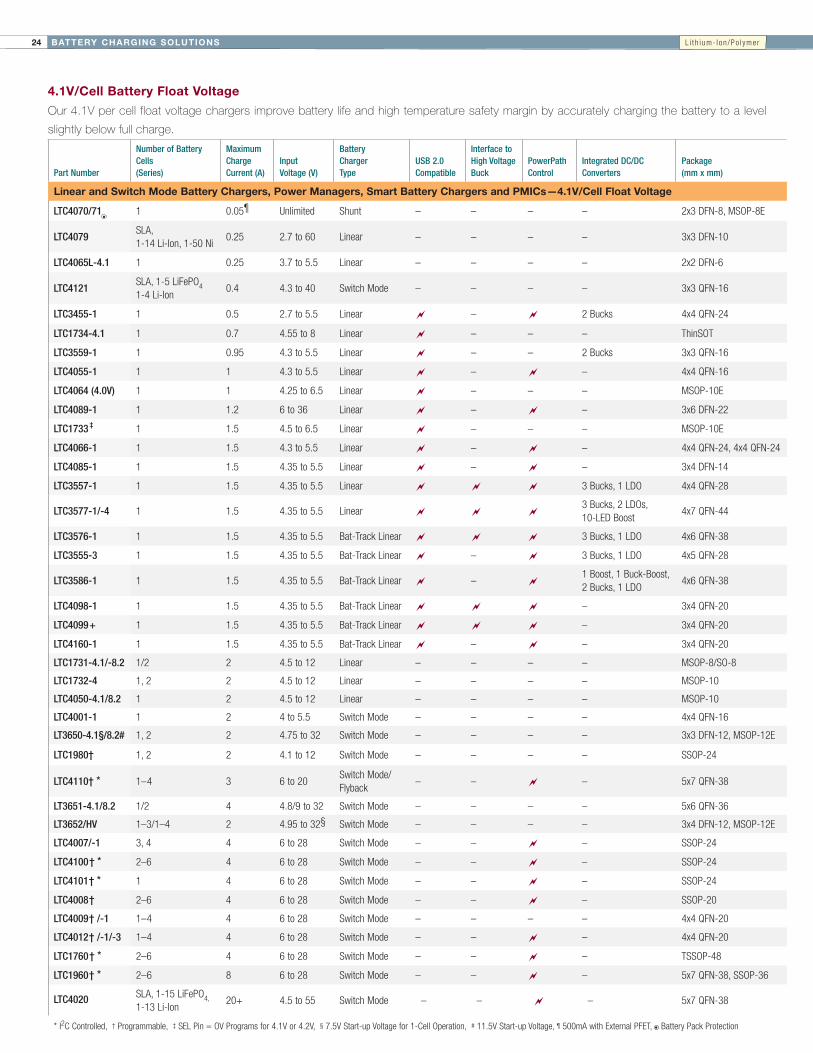
4.1V/Cell Battery Float Voltage
Our 4.1V per cell float voltage chargers improve battery life and high temperature safety margin by accurately charging the battery to a level
slightly below full charge.
Part Number
Number of Battery Cells (Series)
Maximum Charge Current (A)
Input Voltage (V)
Battery Charger Type
USB 2.0 Compatible
Interface to High Voltage Buck
PowerPath Control
Integrated DC/DC Converters
Package (mm x mm)
Linear and Switch Mode Battery Chargers, Power Managers, Smart Battery Chargers and PMICs—4.1V/Cell Float Voltage
LTC4070/71 1 0.05¶ Unlimited Shunt – – – – 2x3DFN-8,MSOP-8E
LTC4079SLA,1-14Li-Ion,1-50Ni
0.25 2.7to60 Linear – – – – 3x3DFN-10
LTC4065L-4.1 1 0.25 3.7to5.5 Linear – – – – 2x2DFN-6
LTC4121SLA,1-5LiFePO41-4Li-Ion
0.4 4.3to40 SwitchMode – – – – 3x3QFN-16
LTC3455-1 1 0.5 2.7to5.5 Linear ~ – ~ 2Bucks 4x4QFN-24
LTC1734-4.1 1 0.7 4.55to8 Linear ~ – – – ThinSOT
LTC3559-1 1 0.95 4.3to5.5 Linear ~ – – 2Bucks 3x3QFN-16
LTC4055-1 1 1 4.3to5.5 Linear ~ – ~ – 4x4QFN-16
LTC4064 (4.0V) 1 1 4.25to6.5 Linear ~ – – – MSOP-10E
LTC4089-1 1 1.2 6to36 Linear ~ – ~ – 3x6DFN-22
LTC1733 ‡ 1 1.5 4.5to6.5 Linear ~ – – – MSOP-10E
LTC4066-1 1 1.5 4.3to5.5 Linear ~ – ~ – 4x4QFN-24,4x4QFN-24
LTC4085-1 1 1.5 4.35to5.5 Linear ~ – ~ – 3x4DFN-14
LTC3557-1 1 1.5 4.35to5.5 Linear ~ ~ ~ 3Bucks,1LDO 4x4QFN-28
LTC3577-1/-4 1 1.5 4.35to5.5 Linear ~ ~ ~3Bucks,2LDOs,10-LEDBoost
4x7QFN-44
LTC3576-1 1 1.5 4.35to5.5 Bat-TrackLinear ~ ~ ~ 3Bucks,1LDO 4x6QFN-38
LTC3555-3 1 1.5 4.35to5.5 Bat-TrackLinear ~ – ~ 3Bucks,1LDO 4x5QFN-28
LTC3586-1 1 1.5 4.35to5.5 Bat-TrackLinear ~ – ~1Boost,1Buck-Boost,2Bucks,1LDO
4x6QFN-38
LTC4098-1 1 1.5 4.35to5.5 Bat-TrackLinear ~ ~ ~ – 3x4QFN-20
LTC4099+ 1 1.5 4.35to5.5 Bat-TrackLinear ~ ~ ~ – 3x4QFN-20
LTC4160-1 1 1.5 4.35to5.5 Bat-TrackLinear ~ – ~ – 3x4QFN-20
LTC1731-4.1/-8.2 1/2 2 4.5to12 Linear – – – – MSOP-8/SO-8
LTC1732-4 1,2 2 4.5to12 Linear – – – – MSOP-10
LTC4050-4.1/8.2 1 2 4.5to12 Linear – – – – MSOP-10
LTC4001-1 1 2 4to5.5 SwitchMode – – – – 4x4QFN-16
LT3650-4.1§/8.2# 1,2 2 4.75to32 SwitchMode – – – – 3x3DFN-12,MSOP-12E
LTC1980† 1,2 2 4.1to12 SwitchMode – – – – SSOP-24
LTC4110† * 1–4 3 6to20SwitchMode/Flyback
– – ~ – 5x7QFN-38
LT3651-4.1/8.2 1/2 4 4.8/9to32 SwitchMode – – – – 5x6QFN-36
LT3652/HV 1–3/1–4 2 4.95to32§ SwitchMode – – – – 3x4DFN-12,MSOP-12E
LTC4007/-1 3,4 4 6to28 SwitchMode – – ~ – SSOP-24
LTC4100† * 2–6 4 6to28 SwitchMode – – ~ – SSOP-24
LTC4101† * 1 4 6to28 SwitchMode – – ~ – SSOP-24
LTC4008† 2–6 4 6to28 SwitchMode – – ~ – SSOP-20
LTC4009† /-1 1–4 4 6to28 SwitchMode – – – – 4x4QFN-20
LTC4012† /-1/-3 1–4 4 6to28 SwitchMode – – ~ – 4x4QFN-20
LTC1760† * 2–6 4 6to28 SwitchMode – – ~ – TSSOP-48
LTC1960† * 2–6 8 6to28 SwitchMode – – ~ – 5x7QFN-38,SSOP-36
LTC4020 SLA,1-15LiFePO4,1-13Li-Ion
20+ 4.5to55 SwitchMode – – ~ – 5x7QFN-38
*I2CControlled,†Programmable,‡SELPin=OVProgramsfor4.1Vor4.2V,§7.5VStart-upVoltagefor1-CellOperation,#11.5VStart-upVoltage,¶500mAwithExternalPFET,BatteryPackProtection
L i t h i um- I on /Po l yme r

25BATTERY CHARGING SOLUTIONS
Low Current/Coin Cell Battery Chargers
Our coin cell battery chargers enable highly accurate charging of low
capacity, charge-sensitive coin cells used in thin, compact devices
such as Bluetooth headsets and hearing aids.
LTC4054L: Actual Size Demo Circuit
LT4351
VCC
1µF
VIN4.5V TO 6.5V
BAT
PROG
GND
LTC4054L-4.2
Li-Ion
COIN
CELL
90mA
1.69k
LTC4065L Complete Charge Cycle
+
VCCR1510
100mA
R32k
4.2VLi-IonBATTERY
VIN4.3V TO 5.5V
CHRG
EN
BAT
PROG
GND
LTC4065L
TIME (HOURS)0
CHAR
GE C
URRE
NT (m
A)
30
90
100
110
1 2 2.5
10
70
50
20
80
0
60
40
4.3
3.5
4.1
3.3
3.9
3.7
0.5 1.5 3 3.5 4 4.5
CONSTANTCURRENT CONSTANT
VOLTAGE
CHRGTRANSITION
CHARGETERMINATION
VCC = 5VRPROG = 2k
LTC4054L Complete Charge Cycle
TIME (HOURS)0
CHAR
GE
CURR
ENT
(mA)
100
90
80
70
60
50
40
30
20
10
0
BATTER
Y VOLTA
GE (V
)
4.4
4.3
4.2
4.1
4.0
3.9
3.8
3.7
3.6
3.5
3.40.5 1.0 1.25 2.250.25 0.75 1.5 1.75 2.0
CONSTANTCURRENT
CONSTANTVOLTAGE
VCC = 5VJA = 130°C/W
RPROG = 1.69kTA = 25°C
O
LTC4054L: 150mA Standalone Li-Ion Battery Charger for Coin Cells
LTC4065L: 250mA Standalone Linear Li-Ion Battery Charger in 2mm x 2mm DFN
90mA Li-Ion Coin Cell Charger Standalone Li-Ion Charger
BATTER
Y VOLTA
GE (V
)
Part NumberCharge Current Range (mA)
Input Voltage (V)
Battery Charger Type Standalone
Charge Termination (Plus Indication)
Thermal Regulation
Integrated Power Transistor
Package (mmxmm)
Coin Cell Li-Ion Battery Chargers
LTC4070 0.001-50† Unlimited Shunt ~ ~ – ~2x3DFN-8MSOP-8E
LTC4071 0.001-50 Unlimited Shunt ~ ~ – ~2x3DFN-8MSOP-8E
LTC4054L 10-150 4.25to6.5 Linear ~ C/10 ~ ~ ThinSOT
LTC1734L 10-180 4.55to8 Linear – – – External ThinSOT
LTC4079 10-250 2.7to60 Linear – Timer – – 3x3DFN-10
LTC4065L/LX* 15-250 3.75to5.5 Linear ~ Timer+C/10 ~ ~ 2x2DFN-6
LTC4059/A 90-900 3.75to8 Linear – – ~ ~ 2x2DFN-6
*“X”(NoTrickleCharge)VersionsUsefulwhentheSystemLoadExceedstheTrickleChargeCurrentatVeryLowBatteryVoltages,†500mAwithextPFET
L i t h i um- I on /Po l yme r
BATTERY CHARGING SOLUTIONS26
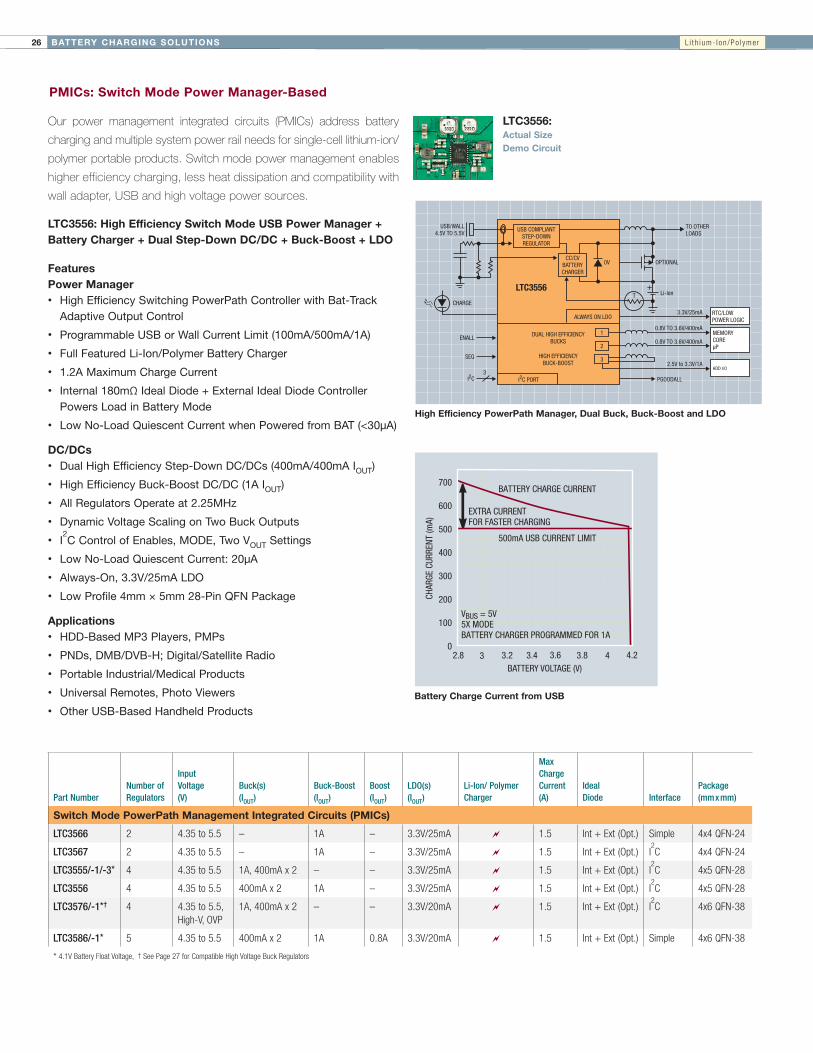
PMICs: Switch Mode Power Manager-Based
Our power management integrated circuits (PMICs) address battery
charging and multiple system power rail needs for single-cell lithium-ion/
polymer portable products. Switch mode power management enables
higher efficiency charging, less heat dissipation and compatibility with
wall adapter, USB and high voltage power sources.
LTC3556: High Efficiency Switch Mode USB Power Manager + Battery Charger + Dual Step-Down DC/DC + Buck-Boost + LDO
FeaturesPower Manager• High Efficiency Switching PowerPath Controller with Bat-Track
Adaptive Output Control
• Programmable USB or Wall Current Limit (100mA/500mA/1A)
• Full Featured Li-Ion/Polymer Battery Charger
• 1.2A Maximum Charge Current
• Internal 180mΩ Ideal Diode + External Ideal Diode Controller Powers Load in Battery Mode
• Low No-Load Quiescent Current when Powered from BAT (<30µA)
DC/DCs• Dual High Efficiency Step-Down DC/DCs (400mA/400mA IOUT)
• High Efficiency Buck-Boost DC/DC (1A IOUT)
• All Regulators Operate at 2.25MHz
• Dynamic Voltage Scaling on Two Buck Outputs
• I2C Control of Enables, MODE, Two VOUT Settings
• Low No-Load Quiescent Current: 20µA
• Always-On, 3.3V/25mA LDO
• Low Profile 4mm × 5mm 28-Pin QFN Package
Applications• HDD-Based MP3 Players, PMPs
• PNDs, DMB/DVB-H; Digital/Satellite Radio
• Portable Industrial/Medical Products
• Universal Remotes, Photo Viewers
• Other USB-Based Handheld Products
BATTERY VOLTAGE (V)2.8
0
CHAR
GE C
URRE
NT (m
A)
200
3.2 3.6 3.8
100
700
400
500
600
300
3 3.4 4 4.2
BATTERY CHARGE CURRENT
500mA USB CURRENT LIMIT
EXTRA CURRENT FOR FASTER CHARGING
VBUS = 5V5X MODEBATTERY CHARGER PROGRAMMED FOR 1A
High Efficiency PowerPath Manager, Dual Buck, Buck-Boost and LDO
LTC3556: Actual Size Demo Circuit
Li-Ion
PGOODALL
0.8V TO 3.6V/400mA
3.3V/25mA
2.5V to 3.3V/1A
0.8V TO 3.6V/400mA
OPTIONAL0V
T
TO OTHERLOADS
+
DUAL HIGH EFFICIENCYBUCKS
HIGH EFFICIENCYBUCK-BOOST
I2C PORT
ALWAYS ON LDO
MEMORYCORE µP
RTC/LOWPOWER LOGIC
USB/WALL4.5V TO 5.5V
CHARGE
I2C
USB COMPLIANTSTEP-DOWNREGULATOR
CC/CVBATTERYCHARGER
SEQ
ENALL
3
1
2
3
LTC3556
HDD I/O
Battery Charge Current from USB
Part NumberNumber of Regulators
Input Voltage (V)
Buck(s) (IOUT)
Buck-Boost (IOUT)
Boost (IOUT)
LDO(s) (IOUT)
Li-Ion/ Polymer Charger
Max Charge Current (A)
Ideal Diode Interface
Package (mmxmm)
Switch Mode PowerPath Management Integrated Circuits (PMICs)
LTC3566 2 4.35to5.5 – 1A – 3.3V/25mA ~ 1.5 Int+Ext(Opt.) Simple 4x4QFN-24
LTC3567 2 4.35to5.5 – 1A – 3.3V/25mA ~ 1.5 Int+Ext(Opt.) I2C 4x4QFN-24
LTC3555/-1/-3* 4 4.35to5.5 1A,400mAx2 – – 3.3V/25mA ~ 1.5 Int+Ext(Opt.) I2C 4x5QFN-28
LTC3556 4 4.35to5.5 400mAx2 1A – 3.3V/25mA ~ 1.5 Int+Ext(Opt.) I2C 4x5QFN-28
LTC3576/-1*† 4 4.35to5.5,High-V,OVP
1A,400mAx2 – – 3.3V/20mA ~ 1.5 Int+Ext(Opt.) I2C 4x6QFN-38
LTC3586/-1* 5 4.35to5.5 400mAx2 1A 0.8A 3.3V/20mA ~ 1.5 Int+Ext(Opt.) Simple 4x6QFN-38
*4.1VBatteryFloatVoltage,†SeePage27forCompatibleHighVoltageBuckRegulators
L i t h i um- I on /Po l yme r

27BATTERY CHARGING SOLUTIONS
PMICs: Linear Power Manager-Based
Our power management integrated circuits (PMICs) address battery
charging and multiple system power rail needs in single-cell lithium-ion/
polymer portable products. Linear power management allows seamless
transition and manages power flow between input power sources such
as a wall adapter, USB port, lithium battery and the system load.
LTC3577/-1: Highly Integrated 6-Channel PMIC
LTC3577: Actual Size, Complete Solution
Features• Full Featured Li-Ion Charger/
PowerPath Controller with Instant-On Operation
• High Temperature Battery Voltage Reduction Improves Safety and Reliability
• 1.5A Maximum Charge Current with Thermal Limiting
• Pushbutton On/Off Control with System Reset
• Dual 150mA Current Limited LDOs
• Triple Adjustable High Efficiency Step-Down Switching Regulators (600mA, 400mA, 400mA IOUT)
• 200mΩ Internal Ideal Diode Plus External Ideal Diode Controller Provides Low Loss PowerPath from Battery
• Bat-Track Control for External HV Buck DC/DCs
• I2C Adjustable SW Slew Rates for EMI Reduction
• Overvoltage Protection for USB (VBUS)/Wall Input
• Integrated 40V Series LED Driver with 60dB Brightness and Gradation Control via I2C
• Small 4mm × 7mm 44-Pin QFN Package
Applications• PNDs, DMB/DVB-H; Digital/
Satellite Radio
• Portable Industrial/Medical Products
• Universal Remotes, Photo Viewers
• Other USB-Based Handheld Products
+
100mA/500mA1000mA
HV SUPPLY
USB
CHARGE
PB
2
CC/CVCHARGER
LED BACKLIGHT WITH DIGITALLYCONTROLLED DIMMING
DUAL LDOREGULATORS
TRIPLE HIGH EFFICIENCYSTEP-DOWN SWITCHING
REGULATORS WITHPUSHBUTTON CONTROL
HIGH VOLTAGEBUCK DC/DC
0V
SINGLE CELLLi-Ion
UP TO 10 LEDBOOST
VOUT
0.8V to 3.6V/600mA
0.8V to 3.6V/150mA0.8V to 3.6V/150mA
0.8V to 3.6V/400mA0.8V to 3.6V/400mA
NTC
I2C PORT
OVERVOLTAGEPROTECTION
OPTIONAL
LTC3577/LTC3577-1
Solution Size = 22mm x 15mm
USB Plus HV Input Charger and Multichannel PMIC
LED Driver Efficiency (10 LEDs)
ILED (mA)
0
EFFI
CIEN
CY (%
)
70
75
80
20
65
60
505 10 15
55
90
85
3.8V3.6V3.4V3.2V
VOUT
Part NumberNumber of Regulators
Input Voltage (V) Buck(s) (IOUT) LDO(s)
Li-Ion/ Polymer Charger
Max Charge Current PowerPath
Ideal Diode Interface
Package (mmxmm)
Linear PowerPath Management Integrated Circuits (PMICs)
LTC3553 2 4.35to5.5 200mA 150mA ~ 500mA ~ ~ – 3x3QFN-20
LTC3554 2 4.35to5.5 200mAx2 – ~ 500mA ~ ~ – 3x3QFN-20
LTC3455 3 2.7to5.5,USB+WallInputs 400mA,600mA‡ Controller ~ 500mA ~ – – 4x4QFN-24
LTC3557/-1§ 4 2.7to5.5,USB,High-VBat-Track(*) 600mA,400mAx2 3.3V/25mA ~ 1.5A ~ Int+Ext(Opt.) – 4x4QFN-28
LTC3577/-3
LTC3577-1/-4§ 6# 2.7to5.5,USB,High-VBat-Track(*),OVP 800mA,500mAx2 2x150mA ~ 1.5A ~ Int+Ext(Opt.) – 4x7QFN-44
LTC3677-3¶ 6 2.7to5.5,USB,High-VBat-Track(*),OVP 800mA,500mAx2 2x150mA ~ 1.5A ~ Int+Ext(Opt.) – 4x7QFN-44
*SeeTableBelowforCompatibleHighVoltageBuckRegulators,†Includes50mAHotSwap™Controller,‡MaybeIncreasedto1AwithAdditionalComponents,§4.1VBatteryFloatVoltage,#Includes10-LEDBoost,¶NoLEDDriver
Part NumberInput Voltage, Maximum (V) Efficiency (%) ISW/IOUT (A)
Switching Frequency
Reference Voltage (V)
Inductor (µH)
Output Capacitor (µF)
Quiescent Current ISD (µA)
Package (mmxmm)
*High Voltage Buck Regulators (Compatible with LTC3557, LTC3576 and LTC3577)
LT3505 3.6-36,40 >85 1.75/1.2 300k-3MHz 0.78 6.8 10-Ceramic 2mA <23x3DFN-8,MSOP-8E
LT3480 3.6-38,60 >85 3/2 200k-2MHz 0.79 4.7 22-Ceramic 70µA <13x3DFN-10,MSOP-10E
LT3481 3.6-34,36 >85 3.2/2 300k-2.8MHz 1.26 4.7 22-Ceramic 50µA <13x3DFN-10,MSOP-10E
LT3653 7.5-30,60 >85 2/1.2 1.5MHz n/a 4.7 10-Ceramic 2.8mA n/a 2x3DFN-8
L i t h i um- I on /Po l yme r

BATTERY CHARGING SOLUTIONS28
PMICs: Linear Battery Charger (Battery-Fed)
Our power management integrated circuits (PMICs) address battery
charging and multiple system power rail needs in single-cell lithium
portable products. A high level of integration is offered in a small
footprint for a compact total solution size and ease-of-use.
LTC3558: Linear USB Battery Charger with Buck-Boost and Buck Regulators
FeaturesPower Manager• Standalone USB Charger
• Up to 950mA Charge Current Programmable via Single Resistor
• HPWR Input Selects 20% or 100% of Programmed Charge Current
• NTC Input for Temperature Qualified Charging
• Internal Timer Termination
• Bad Battery Detection
Switching Regulators• 400mA Output Current per Regulator
• 2.25MHz Constant Frequency Operation
• Power Saving Burst Mode® Operation
• Low Profile 3mm × 3mm 20-Pin QFN Package
Applications• PNDs, DMB/DVB-H; Digital/Satellite Radio
• SD/Flash-Based MP3 Players
• Portable Industrial/Medical Products
• Universal Remotes, Photo Viewers
• Other USB-Based Handheld Products
• Low Power Handheld Applications
LTC3558: Actual Size Complete Solution
Buck-Boost Regulator Efficiency vs Input Voltage
USB Charger Plus Buck Regulator and Buck-Boost Regulator
VCC
NTC
PROG
SUSP
HPWR
EN1
4.7µH10µF
649k
324k
10pF
22µF
10pF
GNDEXPOSED
PAD
1µF
2.2µH
1.74k
EN2
MODE
BATUSB (4.3V TO 5.5V)
DIGITALCONTROL
PVIN1
PVIN2
SW1
FB1SWAB2
SWCD2VOUT2
FB2
VC2
1.2V AT 400mA
SINGLELi-lon CELL(2.7V TO 4.2V)
105k
324k
15k
121k
3.3V AT 400mA
330pF
33pF
+
CHRG
10µF
LTC3558
Solution Size = 12mm x 11mm
PVIN2 (V)
EFFI
CIEN
CY (%
)
60
85
90
95
100
75
55
80
50
70
65
ILOAD = 100mA
ILOAD = 400mA
ILOAD = 10mAILOAD = 1mA
VOUT = 3.3V
Burst ModeOPERATIONPWM MODE
2.7 3.0 3.3 3.6 3.9 4.2
Part NumberNumber of Regulators
Maximum Charge Current (mA) Input Voltage (V)
Buck(s) (IOUT)
Buck-Boost(s) (IOUT)
Li-Ion/Polymer Charger
PowerPath Topology
Package (mmxmm)
Power Management Integrated Circuits (PMICs), Charger-Fed
LTC4080 1 500 2.7-4.5 300mA – ~ – 3x3DFN-10,MSOP-10E
LTC4081 1 500 2.7-4.5 300mA – ~ – 3x3DFN-10
LTC3550/-1 1 950 2.5-5.5 600mA – ~ – 3x5DFN-16
LTC3552/-1 2 950 2.5-5.5 400mA/800mA – ~ – 3x5DFN-16
LTC3558 2 950 3.0-4.2 400mA 400mA ~ – 3x3QFN-20
LTC3559 2 950 3.0-4.2 400mAx2 – ~ – 3x3QFN-16
L i t h i um- I on /Po l yme r

29BATTERY MANAGEMENT SOLUTIONS
Ideal Diodes/PowerPath Controllers
Our ideal diode devices provide a low loss, near “ideal” diode function. They feature much lower forward
voltage drop and reverse leakage current than conventional Schottky diodes. This reduces power loss and
eases thermal management while extending battery run time.
LTC4413: Actual Size Demo Circuit
VFWD (mV)
0
I OUT
(mA)
1000
1500
400
500
0100 200 300
2000
LTC4413
1N5817
LTC4413 vs 1N5817 SchottkyMonolithic Dual Ideal Diode
ENBA
GND
ENBB
470k
VCC
INATO LOAD
STAT IS HIGH WHENBAT IS SUPPLYINGLOAD CURRENTWALL
ADAPTER(0V TO 5.5V)
OUTA
INB OUTB
STAT
CONTROL CIRCUIT
LTC4413
LTC4352: MOSFET Diode-OR Controller
5V Ideal Diode Circuit with Input Undervoltage and Overvoltage Protection
Part NumberIdeal Diode
External MOSFET
Integrated MOSFET
Maximum Current (A)
Input Voltage (V)
Forward Voltage (mV)
Forward ON Resistance
Reverse Leakage Current (µA)
Supply Current (µA)
Package (mmxmm)
P-Channel PowerPath/Ideal Diode Controllers
LTC4411 Single P-Channel ~ 1 2.6to5.5 28 140mΩ 1 35 ThinSOT
LTC4412 Single P-Channel – 2* 2.5to28 20 Controller 3 13 ThinSOT
LTC4412HV Single P-Channel – 2* 2.5to36 20 Controller 3 13 ThinSOT
LTC4413/-1† Dual P-Channel ~ 2.6 2.5to5.5 28 100mΩ 1 20 3x3DFN-10
LTC4413-2† Dual P-Channel ~ 2.6 2.5to5.5,13,OVP 28 100mΩ 1 20 3x3DFN-10
LTC4414 Single P-Channel – 5-75* 3to36 22 Controller 3 33 MSOP-8
LTC4415 Dual P-Channel ~ 4 1.7to5.5 15 50mΩ 1 44 3x5DFN-16,MSOP-16
LTC4416/-1 Dual P-Channel – 5-75* 3.6to36 22 Controller 3 70 MSOP-10
LTC4417 Triple P-Channel – 5-75* 2.5to36 * Controller n/a 28 4x4QFN-24,SSOP-24
*DependsonMOSFETSelection,†HighSpeedVersion
Part No.Ideal Diode
External MOSFET
Maximum Current (A)
Input Voltage (V)
Package (mmxmm)
N-Channel Power PowerPath/Ideal Diode Controllers
LTC4352 Single N-Channel ≥5* 0to18 3x3DFN-12,MSOP-12
LTC4357 Single N-Channel ≥5* 9to80 2x3DFN-6,MSOP-8
LTC4358 SingleN-Channel(Internal)
5 9to26.5 4x3DFN-14,TSSOP-16
LTC4359 Single N-Channel ≥5* 4to80 2x3DFN-6,MSOP-8
LTC1473 Dual N-Channel ≥5* 4.75to30 SSOP-16
LTC1473L Dual N-Channel ≥5* 2.8to9 SSOP-16
LTC2952† Dual N-Channel ≥5* 2.7to28 TSSOP-20,4x4QFN-20
LTC4353 Dual N-Channel ≥5* 0to18 4x3DFN-16,MSOP-16
LTC4371 Dual N-Channel ≥5*–4.5to>–100(Floating)
3x3DFN-10,MSOP-10
LTC4355 Dual N-Channel ≥5* 9to80 4x3DFN-14,SOIC-16
LTC1479 Triple N-Channel ≥5* 6to28 SSOP-36
*DependsonMOSFETSelection,†PushbuttonPowerPathControllerwithSupervisor
LTC4413: Dual 2.6A, 2.5V to 5.5V Ideal Diodes in 3mm x 3mm DFN
BAT
UV
LTC4352
FAULT
STATUS
VCC
31.6k1%
1k1%
3.09k1%
TO LOAD5V
Q2Si7336ADP
Q1Si7336ADP
0.1 µF
CPOVIN SOURCE GATEFAULT
D1: GREEN LED LN1351CD2: RED LED LN1261CAL
MOSFET ONOUT
0.15µF
REVGND
5V
D2 D1
5V
1k 1k
OV

BATTERY MANAGEMENT SOLUTIONS30
Active Balancing ICs
Emerging electric vehicles (EV) and plug-in hybrid vehicles (PHEV) are demanding longer usable run time from their battery stacks. These stacks
of batteries are typically made of battery modules, each with as many as 12 Li-Ion cells stacked in series, offering a 400V battery module. As
the battery run time defines the very feasibility of these vehicles, maximizing battery capacity is of primary importance. Batteries can always
be made larger to improve driving range but this increases the weight, size and cost of the vehicle. So the goal for automotive EV designers
is to find ways to make the existing battery run longer. One effective method is to employ active balancing. Because EV batteries are stacked
in series, the lowest capacity cell will limit the entire battery stack’s run time. Ideally, the batteries would be perfectly matched, but this is often
not the case, and generally gets worse as the batteries age. Passive energy balancing offers no improved run time, as it dissipates the extra
energy of the higher capacity batteries as heat to match the lowest one. Conversely, high efficiency active balancing redistributes the charge
from the stronger cells (higher voltage) to the weaker cells. This enables the weaker cells to continue to supply the load during stack discharge,
extending the vehicle’s range. It may also be beneficial to have onboard diagnostics for each cell within these modules to monitor temperature,
voltage (state of charge) and internal impedance both for safety and long term reliability.
Practical Example• Big batteries are expensive—they all degrade over time and lose capacity
• Low cost/refurbished cells have greater capacity mismatch
• Increasing stack capacity with mismatched cells done in 2 ways:
– Use bigger batteries (solution cost ~ $1–$2 per A-hr per cell)
– Use active balancing
• LTC3300-1 solution cost ~ $2–$3 per cell, depending on IBAL
• LT8584 solution cost ~ $3.50–$4.50 per cell, depending on IBAL
• Example, adding 10A-hrs of capacity costs:
– Bigger batteries: ~ $10–$20 per cell
– Active balancing: ~ $2–$3 per cell
• Active balancing maximizes run time and allows fastest charge rates
LTC3300-1/-2 - High Efficiency/Addressable Bidirectional Multicell Battery Balancer
The LTC3300-1 is a fault-protected controller IC for transformer-based bidirectional active balancing of multicell battery stacks. All associated
gate drive circuitry, precision current sensing, fault detection circuitry and a robust serial interface with built-in watchdog timer are integrated.
Each LTC3300-1 can balance up to six series-connected battery cells with an input common mode voltage up to 36V. Charge from any
selected cell can be transferred at high efficiency to or from 12 or more adjacent cells.
LTC3300-1 Offers• Highest energy recovery (max run time)
• 92% transfer efficiency, bidirectional operation
• Fastest balancing time (min charge time)
• Up to 10A charge/discharge current, external power switches
• Numerous safety features
• Cost efficiency – 6-cell integration
Features• Bidirectional Synchronous Flyback Balancing of Up to Six Li-Ion or
LiFePO4 Cells in Series
• Up to 10A Balancing Current (Set by External Components)
• Bidirectional Architecture Minimizes Balancing Time and Power Dissipation
• Up to 92% Charge Transfer Efficiency
• Stackable Architecture Enables >1000V Systems
• Integrates Seamlessly with LTC6804-X Family of Battery Cell Monitor ICs
• Uses Simple 2-Winding Transformers
• 1MHz Daisy-Chainable Serial Interface with 4-Bit CRC Packet Error Checking
• High Noise Margin Serial Communication
• Numerous Fault Protection Features
• 48-Lead Exposed Pad QFN & LQFP Packages
Applications• Electric Vehicles/Plug-in HEVs
• High Power UPS/Grid Energy Storage Systems
• General Purpose Multicell Battery Stacks

31BATTERY MANAGEMENT SOLUTIONS
LT8584 - 2.5A Monolithic Active Cell Balancer with Telemetry Interface
The LT8584 is a monolithic flyback DC/DC designed to actively balance high voltage stacks of batteries. The high efficiency of a switching
regulator significantly increases the achievable balancing current while reducing heat generation. The LT8584 includes an integrated 6A/50V
power switch, reducing the complexity of the application circuit. The device runs completely off the cell it is discharging, eliminating complicated
biasing schemes. The LT8584 provides system telemetry including current, temperature and cell voltage when used with the LTC680x family of
battery monitors.
LT8584 Offers • High level of integration
• Numerous safety features, additional system monitoring MUX
– Measure IBAL for calculating “IR Drop Compensation,” “Coulomb tracking”
– Measure internal reference for BMS self-testing per channel
• Simple to use: no additional software required for “Simple Mode” operation
• High energy recovery
– 82% charge transfer efficiency
• Fast balancing time
– 2.5A discharge current, internal power switch
Features • 2.5A Typical Average Cell Discharge Current
• Integrated 6A/50V Power Switch
• Integrates Seamlessly with LTC680x Family
• Selectable Current and Temperature Monitors
• Ultralow Quiescent Current in Shutdown
• Engineered for ISO 26262 Compliant Systems
• Isolated Balancing:
– Can Return Charge to Top of Stack
– Can Return Charge to Any Combination of Cells in Stack
– Can Return Charge to 12V Battery for Alternator Replacement
• Can Be Paralleled for Greater Discharge Capability
Applications• Active Battery Stack Balancing
• Electric and Hybrid Electric Vehicles
• Failsafe Power Supplies
• Energy Storage Systems
LTC3305 Lead-Acid Battery Balancer
The LTC3305 balances up to four lead-acid batteries connected in
series. All voltage monitoring, gate drive and fault detection circuitry
is integrated. The LTC3305 is designed for standalone operation and
does not require any external control circuitry.
Summary of Features: LTC3305• Single IC Balances Up to Four 12V Lead-Acid Batteries in Series
• All NFET Design
• Stackable to Balance Larger Series Battery Packs
• Standalone Operation Requires no External μP or Control Circuitry
• Balancing Current Limited by External PTC Thermistor
• Continuous Mode and Timer Mode
• Programmable UV and OV Fault Thresholds
• Programmable Termination Time and Termination Voltage
• 38-Lead TSSOP and 7mm × 7mm 48-Lead LQFP Packages

BATTERY MANAGEMENT SOLUTIONS32
TEMPERATURE (°C)–45
TME
(mV)
2.5
1.5
0.5
–0.5
–1.5
2.0
1.0
0
–1.0
–2.0
–2.55 55–20 30 80 105
High Voltage Battery Stack Monitors for Battery Management Systems
Applications• Passenger Automobiles (EV, HEV)
• Electric Bicycles (Motorcycles, Scooters)
• Commercial Vehicles (Buses, Trains)
• Industrial Equipment (Forklifts, Trucks)
• Marine (Boats, Submarines)
• Mil/Aero (Planes, Satellites, Unmanned Vehicles)
• Energy Storage Systems
LTC6804: Next Generation Battery Stack Monitor
Features• Measures Up to 12 Battery Cells in Series
• Stackable Architecture Supports 100s of Cells
• Built-in isoSPI™ Interface
• Delta-Sigma ADC With Frequency Programmable 3rd Order Noise Filter
• 1.2mV Maximum Total Measurement Error
• 240µs to Measure All Cells in a System
• Synchronized Voltage and Current Measurement
• Engineered for ISO26262 Compliant Systems
• Passive Cell Balancing with Programmable Timer
• General Purpose I/O for Digital or Analog Inputs, also Configurable for I2C Interface
• 4μA Sleep Mode Supply Current
• 48-Lead SSOP Package
LTC6820: Noise Immune, Isolated, Bidirectional SPI Communications (isoSPI)
Features• Supports LTC6804 High Voltage Battery Monitor
• 1Mbps Isolated SPI Using Standard Transformers
• Bidirectional Interface Over a Single Twisted Pair
• Supports Cable Lengths Up to 100 Meters
• Configurable for High Noise Immunity or Low Power
• Ultralow, 2.5μA Idle Current
• Interfaces with 1.8V to 5V Logic
• 16-Lead QFN and MSOP Packages
Part Number
Primary Function
Measurement Error Max Multichip Interface Package Comments
LTC6804-1 12CellMeasurements
0.10% isoSPI,Daisy-Chain SSOP-483rdGeneration:HighNoiseImmunityHighAccuracy,240µsecConversion
LTC6804-2 12CellMeasurements
0.10% isoSPI,Addressable SSOP-483rdGeneration:HighNoiseImmunityHighAccuracy,240µsecConversion
LTC6803-1/3 12CellMeasurements
0.25% SPI,Daisy-Chain SSOP-442ndGeneration:HighNoiseImmunity,0µAshutdown
LTC6803-2/4 12CellMeasurements
0.25% SPI,Addressable SSOP-442ndGeneration:HighNoiseImmunity,0µAshutdown
LTC6802-1 12CellMeasurements
0.25% SPI,Daisy-Chain SSOP-441stGeneration:SupersededbytheLTC6804andLTC6803fornewdesigns
LTC6802-2 12CellMeasurements
0.25% SPI,Addressable SSOP-441stGeneration:SupersededbytheLTC6804andLTC6803fornewdesigns
LTC6801 12CellFaultMonitor
0.50%DifferentialClockSignals,Daisy-Chain
SSOP-36StandaloneUndervoltage/OvervoltageMonitor,ProvidesRedundancy
Stackable BMS Architecture
Isolated 2-Wire Communication Data Rate vs Cable Length
Total Measurement Error vs Temperature
IP
120Ω
100 METERSTWISTED PAIR
LTC6820MSTRMOSIMISOSCKCS
IM
MASTERµC
SDOSDI
SCKCS
IP
120Ω
LTC6820MSTR
MOSI
MISO
SCK
CS
IM
REMOTESLAVE IC
SDISDOSCK
CS
CABLE LENGTH (METERS)
10
DATA
RAT
E (M
bps)
0.2
0.4
0.6
0.8
1.2
10 100
1.0
CAT-5 ASSUMED
LTC680412s1pLi-Ion
LTC6804
LTC6804
+
–
NominalCellVoltage=3.3V

33BATTERY MANAGEMENT SOLUTIONS
Battery Monitoring Devices
By combining a voltage reference with a comparator, it is easy to
create accurate battery monitors. Linear Technology offers a number of
combination devices with very low power and high accuracy voltage
references. These products are available in many pin configurations to
support a wide range of designs with minimum package footprint and
pin count.
LT6109: High Side Current Sense Amplifier with Reference and Dual Comparator
The LT6109 is an ideal choice for monitoring batteries. It includes a precision high side current sense amplifier, a dual comparator for monitoring current and/or voltage, and a voltage reference. As shown, it is simple to implement battery fault protection. In this example, the comparators monitor for overcurrent and undervoltage conditions. If either fault is detected, the battery will be immediately disconnected from the load. The latching comparator outputs ensure the battery stays disconnected until an outside source resets the LT6109 comparator output.
Overcurrent and Undervoltage Battery Fault Protection
Part Number DescriptionSupply Voltage (V)
Prop Delay (µs) Typ
Hysteresis (mV)
Supply Current (µA)
Package (mm x mm)
Comparator and Reference Combinations
LT6700 DualComparatorswith400mVReference 1.4to18 18 6.5 10 SOT-23,2x3DFN-6
LT6700HV 36VInput/OutputDualComparatorsandReference 1.4to18 18 6.5 10 SOT-23
LT6700MP DualComparatorsandReferencefor–55°Cto150°C 1.4to18 18 6.5 10 2x3DFN-6
LT6703 SingleComparatorandInternalReference 1.4to18 18 6.5 10 SOT-23,2x2DFN-3
LT6703HV 36VInput/OutputComparatorandReference 1.4to18 18 6.5 10 SOT-23
LTC1440 UltralowPowerComparatorwithReference 2to11 8 Adj 4 MSOP-8,SO-8,DIP-8,3x3DFN-8
LTC1441 DualUltralowPowerComparatorswithReference 2to11 8 None 5.7 DIP-8,SO-8
LTC1442 DualUltralowPowerComparatorswithReference 2to11 8 Adj 5.7 DIP-8,SO-8
LTC1443 QuadUltralowPowerComparatorswithReference 2to11 4 None 8.5 DIP-16,SO-16,4x5DFN-16
LTC1444 QuadUltralowPowerComparatorswithReference 2to11 4 Adj 8.5 DIP-16,SO-16,4x5DFN-16
LTC1445 QuadUltralowPowerComparatorswithReference 2to11 4 Adj 8.5 DIP-16,SO-16,4x5DFN-16
LTC1540 NanopowerComparatorwithReference 2to11 50 Adj 0.7 MSOP-8,SO-8,3x3DFN-8
LTC1541 CombinedAmplifier,ComparatorandReference 2.5to12.6 8 2.25 7.5 MSOP-8,SO-8,3x3DFN-8
LTC1542 MicropowerAmplifierandComparator 2.5to12.6 8 2.25 5 MSOP-8,SO-8,3x3DFN-8
LTC1842 DualUltralowPowerComparatorswithReference 2.5to11 4 Adj 5.7 SO-8
LTC1843 DualUltralowPowerComparatorswithReference 2.5to11 4 Adj 5.7 SO-8
LTC1998 HighAccuracyComparatorwith1.2VReference 1.5to5.5 150 Adj 3.5 SOT-23
LT6108 HighSideCurrentSenseAmplifierwithReferenceandComparator 2.7to60 3 10 650 MSOP-8,2x3DFN-8
LT6109 HighSideCurrentSenseAmplifierwithReferenceand2Comparators 2.7to60 3 10 700 MSOP
LT6118 CurrentSenseAmplifier,Reference,andComparatorwithPOR 2.7to60 3 10 650 MSOP-8,2x3DFN-8
LT6119 CurrentSenseAmplifier,Reference,and2ComparatorswithPOR 2.7to60 3 10 700 MSOP
SENSEHI SENSELO
OUTA
0.1
R10100
V–
TOLOAD
VOUT
9.53k
475
30VUNDERVOLTAGEDETECTION
0.8AOVERCURRENTDETECTION
INC1
INC2
V+
EN/RST
OUTC2
8
1
6
7
5
OUTC1
10
9
10k
100k 6.2V*
IRF9640
2
5V
INC2
3
4RESET 100k
2N7000
*CMH25234B
1M
13.3k
+
+
+
+
0.1µF
10µF
12 LITHIUM40V CELL STACK
LT6109-1
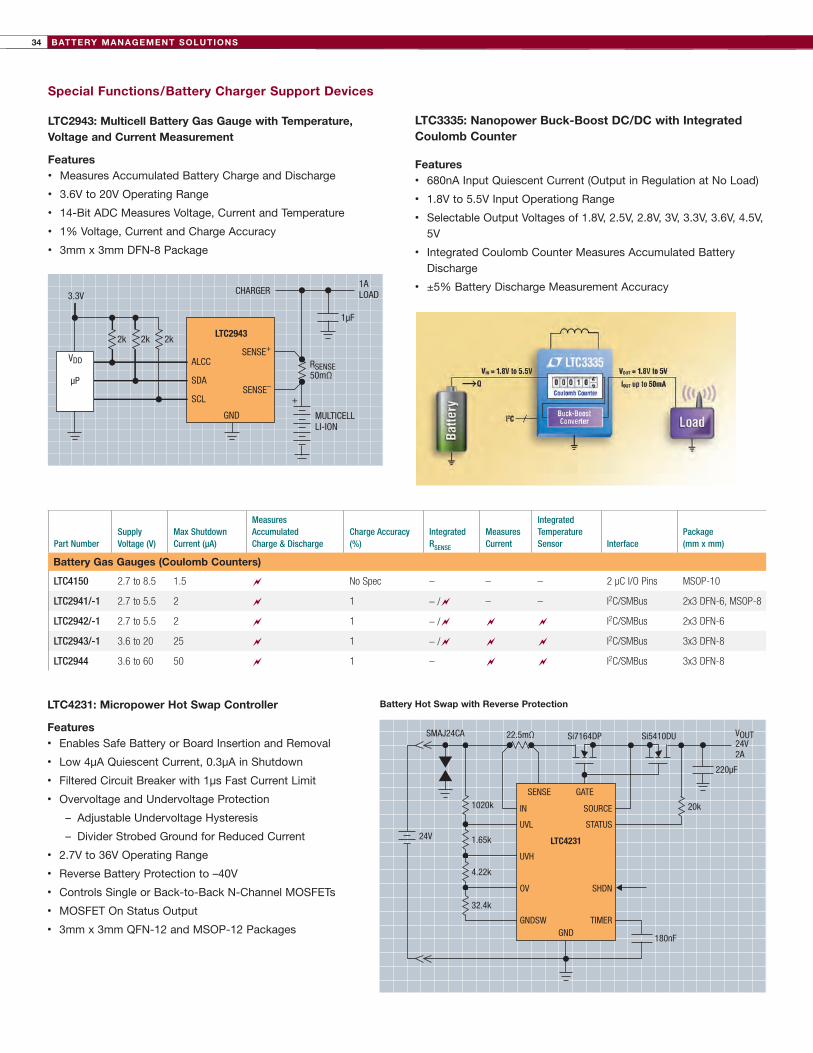
BATTERY MANAGEMENT SOLUTIONS34
LTC4231: Micropower Hot Swap Controller
Features• Enables Safe Battery or Board Insertion and Removal
• Low 4µA Quiescent Current, 0.3µA in Shutdown
• Filtered Circuit Breaker with 1µs Fast Current Limit
• Overvoltage and Undervoltage Protection
– Adjustable Undervoltage Hysteresis
– Divider Strobed Ground for Reduced Current
• 2.7V to 36V Operating Range
• Reverse Battery Protection to –40V
• Controls Single or Back-to-Back N-Channel MOSFETs
• MOSFET On Status Output
• 3mm x 3mm QFN-12 and MSOP-12 Packages
Special Functions/Battery Charger Support Devices
LTC2943: Multicell Battery Gas Gauge with Temperature, Voltage and Current Measurement
Features• Measures Accumulated Battery Charge and Discharge
• 3.6V to 20V Operating Range
• 14-Bit ADC Measures Voltage, Current and Temperature
• 1% Voltage, Current and Charge Accuracy
• 3mm x 3mm DFN-8 Package
Part NumberSupply Voltage (V)
Max Shutdown Current (µA)
Measures Accumulated Charge & Discharge
Charge Accuracy (%)
Integrated RSENSE
Measures Current
Integrated Temperature Sensor Interface
Package (mm x mm)
Battery Gas Gauges (Coulomb Counters)
LTC4150 2.7to8.5 1.5 ~ NoSpec – – – 2μCI/OPins MSOP-10
LTC2941/-1 2.7to5.5 2 ~ 1 –/~ – – I2C/SMBus 2x3DFN-6,MSOP-8
LTC2942/-1 2.7to5.5 2 ~ 1 –/~ ~ ~ I2C/SMBus 2x3DFN-6
LTC2943/-1 3.6to20 25 ~ 1 –/~ ~ ~ I2C/SMBus 3x3DFN-8
LTC2944 3.6to60 50 ~ 1 – ~ ~ I2C/SMBus 3x3DFN-8
SENSE+
ALCC
SDA
SCL
LTC2943
CHARGER
2k2k 2k
1ALOAD
RSENSE50mΩ
MULTICELLLI-ION
SENSE–
+
GND
1µF
VDD
3.3V
µP
Battery Hot Swap with Reverse Protection
SENSE GATE
IN
UVL
UVH
OV
GNDSW
SOURCE
STATUS
SHDN
TIMER
LTC4231
Si7164DPSMAJ24CA 22.5mΩ Si5410DU
GND
20k
220µF
VOUT24V2A
1020k
1.65k24V
4.22k
32.4k
180nF
LTC3335: Nanopower Buck-Boost DC/DC with Integrated Coulomb Counter
Features• 680nA Input Quiescent Current (Output in Regulation at No Load)
• 1.8V to 5.5V Input Operationg Range
• Selectable Output Voltages of 1.8V, 2.5V, 2.8V, 3V, 3.3V, 3.6V, 4.5V, 5V
• Integrated Coulomb Counter Measures Accumulated Battery Discharge
• ±5% Battery Discharge Measurement Accuracy

35BATTERY MANAGEMENT SOLUTIONS
Nano-Current Supervisors
Portable applications will appreciate the low power consumption of
our nano-current supervisors, which can directly monitor voltages up
to 36V. Resistor-programmable or pin-selectable thresholds provide
flexibility in small footprints.
LTC2960 36V Nano-Current 2-Input Voltage Monitor
Features• 850nA Quiescent Current
• Operating Range: 2.5V < VCC < 36V
• 1.5% (Max) Accuracy Over Temperature
• Adjustable Reset Threshold
• Adjustable IN+/IN– Threshold
• 2mm × 2mm DFN-8 and TSOT-8 Packages
Special Functions/Battery Charger Support Devices
LTM®2884: Isolated USB Transceiver with Isolated Power
Features• Isolated USB Transceiver: 2500VRMS for 1 Minute
• USB 2.0 Full Speed and Low Speed compatible
• Integrated Isolated DC/DC Converter, External or Bus Powered
• Auto-Configuration of Bus Speed
• 15mm x 15mm BGA-44 Package
Part Number
# of Voltage Monitors (# of Adj Inputs)
Monitor Voltages (V)
Threshold Accuracy
Reset Pulse Width
Supply Current (µA)
Power Fail Warning
Manual Reset Comments
Package (mm x mm)
Nano-Current Supervisors
LTC2960 2(2) Adj 1.5% 15ms/200ms 0.85 ~ ~ ResistorProgrammableResetandUV/OVThresholds TSOT-8,2x2DFN-8
LTC2934 1(1) Adj 1.5% 15ms/200ms 0.5 ~ ~ ResistorProgrammableResetandPower-FailThresholds TSOT-8,2x2DFN-8
LTC2935 1(1) 1.6to6 1.5% 200ms 0.5 ~ ~ 8Pin-SelectableResetandPower-FailThresholds TSOT-8,2x2DFN-8
+
ISOL
ATIO
N BA
RRIE
R
VLO
500mA AT 5V
ON
4.4V TO 16.5V
VBUS
VBUS2
8.6V TO 16.5V
100µF
VCC
SPNDPWR
D1+
D1–
VCC2
VLO2
D2+DOWNSTREAM
USB PORT
D2–
GND2GND15k 15k
PWR
HUBµC
Powered 2.5W Isolated Hub Port Bus Powered 1W Isolated Peripheral Device
VLO
ON
SPNDPWR
VCC2
VBUS
VBUS
GND
GND2GND
UPSTREAMUSB PORT
VCC
ISOL
ATIO
N BA
RRIE
R
200mA AT 5V
D1+
PERIPHERAL
D1–
VLO2
D2+
D2–
PWR
1.5k
+
VCC
IN+
DVCC
GND
RST
OUTADJMR
LTC3632DC/DC
GND
Li-Ion4.2V
+Li-Ion4.2V
C10.1µF50V
C21µF
R26.04M
R1402k
6V < VIN < 8.4V
R41.3M
R3402k
VOUT1.8V
RESET
LOW BATTERY
POWER-FAIL FALLING THRESHOLD = 6.410VRESET FALLING THRESHOLD = 1.693V
LTM2884 LTM2884
LTC2960-3

BATTERY MANAGEMENT SOLUTIONS36
Pushbutton Controllers
Our pushbutton controllers solve the inherent bounce problem associated with all mechanical contacts, while also enabling power supply
converters and releasing a processor once the supply is fully powered up. Wide voltage operation, rugged ESD protection, small size, low
quiescent current and ease of design distinguish these pushbutton controllers from discrete implementations.
LTC2955: Pushbutton On/Off Controller with Automatic Turn-On
Features• Automatic Turn-On via Voltage Monitor Input
• Wide Input Supply Range: 1.5V to 36V
• Low Supply Current: 1.2μA
• ±25kV ESD HBM on PB Input
• ±36V Wide Input Voltage for PB Input
• 3mm x 2mm DFN-10 and TSOT-8 Packages
Part Number Description
Supply Voltage
Supply Current
Turn-On Debounce Time
System OK Response Time
Interrupt Debounce Time
Turn-Off Debounce Time
Turn-Off Delay ESD Package
Pushbutton Controllers
LTC2950 BasicPushbuttonController 2.7Vto26V 6µA Adj 512ms Adj n/a 1024ms 10kV TSOT-8,DFN-8
LTC2951 BasicPushbuttonController 2.7Vto26V 6µA 128ms 512ms Adj n/a Adj 10kV TSOT-8,DFN-8
LTC2952 PushbuttonControllerwith2IdealDiode-ORControllersforLoadSharingorAutomaticSwitchoverApplications
2.7Vto28V 25µA Adj 400ms 26ms Adj 400ms 8kVTSSOP-20,QFN-20
LTC2953 PushbuttonControllerwithSupplyMonitor,UVLOandPowerFailComparatorsforSupervisoryApplications
2.7Vto27V 12µA 32ms 512ms 32ms Adj n/a 10kV DFN-12
LTC2954 PushbuttonControllerwithInterruptLogicforMenu-DrivenApplications
2.7Vto26V 6µA Adj 512ms 32ms Adj n/a 10kV TSOT-8,DFN-8
LTC2955 PushbuttonControllerwithAutomaticTurn-OnandInterruptLogicforMenu-DrivenApplications
1.5Vto36V 1.2µA 32ms 512ms 32ms Adj n/a 25kV TSOT-8,DFN-10
LTC2956 Wake-UpTimerwithPushbuttonController 1.5Vto36V 0.3µA 32ms n/a n/a Adj n/a 25kVMSOP-12,DFN-12
LT3008-3.3
VOUTVIN
PB
ON
INT
KILL
PGD
VIN
SELLTC2955DDB-1
GNDTMR
EN
3.3V
1M R71M
2.32M
SHDN
0.1µF
8.4V
VTRIP = 5.4V
µP
POWER-FAIL
402k

37BATTERY MANAGEMENT SOLUTIONS
High Side and Low Side Current Sensing
Sensing and controlling current flow is a fundamental requirement
in many battery charger and monitor applications.
High side current sense amplifiers extract small differential
voltages from high common mode voltages. This is used
to measure the voltage on a small sense resistor placed in
series between a power supply and load, providing a direct
measurement of current flowing into the load.
In some applications, low side current sensing can be used,
where a sense resistor is placed between load and ground. The
best solutions for low side sensing are micropower, rail-to-rail
input amplifiers with low input bias current and low offset voltage.
For more information, see our complete current sense solutions
guide at www.linear.com/currentsense Dual Current Sensor for Charge/Discharge Monitoring
Part Number Directional SenseInput Voltage Range (V)
Response Time (µs) VOS Max (µV)
VOS Offset Drift IBIAS Max Gain Settings Package
High Side Current Sense Amplifiers
LT1787 Bidirectional 2.5to65 10 75 0.5µV/°C 20µA FixedGain=8 SO-8,MSOP-8
LT1787HV Bidirectional 2.5to65 10 75 0.5µV/°C 20µA FixedAv=8 SO-8,MSOP-8
LTC4151 Unidirectional 7to80 n/a 4000 n/a n/a n/a DFN-10,MSOP-10
LT6100 Unidirectional 4.1to48 40 300 0.5µV/°C 10µA 10,12.5,20,25,40,50V/V DFN-8,MSOP-8
LTC6101 Unidirectional 4to105 1 300 1µV/°C 170nA Adjw/2Resistors SOT-23,MSOP-8
LTC6101HV Unidirectional 5to105 1 300 1µV/°C 170nA Adjw/2Resistors SOT-23,MSOP-8
LTC6102 Unidirectional 4to105 1 10 25nV/°C 3nA Adjw/2Resistors DFN-8,MSOP-8
LTC6102HV Unidirectional 5to105 1 10 50nV/°C 3nA Adjw/2Resistors DFN-8,MSOP-8
LTC6103 Unidirectional 4to70 1 450 1.5µV/°C 170nA Adjw/2Resistors/amp MSOP-8
LTC6104 Bidirectional 4to70 1 450 1.5µV/°C 170nA Adjw/3Resistors MSOP-8
LT6105 Unidirectional -0.3to44 3.5 300 0.5µV/°C 25µA Adjw/2Resistors DFN-6,MSOP-8
LT6106 Unidirectional 2.7to44 3.5 250 1µV/°C 40nA Adjw/2Resistors SOT-23
LT6107 Unidirectional 2.7to44 3.5 250 1µV/°C 40nA Adjw/2Resistors SOT-23
LT1999 Bidirectional -5to80 2.5 750 5µV/ºC 2.5µA 10,20,50V/V MSOP-8,SO-8
LT6108 Undirectional 2.7to60 3 125 0.8µV/ºC 300µA Adjw/2Resistors MSOP-8,DFN-8
LT6109 Undirectional 2.7to60 3 125 0.8µV/ºC 300µA Adjw/2Resistors MSOP-8
LT6118 Undirectional 2.7to60 3 125 0.8µV/ºC 300µA Adjw/2Resistors MSOP-8,DFN-8
LT6119 Undirectional 2.7to60 3 125 0.8µV/ºC 300µA Adjw/2Resistors MSOP-8
Part Number DescriptionRail- to-Rail
Direction Sense
Input Voltage Range (V)
VOS Max (µV) VOS Drift
IBIAS Max Gain Package
Low Side Current Sense Amplifiers
LT6015/6/7 Single/Dual/QuadPrecisionOver-the-TopOpAmps In/Out Bidirectional 0to76 50 0.75µV/°C 5nAAdjw/2Resistors
ThinSOT,MSOP-8,DFN-22
LT1490A/91A Dual/QuadOver-The-Top®µPowerRail-to-RailOpAmps In/Out Bidirectional 0to44 500 4µV/°C 8nAAdjw/2Resistors
DFN-8,DIP-8,MSOP-8,SO-8,DIP-14,SO-14
LT1636 Over-The-TopMicropower,Rail-to-RailSingleSupplyOpAmp
In/Out Bidirectional 0to44 225 5µV/°C 8nAAdjw/2Resistors
DFN-8,DIP-8,MSOP-8,SO-8
LT1638/39 1.2MHz,Over-The-TopMicropowerRail-to-RailOpAmp In/Out Bidirectional 0to44 600 6µV/°C 50nAAdjw/2Resistors
DFN-8,DIP-8,MSOP-8,SO-8,DIP-14,SO-14
LTC2054/55 Single/DualLowPower,Zero-Drift,3V,5V,±5VOpAmps Out Bidirectional 0toV±0.7 3 0.05µV/ºC 3nAAdjw/2Resistors
ThinSOT,DFN-8,MSOP-8
LT6105 Precision,HighSideorLowSide,CurrentSenseAmplifier In Unidirectional -0.3to44 300 1µV/°C 25µAAdjw/2Resistors
DFN-6,MSOP-8
LTC2057 HighVoltageLowNoiseZero-DriftOpAmp Out Bidirectional -0.1toV±1.5 5 0.225µV/ºC 200µAAdjw/2Resistors
DFN-8,MSOP-8,MSOP-10,SO-8
5V 0.1µFLT1999-10
4k
160k
160k
2µA
0.8k4k
V+
+–
SHDN
+– VOUT
40k
VREF
VSHDN
V+
V+
V+
V+4
0.1µF
5V
CHARGER
LOAD
0.025
BAT42V
VCCVREF
0.1µF
+IN
10µF
CS
SCK
SDO
LTC2433-1VOUT
+
–
5V
–IN
0.1µF
2
3
1
5
7
6
8
V+IN
V–IN
0.8k
LT1999: High Voltage, Bidirectional Current Sense Amplifier

BATTERY CHARGING SOLUTIONS38
Batte
ry
Char
ge T
erm
inat
ion
& In
tegr
atio
nSt
atus
Sig
nals
Tem
pera
ture
Con
trol
Pack
age
(mm
x m
m)
Part
Num
ber
Number of Battery Cells (Series)
Battery Charge Current (Max), A
Standalone
Charge Termination
Integrated Pass Transistor
ICHARGE Monitor #
End-of-Charge Signal
AC Present Signal
Thermal Regulation
Thermistor Interface
Inte
grat
ion/
Feat
ures
Mos
t Le
ast
Li-I
on/
Po
lym
er 4
.2V
/Cel
l & 4
.1V
/Cel
l Lin
ear
Bat
tery
Cha
rger
s w
ith
Po
wer
Pat
h C
ont
rol (
Po
wer
Man
ager
s)
11.5
~~
¶~
~~
–~
~QFN-20
LTC4
099
11.5
~~
¶~
~~
–~
~QFN-20
LTC4
160
11.5
~~
¶~
~~
–~
~QFN-20
LTC4
098
11.5
~~
¶~
~~
–~
~QFN-20
LTC4
098-
3.6
††
11.5
~~
¶~
~~
–~
~DFN-14
LTC4
088
11.2
~~
¶~
~~
~~
~DFN-22
LTC4
090
11.2
~~
¶~
–~
~~
~DFN-22
LTC4
089
11.5
~~
‡~
~**
~~
~~
QFN-24
LTC4
066
11.25
~~
‡~
–~
~~
~QFN-16
LTC4
055
11.25
~~
‡~
~~
–~
~DFN-12
LTC4
067
11.5
~~
‡~
–~
~~
~DFN-14
LTC4
085
Li-I
on/
Po
lym
er 4
.2V
/Cel
l & 4
.1V
/Cel
l Lin
ear
Bat
tery
Cha
rger
s
11
~~
¶~
~~
~~
~DFN-10
LTC4
061
11
~~
¶~
~~
–~
–DFN-10
LTC4
062
11
~~
¶~
~~
–~
–DFN-10
LTC4
063
12
~~
‡–
–~
~–
~MSO
P-10
LTC4
050
11.25
~~
‡~
~~
~~
~DFN-10
MSO
P-10
LTC4
053
1-14
0.25
~~
‡~
~~
–~
~DFN-10
LTC4
079
10.95
~~
†~
~~
~~
–DFN-10
LTC4
078/
X
10.95
~~
†~
~~
~~
–DFN-10
LTC4
075/
X
11.2
~~
†~
~~
~~
–DFN-10
LTC4
096/
X
*CurrentC/10,†CurrentC/x,‡ Timer,§µC,¶Timer+CurrentIndication,#PRO
GPinTracksChargeCurrent,**GasGaugeCapability,†† For1
-CellLiFePO 4
MA
ST
ER
SE
LE
CT
OR
GU
IDE
S—
Po
wer
Man
ager
s an
d L
inea
r B
atte
ry C
har
ger
sL i t h i um- I on /Po l yme r
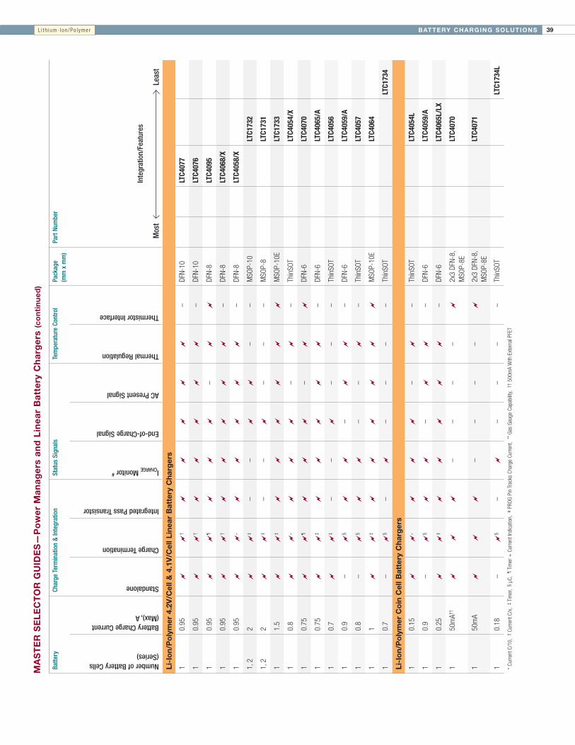
39BATTERY CHARGING SOLUTIONS
Batte
ry
Char
ge T
erm
inat
ion
& In
tegr
atio
nSt
atus
Sig
nals
Tem
pera
ture
Con
trol
Pack
age
(mm
x m
m)
Part
Num
ber
Number of Battery Cells (Series)
Battery Charge Current (Max), A
Standalone
Charge Termination
Integrated Pass Transistor
ICHARGE Monitor #
End-of-Charge Signal
AC Present Signal
Thermal Regulation
Thermistor Interface
Inte
grat
ion/
Feat
ures
Mos
tLe
ast
Li-I
on/
Po
lym
er 4
.2V
/Cel
l & 4
.1V
/Cel
l Lin
ear
Bat
tery
Cha
rger
s
10.95
~~
†~
~~
~~
–DFN-10
LTC4
077
10.95
~~
†~
~~
~~
–DFN-10
LTC4
076
10.95
~~
¶~
~~
–~
~DFN-8
LTC4
095
10.95
~~
†~
~~
~~
–DFN-8
LTC4
068/
X
10.95
~~
*~
~~
~~
–DFN-8
LTC4
058/
X
1,2
2~
~‡
––
~~
––
MSO
P-10
LTC1
732
1,2
2~
~‡
––
~–
––
MSO
P-8
LTC1
731
11.5
~~
‡~
~~
~~
~MSO
P-10E
LTC1
733
10.8
~~
*~
~~
–~
–ThinSO
TLT
C405
4/X
10.75
~~
¶~
~~
–~
~DFN-6
LTC4
070
10.75
~~
‡~
~~
~~
–DFN-6
LTC4
065/
A
10.7
~~
‡–
–~
––
–ThinSO
TLT
C405
6
10.9
–~
§~
~–
~~
–DFN-6
LTC4
059/
A
10.8
–~
§~
~–
–~
–ThinSO
TLT
C405
7
11
~~
‡~
~~
~~
~MSO
P-10E
LTC4
064
10.7
–~
§–
~–
––
–ThinSO
TLT
C173
4
Li-I
on/
Po
lym
er C
oin
Cel
l Bat
tery
Cha
rger
s
10.15
~~
*~
~~
–~
–ThinSO
TLT
C405
4L
10.9
–~
§~
~–
~~
–DFN-6
LTC4
059/
A
10.25
~~
‡~
~~
~~
–DFN-6
LTC4
065L
/LX
150mA†
†~
~~
––
––
~2x3DFN-8,
MSO
P-8E
LTC4
070
150mA
~~
~–
––
–~
2x3DFN-8,
MSO
P-8E
LTC4
071
10.18
–~
§–
~–
––
–ThinSO
TLT
C173
4L
*CurrentC/10,†CurrentC/x,‡ Timer,§ µC,¶Timer+CurrentIndication,#PRO
GPinTracksChargeCurrent,**GasGaugeCapability,†† 500m
AWithExternalPFET
MA
ST
ER
SE
LE
CT
OR
GU
IDE
S—
Po
wer
Man
ager
s an
d L
inea
r B
atte
ry C
har
ger
s (c
on
tin
ued
)L i t h i um- I on /Po l yme r

BATTERY CHARGING SOLUTIONS40
Batte
ry
Char
ge T
erm
inat
ion
& In
tegr
atio
nSt
atus
Sig
nals
Tem
pera
ture
Con
trol
Pack
age
(mm
x m
m)
Part
Num
ber
Number of Battery Cells (Series)
Battery Charge Current (Max), A
Standalone
Charge Termination
Integrated Power Transistor
ICHARGE Monitor‡‡
End-of-Charge Signal
AC Present Signal
Thermal Regulation
Thermistor Interface
Inte
grat
ion/
Feat
ures
Mos
t
L
east
NiM
H/N
iCd
Bat
tery
Cha
rger
s
1-16
4~
~#
––
~~
–~
TSSO
P-20E
LTC4
011
Switc
h M
ode
1-16
4~
~#
––
~~
–~
TSSO
P-16E
LTC4
010
Switc
h M
ode
1-4
2~
~§
––
~~
–~
DFN-16
TSSO
P-16
LTC4
060
Line
ar
Li-I
on/
Po
lym
er S
wit
ch M
od
e B
atte
ry C
harg
ers
14
~~**
~–
~~
~~
QFN-36
LT36
51-4
.x
24
~~**
~–
~~
~~
QFN-36
LT36
51-8
.x
12
~~
‡~
––
~–
~SSOP
-24
LTC4
001/
-1
1-2
2~
~**
~–
–~
~~
DFN-12
LT36
50
3-4
4~
~‡
–~
~~
–~
SSOP
-24
LTC4
007
1-4
0.4
~~
‡~
~~
–~
~QFN-16
LTC4
121
2-4
4~
~‡
–~
~~
–~
SSOP
-16
LTC4
006
1-2
2~
~‡
––
––
––
SSOP
-24
LTC1
980
1-2,adj
1.5
–~
¶,††
~–
~–
––
SSOP
-16
SSOP
-28
LT15
71
1-2
4~
~‡
––
~–
–~
DFN-10
SO-8
LTC4
002
*CurrentC/10,†CurrentC/x,‡ Timer,¶µC,§T,t,-dV,#T,t,-dV,dT/dt,**Timer+Current,††forLi-IonTermination,useLTC1729,‡‡PRO
GPinTracksChargeCurrent
MA
ST
ER
SE
LE
CT
OR
GU
IDE
S—
Sw
itch
Mo
de
Bat
tery
Ch
arg
ers
L i t h i um- I on /Po l yme r

41BATTERY CHARGING SOLUTIONSM
AS
TE
R S
EL
EC
TO
R G
UID
ES
—S
wit
ch M
od
e B
atte
ry C
har
ger
s (c
on
tin
ued
)
Batte
ry
Char
ge T
erm
inat
ion
& In
tegr
atio
nSt
atus
Si
gnal
sTe
mpe
ratu
re
Cont
rol
Pack
age
(m
m x
mm
)Pa
rt N
umbe
r
VBAT Range, V
Battery Charge Current (Max), A
Standalone
Charge Termination Method(s)
Integrated Pass Transistor
ICHARGE Monitor‡‡
End-of-Charge Signal
AC Present Signal
Thermal Regulation
Thermistor Interface
Inte
grat
ion/
Feat
ures
Mos
t
Le
ast
Sm
art
Bat
tery
Cha
rger
s
3.5-18
3~
SMBus‡
,¶–
––
~–
~QFN-38
LTC4
110
3.5-28
4~
SMBus¶
––
––
–~
TSSO
P-48
LTC1
760
3-21
8~
SMBus¶
––
–~
–~
SSOP
-36
LTC1
759
3.5-26
4~
SMBus¶
––
–~
–~
SSOP
-24
LTC4
100
3.0-5.5
4~
SMBus¶
––
–~
–~
SSOP
-24
LTC4
101
Lead
-Aci
d, L
i-Io
n/P
oly
mer
, NiM
H/N
iCd
Sw
itch
Mo
de
Bat
tery
Cha
rger
s
2.5-55
20A+
~
**
~
~~
–~
~
5x7QFN-38
LTC4
020
1-4
0.4
~~
‡~
~~
–~
~QFN-16
LTC4
121
1-14
0.25
~~
‡ ~
~
~–
~~
DFN-10
LTC4
079
3.5-28
8–
SPI¶
––
––
––
SSOP
-36,QFN-38
LTC1
960
2.5-23
8–
~¶,††
––
~–
––
SSOP
-28
LT15
05
3.3-18
2~
~**
~–
~–
~~
3x3DFN-12,M
SOP-12E
LT36
52HV
3.3-14.4
2~
~**
~–
~–
~~
3x3DFN-12,M
SOP-12E
LT36
52
2-28
4–
~¶
–~
–~
~–
QFN-20
LTC4
012/
-1/-
2/-3
2-28
4–
~¶
–~
–~
~–
QFN-20
LTC4
009/
-1/-
2
3-28
4~
¶–
–~
~–
~SSOP
-20
LTC4
008
2.5-26
3–
~¶,††
~–
––
––
SO-24
LT15
11
1.5-20
0.75
–~
¶,††
~–
––
––
SO-8
LT15
12
1.5-20
2–
~¶,††
~–
––
––
DDPak,TO-220
LT15
13
2.5-26
2–
~¶,††
~–
––
––
TSSO
P-20,SSO
P-28
LT17
69
2.5-26
1.5
–~
¶,††
~–
––
––
TSSO
P-16,SSO
P-28
LT15
71
2.5-26
1–
~¶,††
~–
––
––
SO-8,SSO
P-16,SO-16
LT15
10
*CurrentC/10,†CurrentC/x,‡ Timer,¶ µC,§T,t,-dV,#T,t,-dV,dT/dt,**Timer+Current,††forLi-IonTermination,useLTC1729,‡‡PRO
GPinTracksChargeCurrent
L i t h i um- I on /Po l yme r

BATTERY CHARGING SOLUTIONS42
Onbo
ard
Regu
lato
rsBa
ttery
Cha
rger
/Pow
er M
anag
erOt
her F
eatu
res
Pack
age
(mm
x m
m)
Part
Num
ber
Page
#Number of Regulators
Buck(s) (IOUT)
Buck-Boost (BB)/ Boost (IOUT)
LDO(s) (IOUT)
Li-Ion/Polymer Charger
Maximum Charge Current (A)
PowerPath Topology
Ideal Diode
Input Voltage (V)
Interface
Inte
grat
ion/
Feat
ures
Mos
tLe
ast
Li-I
on/
Po
lym
er M
ulti
func
tio
n P
ow
er M
anag
emen
t In
teg
rate
d C
ircu
its
(PM
ICs)
5400m
Ax2
1ABB,
0.8A
Boost
3.3V,20m
ASyncBuck
+Linear
1.5
SwitchMode
Int+
Ext(opt.)
5,USB,LiIon
–4x6QFN-38
LTC3
586/
-17,11
5600m
A,
400m
Ax2
10-LED
Boost
2x150m
ALinear
1.5
Linear
Int+
Ext(opt.)
5,USB,LiIon,
Hi-VBat-Track,
OVP
–4x7QFN-44
LTC3
577/
-1/-
3/-4
7,12
4600m
A,
400m
Ax2
–2x150m
ALinear
1.5
Linear
Int+
Ext(opt.)
5,USB,LiIon,
Hi-VBat-Track,
OVP
–4x7QFN-44
LTC3
677/
-312
4400m
Ax2,
1A
–3.3V,20m
ASyncBuck
+Linear
1.5
SwitchMode
Int+
Ext(opt.)
5,USB,Li-Ion,
Hi-V38Vwith
60Vtransients;
OVP:68V
I2 C4x6QFN-38
LTC3
576/
-17,11
4400m
Ax2
1ABB
3.3V,25m
ASyncBuck
+Linear
1.5
SwitchMode
Int+
Ext(opt.)
5,USB,LiIon
I2 C4x5QFN-28
LTC3
556
11
4600m
A,
400m
Ax2
–3.3V,25m
ALinear
1.5
Linear
Int+
Ext(opt.)
5,USB,LiIon,
Hi-V38Vmax
–4x4QFN-28
LTC3
557/
-17,12
41A,
400m
Ax2
–3.3V,25m
ASyncBuck
+Linear
1.5
SwitchMode
Int+
Ext(opt.)
5,USB,LiIon
I2 C4x5QFN-24
LTC3
555/
-1/
-37,11
3400m
A,
600m
A–
FlexibleGain
Blockfor
LDO
Controller
Linear
0.5
Linear
–5,USB,LiIon
–4x4QFN-24
LTC3
455/
-17,12
2–
1ABB
3.3V,25m
ASyncBuck
+Linear
1.5
SwitchMode
Int+
Ext(opt.)
4.25to5.5
–4x4QFN-24
LTC3
566
11
2–
1ABB
3.3V,25m
ASyncBuck
+Linear
1.5
SwitchMode
Int+
Ext(opt.)
4.25to5.5
I2 C4x4QFN-24
LTC3
567
11
2200m
Ax2
––
Linear
0.5
Linear
–4.35Vto5.5V
–3x3QFN-20
LTC3
554
12
2200m
A–
150m
ALinear
0.5
Linear
–4.35Vto5.5V
–3x3QFN-20
LTC3
553
12
2400m
A0.4ABB
–Linear
0.95
––
5,USB
–3x3QFN-20
LTC3
558
13
2400m
Ax2
––
Linear
0.95
––
5,USB
–3x3QFN-16
LTC3
559/
-17,13
2400m
A,
800m
A–
–Linear
0.95
––
4.25to8
–3x5DFN-16
LTC3
552/
-113
1600m
A–
–Linear
0.95
––
4.3to8
–3x5DFN-16
LTC3
550/
-113
1300m
A–
–Linear
0.5
––
2.7to4.5
–3x3DFN-10,
MSO
P-10E
LTC4
080
13
1300m
A–
–Linear
0.5
––
2.7to4.5
–3x3DFN-10
LTC4
081
13
MA
ST
ER
SE
LE
CT
OR
GU
IDE
S—
Mu
ltif
un
ctio
n P
MIC
sL i t h i um- I on /Po l yme r

43BATTERY CHARGING SOLUTIONS
μModule Battery Chargers
A µModule Power Product simplifies implementation, verification, and manufacturing of complex power circuits by integrating the power function
in a compact molded plastic package.
LTM8062/A: 32VIN, 2A μModule Power Tracking Battery Charger
Features• Complete Battery Charger System
• Input Supply Voltage Regulation Loop for Peak Power Tracking in MPPT (Maximum Peak Power Tracking) Solar Applications
• Resistor Programmable Float Voltage Up to 14.4V on the LTM8062 and 18.8V on the LTM8062A
• Wide Input Voltage Range: 4.95V to 32V (40V Abs Max)
• 9mm × 15mm × 4.32mm LGA Package
Applications• Industrial Handheld Instruments
• 12V to 24V Automotive and Heavy Equipment
• Desktop Cradle Chargers
• Solar Power Battery Charging
Onbo
ard
Regu
lato
rsBa
ttery
Cha
rger
/Pow
er M
anag
erOt
her F
eatu
res
Pack
age
(mm
x m
m)
Part
Num
ber
Page
#
Number of Regulators
Buck(s) (IOUT)
Buck-Boost (BB)/ Boost (IOUT)
LDO(s) (IOUT)
Li-Ion/Polymer Charger
Maximum Charge Current (A)
PowerPath Topology
Ideal Diode
Input Voltage (V)
Interface
Inte
grat
ion/
Feat
ures
Mos
tLe
ast
Li-I
on/
Po
lym
er M
ulti
func
tio
n P
ow
er M
anag
emen
t In
teg
rate
d C
ircu
its
(PM
ICs)
5400m
Ax2
1ABB,
0.8A
Boost
3.3V,20m
ASyncBuck
+Linear
1.5
SwitchMode
Int+
Ext(opt.)
5,USB,LiIon
–4x6QFN-38
LTC3
586/
-17,11
5600m
A,
400m
Ax2
10-LED
Boost
2x150m
ALinear
1.5
Linear
Int+
Ext(opt.)
5,USB,LiIon,
Hi-VBat-Track,
OVP
–4x7QFN-44
LTC3
577/
-1/-
3/-4
7,12
4600m
A,
400m
Ax2
–2x150m
ALinear
1.5
Linear
Int+
Ext(opt.)
5,USB,LiIon,
Hi-VBat-Track,
OVP
–4x7QFN-44
LTC3
677/
-312
4400m
Ax2,
1A
–3.3V,20m
ASyncBuck
+Linear
1.5
SwitchMode
Int+
Ext(opt.)
5,USB,Li-Ion,
Hi-V38Vwith
60Vtransients;
OVP:68V
I2 C4x6QFN-38
LTC3
576/
-17,11
4400m
Ax2
1ABB
3.3V,25m
ASyncBuck
+Linear
1.5
SwitchMode
Int+
Ext(opt.)
5,USB,LiIon
I2 C4x5QFN-28
LTC3
556
11
4600m
A,
400m
Ax2
–3.3V,25m
ALinear
1.5
Linear
Int+
Ext(opt.)
5,USB,LiIon,
Hi-V38Vmax
–4x4QFN-28
LTC3
557/
-17,12
41A,
400m
Ax2
–3.3V,25m
ASyncBuck
+Linear
1.5
SwitchMode
Int+
Ext(opt.)
5,USB,LiIon
I2 C4x5QFN-24
LTC3
555/
-1/
-37,11
3400m
A,
600m
A–
FlexibleGain
Blockfor
LDO
Controller
Linear
0.5
Linear
–5,USB,LiIon
–4x4QFN-24
LTC3
455/
-17,12
2–
1ABB
3.3V,25m
ASyncBuck
+Linear
1.5
SwitchMode
Int+
Ext(opt.)
4.25to5.5
–4x4QFN-24
LTC3
566
11
2–
1ABB
3.3V,25m
ASyncBuck
+Linear
1.5
SwitchMode
Int+
Ext(opt.)
4.25to5.5
I2 C4x4QFN-24
LTC3
567
11
2200m
Ax2
––
Linear
0.5
Linear
–4.35Vto5.5V
–3x3QFN-20
LTC3
554
12
2200m
A–
150m
ALinear
0.5
Linear
–4.35Vto5.5V
–3x3QFN-20
LTC3
553
12
2400m
A0.4ABB
–Linear
0.95
––
5,USB
–3x3QFN-20
LTC3
558
13
2400m
Ax2
––
Linear
0.95
––
5,USB
–3x3QFN-16
LTC3
559/
-17,13
2400m
A,
800m
A–
–Linear
0.95
––
4.25to8
–3x5DFN-16
LTC3
552/
-113
1600m
A–
–Linear
0.95
––
4.3to8
–3x5DFN-16
LTC3
550/
-113
1300m
A–
–Linear
0.5
––
2.7to4.5
–3x3DFN-10,
MSO
P-10E
LTC4
080
13
1300m
A–
–Linear
0.5
––
2.7to4.5
–3x3DFN-10
LTC4
081
13
2A µModule Battery Chargers
A B C D E F
BANK 1
FAULTADJBIAS
BANK 2BAT
GND
G H J K L
7
6
5
4
3
2
1
BANK 3
BANK 4
VIN
VINA
LGA PACKAGE77-LEAD (15mm × 9mm × 4.32mm)
TOP VIEW
CHRG GND
TMRNTC RUN VINREG
BATTERY VOLTAGE (V)0
0
CHAR
GING
CUR
RENT
(mA)
2
2500
1 3 4
1000
500
1500
2000NORMAL CHARGING
PRECONDITION
TERMINATION
Pin ConfigurationCharge Current vs Battery Voltage
Part NumberBattery Float Voltage (V)
Input Voltage (V) Charge Current (A) Battery Chemistry
Package Type
Package Dimensions (mm)
µModule Battery Chargers
LTM8061 4.1-8.4 4.95-32 2 Li-Ion,Li-Poly LGA 9x15x4.3
LTM8062 3.3-14.4 4.95-32 2 Li-Ion,Li-Poly,LeadAcid,LiFePO4 LGA 9x15x4.3
LTM8062A 3.3-18.8 4.95-32 2 Li-Ion,Li-Poly,LeadAcid,LiFePO4 LGA 9x15x4.3

Notes:

Sales Of f ices
NORTH AMERICA
WESTERN U.S.
2085 E. Technology Cir., Ste. 101Tempe, AZ 85284Tel: (480) 777-1600Fax: (480) 838-1104
7595 Irvine Center Dr., Ste. 120Irvine, CA 92618Tel: (949) 453-4650Fax: (949) 453-4765
11300 W. Olympic Blvd., Ste. 700Los Angeles, CA 90064Tel: (818) 703-0835Fax: (818) 703-0517
720 Sycamore Dr.Milpitas, CA 95035Tel: (408) 428-2050Fax: (408) 432-6331
3009 Douglas Blvd., Ste. 140Roseville, CA 95661Tel: (916) 787-5210Fax: (916) 787-0110
5090 Shoreham Place, Ste. 110San Diego, CA 92122Tel: (858) 638-7131Fax: (858) 638-7231
7102 La Vista Place, Ste. 201 Niwot, CO 80503Tel: (303) 926-0002Fax: (303) 530-1477
Salt Lake City, NVTel: (801) 731-8008
5285 SW Meadows Rd., Ste. 240Lake Oswego, OR 97035Tel: (503) 431-6960Fax: (503) 431-6961
2018 156th Ave. NE, Ste. 100Bellevue, WA 98007Tel: (425) 748-5010Fax: (425) 748-5009
MIDWEST U.S.
2040 E. Algonquin Rd., Ste. 512Schaumburg, IL 60173Tel: (847) 925-0860Fax: (847) 925-0878
IndianaTel: (847) 925-0860
IowaTel: (847) 925-0860
KansasTel: (913) 634-7966
MichiganTel: (440) 239-0817
7805 Telegraph Rd., Ste. 225Bloomington, MN 55438Tel: (952) 903-0605
MissouriTel: (913) 634-7966
Columbus, OHTel: (614) 488-4466
7550 Lucerne Dr., Ste. 106Middleburg Heights, OH 44130Tel: (440) 239-0817Fax: (440) 239-1466
WisconsinTel: (262) 331-4040
NORTHEAST U.S.
ConnecticutTel: (860) 228-4104
15 Research PlaceNorth Chelmsford, MA 01863Tel: (978) 656-4750Fax: (978) 656-4760
New YorkTel: (978) 656-4750
3220 Tillman Dr., Ste. 120Bensalem, PA 19020Tel: (215) 638-9667Fax: (215) 638-9764
SOUTHEAST U.S.
Huntsville, ALTel: (256) 881-9850
Fort Lauderdale, FLTel: (407) 688-7616
Orlando, FLTel: (407) 688-7616
Tampa, FLTel: (813) 634-9434
Atlanta, GATel: (770) 888-8137
170 Weston Oaks Ct.Cary, NC 27513Tel: (919) 677-0066Fax: (919) 678-0041
8500 N. Mopac, Ste. 603Austin, TX 78759Tel: (512) 795-8000Fax: (512) 795-0491
22515 Sail Harbour Ct.Katy, TX 77450Tel: (713) 463-5002
2301 W. Plano Pkwy., Ste. 109Plano, TX 75075Tel: (972) 733-3071Fax: (972) 380-5138
CANADA
Calgary, ABTel: (403) 455-3577
Vancouver, BCTel: (604) 783-3084
Ottawa, ONTel: (613) 680-3473
Toronto, ONTel: (440) 239-0817
Montreal, QCTel: (514) 236-6261
ASIA/PACIFIC
AUSTRALIA/NEW ZEALAND
133 Alexander Street Crows Nest, NSW 2065, Australia Tel: +61 (0)2 9432 7803 Fax: +61 (0)2 9439 2738
Suite 121A, 89 High Street Kew, Victoria 3101, Australia Tel: +61 3 9854 6120
CHINA
Room 1763, Office Building New Century Hotel No. 6 Southern Road of Capital Gym Haidian District Beijing, China 100044 Tel: +86 (10) 6801-1080 Fax: +86 (10) 6805-4030
Unit 09, 14/F, Complex Building No. 88 Shenghe Yi Rd., Hi-Tech Zone Sichuan Province, Chengdu City China 610041 Tel: +86 028-8555 9725 Fax: +86 028-8542 6859
Unit 1503-04, Metroplaza Tower 2 223 Hing Fong Road Kwai Fong, N.T., Hong Kong Tel: +852 2428-0303 Fax: +852 2348-0885
Room 2701, City Gateway No. 398 Cao Xi North Road Shanghai, China 200030 Tel: +86 (21) 6375-9478 Fax: +86 (21) 5465-5918
Room 2109-2111, 21/F, Block D Southern International Plaza 3013 Yitian Road, Futian District Shenzhen, China 518048 Tel: +86 755-2360-4866 Fax: +86 755-2360-4966
Room 1805, Tower A Optics Valley International Plaza No. 889 Luoyu Rd., Wuchang District Wuhan, China 430074 Tel: +86 027-8665 9231 Fax: +86 027-8665 9241
Rm. 2410, Tower A, Greenland SOHO No. 5 ZhangBa 1 Road High-Tech Development Zone Shaanxi Province Xian, China 710065 Tel: +86 029-6851 8978 /68518979 Fax: +86 029-6851 8976
INDIA
602, 6th Floor, Prestige Meridian-1 No. 29, MG Road, Bangalore 560001, India Tel: +91 80 4012-4610 Fax: +91 80 4012-4612
JAPAN
7F, Sakuradori Ohtsu KT Bldg. 3-20-22 Marunouchi, Naka-ku Nagoya-shi, 460-0002, Japan Tel: +81 (52) 955-0056 Fax: +81 (52) 955-0058
6F Kearny Place Honmachi Bldg. 1-6-13 Awaza, Nishi-ku Osaka-shi, 550-0011, Japan Tel: +81 (6) 6533-5880 Fax: +81 (6) 6543-2588
8F Shuwa Kioicho Park Bldg. 3-6 Kioicho Chiyoda-ku Tokyo, 102-0094, Japan Tel: +81 (3) 5226-7291 Fax: +81 (3) 5226-0268
KOREA
Yundang Building, #1002 Samsung-Dong 144-23 Kangnam-Ku Seoul 135-090, Korea Tel: +82 (2) 792-1617 Fax: +82 (2) 792-1619
SINGAPORE
507 Yishun Industrial Park A Singapore 768734 Tel: +65 6753-2692 Fax: +65 6752-0108
TAIWAN
8F-1, 77, Nanking E. Rd., Sec. 3 Taipei, Taiwan Tel: +886 (2) 2505-2622 Fax: +886 (2) 2516-0702
EUROPE
FINLAND
Kirkkokatu 31 90100 Oulu, Finland Tel: +358 (0)46 712 2171 Fax: +358 (0)46 712 2175
Teknobulevardi 3-5, P.O. Box 35 FIN-01531 Vantaa, Finland Tel: +358 (0)46 712 2171 Fax: +358 (0)46 712 2175
FRANCE
Parc Tertiaire Silic 2 Rue de la Couture, BP10217 94518 Rungis CEDEX, France Tel: +33 (1) 56 70 19 90 Fax: +33 (1) 56 70 19 94
GERMANY
Haselburger Damm 4 D-59387 Ascheberg, Germany Tel: +49 (2593) 9516-0 Fax: +49 (2593) 951679
Osterfeldstrasse 84, Haus C D-85737 Ismaning, Germany Tel: +49 (89) 962455-0 Fax: +49 (89) 963147
Jesinger Strasse 65 D-73230 Kirchheim/Teck, Germany Tel: +49 (0)7021 80770 Fax: +49 (0)7021 807720
ITALY
Via Torri Bianche 3, Palazzo Larice 20871 Vimercate (MB), Italy Tel: +39 039 596 5080 Fax: +39 039 596 5090
SWEDEN
Electrum 204, Isafjordsgatan 22 SE-164 40 Kista, Sweden Tel: +46 (8) 623 16 00 Fax: +46 (8) 623 16 50
UNITED KINGDOM
3 The Listons, Liston Road Marlow, Buckinghamshire SL7 1FD United Kingdom Tel: +44 (1628) 477066 Fax: +44 (1628) 478153
,LT,LTC,LTM,LinearTechnology,theLinearlogo,BurstMode,Over-The-TopandµModuleareregisteredtrademarksandBat-Track,isoSPI,PowerPath,HotSwapandThinSOTaretrademarksofLinearTechnologyCorporation.Allothertrademarksarethepropertyoftheirrespective owners.
©2016LinearTechnologyCorporation

F0416OLU
25%
Linear Technology Corporation1630 McCarthy Blvd. Milpitas, CA 95035-7417 • Tel: 408-432-1900 • www.linear.com