batteries for dummies - nasa glenn research center explorers posts
TRANSCRIPT

BATTERY FUNDAMENTALS AND OPERATIONS
- Batteries for Dummies -
Presented by the Electrochemistry BranchDoris L. Britton Thomas B. Miller
April 4, 2000

4

OUTLINE
• BATTERIES
– FUNDAMENTAL– ELECTROCHEMICAL REACTIONS– PROPERTIES
• BATTERY SIZING APPLICATIONS

BATTERY
• BATTERY– A device that translates chemical energy into electricity.– Consist of one or more cells that are electrically connected
• CELL - A device capable of storing chemical energy and delivering it as electrical energy upon demand.
– POSITIVE electrode that receives electrons from the external circuit when the cell is discharged.
– NEGATIVE electrode that donates electrodes to the external circuit as the cell discharges.– ELECTROLYTE which provides a mechanism for charge flow between positive and negative
electrodes– SEPARATOR which electrically isolates the positive and negative electrodes.

BATTERY(OXIDATION - REDUCTION)
A is OXIDIZED
B is REDUCEDe e e e e
A B
OXIDATION involves a LOSS of electrons
REDUCTION involves a GAIN of electrons
+ e- OXIDATION
+X
+ e-
REDUCTIONHydrogen ion
Hydrogen atom
where e- represents an electron

ELECTROCHEMISTRY
• ANODE - is that electrode (or plate) at which oxidation occurs• CATHODE - is that electrode (or plate) at which reduction occurs• ELECTROCHEMICAL CELL - may either be a voltaic cell or an electrolytic cell
(depends on the direction)
– CHEMICAL ENERGY ELECTRICAL ENERGY
– CHEMICAL ENERGY ELECTRICAL ENERGY
VOLTAIC (e.g., battery)
ELECTROLYTIC (e.g., plating bath)
DISCHARGE
CHARGE
On Discharge: On Charge:
Negative plate - Anode Negative plate - Cathode
Positive plate - Cathode Positive plate - Anode

BATTERY CLASSIFICATIONS(Definitions)
• ELECTROCHEMICAL CELL :– A device which stored Chemical Energy is converted to Electrical Energy to provide electrical
power
• PRIMARY CELL:– An Electrochemical Cell which is useless when the energy is expended
• SECONDARY CELL– An Electrochemical Cell in which the chemical energy can be stored by reversing the flow of
electricity from an external power source.

BATTERY CLASSIFICATIONS(Definitions)
• RESERVE CELL :– A Primary Cell in which the electrolyte is stored in a separate sealed compartment to avoid
corrosion and self-discharge. The cell is used to provide very high power for short periods. Operation is done via electrolyte release or addition - in the case of a thermal battery, operation is done via melting a solidified electrolyte.
• ACTIVE CELL:– A cell containing all components in a charged state ready for discharge 9as distinct from a
RESERVED CELL).
• HALF CELL:– An electrode (either the anode or cathode) immersed in a suitable electrolyte.
• FLOODED CELL– An Electrochemical Cell in which the electrolyte covers the plates (excess electrolyte). It
usually has open ports to release gas and to replace the water converted to oxygen and hydrogen.

BATTERY CLASSIFICATIONS(Definitions)
• STARVED CELL :– An Electrochemical Cell in which the majority of the electrolyte is immobilized in the separator
and plates. This enables gases to reach electrode surfaces during charging and facilitate gas recombination.
• DRY CELL:– A cell with immobilized electrolyte. The term “dry cell” is often used to describe the
Leclanche cell.
• HERMETICALLY SEALED CELL:– A Starved Cell which is designed to prevent the loss of electrolyte or gas. The gas is
recombined within the cell during operation.

BATTERY CLASSIFICATIONS(Definitions)
• CAPACITY - The number of ampere-hours (Ahr) of stored energy in a single cell
– Rated - The nominal or nameplate capacity (manufacturer specified) as stated for specific conditions of temperature, current and end voltage.
– Standard - The capacity as measured under a standardized charge-discharge cycle.– Theoretical - The number of ampere-hour equivalents of stored chemical mass.– Measured - the capacity as measured under other than standard conditions
• DEPTH OF DISCHARGE - The ampere-hours removed on discharged expressed as a percentage of the rated capacity. The rated capacity is always used to calculate DOD and charge rates: C/2 rate, C/10 rate, etc.
– The advantage of using rated capacity is that it is fixed for the lifetime of the cell, so if one specifies a 40% DOD, the ampere-hours removed on discharge at the beginning of life are the same as the ampere-hours removed on discharge at the end of life.

BATTERY CLASSIFICATIONS(Definitions)
• SPECIFIC ENERGY - The measured capacity multiplied by the average discharge voltage divided by the cell mass:
Specific Energy = Cmeas x Vavg = WhrWeight of Cell kg
(Note: Use the measured capacity to calculate specific energy. The specific energy is used to compare one cell design to another and it should not be biased by an arbitrary rating.)
• ENERGY DENSITY - The measured capacity multiplied by the average discharge voltage divided by the cell volume:
Energy Density = Cmeas x Vavg = Whr Volume of cell l
(Note: Again use the measured capacity to calculate energy density. The energy density is used to compare one cell design to another.)

BATTERY(Basic Definitions)
• CHARGE: - The process of storing electrical energy in a secondary (rechargeable) battery by forcing current to flow through the battery in the charge direction, which restores discharged material to its charged state.
• OVERCHARGE = The forcing of current through a cell after all active materials has been converted to the charged state.
• CHARGE RATE = Rate at which current is input to the battery. Various definitions for the speed at which the battery is charged:
Charge Type Charge Rate Recharge Time (Hrs)
Ultra quick (very fast) Over C < 1 hr
Fast C < 2 hrs
Quick C/3 4 - 5
Standard C/10 16 - 20Minimum C/20 36 - 48
Trickle C/50 Used to maintaincharge on a fullycharged battery
BATTERY(Basic Definitions)
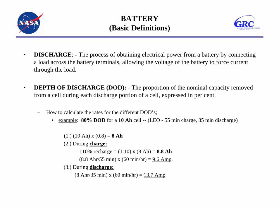
• DISCHARGE: - The process of obtaining electrical power from a battery by connecting a load across the battery terminals, allowing the voltage of the battery to force current through the load.
• DEPTH OF DISCHARGE (DOD): - The proportion of the nominal capacity removed from a cell during each discharge portion of a cell, expressed in per cent.
– How to calculate the rates for the different DOD’s;• example: 80% DOD for a 10 Ah cell -- (LEO - 55 min charge, 35 min discharge)
(1.) (10 Ah) x (0.8) = 8 Ah(2.) During charge:
110% recharge = (1.10) x (8 Ah) = 8.8 Ah(8.8 Ahr/55 min) x (60 min/hr) = 9.6 Amp.
(3.) During discharge:(8 Ahr/35 min) x (60 min/hr) = 13.7 Amp

BATTERY(Basic Definitions)
• SERVICE LIFE - The period of useful life of a battery before a predetermined end-point voltage is reached.
• SHELF LIFE - The duration of storage under specified conditions at the end of which a cell or battery still retains the ability to give a specified performance
• SELF-DISCHARGE - The loss of useful capacity of a cell or battery on storage due to internal chemical reactions.

Glenn Research Center
Power and On-Board Propulsion Technology Division
Planetary Orbiters
Planetary Rover
Planetary Lander GEO Spacecraft
LEO SpacecraftAstronaut Equipment
NASA BATTERY APPLICATIONSNASA BATTERY APPLICATIONS

Glenn Research Center
Power and On-Board Propulsion Technology DivisionAEROSPACE BATTERY KEY
PERFORMANCE PARAMETERS
• Weight– Specific Energy - The energy storage ability of a battery on a weight basis)
(Wh/kg =volts x Ah/wt.,kg)• Ah = based on the on the total capacity of positive plates in a cell.
• Volume– Energy Density - Wh/l
• Efficiency = ratio of output energy to input energy
• Shelf Life/Calendar Life
• Cycle Life = the number of cyclic operations (charge-discharge) which acell or battery will tolerate prior to failure
• Operational Temperature Range– Thermal system design
• Safety/Reliability
• Cost

Glenn Research Center
Power and On-Board Propulsion Technology Division
Parameter Rovers Landers GEO RLVLEO/
PlanetaryOrbiters
Nominal Voltage 14 28 28 100 28Capacity (AH) 7 20 20 200 20
Temp Range (oC) -30 to +45 -20 to +45 -5 to +30 -40 to + 65 -5 to +30
Life (Cycles) >500 >500 1,000 1,000 30,000Discharge Rate C/5 to 1C C/5 to 1C 2C/3 C C
Charge Rate C/5 to C/2 C/5 to C/2 C/20 C C/2
NASA AEROSPACE CELL AND BATTERY REQUIREMENTS
Glenn Research Center
Power and On-Board Propulsion Technology Division
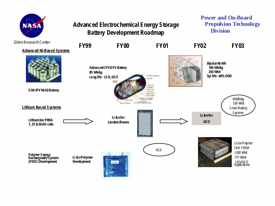
Advanced Electrochemical Energy StorageBattery Development Roadmap
Lithium Ion PRDA7, 25 & 50 AH cells
FY99 FY00 FY01 FY02 FY03
Bipolar Ni-MH 100 Wh/kg 250 Wh/l5yr life - 40% DOD
SOA IPV Ni-H2 Battery
Li-Ion forLanders/Rovers
Li-Ion forGEO
Li-Ion PolymerDevelopment
Advanced Ni-Based Systems
Lithium Based Systems
Advanced CPV/SPV Battery85 Wh/kgLong life - LEO, GEO
85Wh/kg130 Wh/l
Smart BatterySystems
Li-Ion PolymerFAR TERM>200 Wh/l175 Wh/k LEO/GEOApplicati ons
RLVPolymer EnergyRechargeable System(PERS) Development

Electrochemical Systems
• Nickel-Cadmium• Nickel-Hydrogen
– Individual Pressure Vessel (IPV)– Common Pressure Vessel (CPV)– Single Pressure Vessel (SPV)– Dependent Pressure Vessel (DPV)– Bipolar
• Nickel Metal Hydride• Lithium • Sodium Sulfur• Silver Zinc• Primary:
– Lithium Sulfur Dioxide– Lithium Thionyl Chloride– Thermal

ELECTROCHEMICAL REACTIONS FOR NICKEL-CADMIUM CELL
(Normal Operation)
Positive electrode: NiOOH + H2O + e- Ni(OH)2 + OH-
discharge
charge
Negative electrode: 1/2 Cd + OH- 1/2 Cd(OH)2 + e-discharge
charge
Net reaction: 1/2 Cd + NiOOH + H2O Ni(OH)2 + 1/2 Cd(OH)2
discharge
charge

ELECTROCHEMICAL REACTIONS FOR NICKEL-CADMIUM CELL(Overcharge and Reversal)
Overcharge (Normal positive-limited cell):
Nickel electrode: OH - 1/2 H2O + 1/4 O2 + e -
Cadmium electrode: 1/2 Cd(OH)2 + e- 1/2 Cd + OH-
1/4 O2 + 1/2 H20 + 1/2 Cd 1/2 Cd(OH)2
Overcharge (Negative-limited cell):
Nickel electrode: H2O + e- OH- + 1/2 H2
Cadmium electrode: H2O + e- (OH)- + 1/2 H2
*Hydrogen gas will be generated at the negative electrode and will build up pressure, because it is not recombined at any significant rate.
Reversal (positive-limited cell):
Nickel electrode: H2O + e- (OH)- + 1/2 H2
Cadmium electrode: 1/2 Cd + (OH)- 1/2 Cd(OH)2 + e-

Nickel-Cadmium Batteries
• Temperatures– - 20 to +50 deg C (operating)– - 40 to + 50 deg. C (storage)
• Nominal Voltage - 1.25 V• Lifetime - 3 years (LEO)
6 years (GEO)• Specific Energy - 30 to 45 Wh/kg• Energy Density - 70 Wh/l
• Self Discharge Rate - 1% per day at 25 deg. C
• Applications– Aircraft batteries– Industrial & emergency power– communications
• Advantages– Very rugged– Good charge retention– Good cycle life– Good high rate capability
• Disadvantages– Memory effect– Thermal runaway– Low energy density

ELECTROCHEMICAL REACTIONS FOR NICKEL-HYDROGEN CELL
(Normal Operation)
(1) Nickel electrode: NiOOH + H2O + e- Ni(OH)2 + OH-
discharge
charge
(2) Hydrogen electrode: 1/2 H2 + OH- H2O + e-discharge
charge
(3) Net reaction: 1/2 H2 + NiOOH Ni(OH)2
discharge
charge

ELECTROCHEMICAL REACTIONS FOR NICKEL-HYDROGEN CELL
(Overcharge)
(4) Positive electrode: 2OH - 2e - + 1/2 O2 + H2O
(5) Negative electrode: 1/2 O2 + H2O + 2e- 2OH-
Net reaction of (4) and (5): No net change.
(6) Positive electrode: H2O + e- OH- + 1/2 H2
(7) Chemical Recombination of O2: 1/2 O2 + H2 H2O
*Chemical recombination (7) can cause popping if the localized mixture of oxygen and hydrogen is in the combustible range.

ELECTROCHEMICAL REACTIONS FOR NICKEL-HYDROGEN CELL
(Reversal)
Hydrogen Precharge
(8) Positive electrode: H2O + e- OH - + 1/2 H2
(9) Negative electrode: 1/2 H2 + 2OH- H2O + e-
Net reaction: No change
Positive Precharge
(10) Positive electrode: 2 NiOOH + 2H2O + 2e- 2Ni(OH)2 + 2(OH)-
(11) Negative electrode: 2 (OH)- 2e- + 1/2 O2 + H2O
Net reaction: 2NiOOH + H2O 2 Ni(OH)2 + 1/2 O2
Build up of oxygen pressure and discharge of the Ni oxide electrode.
*When all of the positive precharge is used (10), then H2 gas is formed at the positive electrode [same as (8)] and consumed at the hydrogen electrode [same as (9)].

Nickel-Hydrogen Cell
• Applications– Space applications (LEO, GEO, Planetary Orbiters, Landers)– Communication satellites
• Advantages– Long cycle life at deep DOD– Resistant to overcharge– Good energy density– Advantageous for high power missions
• Disadvantages– High cost– High pressure cell– Low volumetric energy density

ELECTROCHEMICAL REACTIONS FOR NICKEL-METAL HYDRIDE CELL
NORMAL REACTIONS
MOHNiHMNiOOH
eOHMOHHM
OHOHNieOHNiOOH
+⇔+
++⇔+
+⇔++
−
−−
2
2
22
)(][
][
)(D
CPositive electrode:
Negative electrode:
OVERALL:

ELECTROCHEMICAL REACTIONS FOR NICKEL-METAL HYDRIDE CELL
OVERCHARGE
MHOOHM
OHMHeOHM
eOHOOH
22/12
)(22222
22/1)(2
22
2
22
+→+
+→++
++↑→
−−
−−Positive electrode:
Negative electrode:
OVERALL:

ELECTROCHEMICAL REACTIONS FOR NICKEL-METAL HYDRIDE CELL
OVERDISCHARGE (POLARITY REVERSAL)
−−
−−
+→+
+→+
eOHOHH
OHHeOH
22)(2
)(222
22
22Positive electrode:
Negative electrode:

NICKEL-METAL HYDRIDE CELL
• General classes of metallic alloys (negative electrode):– Rare earth/nickel alloys = based around LaNi5 (AB5)– Alloys consisting primarily of Ti and Zr (AB2)
Advantages Disadvantages
AB2 • High Specific Energy• Most reliable raw material supply• Passes EPA Toxic Characteristic Leachate
Procedure
• Alloy corrosion• Generally Steep Pressure Isotherm
Slope
AB5 • Flat Pressure Isotherm Slope• Good charge retention
• Lower specific energy• Varaible Misch Metal Raw Material
Supply• May be pyrophoric• May not pass EPA Toxic Characteristic
Leachate Procedure

Nickel Metal Hydride
• Temperatures– -20 to +50 deg C (operating)– - 40 to +50 deg. C (storage)
• Nominal Voltage -– 1.2V
• Lifetime– 5 years (LEO)
• Specific Energy – 53 Wh/kg (Cell)– 44 Wh/kg (Battery)
• Energy Density– 50 - 75 Wh/l (Battery)
• Self Discharge Rate - 2% per day at 25 deg. C
• Applications– Future space missions (LEO,
Planetary Orbiters, Landers)– Commercial consumer spin-offs
(lawnmowers, computers, EVs)• Advantages
– 2X specific energy of Ni-H2
– 1/2 cost of Ni-H2
– Compact for small spacecraft• Disadvantages
– High self-discharge– Failure leading to high pressure– Embrittlement of alloys on
cycling.

NICKEL-METAL HYDRIDE
• Commercial Cell Manufacturers;– Japan
• Sanyo, Matsushita, Japan Storage Battery– Hongkong
• Gold Peak– Germany
• Varta– U.S.A
• Energizer/Gates• Ovonic Battery (OBC)• Duracell• Hardy Energy Storage• Eagle-Picher• Rockwell

Advantages of the Ni-MH over Ni-Cd
• The practical specific energies of Ni-MH are considerably higher than Ni-Cd by almost 1.5-2X, even though the theoretical specific energy is not much higher than Ni-Cd (216 Wh/kg as compared to 209 for Ni-Cd).
• The improvement in the volume density is more significant, esp.. for consumer applications. The theoretical energy density of 1134 Wh/l for Ni-MH is higher than 751 Wh/l for Ni-Cd. Accordingly, the practical energy density is also higher, about 160-200 Wh/l as compared to 70-120 Wh/l. This translate into a higher capacity and energy density for equivalent-size cells. The increase is attributed to the accommodation of larger positive electrodes in the same size case because of the smaller size of the MH electrode when compared to Cd.
• The voltage characteristics of the Ni-MH as well as charge cutoff methods are similar enough to permit a replacement of Ni-Cd with the higher energy Ni-MH cell for consumer applications.

Advantages of the Ni-MH over Ni-Cd (cont’d..)
• The Ni-MH cell utilizes an oxygen recombination mechanism during overcharge as in Ni-Cd which allows a sealed configuration for these batteries. Also, these systems have a built-in tolerance to overdischarge in the form of hydrogen reabsorption.
• Both the electrode reactions in the Ni-MH are solid state reactions involving proton intercalation and deintercalation. The absence of a dissolution precipitation reaction such as the taking place of the Cd electrode implies an absence of dendritic shorts that often limit the cycle life of the Ni-Cd.
• MHs are not known to be toxic and appear to be environmetally acceptable. These batteries, therefore, pose no known problems for handling and disposal.
• These batteries are comparable to Ni-Cd in terms of rate capability and are amenable to fast charge as well.
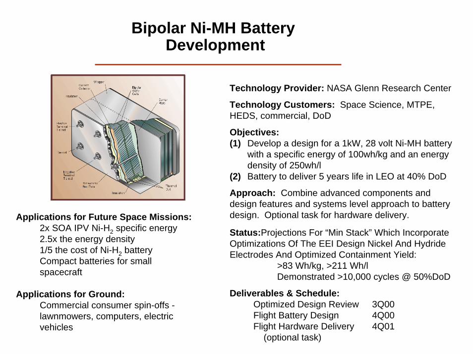
Bipolar Ni-MH Battery Development
Technology Provider: NASA Glenn Research Center
Technology Customers: Space Science, MTPE, HEDS, commercial, DoD
Objectives:(1) Develop a design for a 1kW, 28 volt Ni-MH battery
with a specific energy of 100wh/kg and an energy density of 250wh/l
(2) Battery to deliver 5 years life in LEO at 40% DoD
Approach: Combine advanced components and design features and systems level approach to battery design. Optional task for hardware delivery.
Status:Projections For “Min Stack” Which Incorporate Optimizations Of The EEI Design Nickel And Hydride Electrodes And Optimized Containment Yield:
>83 Wh/kg, >211 Wh/lDemonstrated >10,000 cycles @ 50%DoD
Deliverables & Schedule:Optimized Design Review 3Q00Flight Battery Design 4Q00Flight Hardware Delivery 4Q01
(optional task)
Applications for Future Space Missions:2x SOA IPV Ni-H2 specific energy2.5x the energy density1/5 the cost of Ni-H2 batteryCompact batteries for small spacecraft
Applications for Ground:Commercial consumer spin-offs -lawnmowers, computers, electric vehicles

TYPES OF LITHIUM CELLS
• Lithium metal
– anode - metallic Li– cathode - insertion cathode (e.g., TiS2, MoS2, V2O5, LiCoO2, LiNiO2)– electrolyte - liquid organic
• Lithium-ion
– anode - carbon/graphite (intercalation compound) – cathode - high voltage cathode (e.g., LiCoO2, LiNiO2, LiMn2O4)– electrolyte - liquid or polymer

TYPES OF LITHIUM CELLS
• Lithium-Based Polymer Electrolyte
– Lithium metal polymer electrolyte• Lithium metal as the anode• A PEO (polyethylene oxide) based true polymer
– Lithium-ion polymer electrolyte• Carbon/graphite anode• Gel type electrolyte • Solid polymer electrolyte (solvent-free)
– Lithium-Based Solid State Electrolyte (thin-film)• Ceramics or glasses (e.g., Li phosphate)

COMPONENTS OF A LITHIUM BATTERY
• POSITIVE ELECTRODE (Cathode):
– Compounds that can intercalate lithium ions (intercalation = a layer located between layers of different character)
– Transition metal oxides - Co, Ni, V, etc.
• NEGATIVE ELECTRODE (Anode):
– “Lithium” cell = Lithium Metal
– “Lithium ion” cell = Lithium-carbon (LiC6)
221 LiCoOeCoOLixLi x ↔++ −−
+ D
C
−+ +↔ eLiLiD
C
−+ ++↔ eCxLiCLixD
C

LITHIUM BATTERIES
• ELECTROLYTE:
– Liquid Electrolyte:
• (Lithium salt) + (solvent mixture)
– e.g.: (LiPF6, etc.) + (ethylene carbonate, propylene carbonate, etc.)
– Polymer Electrolyte:
• (Lithium salt) + (Polymer) + (Small amount of solvent)
– e.g.: (LiPF6, etc.) + (hexafluoropropylene + Polyvinylidene fluoride) + (EC, PC)
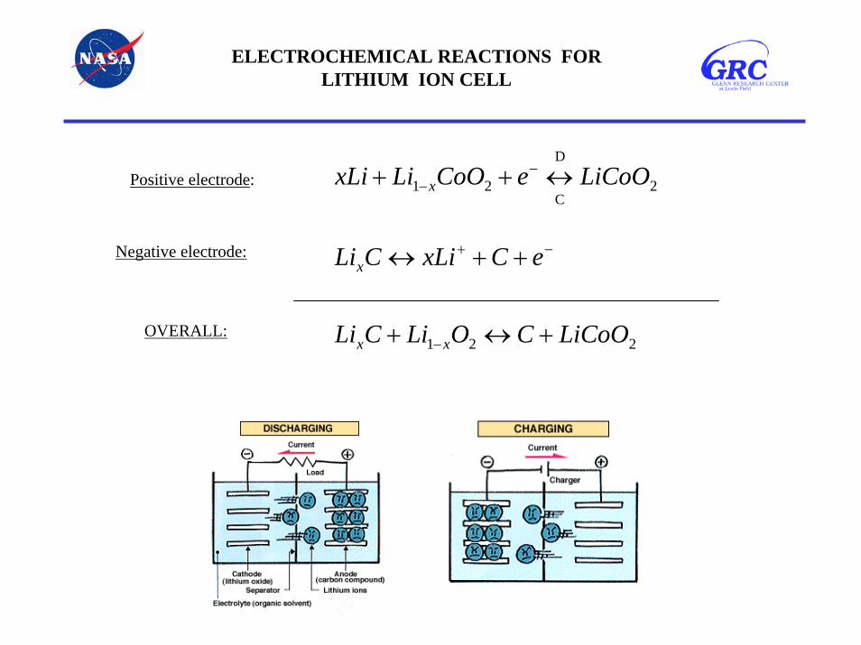
ELECTROCHEMICAL REACTIONS FOR LITHIUM ION CELL
221
221
LiCoOCOLiCLi
eCxLiCLi
LiCoOeCoOLixLi
xx
x
x
+↔+
++↔
↔++
−
−+
−−
D
CPositive electrode:
Negative electrode:
OVERALL:

•CELL REACTION : Li C + Li CoO LiCoO + C
•SCHEMATIC DIAGRAM OF A Li-ION CELL•CARBON ANODE
•_
•ELECTROLYTE
•+
•Li•+•O
•O
•O
•O
•Co
•Li
•Li•Li•+
•d spacing •Li•+
•Li•+
•3.8 V (3.65 V under load)
•Layered Structure of LiCoO
•2 •2•x •1 - x
•C
•D
•OXIDE CATHODE
•2

Lithium Ion
• Applications– Future space missions (LEO,
Planetary Orbiters, Landers)– Astronaut equipment– Earth orbiting spacecraft
(GEO/LEO)– Air Force (unmanned aerial
vehicle, military aircraft)– Commercial consumer
• Advantages– Low battery & launch cost– High energy density & operating
voltages– Long storage life
• Disadvantages– Overcharge problem– Capacity retention
• Temperatures– -5 to +30 deg C
• Nominal Voltage -– 3.5V
• Lifetime– 1200 cycles (100% DOD)
• Specific Energy – 125 Wh/kg
• Energy Density– 300 Wh/l
• Self Discharge Rate - 1% per month

LITHIUM ION CELL(For MARS Rover)
Cycle Life of Li ion cells (4-7 Ah) at 25 deg. C for Mars Rover applications.
Discharge capacity as a function of rate and temperature of Li ion cell for Mars Rover.

Glenn Research Center
Power and On-Board Propulsion Technology DivisionRechargeable Li-Ion Batteries
Product Metrics Li-Ion
Specific Energy > 100 Wh/kgEnergy Density > 160 Wh/lSel f Discharge < 10 %/monthEnergy Efficiency > 90%
State-of-the-Art
Ni-Cd and Ni-H2
30-40 Wh/Kg40-80 Wh/l10-30%/month
< 75%
Li-Ion Batteries offer improved specific energy andenergy density over traditional battery systems

Glenn Research Center
Power and On-Board Propulsion Technology Division
• REDUCED POWER SYSTEM MASS- 25 % OF Ni-Cd/Ni-H2 BATTERY MASS- 200-230 kg MASS SAVINGS FOR 8-10 kW GEO PAYLOADS
• REDUCED POWER SYSTEM VOLUME- 25 % OF Ni-Cd/Ni-H2 BATTERY VOLUME- SIMPLER POWER SYSTEM INTEGRATION
• LOWER LAUNCH COSTS- REDUCED POWER SYSTEM WEIGHT- REDUCED SOLAR ARRAY SIZE
• ENABLE SMALL SPACECRAFT AND PLANETARY MISSIONS- ENERGY CAPABILITY- TEMPERATURE PERFORMANCE- CONFORMABLE GEOMETRY
LITHIUM BATTERY TECHNOLOGYPAYBACKS

LANDER CELL PERFORMANCE
2.3
2.5
2.7
2.9
3.1
3.3
3.5
3.7
3.9
4.1
0 20 40 60 80 100 120 140 160Specific Energy (Watt-Hr/Kg)
Cel
l Vol
tage
(V)
2.5 Amp Charge Current (C/10)4.1 V Taper to C/50 Cut-Off
- 30oC - 20oC 0oC 23o 40oC
5.0 Amp Discharge Current (C/5)
0
5
10
15
20
25
30
35
40
45
0 1 2 3 4 5 6 7 8 9
Time (Hours)
Cha
rge
Cap
acity
(Ah)
Cell charged to 4.1 VConstant potential charge to C/50
5.0 A Charge Current (C/5) to 4.1 V
40oC 23oC
0oC
- 20oC
- 30oC

LANDER CELL PERFORMANCE
15
20
25
30
35
0 25 50 75 100 125 150 175 200 225 250Cycle Number
Dis
char
ge C
apac
ity (A
h)Room Temperature and +40oC Cycling
5.0 A Charge Current (C/5)4.1 V (Taper to C/50)
5.0 A Discharge Current (C/5) 3.0 V Cut-off voltage
40oC
23oC
-20oCLow Temperature (-20oC) Cycling
2.5 A Charge Current (C/10)4.1 V (Taper to C/50)
5.0 A Discharge Current (C/5) .3.0 V Cut-off voltage
Charge and discharge at low temperature
0
5
10
15
20
25
30
35
40
0 100 200 300 400 500 600 700 800 900Cycle Number
Dis
char
ge C
apac
ity (A
h)
Charge Current (C/5)4.1 V (Taper to C/50)
Discharge Current (C/5)3.0 V Cut-off voltage
- 20oCCharge Current (C/10)4.1 V (Taper to C/50)
Discharge Current (C/5)3.0 V Cut-off voltage
25oC

MARS 2001 Lander Battery
Voltage: 28-32.8 VCapacity at RT 31 AhCapacity at -20C: 25 AhCycle Life: 500 CyclesOp.Temp: -20 to 40CWeight: 8 KgVolume: Sp. Energy: 112 Wh/kgEnergy Density:
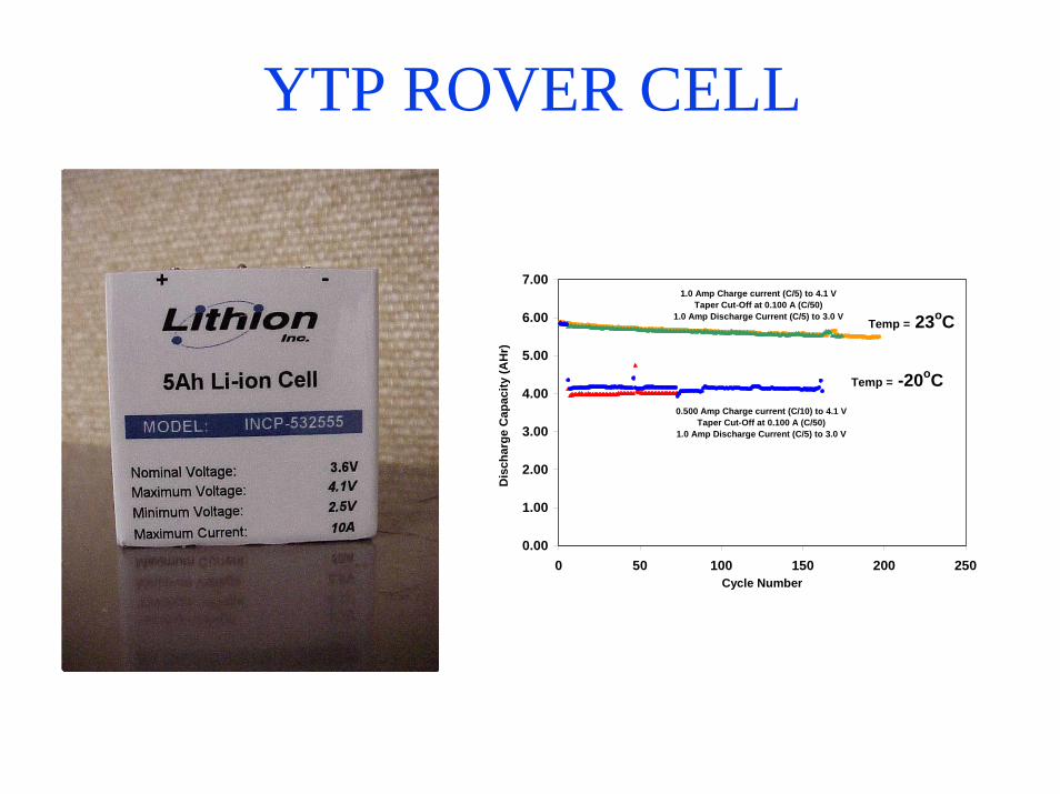
YTP ROVER CELL
0.00
1.00
2.00
3.00
4.00
5.00
6.00
7.00
0 50 100 150 200 250Cycle Number
Dis
char
ge C
apac
ity (A
Hr)
1.0 Amp Charge current (C/5) to 4.1 VTaper Cut-Off at 0.100 A (C/50)
1.0 Amp Discharge Current (C/5) to 3.0 V
0.500 Amp Charge current (C/10) to 4.1 VTaper Cut-Off at 0.100 A (C/50)
1.0 Amp Discharge Current (C/5) to 3.0 V
Temp = -20oC
Temp = 23oC

Glenn Research Center
Power and On-Board Propulsion Technology Division
Lithium-Ion Polymer Battery
30 Volt, 50 AH Battery 8 Cells
1500 Wh - 20 kg to tal mass – 75 Wh/kg7.8 liters vo lume – 190 Wh/l
Nickel Hydrogen Battery
33 Volt, 35 AH Battery27 Cells
1150 Wh - 30 kg to tal mass – 40 Wh/kg58 liters volume – 20 Wh/l
Lithium-Ion Polymer Battery vs.Nickel-Hydrogen Battery

Glenn Research Center
Power and On-Board Propulsion Technology DivisionLithium Polymer Battery
Development
Lithium-based Polymer batteries are beingdeveloped as an energy storage system for avariety of applications, including planetaryorbiters, rovers and landers, GEO and LEOsatellites, EAPU’s for the Space Shuttle and forresuable launch vehicles like the Bantam vehicle.
This compact, light-weight, conformabletechnology will enable and enhance missionswithin each of the NASA Enterprises.

Glenn Research Center
Power and On-Board Propulsion Technology DivisionLithium Polymer Batteries
Benefits over Conventional BatteriesPerformance Advantages• Reduced battery weight and volume - high specific energy and high energy density•Improved energy and coulombic efficiency•Lower self discharge rates
Reduced System Complexity•Higher cell operating voltage (3.5 volts vs 1.2 volts)•Conformable geometry – cells are flexible•Solid State Construction - No free electrolyte•Reduced cost – cell and battery level manufacturing•Prismatic construction
Smart batteries – independent cell charge/discharge controllers•Keeps cells in balance•Extends cycle life•Reduced heat generation rates

Glenn Research Center
Power and On-Board Propulsion Technology Division
C anodeLiMnO2
Bel lcore,Ultralife ,Valence,Alliant
Li-metalPEO electrolyte
Li-V6O12
3-M
Li-acetyleneGel electrolytePolysulfides
APL, MolTech,PolyPlus Universities
PERSAF/NASAProgram
NASA LITHIUM BATTERY PROGRAMRELATIONSHIPS
NASA LITHIUM BATTERY PROGRAMRELATIONSHIPS
Technology Flight Ready Technology Demonstration Basic Research - Feasibility
Readiness Level 6-8 4-6 1-3
Spe
cific
Ene
rgy,
Wh/
kg
Present TIME Future
C anodeLixCoO2
Commercia l,EPI, SAFT,Yardney,Blue Star
Lithium-Ion Liquid
Electrolyte
Lithium-ionGel Electrolyte
Lithium-metalPolymer
Electrolyte
All Polymer
Lithium-polymer
Gel Electrolyte

SODIUM SULFUR BATTERY CELL
3232 SNaSNa ↔+Basic Reaction:

Sodium-Sulfur Battery Cell Features
• NaS Cells Must be heated to 350ÞC• Molten Sodium Anode, Molten Sulfur Cathode, Beta”-Alumina Ceramic
Separator/Sodium Ion Conducting Electrolyte• Overall Cell Reaction: Discharge 2Na + xS Na2Sx
• Charge Na2Sx 2Na + xS• Manufacture Eagle Picher Industries Inc. Joplin, Mo• Capacity 40 Ampere-Hours• Voltage 2.0 Volts nominal• Weight 1.0 lbs• Diameter 1.396 inches• Length 9.44 inches
0ÞC
50ÞC 200ÞC 300ÞC 400ÞC100ÞC
NaSBatteries
NiCdNiH2
H2OBoiling Pt.
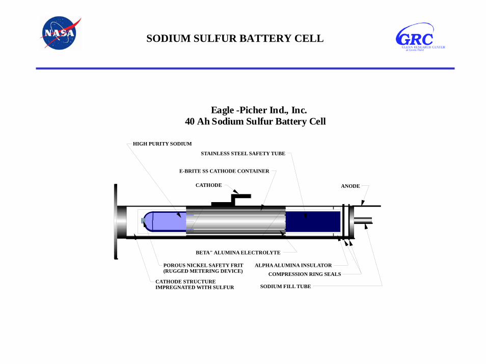
SODIUM SULFUR BATTERY CELL
Eagle -Picher Ind., Inc. 40 Ah Sodium Sulfur Battery Cell
SODIUM FILL TUBE
ALPHA ALUMINA INSULATOR
HIGH PURITY SODIUM
BETA" ALUMINA ELECTROLYTE
STAINLESS STEEL SAFETY TUBE
E-BRITE SS CATHODE CONTAINER
ANODECATHODE
CATHODE STRUCTURE IMPREGNATED WITH SULFUR
POROUS NICKEL SAFETY FRIT (RUGGED METERING DEVICE) COMPRESSION RING SEALS

Phase III: Naval Research Lab Flight Experiment
• Objectives– Demonstrate the capability for NaS cells to operate in micro-
g environment– Investigate the effect of zero-g on cell performance, material
(electrode) transport, and interfacial reactions• Approach
– Short term orbital test with recovery– Ground test of identical unit at AFRL– Cell destructive physical analysis (DPA) of all cells
• Payoff– Validate and understand cell operation in zero-g– Gain industry advocacy by test report publication– Provide benchmark for battery level development
NaSBE Flight Experiment Conducted on STS-87 in November 1997 Demonstrated that Sodium-Sulfur Cells
Could Operate in a Microgravity Environment

Sodium Sulfur
• Applications– Aerospace
• Microgravity– Terrestrial
• Electric utility load loading• Electric Vehicle
• Advantages– Excellent performance– Low cost (0.5x Ni-H2)– High temp– High power density– High discharge capability– Good cycle life
• Disadvantages– Cell reliability
• Temperatures– +350 deg C
• Nominal Voltage -– 2.08V
• Lifetime– 12,000 LEO (60% DOD)
• Specific Energy – 120 Wh/kg (Battery)
• Energy Density– 300 Wh/l
• Storage/Shelf Life - cell will remain at the top of charge for extended periods.

ELECTROCHEMICAL REACTIONS FOR SILVER-ZINC CELL
ZnAgOZnOAg
OHZnOHZnOe
eOHAgOOHAg
+↔+
+↔++
++↔+
−−
−−
22
22
2
2
C
D
C
D
Positive electrode:
Negative electrode:
C
DOVERALL:

Silver Zinc
• Temperatures– +18 to +38 deg C
• Nominal Voltage -– 1.6 to 1.86
• Lifetime - limited• Specific Energy
– 55 - 286 Wh/kg (Cell)– 37 - 253 Wh/kg (Battery)
• Energy density– 80 - 415 Wh/l (Cell)– 55 - 262 Wh/L (Battery)
• Storage/Shelf Life– one year or as little as 30 days
(except for reserve types)
• Applications– Electronic equipment– Torpedoes– Missiles & space– Small submersibles– Surgical tools
• Advantages– Highest energy & power
densities of rechargeable batts– Good voltage regulation - flat
discharge voltage– Good shock and vibration
resistance• Disadvantages
– Relatively high cost– Limited cycle life

ELECTROCHEMICAL REACTIONS FOR LITHIUM THIONYL CHLORIDE PRIMARY
CELL
22
22
424
444
442
SOSLiClSOClLi
eLiLi
SOSCleSOCl
++→+
+→
++→+
−+
−−Positive electrode:
Negative electrode:
OVERALL:

Primary Lithium Thionyl Chloride
• Applications– Wide range of applications
including computer memories,and stand-by power
• Advantages– Highest energy density– Long shelf life– Very low self-discharge rate– Good performance over wide
temp range• Disadvantages
– No high rate discharge capability– Fair but limited shelf life
• Temperatures– (-55 to +150 deg C)
• Nominal Voltage -– 2.6 to 3.6 V
• Specific Energy – 500 Wh/kg
• Storage/Shelf Life– Storage T= (-55 to +85 deg C)
• Self Discharge Rate– 3.5% up to 10 years
Primary Lithium Sulfur Dioxide
• Reaction:
• Applications– Military and special industrial
application requiring high rate and/or low temp. performance.
• Advantages– High energy density– Excellent low temp. and high
rate performance• Disadvantages
– High cost– Pressurized system requires
special precautions for manufacture and use
• Temperatures– (- 60 to + 80 deg C)
• Nominal Voltage -– 2.3 to 3.0 V
• Specific Energy – 280 Wh/kg
• Energy Density– 440 Wh/l
• Storage/Shelf Life– 10 years at RT– 5 years at elev.. T
• Self Discharge Rate -– <10% at 20 deg. C/5 yr.– <35% at 70 deg. C/yr..
422222 OSLiSOLi →+

Glenn Research Center
Power and On-Board Propulsion Technology Division
24
20
16
12
8
4
0PAST PRESENT FUTURE
Ni-Cd
IPV Ni-H2
22 Cell SPVNi-H2
REL
ATIV
E B
ATT
ERY
MA
SS
Li-ION
EVOLUTION OF FLIGHT BATTERIESEVOLUTION OF FLIGHT BATTERIES
2 Cell CPVNi-H2
Li-BasedPolymer

MANUFACTURERS’ WEB PAGES
• Battery Design Company – http://www.batdesign.com/links.htm
• Energizer --– http://www.energizer.com/
• Battery Business in the United States– http://energy.sourceguides.com/businesses/byGeo/US/b
yP/batP/batt/batt.shtml
MORE
4FEATURING …...


LEO & GEO Mission Parameters
Low-Earth-Orbit (LEO)200-500 nm altitudeOrbital period = 80-100 minutesDesign point = 90 minutes total16 cycles/day = 5840 cycles/year
55 minutes sunlight35 minutes eclipse
Geosynchronous (GEO)22,766 nm altitudeOrbital period = 23 hr. 56 min. 4 sec.Design point = 24 hours total~ 42 eclipse encounters per season centered around spring & fall equinox
varying from a few seconds to 72 min. 1 yr. GEO = 2 eclipse seasons ~ 90 discharge cycles
National Aeronautics andSpace AdministrationGlenn Research Center
Power & OnPower & On--BoardBoardPropulsion TechnologyPropulsion Technology
DivisionDivision

Advanced Nickel Based Battery Development
• Improved lightweight components and alternate Ni-H2 battery designs offer improved specific energy and energy density
– Bipolar Nickel-Hydrogen– CPV Nickel-Hydrogen– SPV Nickel-Hydrogen– Bipolar Nickel-Metal Hydride

Power & OnPower & On--BoardBoardPropulsion TechnologyPropulsion Technology
DivisionDivision
Ni/H2 Packaging NomenclatureNational Aeronautics andSpace AdministrationGlenn Research Center
Individual Pressure Vessel (IPV) - houses a stack configuration in a cylinder where eachelectrode pair is electrically paralleled to provide a nominal 1.25 Volts on discharge.
Common Pressure Vessel (CPV) - houses 2 distinct stacks wired in series in a cylinder toyield a nominal 2.5 Volts on discharge.
Single Pressure Vessel (SPV) - houses multiple series connected cells in a cylinder that provides a packaged battery with a nominal discharge of 28 Volts from 22 cells.
Dependent Pressure Vessel (DPV) - houses multiple parallel connected rectangular cells in a canteen shaped pressure vessel that provides a nominal 1.25 Volts on discharge.
Bipolar Design - Battery packaging concept that eliminates inter-cell electrical connectionsby inserting a “bipolar plate” between adjacent cells. The bipolar plate conducts currentthroughout the entire planar surface to the next electrochemical cell.

Power & OnPower & On--BoardBoardPropulsion TechnologyPropulsion Technology
DivisionDivision
Ni/H2 “Cell” Level ComparisonsNational Aeronautics andSpace AdministrationGlenn Research Center
NominalDischarge
Voltage
NominalChargeVoltage
SpecificEnergyWh/Kg
EnergyDensity
Wh/l
IPV 1.25 1.55 42-53 49-88
CPV 2.5 3.10 43-53 70-83
SPV 28 34 51-60 51-67
DPV 1.25 1.55 55 68

Lightweight Nickel Electrode Development
• OBJECTIVE:– Develop and demonstrate an optimized nickel electrode for
Nickel-based batteries to improve overall specific energy and energy density.
• APPROACH:– Optimize alternate lightweight substrates (fiber, felt, graphite,
plastic) to replace sintered nickel substrate– Joint in-house and contract development efforts– Verification test:
• Boilerplate hardware• Flightweight hardware

COMPONENT WEIGHTS OF LIGHTWEIGHT NICKEL-HYDROGEN CELLS (50 AH)
1. SOA (Eagle-Picher) 4. Bekaert Fibre Technologies
2. Memtec America 5. Auburn University
3. Ribbon Technology
0
200
400
600
800
1000
1200
1400
1600
1 2 3 4 5
WEI
GHT
, gm
Nickel electrode
Hydrogen electrode
Separator, electrolyte
Gas screen, vessel,end platesMiscellaneous

Electrochemical Energy StorageTechnology Paths - Batteries
Cell W-hr/kgBattery W-hr/kg
W-hr/lLife-years LEO/GEODOD - % - LEO/GEO
Cell W-hr/kgBattery W-hr/kg
W-hr/lLife-years LEO/GEODOD - % - LEO/GEORel. Cost
Cell W-hr/kgBattery W-hr/kg
W-hr/lLife-years LEO/GEODOD - % - LEO/GEORel. Cost
Cell W-hr/kgBattery W-hr/kg
W-hr/lLife-years LEO/GEODOD - % - LEO/GEORel. Cost
Cell W-hr/kgBattery W-hr/kg
W-hr/lLife-years LEO/GEODOD - % - LEO/GEORel. Cost
Cell W-hr/kgBattery W-hr/kg
W-hr/lLife-years LEO/GEODOD - % - LEO/GEORel. Cost
Ni-Cd
IPV Ni-H2
CPV Ni-H2
Ni-MH
Li-IonLiquid
Li-IonPolymer
30-4525-3730-45
3/615/60
Space Station - LEO472710
5/1235/701.0
45-6036-50
305/1235/701.0
Prismatic5344
50-755-LEO
351.0
Commercial10080110N/AN/A1.0
120-13090
180-200N/AN/A1.0
805525
8/1540/700.8
807040
8/1540/700.6
BipolarN/A801753/1040/600.5
>100851302/1040/600.5
>200>150>2003/1040/60
.6
Lightweight Ni1007540
10/2040/800.5
Lightweight Ni/OptimizedDesign
1008560
10/2040/800.5
Bipolar/Lightweight NiN/A1002505/2040/750.5
140>1202005/1540/600.5
>2001752208/2050/750.2
Technology Parameter State-of-the-Art Near Term Future

Deep Space 1
Mission:Its first destination was the near-Earth steroid Braille. Deep Space 1 flew by this asteroid on July 28, 1999. The New Millennium Program is conducting to demonstrate new technologiesin the environment of space.Launch:October 24, 1998 from Cape Canaveral, Florida. Completion:Deep Space 1 began thrusting toward Comet Wilson-Harrington less than 36 hours after encountering Braille.Batteries: CPV NiH2, 12AH, 11-Cell, Dual String

MARS GLOBAL SURVEYOR
BATTERY2 BATTERIES / 8 NiH2 CP V’S PER BATTERYVOLTAGE MONITORED AT BATTERY AND HALF BATTERY LEVEL2 STRAIN GAUGES AND 2 TEMPERATURE SENSORS PER BATTERYCHARGE CONTROL: V/T WITH PRESSURE AND AHR INTEGRATION
REGIME11 MONTH CRUISE ( THREE 40% DOD CYCLES)MODIFIED AEROBRAKING (TO MAINTAIN S/A INTEGRITY)~8500 MAPPING CYCLES (29% DOD) AND ~14,000 RELAY CYCLES (24% DOD)
Launched 6 Nov. 1996Regulated Direct Energy Transfer System
4 Solar Array Panels (2 GaAs, 2 Si) Capable of Generating 667 W @ Aphelion 2 - 20 Amp-hr Nickel Hydrogen (Ni-H2) Batteries 28 Vdc +/-2% Regulated Bus

MARS SURVEYOR ‘98Mars Climate OrbiterLaunch: Dec 10, 199
Mars Orbit: Sep 23, 1999
Mars Polar LanderLaunch: Jan 3, 1999Mars Landing: Dec 3, 1999
ORBITER BATTERY REQUIREMENTS 13,500 CYCLES @ 50% DODBOTH ORBITER AND LANDER WILL USE 2.5” 2-CELL CPV NiH2 BATTERIES
16 Amp-Hour capacity (RNHC-16-1, Lot 5)11 CPVs for the orbiter and 11 CPVs and one IPV for the landerRabbit Ear, Teflon coated wall, 31% KOH
LANDER WILL CARRY TWO PROBES FOR THE DS-2 MISSION

MARS MICROPROBE DS-2
Mission: Characterize Martian Sub-surface soil Aft body plus forebody ~2KgDemonstrate Key Technologies for future missions(low temp performance, flex cabling, Telecom-on-a-chip)
Batteries:Lithium-Thionyl Chloride - 80°C Environment80,000 g shock, Voltage 6-14 V, 550 mAhr capacity @ -80°Yardney Technical Products

STARDUST
Sample Return Mission -- The STARDUST mission will fly within approximately 100 kilometers (62 miles) of the comet Wild-2 in early 2004 and collect cometary dust and volatiles. The comet samples are made up of ancient pre-solar interstellar grains and nebular condensates that were incorporated into comets at the birth of the solar system. During cruise, STARDUST will collect contemporary particles that recently came to our solar system from the interstellar medium. This interstellar dust was first discovered by Ulysses in 1993 and later confirmed by the Galileo mission. STARDUST will return to the Earth in January of 2006 and drop off the samples using a streamlined, low-cost reentry capsule.
BATTERY REGIME
LOW CYCLE LIFE (~200 CYCLES @<71% DOD)
7 YEAR CRUISE + 1 YEAR PRELAUNCH
BATTERY DESIGN
2.5” 2-CELL CPV NiH2 BATTERIES
16 AMP-HOUR CAPACITY(RNHC16-1 Lot 6)
CELL DESIGN SIMILAR TO MSP ‘98
SAMPLE RETURN CAPSULE BATTERY
LITHIUM/SULFUR DIOXIDE
SAFT AMERICA

Europa Orbiter
Missions: Explore the Frozen Oceans on Moon of Jupiter and look for signs of Life
Batteries: Cold and Wet
Solar ProbeMission:This first exploration mission to the Sun's Corona seeks a new understanding of a star by flying through its corona.
Batteries: Hot and Dry

The Mars Surveyor 2001OrbiterMission:Orbiter launches on April 10, 2001. It will arrive at Mars on Jan. 22, 2002. Battery:NiH2 2.5” CPV RNHC16-1 or 16-9
Mars Surveyor 2001 Rover / LanderMission:Launch on April 3, 2001. Land on Mars on Jan. 27, 2002.Batteries:Lander: Li-Ion batteries, 31 AH sizeRover: Same Li-SO4 D-Cells as used in “98
Mars Surveyor 2001This mission will allow scientists to study the ancient climate and geologic
history of Mars,investigate the role water may have played on Marsin the past and search for evidence of ancient life.

PRIME CONTRACTOR - FAIRCHILD MODULAR POWER SUBSYSTEM / McDacNASA STANDARD BATTERY (3 x 22 CELL)50 Amp-Hr Ni-H2 CELLS / GATES AEROSPACE PELLON 2505 SEPARATOR / Eagle-Picher NONPASSIVATED POS / TEFLONATED NEG
LAUNCH AUGUST 10, 1992
BATTERY OPERATIONAL STRATEGY
LIMIT PEAK CHARGE TO LESS THAN 24 AMPS
LIMIT RECHARGE RATIO (C/D) TO 105 (+/-3%)
OPERATE AT LOWEST PRACTICAL (V/T 3 FULL SUN, V/T 4 ECLIPSES)
AVOID HIGH CHARGE CURRENTS DURING FULL SUN PERIODS
CURRENT STATUS - OVER 85 MONTHS SUCCESSFUL OPERATION
TOPEX

Power & OnPower & On--BoardBoardPropulsion TechnologyPropulsion Technology
DivisionDivision
GSFC FLIGHT PROJECTSNational Aeronautics andSpace AdministrationGlenn Research Center
• EARTH OBSERVING SATELLITE (EOS)• EARTH ORBITOR (EO)• GEOSTATIONARY OPERATIONAL ENVIRONMENTAL SATELLITE (GOES)• HUBBLE SPACE TELESCOPE (HST)• LANDSAT• MEDIUM-CLASS EXPLORER (MIDEX)• POLAR ORBITAL ENVIRONMENTAL SATELLITE (POES)• SMALL EXPLORER (SMEX)• TRACKING AND DATA RELAY SATELLITE (TDRS)• TRIANA• OTHERS

Power & OnPower & On--BoardBoardPropulsion TechnologyPropulsion Technology
DivisionDivision
GSFC FLIGHT PROJECTS - OTHERSNational Aeronautics andSpace AdministrationGlenn Research Center
• EARTH OBSERVING SATELLITE• EARTH SYSTEMS SCIENCE PATHFINDER• ECCO/ACCESS• GET AWAY SPECIAL• HITCHHIKER• HUBBLE SPACE TELESCOPE• ICESAT• INSTRUMENT AND MISSION DEVELOPMENT OFFICE• INTERNATIONAL PROJECT• LASER ALTIMETRY MISSION• MAGNETOSPERIC CONSTELLATION• NANOSAT• NGST• ORBITAL LAUNCH SERVICES• QUICK TOMS• SARSAT APPLICATIONS• SMEX-LITE• SPARTAN MISSIONS• THERMOSPERE, IONSPERE, MESOSPERE, ENERGETICS, DYNAMICS

Power & OnPower & On--BoardBoardPropulsion TechnologyPropulsion Technology
DivisionDivision
National Aeronautics andSpace AdministrationGlenn Research Center
EOS TERRA
• November 1999 Launch
• Requirements• 2 Batteries (54 Cells/Battery, 50 Ah Ni/H2), Rabbit-ear Mantech Design• LEO, 5 years (less than 30,000 cycles), 30% DOD, -5 to 10° C
EOS PM
• December 1999 Launch
• Requirements• 1 Battery (24 Cells/Battery, 160 Ah Ni/H2), Rabbit-ear Mantech Design• LEO, 6 years (less than 35,000 cycles), 30% DOD, 0 to 10° C

Power & OnPower & On--BoardBoardPropulsion TechnologyPropulsion Technology
DivisionDivision
National Aeronautics andSpace AdministrationGlenn Research Center
EOS CHEMISTRY
• December 2002 Launch
• Requirements• 1 Battery (24 Cells/Battery, 160 Ah Ni/H2), Rabbit-ear Mantech Design• LEO, 6 years (less than 35,000 cycles), 30% DOD, 0 to 10° C
EO-1
• December 1999 Launch
• Requirements• 1 Battery (22 Cells/Battery, 50 Ah Super Ni/Cd)• LEO, 1.5 years, 20% DOD, about 15° C

Power & OnPower & On--BoardBoardPropulsion TechnologyPropulsion Technology
DivisionDivision
National Aeronautics andSpace AdministrationGlenn Research Center
GOES-L
• November 1999 Launch
• Requirements• 2 Batteries (28 Cells/Battery, 12 Ah Ni/H2)• GEO, 5 years, 60% DOD, 8° C
GOES-M
• October 2000 Launch
• Requirements• 2 Batteries (28 Cells/Battery, 12 Ah Ni/H2)• GEO, 5 years, 60% DOD, 8° C

Power & OnPower & On--BoardBoardPropulsion TechnologyPropulsion Technology
DivisionDivision
National Aeronautics andSpace AdministrationGlenn Research Center
GOES-N, O, P & Q
• 2005+ Launch
• Requirements• 1 Battery (24 Cells/Battery, >120 Ah IPV Ni/H2 4.5” Hughes)• <75% DOD
HST
• Year 2003 Battery Change-out for Servicing Mission 4
• Requirements• 6 Batteries (22 Cells/Battery, 80 Ah Ni/H2)• LEO, 5 years (less than 32,000 cycles), less than 10% DOD, -5 to 5° C
Power & OnPower & On--BoardBoardPropulsion TechnologyPropulsion Technology
DivisionDivision
National Aeronautics andSpace AdministrationGlenn Research Center
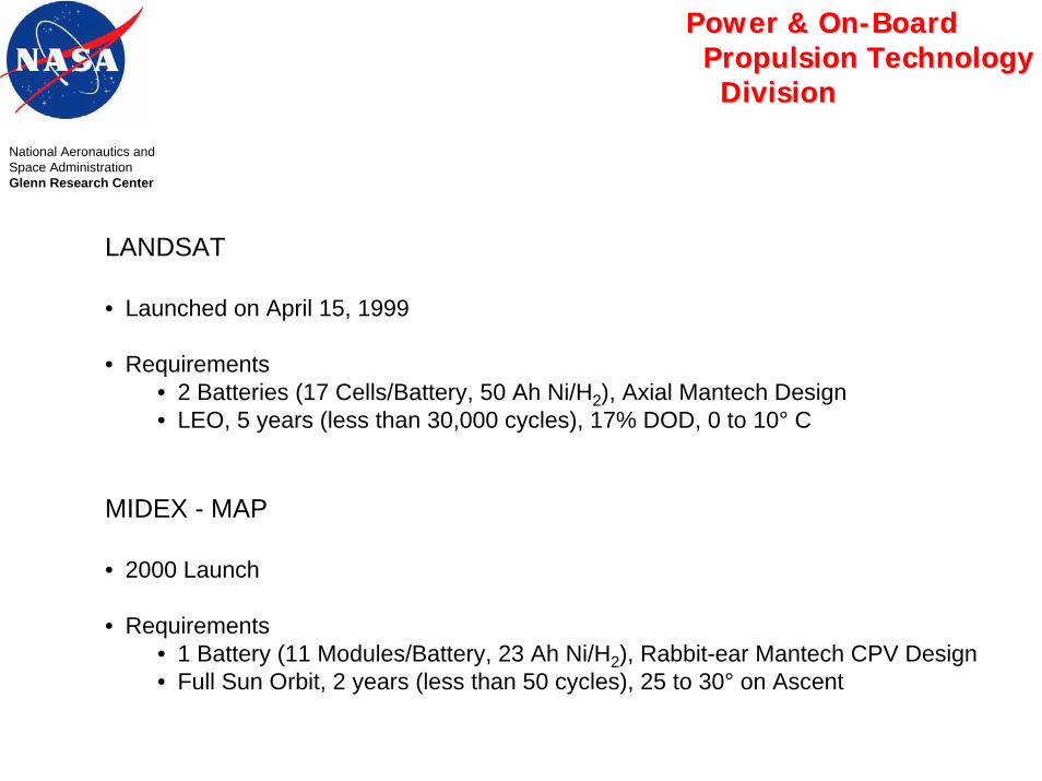
LANDSAT
• Launched on April 15, 1999
• Requirements• 2 Batteries (17 Cells/Battery, 50 Ah Ni/H2), Axial Mantech Design• LEO, 5 years (less than 30,000 cycles), 17% DOD, 0 to 10° C
MIDEX - MAP
• 2000 Launch
• Requirements• 1 Battery (11 Modules/Battery, 23 Ah Ni/H2), Rabbit-ear Mantech CPV Design• Full Sun Orbit, 2 years (less than 50 cycles), 25 to 30° on Ascent

Power & OnPower & On--BoardBoardPropulsion TechnologyPropulsion Technology
DivisionDivision
National Aeronautics andSpace AdministrationGlenn Research Center
MIDEX-IMAGE
• February 2000 Launch
• Requirements• 1 Battery (22 Cells/Battery, 21 Ah Super Ni/Cd)• LEO, 2 years (700 cycles), 0 to 25°
POES - NOAA-L, -M, -N, & -N’ Spacecraft
• Requirements• 3 Batteries per spacecraft (17 Cells/Battery, 40 Ah Ni/Cd)• LEO/Polar, 2 years (Design), 3 years (Goal), 0 to 21% DOD, 5° C

Power & OnPower & On--BoardBoardPropulsion TechnologyPropulsion Technology
DivisionDivision
National Aeronautics andSpace AdministrationGlenn Research Center
SMEX - WIRE
• Launched on March 1999
• Requirements• 1 Battery (22 Cells/Battery, 9 Ah Super Ni/Cd)• LEO, Sun-Synchronous, 4 months, 0 to 25° C
TDRS
• April 2000 TDRS H Launch
• Requirements for H, I, and J• 1 Battery (3 8-Cell Packs and 1 5-Cell Pack/Battery, 110 Ah Ni/H2), Axial Mantech Design• GEO, 15 years, max 73% DOD with 3 failed cells, 5° C
TRIANA
• September 2000 Launch
• Requirements • 1 Battery (22 Cells, 9 Ah Super Ni/Cd Cells) • Libration Point, 2 years (5 years goal), one to three times 60% DOD during launch and standby
thereafter, 0 to 10° C


Power & OnPower & On--BoardBoardPropulsion TechnologyPropulsion Technology
DivisionDivision
MAJOR FACTORS AFFECTING BATTERY LIFENational Aeronautics andSpace AdministrationGlenn Research Center
• TEMPERATURE (including uniformity for cells in series)• Accelerated degradation
• DEPTH-OF-DISCHARGE• Stresses on cell internals increase with DOD• Heat generation and peak temp increase with DOD• Charge rate (& related stresses) increases with DOD
• CHARGE CONTROL METHODOLOGY• High recharge ratios (high charge rates during overcharge)
places high stresses on cell internals• Adequate recharge ratio to ensure best available voltage and capacity

Power & OnPower & On--BoardBoardPropulsion TechnologyPropulsion Technology
DivisionDivision
BATTERY WEAROUT FAILURENational Aeronautics andSpace AdministrationGlenn Research Center
• FAILURE TO SUPPORT MISSION ABOVE MINIMUM VOLTAGE DUE TO:• Lost access to active materials• High resistance conduction path to available active material
• LOST ACCESS RESULTS FROM:• Active material migration• Fracture or corrosion of substrate• Causes - High current rates and DOD
- High overcharge rates- Electrolyte starvation
• HIGH RESISTANCE RESULTS FROM:• Expansion of nickel electrode• Narrowing of electrolyte channels• Redistribution of active material (increased path length)• Composition changes in active material• Narrowing of electrolyte channels• Causes - Poor electrode design
- High current rates and DOD- Insufficient reconditioning- Electrolyte starvation


Power & OnPower & On--BoardBoardPropulsion TechnologyPropulsion Technology
DivisionDivision
BATTERY EFFICIENCYNational Aeronautics andSpace AdministrationGlenn Research Center
ROUNDTRIP EFFICIENCY• Net watt-hour efficiency per charge/discharge cycle
Total Watt-hours delivered by batteryTotal Watt-hours delivered by battery during recharge
• Composed of simultaneously integrated• Coulombic efficiency profile
• Recharge parasitic reactions
• Voltage efficiency profile• Discharge/Charge voltage ratio
• Maintenance (trickle) charge• Energy needed to maintain recharge state
=


Derivation of the Orbital Average Heat Load Equation
ENERGY IN – ENERGY OUT= INEFFICIENCY (HEAT)
kW-min in - kW-min out = kWthermal x orbit length, min
Battery Watt-hour efficiency = Energy out = kW-min out Energy in kW-min in
kW-min in = kW-min out Battery efficiency
kW-min out – kW-min out = kWthermal x orbit length, min Battery efficiency
kW-min out[ 1 -1 ] = kWthermal x orbit length, min Battery Efficiency
kW-min out = Eclipse power x eclipse time (integrated) PMAD efficiency
Eclipse power x eclipse time (integrated) [ 1 - 1 ] = kWthermal PMAD efficiency x orbit length Battery Efficiency
National Aeronautics andSpace AdministrationGlenn Research Center
Power & OnPower & On--BoardBoardPropulsion TechnologyPropulsion Technology
DivisionDivision

National Aeronautics andSpace AdministrationGlenn Research Center
Power & OnPower & On--BoardBoardPropulsion TechnologyPropulsion Technology
DivisionDivision
Safety Consideration for Batteries
• Electrical shock
• Short circuit
• Electrolyte leakage
• Reaction by-products and contamination
• Explosion & pressure vessel design MIL-STD 1522
• Charge control

Power & OnPower & On--BoardBoardPropulsion TechnologyPropulsion Technology
DivisionDivision
TYPICAL AEROSPACE BATTERY VERIFICATION PROGRAMNational Aeronautics andSpace AdministrationGlenn Research Center
FUNCTIONAL PERFORMANCE• Capacity and voltage• Charge/discharge cyclic stability• Peak load capability
ENVIRONMENTAL PERFORMANCE• MIL-STD 1540• Thermal/vacuum including critical pressure• Vibration, shock, acceleration
LIFE CAPABILITY CERTIFICATION• Cycle life• Storage life• Pressure vessel life and safety
BATTERY SYSTEM DEMONSTRATION • System performance characterization• Mission simulation• Operational phase support

SAMPLE ACCEPTANCE TEST SEQUENCE
STEP DESCRIPTION TEMP CHARGE TIME (HRS) DISCHARGE RATE RESIDUAL CAPACITYNo. (to 1.000 volts) (to 0.50 volts)
°C C C/2 C/4 C/10 2C C/1.71 C/2 C/1O
1 Condition (2 cycles) 10 16 X X
2 Capacity (1 cycle) 20 16 X X
3 Capacity (1 cycle) 10 16 X X
4 Chg Retention (1 cycle) 10 16 X X
5 Capacity (1 cycle) 0 16 X X
SAMPLE ACCEPTANCE TEST REQUIREMENTS
Minimum Cell Group Maximum GroupTemperature Capacity (Ah) Minimum Charge Max Voltage
Condition °C 26%KOH 31%KOH Capacity Range Voltage Range
Capacity 0 +3 0.925 C 1.12 C 0.09 C 1.58 V 35 mV
Capacity 10 +3 0.925 C 1.10 C 0.09 C 1.54 V 35 mV
Capacity 20 +3 0.827 C 0.93 C 0.09 C 1.52 V 35 mV
National Aeronautics andSpace AdministrationGlenn Research Center
Power & OnPower & On--BoardBoardPropulsion TechnologyPropulsion Technology
DivisionDivision

SAMPLE CHARACTERIZATION TEST MATRIX
STEP DESCRIPTION DISCHARGE RATE RESIDUAL CAPNo. TEMP CHARGE TIME (HRS) (to 1.000 volts) (to 0.500 volts)
°C C C/2 C/4 C/10 2C 1.4C C C/2 C/1O
1 Condition (2 cycles) 10 16 X X
2 Capacity (1 cycle) 10 2 6 X X
3 Capacity (1 cycle) 10 2 6 X X
4 Capacity (1 cycle) 10 2 6 X X
5 Capacity (1 cycle) 10 2 6 X X
Note: The characterization is repeated at different charge rates and different temperatures to thoroughly mapthe performance of the cell.
National Aeronautics andSpace AdministrationGlenn Research Center
Power & OnPower & On--BoardBoardPropulsion TechnologyPropulsion Technology
DivisionDivision

Unit Acceptance Test Baseline MIL STD 1540
Test ReferencePara-graph
SuggestedSequence
Electrical &Electronics
Anten-na
MMA SolarArray
Battery Valve orPropulsionComponent
PressureVessel or
Component
Thrus-ter
Ther-mal
Opti-cal
StructuralComponent
Inspection1 4.5 1 R R R R R R R R R R RFunctional1 7.4.1 3 R R R R R R R R R R -Leakage3 7.4.9 4,7,12 R - R - R R R O O - -Shock 7.4.6 5 O4 - - - - - - - - 0 -
Vibration 7.4.4 6 R R5 R R5 R8 O R R R R5 -Acoustic 7.4.5 6 O R5 - R5 - - - - - R5 -Thermal cycle 7.4.2 8 R - - - - - - - - - -Thermal Vac 7.4.3 9 R2 O R7 O R8 R O R R R O
Wear-in 7.4.10 2 - - R - - R - R - - -Proof pressure 7.4.8 10 - - O - O R R O - - -Proof Load 7.4.7 11 - - - - - - - - - - O6
EMC 7.4.11 13 O - - - - - - - - - -
All vehicle qualification requirements to be specified by the procuring agency (4.1).Symbols (10.2.1.3) indicate the following:
R = baseline requirement (high probability of being required)O = "other" (low probability of being required; 3.5.4)- = not required (negligible probability of being required).
Notes: 1. Required before and after each test as appropriate. Include special tests as applicable (6.2).2. Discretionary for sealed or low-powered components.3. Applicable only to sealed or pressurized components4. Required when shock levels are high.5. Either vibration or acoustic, whichever is more appropriate, with the other discretionary6. Test required if composite materials are used. The test maybe omitted if proven nodestructiveevaluation methods are used with well-established acceptance and reject criteria.7. Excluding hydraulic components for launch vehicles.8. Not required for batteries that cannot be recharged after testing..

Unit Qualification Test Baseline MIL-STD 1540
Test ReferenceParagraph
SuggestedSequence
Electrical&
Electronics
Antenna MMA SolarArray
Battery Valve orPropulsionComponent
PressureVessel or
Component
Thrus-ter
Ther-mal
Opti-cal
StructuralComponent
Inspection1 4.5 1 R R R R R R R R R R RFunctional1 6.4.1 2 R R R R R R R R R R RLeakage2 6.4.7 3,6,12 R - R - R R R O O - -Shock 6.4.6 4 R 04 04 04 04 04 0 04 04 04 0
Vibration 6.4.6 5 R R5 R R5 R R R R R R5 O7
Acoustic 6.4.5 5 O R5 - R5 - - - - - R5 -Acceleration 6.4.9 7 O R O O O - O - - R -Thermalcycle
6.4.2 8 R - - - - - - - - - -
Thermal Vac 6.4.3 9 R R R R R R O R R R O
Climatic 6.4.12 10 O O O O O O O O O O -Proof 6.4.8 11 O - O - O R R R O - -Pressure3
EMC 6.4.11 13 R O O - O - - - - - -Life 6.4.10 14 O O O O R O R8 R O O O8
Burst3 6.4.8 15 O - - - O O R O O - -
All vehicle qualification requirements to be specified by the procuringagency (4.1).Symbols (10.2.1.3) indicate the following:
R = baseline requirement (high probability of being required)O = "other" (low probability of being required; 3.5.4)- = not required (negligible probability of being required).
Notes: 1. Required before and follwing each test as appropriate. Includespecial tests as applicable (6.2).
2. Required when component is sealed or pressurized.3. Required when component is pressurized4. Required when maximum expected shock spectrum in g's
exceeds 0.8 times the frequency in Hz.5. Either vibration or acoustic test required, whichever is more
appropriate, with the other discretionary6. For pressure vessels, test per MIL-STD-1522. For pressurecomponents, other than bellow and other flexible fluid devices orlines, life tests are discretionary.7. Test required if the structural component has a low margin for
fatique, or is not subjected to a static strength qualification test (6.4.4.6).8. For pressurized structures, the pressure cycle test (6.4.8.2b and
6.4.8.3c) shall be required.

Power & OnPower & On--BoardBoardPropulsion TechnologyPropulsion Technology
DivisionDivision
MAIN BATTERY VERIFICATION CONSIDERATIONSAND ISSUES
National Aeronautics andSpace AdministrationGlenn Research Center
LIFE CERTIFICATION• Limited available battery cycle life data base• Insufficient development time to demonstrate life• No validated techniques for high-fidelity accelerated LEO testing• Approach: Tests at various hardware fidelities combined with analysis
PRESSURE VESSEL SAFETY AND LIFE VERIFICATION• Permanently manned, maintainable environment• Hydrogen environment embrittlement concerns• Leak before burst design
LOCATION AND SCOPE OF LIFE TESTS• Replication, duplication of tests, and fidelity of test hardware complement

Power & OnPower & On--BoardBoardPropulsion TechnologyPropulsion Technology
DivisionDivision
BATTERY SYSTEM DEMONSTRATIONNational Aeronautics andSpace AdministrationGlenn Research Center
PURPOSE• Verify battery system compliance with mission requirements• Validate performance projections, operating plans and constraints• Characterize parameter interrelationships for system model• Evaluate mission scenarios and trouble-shoot real-time system problems
SCOPE• Conduct battery system test with simulated conditions• Test conditions and objectives will be updated during the program
RECOMMENDATIONS• A mission simulation test should be conducted to verify the battery system• Prototype battery assemblies and power electronics should be used

Power & OnPower & On--BoardBoardPropulsion TechnologyPropulsion Technology
DivisionDivision
SPACECRAFT BATTERY PERFORMANCENational Aeronautics andSpace AdministrationGlenn Research Center
PERFORMANCE IS A FUNCTION OF THE COMBINED EFFECTS OF• Individual battery design• Power System and Thermal System dynamics• Specific operational uses
ELECTRICAL AND ENERGY STORAGE CHARACTERISTICS DEPEND ON• Temperature profile/range• Current profile/range• Recharge method• Age/prior battery use

Spacecraft Energy Storage Design
Consider a spacecraft with the following design parameters:
LEO mission with 55 minutes of sunlight and 35 minutes of eclipseService life of 5 years with a uniform energy storage temperature of +100C2 kW continuous load including contingency with a minimum bus voltage of 22.5 voltsAssume that the satellite has two independent busses that equally share the loads
Compare Ni-Cd, Ni-H2, and Li-ion battery options for the satellite.
Assume a single open circuit failure of one cell and a by-pass diode voltage drop of 0.7 volts.
Ni-Cd Design
Vmin bus discharge= (N-1) VEOL - VBy-Pass
Assume an end-of-life voltage of 1.1 volts / cell22.5 volts =(N-1) 1.10 - 0.7
N=22 cells in series for the battery
5 years in LEO = 16 cycles x 365 days x 5 years = 29,200 LEO cycles day year
National Aeronautics andSpace AdministrationGlenn Research Center
Power & OnPower & On--BoardBoardPropulsion TechnologyPropulsion Technology
DivisionDivision

From the McDermott Ni-Cd model:
LEO cycle life = 1500(67-T)e-(0.038xDOD) where T is in 0C
29,200 LEO cycles = 1500(67-10)e-(0.038xDOD)
DOD = 28% Therefore, use 25% DOD as a guideline for cycle life estimate from the model
By using a Weibull shape parameter of β=12, one may scale the 10 cell Ni-Cd testing database to thedesired 22 cell satellite design by using the following relationship:
Cycle lifedesign= Cycle lifetest[Ntest/Ndesign]1/β
Since [Ntest/Ndesign]1/β = [10 /22 ]1/12 = 0.936
Cycle lifedesign= Cycle life @25% DOD x 0.936
Cycle lifedesign= 33,066 x 0.936 = 30, 950 cycles = 5.3 years
The power required by each bus would be one-half the total power (i.e. 1000W). Therefore, eachbattery needs to supply 1000W of power for the 35 minute eclipse.
National Aeronautics andSpace AdministrationGlenn Research Center
Power & OnPower & On--BoardBoardPropulsion TechnologyPropulsion Technology
DivisionDivision

The required ampere-hour capacity of the battery cell C is given by:
C = Power x time Vmin bus discharge x DOD
C = 1000W x 35 min x hr = 103.7 ampere-hours ~ 100 ampere-hours22.5 V x 0.25 x 60 min
Discharge rate @ EOL = 1000W = 44.4 amps =C/2.25 22.5 V
Recharge rates
Ampere-hours charged= ampere-hours discharged x recharge ratio
= 25.9 ampere-hours x 1.10
= 28.49 Ah
Assume a constant current charge
I = 28.49 Ah x 60 min x 1 . =31.09 amps = C/3.2Hr 55 min
National Aeronautics andSpace AdministrationGlenn Research Center
Power & OnPower & On--BoardBoardPropulsion TechnologyPropulsion Technology
DivisionDivision

Ni-H2 Design
Vmin bus discharge= (N-1) VEOL - VBy-Pass
Assume an end-of-life voltage of 1.1 volts / cell22.5 volts =(N-1) 1.10 - 0.7
N=22 cells in series for the battery
5 years in LEO = 16 cycles x 365 days x 5 years = 29,200 LEO cycles day year
From the Green-Hoffman Ni-H2 model:
LEO cycle life = 1885.04e-(0.038xDOD) for10 0C
29,200 LEO cycles = 1885.04e-(0.038xDOD)
DOD = 40.7% Therefore, use 40% DOD as a guideline for cycle life estimate from the model
By using a Weibull shape parameter of β=12, one may scale the 10 cell Ni-H2 testing database tothe desired 22 cell satellite design by using the following relationship:
Cycle lifedesign= Cycle lifetest[Ntest/Ndesign]1/β
Since [Ntest/Ndesign]1/β = [10 /22 ]1/12 = 0.936
National Aeronautics andSpace AdministrationGlenn Research Center
Power & OnPower & On--BoardBoardPropulsion TechnologyPropulsion Technology
DivisionDivision

Cycle lifedesign= Cycle life @40% DOD x 0.936
Cycle lifedesign= 30,160 x 0.936 = 28,230 cycles ~ 5 years
The power required by each bus would be one-half the total power (i.e. 1000W). Therefore, eachbattery needs to supply 1000W of power for the 35 minute eclipse.
The required ampere-hour capacity of the battery cell C is given by:
C = Power x time Vmin bus discharge x DOD
C = 1000W x 35 min x hr = 64.8 ampere-hours ~ 65 ampere-hours22.5 V x 0.40 x 60 min
Discharge rate @ EOL = 1000W = 44.4 amps =C/1.46 22.5 V
National Aeronautics andSpace AdministrationGlenn Research Center
Power & OnPower & On--BoardBoardPropulsion TechnologyPropulsion Technology
DivisionDivision

National Aeronautics andSpace AdministrationGlenn Research Center
Power & OnPower & On--BoardBoardPropulsion TechnologyPropulsion Technology
DivisionDivision
Recharge rates
Ampere-hours charged= ampere-hours discharged xrecharge ratio
= 25.9 ampere-hours x 1.08
= 27.97 Ah
Assume a constant current charge
I = 27.97 Ah x 60 min x 1 . =30.51 amps = C/2.13Hr 55 min

Li-Ion
Vmin bus discharge= (N-1) VEOL - VBy-Pass
Assume an end-of-life voltage of 2.8 volts / cell22.5 volts =(N-1) 2.80 - 0.7
N=9.28 ? 10 cells in series for the batteryCurrently no predictive LEO cycle life model exists for aerospace Li-ion battery systems.Assume 50% DOD provides 5 year life in LEO.
The power required by each bus would be one-half the total power (i.e. 1000W). Therefore, eachbattery needs to supply 1000W of power for the 35 minute eclipse.
National Aeronautics andSpace AdministrationGlenn Research Center
Power & OnPower & On--BoardBoardPropulsion TechnologyPropulsion Technology
DivisionDivision
The required ampere-hour capacity of the battery cell C is given by:
C = Power x time Vmin bus discharge x DOD
C = 1000W x 35 min x hr = 47.6 ampere-hours ~ 50 ampere-hours24.5 V x 0.50 x 60 min

National Aeronautics andSpace AdministrationGlenn Research Center
Power & OnPower & On--BoardBoardPropulsion TechnologyPropulsion Technology
DivisionDivision
Discharge rate @ EOL = 1000W = 40.8 amps =C/1.22 24.5 V
Recharge rates
Ampere-hours charged= ampere-hours discharged x recharge ratio
= 23.8 ampere-hours x 1.00
= 23.8 Ah
Assume a constant current charge
I = 23.8 Ah x 60 min x 1 . = 25.9 amps = C/1.93Hr 55 min

National Aeronautics andSpace AdministrationGlenn Research Center
Power & OnPower & On--BoardBoardPropulsion TechnologyPropulsion Technology
DivisionDivisionDesign Summary
# Cells DOD Amp-HrCapacity
Dischg.Rate
Chg.Rate
Ni-Cd 22 25% 100 C/2.25 C/3.2
Ni-H2 22 40% 65 C/1.46 C/2.13
Li-ion 10 50% 50 C/1.22 C/1.93