batch drying
TRANSCRIPT

stream that is extracted by the vacuum pump. Therefore, it is essential to in-sert a dust filter between the dryer and the condenser to prevent the passage of particles to the condenser and into the pump. The filter has to fulfill three main tasks:• Separate and collect around 99.9% or
more of the particles from the vapor• Be chemically resistant to solvents
and the dust• Minimize pressure drop to maintain
the vacuum inside the dryerTwo types of surface-layer-formation dust filters are used in drying technol-ogy: metallic filter cartridges and fabric filters. Although fabric filters are less expensive than metallic filters, they can normally collect particles only as small as 10µm, versus 1 µm or less for metallic types. However, fabric filters can also achieve 1-µm separation when given a surface treatment, such as a membrane coating.
It is important to provide sufficient filter surface to minimize pressure drop.
The required surface area can be cal-culated by using empirical maximum vapor flowrates through the filter media (fabric filters, 100 m3/m2-h; metal filters, 300 m3/m2-h) and through the vapor pip-ing. Sophisticated filter equations that include such parameters as vapor dust load (grams per cubic meter) and maxi-mum pressure drop can be used for cal-culation, but have the disadvantage of requiring hard-to-obtain product data.
Over time, the product dust forms a layer on the filter. In many applications, the layer acts like an absorbent — it be-comes wet from the vapors and particles tend to build a crusty layer that blocks the pores of the filter. This reduces the vapor flow and can cause a dramatic drop in the drying speed (Figure 11).
To avoid this problem, it is necessary to clean the filter regularly by blow-back with pressurized gas. Initiation of the blowback cycle may be triggered when the pressure rises to a predeter-mined level (usually 30–70 mbars), by a specific elapsed time, or by a combina-
tion of these methods. Time-con-trolled filter blowback is often more efficient than the pressure drop-controlled method because it is done at regular intervals and is less disruptive to the dry-ing process. For example, at low vacuum levels (below 100 mbars), it is important not to blow back too often, in order to avoid loss of dryer vacuum caused by the blow-back gas.
For dust filters used for ac-tive pharmaceutical ingredients (API), the following limit values have shown to be useful for cal-culating and checking filter sur-faces:• 25 m/s maximum vapor speed
in vapor line• 0.5–3.0 g/m3 maximum
estimated vapor dust load• 100 m3/m2-h maximum
flowrate for textile filter cloth • 300 m3/m2-h maximum
flowrate for metallic filters
CondensersCondensers are used mostly to recover valuable process solvents, which are evap-orated during drying. They are typically shell-and-tube type surface condensers, arranged either vertically or horizontally. Condensers used with dryers are oper-ated in a different manner from those used for other evaporation applications, in that the vapors are usually condensed inside the tubes instead of outside. The advantage is that the tubes are easier to clean, provided that straight tube bundles are used instead of U-tube bundles.
Besides recovering solvent, condens-ers assist the drying process in the fol-lowing ways:• The great reduction of vapor volume
creates its own suction effect, thus helping to achieve a deeper process vacuum in the dryer
• Removal of the vapor has a buffering effect on the vacuum pump, thereby enabling the drying process to oper-ate closer to a steady-state condition
• Reduction of the vapor load on the vacuum pump permits the use of a smaller-sized pump, whose main task is to maintain vacuum and re-move inerts
• Condensate collection can be mea-sured and combined with a mass balance to allow indirect, real-time monitoring of product moisture dur-ing the drying process
While most of the vapor is removed upstream of the vacuum pump, an after-condenser is often located on the discharge side of the pump to recover additional solvent. Condensers are often supplied with collection vessels for condensate. The collection vessel should be drained periodically to avoid reboiling. As an additional precaution, it may also be jacketed to keep it cold.
Depending on the type of vapors (sol-vents) that must be condensed during the drying process, condensers have to cover a wide range of solvent proper-ties. Cooling media include cold water, glycol-water mixtures, and various thermal fluids.
Design criteria are:• Easy cleaning — In case of a process
upset or product changeover, condenser tubes should be readily cleanable by solvent flush or manual “rodding”
• Low fouling — Carryover of solids or liquid droplets in the vapor stream should be avoided to minimize depos-its on the inner tube wall
• Avoidance of the accumulation of inert gases, which can reduce the ef-fective tube area for condensation.
In the design and operation of a con-denser, it is important to take into ac-count the nature of the solvent that has to be handled. When the solvent changes from the vapor phase to liquid, there is a dramatic decrease in volume. The spe-cific vapor volume strongly depends on the liquid boiling point at the condenser pressure (Figure 12).
Solvents that have different boiling
points produce different vapor volumes, with resultant different vapor velocities in the piping to the condenser and the pump. Speed limits have to be kept in mind to assure total condensation for full recovery of solvents.
For example, consider a typical dry-ing operation for a sensitive product that is wet with a solvent, such as eth-anol, that is to be dried at 50°C, and a condenser designed for this process. If the system is later required to dry a similar, but water-wet, product at the same rate, the difference in molecular weight and the vacuum required will produce vapor volumes (and there-fore tube velocities) that are six times larger (Figure 12). This illustrates the importance of designing the condenser for the most severe case likely to be en-countered. Additionally, coolant tem-peratures have to be chosen carefully for total condensation.
Some guidelines for proper design and operation ranges are:• Coolant return temperatures from
the condenser should be at least 5°C below the boiling point of liquids (which is also the condensation tem-perature) at condenser pressure
• Summer/winter operation modes must often be taken into consider-ation, especially if river water is used for cooling
• A vapor speed limit of approximately 25 m/s should be set in the condenser tubes
Final wordsIn summary, while careful selection of an appropriate dryer is the key element, peripheral equipment plays an impor-tant role in a successful drying result. No matter how appropriate the dryer for the application, the potential always exists to improve efficiency by adjusting the pe-ripherals to the machine and the process.
Also, a sophisticated control system ensures that all parameters come to-gether by combining relevant process data with peripherals and machine data. Feedback about product changes during the drying process can be trans-ferred into well-defined operational ad-justments of the dryer and its peripher-als. Thus the whole drying process can be operated more reliably, repetitively and safely. ■
Edited by Gerald Ondrey
����������������������������
� �� �� �� �������������������
���
�����
����
����
����
����
� ���
������������
������������������������������������������������������������
FIGURE 12. As the chart shows, specific vapor volume [m3/kg] and liquid boiling point have a significant impact on the success of a drying process
AuthorsReiner Laible is process technology manager for Rosen-mund VTA AG, a member of De Dietrich Process Systems (Gestadeckplatz 6, CH-4410, Liestal, Switzerland; Phone: +41-61-9251-695; Fax: +41-61-9251-699; Email: [email protected]). He joined Rosenmund VTA in 1995 as head of the Dryer Pilot Plant Laboratory. In his
current position since 2002 he is also responsi-ble for drying technology and process design at Rosenmund. Previously (1983–1988), he worked in thermal-process design for thermal seawater desalination plants, and later (1989–1994) on process design of thin-film evaporators. He holds a Ph.D. in chemical engineering from the Tech-nical University of Munich, Germany, and is an affiliate of VDI (the professional association of engineers in Germany).
Mark Lattman is a con-sulting engineer for De Di-etrich Process Systems, Inc. (DDPS; 9110 Forsyth Park Drive, Charlotte, N.C. 28273; Phone: 704-587-5312; Fax: 704-588-6866; E-mail: [email protected]). He is responsible for testing, pro-cess design, scaleup, and trou-bleshooting of batch-filtration and drying equipment. He
worked for Rosenmund Inc. (now part of DDPS) from 1983 to 2005. Previously (1977–1982), he did process development and plant-assistance engineering for a company in the specialty chemical and food industries. Lattman received his B.S. in chemical engineering from the State University of New York at Buffalo, and an M.S. in chemical engineering from MIT. He has been an AIChE member since 1977.
Reprinted from the November 2005 Chemical Engineering magazine. © 2005 Access Intelligence, LLC.
FIGURE 11. A multiple-cartridge dust filter, completely blocked by solids
����
���������������
����������
���������������
�����������
�������
�������������������������
�����
�����������
������������������
�����������������
��������
������������
FIGURE 9. A typical flow diagram of a horizontal paddle dryer, showing the rela-tionships between the dryer and its peripherals: dust filter, solvent condenser/re-ceiver, heating/cooling unit and vacuum system
FIGURE 7. In addition to drying, the conical screw dryer can be used for powder-blending, reactions and crystallization
FIGURE 8. The geometry of a spherical dryer makes it relatively easy to clean-in-place
�����
�����
�����������
�������
�����
�������������
FIGURE 10. Heating and cooling of jacketed dryers. Top: Heating or cooling source fluid is sent directly to the dryer jacket. Bottom: A thermal fluid circulates through the dryer jacket and is heated or cooled via heat exchangers

very fact that it can perform multiple operations. However, these additional features come at a price, as a filter/dryer loses some of its heat-transfer ca-pability with the substitution of a filter plate for a solid base.Conical screw dryer: The conical screw dryer (Figure 7) is a vertically oriented, conically shaped vessel whose walls slope inward to a central outlet at the bottom. It has an agitator that is typically top-driven and forms an inverted “L”, whereby the screw arm is positioned close to the vessel wall. On most models, the complete agitator as-sembly rotates, along with the screw arm, providing excellent mixing of the solid and continual movement across the heated walls.
A special feature of this type of dryer is that it, too, can be used for more than just drying. Its other capabilities include powder-blending, crystalliza-tion, extraction, and alkalization and other reactions. Conical screw dryers can perform well for a wide range of products, but can cause size degrada-tion when used for drying crystals. The conical shape of the vessel promotes easy solids discharge.
Because of its versatility, this dryer design is favored in many industries. However, the screw can be difficult to clean in place.Spherical dryer: A spherical dryer con-sists of a machined sphere fitted with ei-ther a top- or bottom-mounted agitator, the latter having a shape specially de-signed to conform to the spherical wall. The solids outlet is at the very bottom of the sphere, thus allowing almost com-plete product discharge (Figure 8). The outlet is typically sealed by a full port ball valve that incorporates a metal-to-metal seal.
The agitator provides excellent solids mixing and contact with the heated wall surface. This results in good heat transfer and drying times, even though the spheri-cal geometry gives this dryer a low ratio of heated wall area to enclosed volume.
On the other hand, the spherical
shape makes the dryer relatively easy to clean-in-place and the cleaning liq-uid is easily drained out. The geometry also results in a small footprint with respect to installation. In general, the spherical dryer is ideally suited to the drying of pharmaceuticals and other high-value solids.
Optimizing the drying processTo optimize dryer performance, it is im-portant to adjust the peripheral equip-ment to match the specific needs of the drying operation. This equipment, as noted above, includes the dryer’s heat-ing and cooling system, the dust filter, the condenser and the vacuum pump (Figure 9).
These units make critical contribu-tions to the success of the drying pro-cess. Process problems such as lump formation or crust buildup can actually be compounded by incorrect adjust-ment of the peripherals. Overall, an electronic control system can ensure that every item of equipment can run under optimal conditions.
Heating/cooling unitsHeat-transfer fluid is typically cir-culated from a heating/cooling skid that is connected to the plant’s main steam or pressurized-water system. Two types of arrangement are possible with jacketed batch dryers: direct fluid heating or indirect heating via primary and secondary circuits (Figure 10).
In direct fluid heating, steam or ther-mal liquids are directly supplied to the dryer jacket from the source, which may be a boiler or chiller. More often, indirect systems are used, in which a thermal liquid such as water, a glycol-water mixture, or thermal oil circulates through the dryer jacket. This liquid passes through heat exchangers that respectively transfer the heat from the heat source (typically steam) or remove heat into the coolant (Figure 10).
Advantages of indirect heating/cool-ing are:• Flexibility and precision in control-
ling temperatures• Buffering against temperature fluc-
tuations in the source To calculate the required heating/cool-ing capacity required for a batch dryer, the following factors must be consid-ered: • Energy to heat mass of dryer and
dust filter = Qm• Energy to heat mass of heating media
inside the coils = Qh• Energy to heat mass of wet product,
including solvent = Qpr• Energy for evaporation of solvent
= Qs• Heat loss by radiation• Type of solvent• Cleaning procedure (possibly liquid
evaporation)• Dryer efficiency• The dryer’s material of construction
(for example, stainless steel)The total energy required Qtotalis thus:
Qtotal = Qm + Qh + Qpr + Qs + Qloss
The following special cases may apply:• If the cleaning procedure involves
evaporation/reflux of solvent, the re-sultant heat load may be greater than the total energy calculated above for the drying process and may become the design basis of the heat transfer unit
• Sensitive products may require rapid cooling at the end of the drying step to maintain product quality, so care must be taken not to undersize the cooling capacity.
In summary, the total energy require-ment should be viewed as a set of in-fluences that are interdependent. In particular, when a sensitive product is involved, it is prudent to base energy calculations on experience or test data as much as possible.
Dust filterDuring the drying process, the prod-uct tends to become dusty and dust particles are entrained in the vapor
handled. On the other hand, the agita-tor requires seals at both ends, and this aspect of design, operation and mainte-nance is critical for the successful opera-tion of the dryer.
Discharge of the dried solid is typi-cally via an outlet in the bottom of the cylindrical shell or from the bottom of one of the circular end faces.
Achieving total discharge of the solid is typically not possible, but discharge can be improved by tilting the vessel slightly toward the discharge end and shaping the paddles so that they move solids to-ward the outlet. A paddle dryer tends to require a relatively large footprint for in-stallation in order to have room to access and remove the agitator (Figure 3).Disc dryer: A disc dryer (Figure 4) consists of a vessel shell encompassing a tubular rotor, which can be mounted in the vertical or horizontal plane. At-tached to the rotor are a series of discs, set at an angle to the rotor. Heated fluid can be flowed through these discs, as well as through the rotor and the vessel walls.
Drying can be performed under pres-sure or vacuum and can be achieved by convection as well as through direct
conduction from the heated surfaces, since these dryers have the capability of hot-gas blow-through. Consequently, the disc dryer is very versa-tile. It can be used to process wet cake or even slurry, in ei-ther batch or continuous mode. For continuous operation, the residence time can be adjusted from minutes to several hours.
Because the disc dryer has a high heat transfer area per unit volume, its footprint is small relative to its capacity.
However, the complexity of the dryer internals present challenges for clean-ing, so this dryer is not often applied to multi-purpose production of high-value pharmaceuticals.
This type of dryer is often used as a cooker or rendering device in the food and animal products industry. In these applications, the throughputs are gen-erally higher and the design is limited to the horizontal-rotor form.Pan dryer: A pan dryer consists of a cir-cular, pressure-rated vessel with a flat or conical-shaped bottom. An agitator, often heated, is top or bottom-mounted, the former configuration being preferred for most fine-chemical and pharmaceu-tical applications because it eliminates dead spots where product can accumu-late. Heated jackets are provided on the vessel sidewall and base. The top head of the vessel can also be heated, thereby reducing the likelihood of solvent con-densing on this surface during the dry-ing operation.
The top-mounted agitator is provided with both rotational and translational (up and down) movement. The latter fea-ture saves wear and tear on the agitator during startup by raising it sufficiently
above the wet solids to reduce viscous resistance. It also reduces the initial load on the motor. A bottom-driven pan dryer does not have agitator transla-tional movement, but the short distance between the gearbox and the agitator blades makes for much greater torque.
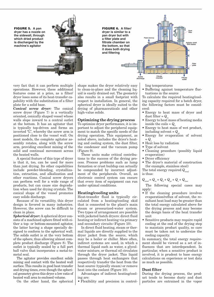
As in the case of a paddle dryer, the agitator for a pan dryer provides good mixing and efficient contact between the product and the heated vessel surfaces, including the agitator itself. In pan dryers, the agitator also helps discharge dried solids: A large nozzle, mounted on the sidewall, is opened, and the agitator arms push product through the opening whenever they pass by it (Figure 5).
The design of the actuating device to seal this solid discharge nozzle can take many forms, from a manual plug to a substantial, hydraulically driven valve with a metal-to-metal seal. Be-cause the agitator cannot be allowed to contact the base of the dryer (which would mean metal-to-metal contact), a certain quantity of solid, or heel, is retained in the vessel. This heel may become part of the next batch. Alterna-tively, it can be physically removed or simply washed away. Filter/dryer: In appearance, a filter/dryer is identical to a pan dryer, except that the bottom plate is replaced by a filter plate and the base has a filtrate chamber (Figure 6). The advantage of a filter/dryer is that it can perform mul-tiple operations, including filtration and washing, prior to solids drying and discharge. By filtering and washing the product, the filter/dryer avoids the chal-lenging task of charging wet cake to the dryer, since wet cake is not pumpable. The primary reason the filter/dryer is chosen over other dryer types is the
Cover Story
Drying is one of the more com-mon and important operations in the manufacture of chemi-cal products, since it is used in practically every plant that makes solid products in the
form of powder and granules. Drying is often required at various stages of a process, for the removal of moisture or solvents from feedstocks, intermediate products and the final products.
Equipment used for drying falls into two basic categories: direct dryers and indirect dryers. In direct drying, a warm or hot gas stream (usually air or an inert gas) is applied directly to the product and the operation is typically continuous. In contrast, indirect dry-ing is a batch (or continuous) operation in which the product is contained in a sealed vessel and heated by a hot fluid that circulates through a jacket around the vessel.
Indirect batch drying, the subject of this article, is used for products made in small or medium-sized batches (up to approximately 6,000 L) and that are liable to be contaminated or degraded by exposure to the atmosphere, or chemicals that should not be released to the environment because they are toxic or hazardous. Such products in-clude pharmaceuticals, photochemicals, agricultural chemicals, explosives, and various specialty chemicals.
Batch drying is an important ele-ment in the manufacture of chemical and pharmaceutical products. Besides drying the product, it recovers process solvents, which may be recycled to the plant. Also, dryers strongly influence overall production times. A typical pro-duction train consists of reactors, evapo-rators, filters/centrifuges and, finally, dryers (the last step before the final product is discharged and packaged). Drying is typically the most time-con-suming step, so the efficiency of the drying process significantly affects the overall efficiency of the plant.
Successful drying depends not only on correct selection of the dryer type it-
self, but also on the optimal adjustment of peripheral equipment associated with the dryer. Peripherals include the heating and cooling system used with the dryer, a condenser, a vacuum pump, and a dust filter to prevent product particles from reaching the condenser or pump. Details on the roles of periph-eral equipment are presented later in this article.
The basics While indirect dryers vary in design and method of operation, they have some common elements. All are sealed vessels, heated by a heat-transfer fluid that circulates through heating coils on the vessel wall. Since these dryers are mostly used for fine chemicals, they are generally made of stainless steel or higher-grade alloys.
Most batch dryers may be run ei-ther under vacuum or under pressure, but they are almost always run under vacuum to save energy, minimize the drying temperature, and protect opera-tors and the environment. Liquid (usu-ally process solvent) is evaporated from the wet product by heating the solvent above its boiling point corresponding to the absolute pressure. The vapor is pulled toward the vacuum pump and re-covered by a condenser located between the dryer and the pump. Recovery of the liquid also reduces the load on the pump. In some cases (such as those involving flammable products) the dryer may be purged during the drying process by an inert gas, such as nitrogen. Dryers typi-cally have a dust filter to prevent par-ticles from passing to the condenser and the vacuum pump.
Indirect dryer typesThere are various criteria for differenti-ating the types of indirect dryers that are available. For a start, batch dryers may be oriented vertically or horizontally. A dryer may also be selected according to the flow pattern of the product during the drying process. For example, some dryers, such as double-cone dryers, em-
ploy a rotating vessel, while others have agitators, high-speed mixers and baffles to move and mix the product. Dryer ef-ficiency varies widely, depending on the machine’s design and the nature of the internal equipment.Conical (double-cone) tumble dryer: One of the simplest and least expensive dryers is the conical tumble dryer (Figure 1). It can take many variations in shape, but its basic form is true to its name. The dryer is mounted on a horizontal axis for the drying operation and rotates fully through 360 deg. Like other batch dry-ers, it has a heated wall, and a vacuum is applied to remove vapor. When drying is complete, the machine is moved to a ver-tical position for discharge of the dried solids from a nozzle at the bottom of the cone.
The tumbling action generally pro-vides good mixing and regular contact between the solids and the heated wall. However, while tumbling is ideal for free-flowing materials, those that tend to agglomerate can form lumps or balls, which are not only undesirable but also complicate the discharge operation.
This dryer can be provided in a num-ber of materials of construction, includ-ing glass-lined steel — a popular option, as the glass lining provides some non-stick property and corrosion resistance. The fact that the entire dryer rotates requires a relatively large installation footprint and some access restriction for safety reasons. Paddle dryer: Like the conical dryer, the paddle dryer operates in the hori-zontal plane, but it consists of a cylin-drical vessel and is equipped with a horizontal centrally located agitator that has multiple paddles and is sup-ported at both ends. Heating fluid is in many cases circulated through the agi-tator as well as through the vessel wall (Figure 2).
The action of the agitator makes for efficient mixing of the product and good contact with all the heated surfaces. Since the agitator is supported at both ends, high-shear or lumpy solids can be
Batch Drying: The ‘Indirect’ Solution to Sensitive Drying Problems
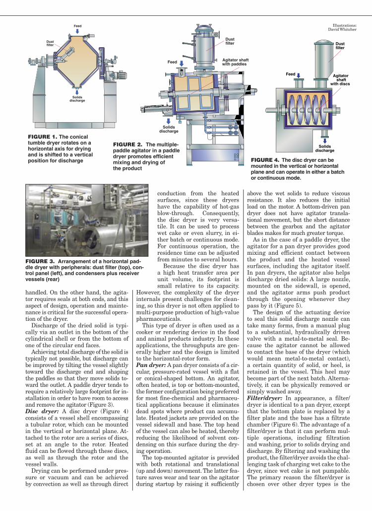
FIGURE 1. The conical tumble dryer rotates on a horizontal axis for drying and is shifted to a vertical position for discharge
FIGURE 2. The multiple-paddle agitator in a paddle dryer promotes efficient mixing and drying of the product
����
���������������
����������
����
���������������
����������������������������
����������
����
���������������
��������������
������������
����������
Illustrations: David Whitcher
FIGURE 4. The disc dryer can be mounted in the vertical or horizontal plane and can operate in either a batch or continuous mode.
FIGURE 3. Arrangement of a horizontal pad-dle dryer with peripherals: dust filter (top), con-trol panel (left), and condensers plus receiver vessels (rear)
Guidelines on specifying an indirect dryer and peripheral equipment for sensitive or hazardous chemicals
Mark Lattman and Reiner Laible, De Dietrich, Process Systems
FIGURE 5. A pan dryer has a nozzle on the sidewall, through which dried product is discharged by the machine’s agitator
�������������
���������������
��������������� ��������
������
�����������
�������������������������
����������
FIGURE 6. A filter/dryer is similar to a pan dryer but with a filter plate and filtrate chamber on the bottom, so that it does both drying and filtering
very fact that it can perform multiple operations. However, these additional features come at a price, as a filter/dryer loses some of its heat-transfer ca-pability with the substitution of a filter plate for a solid base.Conical screw dryer: The conical screw dryer (Figure 7) is a vertically oriented, conically shaped vessel whose walls slope inward to a central outlet at the bottom. It has an agitator that is typically top-driven and forms an inverted “L”, whereby the screw arm is positioned close to the vessel wall. On most models, the complete agitator as-sembly rotates, along with the screw arm, providing excellent mixing of the solid and continual movement across the heated walls.
A special feature of this type of dryer is that it, too, can be used for more than just drying. Its other capabilities include powder-blending, crystalliza-tion, extraction, and alkalization and other reactions. Conical screw dryers can perform well for a wide range of products, but can cause size degrada-tion when used for drying crystals. The conical shape of the vessel promotes easy solids discharge.
Because of its versatility, this dryer design is favored in many industries. However, the screw can be difficult to clean in place.Spherical dryer: A spherical dryer con-sists of a machined sphere fitted with ei-ther a top- or bottom-mounted agitator, the latter having a shape specially de-signed to conform to the spherical wall. The solids outlet is at the very bottom of the sphere, thus allowing almost com-plete product discharge (Figure 8). The outlet is typically sealed by a full port ball valve that incorporates a metal-to-metal seal.
The agitator provides excellent solids mixing and contact with the heated wall surface. This results in good heat transfer and drying times, even though the spheri-cal geometry gives this dryer a low ratio of heated wall area to enclosed volume.
On the other hand, the spherical
shape makes the dryer relatively easy to clean-in-place and the cleaning liq-uid is easily drained out. The geometry also results in a small footprint with respect to installation. In general, the spherical dryer is ideally suited to the drying of pharmaceuticals and other high-value solids.
Optimizing the drying processTo optimize dryer performance, it is im-portant to adjust the peripheral equip-ment to match the specific needs of the drying operation. This equipment, as noted above, includes the dryer’s heat-ing and cooling system, the dust filter, the condenser and the vacuum pump (Figure 9).
These units make critical contribu-tions to the success of the drying pro-cess. Process problems such as lump formation or crust buildup can actually be compounded by incorrect adjust-ment of the peripherals. Overall, an electronic control system can ensure that every item of equipment can run under optimal conditions.
Heating/cooling unitsHeat-transfer fluid is typically cir-culated from a heating/cooling skid that is connected to the plant’s main steam or pressurized-water system. Two types of arrangement are possible with jacketed batch dryers: direct fluid heating or indirect heating via primary and secondary circuits (Figure 10).
In direct fluid heating, steam or ther-mal liquids are directly supplied to the dryer jacket from the source, which may be a boiler or chiller. More often, indirect systems are used, in which a thermal liquid such as water, a glycol-water mixture, or thermal oil circulates through the dryer jacket. This liquid passes through heat exchangers that respectively transfer the heat from the heat source (typically steam) or remove heat into the coolant (Figure 10).
Advantages of indirect heating/cool-ing are:• Flexibility and precision in control-
ling temperatures• Buffering against temperature fluc-
tuations in the source To calculate the required heating/cool-ing capacity required for a batch dryer, the following factors must be consid-ered: • Energy to heat mass of dryer and
dust filter = Qm• Energy to heat mass of heating media
inside the coils = Qh• Energy to heat mass of wet product,
including solvent = Qpr• Energy for evaporation of solvent
= Qs• Heat loss by radiation• Type of solvent• Cleaning procedure (possibly liquid
evaporation)• Dryer efficiency• The dryer’s material of construction
(for example, stainless steel)The total energy required Qtotalis thus:
Qtotal = Qm + Qh + Qpr + Qs + Qloss
The following special cases may apply:• If the cleaning procedure involves
evaporation/reflux of solvent, the re-sultant heat load may be greater than the total energy calculated above for the drying process and may become the design basis of the heat transfer unit
• Sensitive products may require rapid cooling at the end of the drying step to maintain product quality, so care must be taken not to undersize the cooling capacity.
In summary, the total energy require-ment should be viewed as a set of in-fluences that are interdependent. In particular, when a sensitive product is involved, it is prudent to base energy calculations on experience or test data as much as possible.
Dust filterDuring the drying process, the prod-uct tends to become dusty and dust particles are entrained in the vapor
handled. On the other hand, the agita-tor requires seals at both ends, and this aspect of design, operation and mainte-nance is critical for the successful opera-tion of the dryer.
Discharge of the dried solid is typi-cally via an outlet in the bottom of the cylindrical shell or from the bottom of one of the circular end faces.
Achieving total discharge of the solid is typically not possible, but discharge can be improved by tilting the vessel slightly toward the discharge end and shaping the paddles so that they move solids to-ward the outlet. A paddle dryer tends to require a relatively large footprint for in-stallation in order to have room to access and remove the agitator (Figure 3).Disc dryer: A disc dryer (Figure 4) consists of a vessel shell encompassing a tubular rotor, which can be mounted in the vertical or horizontal plane. At-tached to the rotor are a series of discs, set at an angle to the rotor. Heated fluid can be flowed through these discs, as well as through the rotor and the vessel walls.
Drying can be performed under pres-sure or vacuum and can be achieved by convection as well as through direct
conduction from the heated surfaces, since these dryers have the capability of hot-gas blow-through. Consequently, the disc dryer is very versa-tile. It can be used to process wet cake or even slurry, in ei-ther batch or continuous mode. For continuous operation, the residence time can be adjusted from minutes to several hours.
Because the disc dryer has a high heat transfer area per unit volume, its footprint is small relative to its capacity.
However, the complexity of the dryer internals present challenges for clean-ing, so this dryer is not often applied to multi-purpose production of high-value pharmaceuticals.
This type of dryer is often used as a cooker or rendering device in the food and animal products industry. In these applications, the throughputs are gen-erally higher and the design is limited to the horizontal-rotor form.Pan dryer: A pan dryer consists of a cir-cular, pressure-rated vessel with a flat or conical-shaped bottom. An agitator, often heated, is top or bottom-mounted, the former configuration being preferred for most fine-chemical and pharmaceu-tical applications because it eliminates dead spots where product can accumu-late. Heated jackets are provided on the vessel sidewall and base. The top head of the vessel can also be heated, thereby reducing the likelihood of solvent con-densing on this surface during the dry-ing operation.
The top-mounted agitator is provided with both rotational and translational (up and down) movement. The latter fea-ture saves wear and tear on the agitator during startup by raising it sufficiently
above the wet solids to reduce viscous resistance. It also reduces the initial load on the motor. A bottom-driven pan dryer does not have agitator transla-tional movement, but the short distance between the gearbox and the agitator blades makes for much greater torque.
As in the case of a paddle dryer, the agitator for a pan dryer provides good mixing and efficient contact between the product and the heated vessel surfaces, including the agitator itself. In pan dryers, the agitator also helps discharge dried solids: A large nozzle, mounted on the sidewall, is opened, and the agitator arms push product through the opening whenever they pass by it (Figure 5).
The design of the actuating device to seal this solid discharge nozzle can take many forms, from a manual plug to a substantial, hydraulically driven valve with a metal-to-metal seal. Be-cause the agitator cannot be allowed to contact the base of the dryer (which would mean metal-to-metal contact), a certain quantity of solid, or heel, is retained in the vessel. This heel may become part of the next batch. Alterna-tively, it can be physically removed or simply washed away. Filter/dryer: In appearance, a filter/dryer is identical to a pan dryer, except that the bottom plate is replaced by a filter plate and the base has a filtrate chamber (Figure 6). The advantage of a filter/dryer is that it can perform mul-tiple operations, including filtration and washing, prior to solids drying and discharge. By filtering and washing the product, the filter/dryer avoids the chal-lenging task of charging wet cake to the dryer, since wet cake is not pumpable. The primary reason the filter/dryer is chosen over other dryer types is the
Cover Story
Drying is one of the more com-mon and important operations in the manufacture of chemi-cal products, since it is used in practically every plant that makes solid products in the
form of powder and granules. Drying is often required at various stages of a process, for the removal of moisture or solvents from feedstocks, intermediate products and the final products.
Equipment used for drying falls into two basic categories: direct dryers and indirect dryers. In direct drying, a warm or hot gas stream (usually air or an inert gas) is applied directly to the product and the operation is typically continuous. In contrast, indirect dry-ing is a batch (or continuous) operation in which the product is contained in a sealed vessel and heated by a hot fluid that circulates through a jacket around the vessel.
Indirect batch drying, the subject of this article, is used for products made in small or medium-sized batches (up to approximately 6,000 L) and that are liable to be contaminated or degraded by exposure to the atmosphere, or chemicals that should not be released to the environment because they are toxic or hazardous. Such products in-clude pharmaceuticals, photochemicals, agricultural chemicals, explosives, and various specialty chemicals.
Batch drying is an important ele-ment in the manufacture of chemical and pharmaceutical products. Besides drying the product, it recovers process solvents, which may be recycled to the plant. Also, dryers strongly influence overall production times. A typical pro-duction train consists of reactors, evapo-rators, filters/centrifuges and, finally, dryers (the last step before the final product is discharged and packaged). Drying is typically the most time-con-suming step, so the efficiency of the drying process significantly affects the overall efficiency of the plant.
Successful drying depends not only on correct selection of the dryer type it-
self, but also on the optimal adjustment of peripheral equipment associated with the dryer. Peripherals include the heating and cooling system used with the dryer, a condenser, a vacuum pump, and a dust filter to prevent product particles from reaching the condenser or pump. Details on the roles of periph-eral equipment are presented later in this article.
The basics While indirect dryers vary in design and method of operation, they have some common elements. All are sealed vessels, heated by a heat-transfer fluid that circulates through heating coils on the vessel wall. Since these dryers are mostly used for fine chemicals, they are generally made of stainless steel or higher-grade alloys.
Most batch dryers may be run ei-ther under vacuum or under pressure, but they are almost always run under vacuum to save energy, minimize the drying temperature, and protect opera-tors and the environment. Liquid (usu-ally process solvent) is evaporated from the wet product by heating the solvent above its boiling point corresponding to the absolute pressure. The vapor is pulled toward the vacuum pump and re-covered by a condenser located between the dryer and the pump. Recovery of the liquid also reduces the load on the pump. In some cases (such as those involving flammable products) the dryer may be purged during the drying process by an inert gas, such as nitrogen. Dryers typi-cally have a dust filter to prevent par-ticles from passing to the condenser and the vacuum pump.
Indirect dryer typesThere are various criteria for differenti-ating the types of indirect dryers that are available. For a start, batch dryers may be oriented vertically or horizontally. A dryer may also be selected according to the flow pattern of the product during the drying process. For example, some dryers, such as double-cone dryers, em-
ploy a rotating vessel, while others have agitators, high-speed mixers and baffles to move and mix the product. Dryer ef-ficiency varies widely, depending on the machine’s design and the nature of the internal equipment.Conical (double-cone) tumble dryer: One of the simplest and least expensive dryers is the conical tumble dryer (Figure 1). It can take many variations in shape, but its basic form is true to its name. The dryer is mounted on a horizontal axis for the drying operation and rotates fully through 360 deg. Like other batch dry-ers, it has a heated wall, and a vacuum is applied to remove vapor. When drying is complete, the machine is moved to a ver-tical position for discharge of the dried solids from a nozzle at the bottom of the cone.
The tumbling action generally pro-vides good mixing and regular contact between the solids and the heated wall. However, while tumbling is ideal for free-flowing materials, those that tend to agglomerate can form lumps or balls, which are not only undesirable but also complicate the discharge operation.
This dryer can be provided in a num-ber of materials of construction, includ-ing glass-lined steel — a popular option, as the glass lining provides some non-stick property and corrosion resistance. The fact that the entire dryer rotates requires a relatively large installation footprint and some access restriction for safety reasons. Paddle dryer: Like the conical dryer, the paddle dryer operates in the hori-zontal plane, but it consists of a cylin-drical vessel and is equipped with a horizontal centrally located agitator that has multiple paddles and is sup-ported at both ends. Heating fluid is in many cases circulated through the agi-tator as well as through the vessel wall (Figure 2).
The action of the agitator makes for efficient mixing of the product and good contact with all the heated surfaces. Since the agitator is supported at both ends, high-shear or lumpy solids can be
Batch Drying: The ‘Indirect’ Solution to Sensitive Drying Problems
FIGURE 1. The conical tumble dryer rotates on a horizontal axis for drying and is shifted to a vertical position for discharge
FIGURE 2. The multiple-paddle agitator in a paddle dryer promotes efficient mixing and drying of the product
����
���������������
����������
����
���������������
����������������������������
����������
����
���������������
��������������
������������
����������
Illustrations: David Whitcher
FIGURE 4. The disc dryer can be mounted in the vertical or horizontal plane and can operate in either a batch or continuous mode.
FIGURE 3. Arrangement of a horizontal pad-dle dryer with peripherals: dust filter (top), con-trol panel (left), and condensers plus receiver vessels (rear)
Guidelines on specifying an indirect dryer and peripheral equipment for sensitive or hazardous chemicals
Mark Lattman and Reiner Laible, De Dietrich, Process Systems
FIGURE 5. A pan dryer has a nozzle on the sidewall, through which dried product is discharged by the machine’s agitator
�������������
���������������
��������������� ��������
������
�����������
�������������������������
����������
FIGURE 6. A filter/dryer is similar to a pan dryer but with a filter plate and filtrate chamber on the bottom, so that it does both drying and filtering

stream that is extracted by the vacuum pump. Therefore, it is essential to in-sert a dust filter between the dryer and the condenser to prevent the passage of particles to the condenser and into the pump. The filter has to fulfill three main tasks:• Separate and collect around 99.9% or
more of the particles from the vapor• Be chemically resistant to solvents
and the dust• Minimize pressure drop to maintain
the vacuum inside the dryerTwo types of surface-layer-formation dust filters are used in drying technol-ogy: metallic filter cartridges and fabric filters. Although fabric filters are less expensive than metallic filters, they can normally collect particles only as small as 10µm, versus 1 µm or less for metallic types. However, fabric filters can also achieve 1-µm separation when given a surface treatment, such as a membrane coating.
It is important to provide sufficient filter surface to minimize pressure drop.
The required surface area can be cal-culated by using empirical maximum vapor flowrates through the filter media (fabric filters, 100 m3/m2-h; metal filters, 300 m3/m2-h) and through the vapor pip-ing. Sophisticated filter equations that include such parameters as vapor dust load (grams per cubic meter) and maxi-mum pressure drop can be used for cal-culation, but have the disadvantage of requiring hard-to-obtain product data.
Over time, the product dust forms a layer on the filter. In many applications, the layer acts like an absorbent — it be-comes wet from the vapors and particles tend to build a crusty layer that blocks the pores of the filter. This reduces the vapor flow and can cause a dramatic drop in the drying speed (Figure 11).
To avoid this problem, it is necessary to clean the filter regularly by blow-back with pressurized gas. Initiation of the blowback cycle may be triggered when the pressure rises to a predeter-mined level (usually 30–70 mbars), by a specific elapsed time, or by a combina-
tion of these methods. Time-con-trolled filter blowback is often more efficient than the pressure drop-controlled method because it is done at regular intervals and is less disruptive to the dry-ing process. For example, at low vacuum levels (below 100 mbars), it is important not to blow back too often, in order to avoid loss of dryer vacuum caused by the blow-back gas.
For dust filters used for ac-tive pharmaceutical ingredients (API), the following limit values have shown to be useful for cal-culating and checking filter sur-faces:• 25 m/s maximum vapor speed
in vapor line• 0.5–3.0 g/m3 maximum
estimated vapor dust load• 100 m3/m2-h maximum
flowrate for textile filter cloth • 300 m3/m2-h maximum
flowrate for metallic filters
CondensersCondensers are used mostly to recover valuable process solvents, which are evap-orated during drying. They are typically shell-and-tube type surface condensers, arranged either vertically or horizontally. Condensers used with dryers are oper-ated in a different manner from those used for other evaporation applications, in that the vapors are usually condensed inside the tubes instead of outside. The advantage is that the tubes are easier to clean, provided that straight tube bundles are used instead of U-tube bundles.
Besides recovering solvent, condens-ers assist the drying process in the fol-lowing ways:• The great reduction of vapor volume
creates its own suction effect, thus helping to achieve a deeper process vacuum in the dryer
• Removal of the vapor has a buffering effect on the vacuum pump, thereby enabling the drying process to oper-ate closer to a steady-state condition
• Reduction of the vapor load on the vacuum pump permits the use of a smaller-sized pump, whose main task is to maintain vacuum and re-move inerts
• Condensate collection can be mea-sured and combined with a mass balance to allow indirect, real-time monitoring of product moisture dur-ing the drying process
While most of the vapor is removed upstream of the vacuum pump, an after-condenser is often located on the discharge side of the pump to recover additional solvent. Condensers are often supplied with collection vessels for condensate. The collection vessel should be drained periodically to avoid reboiling. As an additional precaution, it may also be jacketed to keep it cold.
Depending on the type of vapors (sol-vents) that must be condensed during the drying process, condensers have to cover a wide range of solvent proper-ties. Cooling media include cold water, glycol-water mixtures, and various thermal fluids.
Design criteria are:• Easy cleaning — In case of a process
upset or product changeover, condenser tubes should be readily cleanable by solvent flush or manual “rodding”
• Low fouling — Carryover of solids or liquid droplets in the vapor stream should be avoided to minimize depos-its on the inner tube wall
• Avoidance of the accumulation of inert gases, which can reduce the ef-fective tube area for condensation.
In the design and operation of a con-denser, it is important to take into ac-count the nature of the solvent that has to be handled. When the solvent changes from the vapor phase to liquid, there is a dramatic decrease in volume. The spe-cific vapor volume strongly depends on the liquid boiling point at the condenser pressure (Figure 12).
Solvents that have different boiling
points produce different vapor volumes, with resultant different vapor velocities in the piping to the condenser and the pump. Speed limits have to be kept in mind to assure total condensation for full recovery of solvents.
For example, consider a typical dry-ing operation for a sensitive product that is wet with a solvent, such as eth-anol, that is to be dried at 50°C, and a condenser designed for this process. If the system is later required to dry a similar, but water-wet, product at the same rate, the difference in molecular weight and the vacuum required will produce vapor volumes (and there-fore tube velocities) that are six times larger (Figure 12). This illustrates the importance of designing the condenser for the most severe case likely to be en-countered. Additionally, coolant tem-peratures have to be chosen carefully for total condensation.
Some guidelines for proper design and operation ranges are:• Coolant return temperatures from
the condenser should be at least 5°C below the boiling point of liquids (which is also the condensation tem-perature) at condenser pressure
• Summer/winter operation modes must often be taken into consider-ation, especially if river water is used for cooling
• A vapor speed limit of approximately 25 m/s should be set in the condenser tubes
Final wordsIn summary, while careful selection of an appropriate dryer is the key element, peripheral equipment plays an impor-tant role in a successful drying result. No matter how appropriate the dryer for the application, the potential always exists to improve efficiency by adjusting the pe-ripherals to the machine and the process.
Also, a sophisticated control system ensures that all parameters come to-gether by combining relevant process data with peripherals and machine data. Feedback about product changes during the drying process can be trans-ferred into well-defined operational ad-justments of the dryer and its peripher-als. Thus the whole drying process can be operated more reliably, repetitively and safely. ■
Edited by Gerald Ondrey
����������������������������
� �� �� �� �������������������
���
�����
����
����
����
����
� ���
������������
������������������������������������������������������������
FIGURE 12. As the chart shows, specific vapor volume [m3/kg] and liquid boiling point have a significant impact on the success of a drying process
AuthorsReiner Laible is process technology manager for Rosen-mund VTA AG, a member of De Dietrich Process Systems (Gestadeckplatz 6, CH-4410, Liestal, Switzerland; Phone: +41-61-9251-695; Fax: +41-61-9251-699; Email: [email protected]). He joined Rosenmund VTA in 1995 as head of the Dryer Pilot Plant Laboratory. In his
current position since 2002 he is also responsi-ble for drying technology and process design at Rosenmund. Previously (1983–1988), he worked in thermal-process design for thermal seawater desalination plants, and later (1989–1994) on process design of thin-film evaporators. He holds a Ph.D. in chemical engineering from the Tech-nical University of Munich, Germany, and is an affiliate of VDI (the professional association of engineers in Germany).
Mark Lattman is a con-sulting engineer for De Di-etrich Process Systems, Inc. (DDPS; 9110 Forsyth Park Drive, Charlotte, N.C. 28273; Phone: 704-587-5312; Fax: 704-588-6866; E-mail: [email protected]). He is responsible for testing, pro-cess design, scaleup, and trou-bleshooting of batch-filtration and drying equipment. He
worked for Rosenmund Inc. (now part of DDPS) from 1983 to 2005. Previously (1977–1982), he did process development and plant-assistance engineering for a company in the specialty chemical and food industries. Lattman received his B.S. in chemical engineering from the State University of New York at Buffalo, and an M.S. in chemical engineering from MIT. He has been an AIChE member since 1977.
Reprinted from the November 2005 Chemical Engineering magazine. © 2005 Access Intelligence, LLC.
FIGURE 11. A multiple-cartridge dust filter, completely blocked by solids
����
���������������
����������
���������������
�����������
�������
�������������������������
�����
�����������
������������������
�����������������
��������
������������
FIGURE 9. A typical flow diagram of a horizontal paddle dryer, showing the rela-tionships between the dryer and its peripherals: dust filter, solvent condenser/re-ceiver, heating/cooling unit and vacuum system
FIGURE 7. In addition to drying, the conical screw dryer can be used for powder-blending, reactions and crystallization
FIGURE 8. The geometry of a spherical dryer makes it relatively easy to clean-in-place
�����
�����
�����������
�������
�����
�������������
FIGURE 10. Heating and cooling of jacketed dryers. Top: Heating or cooling source fluid is sent directly to the dryer jacket. Bottom: A thermal fluid circulates through the dryer jacket and is heated or cooled via heat exchangers