basics of microwave remote sensing - iit bombayavikb/gnr618/basics of sar remo… · ·...
TRANSCRIPT

BASICS OF MICROWAVE REMOTE SENSING
1Dr. A. Bhattacharya

Remote Sensing Fundamental
The entire range of EM radiation constitute the EM Spectrum
Microwave sensors sense electromagnetic radiations in the microwave region of the EM Spectrum
2
Dr. A. Bhattacharya
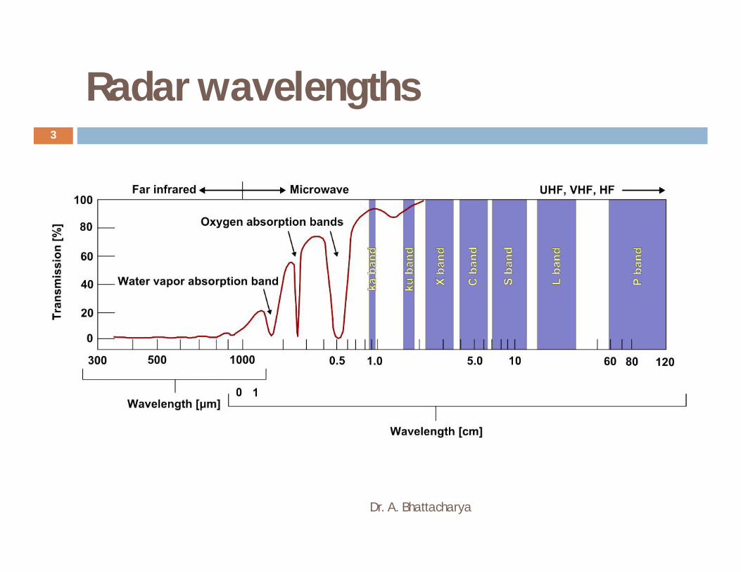
Radar wavelengths
Dr. A. Bhattacharya
3

Radar wavelengths
Dr. A. Bhattacharya
4

RADAR
Dr. A. Bhattacharya
5
Radar is an acronym for Radio Detection And Ranging. A Radar system has three primary functions:
It transmits microwave (radio) signals towards a scene It receives the portion of the transmitted energy
backscattered from the scene
It observes the strength (detection) and the time delay (ranging) of the return signals.
Radar provides its own energy source and, therefore, can operate both day or night and through cloud cover. This type of system is known as an active remote sensing system.

Characteristics of radar remote sensing
Dr. A. Bhattacharya
6
Advantages compared to optical remote sensing
All weather capability (small sensitivity of clouds, light rain) Day and night operation (independence of sun illumination) No effects of atmospheric constituents (multitemporal analysis) Sensitivity to dielectric properties (water content , biomass, ice) Sensitivity to surface roughness ( ocean wind speed) Accurate measurements of distance (interferometry) Sensitivity to man made objects Sensitivity to target structure (use of polarimetry) Subsurface penetration

Characteristics of radar remote sensing
Dr. A. Bhattacharya
7
Inconvenients
Complex interactions (difficulty in understanding, complex processing)
Speckle effects (difficulty in visual interpretation)
Topographic effects
Effect of surface roughness

All-weather system
Dr. A. Bhattacharya
8
An ‘ all-weather ’ imaging system A microwaves system: cloud penetrating capabilities

Marginal atmospheric effects
Dr. A. Bhattacharya
9
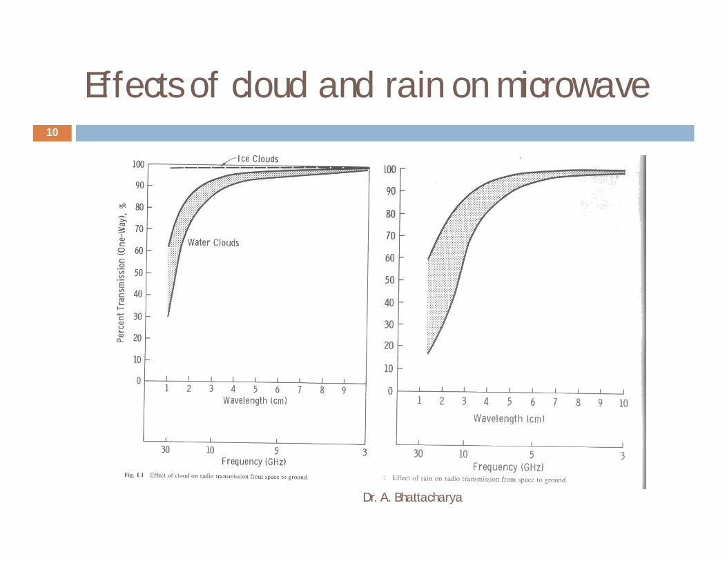
Effects of cloud and rain on microwave
Dr. A. Bhattacharya
10
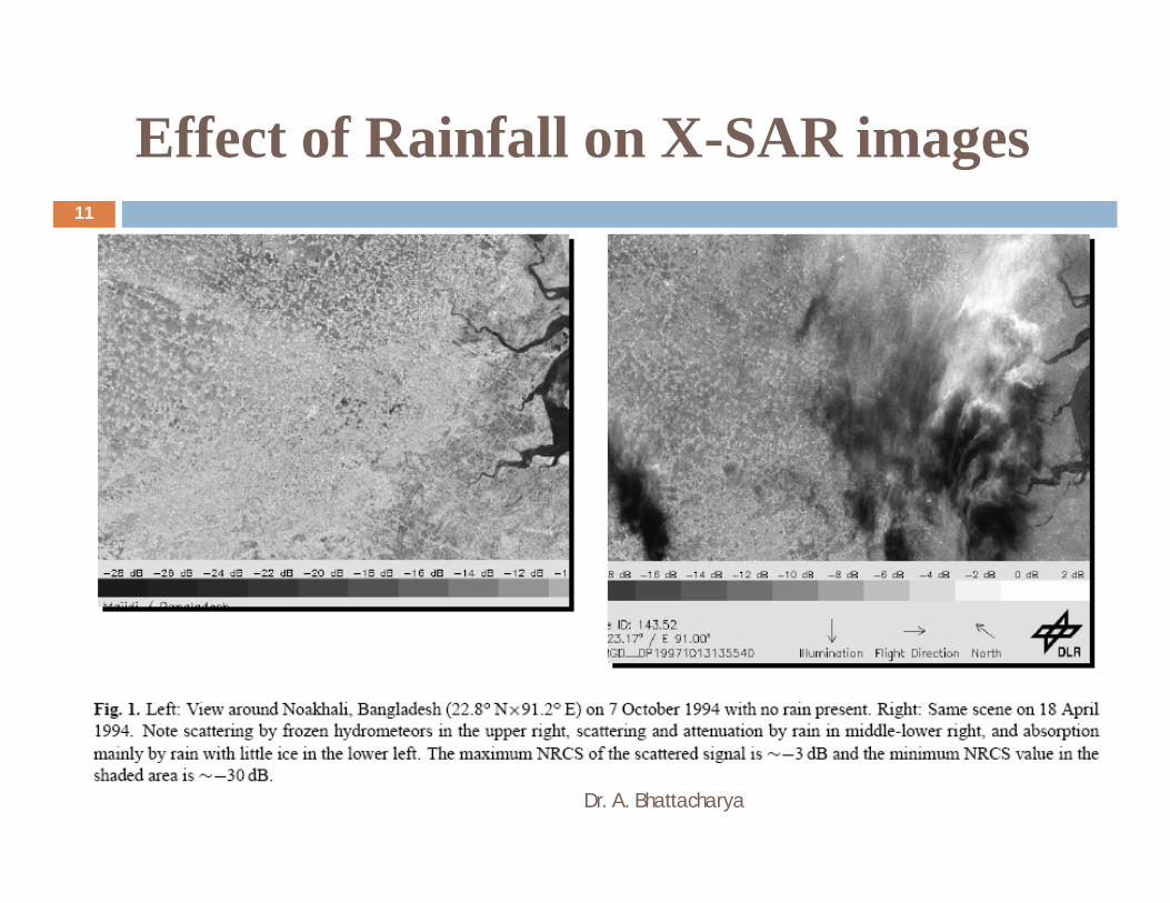
Effect of Rainfall on X-SAR images
Dr. A. Bhattacharya
11
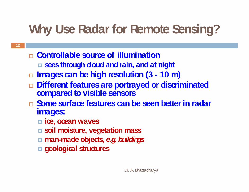
Why Use Radar for Remote Sensing?
Dr. A. Bhattacharya
12
Controllable source of illumination sees through cloud and rain, and at night
Images can be high resolution (3 - 10 m) Different features are portrayed or discriminated
compared to visible sensors Some surface features can be seen better in radar
images: ice, ocean waves soil moisture, vegetation mass man-made objects, e.g. buildings geological structures

Types of Microwave Remote Sensors
Dr. A. Bhattacharya
13
Microwave radiometers
Measure the emittance of EM energy within the microwave region of the EM spectrum, just like thermal IR sensors
– Non-imaging RADARs
1. Altimeters – measure the elevation of the earth’s surface
2. Scatterometers – detect variations in microwave backscatter from a large area - measure variations in surface roughness, used to estimate ocean wind speed
– Imaging RADARs
Synthetic Aperture Radars – map variations in microwave backscatter at fine spatial scales (10 to 50 m), used to create an image – measure variations in surface roughness and surface moisture
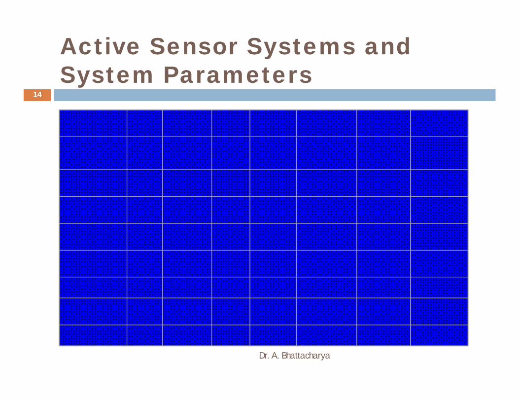
Active Sensor Systems and System Parameters
Dr. A. Bhattacharya
14
Parameters Seasat
ERS-1,2 JERS-1
Radarsat SIR-C ENVISAT Radarsat -2
Launch June1978
July 91&Apr 95
Feb.92
Nov. 95 Apr & Oct.1994
March 1, 2002
Dec. 14, 2007
Frequency(GHz)
1.275 5.3 1.275 5.3 1.2, 5.3, 9.8 5.3 5.3
Wavelength.,cm
23.5 5.6 23.5 5.6 23.5,5.6,3.1 5.6 5.6
Resolution(m) 25 30 18 10 - 100 25 30 10-100
Swath (km) 100 100 75 35 - 500 15 - 90 150–1km 35 – 500
Look angle 23 23 35 20 - 50 20 - 55 20 - 50 20 –50
Polarization HH VV HH HH HH,VV,HV HH,VV HH,VV
Looks 4 4 3 1- 4-14 1, 4

Various Imaging Modes
Dr. A. Bhattacharya
15
StripMode
ScanSAR
SpotlightResolution: 3m Resolution: 1 m
Resolution: 16 m
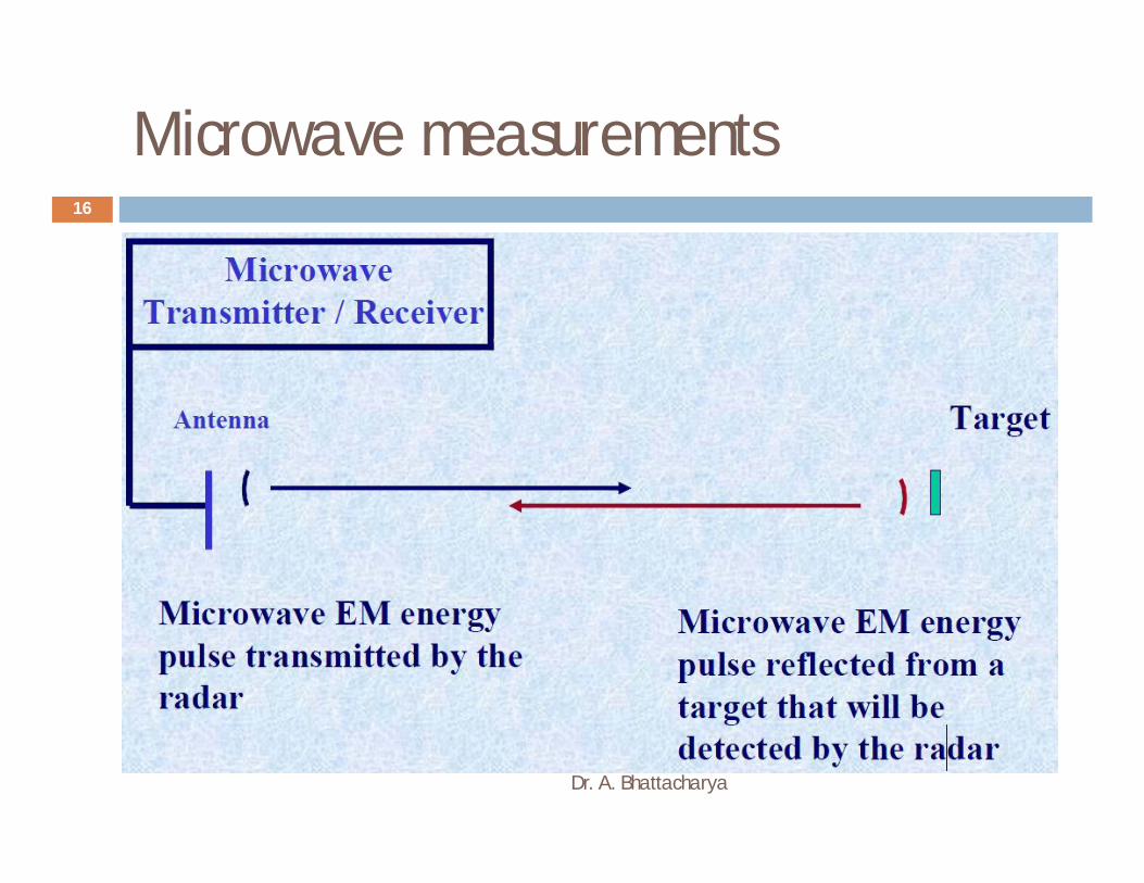
Microwave measurements
Dr. A. Bhattacharya
16
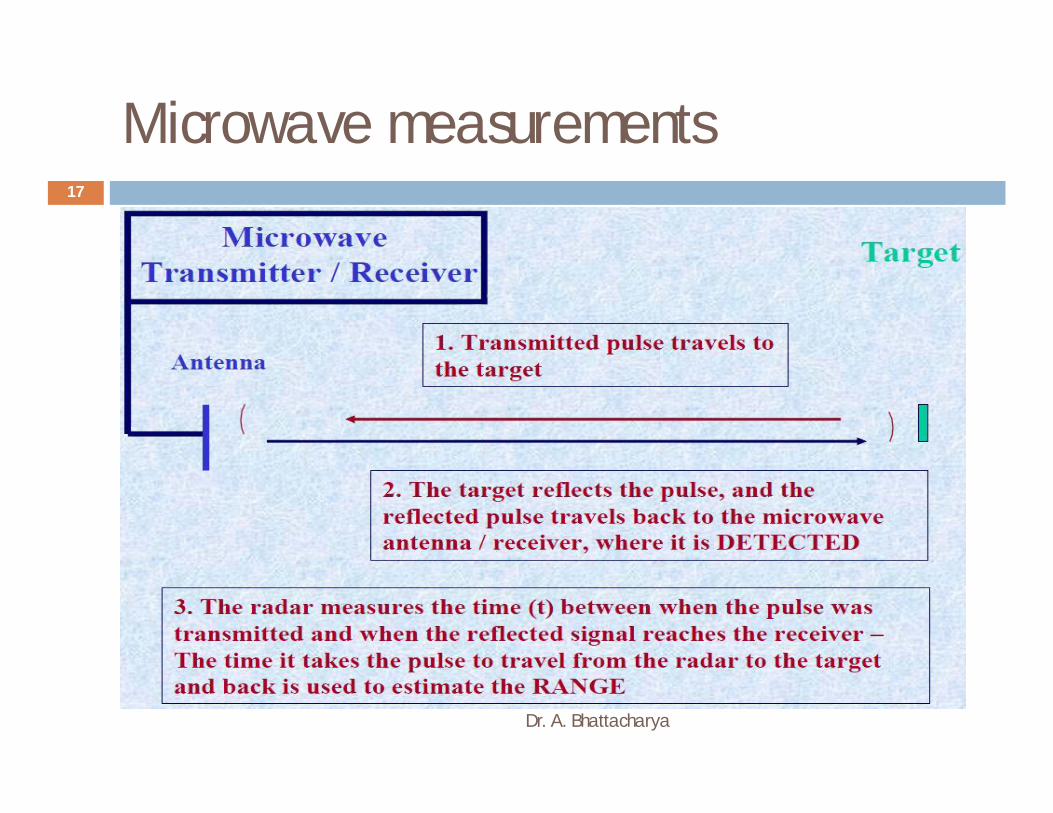
Microwave measurements
Dr. A. Bhattacharya
17
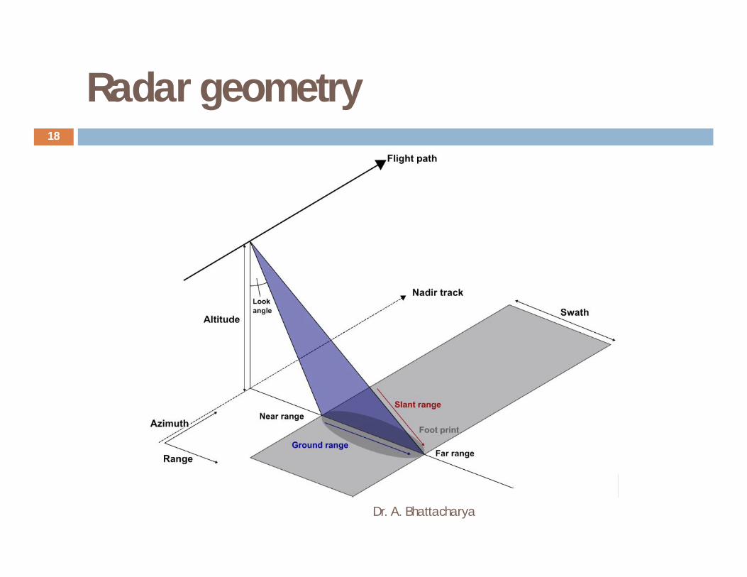
Radar geometry
Dr. A. Bhattacharya
18
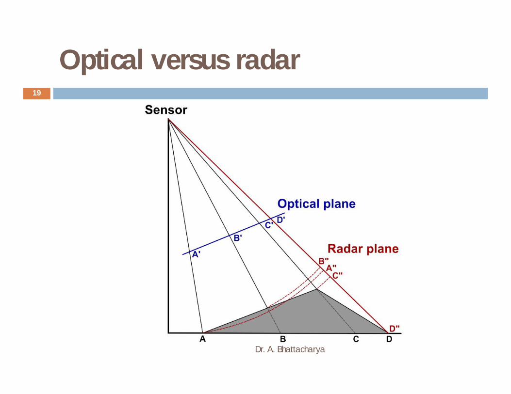
Optical versus radar
Dr. A. Bhattacharya
19

Side-Looking Radar
Dr. A. Bhattacharya
20
Resolution
Dr. A. Bhattacharya
21
Since SAR is an active system, the actual sensor resolution has two dimensions: range resolution and azimuth resolution. Resolution of a SAR sensor should not be confused with pixel spacing which results from sampling done by the SAR image processor.
Range :
Range resolution of a SAR is determined by built-in radar and processor constraints which act in the slant range domain. Range resolution is dependent on the length of the processed pulse; shorter pulses result in “higher” resolution. Radar data are created in the slant range domain, but usually are projected onto the ground range plane when processed into an image.
Azimuth :
For a real aperture radar, azimuth resolution is determined by the angular beamwidth of the terrain strip illuminated by the radar beam. For two objects to be resolved, they must be separated in the azimuth direction by a distance greater than the beam width on the ground. SAR gets its name from the azimuth processing and can achieve an azimuth resolution which may be hundreds of times smaller than the transmitted antenna beam width.

Range Resolution
Dr. A. Bhattacharya
22
The ability of the radar to distinguish two targets in the range direction.
R = c/2 = PL/2
Range and Ground Resolutions
Dr. A. Bhattacharya
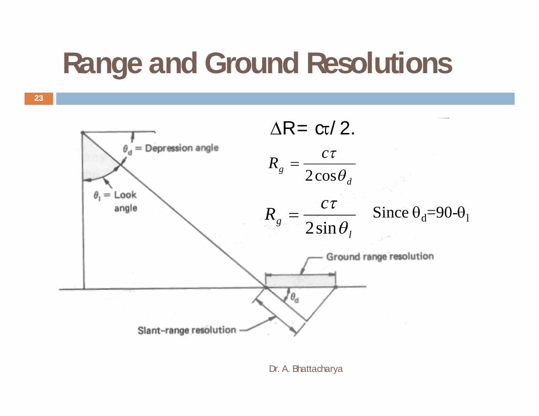
23
dg
cR
cos2
Since d=90-ll
gcR
sin2
R = c/2.
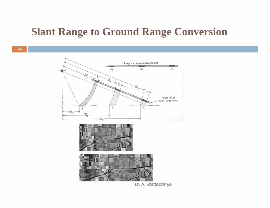
Slant Range to Ground Range Conversion
Dr. A. Bhattacharya
24
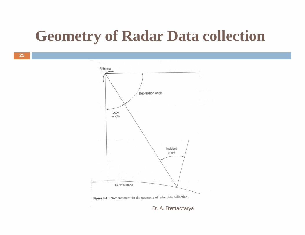
Geometry of Radar Data collection
Dr. A. Bhattacharya
25
Range Resolution (Examples)
Dr. A. Bhattacharya
26
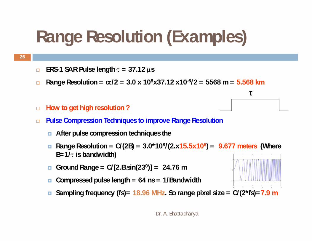
ERS-1 SAR Pulse length = 37.12 s
Range Resolution = c/2 = 3.0 x 108x37.12 x10-6/2 = 5568 m = 5.568 km
How to get high resolution ?
Pulse Compression Techniques to improve Range Resolution
After pulse compression techniques the
Range Resolution = C/(2B) = 3.0*108/(2.x15.5x106) = 9.677 meters (Where B=1/ is bandwidth)
Ground Range = C/[2.B.sin(230)] = 24.76 m
Compressed pulse length = 64 ns = 1/Bandwidth
Sampling frequency (fs)= 18.96 MHz. So range pixel size = C/(2*fs)=7.9 m

High resolution (Range)
Dr. A. Bhattacharya
27
Pulse Length = 2 s to 65 s
Bandwidth = 150 MHz nominal, 300 MHz high resolution
Range Resolution = C/(2B) = 3.0*108 /(2.x150x106 )
= 1 m (150 MHz)
and 0.5 m (300 MHz)
Azimuth Spatial Resolution
Dr. A. Bhattacharya
28
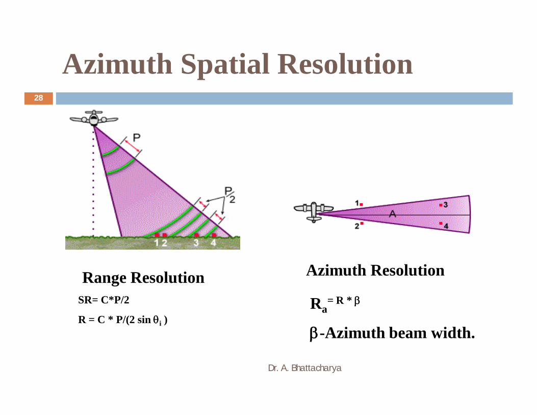
Range Resolution Azimuth Resolution
SR= C*P/2
R = C * P/(2 sin i )Ra
= R *
-Azimuth beam width.

Azimuth resolution
Dr. A. Bhattacharya
29
Elevation (θB) and Azimuth (ΦB) Beam Widths

Azimuth resolution
Dr. A. Bhattacharya
30
Elevation (θB) and Azimuth (ΦB) Beam Widths
Azimuth beam width = 0.288 deg.
Elevation beam width = 5.8 deg.

Azimuth resolution
Dr. A. Bhattacharya
31
Ra= R.
= /L
Ra = R./L
Where L is length of antenna (10 m).
R = H/cos l
For H=10 km, l= 230, =5.66 cm
Ra= 60 meters
For H=765 kmRa = 4.6978 km
Improvement in Azimuth Resolution !
Dr. A. Bhattacharya
32
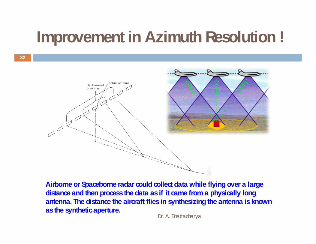
Airborne or Spaceborne radar could collect data while flying over a large distance and then process the data as if it came from a physically long antenna. The distance the aircraft flies in synthesizing the antenna is known as the synthetic aperture.
What is Synthetic Aperture Radar (SAR)?
Dr. A. Bhattacharya
33
A side-looking radar system which makes a high-resolution image of the Earth’s surface (for remote sensing applications)
As an imaging side-looking radar moves along its path, it accumulates data. In this way, continuous strips of the ground surface are “illuminated” parallel and to one side of the flight direction. From this record of signal data, processing is needed to produce radar images.
The across-track dimension is referred to as “range”. Near range edge is closest to nadir (the points directly below the radar) and far range edge is farthest from the radar.
The along-track dimension is referred to as “azimuth”.
In a radar system, resolution is defined for both the range and azimuth directions.
Digital signal processing is used to focus the image and obtain a higher resolution than achieved by conventional radar

What is a SAR image?
Dr. A. Bhattacharya
34
Synthetic Aperture Radar (SAR) Systems
Dr. A. Bhattacharya
35
A major advance in radar remote sensing has been the improvement in azimuth resolution through the development of synthetic aperture radar (SAR) systems.
In a real aperture radar system that the azimuthalresolution inversely proportional to antenna length (L)
Great improvement in azimuth resolution could be realized if a longer antenna were used.
Engineers now synthesize a very long antenna electronically. The major difference is that a greater number of additional beams are sent toward the object.
Large advantage: SAR technology allows high spatial resolution imaging

Synthetic Aperture Radar (SAR) Systems
Dr. A. Bhattacharya
36

Synthetic Aperture Radar (SAR) Systems
Dr. A. Bhattacharya
37
The Doppler principle states that the frequency (pitch) of a sound changes if the listener and/or source are in motion relative to one another.
•A doppler radar is a radar using the doppler effect of the returned echoes from targets to measure their radial velocity.
•The microwave signal sent by the radar antenna's directional beam is reflected toward the radar and compared in frequency, up or down from the original signal, measuring the target velocity component in the direction of the beam.
•An approaching train whistle will have an increasingly higher frequency pitch as it approaches. This pitch will be highest when it is directly perpendicular to the listener (receiver). This is called the point of zero Doppler. As the train passes by, its pitch will decrease in frequency in proportion to the distance it is from the listener (receiver).
•This principle is applicable to all harmonic wave motion, including the microwaves used in radar systems.

Synthetic Aperture Radar (SAR) Systems
Dr. A. Bhattacharya
38
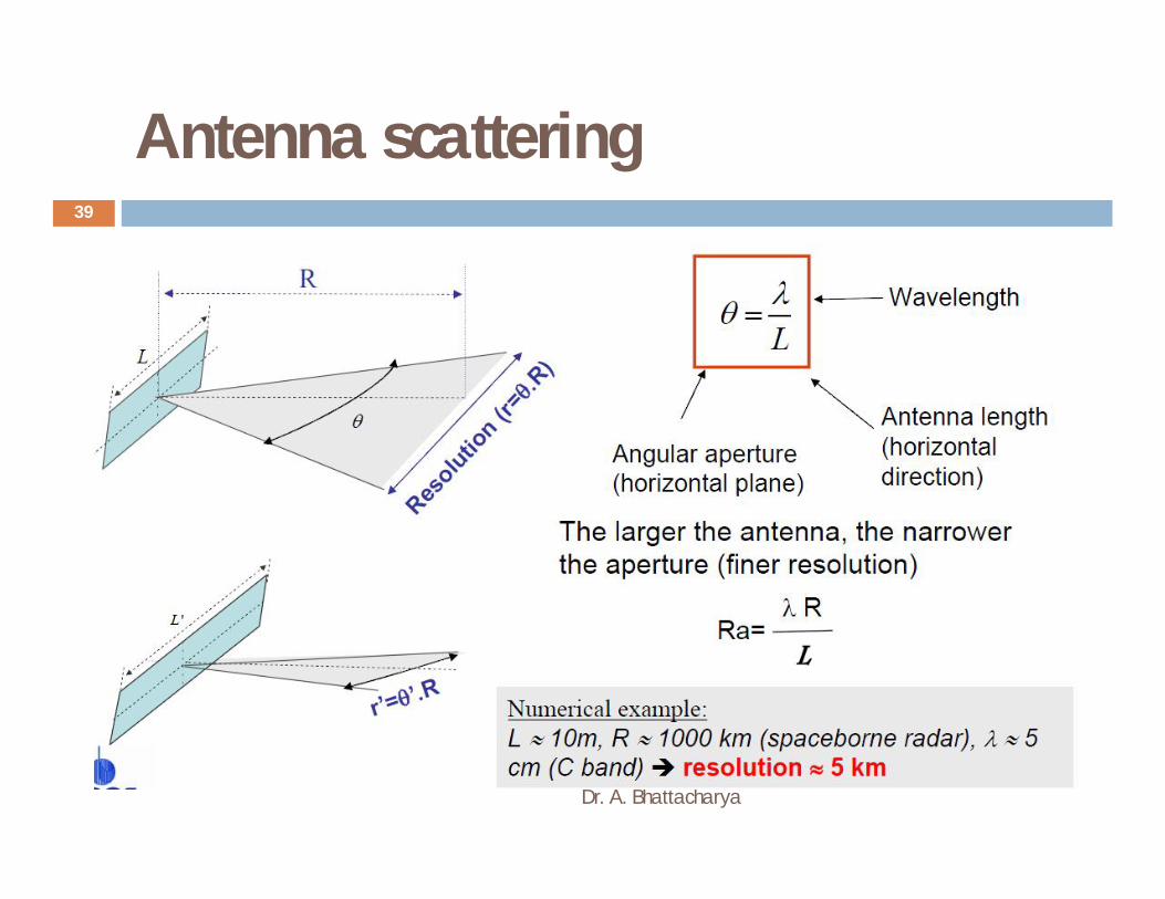
Antenna scattering
Dr. A. Bhattacharya
39
Improvement in Azimuth Resolution
Dr. A. Bhattacharya
40
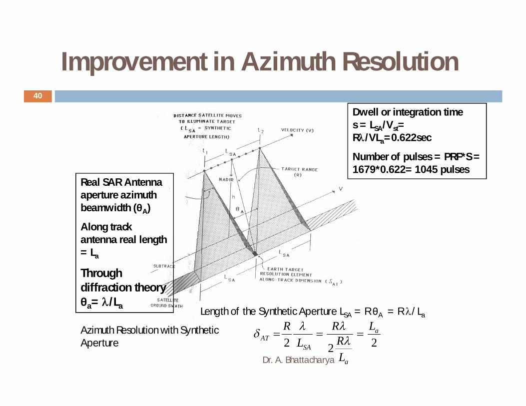
Length of the Synthetic Aperture LSA = R θA = R /La
222a
a
SAAT
L
LR
RL
R
Dwell or integration time s = LSA/Vst= R/VLa=0.622sec
Number of pulses = PRF*S = 1679*0.622= 1045 pulses
Real SAR Antenna aperture azimuth beamwidth (θA)
Along track antenna real length = La
Through diffraction theory θa= /La
Azimuth Resolution with Synthetic Aperture
Improvement in Azimuth Resolution
Dr. A. Bhattacharya
41
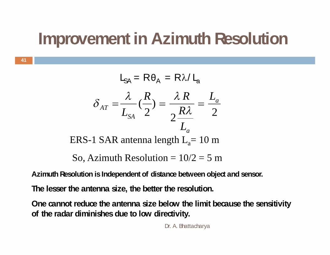
LSA = R θA = R /La
22)
2( a
a
SAAT
L
LRRR
L
Azimuth Resolution is Independent of distance between object and sensor.
The lesser the antenna size, the better the resolution.
One cannot reduce the antenna size below the limit because the sensitivity of the radar diminishes due to low directivity.
ERS-1 SAR antenna length La= 10 m
So, Azimuth Resolution = 10/2 = 5 m
Geometric distortions
Dr. A. Bhattacharya
42
Geometric distortion caused by the side looking geometry of radar
Foreshortening Layover Shadow

Foreshortening
Dr. A. Bhattacharya
43
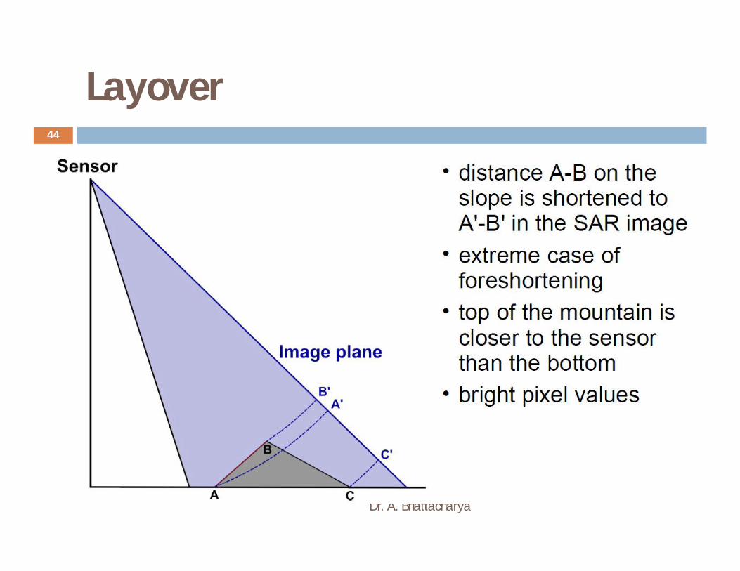
Layover
Dr. A. Bhattacharya
44
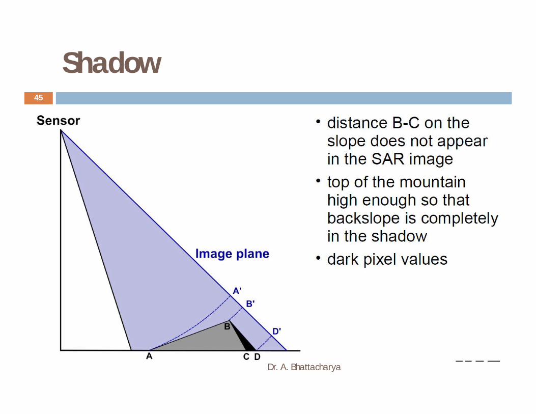
Shadow
Dr. A. Bhattacharya
45
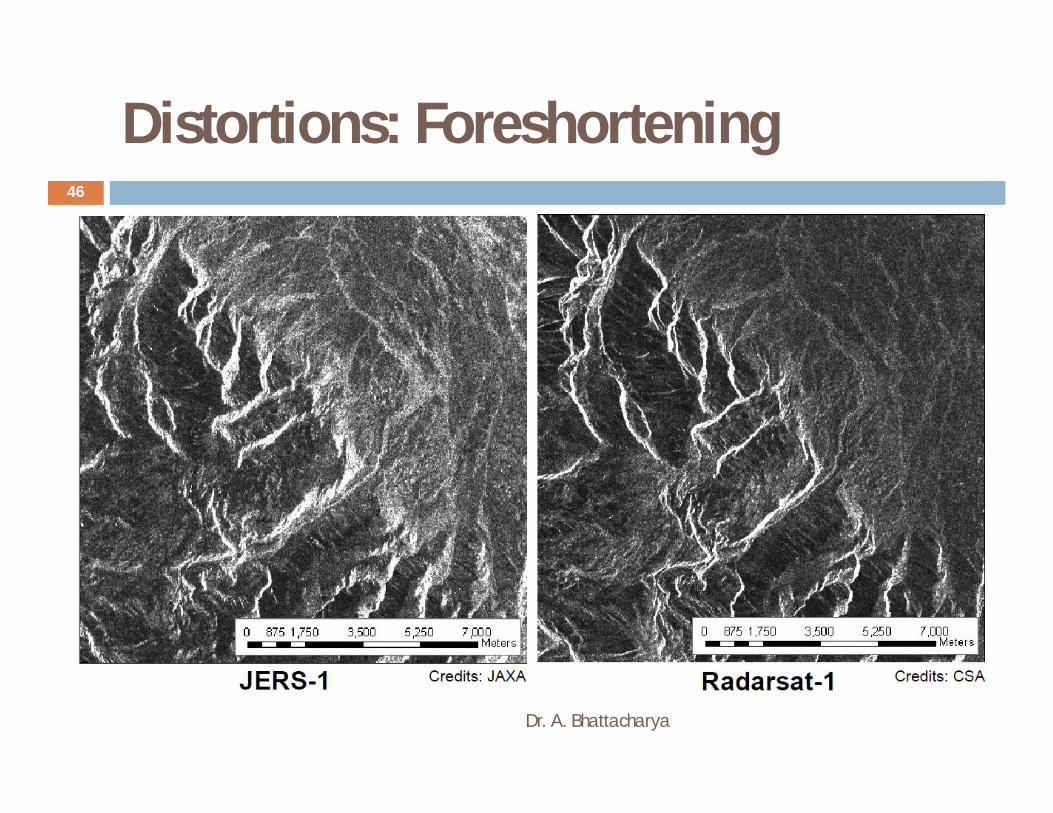
Distortions: Foreshortening
Dr. A. Bhattacharya
46
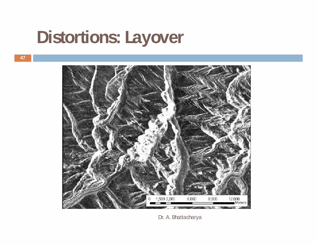
Distortions: Layover
Dr. A. Bhattacharya
47

Distortions: Shadow
Dr. A. Bhattacharya
48

The Radar Equation
Dr. A. Bhattacharya
49
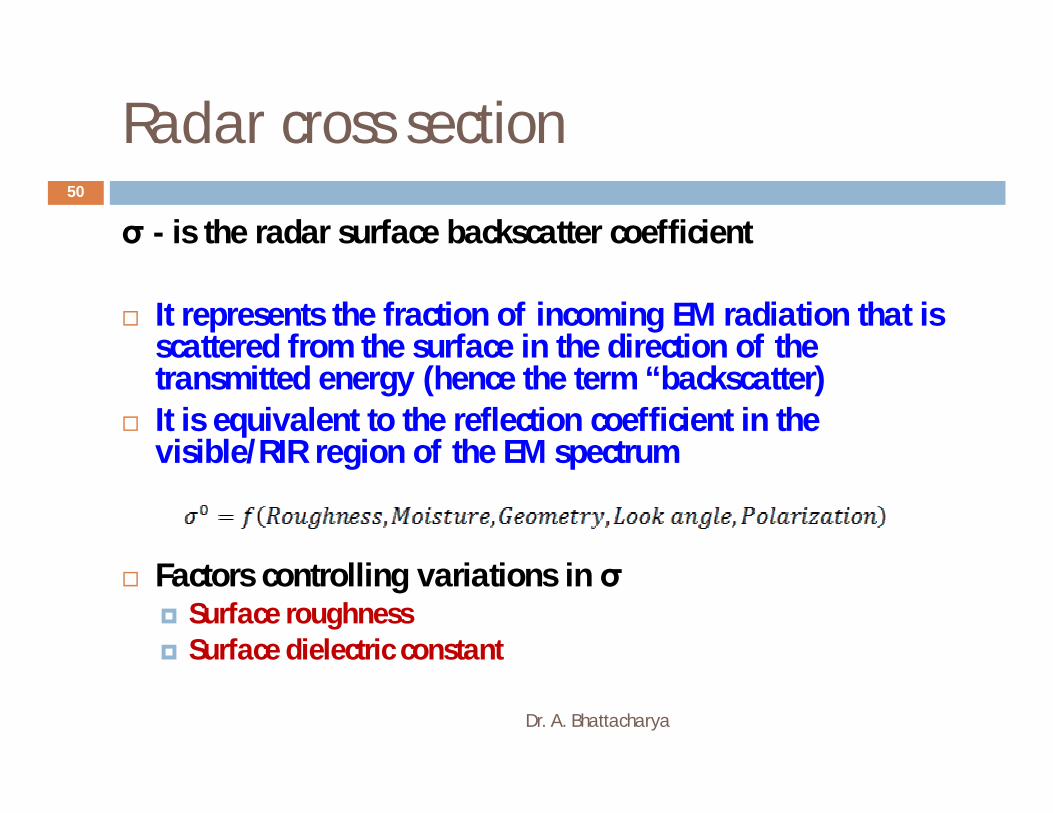
Radar cross section
Dr. A. Bhattacharya
50
σ - is the radar surface backscatter coefficient
It represents the fraction of incoming EM radiation that is scattered from the surface in the direction of the transmitted energy (hence the term “backscatter)
It is equivalent to the reflection coefficient in the visible/RIR region of the EM spectrum
Factors controlling variations in σ Surface roughness Surface dielectric constant
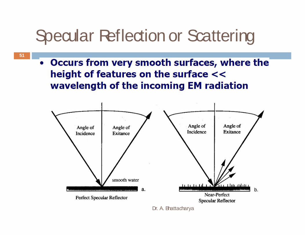
Specular Reflection or Scattering
Dr. A. Bhattacharya
51

Diffuse Reflectors or Scatterers
Dr. A. Bhattacharya
52
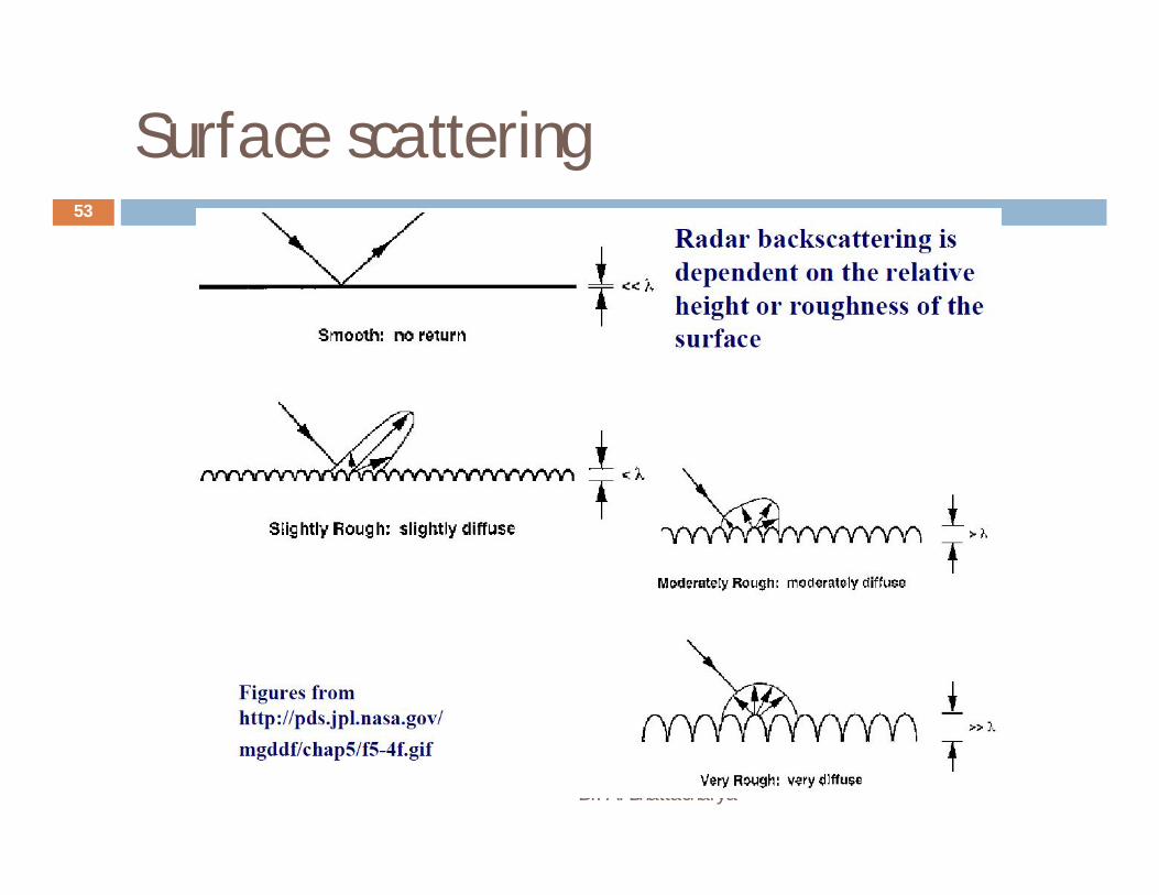
Surface scattering
Dr. A. Bhattacharya
53

Scattering dependency on wavelength
Dr. A. Bhattacharya
54

Radar wavelengths
Dr. A. Bhattacharya
55

Scattering dependency on wavelength
Dr. A. Bhattacharya
56

Scattering dependency on incidence angle
Dr. A. Bhattacharya
57
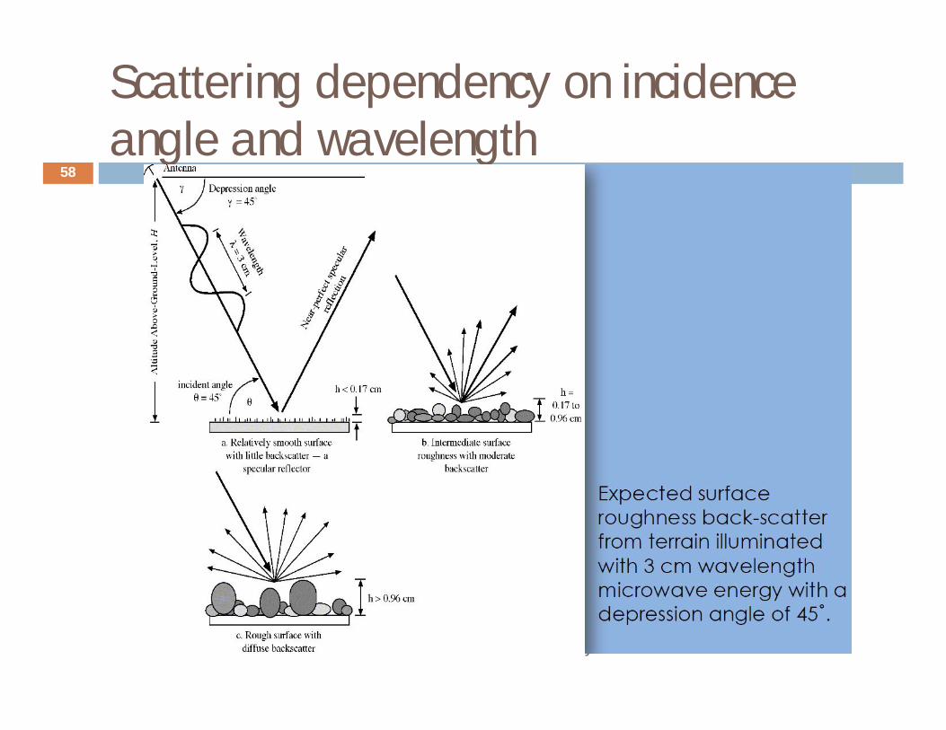
Scattering dependency on incidence angle and wavelength
Dr. A. Bhattacharya
58
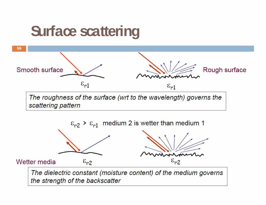
Surface scattering
Dr. A. Bhattacharya
59

Radar image interpretation I
Dr. A. Bhattacharya
60

Radar image interpretation II
Dr. A. Bhattacharya
61

Effect of surface roughness- Internal waves
Dr. A. Bhattacharya
62
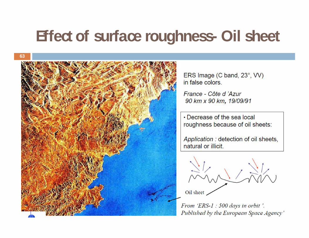
Effect of surface roughness- Oil sheet
Dr. A. Bhattacharya
63
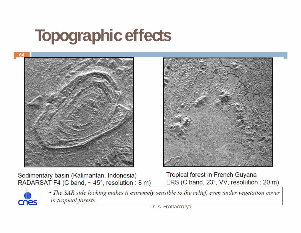
Topographic effects
Dr. A. Bhattacharya
64

Multitemporal analysis
Dr. A. Bhattacharya
65
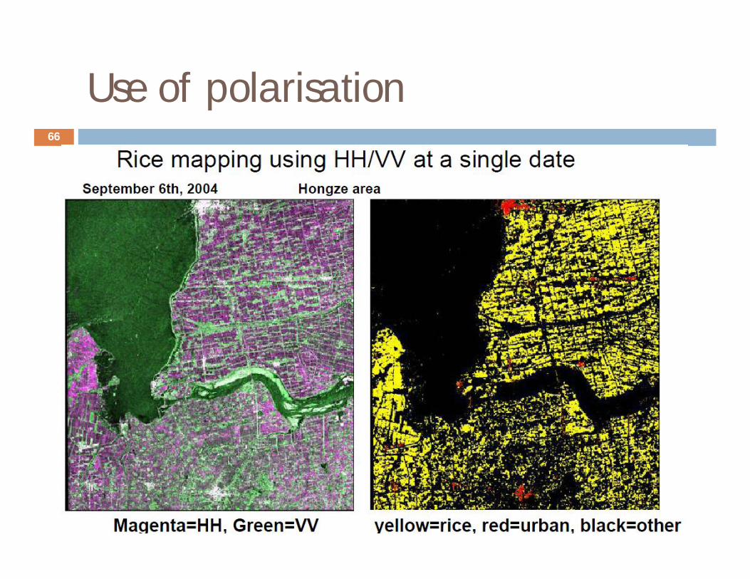
Use of polarisation
Dr. A. Bhattacharya
66

Sub-canopy penetration
Dr. A. Bhattacharya
67
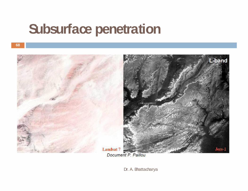
Subsurface penetration
Dr. A. Bhattacharya
68
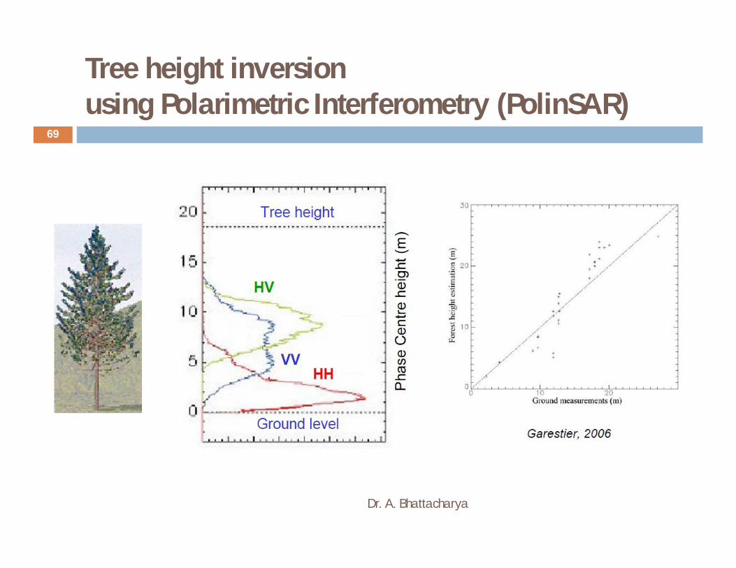
Tree height inversionusing Polarimetric Interferometry (PolinSAR)
Dr. A. Bhattacharya
69
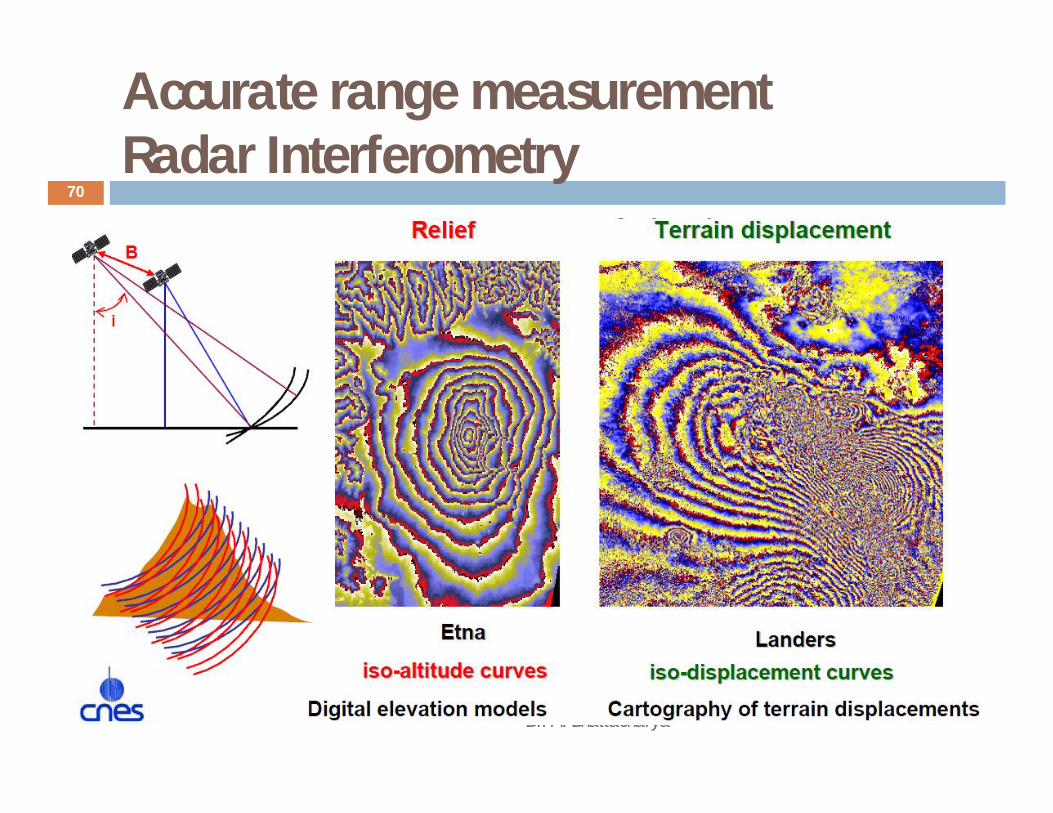
Accurate range measurementRadar Interferometry
Dr. A. Bhattacharya
70