basic thermodynamics prof. s k som department of ... -...
TRANSCRIPT

1
Basic Thermodynamics Prof. S K Som
Department of Mechanical Engineering Indian Institute of Technology, Kharagpur
Lecture - 21 Vapors Power Cycle-II
Good morning to all of you. Today, we will be continuing our discussion on Rankine
cycle, which we started last class. It is an ideal vapor power cycle, where the working
system is water which changes its phase, while passing through the different processes of
the cycle or executing different processes of the cycle. We have also recognized that the
Rankine cycle is an ideal reversible cycle with water as the working system with changes
its phase, executing different processes; this is the theoretical cycle of a steam power
plant. We have also recognized the different components of a steam power plant and
what are their basic operations or intended operations. The power plant has been designed
in such a way that the ideal processes in each and every component should follow the
processes of the Rankine cycle. That means, the cyclic process executed by the working
fluid, water - in steam power plant the working fluid is water - which receives heat in the
boiler; then, it is converted into steam; then, it is expanded in the turbine - we have
already studied this, just the basic purposes of different components. Then the wet steam
at the exhaust of the turbine is condensed in a condenser where circulating water takes
the heat from the steam. Then it is being pumped to the high pressure to the boiler.
Therefore, these different processes should follow the processes of a Rankine cycle; the
cycle in the power plant should follow ideally a Rankine cycle. Therefore, Rankine cycle
is the theoretical cycle of the power plant or other way you can tell the power plant has
been thermodynamically designed, so that its cyclic operation or cyclic process should be
the Rankine cycle. Therefore, now from these, probably we appreciated the
understanding of Rankine cycle.
Now see that if we try to understand the different influence of different operating
parameters on the power plant - what is the goal of an engineer? If there is a power plant,

2
he wants to find the operating conditions at which the power plant will run at the
maximum efficiency. That means, you will get the maximum work at the cost of the
minimum input energy, which is basically the input means the chemical energy of the
fuel. That is being converted into thermal energy, which we call as heat and then that is
being converted into watts. So, to know the influence of the operating conditions - what
should be the operating parameters at which the thermal efficiency of the plant will be
maximum - we must study the theoretical cycles and what are the of influences of the
operating parameters of the theoretical cycle on its efficiency because the qualitative
trend will be same. You understand? Though this theoretical cycle is an ideal cycle, you
can argue: sir in practice this is a concept actually; then in practice, the cycle differs from
the theoretical cycle. Today we will be discussing that, but nevertheless if we analyze the
influence of any operating parameters, for an example, the boiler pressure on the
efficiency of the power plant of the Rankine cycle, the qualitative trend will be same as
that in practice. So it will increase with the increase in pressure, whether that the
efficiency will increase or not this qualitative trend will remain the same. That is why it is
of utmost importance to study the theoretical cycles. So with these I will start again just
recapitulate the Rankine cycle. This is the Rankine cycle.
(Refer Slide Time: 00:04:39 min)

3
This is the Rankine cycle in TS diagram. Let this be the boiler pressure and we consider
let this is be the saturated steam; let this be the condenser pressure and this is the boiler
pressure in the liquid line. So we will appreciate it, but let the [00:05:01] turbine is
superheated. So 1, 2 is the turbine expansion; 2, 3 is the condenser; so in this direction
condensation of the steam occurs. This is the feed pump and 4, 2, 1 is the boiler
If we again recapitulate this boiler: the basic component, then it comes through a turbine;
this is the turbine; from turbine exhaust, where does it go? It goes to a condenser; very
simple, it goes to a condenser. This is turbine T, this is condenser where the circulating
water flows and takes the heat from the steam to condense. There is a feed pump FP. So
this is the process. If we just designate the point 1, 2, then this will be this like this; this is
the inlet to the turbine 1 and this is the point 2. Therefore, this is the point 2 to 3; 3 is the
condenser 3 to 4; so we have discussed this last class.
You see, in practice, there are certain losses which are inevitable, because, of which this
diagram alters slightly in to a different loop.
What is this? First of all turbine, if we consider this turbine, usually this process is
considered to be isentropic, which means the process would be reversible and adiabatic.
There should not be any dissipation; that means, if free from friction, there should not be
any thermal dissipation also. Now to avoid the thermal irreversibility, we can make the
turbine insulated, but sometimes even in proper insulation there is some heat loss from
the turbine. Well, but one thing we cannot, but that we can minimize to a great extent by
properly insulating it, but what we cannot at all minimize is the friction; that means we
cannot ensure that this will be a frictionless flow, frictionless expansion, that is a
reversible expansion. Here we get the work; this also we should write here is Wp; here is
the heat added to the boiler Qb which is the nomenclature in use.
Therefore, this process will not be a reversible adiabatic process. It will be an irreversible
process; to the best, it can be an adiabatic process, but an irreversible process. Therefore,
irreversibility in the turbine has to be taken care of which is the internal irreversibility. If
the process is irreversible, but adiabatic we can consider it then as an approximation that
4
adiabatic but irreversible process; that means, not an isentropic process then the 1, 2 will
not be represented by a vertical line in the TS diagram.
So what will be its nature? What will the type of this curve? Will it incline to the right or
to the left? Right. It will be inclined to the right, so that the actual process which is not
irreversible, that is why I showed it by a dotted line. This 2 dash is the actual process;
usually, we denote the 2 as the actual process; that is the convention - 2. Then, in that
case, we denote here, for example, here now 2 dash is the actual process. Why it inclines
to the right and not to the left? Entropy will increase. Why entropy will increase?
Because of the increase of entropy principle, because, the entropy change of the system in
the turbine equals to the entropy change of the universe. Since we consider the process to
be adiabatic, that means, an irreversible adiabatic process the entropy change has to be
greater than 0, because it is an isolated system where the process is the real process; so
that delta is is greater than 0. Therefore, it will incline to 2 dash.
Similar is the case in the feed pump; if there is an irreversibility in the feed pump, which
is properly insulated, then the process 3, 4 will end like this (Refer Slide Time: 09:07
min). This will be 4 dash; you see 3 to 4 dash. Now, if we write the expression for WT,
considering the turbine as the control volume, then what do we get? This is h1 minus h2
dash; so this is the actual work done, but if we consider the process i to be isentropic that
is the ideal work, then the ideal work done that is WT ideal is h1 minus h2. Now you see
this h2 dash is always more than h2.
If you draw this diagram, HS diagram, that will be clear; I draw it in a small scale (Refer
Slide Time: 09:52 min). The HS diagram, if you draw this thing in HS diagram, that
means, this is the pressure line. So this is the line where this is the condenser pressure. If
you draw this thing; this is the H and S, if you draw this diagram properly, this is the line,
where; so it this is the point; this is 2; this is 2 dash.
So h2 dash is always more than h2. How do you explain this physically? Obviously,
because, of the irreversibility the friction is converted into intermolecular energy. So
intermolecular energy increases the temperature and when the temperature increases, the
enthalpy of the working system will increase. Therefore, the enthalpy is increased which

5
means WT is less than WT ideal; that means, the work produced by the turbine will be less
than that of the ideal value. This - the ratio of this 2 - is defined as isentropic efficiency of
the turbine. Sometimes, we define it as simply etat; t is for turbine. So this becomes equal
to the actual work divided by the ideal work. If we know the isentropic efficiency of the
turbine, then we can find out the actual work; ee find out this ideal work; ideal work we
can know from the tables, because, ideal work corresponds to the process which is
reversible adiabatic isentropic process.
Therefore a parameter eta isentropic which gauges its performance these are the in the
irreversibility; that means - how much irreversible the process is and how much the actual
work deviates from the ideal one - is determined by this eta isentropic. If you know this
thing, we can find out the actual one.
Similarly, in case of compressor what will happen? The actual feed pump - these are the
similar things, thermo machines - we will do when it handles liquid, then it is called
pump; when it handles compressible flow it is compressor. So 3 to 4 is the ideal work,
but actual work is h4; that means, this is the work needed; this is the work needed, but
what is the actual ideal work? Ideal work is ideal work needed is h4 minus h3. In this case,
if you draw this diagram here in the liquid side also you will see this is just the reverse
that means 4 dash and 4. So 4 dash has a higher enthalpy than the enthalpy at 4 which is
like this h4 dash is more than h4.
Therefore, we see the actual pump work; this you know earlier with the from the control
volume, steady flow energy equation, considering the control volume enveloping the feed
pump. In this case, what happens? The feed pump work required is more than that of the
idea; that means, here in case of turbine we had less work because of irreversibility. In
the case of pump, with the same thing, we have to put more work than that required by
the ideal process. In both the cases, we are suffering a loss and this is defined as the
isentropic efficiency of the compressor; isentropic efficiency of the compressor is defined
as the ideal work requirement divided by the actual work requirement. So that it is always
less than 1 defined as 1; that means if we know the isentropic efficiency of the feed pump
we, can find out the actual work requirement which is more than the ideal work
6
requirement. So it is defined in this way, so that both the definitions give the value of
beta less than 1. Under ideal conditions, the isentropic efficiency of turbine and
compressor both become 1.
Now there are other losses which are not that prominent as the losses in compressor,
turbine and feed pump, because, when we consider an isentropic process in feed pump
and turbine this is really a drastic assumption. This too much a theoretical process,
because, no process can be accomplished without friction as the mechanical dissipative
agent; so friction has to be there; it is inevitable.
Therefore, if there is a lot of irreversibility which makes the process irreversible and like
this, but other processes we can maintain as close as possible. For example, here if you
see the boiler, the ideal processes which is envisaged, is a constant pressure heat addition;
that means, from 4 dash, for example, we add heat at constant pressure this is the heat
addition process - that is Qb. In a steady flow process, there are various components in the
boiler through which the steam passes; there are number of tubes, headers, through which
the steam passes and ultimately is converted into water process, converted into steam and
steam is taken up.
So under a steady flow condition, the pressure drop that takes place…. So, usually in a
steady flow condition, I have told that is no pressure drop until and unless friction takes
place. That means, without friction if a fluid flows in a steady flow process, there is no
pressure drop. Therefore, the pressure drop, because, of friction has to be taken care of so
that this process does not become a constant pressure process, but that is not very high if
you consider this value related to the boiler pressure; so that one can neglect it.
However, one can show it in the diagram in this fashion. Apart from that, if you make the
boiler insulated that means we show this Qb added from outside to denote this
thermodynamic ideal cycle. Actually, what is happening? Within the boiler, the fuel is
fed and it is being burned and heat is generated and it is being supplied to the working
system. Therefore the entire boiler, if it is insulated, that means no heat goes out of the
boiler. You understand? This heat is coming outside means this is outside to the working
system water and this heat is actually generated within the boiler itself.

7
Therefore, if you consider the boiler to be ideal as so insulated, then there will be no heat
loss, but in fact, there will be certain heat loss from the boiler. This is shown like this. So
because of this, there is a certain loss in pressure. Also, let this pressure line very much
loss in pressure and certain decaying rather this this is the point actual; one point
decaying temperature; also decrease in temperature.
So this point 1 is a point which is at a lower pressure than the boiler pressure p1 and
which is at a lower temperature than the boiler temperature T1. This is
thermodynamically expressed as two processes; this pressure drop due to friction is
expressed as a throttling process from 1. That means, you draw a throttling process like
this (Refer Slide Time: 16:52 min). So, this is a throttling process 1 to 1 dash and then at
constant pressure cooling to this point 1 double dash. That means, I draw it in a larger
scale, so that you can understand this better. It is not very important, but you must know
that how this is being represented, if we want to represent it.
(Refer Slide Time: 00:17:08 min)
If the boiler pressure drops and heat loss is being represented… let us draw it in an
exaggerated manner. Let this be the point 1 and let forget this is this part. Now it is
assumed that the boiler pressure drop is this; let this is the pressure drop in the boiler and
there is a marginal temperature; this is T1; this is p1. This point comes somewhere here;

8
actually, this is the point 1; the actual point comes here; let 1 double dash. So this 1
double dash point suffers a change in pressure and change in decrease in pressure and
decrease in temperature. This is theoretically represented like this, as if we consider an
isenthalpic process; this is an isenthalpic process; h is equal to constant. Isenthalpic
process which drops the pressure from 1 to let this point is 1 dash and then as if there is a
constant pressure cooling from 1 to 1 double dash.
That means, this point (Refer Slide Time: 18:14 min) which suffers the loss in pressure
and the loss in temperature, decrease in pressure and temperature, is constituted by
constituting two processes: one is isenthalpic process through 1 to the reduced pressure
which is h is equal to constant line, which cuts this point and a constant pressure cooling.
This is this is simulated by these two processes, so that this becomes the any inlet point of
the turbine. That means, outlet to the boiler and accordingly we can determine this
process or the actual processes like this.
These are the typical losses that take place in a power plant, which can modify the
Rankine cycle. I will not tell that in the condenser there is no pressure drop for the
working system, because, it changes its phase and phase change takes place only at the
constant pressure. If it is heavily insulated, that means, only heat that is being taken is
that by the circulating water; no heat is loss to any third body. So, that, we can very well
represent by a constant pressure cooling line.
So these are the places - that is, the turbine expansion, pump compression and the boiler
heating up process at constant pressure, where we can modify according to the losses in
actual power plant processes.
Now, the most important part; we will come to the most important part of this discussion:
how to increase the efficiency of a Rankine cycle.

9
(Refer Slide Time: 00:19:50 min)
Again and again I am telling you from the beginning, I am telling you that why you will
read Rankine cycle - because this is the first thing which comes in our mind: that why
you will unnecessarily read a theoretical cycle? Because theoretical cycle is never
possible; the ideal processes are never possible. Why will you unnecessarily put or if
[(00:20:09)] what is the influence of this parameter, that parameter, pressure, inlet,
temperature, inlet pressure on the efficiency? You understand the efficiency is the output
parameter. Why? This is because, this theoretical cycle, is the cycle of the theoretical
cycle, of which the power plant is designed.
So the actual cycle may differ from the theoretical cycle. Any parameter predicted from
the theoretical cycle under an operating condition, may not quantitatively match with that
of the actual cycle, but the qualitative trend; try to understand. That means the qualitative
influence of any operating parameters on the output parameters will be same for both the
cases. That is the reasons we study this. If a theoretical cycle analysis tells that an
increasing boiler pressure will increase the thermal efficiency of the plant, the actual
cycle will not tell the reverse. You understand? So that we can understand that it has to be
increased, but the quantitative result, that means, the increase of boiler pressure or some
some value if you double it, then increase in efficiency will be something, that may not
match ideally.
10
Therefore, we are now interested to know what is the influence of different operating
conditions on thermal efficiency of the plant, which is the only important parameter for
thermodynamic design. Let us consider a case of an ideal cycle. So this is the cycle. This
is the point 1, point 2, point 3, point 4. Now, we see in this cycle, that heat addition
process is here, where heat is being added. Here it is the heat addition process. This is Qb.
What is heat rejection process? It is Qc.
We know the efficiency of any ideal cycle can be expressed, because ,we can express the
efficiency or in terms of the h1, h2, h3, h4 all values. From Carnot’s theorem, we know the
efficiency of the any reversible cycle is 1 minus temperature of heat rejection which is at
T2 divided by temperature of heat addition. Whenever we define this thing - that is eta is
1 minus temperature of heat rejection by temperature of heat addition, we always imply it
is the mean temperature of heat rejection divided by mean temperature of heat addition.
Usually, the heat rejection temperature, in all practical cases, becomes almost constant.
This is because usually the heat is rejected into the atmosphere where the ambient
temperature is constant. In case of a power plant, it is rejected at a different temperature
lower than the ambient temperature, but the temperature remains constant because it is a
phase changing transfer.
Therefore, the temperature of heat rejection is the temperature of heat rejection it is
constant, but temperature of heat addition is the mean temperature of heat addition which
we have already discussed earlier. Tm1, which is the temperature like this (Refer Slide
Time: 23:33 min). This is the mean temperature of heat rejection. We have discussed this;
this is the mean temperature Tm which makes this rectangle, the area of this rectangle that
is on this x-axis is the same as this one. It gives the same heat transfer and same entropy
change if it is transferred at the mean temperature, which is some mean between 1 to 4.
This is clear. Now from here onwards, we have to think. We know that efficiency
therefore can be expressed like this. To increase the efficiency there are two ways: either
we can decrease this or we can increase this, obviously.
So efficiency thermal efficiency of the reversible cycle can be increased if you decrease
the temperature of heat rejection or if you increase the temperature of heat addition, but

11
temperature of heat rejection cannot go below a certain limit; that I will describe
afterwards. The temperature of of heat rejection is usually fixed by certain type of
characteristic feature or certain constant. Now, we can increase the temperature of heat
addition. We can think over it - how we can increase the temperature of heat addition?
Afterwards I will come why the temperature of heat rejection cannot go below a certain
limit. Similarly, a temperature of heat addition also cannot go beyond the certain limit.
Now you see.
How can you increase the mean temperature of heat addition? One way of obtaining it is
to increase the temperature of the steam to a high degree of superheat, so that as you go
on increasing the maximum temperature T1 along this curve, you will get an increase in
the mean temperature. Mean temperature you will increase if you increase the maximum
temperature to the cycle; you can go on increasing the inlet temperature to the turbine,
but there is a limit for increasing this temperature. This limit comes from where? You
cannot go on infinitely increasing this temperature to a very high value. This limit comes
from the practical consideration of turbine blade materials restriction; that means,
practical consideration or practical restriction imposed by the turbine blade materials
which cannot withstand above a certain temperature; it cannot withstand the temperature
above a certain value. Moreover, this temperature depends upon the working system.
The steam, which is not a very highly superheated gas, it contains moisture, but when it is
superheated moisture also is not there, but because of certain properties of the steam, this
temperature usually it has been found from the metallurgical consideration of turbine
blade should not be made more than 600 to 700 degree Celsius. You cannot go to 1000 or
2000 degree Celsius - the turbine blade material cannot withstand. Therefore, we see
there is a automatically temperature restriction which is 500 to 700 degree; this restriction
is there. I can draw a line, this is my restriction; that is the maximum temperature which I
can go to. Let this be Tmax that is the maximum temperature which is input; maximum
temperature of the cycle. The maximum temperature of the cycle is limited by the turbine
material considerations.

12
Therefore, we see that we cannot go beyond this, but we can even go beyond this
temperature. If this is the temperature, then this is the maximum; this is the mean
temperature of heat addition. The point will be here; the point is 1 dash. So, the mean
temperature of heat addition is increased, which is something between 4 to 1 dash.
If we want to gain more for Tm1 - the mean temperature of heat addition - we can have
another thing; we increase the boiler pressure; we cannot increase the mean temperature
of heat addition more than that which is obtained for point 1 dash and 4. If you go beyond
that the temperature, restrictions will be violated. So, we have temperature more than that
which will be withstood by the turbine blades. Therefore, the average temperature of or
mean temperature of heat addition, if we increase the boiler pressure, if we consider a
boiler pressure like this (Refer Slide Time: 27:53 min) and for the same we make the
point here 4 dash because now 4 dash nomenclature [ ]. If we increase the boiler pressure
so the cycle will change; this will be our 1 double dash. Instead of going 1 dash – earlier I
started with 1, I went to 1 dash at the some existing boiler pressure that is the maximum
temperature limit.
I set the maximum temperature of the cycle to the to the maximum temperature which
can withstood by the turbine blades and at the same time I go on increasing the boiler
pressure, so that the mean temperature at heat addition is increased. Why? This is because
though the maximum temperature is same, the temperature range through which the
water is being heated is now increased, because, this temperature is more than this
temperature. Throughout on this curve the temperatures are more. Here also these
temperatures are more than the saturation temperature at this pressure will be more than
this. (Refer Slide Time: 29:00 min)
For example: this 10 atmospheric pressure and let this be 15 atmospheric pressure.
Obviously, the saturation temperature is more. So the temperature in the cooling water -
the liquid water region - is more. Therefore, the mean of 1 double dash and 4 dash is
more than that of 1 dash and 4; though 1 dash and 1 double dash are same; setting the
same maximum temperature, because, of the metallurgical restriction I can increase the
boiler pressure and I can increase the Tm1, but there now the limit comes for increasing

13
the boiler pressure. So there has to be a gain. Everywhere you see we cannot
monotonically go on increasing an operating parameter to gain the efficiency. So there is
a point where you have to stop. This comes from two ways: one is that efficiency curve
will show that after some increase this will automatically follow; you cannot go; there is
an optimum value you reach - that is number 1. Another one: if you do not have such
optimum value for the efficiency where operating parameter has to be set that beyond
which the efficiency will fall, even if there is a monotonically increasing trend, we get
that natural restrictions imposed on the maximum value which has to be set for this type
of gain. Here now as is you see, that if you increase this boiler pressure, what happens?
For the same temperature if I drop a line here (Refer Slide Time: 30:18 min) this will
meet here, but if I drop a line from here this will meet here. So if I go on still increasing
the boiler pressure, if we consider another boiler pressure, if the same temperature the
line comes here. Now what is changing? You see at the end of the expansions we get that
the dryness fraction is reduced.
If we increase the boiler pressure, that means that the inlet point to the turbine, if the
temperature is kept constant which is set already as the maximum temperature can be
withstood by the turbine blade, but if you go on increasing the boiler pressure to have an
increase in the mean temperature of heat addition; what we sacrifice is the dryness
fraction at the end of the expansion process in the turbine, but why I use the word
sacrifice? This is because if we consider the turbine, so from the boiler, when it comes
here and goes here, then this goes to the condenser and again to the feed pump. Now you
see at the end of the expansion process, the dryness fraction is [ ] drastically reduced.
Now, there is the limit to this minimum value of the dryness fraction; turbine is
composed of several stages: there are rotating blades; there are blades fixed on a rotating
disc which are known as stator elements; they are fixed blades; fixed number fixed blades
which are fixed to the casing of the turbine known as stator blades. So these are the
components of the turbine. So there also the blade material suffers a tremendous loss due
to erosion of the water particles. Amount of water particles increase when the dryness
fraction is decreased that means the quality is decreased; moisture content is increased;
with an increase in moisture content when the steam at high velocity impinges the steam

14
blades or passes or glides along the blade surfaces of the steam turbine, they have an
detrimental effect due to both combined effect of erosion and corrosion for which the
turbine grid life gets deteriorated. The same thing - the material restriction - comes as for
the high temperature beyond certain temperature of 600 or 700 the life of the turbine
blade is drastically reduced. Similar is the case, that if the moisture content at the end of
the expansion in the turbine gets increased over a certain value or the dryness fraction
gets decreased over a minimum value, then the turbine blade material gets drastically
reduced.
Therefore, you see from the viewpoint of the material life of the turbine blades, we have a
restriction on the maximum temperature on the cycle and a minimum dryness fraction at
the end of the expansion; not only at the end, if you follow this line, throughout this
expansion, the dryness fractions are less; throughout the expansion dryness fractions are
less. That means throughout the expansion process, dryness fraction will be above certain
value. So that limitation is imposed on the end process - dryness fraction at the end of the
expansion. Therefore, these two things make or because of these two things, the
maximum temperature and the maximum pressure get fixed.
We know that an increase in Tm1 - the inlet temperature - mean temperature of heat
addition will increase the efficiency, but it cannot go back. Regarding this (Refer Slide
Time: 33:40 min), the minimum temperature I tell you the usual temperature is
sometimes around 40 degree Celsius. What happens? You see that if you go on
decreasing - this question is sometime asked; I will ask you this question in [(00:33:51)] -
that why a condenser is used in a steam power plant? This may be taught in steam power
plant, but this is a very important question in thermodynamics. Why do we use a
condenser in a steam power plant? People who will tell when you [did] the power plant
the very simple answer comes that we know in a power plant the water has to be
condensed and has to be feed back to this pump, which is known as feed pump. So even
if you do not condense this water, so how we can feed this water to the boiler? Through
the feed pump; we require the water to be feedback.

15
Then the question is that: why do you not waste this thing in the atmosphere condensing
and we have a water lake or we have a pond or we have an abundant supply of water
nearby from where we can feed the boiler afresh.
Then the next question comes: when you [did] the power plant you have this will be
inevitable questions which come first in your mind this the practical question - the water
has to be treated properly, because, that water should not contain certain things which is
detrimental to the boiler tube materials, which will be taught afterwards; so treated water
has to be there. Then I give you the answer that a water treatment plant is there, which is
a free gift and whose maintenance is free, so you do not have to bother with this water
treatment. Consider the water is already treated and treated fresh water is abundant in
supply. Even if we will add a condenser at to close the circuit to feed this pump with the
feed water, then the student cannot answer it, because, the answer lies in the
thermodynamic concepts.
Why do you require a condenser? Now you come here, that if we decrease the
temperature of heat rejection, then we get an increase in the efficiency. If you condense it
at atmospheric pressure then this temperature is 100 Celsius; this temperature (Refer
Slide Time: 35:34 min) is fixed by that value, that is the saturation temperature
corresponding to the atmospheric pressure. If you can condense the steam to a pressure
below the atmospheric pressure, you can reduce the temperature of heat rejection; if you
go on subatmospheric pressure condensation still below, lower than the atmospheric
pressure - what you do? The temperature of condensation is also low. For example, if you
go to a pressure of 0.1 atmospheric pressure, roughly, I am not sure point 0.1 or 0.09
atmospheric pressure where the saturation temperature is 40 degree Celsius; you are
capable of making it 40 degrees, whereas if you condense it at atmospheric pressure your
value is 100 degrees; you are gaining an efficiency if you reduce the pressure - that is the
back pressure, this is known as back pressure - the pressure at which the steam should be
condensed to a subatmospheric pressure.
To condense the steam at subatmospheric pressure you will have to design a closed heat
exchanger. You will have to maintain a vacuum there, by arranging some arrangement,

16
by arranging something by which the air can be withdrawn from the condenser by an
vacuum pump, which withdraws the air from the condenser to maintain a certain degree
of vacuum. Therefore, a condenser is required; condenser maintains that and there is a
circulating cooling water which is supplied to the condenser tube which takes the heat
from the condenser. The condenser will… again we taught in power plant, I am not going
into detail of it, there are number of tubes through which the circulating water flows
along the surface of which steam is condensed.
Therefore, the basic purpose of condenser is to reduce the pressure of condensation or to
make the condensation possible below the atmospheric pressure, so that the temperature
of condensation is reduced, so that the temperature of heat rejection is reduced. Then we
get a gain in the thermodynamic efficiency or the thermal efficiency of the plant.
Now a question comes: up to what level you can go? Now the very first question which
comes into the mind of an engineer - probably the minimum level of the pressure will
comes from the restriction of the air in filtration to the condenser; if you go on increasing
the vacuum, more air will ultimately you will not able be able to maintain a vacuum to a
very high degree, but it is not so; even above that a restriction comes - what is that?
Now you know for cooling - this is very important, I am telling you I will ask this
question in an interview, when you may face me - that when the cooling water which is
being circulated within the condenser that is taken from atmosphere; so it has got the
temperature which equals to the ambient temperature; let this temperature be 20 degree
Celsius. So usually, there is a rise in temperature in a condenser in a power plant by 10
degree or like that. Let this comes at 30 degree Celsius. Now we will have to consider the
steel, which is being condensed must be at a temperature little higher than these two
temperatures, little higher than 30 degree Celsius; otherwise it will not flow; the steam
has to condense; you want to condense certain amount of steam. So cooling temperature
has to be low, because, heat transfer is possible only if there is a negative temperature
gradient; heat flows from a high temperature to low temperature.
By chance you create a vacuum whose value is for example 0.05 atmospheric pressure
[(00:38:50)] and you see that the saturation temperature is 20 degree Celsius.

17
So you are very thrilled by seeing this equation efficiency is enhanced by a great amount.
From the circulating water steam is not condensed at all, because, the steam temperature
is lower than the cooling water temperature; the steam may get heated; it may be dried up
also. Therefore, the saturation temperature corresponding to the pressure at which the
steam is condensed must be higher than the available cooling water temperature; very
important. So that saves the limit of the pressure and accordingly the temperature of the
practical cycle.
Here ends my discussion on the influence of the operating conditions like inlet pressure,
inlet temperature, condenser pressure, condenser temperature, on the thermal efficiency,
and how do they behave - in a sense that how the thermal efficiency increases with the
change in this T2 and Tm1.
Now I come to the concept of reheat.
(Refer Slide Time: 00:39:48 min)
Now we have already recognized again and again the same diagram; now we will go on.
We have already recognized that a higher boiler pressure cannot be used. Why? This is
because, we can, for example, here again, I shall show it like this.

18
(Refer Slide Time: 00:40:12 min)
Higher boiler pressure cannot be used. For example, if this is the line, just here I will
show, (Refer Slide Time: 40:23 min) this is the x is equal to 0.85 and usually this is the
value - 85 percent dryness fraction - which is taken as the minimum value at the end of
the expansion. The feet of the expansion should be the cutting point of this x is equal to
0.85 lines and the condenser pressure lines. Now if we increase the pressure, for example,
therefore, this should be the maximum pressure - this p1 – because, if you increase from
this p1 this value get shifted towards the left.
If I am told that 85 percent is the minimum dryness fraction at the end of the expansion
and if this Tmax is your temperature, for example, this is 600 degree Celsius, that means,
the pressure is fixed by this from the geometry. I can draw this line which cuts this
constant temperature; I give this is my isobaric line; that means, this is the pressure, but I
cannot use this high pressure steam, because, you cannot increase the pressure at this
point will come, but I can do so. How? Now, if we start with this point (Refer Slide
Time: 41:29 min) if we increase the boiler pressure, heat the water at higher pressure,
evaporate it or boil it, then again superheat it, and start with this point even, but do not go
throughout from this point (Refer Slide Time: 41:45 min) to the condenser pressure, but
you expand up to some point here, for example.

19
Then you take this steam to a heat exchanger for heating it, which is known as reheating.
Then again, heat the steam at that constant pressure, reduced pressure up to this; that
means, the first expansion takes place; from the initial pressure not to the condenser
pressure to an intermediate pressure; let this is the intermediate pressure. Then heat it
again to the initial temperature. Sometimes it is not heated to the initial temperature, but
you will consider in an ideal case, it is heated to the initial temperature. Then if we drop
it, then we get the same point here. We can maintain the dryness fraction at the end of the
expansion process as from the restriction of the turbine blade. Also, we can use the high
pressure at the boiler, provided we go for a reheat; it is clear provided we go for a reheat.
This is known as reheating; you make the pressure expansion in one turbine up to an
intermediate pressure, then go on heating it and then again expand it.
This is the concept - reheat comes into consideration when we can go for a higher boiler
pressure, but not sacrificing the dryness fraction at the end of the expansion. Now with
this we can straight go to this figure.
(Refer Slide Time: 00:43:17 min)
Here if you see this figure, just let me first draw this, and then it will be understood. This
is the condenser pressure, now this is the boiler pressure - initial boiler pressure.

20
This is the expansion part; this is the point; therefore, this is the maximum temperature
Tmax. Now you see here what happens. 1, 2 then 3; this is 4, this is 5, this is 6. Now you
see what happens. See that this is the restriction; that this is the restriction that is 0.85 line
let x is equal to xmin, that is the minimum value which we can reach, which is usually
0.85 to 0.9.
Here if we could have drawn from this pressure, we have use they very high boiler
pressure, this is the high boiler pressure. This is the temperature. If we could have used p1
this is the p1 pressure and this Tmax temperature and if we could have expanded up to this
condenser pressure - this is the condenser pressure - that is pc, then we could have landed
here (Refer Slide Time: 45:17 min) whose dryness fraction is lower than the xmin; it is not
allowable. Therefore, what is done is that it is expanded to an intermediate pressure; this
is an intermediate pressure line; so this is an intermediate I am drawing a dotted line; this
is the intermediate pressure line p2, up to which it is expanded. This state may come dry
saturated, the state may even come superheated; it may go here, depending upon the
value of the intermediate pressure. Here (Refer Slide Time: 45:47 min) I have shown that
the state has just come; if this is the intermediate pressure after the isentropic expansion,
it cuts the saturated vapor line. It depends upon the operating conditions that will be told
in the problem or in the actual case.
Then again, it is reheated. The cycle is like this: that it expands in the first ejector line,
then it is again reheated, and then it is expanded after we heat to the same maximum
temperature it is being expanded to the condenser pressure. Then the rest part remains the
same. Follow here (Refer Slide Time: 46:15 min) that this is the boiler part; now you see
from the boiler this comes here. I can give this point as 1; so this is 1. After the
expansion, from the HP, this is known as high-pressure turbine, so this expansion takes
place in a turbine known as high-pressure turbine, where this steam extends from the
initial pressure, which is the pressure of the boiler to an intermediate pressure much
higher than the condenser pressure. So this point (Refer Slide Time: 46:44 min)
corresponds to the point 2 high pressure. Then it is again heated and this is a coil-heating
coil which is placed inside the boiler. So it has been shown diagrammatically like that
(Refer Slide Time: 46:57 min). This represents the water drum or steam drum, where heat

21
is being added and steam actually is being evaporated here. This contains both water and
steam and inside the boiler there are places where the fuel is burnt and this burnt gases
exchange heat to the water in evaporating it to the steam or vaporizing it to the steam.
Then, the same burnt gas before going out of the boiler is being used to heat the steam
coming from the high-pressure turbine. It passes through a coil tube and this is known as
reheating. It takes heat from the boiler itself and then after taking this heat, the boiler heat
transfers it; the external heat is now increased. Therefore, because, it heats water to
vaporize and also to heat this steam from the HP turbine to heat it to a temperature of the
state point 3. These are all 3 point and this 3 enters to the LP turbine - low-pressure
turbine.
The low-pressure turbine inlet pressure is this intermediate pressure and this is expanded
to the condenser pressure - 4, and we maintain this dryness fraction. Otherwise, if you
could have used one only HP turbine and could have expanded up to the condenser
pressure, we could have ended up to a dryness fraction which is more than this.
Now here the question comes - well the basic purpose of using the reheat is that we can
go for a high-pressure boiler with the same maximum temperature; I am not sacrificing
this. This is because if this has to be respected - this xminimum - then we will have to use
this pressure. If you have to use this maximum temperature or you will have to use this
pressure if you have to reduce the maximum temperature, but you can use this pressure
and also the maximum temperature, provided you reheat it; that means drop it to an
intermediate pressure and then again reheat to the initial temperature and then drop it to
the condenser pressure.
This is the philosophy of relating that you can use a higher pressure in the boiler or
turbine inlet and go for a expansion ending at to a dryness fraction, which is limited by
the turbine blade material; but, the question is that - whether this reheat increase the
efficiency or not - this question cannot be answered directly. This is because that depends
upon whether the mean temperature of heat addition from 1 to 6 - now mean temperature
of heat addition is changed from - earlier mean temperature of heat addition was
something like 1 to 6 without reheating. Now with reheating the mean temperature of

22
heat addition will be mean for 1 to 6 and also this 3 to 2, the mean of these two mean
temperatures, because, there is also heat addition process at 3 to 2; whether this mean
temperature is increased or not that will determine whether there will be an increase in
efficiency or not. This will depend upon the operating conditions. Now you see what is
that? So this is the heat addition process in the boiler; this is Qb and this is the heat
addition process in the re-heater, which is placed in the boiler itself.
So practically all this heat transfer takes place in the boiler, but now cyclically we are
showing that this is the heat addition process for the water to vaporize to steam and this is
the heat addition for heating this steam from 2 to this state 3. Therefore, we can write
here the heat addition - the Q addition - heat added rather I write, added per unit mass
base if i write, then h1 minus h6 plus h3 minus h2. This is the heat added, whereas heat
rejected which equals to Qc which equals to h4 minus h5.
Therefore, efficiency you can a write as 1 minus heat rejected by heat added. In this case,
the work done in the turbine per unit mass basis can be written as h1 minus h2 - that is the
work done by the high-pressure turbine - plus h3 minus h4 - that is work done in the low-
pressure turbine.
Therefore, if you can draw the cycle diagram vis-à-vis this block diagram you can
designate all the state points accordingly here and there, then you can recognize the
physical processes happening here and corresponding the ideal processes. Then you can
write all these expressions for thermal efficiency and all these things.
Therefore, now the question comes that how can we find out… now for example, now the
problem which may be said like that - if you are told the condenser pressure and this
dryness fraction at the end an expansion, then you can find out what should be t reheat
pressure. If it is reheated to the same initial temperature, if you know the initial
temperature T1, then you can find out first this point T1 and p1.
Then, how to find out the reheat pressure? You can draw a vertical line but TS diagram
you do not have. You can equate this entropy here and entropy here; that means the same

23
temperature here; for example, the inlet temperature is 600 degree Celsius told and the
inlet pressure for example 10 atmosphere p1.
So I fix this point; then at 600 degree Celsius, now I know this entropy. How? Because I
know this dryness fraction limit and I know the condenser pressure; so this point entropy
I know. If we equate this entropy at this temperature in the superheated steam table I will
try to find out at which pressure at this temperature in the superheated steam table these
becomes the entropy. I can find out the pressure; geometrically it is very simple to
understand that if i draw a vertical line up in TS plane this cuts this point. So this is the
intersection point - the isobar - which passes through this is my intermediate pressure. So
this way you can detect the intermediate pressure.
Sometimes it is not wise to do this problems with use of steam table, because, so many
interpolations and the searching out business takes place, because, this entropy this
entropy same. So I will have to find out at this temperature, this entropy, what should be
the pressure? That is why this is done geometrically the way I have explained in TS
diagram, in an HS diagram which is known as Mollier diagram sometime. In the HS
diagram, these problems are solved directly by locating the state points and going like
this. So this HS diagram looks like this.
(Refer slide time: 00:53:38 min)

24
In practice this Mollier diagram, which is available, HS diagram already we have
discussed, but the HS diagram which is available H and S commercially; this looks like
this. This is the line x is equal to 1. You will be having different, line x is equal to 0 .9 x
is equal to 0.8; constant x line like that; x is equal to 0.7 and you will have the constant
pressure divergent line like this. This is the constant. As you know the constant pressure
line are straight lines, but divergent straight lines. These are the constant pressure lines;
there are various constant pressure lines like this.
These are the constant pressure lines: p1, p2, p3, p4, p5, p6, p7; these are the constant
pressure lines. The constant temperature lines in the HS diagram is like this. These are
the constant temperature lines. Why I am doing dotted line? These are the constant T line.
T is equal to constant T is equal to…
So this line bisected only from this; only from this point. Why? In isotherm like this; this
is like this and within the vapor dome constant pressure line is the constant temperature.
For example, if I designate this pressure line as the p is equal to 1 atmospheric pressure; it
meets an isotherm. So this isotherm, will be what this isotherm will be? 100 degree
Celsius. So 100 degree Celsius isotherm is this and coincides with this (Refer Slide Time:
55:28 min). This pressure is the 1 atmospheric pressure. This is typically the diagram;
this is known as Mollier diagram.
Now if we know the condenser pressure, for example, if we know the condenser pressure
and this is my point, this is the condenser pressure pc and my dryness fraction is limited
by point 8. I know the initial temperature and initial pressure here. So how can I find out
the initial temperature is this much? This line and initial pressure is this this is the p5; this
is the initial pressure. This is the initial temperature line. I will get h the initial
temperature line. From this dryness fraction, I will have to go straight, to this point which
will cut this; this p4 will be then my intermediate pressure. I can draw the cycle now like
this. I can draw the cycle on HS plane like this; this will be then made like this. If I can
draw this, I can read all the points; this is the same temperature; I can read this point, I
can ready this point, I can ready this point. Directly we can get enthalpy. We can
construct the process on the HS diagram.

25
So it is very easy to find out the reheat pressure in HS diagram that i draw the isentropic
lines straight, it cuts the same temperature line. Let this is equal to 600 degree Celsius; let
p5 be 10 atmospheric pressure. So this is my inlet point 1.
This is the constant pressure lines. Now if it is turned, that it is expanded up to the
disaturated condition, which is usually made in practice, then my 1, 2 point is there. This
is my 3 point; then this is my 4 point. So 1, 2, 3, 4 process. That is the expansion in the
high-pressure turbine reheat and the expansion in the low-pressure turbine I can do it
here.
Directly I can find out h1, h2, h3, h4. You can read it and you can get the value. It is more
wise to use this diagram then the string table, but a request is that before the examination
you must have a practice with this diagram, so that day of the examination if get to solve
with this, then you may find difficultly. So that you will have to see how does it look? It
looks like this. You have to solve one or two problems using this diagram where you can
straight away locate the state points. This is about reheat.
Tomorrow I will solve a problem on reheat and we will start another new thing - concept
of regeneration.
Thank you.

26
(Refer Slide Time: 00:58:13 min)
(Refer Slide Time: 00:58:25 min)

27
(Refer Slide Time: 00:58:38 min)
(Refer Slide Time: 00:58:53 min)
28
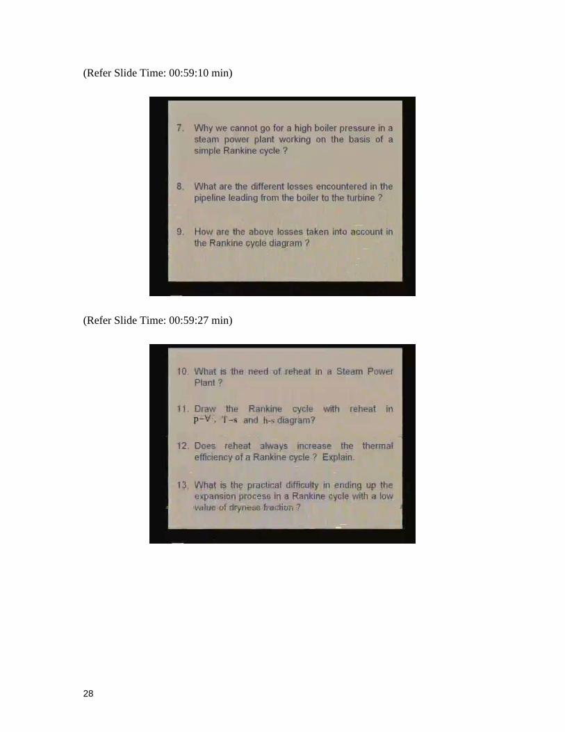
(Refer Slide Time: 00:59:10 min)
(Refer Slide Time: 00:59:27 min)

29
(Refer Slide Time: 00:59:41 min)