basic template for the development of iso and...
TRANSCRIPT

© ISO 2013 – All rights reserved
Reference number of working document: ISO/IEC JTC 1/SC 24 N 000Date: 2014-08-18
Reference number of document: ISO/IEC WD 18521-3 (ver. 3.0)
Committee identification: ISO/IEC JTC 1/SC 24/WG 9
Secretariat: Charles A. Whitlock
Information technology — Computer graphics, image processing and environmental representation —
Live Actor and Entity Representation in Mixed and Augmented Reality
Warning
This document is not an ISO International Standard. It is distributed for review and comment. It is subject to change without notice and may not be referred to as an International Standard.
Recipients of this draft are invited to submit, with their comments, notification of any relevant patent rights of which they are aware and to provide supporting documentation.
Document type: International StandardDocument subtype: subtypeDocument stage: (20) CommitteeDocument language: E
STD Version 1

WORKING DRAFT ISO/WD nnn-n
Copyright notice
This ISO document is a working draft or committee draft and is copyright-protected by ISO. While the reproduction of working drafts or committee drafts in any form for use by participants in the ISO standards development process is permitted without prior permission from ISO, neither this document nor any extract from it may be reproduced, stored or transmitted in any form for any other purpose without prior written permission from ISO.
Requests for permission to reproduce this document for the purpose of selling it should be addressed as shown below or to ISO’s member body in the country of the requester:
[Indicate :the full addresstelephone numberfax numbertelex numberand electronic mail address
as appropriate, of the Copyright Manager of the ISO member body responsible for the secretariat of the TC or SC within the framework of which the draft has been prepared]
Reproduction for sales purposes may be subject to royalty payments or a licensing agreement.
Violators may be prosecuted.
© ISO 2012 – All rights reserved 1

WORKING DRAFT ISO/WD nnn-n
Contents Page
Foreword............................................................................................................................................................ Introduction.........................................................................................................................................................1 Scope..................................................................................................................................................... .2 Normative References......................................................................................................................... ..3 Terms, Definitions and Symbols........................................................................................................ ..4 Concepts............................................................................................................................................... ..4.1 Overview............................................................................................................................................... ..4.2 Components......................................................................................................................................... ..5 Sensors for live actors and entities................................................................................................... ..5.1 Overview............................................................................................................................................... ..5.2 Computational and information view................................................................................................. ..6 Recognizer and Tracker...................................................................................................................... ..6.1 Overview............................................................................................................................................... ..6.2 Computational and information view................................................................................................. ..6.3 Events recognition............................................................................................................................... ..7 Spatial Mapper..................................................................................................................................... ..7.1 Overview............................................................................................................................................... ..7.2 Computational and information view................................................................................................. ..8 Event Mapper....................................................................................................................................... ..8.1 Overview............................................................................................................................................... ..8.2 Computational and information view................................................................................................. ..8.3 Event execution9 Renderer and Simulator10 Display and UI...................................................................................................................................... ..11 Conformance
ANNEX A. Use cases........................................................................................................................................ ..A.1 3D virtual studioA.2 3D virtual car controller A.3 3D virtual book storeA.4 3D virtual object augmentationA.5 3D virtual teleconference
© ISO 2012 – All rights reserved 2

Bibliography
© ISO 2012 – All rights reserved 3

Foreword
ISO (the International Organization for Standardization) and IEC (the International Electrotechnical Commission) form a specialized system for worldwide standardization. National bodies that are members of ISO or IEC participate in the development of International Standards through technical committees established by the respective organization to deal with particular fields of technical activity. ISO and IEC technical committees collaborate in fields of mutual interest. Other international organizations, governmental and non-governmental, in liaison with ISO and IEC, also take part in the work. See http://www.iso.org for information on ISO and http://www.iec.ch for information on IEC.
In the field of information technology, ISO and IEC have established a joint technical committee, ISO/IEC JTC 1. Draft International Standards adopted by the joint technical committee are circulated to national bodies for voting. Publication as an International Standard requires approval by at least 75% of the national bodies casting a vote. See http://www.iso.org/ for information on JTC 1.
This draft was prepared by Joint Technical Committee ISO/IEC JTC 1, Information technology, Subcommittee 24, Computer graphics, image processing and environmental data representation.
ISO/IEC 1 consists of the following parts, under the general title Information technology — Computer graphics, image processing and environmental data representation:
Mixed and Augmented Reality Concepts and Reference Model: Part 3 – Live actor and entity Representation
4 © ISO 2012 – All rights reserved

Introduction
This working draft defines a representation model for live actor and entity to be included in a mixed and augmented reality (MAR) world. It defines representing and rendering for live actor and entity in a mixed and augmented reality world and interaction interfaces between the live actor/entity and objects in a MAR world. It defines a set of principles, concepts, and functionalities for live actor and entity applicable to the complete range of current and future mixed augmented reality standards. It includes (but is not limited to) the following content:
- Requirements and scope
- Terms and definition for live actor and entity in a MAR world
- A representation model of live actor and entity that can be included in a MAR world
- 3D modelling, rendering, and simulation of live actor and entity in a MAR world
- Attributes of live actor and entity in a MAR world
- Sensing Representation of live actor and entity in a MAR world
- Representation of the interfaces for controlling live actor and entity in a MAR world
- Functionalities and base components for controlling live actor and entity in a MAR world
- Interactive Interfaces between live actor/entity and a MAR world
- Interface with other MAR components
- Relationship to other standards
- Use cases
The objectives of this work are as follows:
- Provide a reference model for live actor and entity representation based MAR applications
- Manage and control live actor and entity with their properties in MAR environments
- Integration of live actor and entity into a 3D virtual scene in MAR worlds
- Interaction of live actor and entity and a 3D virtual scene in MAR worlds
- Provide an exchange format necessary for transferring and storing data between live actor and entity based MAR applications
© ISO 2012 – All rights reserved 5

Information technology — Computer graphics, image processing and environmental representation — Live Actor and Entity Representation in Mixed and Augmented Reality (MAR)
1 Scope
This International Standard, Mixed and Augmented Reality Concepts and Reference Model – live actor and entity(LAE) Representation, defines a reference model and base components for representing and controlling live actor and entity in mixed and augmented reality (MAR) worlds. It defines concepts, a reference model, system framework, functions, and how to integrate 3D virtual worlds and live actor and entity and their interfaces in order to provide MAR applications with live actor and entity interfaces. It defines an exchange format necessary for transferring and storing live actor and entity related data between MAR applications based on live actor and entity.
This International Standard specifies the following functionalities:
a) Definition of live actor and entity
b) Representation of live actor and entity
c) Representation of properties of live actor and entity
d) Sensing of live actor and entity in a real world
e) Integration of live actor and entity into a 3D virtual scene
f) Interaction between live actor/entity and objects in a 3D virtual scene
g) Transmission of information among live actors/entities in MAR worlds
This International Standard defines a reference model for live actor and entity based MAR applications to represent and to exchange data related to live actor and entity in a 3D virtual scene in MAR worlds. It does not define specific physical interfaces necessary for manipulating live actor and entity, that is, does not define how specific applications shall implement with specific live actor and entity in MAR world, but instead defines common functional interfaces for representing live actor and entity that can be used interchangeably between the MAR applications.
6 © ISO 2012 – All rights reserved

2 Normative references
The following referenced documents are indispensable to the application of this document. For dated references, only the edition cited applies. For undated references, the latest edition of the referenced document (including any amendments) applies.
ISO/IEC 11072:1992, Information technology -- Computer graphics -- Computer Graphics Reference Model
ISO/IEC 19775-1.2:2008, Information technology — Computer graphics and image processing — Extensible 3D (X3D)
ISO/IEC 14772:1997, Information technology -- Computer graphics and image processing -- The Virtual Reality Modelling Language (VRML) -- Part 1: Functional specification and UTF-8 encoding
ISO/IEC CD 18039, Information technology -- Computer graphics and image processing – Mixed and Augmented Reality Reference Model, August, 2015
ISO/IEC 200x, Information technology -- Computer graphics and image processing – Physical Sensor Representation in mixed and augmented reality, August, 2015
© ISO 2012 – All rights reserved 7

3 Terms, Definitions, and Symbols
This standard basically uses a set of terms and definitions, and symbols defined in given in ISO/IEC CD 18039, Information technology -- Computer graphics and image processing – Mixed and Augmented Reality Reference Model, and additionally, the following apply.
3.1 Terms and Definitions
Physical scene
An image or video which be captured from “real world capturer” in a real world
Physical data
Data which be captured from “real world capturer” or “pure sensor” in a real world
Physical data
Data which be captured from “real world capturer” or “pure sensor” in a real world
Static object
An object which cannot be translated, rotated and scaled in a real world or a virtual world
Dynamic object
An object which can be translated, rotated and scaled in a real world or a virtual world
Augmented object
An object with Augmentation
Live actor and entity
A representation of a living physical/real user/actor in the MAR content or system
Motion Volume
A volume where a live actor and entity can be movable in a real world or in a virtual world
3.2 Symbols (and abbreviated terms)
LAE Live Actor and Entity
LAE-RM-MAR
Live Actor and Entity representation in Mixed and Augmented Reality Reference Model
RWMV_LAE
Motion Volume of Live Actor and Entity in a Real World
VWMV_LAE
Motion Volume of Live Actor and Entity in a Virtual World
S-Camera Stereo Camera
D-Camera Depth Camera
8 © ISO 2012 – All rights reserved

RGB Red Green Blue
SID Sensor identifier
4. Concepts
4.1 Overview
As illustrated in ISO/CD 18039: Mixed and Augmented Reality Reference Model, Mixed and Augmented Reality (MAR) represents a continuum that encompasses all domains or systems that use a combination of reality (e.g. live video) and virtuality representations (e.g. computer graphic objects or scene) as its main presentation medium. MAR is defined according to the relative mixture of the reality and virtuality representations. The MAR ranges between “All Physical, No Virtual” and “All Virtual, No Physical” as shown in Figure 1.
Figure 1. Mixed and Augmented Reality (MAR)
This clause describes the concepts of a live actor and entity representation in MAR world based on an MAR reference model(MAR-RM) of ISO/CD 18039, which include definitions, objectives, scopes, embedding, interaction, and functions of the system for representing a live actor and entity. The live actor and entity in this standard is defined as a representation of a physical living actor and object in the MAR content or system.
An MAR world consists of a 3D virtual world and directly sensed and computer-generated information including any combination of aural, visual, touch, smell and taste. For a simple example, the conceptual scene of the MAR world is represented as shown in Figure 2. The figure displays an MAR world constructed by integrating a 3D virtual world and live actors, captured from a general camera and/or depth camera sensors. In this figure, the 3D virtual world describes a real-like educational space in a library, whose roles are learners as well as teachers, participate in the 3D virtual educational world and how is their participation represented in the world. To provide the educational effectiveness of the immersive and interactive learning systems to the learners, we adopt that live actor and entity in the real space can be embedded into the 3D virtual learning space. The MAR education service, that is, an augmented virtuality service, has the strong point of providing intensive immersion and interaction to both teachers and learners. The service can be applicable to provide an integrative combination application of 3D videoconferencing, reality-like communication features, presentation/application sharing, and 3D model display within mixed environment.
© ISO 2012 – All rights reserved 9

Figure 2. An example of live actor and entity representation in an MAR world
Once live actor and entity in the real world are integrated into a 3D virtual world, their location, movements and interactions should be represented precisely in the 3D virtual world. In the MAR applications, live actor and entity to be embedded in a 3D virtual world must be defined, and their information such as location, actions, and sensing data from their holding equipment, must be able to be transferred between the MAR applications, and between a 3D virtual world and a real world. This work is intended to define how to exchange the MAR application data in heterogeneous computing environments, and how live actor and entity can be managed and controlled with their properties in a 3D virtual world, and how they can be embedded in a 3D virtual world, and they can interact with virtual cameras, virtual objects, and AR content in the 3D virtual world.
4.2 Components
Based on the MAR-RM proposed in ISO/IEC 18039, the MAR reference model for representing a live actor and entity into the MAR-RM, which is called MARRC-RM, is concretely proposed as shown in Figure 4. Live actor and entity in the MARRC-RM can be captured from physical world, and can be represented in a 3D virtual world, and can interact with cameras, objects and AR content in the 3D virtual world according to their input sensing information for their interaction.
In order to provide a 3D virtual world with the capability of representing live actor and entity based on the MAR-RM, an MAR system requires the following functions:
▪ Sensing of real actor and entity in a real world from input devices such as (depth) camera.
▪ Sensing of information for interaction from input sensors.
▪ Recognizing and tracking of live actor and entity in a real world
▪ Recognizing and tracking of events made by real actor and entity in a real world
▪ Recognizing and tracking of events captured by sensors themselves in a real world
▪ Representation of physical properties of live actor and entity in a 3D virtual world
▪ Spatial Control of live actor and entity into a 3D virtual world
▪ Event Interface between live actor/entity and a 3D virtual world
▪ Composite Rendering of live actor/entity into a 3D virtual world
10 © ISO 2012 – All rights reserved

Conceptually, the system for implementing an MAR world with live actor and entity includes five components necessary for processing the representation and interactions of live actor and entity to be integrated into a 3D virtual world. The configuration of the MAR-RCRM system is shown in Figure 5.
Figure 5. The system Framework for an MAR world with live actor and entity
4.2.1 Sensors
An MAR world with live actor and entity can receive a captured image, a sequence of captured images and sensing data triggered by live actor and entity in the real world. The data for the live actor and entity representation can be obtained from sensing devices/interfaces, and will be classified into two kinds for pure live actor and entity as well as for sensing data for their actions. The data for pure live actor and entity will be used to perform both spatial mapping and event mapping of live actor and entity into a 3D virtual space, and the sensing data will be used to perform event mapping between live actor and entity and a 3D virtual environment.
The MAR-RCRM system can use the devices such as Web cameras and KINECT-like devices. In the case of Web cameras, the sequence of images will be captured and the image itself will be used as an input. Microsoft KINECT is a movement sensing interface device for the movement of live actor and entity. The device consists of an RGB camera, 3D depth sensors, multi-array microphones, and a motorized tilt. The device has used IR(infrared radiation) camera and IR laser projector to take 3D depth information.
4.2.2 Recognizer/Tracker
The modules are required to preprocess the captured image, a sequence of captured images, and the sensing data obtained from the sensing devices and interfaces. The preprocessing examples are chromakeying, color conversion, and background removal. The tracking of live actor and entity is to find the location of them on each image of the sequence. The recognition is to find and to identify actions of live actor and entity in the captured image, a sequence of captured images, and the sensing data.
© ISO 2012 – All rights reserved 11

The modules can be implemented by OpenCV(Open Source Computer Vision Library) which is a library of programming functions mainly aimed at real-time computer vision and developed by Intel.
4.2.3 Spatial Mapper
Live actor and entity in a real world will be embedded into a 3D virtual world in an MAR application. Spatial mapper has a role by which live actor and entity can move more naturally within a 3D virtual world.
4.2.4 Event Mapper
Live actor and entity in a real world will act with their aim. Their actions can be reflected in the 3D virtual world where live actor and entity are participating and interacting with virtual cameras, virtual objects and AR content in the 3D virtual world. This module has the role for actions of live actor and entity.
4.2.5 Renderer/Simulator
The results of spatial and event mappers for live actor and entity are transferred into the rendering module. The module integrates all the results and a 3D virtual scene, and displays the final rendering result of the integrated outcomes.
4.2.6 Display/UI
The final rendering result of the integrated outcomes of LAEs and a MAR world can be appeared on a variety of display devices such as monitors, head-mounted displays, projectors, scent diffusers, haptic devices and sound speakers. User interface provide users to achieve their purpose of modifying the state of the MAR scene.
4.2.7 MAR scene
The MAR scene describes all information which is related to live actors and entities in a MAR environment. The information consists of sensing data, spatial scene, events, targets and others,
12 © ISO 2012 – All rights reserved

5. Sensors for Capturing Live Actors and Entities
5.1 Overview
Live actors and entities in real world can be captured from a hardware and (optionally) software sensor which are able to measure any kind of physical property. As mentioned in ISO/IEC CD 18039, two types, “real world capturer” and “pure sensor” of sensors are used to embed the live actors and entities into a virtual world, and to perform an interaction between them and objects in the virtual world. The most “real world capturer” sensors are video and/or depth cameras which capture a real world as a (depth) video containing live actors and entities. The video will be used to extract the live actors/entities and their actions to be processed in recognizer and tracker component. Specially, the actions may affect interaction between the live actors/entities in a real world and objects in a virtual world. The target physical object can generate physical or nonphysical data which can be captured from “pure sensor”. The (non) physical data can be used to detect, recognize and track the target physical object to be augmented, and to process the interaction. The sensing data will be inputted into recognizer/tracker component.
5.2 Computational and informational view
The sensors receive inputs of a variety of signals to be addressed in real world and obtain sensing data related to representation of live actor and entity in a MAR world.
The input and output of sensors related to live actor and entity in a MAR world are:
Input: Real world signals
Output: Sensor data related to representation of live actor and entity
The physical sensor devices have a set of capabilities and parameters. According to their properties, the sensor devices generate wide sensing data of intrinsic parameters (e.g., focal length, field of view, gain, frequency range, etc.), extrinsic parameters (e.g., position and orientation), resolution, sampling rate, mono, stereo or spatial audio, and 2D, 3D (colour and depth) or multi-view video. To provide the sensing data universally, the sensor output consists of <Identifier> <Type> and <Attributes>.
Table 1. Sensor attributes for live actor and entity
Dimension Types
Real world capturer Pure Sensor
© ISO 2012 – All rights reserved 13

Modality/type of the sensed/captured data
Visual Auditory Electro-magnetic waves (e.g., GPS)
Haptic/tactile
Other physical properties
Type Image/video audio values values Values
The sensed/captured data
(depth) image and video
Audio Latitude,longitude,height
Moving directions
Force, etc
Physical sensing devices
WebCam
RGB camera
Depth camera(KINECT)
Microphones
GPS sensor
Gyro sensor
Haptic/tactile device
To composite a 3D virtual space and live actor and entity, live actor and entity sensing devices to be used should be investigated. The standard can use the following sensing devices: general camera such as Web cameras, and depth camera such as KINECT-like devices. In the case of general cameras, the sequence of RGB images will be captured and the image itself will be used as the sensing data. Depth cameras such as Microsoft KINECT provide the following: an RGB color image, a 3D depth image, multi-array microphones, and a motorized tilt. The captured image and/or the depth image can be used to embed live actor and entity into a 3D virtual space.
6. Recognizer/Tracker of Live Actors and Entities
6.1 Overview
The sensing data may be pre-processed to give better sensing data for doing spatial mapping and event mapping of live actor and entity into a MAR world. The pre-processing functions can be composed of filtering, color conversion, and background removal, chromakeying, and depth information extraction for captured data by using techniques in area of computer vision. The pre-processing work is applied to provide good information for representing live actor and entity.
14 © ISO 2012 – All rights reserved

The pre-processed data will be delivered into two components, those are, recognizer and tracker. The recognizer is used to recognize live actors and/or entities and their events in pre-processed sensing data. And tracker is to recognize consecutive spatial and event data for live actors and/or entities. Work of two components can be done by using information stored into MAR scene.
6.2 Computational and informational view
The Recognizer is a hardware/software component that analyses sensing data related to representation of live actor and entity in a MAR world and produces MAR events and data activated from live actor and entity through comparing with a local or remote target signal (i.e., target for augmentation) stored in MAR scene.
Recognition can only be based on prior captured target signals. Both the Recognizer and Tracker can be configured with a set of target signals provided by or stored in an outside resource (e.g. third party DB server) in a consistent manner with the scene definition, or by the MAR Scene Description (See Section 5.5.6, SEDRIS T014) itself.
Recognizer and Tracker can be independently implemented and used.
The input and output of the Recognizer are:
Input: Sensing data related to representation of live actor and entity in a MAR world
Output: At least one event acknowledging the recognition.
Table 2. Recognizer categories
Dimension Types
1. Form of target signal
2D chromakeying image
3D primitives (points, lines, faces, polygons, skeleton) of live actor and entity
Audio Gesture Others
2. Form of the output event
Event Indication only of the
Event Indication only of the
Event Indication only of the
Event Indication only of the
—
© ISO 2012 – All rights reserved 15

recognized object recognized object recognized object recognized object
. The Tracker is able to detect and measure changes of the properties of sensing data related to representation of live actor and entity in a MAR world.
The input and output of the Tracker are:
Input: sensing data related to representation of live actor and entity.
Output: Instantaneous values of the characteristics of the recognized live actor and entity.
Table 3. Tracker categories
Dimension Types
1. Form of target signal
2D chromakeying image
3D primitives (points, lines, faces, polygons, skeleton) of live actor and entity
3D Model Location(e.g., earth- reference coordinates)
Other
2. Form of the output event
Spatial (2D, 3D, 6D, …)
Spatial (2D, 3D, 6D, …) Spatial (2D, 3D, 6D, …)
Others —
6.3 Event Representation
The events of live actor and entity can be appeared by their actions themselves as well as outputs obtained from sensing interface devices that they have. Live actor and entity will be captured from general cameras and/or depth cameras. Their actions can be obtained by doing recognition of live actor and entity sensing data. Their meaningful events to be used in an MAR world can be classified into two types: sensing data by live actor and entity themselves or sensing data of devices held by live actor and entity. The defined events will be stored into an event database(Event DB).
Sensing outputs captured from “real world capturer” Gestures – hands, fingers, head, body Facial expressions Speech & Voice
Sensing outputs captured from “pure sensor” AR marker GPS(global positioning system) Remote Wii motion data Other sensing data by a smart device: the three-axis accelerometer, the magnetometer (digital compass)
The sensing data will be used to define events of a live actor and entity. We assume that a virtual camera, a virtual object, an AR object in a 3D virtual space are controlled by human body gestures of a live actor and entity. To define the gestures more efficiently, first of all, basic primitive postures of a human body are defined as shown in Figure 10 (a). The postures consist of position, vector, image, skeleton. By detecting the postures of a human body and combining them, gestures for a specific object in the human body can be defined. Among the gestures, we define three common primitive gestures of a human body, those are, linear, wave, clockwise/counterclockwise ones. A variety of events for a human body can be defined as shown in Figure 10 (b) by using pre-defined primitive gestures.
7. Spatial mapper of live actors and entities
7.1 Overview
The role of the Spatial mapper for live actor and entity is to provide spatial relationship information (position, orientation, scale and unit) between the physical space and the space of the MAR scene by applying the necessary transformations for the calibration of live actor and entity.
16 © ISO 2012 – All rights reserved

7.2 Computational and Information view
The spatial reference frames and spatial metrics used in a given sensor needs to be mapped into that of the MAR scene so that the sensed live actor and entity can be correctly placed, oriented and sized. The spatial relationship between a particular sensor system and an MAR space is provided by the MAR experience creator and is maintained by the Spatial Mapper.
The input and output of the Spatial Mapper are:
Input: Sensor identifier (SID) and sensed spatial information of live actor and entity.
Output: Calibrated spatial information of live actor and entity for the given MAR scene.
The notion of the Spatial Mapper can be extended to mapping other domains such as audio (e.g., direction, amplitude, units, scale) and haptics (e.g., direction, magnitudes, units and scale).
8. Events mapper of Live Actors and Entities
8.1 Overview
The Event Mapper creates an association between a MAR event of live actor and entity, obtained from the Recognizer or the Tracker, and the condition specified by the MAR Content Creator in the MAR scene.
It is possible that the descriptions of the MAR events produced by the Recognizer or the Tracker are not the same as those used by the Content Creators even though they are semantically equivalent. For example, a recognition of a particular location (e.g., longitude of -118,24 and latitude of 34.05) might be identified as “MAR_location_event_1” while the Content Creator might refer to it in a different vocabulary or syntax, e.g., as “Los Angeles, CA, USA.”
© ISO 2012 – All rights reserved 17
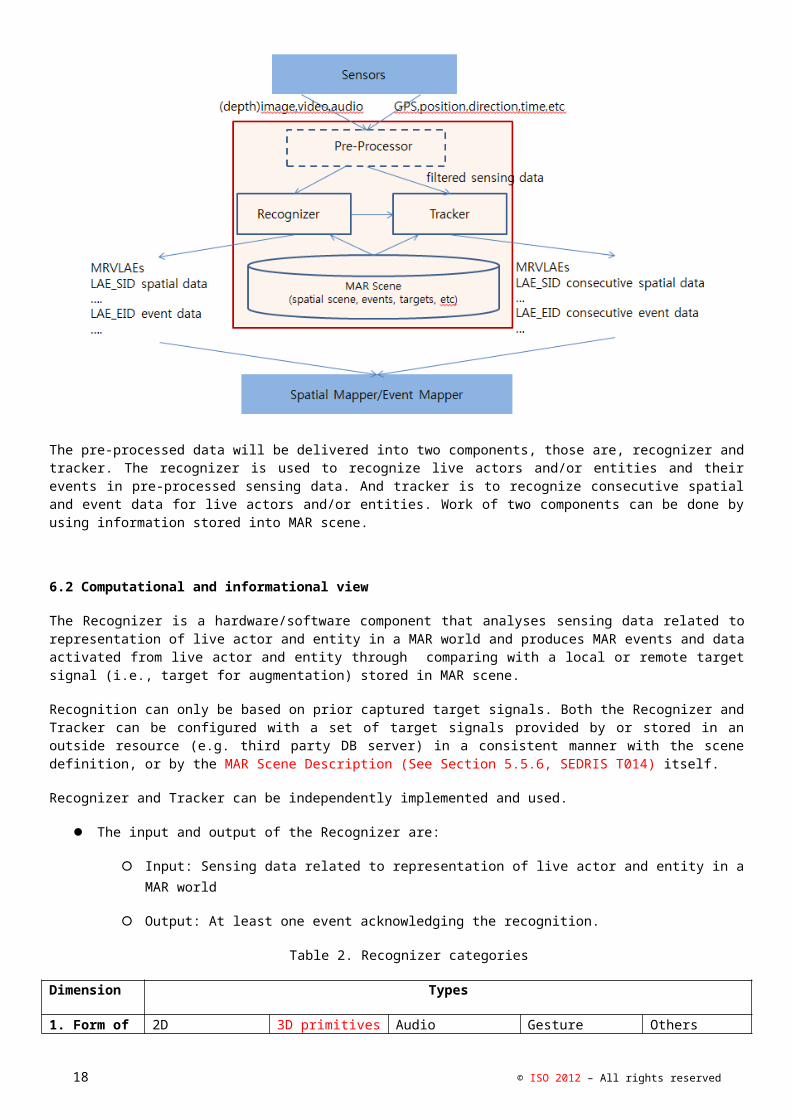
Figure 8. A procedure for controlling events of live actor and entity in an MAR world.
After the sensing of live actors and entities, the event control model proposed in Figure 8 can be concretely developed with two modules, those are, a recognition module, and an execution module. Specially, the sensing is to obtain faster and more accurate sensing data from live actor and entity themselves and their holding devices in real time. If a hand gesture is used to control events of live actor and entity, Microsoft Kinect can be employed, which allows skeleton mages of one or two persons to be tracked, as a motion-sensing input device. Position information on the left and right hands can be obtained via Kinect. A position in a 3D real space is represented by three Cartesian coordinates (x, y, depth) at each joint of the skeleton. An acquired position is first filtered to suppress image noise and then reprocessed with depth calibration and depth cueing to reduce image flickering. Kinect supports some filtering features, but the resulting object boundaries remain very unstable and flickering. After all filtering processes have been carried out, hand gestures will be recognized by a recognition module, and the recognized event will be executed by an execution module in a virtual space according to these gestures.
9.3 Computational and information view
The event relationship between a particular recognition system and a target scene is provided by the MAR Experience Creator and is maintained by the Event Mapper.
The input and output of the Event Mapper are:
Input: Event identifier and event information.
Output: Translated event identifier for the given MAR scene.
9.4 Event execution
A detected event is transferred in the event class EventClass, in an execution module. If the detected event is one of the events defined in an MAR system, the event corresponding to the recognized event will be applied to the object in the 3D virtual space by the event executor (EventExecutor). In other words, the object in the 3D virtual space will be manipulated according to the corresponding event function.
Figure 11 shows the structure for executing events to control objects in a 3D virtual space. The class EventExecutor employs registered object-control functions to control objects in a 3D virtual space, by analyzing events in EventClass. If a virtual object can be controlled by events, we set the class EventExecutor as a member of the object instance, create a callback function to be executed on the gesture event for the object, and link the generated function to a corresponding gesture delegate function in EventExecutor based on event type. Then, when an event occurs, the
18 © ISO 2012 – All rights reserved

MAR-RCRM system executes the function executeCommand(Event ge), to which the event is passed as a Event instance, and executes the generated callback function via the corresponding delegate function in EventExecutor. Accordingly, a live actor and entity can interact with 3D virtual objects in an MAR environments, just as he/she does with real-world objects.
Figure 11. Execution structure of events performed by a live actor and entity
© ISO 2012 – All rights reserved 19

10. Renderer and Simulator
10.1 Overview
The Renderer refers to the software and optionally hardware components for producing, from the MAR Scene Description (See Section 5.5.6, SEDRIS T014), updated after a tick of simulation, a presentation output in a proper form of signal for the given display device.
10.2 Computational and information view
The rendered output and the associated displays can be in any modality. When multiple modalities exist, they need to be synchronized in proper dimensions (e.g., temporally, spatially).
The input and output of the Renderer are:
Input: (Updated) MAR scene graph data.
Output: Synchronized rendering output (e.g., visual frame, stereo sound signal, motor commands, etc.).
The Renderer can be categorized in the following way:
Table 4. Renderer categories
Dimension Types
1. Modality Visual Aural Haptics Others
11. Display and UI
11.1 Overview
The Display is a hardware component that produces the actual presentation of the MAR scene to the end-user in different modalities. Displays and UI include monitors, head-mounted displays, projectors, scent diffusers, haptic devices and sound speakers. A special type of display is an actuator that does not directly stimulate the end-user senses but may produce a physical effect in order to change some properties of the physical objects or the environment. The UI is a hardware component used to capture user interaction (touch, click) for the purpose of modifying the state of the MAR scene. The UI requires sensors to achieve this purpose. However, these sensors may have a similar usage as those known as pure sensors. The difference consists then in the fact that the only physical object sensed is the user.
20 © ISO 2012 – All rights reserved

11.2 Computational and information view
The input and output of the Display are:
Input: Render signals
Output: Display output
The input and output of the UI are:
Input: User action
Output: UI event
13. Conformance
Conformance to this reference model is expressed by describing how the aspects of an MAR implementation relates to the MAR system architecture. Conformance of MAR implementations to this standard shall satisfy at least the following requirements.
- The following key architectural components, as specified in the Reference Model, shall be present in a given MAR implementation: Display / UI, Event Mapper, Recognizer, Renderer, Sensors, Execution Engine, Spatial Mapper Tracker and a mapping between a MAR implementation components and the Reference Model components can be established and evaluated.
- The relationship between the implementation of these architectural components shall conform to those in this Reference Model, as specified in 7.4 and graphically depicted in Figure 6.
- The interfaces between the architectural components of a MAR implementation shall contain and carry the information specified in 7.4 and 7.5. However, the specific content, format, data types, handshake, flow, and other implementation details is at the discretion of the given MAR implementation to meet its specific needs.
- The API for a MAR implementation shall conform to the concepts specified in 7.4.8 and 7.5 in order to ensure compatibility and software interface interoperbility between MAR implementations can be accomplished at least at the abstract API level.
Bibliography
© ISO 2012 – All rights reserved 21

Annex A. USE CASE EXAMPLES
A.1 3D Virtual Studio
There are a lot of examples where live actor and entity are embedded into an MAR world such as a virtual broadcast studio. Figure 12(a) and (b) show a live actor and entity as an announcer who is integrated with two different virtual broadcast studios. In order to visualize the live actor and entity in the studio, an MAR system captures an image including the live actor and entity by a general camera, removes background of the image, that is, process a chromakeying for the captured image, and renders a 3D virtual world where the background removal image is inserted through performing texture mapping on a polygon. Here the polygon is used as a movable region of the live actor and entity.
(a) (b)Figure 12. Two different virtual broadcast studios including a live actor and entity.
The second example shows that a live actor and entity is walking in a 3D virtual gallery, and he/she is trying to seat down a chair in the 3D virtual gallery as shown in Figure 13. Rendering of the live actor and entity is done similar to one in the above virtual broadcast studios.
Figure 13. A live actor and entity is seating down on a chair in a 3D virtual gallery.
A.2 Event mapping of live actor and entity in an MAR world
There are a lot of sensing interfaces between a live actor and entity and a 3D virtual world. In this document, we consider hand gestures of the live actor and entity himself/herself as a sensing interface. As proposed in the standard, three different content, those are, virtual cameras, virtual objects, virtual AR objects in a 3D virtual world, can be controlled through predefined hand gestures of a live actor and entity.
A.2 Controlling an interactive virtual camera by a live actor and entity
A virtual camera in 3D virtual space can be controlled based on hand gestures of a live actor and entity in a real world. The hand moving positions of a live actor and entity can be obtained from a Kinect, which is a motion sensing input device used to capture position information for tracking the user’s skeleton images. The positions are presented as the location (x, y, depth), at each joint point of the skeleton from the Kinect. Even if Kinect input devices are processing any filtering for the captured positions, the flicker on the sequence of positions can be still occurred. Two operations, depth calibration and depth cueing, for the sequence of positions are applied to reduce the flicker in a pre-processing step in an MAR_RCRM.
22 © ISO 2012 – All rights reserved

In order to more accurately recognize hand gestures of a live actor and entity, we check out the active space continuously in which the hand gestures are performed. A virtual camera will be moved according to the recognition results of continuous gestures in the valid subspace. Two, left and right, hands will be used to control a virtual camera in an MAR-RCRM system. Twenty four kinds of hand gestures can be created if four movement vectors, those are, upper, lower, left and right vectors, of two hands are combined. When two hands are independently moved into any place each other, 16 (=4x4) gestures can be created since the movement vectors are simultaneously achieved. On the other hand, when one hand is fixed and another is moved, 8(=2x4) gestures are created. In an MAR-RCRM system, only six gestures of twenty four will be defined in Table 1.
TABLE 1. Hand gesture types and their explanation of a live actor and entity for controlling a virtual camera in an MAR-RCRM application
Gesture Types Explanation
G1(left rotation of a camera) Actions of moving the right arm to the right direction, while holding the left arm.
G2(right rotation of a camera) Actions of moving the left arm to the left direction, while holding the right arm.
G3(up rotation of a camera Actions of moving both the left and right arms to the up direction.
G4(down rotation of a camera) Actions of moving both the left and right arms to the down direction.
G5(zoom-in of a camera) Actions of outstretching both left and right arms.
G6(zoom out of a camera) Actions of pursing both left and right arms
In order to simulate the six events using hand gestures of a live actor and entity, gestures events as shown Figure 14 can be defined with the movements of two hands. For an example, a left rotation of a virtual camera will be performed by recognizing that a left hand moves in the left direction and a right hand is fixed. In order to do the recognition more better, we assume that center position of a virtual camera, which is always looking to the origin of the 3D virtual space with fixed up vector, can be placed at any location of the 3D virtual space. In this situation, the center position will be transformed according to actions of the suggested gestures. To simulate naturally the movement of the camera, first of all, we have to consider the movement of gestures. Assume that the current position of a hand is located at any position in a 3D virtual space. When the movement position of the hand is escaped out of the designated circle with its center and its radius, the movement will be detected and one of four locations, left, right, up, and down which are defined according to the relative position from the located position will be returned.
Figure 14. Gestures events for controlling a virtual camera in an MAR-RCRM system
© ISO 2012 – All rights reserved 23

A live actor and entity has performed one of six kinds of gestures while seeing the rendering scenes for controlling a virtual camera in the 3D virtual space. Figure 15 (a) shows the results executing gestures to give left rotations for center position of the virtual camera after designating an initial position of a live actor and entity. Two figures in Figure 15 (a) show that the left hand model is moved to left direction. In the similar method, Figures 15 (b), (c), (d), (e) and (f) show the rendering scenes while applying five gestures, for controlling right rotation, up rotation, down rotation, zooming in and zooming out of the camera, respectively.
(a) left rotation
(b) right rotation
(c) up rotation
(d) down rotation
(e) zooming in
24 © ISO 2012 – All rights reserved

(f) zooming out
FIGURE 15. Examples after applying hand gestures into a virtual camera in an MAR-RCRM system
A.3 Interactive controlling of a virtual object in a MAR world by action of a live actor and entity
Hand gestures of a live actor and entity are able to control virtual objects in 3D virtual environments in a manner similar to the virtual camera control illustrated in Section 8.2.1. The hand gestures can be obtained by using a Kinect device. Seven gestures events as shown Figure 16 can be defined with the movements of two hands. For an example, a right rotation of a virtual object will be performed by recognizing that a right hand moves in the right direction and a left hand is fixed.
Figure 16. Gestures events for controlling a virtual object in an MAR-RCRM system
© ISO 2012 – All rights reserved 25

Fig.17 shows the simulated replacement of a flat tire on a virtual car with a spare tire from the virtual trunk. Fig. 17 (a) shows the initial 3D virtual space in which the virtual car is located, together with flesh-colored virtual left and right hand gestures for controlling the virtual object (car). When a hand of a live actor and entity is located in the inactivation area or no gesture is made, the virtual hand remains flesh colored. If a hand of a live actor and entity enters the activation area, the virtual hand begins to turn red. The virtual hand is completely red and is surrounded by four arrow keys, indicating that the gesture recognition system has begun to recognize the hand gesture, as shown in the right-hand part of Fig. 17 (c). If a user hand enters the object-selection area, the virtual hand begins to turn blue. If the hand is completely blue and surrounded by four arrow keys, the virtual object at the hand position is selected and can be manipulated via real-world hand gestures. To replace the flat tire, we first remove the flat tire from the virtual car, open the virtual trunk, extract the spare tire, and set it on the ground. In Fig. 17 (d), both blue hands hold the spare tire and push it closer to the virtual car. The tire is then set upright with the left hand and attached to the appropriate wheel on the virtual car. Thus, a virtual flat tire on a virtual car in a virtual space is replaced with a virtual spare tire from the virtual trunk. Fig. 17 (e) and (f) show examples of opening a door on the virtual car and selecting a seat (e) and controlling the audio system while sitting in the seat (f). Fig. 17 (g), (h) and (i) show examples of simulated engine disassembly on a virtual car.
(e) (f)
26 © ISO 2012 – All rights reserved

(g) (h) (i)
Figure 17. Examples of virtual objects by hand gestures of a live actor and entity in an MAR-RCRM system
A.4 Augmenting a real object with special effects
Gestures of a live actor and entity are able to augment virtual objects in 3D virtual environments in a manner similar to other operations. The gestures can be obtained by using a KINECT device. Three gestures events as shown Figure 18 can be defined with the movements of two hands and two arms. In order to augment a water animation over the left hand of a live actor and entity, for an example, we use both spread actions of bended left arm and bended fingers. Similarly, the fire animation can be simulated by using the spread gestures of right arm and right fingers. The animations will be continued until the disappearing gestures are recognized. The disappearing gestures can be defined as actions conversing two hands.
Figure 18. Gestures events for controlling au augmented object in a MARRC-RM system
Fig.19 shows the simulated replacement of a flat tire on a virtual car with a spare tire from the virtual trunk
© ISO 2012 – All rights reserved 27

(a)
(b)
28 © ISO 2012 – All rights reserved

(c)
A.5 3D virtual teleconference
© ISO 2012 – All rights reserved 29