basic scattering theory - university of york
TRANSCRIPT


Kevin Cowtan, [email protected] York 2009
Waves and interference.
Bragg's law.
The Fourier Transform.
Outline

Kevin Cowtan, [email protected] York 2009
X-rays Scattering Describing waves
The Argand Diagram Interference
Waves


Kevin Cowtan, [email protected] York 2009
X-ray ScatteringX-rays and matter... Electromagnetic rays interact with anything
electrically charged, particularly if the 'size' is similar to the wavelength.
X-rays interact with electrons, especially those localised around atoms, whose size is ~1Å (10-10m).
An X-ray is scattered in a predictable manner by a free electron (elastic scattering). Atomic electrons are not free, but the behaviour is similar.
The interaction is very weak: to get observable scattering, there must be a great many scattering atoms. To get informative scattering, there must be many scatterers in similar environments – a crystal.

Kevin Cowtan, [email protected] York 2009
X-ray scatteringDiffraction experiment...
Incident beam Through beam
Scattering

Kevin Cowtan, [email protected] York 2009
X-ray scatteringX-rays: Waves or particles? No. These are just 'pictures'.
− What is actually going on can be 'described' by the mathematics of quantum mechanics.
However, for the purposes of understanding x-ray scattering from a crystal, the 'wave' picture is helpful most of the time.
− Treat X-rays as electromagnetic 'waves'.− All the X-rays are scattered by all of the electron
density.− Multiple X-rays arriving at a detector interfere
constructively or destructively.

Kevin Cowtan, [email protected] York 2009
X-ray scatteringX-rays: Waves or particles? No. These are just 'pictures'.
− What is actually going on can be 'described' by the mathematics of quantum mechanics.
However, for the purposes of understanding x-ray scattering from a crystal, the 'wave' picture is helpful most of the time.
− X-rays are electromagnetic waves.− All the X-rays are scattered by all of the electron
density.− Multiple X-rays arriving at a detector interfere
constructively of destructively.

Kevin Cowtan, [email protected] York 2009
Waves:Properties of a wave:
wavelength
amplitude
phase
For most of the experiments we perform, we use monochromatic x-rays, so wavelength is a constant.The remaining properties are amplitude and phase. These two values (along with position and direction) define the wave.


Kevin Cowtan, [email protected] York 2009
Waves:
The amplitude of a wave describes how high the peak and troughs are: It is related to the strength of the electromagntic radiation.
It is always positive.
Amplitude:

Kevin Cowtan, [email protected] York 2009
Waves:
The phase of a wave describes where the peaks and troughs are located (relative to some arbitrary reference position).
Phase is cyclic – if the wave is shifted by one complete wavelength, then you get back to where you started.
Phase:

Kevin Cowtan, [email protected] York 2009
Waves:So a wave can be represented by two numbers: a positive amplitude, and a cyclic phase. Angles are cyclic: they repeat after 360° (2π
radians). Therefore, it is often convenient to represent
the phase of a wave as an angle, with 360° scaled to represent a single wavelength.
The wave can therefore be written in terms of a trigonometric function:
f(x) = cos( 2π x / λ )

Kevin Cowtan, [email protected] York 2009
Waves:A positive number and an angle can be combined to describe any position in a 2D plane, using polar coordinates:
(x,y) = ( √3/2, 1/2 )(r,φ) = ( 1, 30° )
x
y

Kevin Cowtan, [email protected] York 2009
Waves:So, to describe our wave, we will use polar coordinates to describe the properties of the wave.
x
y120°
360°
22 120°

Kevin Cowtan, [email protected] York 2009
Waves:Our wave is described by the numbers (2,120°).We will use the letter F to describe the wave as a whole.Then, the amplitude will be|F|, and the phase will be φ.F = ( |F|, φ )
x
y
2 120°

Kevin Cowtan, [email protected] York 2009
Waves:Another way of representing the same information is in the complex plane (or Argand diagram). The wave can now be represented by a single complex number, with real and imaginary parts:F = A + i BF = |F| exp( i φ ) (for φ in radians)F = -1 + 1.732 iF = 2 exp( i 2π/3 ) This is very useful!
real
imaginary
2 2π/3

Kevin Cowtan, [email protected] York 2009
X-ray scatteringDiffraction experiment...
The incident beam is assumed to be coherent (within certain bounds), i.e. the waves are all in phase.
In the scattered beam the waves are no longer in phase.


Kevin Cowtan, [email protected] York 2009
InterferenceWhat happens when multiple waves combine? We can determine the amplitude and phase
of the combined wave by adding the complex numbers, or equivalently, by adding the vectors in the Argand diagram.
+ =

Kevin Cowtan, [email protected] York 2009
WavesSummary: X-rays share some behaviors with waves. A wave can be described as a complex
number, i.e. a vector in the Argand diagram. Waves can interfere with each other
constructively or destructively dependent on their relative phases.
The resultant wave may also be determined by adding the vectors in the Argand diagram.

Kevin Cowtan, [email protected] York 2009
The crystal lattice Diffraction of X-rays from a crystal Diffracting planes, and their indices
Bragg's law


Kevin Cowtan, [email protected] York 2009
The Crystal LatticeDescribing the lattice: In 2D: a, b, α
− α is the angle between a and b In 3D: a, b, c, α, β, γ
− α is the angle between b and c− β is the angle between c and a− γ is the angle between a and b
a
b
c β
γα

Kevin Cowtan, [email protected] York 2009
X-ray scatteringDiffraction experiment...
Unit cells are much smaller than detector pixels. Thus essentially parallel beams from nearby cells combine to contribute to the signal at the detector.Scattering occurs in all directions, but we will consider one direction to analyse the resulting signal.

Kevin Cowtan, [email protected] York 2009
Bragg's lawConsider diffraction from two planes of atoms:
θθ
d
2d sin θ
The diffracted beams are in phase (i.e. strong diffraction) when the path difference is a whole number of wavelengths, i.e. nλ = 2d sin θ
θ θ

Kevin Cowtan, [email protected] York 2009
Bragg's lawnλ = 2d sin θ
Notes: The beam is diffracted through an angle 2θ. Even with λ fixed, we can probe features of
different spacing d by changing sin θ. Smaller features (lower d) lead to a greater
angle of diffraction (larger sin θ). The smallest features we can sample are
when sin θ = 1, i.e. θ=90°, 2θ=180°. We cannot resolve any feature smaller than
λ/2 (since λ/2d < 1).


Kevin Cowtan, [email protected] York 2009
Bragg's lawWe get diffraction when there are set of repeating planes of atoms in the crystal. The crystal lattice leads automatically to
many such repeating planes being present.− However there are lots of different possible sets
of planes.− We need a way of naming the sets of planes

Kevin Cowtan, [email protected] York 2009
Bragg's lawName each set of planes according to the number of times a plane cuts the a and b cell vectors: Call these numbers (h,k). These are Miller
indices. In 3D, we have
(h,k,l).
a
b
(1,0)
(0,1)
(1,2)

Kevin Cowtan, [email protected] York 2009
Bragg's law
θ θ
2θ Scattering vector
Note: the scattering vector (the change in beam direction) is always perpendicular to the planes. Therefore, it is useful to define vectors to define scattering directions which are orthogonal to the original cell vectors. These will be reciprocal cell vectors: a*, b*, c*
Kevin Cowtan, [email protected] York 2009
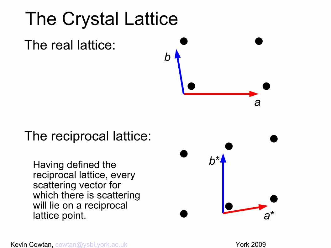
The Crystal LatticeThe real lattice:
The reciprocal lattice:
a
b
b*
a*
Having defined the reciprocal lattice, every scattering vector for which there is scattering will lie on a reciprocal lattice point.

Kevin Cowtan, [email protected] York 2009
Bragg's lawSummary: The crystal lattice provides sets of planes
which repeat through the crystal. These planes can be labelled by Miller
indices (h,k) in 2D or (h,k,l) in 3D. Bragg's law tells us that more closely spaced
planes lead to greater angles of diffraction.
Bragg's law tells us where we get diffraction spots, and the Miller indices give us a way to label them. But it tells us nothing about the strength of the different spots. That is determined by the contents of the unit cell. This requires the Fourier transform.

Kevin Cowtan, [email protected] York 2009
Fourier transforms allow us to describe an arbitrary function in terms of waves.
The diffraction pattern is the Fourier transform of the electron density.
The 3D plane waves are a more general description of the Bragg planes.
The Fourier transform can also be used to go from the diffraction pattern back to the electron density.
Fourier Transforms

Kevin Cowtan, [email protected] York 2009
Fourier TransformsAssertion: Any function can be described as the sum of waves of different amplitudes, phases, and wavelengths.
Consider a 1D crystal structure with 3 Atoms


Kevin Cowtan, [email protected] York 2009
Each wave contains some elements of the initial function. However none of them can describe all the features of the original function.
What happens if we add them together?


Kevin Cowtan, [email protected] York 2009
Fourier transformsThe Fourier transform is a mathematical transformation which turns a function into a set of waves which sum to produce that function. Decomposing the electron density in terms of
waves models diffraction, because we are using waves to probe the crystal.
− Although we use different angles instead of different wavelengths.

Kevin Cowtan, [email protected] York 2009
Fourier transformsThe Fourier transform is a mathematical transformation which turns a function into a set of waves which sum to produce that function. One of its properties is that it is self-inverse
(ignoring a reflection through the origin). Apply the Fourier Transform twice, and you
get back to where you started. However: We can measure the intensity of
the diffracted wave, but not its phase.− The phase problem in X-ray crystallography.

Kevin Cowtan, [email protected] York 2009
Fourier transformsThe scattering from a 3D solid is always the Fourier transform of the scattering matter, where the scattering vector in 3D is the difference between the incident and scattered beam vectors.Let the incident beam direction be represented by a vector k. The diffracted beam along the chosen direction will be k'. For convenience, we set the magnitude of these vectors to the reciprocal of the wavelength of the beam.
Now we must sum the scattering from the whole solid. First, we pick an origin within the solid. Then, we calculate the difference in path length between a beam scattered from an arbitrary point in the solid and an imaginary beam scattered from the origin.
This difference in path length is translated into a phase difference between the two waves. We can then sum the scattering over the whole solid, taking into account the strength of scattering from each point, p(r), and the complex representation of the phase shift. If we substitute a new vector s for the difference between k and k', then we obtain a standard Fourier integral:


Kevin Cowtan, [email protected] York 2009
Fourier transformsAn molecule and it's Fourier transform...

Kevin Cowtan, [email protected] York 2009
Fourier transformsAn lattice and it's Fourier transform...

Kevin Cowtan, [email protected] York 2009
Fourier transformsAn crystal and it's Fourier transform...

Kevin Cowtan, [email protected] York 2009
Fourier transformsAn duck and it's Fourier transform...
Note Hermitian symmetry.

Kevin Cowtan, [email protected] York 2009
Fourier transformsAn duck and it's Fourier transform...
High resolution terms missing.

Kevin Cowtan, [email protected] York 2009
Fourier transformsAn duck and it's Fourier transform...
Low resolution terms missing.

Kevin Cowtan, [email protected] York 2009
Fourier transformsAn duck and it's Fourier transform...
Segment of data missing.


Kevin Cowtan, [email protected] York 2009
The diffraction pattern is the Fourier transform of the electron density.
The crystal lattice in real space leads to diffraction spots in reciprocal space.
We can Fourier transform the diffraction pattern to get the electron density.
− But only if we can determine the unmeasured phases.
Fourier transforms