basic sanitation training manual excreta disposal … · excreta disposal and sewerage...
TRANSCRIPT

^. ' - "\
SRI LANKA I3S2-/23
THE NATIONAL WATER SUPPLY
AND DRAINAGE BOARD
MARKET TOWN WATER SUPPLY JAFFNA PROJECT
BASIC SANITATION
TRAINING MANUAL
EXCRETA DISPOSAL AND SEWERAGE i t . . r \p.V
,,, _ , -.1 v'-t?i'"'ce L-on'---
AID PROJECT NO. 383-0063
125
4 2 /
ENGINEERING -DESIGN • RESEARCH
WEST HUNTINGTON DRIVE • P.O. BOX 338 • ARCADIA,
COLOMBO , HORTON PLACi
SCIENCE < PLANNING
CALIFORNIA 91006 • 2 1 5 / 4 4 5 -
JAFFNA 8 2 , KACHCHERt-NALLUR
7 3 6 0
ROAD
^10-^2N)-I3sz

320 8z bf>
MARKET TOWN WATER SUPPLY - JAFFNA PROJECT
BASIC SANITATION TRAINING MANUAL
EXCRETA DISPOSAL AND SEWERAGE
prepared for
THE NATIONAL WATER SUPPLY
AND DRAINAGE BOARD
Liry-.r-Y,; "-••",.•. \ • .. .
*':!-, -.• . • •••:'•:•• . . .. v.;• j r f L Y
i . . • _ . . , , , . • . ' .* *
! :".. V '..•'.•'• •-. '-: Jl-1 /'-'J ii": : r: :yi«
.'J. .„.• '."•. '-3. :.•; il e..\. 1-H;:': >
- 3 - 2 . 0 ' a a 8 Q ••
September 1982
i
IJ3RARY international jftoterencs Csnfr« lor Communis 'v.;1-:-' '*; . >• '
prepared by
ENGINEERING-SCIENCE 42/1 Horton Place, Colombo 7.
32, Kachcheri-Nallur Road, Jaffna

TABLE OF CONTENTS
Page
Objectives 1
Health and Nuisance of Excreta Disposal 1
Alternative Systems 2
Precautions 5
Definitions 5
Disposal of "Septage" 6
Raised Units 6
Dual Systems 6
Privy Vaults 6
Liquid Waste Disposal 9
Definitions 9
Septic Tank System for Modern Water-Flush Plumbing 11
Cleaning of Septic Tanks 11
Percolation Tests 13
Determining Si2e of Absorption Systems 18
Seepage Pits 19
Special Precautions 24
Special Type Soil Absorption Systems 24
Other Design Factors 25
Summary of System Design 26
Absorption System 2 7
Disadvantages of Activated Sludge Systems 28
Conventional Public Sewers and Sewage Disposal 30
Special Sewers 30
Public Sewage Disposal 30
Septic Tanks 30
Stabilization Ponds 31
Conservancy Systems 33
Underground Travel of Contamination 36
Direction of Travel 36
Filtration In Soils 36
Conclusions - For Granular Soils 37

TABLE OF CONTENTS (CONTD.)
Contamination Travel In Rock
Soil and Groundwater Investigations
Volumes of Excreta From Pour-Flush Systems
Aqua Privy
Special Studies of Soil And Geology
Test Holes
Other Observations
p ri L) e N o
3 7
38
3 9
3 9
40
4 1
4 1

LIST OF FIGURES
Page No
1. i Vacuum Tanker 3
2. Septic Tank for Pour Flush Latrine 4
3. Soakage System For Pour Flush System 7
4. Jaffna CPHI Double Vault 8
5. Typical Two Compartment Septic Tank 12
6. Procedures For Making Percolation Test 14
7. Percolation Test Procedures 16
8. . Chart For Determining Square Feet of
Absorption of Area 17
9 . Seepage Pit 2 0
10. Seepage Pits in Fine Soil 2.1
11. Seepage Pit 22
12. Seepage of Soakage Trench or Bed 2 3
13. Aerobic System 29
14. Stablization Pond Design 32

BASIC SANITATION TRAINING MANUAL
EXCRETA DISPOSAL AND SEWERAGE
OBJECTIVES''-
The Project is intended to provide plans, advice and
training in both water supplies and sanitation (excreta and
sewage disposal).
The Introductory Training Manual provides information on
the total Project and covers the public health aspects of both
the water supplies and sanitation.
The Water Supply Manual is intended for water system
managers, supervisors, designers, operators and surveillance
personnel.
This Basic Sanitation Manual is intended to provide
guidance for planning, designing, building and maintaining
the various systems for excreta and sewage disposal.
The manuals will be supplemented by classroom,
laboratory and field training programs.
HEALTH AND NUISANCE ASPECTS OF EXCRETA DISPOSAL
The Introductory Training Manual covers the health
aspects of excreta disposal. The problems include:
1. Pathogens from excreta and sewage entering the
limestone and travelling considerable distances to
contaminate public and private drinking water supplies.
1

2. Intestinal parasites from excreta contaminating the
soil and surfaces and resulting in excessive cases of
hook, round, whip and other intestinal worms.
(Intestinal parasites).
3. Fly transmission of pathogens from exposed excreta
to food.
4. Sea and beach contamination by defecation (excreta)
which contaminates sea foods.
5. Odor nuisances and unsightly conditions.
ALTERNATIVE SYSTEMS
Conservancy System - The bucket system is the best presently
available system for excreta collection, transportation and
disposal for homes and businesses where there is not room and
suitable conditions for pour-flush latrines.
This Manual suggests improvements for this system.
It is* .strongly recommended that the Conservancy System
not be abandoned until a suitable substitute system is
available.
Pour-Flush (water-seal) Latrine - The W.H.O.
publication on Excreta Disposal,written in 1958, credited Ceylon
with having pioneered in this system 25 years bet ore the book
was written. Field training for masons and carpenters will
cover certain basic principles. Some of those are illustrated
in the following drawings from the Introductory Training Manual.
The Vacuum Tanker, which is proposed to help improve
the Conservancy System operations, would be very useful for
emptying the vaults of pour-flush toilets (Figure 1).The Consul
tant reviewed the program in Bangkok where 100 such trucks are
2

FIGURE
v e n t , " 7 5 m m .
h o u s e
v a c u u m t a n k e r
m a n h o l e m
: v o u l t r =
ffi^S^B
v e n t
h o u f l o
/ / h o w ) t o t a n k e r
V O U I t . r .
VACUUM TANKER
RDC/EW ENGINEERING - SCIENCE

MANHOLE
3 <=t> TO SOAKAGE TRENCH, PIT OR BED
I-11/2 M
SEPTIC TANK FOR POUR FLUSH LATRINE

used to pump out such vaults, as well as septic tanks.
PRECAUTIONS
The precautions covered below under septic tank "Absorption
Systems" also apply to pour-flush and water-sealed latrines.
These include precautions against drainage of fecal material
and liquids into limestone.
DEFINITIONS
Privy - A hole in the ground to directly receive human wastes.
There are new modern privies designed to reduce odors
called VIP (Ventilated Improved Privy).
Bored hole latrine - A simple, but not fully satisfactory,
12 to 20 inch diameter hole, 10 or more feet deep, used as
a privy.
Pour-Zlush (water-sealed) Latrine A squat-plate type toilet
with a "u-shaped" trap which prevents escape of odors from
the pit, vault or septic tank(See Figure 2) .
Pit Privy - Four or more feet deep and three feet square or
larger with seat or step plates. Seat with hinged, self-
closing cover to keep pit fly-tight.
Aqua privy - Usually a concrete tank about rhree feet
square and three feet deep, water tight, will; overflow near
top, with liquid draining to seepage pit or sewer.
Designed with tube from underside of floor to beneath water
level to confine air above liquid (odor control). Flush
with a few liters of water per day (popular in some new
villages in countries like Kenya).
r,

DISPOSAL OF "SEPTAGE"
The mixture of excreta and water from a pour-flush latrine
vault or a septic tank should either be buried where it will not
contaminate groundwater; or should be plowed under on land
which will not soon be used for vegetable crops.
RAISED UNITS
Note the following sketch (Figure 3) which indicates how to raise
the squat-plate and latrine floor high enough to permit making a
20 to 24 inch sand fill below the drain system, if in an area
of shallow soil cover over limestone or high groundwater.
DUAL SYSTEM
The illustration of a system with a dual vault (Figure 4)and a
"diversion box" is important. When one vault fills, the flow
can be diverted to the other. Then, in the usual many months
until the second vault fills, the material in the first vault
can drain (if in somewhat porous soil) and become dry and
"digested" to make it less odorous and easier to remove than the
wet mixture of water and excreta.
PRIVY VAULTS
For some families it may be a burden to carry enough extra
water'•••from a distant standpost or well, to flush the latrine.
They may w '„.'•. to consider a simple pit privy.
6

8 m
9 0 cm. ^
°o°%>oa * o 0 o o
SEEPAGE PIT
C- o
^ c 30 cm.
W;/'MAVWWAVvW<iMJJWM^;WMJ^^;*»m.«i^F^.»vu>wuyjMtti»-S
Q ~ ^ r~>Q O P r?
GRAVEL FILLED TRENCH OR BED
- ^ h
m
I1 z m m
~Z-(D
O) O
m z o m
FILL
5^M
GRAVEL
"GR0UH0
SURFACE
= 3 T €J?^L 53£&i£3 )'X*J,l*/f,kl*>A- liUitMtA~ll»<WJAT~*S<l<L*i>*-'<t*VrM*->if Jf.
f SANDY SOIL
TOP SOIL
4 1 SLOPE
50+ cm.
X LIMESTONE OR HIGH WATER LEVEL
MOUND SYSTEM
SOAKAGE SYSTEM FOR POUR FLUSH SYSTEM
Z3 o c 3D m en

JO o o
m 3S
m 2 SI 2 m m
2 O
i C/>
o m 2 O m.
SQUAT PLATE
"DAM*
/
FOR COK:RETE TOP
CKVERSJON BOX
TOP VIEW
A
/
" ' ! ^ - ( 4 " PIPE WITH 1
/ ~ ,H\H% 5 V. SLOP€ |
• r • , ! -
1 y^WATJERTJGHT_ — | / WALL 1
i / 1
1 i
—L 4--J- WALLS Of LOOSE I
u - > ^ 7 - B R I C K 7 _ S T O N E : ~ O R
""' ' HOLES IN CONCRETE*-—^
—
i
i
co
OJ
, A
CM
1 6'-0" ±
DOUBLE SOAKAGE PIT
) - i
5 7. SLOPE
REBARS
\
JAFFNA CPHI DOUBLE VAULT NOTE : I. ONE VAULT DRIES WHILE OTHER FILLS
2. DRIED VAULT IS THEN DUG OUT.
-y^-
iND
,OP£N .'90TT-04-,
Oi _ i i
m | . 1 i
"ol
I
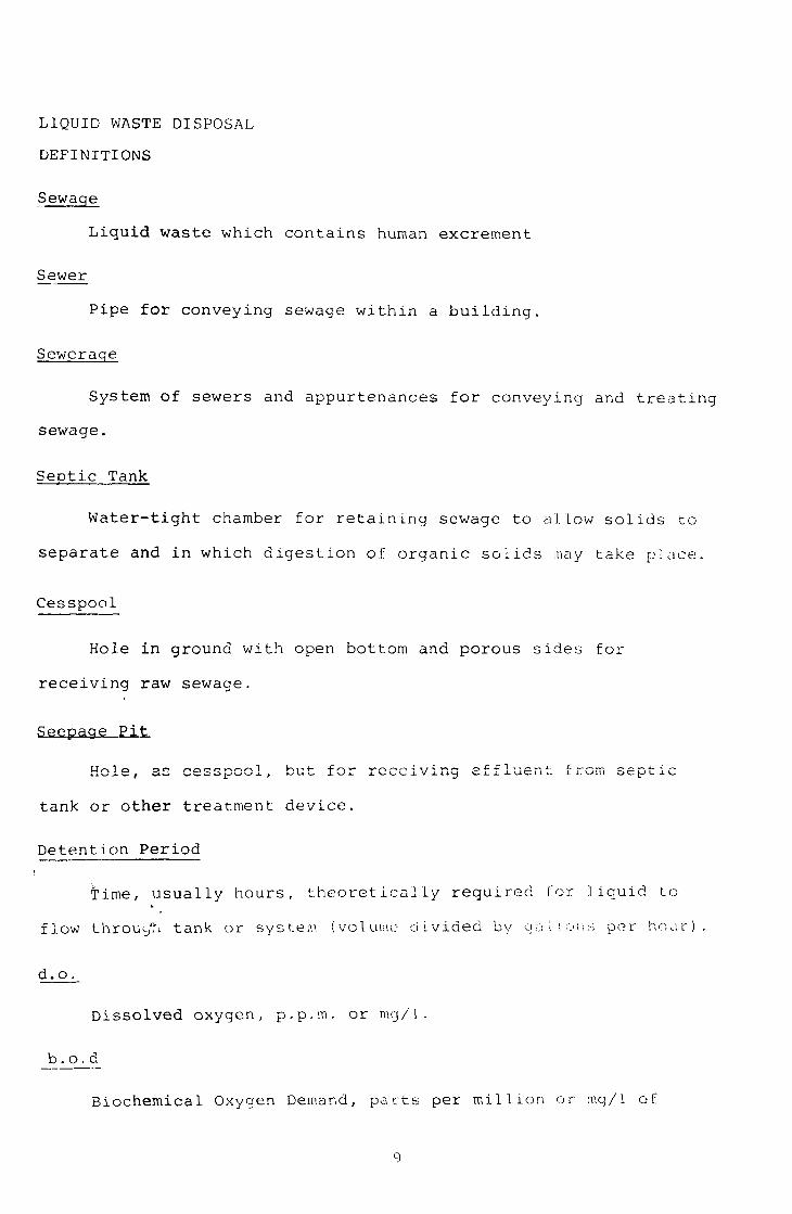
LIQUID WASTE DISPOSAL
DEFINITIONS
Sewage
Liquid waste which contains human excrement
Sewer
Pipe for conveying sewage within a building.
Sewerage
System of sewers and appurtenances for conveying and treating
sewage.
Septic Tank
Water-tight chamber for retaining sewage to allow solids to
separate and in which digestion of organic solids may take place.
Cesspool
Hole in ground with open bottom and porous sides for
receiving raw sewage.
Hole, as cesspool, but for receiving effluent: from septic
tank or other treatment device.
Detention Period
Time, usually hours, theoretically required for liquid to
flow through tank or system (volume divided by go!ions per hour).
d. o.
D i s s o l v e d oxygen , p . p . m . o r n ig /1 .
b . o_j_d_
Biochemical Oxygen Demand, parts per million or ir.g/1 of
9
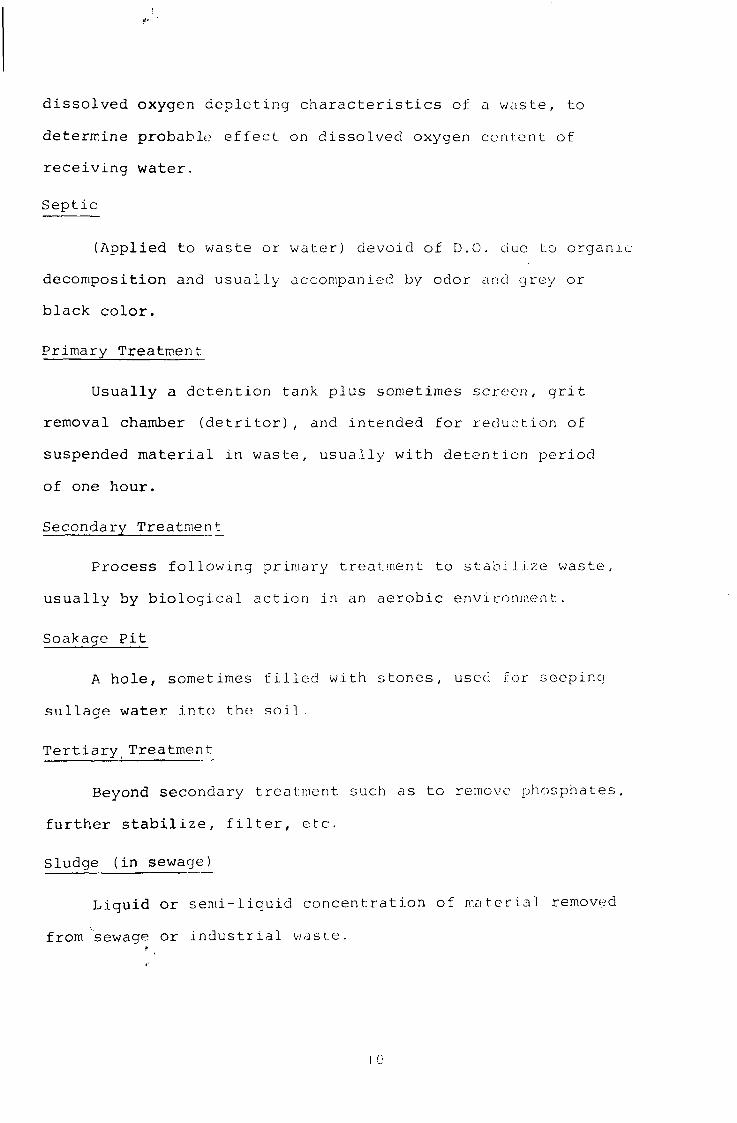
dissolved oxygen depleting characteristics of a waste, to
determine probable effect on dissolved oxygen content of
receiving water.
Septic
(Applied to waste or water) devoid of D.O. due to organic
decomposition and usually accompanied by odor and grey or
black color.
Primary Treatment
Usually a detention tank plus sometimes screen, grit
removal chamber (detritor), and intended for reduction of
suspended material in waste, usually with detention period
of one hour.
Secondary Treatment
Process following primary treatment to stabilize waste,
usually by biological action in an aerobic environment.
Soakage Pit
A hole, sometimes tilled with stones, used for seeping
sullage water into the soil.
Tertiaryr Treatment
Beyond secondary treatment such as to remove phosphates,
further stabilize, filter, etc.
Sludge (in sewage)
Liquid or semi-liquid concentration of material removed
from sewage or industrial waste.

1
SEPTIC TANK SYSTEM
FOR MODERN WATER-FLUSH PLUMBING
Cesspools are not recommended because grease and solids
from sewage tend to plug the pores in the soil. To help prevent
such plugging, septic tanks are used to provide an opportunity for
the sewage to be retained for about 24 hours so heavier-than-water
material w;,,i.l sink and light material float while the relatively
clear water between flows to the subsurface absorption (liquid
disposal) system.
Septic tanks are usually of concrete and hold 700 to 1,000
gallons for the average home. The top is arranged to be removable
or with manhole openings so sludge may be removed every few
years or more often. The solids tend to digest, to reduce
their volume by about 50 per cent. Many codes require the
tanks to have two compartments,- the first being 2/3 and the
second 1/3 of the tank volume (See Figure 5).
The effluent contains dissolved organic material, has a
typical sewage-type odor and may contain pathogens;. It must
usually be disposed of by absorption beneath the ground surface
in a seepage pit or a disposal bed or trench. If possible,
the liquid should not flow into streams, lakes, the ocean,
nor into open street-side drains (odor problems). The size,
design and location of the subsurface liquid absorption system
depends upon soil and groundwater conditions.
CLEANING OF SEPTIC TANKS
'• Septic tanks partially digest organic solids and grease
.1 J

TYPICAL TWO COMPARTMENT SEPTIC TANK
••"•SC-:
COMPARTMENT BAFFLE OUTLET BAFKLE
T:-'-& S
INLET
trt:
to Mmm^ X » -a. ki a
SCUtf
• - - J £ - - -- — ~—mk. ~.T.^_-
CLEAR SPftCE
• • • ^ • • i ^ . >
? > ^ " - - : : - ^ / " " ; : " : - ' : • • • • ' : : ' • •
O | G
U1

but do eventually fill to the point where solids pass thrqugh
the outlet. The frequency of cleaning depends upon the tank : i
size and the number of persons using the system; therefore, the
usual frequency varies from once in one year to once in five
years.
Both the floating scum and the settled solids must be
removed so it is usually necessary to mix solids and liquid
and empty the tank. The removed solids (septage) can be spread
and plowed into land not used for vegetables.
PERCOLATIOB TESTS
Soil examination in special test holes is usually necessary
to determine the soil "percolation" suitability. The test* holes
also show depth to rock formations and groundwater. "Percolate"
means to slowly seep through.
To obtain additional data on soil porosity, percolation
tests are made at the location and depth where the sewage
disposal system would be installed. The test is conducted to
to provide a rate at which water seeps into the soil, and is
measured as the number of minutes required for the water level
in the test hole to drop one inch.
13

FIGURE 6
A ^ ' / --
PROCEDURES FOR MAKING PERCOLATION TESTS
RDC/EW ENGINEERJNG-SCIENCE

The hole is dug with a diameter of 6 to 12 inches. Two
inches of small stones are placed at the bottom. The hole;
walls are ''scarified" (scraped to roughen surface) if the soil
contains clay. If soil is so sandy the walls cave, no tes t
is necessary and the rate is less than 10 minutes per inch.
It is usually necessary to soak the soil before recording
the timing of the rate of percolation. This can be done by
soaking for a few hours by keeping the hole at least partly
filled. Then the rate is timed until it becomes quite constant
(in minutes per inch of drop of water level) .
The test is usually finally made by filling the
hole to about 12 inches deep above the 2 inches of
stones in the bottom. Time is recorded each 10 to 30 minutes
until the hole is nearly empty. Results are averaged to give
the rate in "minutes per inch". If the rate is over 60 minutes
per inch the soil is usually classed as "unsuitable". If may
be somewhat acceptable for liquid from pour flush latrine^
at rates up to 120 minutes per inch (See Figure 6). Typical.
The "minutes-per-inch" obtained from the above "average"
is used in connection with Figure to find the number of
"square feet of absorption area required. That means any of
the following:
••. 1. Square feet of trench bottom.
2. l-'Jil 50% to get square feet of seepage bed bottom' areas
3. Square feet of side-well area of seepage nit, below
level of inlet.
15

FIGURE 7
PERCOLATION TEST PROCEDURES
- 6" TO I a" DIA.
TOP VIEW
READ WITH BOTTOM
AT WATER LEVEL
RULER
-vsA_/VA~A^_/L
WAVER LEVEL-START OF TEST
WIRE
SCREECH-IP NECESSARY) TO SUPPORT WALLS
SMALL STONES
BOTTOM OF TEST HOLE TO BE AT ELEVATION Or PROPOSED
SEEPAGE SYSTEM BOTTOM
TEST PROCEDURES
1. ROUQEN WALLS OF HOLE AFTER EXCAVATION.
2. FILL AND REFILL TO ALLOW HOLE TO SOAK THROUGHLY.
3. READ RULER EACH 10 TO 30 MINUTES.
4. CONTINUE TEST UNTILL WATER LEVEL IS ONE INCH ABOVE ROCK.
5. AVERAGE READING RESULTS TO GET "AVERAGE" MINUTES FOR
WATER LEVEL TO FALL ONE INCH.
6. USE CHART (FIG- ) TO FIND REQUIRED SIZE OF PERCOLATION
AREA IH SQ.FT.
16 ENGINEERING-SCIENCE

FIGURE 8
o DC
I UJ
<
oc
z
3 -J <
8
6
4
2
0
t
II
1 X ^
•
—T— . —
^
1—- . —J
10 20 30
MINUTES PER INCH
40 SO 60
CHART FOR DETERMINING SQUARE FEET
OF ABSORPTION AREA
RDC/ EW E N G I N E E R I N G - S C I E N C E

DETERMINING SIZE OF ABSORPTION SYSTEMS
Pits
Assume percolation test indicates 150 square feet of
seepage area is required.
Assume pit will be 5 feet in diameter.
.How deep must pit be? *
Area (A) •-"'' DH
H = A = 150 = 150 =10' deep.
D 3.1416x5 15.7
Tyenches
For above example,assume 2 foot wide trenches will be used,
How many lineal feet of trenches are required?.
Area (A) = L x W
L = Length
W = Width
200 = L x 2
L = 100' lineal feet
Recommend distribution box or arrangement and two lj.nes,
each 50 feet long.
Seepage Bed
Assume beds require 50% extra square feet of seepage area.
Area of bed = area of bottom.
Area (A) = L x W
Assume bed is 10 feet wide.
A = 200 + 50% = 300 square feet
300 = L x 10
L = 3_0_0 = 30 feet
*************
! 18

The Seepage Test indicates the following number of square feet:
1. For trenches -trench bottom.
2. For seepage pits - side wall area.
3. Seepage beds - bed bottom.
SEEPAGE PITS
Where there is 15 or more feet of porous soil above ground
water of rock formations,seepage pits may be used. The required
size is based upon the "side wall area", as determined by the
seepage pit.
If pit is round, the area is D x H x 77, where:
D = Diameter
^ = :.; -11.6
H = Depth below inlet
19
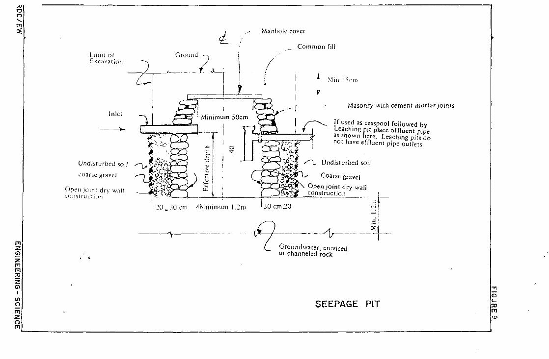
Limit of Excavation
<L Manhole cover
Common fill Ground
Min 15cm
Undisturbed soil
coarse grave
Open joint dry wall cons! ruction
Masonry with cement mortar joints
fused as cesspool followed by Leaching pit place offluent pipe as shown here. Leaching pits do not have effluent pipe outlets
S~\, Undisturbed soil
Coarse gravel
Open joint dry wall
20.30 cm ^Minimum 1.2m ^Ocnv^O E
CM I" -v . . . - ^ — J ! j _
Groundwater, creviced or channeled rock
SEEPAGE PIT o c m
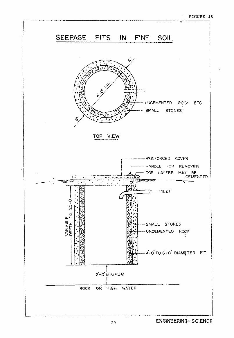
FIGURE 1
SEEPAGE PITS IN FINE SOIL
UNCEMENTED ROCK ETC.
SMALL STONES
TOP VIEW
-^srf.' f
o i
o o
OQ T
cro.
0°
SI
5JM
I 3(
' - /A
•REINFORCED COVER
HANDLE FOR REMOVING
^fifa TOP LAYERS MAY BE
CEMENTED ZSAf/iSW —x _
INLET
2 - 0 MINIMUM
SMALL STONES
UNCEMENTED ROpK
4 - 0 TO 6 - 0 DIAMfTER PIT
ROCK OR HIGH WATER
21 ENGINEERING-SCIENCE

FIGURE 11
RDC/EW
MIN MAX
I-
TOP SOU FOB SWUNG
EARTH BACKFILL
U N T R E A T E D BUILDING PAPER
OR STRAW
J. i 2 " M I N
. 0 a o 0 .
° ' o . '•([«!« j / j PIP
1 1 , * ' I «
MIN
1
DISTRIBUTOR
E • o
. o n
. 0 0 o i •
0
0 o ^ Q 0 ° Q « e Q * o
P E R F O R A T I O N
A e SLOPE 1/16
JOINT
X L .
d o «
- H 3 2 - PER FT.
<» a * f I *
GROUNO W A T E R . BEOROCK.
OR IMPERVIOUS LAYER
SPACING OF \ C R U S H E O STONE
A 8 S 0 R P T I O N T R E N C H W A S H E D GRAVEL
« O.C - ' * ' TO 1 V>"
C R O S S SECTIONAL VIEW
—/IT. ^ r. rr. Tyrr. T/T. 7T
L O N C I T U D I N A L VIEW
• 0 • •>
' o o o o
U N T R E A T E D BUILDING PAPER OR S T R A W
• 0 o ~ T ~ 0 0 .
o n n o o n o n o o o
» fro
, . o . . - * - . . , . • •
Q n n n o n n n n n o n o p r , o o
0 « d
Q n n , t
y * o u O c
u 0 * O 0 0 o
SLOPE T R E N C H B O T T O M t / 1 6 " — 1/32" PER FT
TRENCHES FOR ABSORPTION FIELD
S t t p a g i b«d l y i t t m •i'l '>' & t « p « g i o « a » y i l t m •>!'/ .'/i 11 , \
1— * " ~""*—\ \v w v U n t i t i i t d bui ld ing p i p « r \ . < ? ! r '
4* M i n i m u m l u l t i b l * to l l
^ ' ^ - ^ • ' - O * - ~ ~ - l 2 ~ ''""7, ' * = " ~ < l j : ^ - ' L lml l lng xont *
A • • • p a g t b«d m t k t i m o r t «f f lc l«nl u f l 0\ lh« spftC* a v i l l i b l * for sf f luvnl d l i p o t a l on m t m i l l lo
SEEPAGE PIT
ENGINEERING-SCIENCE
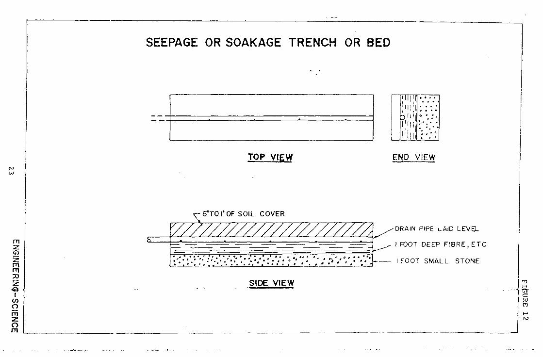
SEEPAGE OR SOAKAGE TRENCH OR BED
TOP VIEW
" I I I 1 ! | l i ! ! l
I 'M!,
I ' I I I !
• • • 4
* m • • r • • «
° '.: • * *. * •
END VIEW
^-6fTOrOF SOIL COVER
h
'//////////////////////, /»»"™ - L-e-A A A * A
• _ ^ ^ - 1 FOOT DEEP FIBRE, ETC
« 1 r O O T ^ M A I 1 C T D N F
SIDE VIEW

SPECIAL PRECAUTIONS
1. Do not place any part of a seepage pit below normal
high ground water level.
2. *:;eep bottom at least two feet above rock formations.
This is especially important in limestone type preas.
(See following illustrations of sand filter bedf
between the seepage system bottom and limestone)
3. Try to avoid installing systems where percolation rate
exceeds 60 minutes per inch.
4. Avoid installation of trenches in rainy weather, because
wet conditions tend to "smear" soils so they arf less
absorptive.
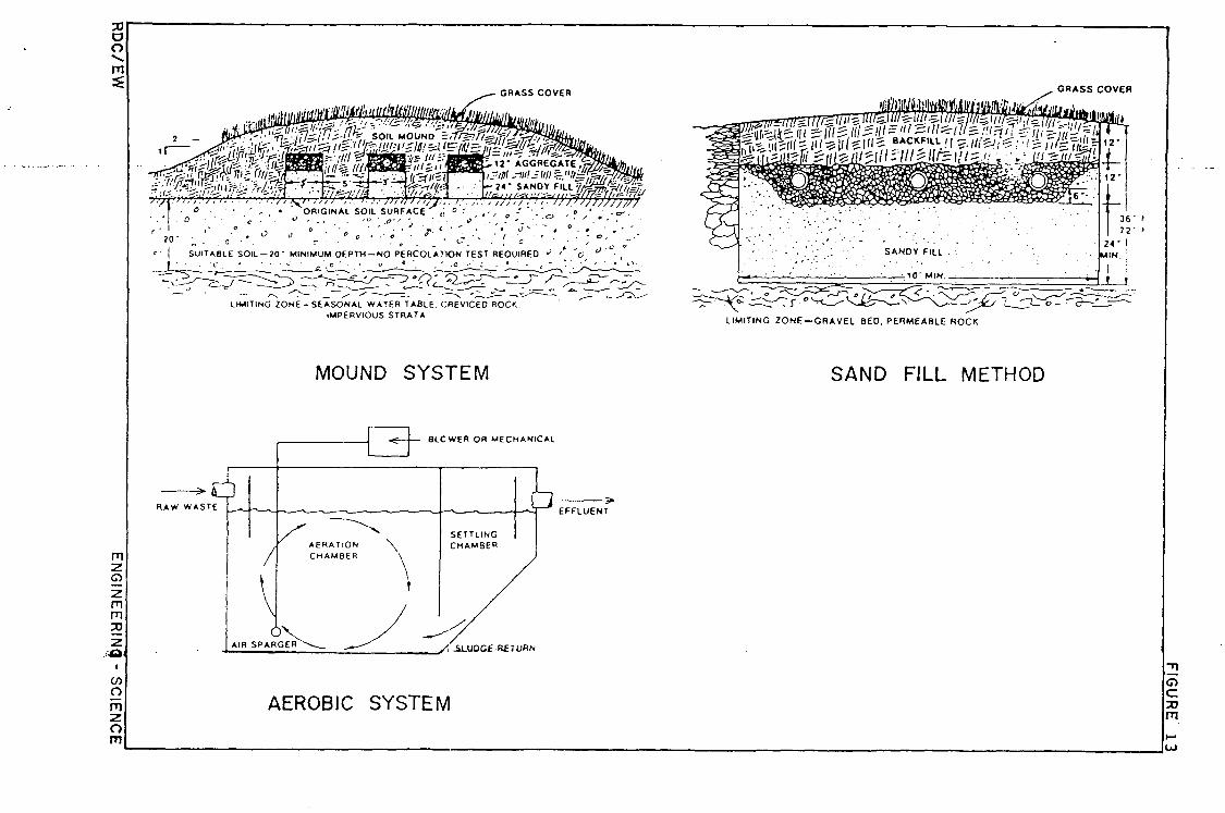
SPECIAL TYPE SOIL ABSORPTION SYSTEMS
SHALLOW DEPTH SOIL OVER POROUS LIMESTONE OR GROUNDWATER
In all cases effort should be made to be sure sewage or
drainage from pour-flush latrine vaults must seep through at
least 20 to 24 inches of soil of fine sand before entering the
limestone. See following sketch.
If necessary, elevate toilet to enable placing the $and
above the limestone or water table and below the drain. Elevated
systems should be considered where seasonal high groundwater
table would be less than two feet below the bottom of thp
disposal system.
intemationa.3 V::"ir^.z CJfCuO for •Ccrt.:..-:-.ttv '• -"Hlv
24

OTHER DESIGN FACTORS
1. Grade of Bed and Lines - Trench bottom or beds should be
' approximately level.
2. Depth of Gravel - The MSTP requirement of a total of
12 inches of gravel for a conventional bed, with 6 inches
below the distributing pipe appears to be reasonable.
3. Depth of Bed - An 18 or 20 inch deep bed and 6 to 8 inch
deep soil cover is a practical minimum.
4. S-*-cing of Distribution Lines - Spacing for distribution I*-
lines in seepage beds to be no more than G feet apart
and 3 feet from the bed's side walls is good practice
5. Special Construction Precautions - Since it is convenient
to excavate and fill beds by use of tractors, there is
temptation to drive over the bed bottom. This cap cause
severe compaction and loss of permeability. Beds should
not normally be constructed in rainy weather because of
the effects of rain and ponding on the permeability of
some soils (also somewhat true of trench construcpion).
25

SUMMARY OF SYSTEM DESIGN
Seepage Trenches
Trenches are usually 18 to 36 inches wide and 18 to 36
inches deep. They have a 3 to 6 inch layer of stones (1 to 2
inches in diameter) at the bottom.
They are laid nearly level. The perforated or open-pointed
drain pipe are laid with an even grade, upon the rock (or a board
embedded in the rock). The pipe is covered to a depth of 2
inches with rock. The rock is covered with straw and 6 inches
or more of soil.
Seepage Beds
Seepage beds are dug two to three feet deep and have the
same depth of gravel (stone) as the trenches, but covering the
whole bed bottom. The drain pipes are laid level, 6 feet apart,
and covered with stones, straw and earth, as for seepage trenches.
Seepage Pits
These are usually 4 to 6 feet in diameter. The bottpm is
not covered with stones. The side walls are uncemented stones,
brick or cement blocks. Sometimes, where soil is not as coarse
as sand, there is a 6-inch space between the side wall and the
soil whicht is filled with will - size stones (1/2 to 1 ineh
diameter) \See Figure 1.1).
2 6

ABSORPTION SYSTEM
Absorption systems, (disposal trenches), are preferred
where the groundwater level is high (encounter water when hole
is few to fifteen feet deep); where subsoil is impervious^
overlain by previous formation; or, where there is seamy lime
stone causing concern about contamination of wells or springs.
The absorption field subsurface tile or drain system
is usuallly made by placing open-jointed drain tile, or special
perforated pipe, in a bed of gravel in a trench or bed. The
trench or bed is usually 24 inches to 30 inches deep; dra .n
lines are placed on a 6 inch deep bed of gravel and then
covered with gravel to a depth of a few inches; the trenches
are nearly level. The gravel is covered with straw and then
backfilled with earth. The trenches are usually from 18 J.nches
to 36 inches wide and on a flat grade (fall of one inch to
three inches per 100 feet) (See Figures 9 and 10).
27

Aerobic Systems -There are many aerobic systems which
utilize the basic principles of the "activated sludge process".
This means that the sewage must be continually mixed with fine
air bubbles for 6 or more hours;the sewage must then pass slowly
through another tank so particles of organic material (sludge)
can settle out. A large part of that settled sludge is circulated
to the inlet of the "aeration tank". This whole process must
be operated most of the time,each day,to be successful.
Excess sludge must be removed periodically, usually drained
to an artificially built sand bed,where it dries.
The system,when properly operated, does produce a relatively
clear and stable (non-odorous) liquid,which is relatively free
of pathogens (but it usually must be chlorinated if discharged
into streams or near shellfish beds of the sea).
DISADVANTAGES OF ACTIVATED SLUDGE SYSTEMS
..This consultant has visited many activated sludge and
similar "c -.ended aeration-packaged treatment plants" in
developing countries. A high percentage of such systems were
observed to function little better than a septic tank. The
main problems were:
1. High cost for electrical energy,so blowers or
aerators were turned off most of the day.
2. Mechanical devices were not maintained and repair
parts were not readily available.
3. Communities could not afford to hire trained operators
or to provide the necessary manpower for maintenance,
testing, and operation.
28
CRASS COVER
^inn'i,'t'y;fi.-. • , ••• .-••;'••• ' O " :m r/.'.^.v JJ,/}7,VJ;::r •;r/7/;\Fr> irf);•*'/} J •• ° • • ' - • ' ORIGINAL SOIL SURFACE ,: ° ' . • , „ - " ' ' ° '
• . ' I • 0 • • ' •• c • ' • •> • . . . ' " .*-•< -. ' * . . ° - . ° r ' ' <" ° i • . ' » ' • ' „ - ' ' ' • ' ^ " ' ~ ' " • •
2°" „ • =' : * . " r : • " ' • ' • . " . . - c ; - : { \ s ' '• ! SUITABLE SOIL —20" MINIMUM DEPTH —NO PERCOLATION TEST REOUIREO °
' • u . . « • ' . o ' ' : • . " • - , -
LIMITING ZONE-SEASONAL WATER TABLE. CREVICED ROCK. IMPERVIOUS STRATA
MOUND SYSTEM
. < BLCWER OR MECHANICAL
/ , -SL.U0C£ Rf 7URN
AEROBIC SYSTEM
GRASS COVER
LIMITING ZONE —GRAVEL BED. PERMEABLE ROCK
SAND FILL METHOD
U )

CONVENTIONAL PUBLIC SEWERS AND SEWAGE DISPOSAL
Public sewers and sewage disposal are the .most satisfactory
means of excreta and wastewater disposal for built-up, urban type
areas. Such sewers must be built with sufficient slope or grade
to transportfaecaJ solids and similar material. The quantity of
wastewater must be great enough to help flush the material to the
disposal site. Manholes are provided each few hundred meters to
provide access for cleaning and inspection.
In flat country,as in the Region, it is necessary to lay sewers
at grades greater than land surface grades. That results in deep
trenches, often into groundwater or difficult-to-excavate limestone.
It also requires sewage pumps.
SPECIAL SEWERS - Even in developed countries (U.S.A.fpr instance)
special, lower-cost sewers are being used in special circumstance.
One type uses smaller diameter plastic pipe laid on relatively flat
grades. This is possible where all wastewater (sewage) has passed
though a sedimentation process such as a septic tank , aqua privy or
settling compartment of a pour-flush latrine.
Larger systems, such as from a group of living units (apartments)
hotels and certain industrial and commercial occupancies can have a
simple sump pump to discharqe their wastewater to such sewers. That
helps produce enough flow to flush the small-diameter lines. If
necessary, flushing connections can be provided at the up-stream end
of each line. There, portable tanks with pumps can be used to flush
the lines, when necessary.
, PUBLIC SEWAGE DISPOSAL
SEPTIC r,;ANKS - Septic tanks do not produce a suitably treated
wastewater, but such liquid has an unpleasant odor, causes nuisances
and kills fish in streams or ditches, and contains pathogens
(disease microorganisms).
Also, the large septic tanks needed for public sewerage systems
cannot normally be properly cleaned. 30

STABILIZATION PONDS
For most small to medium-sized communities, especially in
warm climates,the most simple,inexpensive and comparatively
trouble-free systems are "stabilization ponds" or "oxidation
ponds". These are used in both developed and developing countries.
Principles
Sewage contains nitrates, phosphates, potassium and
other "plant nutrients". When a relatively shallow pond of sewage
is exposed to sunlight a small plant growth (plankton) becomes
suspended ; .voughout the liquid. This is a green ;.-• iant. The
green material (chlorophyl) helps produce a good utilization
of plan nutrients in the pond. Carbon dioxide, produced by
natural transformation of organic carbon, is utilized by
chlorophyl-containing small particles of plants, "algae", f.o
form cells of more algae. The oxygen from the carbon dioxide
(C0„) is released to the water where it becomes "dissolved
oxygen" (D.O.).
The D.O. accomplishes the same purpose in the stabilization
pond as is accomplished by mixing air with sewage in the activa
ted sludge process. In other words, in nitrogen-compound-contai-
ning water, there is a growth of microorganisms (protozoa) which
convert organic forms of nitrogen (proteins, amino acids and
ammonia) to inorganic nitrates, thereby stabilizing the organic
compounds. The action produces up to 90% or more reductiop
in organic pollutants measured by a process which determines
how much dissolved oxygen would be required to stabilize a
liter of water. This unit is called biochemical oxygen demand.
(B.O.D.).
2 1

r
X
I
~K-SECURE FENCE
3T
K
mit»tm&ti:&&8rt\i
i i
/ »
80TTOM
NEARLY
WATER- TIGHT
'?g&82cB£A
V^ R I P - R A P INSIOC —
^ ? f f l ? f f M f f l g W ^ "
suvvuu
LENGHT ABOUT
rvicE WIDTH
Tfee^flg£
PLAN VIEW STABILIZATION POND DESIGN
^ S 2 2 E £ 2 3 E 2 35 WATER L E V E L

Pathogen Removal
Studies in India and elsewhere have shown that when gewage
passes through a suitably designed pond system, consisting of
at least three ponds, flowing from one to the next, (serial
arrangement) over 99% of the coliform and most of the pathogens,
including virus and intestinal parasites, are removed.
A typical arrangement and design of a stabilization pond
system is shown in Figure 8.
Additional Advantages
Costs are low where land is level, soil is suitable ajid
land costs are not too high.
Maintenance is minimal. Side walls are kept free of weeds
or are paved.
Sludge removal is only infrequently necessary.
The effluent of ponds receiving non-brackish water ca.n be
used for irrigating. Also, pond effluent which contains algae
is good for raising fish.
Where used for private development, which will eventually
be connected with a community sewerage system, the ponds can
then be filled in and the land is used for development.
CONSERVANCY SYSTEMS
Where Required - Where housing and business establishments
are built so closely together that there is no room for pour-
flush toilets or septic tank systems and where sewers canqot be
built because of cost and other factors, conservancy systems do
fill a necessary health need.
33

Special Features - ideally, conservancy units are so built
that the pail is in a closed chamber which is accessible to the
conservancy worker from outside of the building. The base or
floor of the space where the pail is kept should be of smooth
masonry or plastic and should drain to a small soakage ho^e.
Pail System - Systems where conservancy workers are required
to clean householder's pails expose the workers to addtiorjal
fecal contact and undesirable labor. The preferable system is
to have pails which can "nest" together so a considerably
number of empty pails can be carried in a small space. Tfyen
clean, empty pails and soiled, used and emptied pails can be
carried on the pushcart. Collected pails can be emptied into
larger containers on the pushcart.
Within reasonable distances from the houses and shops
which are served, there should be properly designed vehicles
or subsurface storage tanks into which the filled buckets can
be emptied. These need not necessarily be washed until tfye
end of the working day.
If subsurface storage is provided, a vacuum tanker
;provides an ideal method of emptying those tanks and for
transporting and dumping the material in a suitable disposal
site.
At that site there should be a bucket-washing device
which is equipped with a pump, nozzles and enclosed chambers to
wash buckets with a minimum of human contact. (This Consultant
noted such systems at Serembran, Malaysia). Wastewater frc m the
washer should flow through a large septic tank to a subsurface
absorption system. The wash water could be pumped from a-
34
brackish v."ater well or the sea.
Disposal Site - The final disposal site should be several
! hundred meters from occupied land. The soil should be reasonably
porous to seep away the liquid. It should be several hundred
meters from any potable water supply well and should have at
least 5 feet of soil above the highest groundwater level or
limistone formation.
Educational and Health Programs - Conservancy workers should
be given special preventive medical treatement. This should
include treatment to help prevent typhoid, cholera and hepatitis
Type A.
They should also be trained and supervised to minimize
contact with excreta and to practice personal hygiene. Ideally,
they would have, at their headquarters, shower and washing
facilities.
35

APPENDIX I
UNDERGROUND TRAVEL OF CONTAMINATION
There are several reports on tests which were made to learn how
far bacteriological contamination will travel in various soil
and rock formations. The findings were:-
1. DIRECTION OF TRAVEL
If the-direction of flow of the groundwater is known or
can be discovered, then it is known that bacteriological
contamination will flow j.n the same direction as the
water.
2. FILTRATION IN SOILS
Scientists like Hazen and others found, from tests,
decades ago:
a. Under a privy vault in non - saturated, fine (loam)
soil, no coliform organisms traveled more th n 3 feet
vertically downward.
b. In sandy soils with shallow groundwater, contamination
from a test latrine was found to concentrate in the
top few feet of groundwater. This led to the principal
of some codes which advise that well casing should be
water - tight for several feet below the lowest level
in the well, during pumping.
c. Underground travel.
In a test program at the University of California^
contaminated wastewater was injected into a layer of
sand mixed with small stones. The maximum distance the
contamination traveled was 100 feet. Even when the test
continued for many months, the distance of travel did
36

not increase.
d. Path of travel in sand.
This Consultant made extensive tests in a rather
coarse sandy soil. Septic tank liquid was applied
for months. Underground collection systems were
installed ("Lysimeters".) Test holes were dug.
The test showed that the septic tank liquid did
not travel straight down but spread out into a
20 foot diameter circle. Vertical travel of 8
feet downward removed all coliform, even in this
coarse sand.
CONCLUSIONS - FOR GRANULAR SOILS
In soils ranging from coarse sand to clay the travel of
bacteriological contamination is directly related to,
a. Direction of flow of groundwater. i
b. Depth of well casing below the water table surface.
c. Size of soil particles, with fine soil producing very
high purification in a few feet of travel.
d. Contamination introduced directly into the water table
flows much farther than contamination introduced into
non - saturated soil. *
CONTAMINATION TRAVEL IN ROCK
Where a water supply is obtained from crevices, channels
and other openings in rock, especially limestone, the
bacteriological contamination will flow in the same direction
as the groundwater and will travel for long distances.
There is no filtration, for purification, so the distance
contamination will travel depends upon the rate of flow,
much the same as travel of contamination in a stream.
37

The distance can be several miles.
5. SOIL AND GROUNDWATER INVESTIGATIONS
a. Test holes to determine soil, rock and groundwater
conditions.
b. Where necessary, percolation tests (To later have
field exercises on conducting observations of test
ho*- s and percolation tests).
38

APPENDIX II
VOLUMES OF EXCRETA FROM
POUR-FLUSH SYSTEMS
The WHO publication, "Excreta Disposal for Rural Areas and
Small Communities" provides data on quantities of human excreta.
For example, for privies where water is not used for
flushing or personal hygiene, the following are given:
Type Toilet Volume added per year
Pit Privy - liquid (urine) 1.5 cu. ff. per year soaks away ) Pit Privy - no seepage 19.5 cu. ff. per year.
AQUA PRIVY
(Would be same for pour-flush, water - seal latrine having
a water - tight vault).
Volume =4.5 = 1 imp. gal/day
(2 gal/day/capita recommended for design).
Volume, then = 365 imp.gal/person/year =
438 gal/capita/year =
58 c.f./capita/year.
If vault was water - tight and as large as septic tank
3' 'wide; 9' long, 4•deep = 100 0 gal = 133 c.l.
If used by family of 6 persons.
Totals quantity per year = 58 x 6 = 348 c.f./year
The tank would fill 348 f 133 = 2.6 times per year.
However, the WHO publication suggests for design (to make
allowance for 3 unusual circumstances, assume twice as much waste i .
per capita*per year. That would mean that some tanks would have
to be pumped 2.6x2=5,2 times per year or about every two months.
39

^ter^-^Sealed i§£rine with soak - away; vault.
In this case the volume would be only the quantity of
feces per year, or about 1.5 c.f/capita/year.
For the family of 6 the volume of feces would be
6 x 1.5 = 9 c.f/year.
Assume the vault was 31 wide; 5' long and 4' deep or
500 gallons (66 c.f.).
This would need to be emptied 66 f 9 = once in 7 years.
The above data should be checked in Jaffna by experienced
observers, but do provide evidence to show the importance of
trying to»provide vaults from which the liquid will drain.
The data also show that if there is no provision for
seepage of liquids into the soil, there would be a large pumping,
hauling and disposal problem. That is why it appears reasonable
to provide small - diameter plastic drain pipes to dispose of
liquids from pour-flush latrine vaults. Then the vaults would
not have to be pumped more often than once in several years.
SPECIAL_STUDIES_OF_SOIL_AND_GEOLOGY
Both from the question of obtaining well water and disposing
of waste water it is important to have good knowledge of local
geology and hydrogeology. It is also important to accept the
advise of the Regional Water Resources Board Engineer who
advised at the Introductory Training Program that rock forma
tions, soil conditions and water quantity can be very ununiform
- can change much within short distances. However, it is also
good to have good knowledge of those conditions which have been
found to remain uniform throughout whole areas.
40

TEST_HOLES
There are several types of test holes. This Manual des
cribes the holes for making percolation tests. In addition
it is wise to make additional tests to:
1. Learn depth and type of soil below the bottom of the
proposed seepage system. It is into this formation that
the water must seep. This tells if there is the necessary
two foot depth of soil above limestone.
2. Observe soil colors and formations and otherwise note the
highest level of the water table.
3. Examine the soil to determine if it is of a type suitable
for seepage of waste water.
QTHEI^OBSERVATIONS
Always try to make sure a new excreta disposal system
will be so located as to not contaminate any nearly well,
including those on neighbour's property.
41