basic requirements for preliminary conceptual design of
TRANSCRIPT

KAERI/TR-3673 /2008
기술보고서
Basic Requirements for Preliminary Conceptual
Design of the Korea Advanced Pyroprocess
Facility (KAPF)
2008. 12
Korea Atomic Energy Research Institute

KAERI/TR-3673 /2008
제 출 문
한국원자력연구원장 귀하 본 보고서를 2008년도 “ 핵비확산성 핵연료주기기술 한미협력증진” 과제의 기술보고서로 제출합니다.
2008. 12
주 저 자 : 이 호 희 공 저 자 : 고 원 일
송 대 용 장 홍 래
권 은 하 이 정 원

- 1 -
CONTENTS
1.0 INTRODUCTION .......................................................................................... - 4 - 1.1 BACKGROUND .......................................................................................................... - 4 -
1.2 APPROACH TO THE WORK ...................................................................................... - 5 -
2.0 OVERVIEW OF THE KAPF FUNCTIONS............................................... - 8 - 2.1 KAPF DESCRIPTION................................................................................................ - 8 -
2.1.1 Hot Cell Lines ...................................................................................................- 8 -
2.1.2 Balance of Plant ................................................................................................- 9 -
2.1.3 Support Facilities...............................................................................................- 9 -
2.2 PRIMARY FACILITY FUNCTIONS........................................................................... - 10 -
2.2.1 Materials Receipt and Storage.........................................................................- 10 -
2.2.2 Head-end Process ................................................................................................ 14
2.2.3 Pyroprocess ......................................................................................................... 15
2.2.4 Pyroprocess Material Treatment, Handling and Storage..................................... 19
2.2.5 SFR Fuel fabrication ........................................................................................... 19
2.2.6 Waste Treatment, Handling and Storage............................................................ 19
2.2.7 Shipping .............................................................................................................. 23
2.2.8 Safeguards and Security ...................................................................................... 23
2.2.9 Instrument & Control (I&C) Infrastructure......................................................... 24
2.2.10 Safety................................................................................................................. 24
2.2.11 Quality Assurance ............................................................................................. 24
3.0 KAPF PERFORMANCE REQUIREMENTS................................................25
3.1 OVERALL PERFORMANCE REQUIREMENTS.............................................................. 25
3.1.1 Plant Capacity ..................................................................................................... 25
3.1.2 Plant Availability................................................................................................. 25
3.1.3 Plant Design Life................................................................................................. 26
3.1.4 Plant Location..................................................................................................... 26
3.1.5 Reference PWR Spent Fuel................................................................................. 26
3.1.6 Reference SFR Fresh Fuel................................................................................... 29
3.1.7 Reference Transport Cask for PWR Spent Fuel.................................................. 31
3.1.8 Reference Transport Cask for Fresh SFR Fuel.................................................... 33
3.1.9 PWR Spent Fuel Lag Storage.............................................................................. 33

- 2 -
3.1.10 SFR Fuel Storage .............................................................................................. 33
3.1.11 Waste Storage.................................................................................................... 33
3.2 GENERAL REQUIREMENTS........................................................................................ 33
3.2.1 Design Approches and Goles .............................................................................. 34
3.2.2 Applicable Codes, Standards and Regulations.................................................... 35
3.2.3 SAFETY CONSIDERATIONS .......................................................................... 35
3.2.4 Facility................................................................................................................. 35
3.2.5 Equipment ........................................................................................................... 36
3.2.6 Instrumentation and Control:............................................................................... 36
3.3 MATERIALS RECEIPT AND STORAGE REQUIREMENTS ........................................... 37
3.4 HEAD END PROCESSING............................................................................................ 38
3.4.1 Disassembly and Batching .................................................................................. 38
3.4.2 Mechanical Treatment......................................................................................... 38
3.4.3 Thermal Treatment .............................................................................................. 38
3.3.4 Product Clarification ........................................................................................... 38
3.3.5 Waste Treatment and Handling........................................................................... 39
3.3.6 Process Off-Gas Control and Treatment ............................................................. 39
3.5 PYROPROCESSING...................................................................................................... 39
3.6 PROCESSED MATERIAL HANDLING AND STORAGE REQUIREMENTS..................... 40
3.7 FUEL FEED MATERIAL AND SCRAP CONDITIONING REQUIREMENTS ................... 40
3.8 FUEL FABRICATION REQUIREMENTS....................................................................... 41
3.9 WASTE TREATMENT, HANDLING AND STORAGE REQUIREMENTS ........................ 42
3.10 SHIPPING REQUIREMENTS ...................................................................................... 43
3.11 FACILITY SUPPORT REQUIREMENTS...................................................................... 43
3.12 SAFEGUARDS AND SECURITY .................................................................................. 45
3.13 INSTRUMENTATION AND CONTROL (I&C)............................................................. 46
3.14 FACILITY DECONTAMINATION AND DECOMMISSION........................................... 47
3.15 QUALITY ASSURANCE.............................................................................................. 47
4.0 COST ESTIMATE............................................................................................48
4.1 GENERAL ASSUMPTIONS........................................................................................... 48
4.2 SCENARIO................................................................................................................... 48
4.3 METHODS OF COST EVALUATION ............................................................................ 48
4.4 CONCEPTUAL DESIGN PROVISIONS FOR INDIRECT COSTS .................................... 49
4.4.1 Conceptual/Final Design and Inspection............................................................. 49

- 3 -
4.4.2 Licenses............................................................................................................... 49
4.4.3 Permits................................................................................................................. 49
4.4.4 Taxes and Insurance ............................................................................................ 50
4.4.5 General and Administrative /Engineering and Construction Management
Costs ................................................................................................................... 50
4.4.6 Research and Development Costs ....................................................................... 50
4.4.7 Startup and Testing.............................................................................................. 50
4.4.8 Initial Training..................................................................................................... 51
4.4.9 Decontamination and Decommissioning............................................................. 51

- 4 -
1.0 Introduction 1.1 Background
Nuclear energy is the most powerful method to secure energy with the reduction of CO2
emission to prevent global warming. Since the first commercial operation of Kori unit 1 in
1978, the nuclear power program in Korea has steadily grown. As of December 2007, twenty
nuclear power reactors are in operation with a generating capacity of about 18,000 MWe,
supplying approximately 40 percent of the total electricity produced in Korea. According to
“The 3rd Basic Plan of Electricity Demand and Supply in Korea” announced in 2006 by the
Ministry of Knowledge and Economy (MKE), eight new nuclear power units will be
constructed by 2020, making the total number of reactors 28. However the generation of
electricity by nuclear power reactors also has caused a drastic increase of spent fuel which is
an inevitable by-product of nuclear energy. At the end of 2007, the cumulative amount of
spent fuel generated in Korea was about 9,400 tHM and it is expected to jump to about
30,000 tHM by 2030. The research on spent fuel management focuses on the maximization of
the disposal efficiency by a volume reduction, the improvement of the environmental
friendliness by the partitioning and transmutation of the long lived nuclides, and the recycling
of the spent fuel for an efficient utilization of the uranium source.
Korea Atomic Energy Research Institute (KAERI) has been developing technologies for
pyroprocessing for spent nuclear fuels. This study is part of a long term R&D program in
Korea to develop an advanced nuclear reactor power generation and recycle system that has
the potential to meet and exceed the proliferation resistance, waste minimization, resource
minimization, safety and economic goals of approved Korean Government energy policy, as
well as the Generation IV International Forum (GIF) program. The preliminary milestones
established by KAERI for this program call for a decision by the Korean Government to
proceed from the Engineering Mockup development phase, to the Design and Construction of
the Engineering Scale Pyroprocessing Facility Phase. To support this decision, KAERI
requires that an independent estimate be made of the conceptual design and cost for
construction and operation of a “Korea Advanced Pyroprocessing Facility”, or KAPF.
Gamma, having previously performed a study for the KAERI DUPIC facility in 1996, has
been requested to propose a similar study for KAPF.

- 5 -
1.2 Approach to the Work
This section describes the approach to the work of producing a conceptual design and
evaluating a cost estimate of a commercial scale KAPF (Korea Advanced Pyroprocess
Facility) that will extract fuel material from spent PWR fuel assemblies, perform
pyro-process, and fabricate the metal fuel assemblies for use in SFR reactors.
Assessment of a new technology is always a difficult exercise. Given that the
pyroprocessing technology has never been demonstrated beyond laboratory scale, there is no
direct approach that can be used to determine the economic feasibility of the KAPF process
on a commercial scale with complete certainty. However, a reasonable estimate can be
obtained by making use of the information already available from other technological
systems with attributes similar to the KAPF. In this regard, Gamma Engineering is tasked to
provide a preliminary conceptual design and cost data of the pyroprocessing facility,
including the evaluation of the technology. KAERI will provide Gamma Engineering with the
necessary information as well as technical requirements for this study. Gamma Engineering
will also use its knowledge of applicable regulations and standards in developing a
conceptual design for a commercial-scale KAPF facility with an assumption that it would be
built in the U.S.
A functional flow diagram and material balance sheet were developed based on the
technical requirements, and the configuration of the KAPF facility will be developed by
Gamma Engineering which will cover process component arrangement, hot cell layout,
building design, and interface with the plant boundary, etc.
The cost evaluation relies on a standard cost estimating methodology used for large scale
facility construction and operation, and will be performed as the conceptual design is
developed. Input data for the capital and operating costs will be identified and determined by
Gamma Engineering based on the established industrial practices and quotes from equipment
vendors. A sensitivity analysis of the cost results will then be performed.
The results of this work is subject to review by ANL/ORNL with due focus on remote
systems operation and maintenance. A schematic process for KAPF cost evaluation and
overall methodology for the cost evaluation are shown in Figure 1.1 and 1.2, respectively.

- 6 -
Figure 1.1. Schematic Process for KAPF Cost Evaluation.
Requirements
Reference Process Model
Facility Design
Process Flow Equipment Hot Cell Layout Building Auxiliary Systems Others
Evaluation of Capital Costs and Operating Costs
Life-cycle Cost & Unit Cost Analysis
Refinement Calculation of KAPF Facility Cost and Its Sensitivity Analysis
Anchor Facility Other Reference
Material /Labor Cost
ANL/ORNL Review(optional)
KAERI/Gamma
Gamma /KAERI
Gamma /KAERI
Gamma /KAERI
KAERI/ Gamma
ANL/ORNL
Levelized Unit Cost Model
Evaluation of Capital Costsand Operating Costs
Life-cycle Cost & Unit Cost Analysis
KAERI
KAERI
KAERI
GAMMA/KAERI

- 7 -
Requirements
↓
Conceptual Design
∘ Functional Flowsheet
∘ Material Balance
∘ Process Components
∘ Facility Configuration
- Components Arrangement - Hot Cell Layout - Building Design - Interface with Plant Boundary
∘ Trade-off Study
↓
Cost Evaluation
∘ Establish Methodology
∘ Capital Costs
∘ Operating Costs
∘ Unit Cost
- Life Cycle Model - Financial Factors - Levelized Costs
∘ Sensitivity Analysis
↓
Final Report
Figure 1.2. Overall Methodology for Cost Evaluation.

- 8 -
2.0 Overview of the KAPF Functions 2.1 KAPF Description
KAPF (Korea Advanced Pyroprocess Facility) is an integrated pyroprocessing facility to
process the spent oxide fuels discharged from PWRs and fabricate metallic fuels containing
TRU (transuranic) for future SFRs (Sodium Cooled Fast Reactor). The KAPF is a centralized
facility for spent PWR fuel treatment, and expanded on module basis as needed. The KAPF
shall be a complete fuel recycle plant that covers all functions and equipment for processing
spent PWR fuel and converting it to SFR metal fuel. The non-fuel components required by
the SFR fuel bundle will be fabricated by off-site facilities and shipped to the KAPF site. The
facility will contain all support systems (material handling/storage, waste processing,
packaging, storage, and utilities) necessary for KAPF operation and maintenance. The KAPF
shall have provisions for emergency power generation and related equipment for sustaining
essential plant operation and safe plant shutdown procedures. The KAPF shall be designed,
constructed and operated with emphasis on protection of public and worker safety and the
environment.
KAPF covers overall facility design from a functional point of view. Global categories of
the facility design, by usual practice, can be broken down into:
(1) Hot-cell lines
(2) Balance of plant
(3) Support systems
2.1.1 Hot Cell Lines
The core of the KAPF is the main cell system in which major functional operations of
nuclear material flow are accommodated. Other cells are for subsidiary works, associated
with the main operations. Those hot-cell lines are a shielded concrete structure with adequate
spaces and appropriate functional equipment systems for in-cell operations and maintenance.
An important portion of the hot-cell line operations, apart from the nuclear material flow, is
assumed by the decontamination and maintenance (D&M) system. Remote decontamination
and maintenance are generally applied to most in-cell operations. This typically involves
replacement or repair of equipment or components (including remote maintenance systems
themselves) that can be done effectively by the D&M (decontamination and maintenance)
system. Supplementary to the remote D&M, the contact maintenance system, which would

- 9 -
not require extensive shielding, covers the tail-end maintenance function. The D&M systems
will be accompanied by suitable ship-out systems to dispose of waste packages. In-cell
viewing and illumination, remote maintenance systems, through-the-wall material transfer
systems, and various safety systems embedded are the basic features provided with the hot-
cell lines.
2.1.2 Balance of Plant
The balance of the KAPF constitutes the periphery around the hot-cell lines and the
interface with support facilities or outside boundaries. This area requires substantial space to
accommodate various front- and tail-end functions of the hot-cell lines operation. A
significant portion of potential radiation dose rates to workers is also attributed to these areas.
Automation and robotic assistance could replace some manual work to reduce such dose rates.
Various systems of equipment and instrumentation are installed around the hot-cell lines for
equipment operation and safety monitoring and control. Some of these are in direct
connection with in-cell equipment, but many of them are indirectly related systems, such as
measurement and control systems to support the hot cell operation.
The waste-handling system is an important part of the balance of the plant. There are
two categories of wastes. Operational wastes are collected through the hot-cell lines into a
buffer storage area, which is in fact shielded cell(s) categorized in the preceding subsection.
Less radioactive wastes are handled in a separate area with less extensive shielding. The
D&M wastes (mostly unusable equipment or components) are handled in the hot or suspect
repair area previously called the contact maintenance area. Packaging of equipment wastes is
also done in this area for shipping or for buffer storage. Systems for shipping in or out of
transportation casks for spent fuels or waste packages (including transportation vehicles and
the inspection and washing area) also belong to the balance of the plant.
2.1.3 Support Facilities
The KAPF will include the necessary support infrastructure and balance of plant support
features to accomplish mission objectives. This function includes facility access, control
center, testing, remote cold mock-up, analytical services, instrumentation and control, storage
buildings, training and office facilities, utilities, integration of operations personnel, cold
chemical makeup, confinement control, effluent management, support for operational

- 10 -
readiness reviews, National Environmental Policy Act (NEPA) support, environmental
permitting, and other programmatic needs.
2.2 Primary Facility Functions
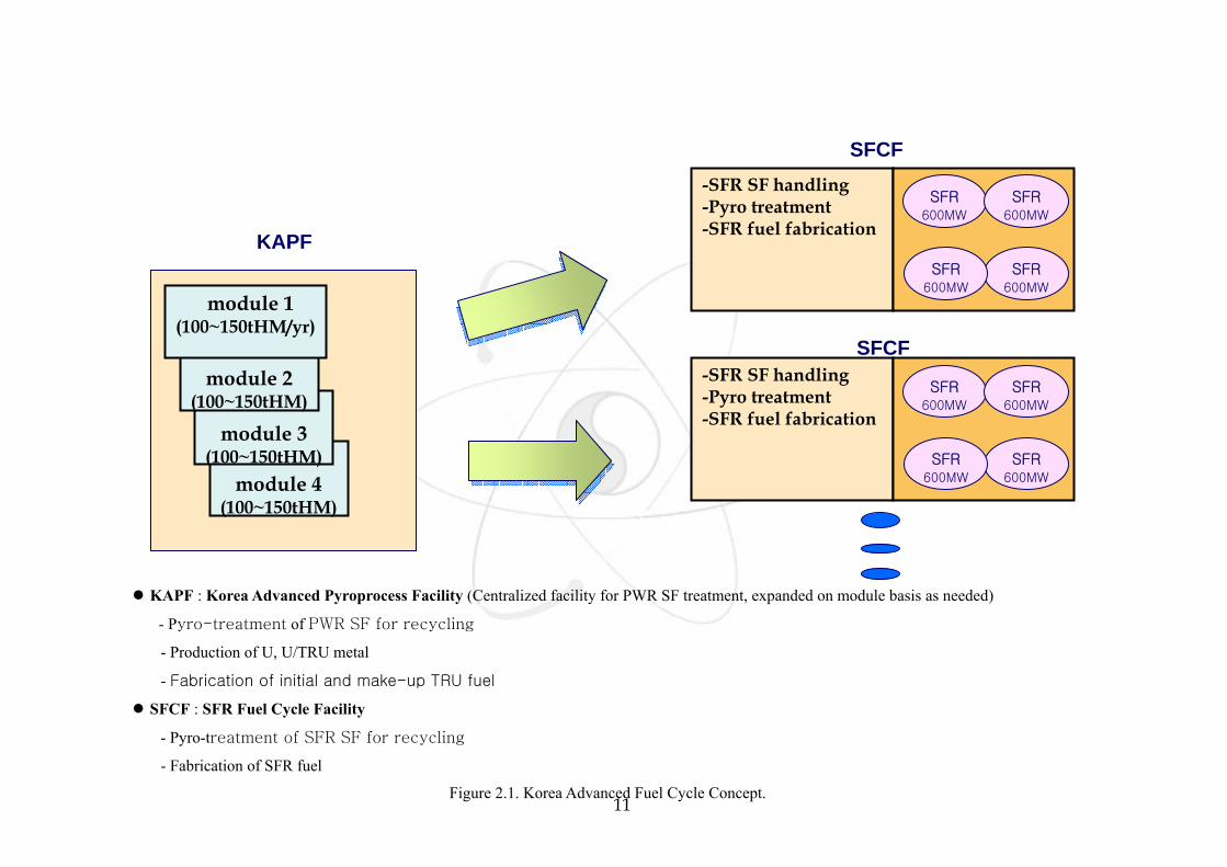
The primary functions of the KAPF are summarized in the following sections. The Korea
Advanced Fuel Cycle Concept and the Flow Diagram of processes in KAPF is shown in
Figure 2.1, 2.2 and 2.3.
2.2.1 Materials Receipt and Storage
The KAPF will provide the capability to receive spent fuel shipments from commercial
PWR reactors. The facility will be capable of receiving either truck or railcar mounted spent
fuel shipping casks. The capability to inspect, temporarily store, and move nuclear material to
manage the accountability and flow of materials into head-end preparation process will be
provided. Equipment will be provided to remotely handle, monitor, inspect and temporarily
store radioactive material in a suitable environment that provides for an adequate level of
safety (shielding, confinement, heat removal, monitoring, etc.) and security. Storage systems
and handling equipment will be designed to assure safe handling of all nuclear materials.
11
module 4
(100~150tHM)
KAPF : Korea Advanced Pyroprocess Facility (Centralized facility for PWR SF treatment, expanded on module basis as needed)
- Pyro-treatment of PWR SF for recycling
- Production of U, U/TRU metal
- Fabrication of initial and make-up TRU fuel
SFCF : SFR Fuel Cycle Facility
- Pyro-treatment of SFR SF for recycling
- Fabrication of SFR fuel
Figure 2.1. Korea Advanced Fuel Cycle Concept.
-SFR SF handling -Pyro treatment -SFR fuel fabrication KAPF
SFCF
SFCF
module 3
(100~150tHM)
module 2
(100~150tHM)
module 1 (100~150tHM/yr)
SFR 600MW
SFR 600MW
SFR 600MW
SFR 600MW
-SFR SF handling -Pyro treatment -SFR fuel fabrication
SFR 600MW
SFR 600MW
SFR 600MW
SFR 600MW

12
PWR SF Head-end Process (400~600 tHM/y)
- Disassembling, - Rod Slitting/Decladding - Voloxidation - NFBC Cutting/Compaction
Module #1 (100~150 tHM/y) - Electrolytic Reduction - Electrorefining - Electrowinning - Cathode Process - U Products Production - Salt Purification - MC&A, QA/QC
PWR SF Reception (400~600 tHM/y)
PWR SF Buffer
Storage (200 tHM)
SFR Fuel
Dispatch (5~8
tTRU/y)
SFR Fuel Assembling (5~8 tTRU/y)
& Buffer Store (5~8 tTRU)
Module #2 (100~150 tHM/y) - Electrolytic Reduction - Electrorefining - Electrowinning - Cathode Process - U Products Production - Salt Purification - MC&A, QA/QC
Module #3 (100~150 tHM/y) - Electrolytic Reduction - Electrorefining - Electrowinning - Cathode Process - U Products Production - Salt Purification - MC&A, QA/QC
Module #4 (100~150 tHM/y) - Electrolytic Reduction - Electrorefining - Electrowinning - Cathode Process - U Products Production - Salt Purification - MC&A, QA/QC
SFR Fuel Rod/Elemen
t Production
(5~8 tTRU/y)
Figure 2.2. Concept of the Main Hot Cells for KAPF.

13
Waste Salt
U+TRU+ RE
U recover
Reuse (SFR / CANDU) or Store as LLW
SFR
Salt recycle/ Waste form
U +TRU+RE U +TRU + RE
Off-gas treatment
I2, Kr, Xe, Cs, Tc, Ru, Rh, Te, Mo
Air
U3O8+ (TRU+FP)Oxide
Hulls
LLW
UO2
PWR Spent Oxide
fuel
Electrolytic reduction
TRU recovery (Liquid cathode)
Electro- refining
Dis- assembly
Vol-oxidation TRU fuel fabrication
Figure 2.3. A Flow Diagram of Pyroprocess in KAPF.

14
2.2.2 Front-end Process
Spent Fuel Disassembly and NFBC Compaction
The KAPF will provide the capability to pre-treat (e.g., unload, disassemble, cut/
compact, grind, etc), and provide material accountancy for various kinds of nuclear material
and spent fuels. The head-end process operation starts by moving a spent PWR fuel assembly
in lag storage to a fixture, which lays down the assembly on the clamp table to fix the
position that is suitable for top plate removal by a nearby cutting/dismantling device. Once
the top plate is removed, a fuel-rod gripping and pulling system, which is sliding back and
forth on another table in line with the clamp table, moves to access the fuel-rod tip
array already in exposure. Fuel rods can be pulled out in several ways, depending on the
gripper design: one by one, row by row, or a whole array of rods at once. Rods removed from
the remaining nonfuel bearing components (NFBC) are collected and rearranged in a compact
array (consolidation) by a suitable device or system that may be part of the rod extraction
system. Otherwise, a system-specific approach may have to be adopted, with appropriate
facility provision for such a special system.
Fuel Pin Chopping/Slitting and Decladding
The function of the chopping and decladding process provides a possible means to
recover spent fuel materials from fuel rods. High recovery ratio of fuel is required to reduce a
loss of spent fuel material, which has a common target level of over 99.9% of a fuel recovery
ratio. After pulling the fuel rods from the fuel assembly, cladding tubes are sheared axially
and cut into several pieces with a length of about 200 mm. Several decladding techniques can
be adopted in the oxidative decladding process, the fuel expands and disintegrates into fine
powder, and separates it from the cladding tube. In the oxidative decladding process, after
placing the fuel species in a furnace and heating them, the fuel pellets are pulverized into
powders through an oxidation from UO2 to U3O8 at 500 ºC under an air atmosphere. During
this oxidation step, volatile fission gases such as I, Kr, C-14 are evolved except for a
complete removal of tritium. After an oxidation, a separation step of the pulverized fuel and
cladding is required. Separation of the fuel materials as fragment shapes from the cladding
tube is also required. Both NDE and sampling techniques shall be used to determine the
amount of fuel retained with the discarded cladding. Conventional volume reduction
processes shall be used to treat the discarded cladding and to package it for storage or
disposal.

15
High Temperature Voloxidation
The objective of the advanced voloxidation process is to provide a means to recover fuel
from the cladding, and to simplify the downstream processes by removing volatile and
semi-volatile fission products prior to the following pyroprocessing. During this process at an
elevated temperature, a substantial amount of volatile and semi-volatile fission products are
released from the spent fuel. Pulverized powder recovered from the decladding process is
placed into a high temperature voloxidizer. Operating parameters include the temperature,
oxidant, oxidant flow rate and vibration, etc. Advanced voloxidation process to increase the
removal ratio of volatile and semi-volatile fission products which possibly includes I, Cs, Tc,
Ru, Te, Mo should be operated at about 1,250 oC under vacuum condition. Proper adsorbents
and techniques to trap and recover the fission products evolved from the voloxidation process
should be applied.
2.2.3 Pyroprocess
Following head-end processing tailored to subsequent steps, the fuel components will be
separated using technologies referred to as “dry” molten salt pyroprocess methods.
pyroprocess will include all provisions for timely, safe, and secure operations (e.g., process
recycle, criticality control, security, integrated process control, sampling, and MC&A) at the
proposed processing rates.
Electrolytic Reduction
In an electrolytic reduction process which includes an oxide reduction and cathode
consolidation step, spent PWR fuel is electrochemically reduced to a metallic powder form,
which is smelted into an ingot to be treated in the next process. The vol-oxidized oxide
powder is charged into an integrated cathode with a basket and converted to a metallic
powder form by an electrochemical method in a LiCl-Li2O molten salt. The salt-soluble FPs
such as a small amount of alkali and alkali earth elements with a high radioactivity are
dissolved in the form of chloride and transferred from the integrated cathode containing the
spent oxide fuel to a LiCl-L2O molten salt during an oxide reduction step. U/TRU/RE/NM
oxides are reduced electrochemically at the cathode basket to their metal forms, and oxygen
gas is evolved at the anode. Accordingly, all of the materials excepting for the alkali and
alkali earth elements remain in the integrated cathode, whereas the alkali and alkali earth
elements are transferred to the bulk of the molten salt as a chloride form. The reactions in the

16
oxide reduction step are as follows:
At the cathode,
Li+ → Li + e-
MxOy + 2yLi → xM + yLi2O
At the anode,
O2- → 1/2O2 + 2e-
The assumptions in the electrolytic reduction process for a material balance are as
follows: Reduction conversion and recovery yield in the oxide reduction step reach higher
than 99.5 %. In the cathode consolidation step, unreacted oxides are removed from the metal
ingot and recycled in the oxide chlorination step to dissolve the TRU and rare earth oxides.
The resulting uranium oxide is transferred to an electrolytic reduction step in order to reduce
the uranium oxide to metal. The remaining salt containing TRU and rare earth chlorides is
introduced to an electrowiner in order to recover TRU. During the cathode consolidation, the
molten salt is fully recycled for an oxide reduction. Accordingly, no elements are lost during
this process.
Uranium Electrorefining
Electrorefining process separates the uranium from the metallic form that is a product of
the reduction process of the spent PWR fuel. All the metallic elements are oxidized and
dissolved into the salt solution at the anode, whereas more noble elements remain in the
anode basket. The adhered salt in the recovered uranium deposit is distilled by the cathode
process, and subsequently a pure uranium ingot is obtained.
The electrolyte salt is a eutectic mixture of LiCl and KCl containing ~9 wt% of UCl3.
Pure uranium in the salt is deposited at the solid cathode. The transition metal fission
products are unable to be oxidized and remain in the anode basket as metallic elements. The
rare earth fission products and transuranic elements are not allowed to deposit at the solid
cathode under a general electrorefining condition which is normally 0.5~1 V of a cell
potential and 500 oC of the temperature. The chlorides of the transuranic elements and the
rare earth fission products are more stable than uranium chloride so that these elements can
not deposit at the solid cathode as long as the uranium concentration in the electrolyte salt is
sufficient enough to preserve the following reaction.
UCl3 + TRU(RE) → U + TRU(RE)Cl3

17
The adhered salt in the uranium deposit is normally removed by the cathode process
under the condition of 1300 oC and ~0.2 Torr. Pure uranium ingot is subsequently obtained
after a distillation of salt in the same cathode processor. Part of the pure uranium is
transferred to the chlorination process in which the RE/TRU oxide dross generated from the
cathode consolidation process reacts with the transferred uranium. The following reaction
balances the amount of uranium for the chlorination of the RE/TRU dross;
RE2O3 + 2UCl3 → 2RECl3 + UO + UO2,
TRUO2 + UCl3 → TRUCl3 + UO2
The inputs to the electrorefiner are mainly composed of the fuel and dross from the
cathode consolidation process, and the initial loading of uranium as UCl3. In the
electrorefiner, most transition elements remain in the anode basket at ~99.7% of an uranium
dissolution efficiency. This anode sludge is transferred to the metal waste processing step and
returned back to the electrorefiner as UCl3. In the cathode process, 30% of the salt which is
adhered to the uranium deposit is completely recycled to the electrorefining process. The
amount of uranium for the chlorination of the RE/TRU dross depends on the quantity of the
dross. Hence, part of the uranium product is transferred to the RE/TRU chlorination process
and most of the dissolved rare earth fission products are delivered to the electowinning
process with TRU as a chloride form.
TRU Electrowinning
In the electrowinning process, TRU, uranium and small amounts of the rare earth fission
products are recovered by the use of a liquid cadmium cathode (LCC) after electrorefining
operation in the case of the treatment of the spent PWR fuels. When the TRU is
electrodeposited in the liquid cadmium cathode their chemical activities are reduced owing to
a formation of intermetallic compounds such as PuCd₆ . Accordingly, the TRU is
co-deposited with some uranium and lanthanide elements in the LCC of the electrowiner.
This electrowinning process also includes cadmium distillation and TRU drawdown steps in
order to recover the TRU product from a cadmium-TRU alloy in a LCC and to convert it into
an ingot and to completely recover the TRU elements from the LiCl-KCl salt which is
discharged from an electrowinner before the fission products are removed from the salt in the
salt purification system.
Molten salt electrowinning is an electrolysis process in which the material to be
recovered is present as a metal halide compound in an electrolyte salt. The molten salt

18
containing the dissolved spent fuel constituents is placed in an electrowinning cell, with a
potential applied between the anode and cathode. At an appropriate decomposition potential
which depends on the species to be recovered, actinides can be deposited in the LCC.
TRU and rare earth fission products are accumulated in the electrolyte salt by increasing
the number of batches operated in the electrorefiner. When the U/TRU ratio or the level of
decay heat in the salt reaches the limiting value, deposition of uranium is completed and the
salt is transferred to the electrowinner. The LCC in the electrowinner consists of a small
amount of liquid cadmium contained in a ceramic crucible suspended in the electrolyte salt.
At the LCC, TRU ions are reduced to their metallic forms by combining them with electrons
and an alloying with Cd to form cadmium intermetallic compounds such as PuCd₆ . In the
liquid cadmium cathode, the Gibbs free energy for a formation of uranium, TRU and some
rare earths chlorides are very close to each other. As a result, TRU cannot be selectively
separated from the rare earths. Some amount of the rare earths and uranium will be recovered
together with TRU. Selective separation of plutonium in TRU is not possible as the standard
potentials among the TRU are very close to each other in the liquid cadmium metal.
The cadmium-TRU alloys in a liquid cathode of the electrowinner are transferred to a
cadmium distillation unit after a desirable amount (up to about 10 wt% of cadmium) of TRU
material has been collected. The cadmium is distilled selectively from the cadmium-TRU
alloys due to its lower melting point than other TRU metals. As a result, TRU, U and some of
the rare earths are consolidated after distilling the cadmium. The cadmium metal is recovered
for a recycling. The TRU, U and some of the rare earth metals are converted into ingots for a
transfer to the fuel fabrication system. Small amount of actinide metal (U and TRU)
remaining in the salt used in the electrowinning process is treated by a drawdown step to
remove it from the salt before transferring it to the salt purification process.
The material balance in the electrowinner is estimated by calculating the distributions of
U, TRU and rare earths between the molten salt and cadmium phase based on an
electrochemical equilibrium. The recovery yields of TRU and rare earths are about 98.3% and
1.1% in the LCC, respectively, while U is entirely recovered from the salt phase at a cathode
potential of -1.6 V (vs. Ag/AgCl) in the electrowinning process. The salt including TRU and
rare earths discharged from an electrowinner is injected to the drawdown unit, where TRU is
recovered to return it to the electrorefining step and the TRU-free salt is transferred to the salt
purification process. About 10% of rare earths in the salt are contained in the TRU stream to
be recycled to the electrorefiner. Fraction of TRU recovered from the total TRU contained
in the spent fuel eventually reaches 0.9995.

19
2.2.4 Pyroprocess Material Treatment, Handling and Storage
The pyroprocess material handling function of the KAPF includes material collection;
analysis for criticality control, MC&A, security control, solid product formation, handling,
packaging, and interim storage of conditioned and separated materials. The KAPF material
packaging function will provide the capability to isolate and package various separated
materials. Material storage will provide adequate surge capacity to allow efficient production
operations and to provide material when it is needed.
2.2.5 SFR Fuel fabrication
The KAPF fuel fabrication function will be capable of manufacturing fresh SFR fuels.
The facility will provide the capability to remotely manufacture and inspect fuels. Packaging
and temporary storage of manufactured fuel will be provided in addition to provisions for
scrap recycle, criticality control, security, and MC&A.
As a result of the pyroprocessing of the spent oxide fuels discharged from PWRs, TRU
alloy products are obtained from the electrowinning process. Fuel fabrication process which
uses an injection casting method produces the metallic fuel rods containing TRU
(U-TRU-Zr-RE metal alloy) to transmute long-lived nuclides in the generation IV candidate
SFR. The main equipment in the fuel fabrication process consists of the injection casting
machine, the pin processor, and the assembly fabrication, etc. TRU alloys are sent to a fuel
fabrication process to prepare fuel pins and assemblies for transmuting the long-life
radionuclides. Uranium ingots recovered from an electrorefining step are blended with the
TRU alloy in the injection casting step.
The metallic fuel contains U, TRU,. It is assumed that the ratio of U:TRU:Zr is
60:30:10(in case of burner reactor). To satisfy this fuel specification, recycled U and Zr are
added to the TRU product.
2.2.6 Waste Treatment, Handling and Storage
The waste handling function includes waste analysis and certification, treatment,
packaging, inspection, monitored interim storage, and MC&A. The KAPF will provide the
capability to produce new waste forms, and treat, package, and temporarily store all required

20
waste types. Treatment and testing capabilities will be available to convert waste streams to
meet applicable waste acceptance criteria. Control and testing capabilities will normally
assure an acceptable and certified waste package is produced but facilities and flexibility for
re-work of off-specification waste forms will be available. Monitoring and storage areas will
be provided as required for integrity testing and interim storage observations.
Trapping of Fission Gases Arising from Voloxidation process
Trapping of the volatile and semi-volatile fission products released from the high
temperature voloxidiation process is necessary to safely operate the pyroprocess and to
minimize the emission of the evolved fission products to the environment. Target fission
products to be trapped are chosen based upon their radioactivity, environmental toxicity, and
on the basis of the release rates of the volatile and semi-volatile fission products.
Removal efficiency of the target fission products depends on the voloxidation
temperature and time. Assuming that the voloxidation temperature is about 1,250oC under
vacuum condition, volatile and semi-volatile fission products are removed within a level of
following table.
Removal percent of target fission products by voloxidation, % Voloxidation Temperature
H-3 C-14 Kr-85 I-129 Cs Tc Ru Rh Te Mo
1,250ºC 100 100 100 100 98 100 100 80 90 80
The off-gas treatment system for trapping the volatile and semi-volatile fission products
is designed based on the estimated amount of fission products evolving from the voloxidation
process of the spent fuel, and the unit process in the trapping system is arranged to effectively
remove an individual fission product by considering the thermo-chemical properties of the
target fission products to be trapped. Semi-volatile fission products such as Cs, Rh, Tc, Mo,
Te have easy condensation properties on the process line if the temperature is below its
melting point. These fission products are trapped in front of the off-gas trapping system near
the exit of the voloxidizer. Fission products group I are Cs, Rh which are trapped on a fly-ash
filter at around 800 oC, and group II of Tc, Mo, Te on an alumino-silicate adsorbent at about
600 oC. Volatile fission gases of I, H-3 and C-14 are trapped in series on each trapping unit,
and an emission of Kr-85 noble gas is controlled by using a decay tank.
Volatile and semi-volatile fission products in a gas stream are transferred to solid

21
adsorbent phases. Trapping efficiency criteria for removing the target fission products may
affect the amount of adsorbent waste generation from the off-gas trapping system. It is a
general consideration that the decontamination factor of the whole trapping process should be
established for a safe operation level and a maximum allowable emission concentration to the
environment.
Salt Purification and Ceramic Waste Treatment
For the reduction of the amount of waste generated from both an electrolytic reduction
(LiCl) and an electrowinning (LiCl-KCl eutectic) process, the FPs involved in both waste
salts such as Cs, Sr and rare-earth elements with a trace amount of TRU are separated from
the waste salt by using a zeolite ion-exchange, carbonation and a precipitation method,
respectively. Pure salts recovered via the salt purification process are reused in the main
processes. The separated FPs are treated for the fabrication of the final waste form: a ceramic
waste form (Cs case) and vitrified waste forms (Sr and RE/TRU cases).
The waste LiCl salt from the electrolytic reduction process contains Sr and Cs. First, Sr
is precipitated into the form of a carbonate (SrCO3) by an addition of Li2CO3. Then SrCO3
separated from the molten LiCl salt is converted into its oxide form (SrO) through a thermal
decomposition. Finally, SrO is fabricated to a vitrified waste form.
SrCl3+Li2CO3 → SrCO3+2LiCl
SrCO3 → SrO + CO2(g)
In the case of Cs, a substantial amount of Cs is released from the high temperature
voloxidation process, but a small amount of Cs still remains in the LiCl salt. By applying an
ion-exchange process with an inorganic material such as zeolite, a small amount of Cs is
removed from the waste LiCl salt and then fabricated to a ceramic waste form with an
addition of a solidification agent (such as glass frit). After separating Cs and Sr from the
waste salt, the cleaned LiCl is recycled to the electrolytic reduction process. Cs, which is
released from the high temperature voloxidation process, is captured by a fly-ash media and
then is fabricated to a ceramic waste form.
The waste LiCl-KCl salt from the electrowinning process contains a considerable amount
of rare-earth elements and a very small amount of TRU. Rare earth and TRU elements are
precipitated into their oxide or oxychloride forms via a reaction with oxygen gas. When the
precipitates are fully settled, the upper layer that is mainly composed of a pure LiCl-KCl salt
is separated from the precipitate part containing the rare earth elements. The remaining salts

22
in the precipitate phase, which is a mixture of the precipitates and eutectic salt residue, are
separated and recovered from the precipitates by using a vacuum distillation/condensation
method. Finally the remaining rare-earth precipitates are converted into stable oxides by a
simultaneous dechlorination and oxidation reaction.
RECl3+0.5O2→REOCl+Cl2(g) or RECl3+O2→REO2+1.5Cl2(g)
REOCl+0.25O2→0.5RE2O3+0.5Cl2(g)
Over 99.6% of a conversion efficiency of SrCl2 into a carbonate form was obtained at an
operation condition of a Li2CO3/SrCl2 molar ratio of 3 or more. In the conditions of 650℃ of
a molten salt temperature, 420 min of an oxygen sparging time, the conversion to a
precipitate of the rare-earth elements exceeded 99.9%. The inorganic materials containing Cs
and some free salt residue are fabricated into a ceramic waste form by adding of a
solidification agent and glass frit. The fly-ash media used for capturing Cs from the
voloxidation process is mixed with a glass frit to produce another Cs-contained ceramic
waste form.
The rare-earth elements involved in the waste LiCl-KCl eutectic molten salts are
precipitated by the reaction with oxygen gas and then finally converted into oxides (RE2O3).
To fabricate vitrified waste forms, each stream of strontium oxides and rare earth oxides is
mixed with the glass frit.
Metal waste treatment
Metal wastes are divided into two large groups; cladding hull and insoluble noble metal
fission products from the electrorefiner. In this step, these materials are rinsed to get rid of the
adhered fissile materials and melted to produce a corrosion-resistant metal alloy.
The fissile materials remaining on a hull or insoluble noble metal are dissolved in a
LiCl-KCl salt by using zirconium chloride as follows;
1.5ZrCl4+RE2O3→1.5ZrO2+2RECl3, ZrCl4+UO2→ZrO2+UCl4
The noble metal fission products containing a small amount of actinides left behind in
the anode basket after the electrorefining process are also rinsed to remove the actinide
elements by the aforementioned dissolution reaction.
The actinide and fission product chlorides are transferred to the electrorefiner and the
residual metallic fission products are melted together with the cladding hull and an additional
stainless steel to produce a corrosion-resistant metal alloy at a moderate temperature.

23
Cladding hull contains ~0.01% of the actinides and fission products after chopping and
decladding. Also, anodic dissolution yield of the uranium is limited below ~99.7 % to retain
the noble metal fission products (e.g. Rh, Te, Mo and Pd) at the anode basket as much as
possible. So, anode sludge contains all the noble metal fission products and ~0.3% of
uranium. In the partial dissolution and rinsing step, ~99% of the actinides and fission
products are dissolved and return back to the electrorefiner. The recovered noble metal fission
products and cladding hull are melted together with an additional stainless steel to decrease
the casting temperature and to enhance the corrosion resistance. Accordingly, 10-4 % of the
actinides remain in the metal waste.
2.2.7 Shipping
The KAPF will provide processes and equipment necessary to support truck and rail
transfers to and from, and within the KAPF. These transfers include shipping manufactured
fuels, by-products, waste, failed equipment, and other items generated by facility operation.
Shipping processes will include provisions for cask loading, industrial and radiological safety,
Department of Transportation (DOT) compliance and inspection, criticality control, security,
and MC&A.
2.2.8 Safeguards and Security
The safeguards and security function will meet all current DOE requirements for the
production, storage, and transportation of Category I special nuclear material (SNM), in a
manner sufficient to prevent theft, unauthorized use, or radiological sabotage by an adversary
force as defined in the current DOE Design Basis Threat. The facility design will incorporate
innovative, state-of-the-art protection system features to ensure adequate protection, mitigate
the impact of future changes in the Design Basis Threat, and minimize the number of
Protective Force personnel required to achieve a level of protection that is acceptable to the
DOE. The KAPF will provide the capability to develop advanced safeguards implementation
scheme for licensing, regulating, and/or monitoring full-scale commercial facilities. The
KAPF will comply with all Department of Energy (DOE) MC&A requirements. It will also
provide the capability to develop and demonstrate advanced compliance methods related to
the Nuclear Regulatory Commission (NRC) and International Atomic Energy Agency (IAEA)
requirements.

24
2.2.9 Instrument & Control (I&C) Infrastructure
The I&C infrastructure for the KAPF will include facility-wide data collection, data
management, control action, material accountability, human data interface, and modeling
systems to support operation of commercial-scale advanced production. The I&C system
provides the cross-cutting interconnections and human data interfaces between each of the
primary facility functions and allows for their seamless operation. This infrastructure will
support a flexible, modular, state-of-the-art design for ease of maintenance, reconfiguration,
and operation of productions.
2.2.10 Safety
The KAPF Project will comply with Title 10 Code of Federal Regulations, Part 830,
(Nuclear Safety Management), Subpart B (Safety Basis Requirements), and DOE Order
420.1B (Facility Safety). The project will also comply with all other applicable laws,
regulations, DOE Orders, Standards, Guides and applicable national consensus standards
related to safety. The project will initiate compliance with the current draft of
DOE-STD-1189-2006 (Integration of Safety into the Design Process) during the conceptual
design phase, and shall be fully compliant with the requirements contained in the final
Standard in accordance with the project compliance plan to be developed and implemented
upon approval of the Standard. All Documented Safety Analysis and other safety
documentation deliverables will be developed in accordance with requirements contained in
DOE Order 413.3 Project Management for each phase of the project. The project safety
system, structure, and component selection process will be implemented in a manner such
that selected controls meet current requirements and are also flexible enough to support
changing processes and requirements over the KAPF design lifetime.
2.2.11 Quality Assurance
The KAPF Project is required to comply with Title 10 Code of Federal Regulations, Part
830, Subpart A and DOE Order 414.1C for Nuclear Facilities and Activities. The use of
applicable elements of American Society of Mechanical Engineers (ASME) Nuclear Quality
Assurance-2000 (NQA-1-2000) has been adopted for the KAPF Quality Assurance Program.

25
3.0 KAPF Performance Requirements This section defines the performance, design, and regulatory requirements for a
commercial size KAPF facility capable of converting 600 tHM/y spent PWR fuel into metal
fuel for use in the SFR reactors. These requirements were intended to guide the conceptual
design of a facility which in turn was used to estimate the cost of design, licensing,
construction, operation, and decommissioning of the commercial size KAPF.
The requirements are based upon the assumption that the facility will be constructed and
operated in the United States, and at KAERI's request, will be required to meet the equivalent
of U.S. Nuclear Regulatory Commission's requirements governing safety, security and
safeguards. For a KAPF to be located in the Republic of Korea, adjustments may have to be
made to accommodate different conditions imposed by local external events as they relate to
structural design considerations. The facility will also be designed and operated to meet all
IAEA requirements for nuclear material safeguards under the Nuclear Weapons
Non-Proliferation Treaty.
3.1 Overall Performance Requirements
3.1.1 Plant Capacity
The design throughput of the KAPF facility shall be 600 tHM of spent PWR fuel per
year. Centralized stand-alone facility, Modular type in which hot cell lines (100~150
tHM/module.y) can be expanded as needed.
3.1.2 Plant Availability
The facility shall be sized and operated for assuming an average of 70% plant production
availability (i.e., equivalent 250 full operating calendar days per year). This 70% availability
requirement for the KAPF shall cover allowances for normal process systems startup and
shutdown times, scheduled and unscheduled plant equipment maintenance and repair
activities, material accountability related tasks that affect plant operation, and any scheduled
plant-wide outage period for major systems refurbishing activities (e.g., a scheduled
one-month long plant-wide outage period per year for refurbishing one or more of the
equipment in the plant). Runouts will be performed at the completion of each production
campaign to meet Nuclear Regulatory Commission accountability and safeguards

26
requirements. Runouts will be expected to require approximately one shift of operating time
to complete. Cleanouts will be required six times per year. Cleanouts will require
approximately one and one-half shifts of operating time to complete.
3.1.3 Plant Design Life
The design life of the facility shall be 60 years. But, equipment design life-time shall be
10 years for the long life items and 5 years for short ones.
3.1.4 Plant Location
The structural design is based on conditions of external events of a facility site located in
the United States. For a KAPF to be located in the Republic of Korea, adjustments have to be
made for different conditions of external events for structural design considerations. The cost
evaluation is also based on a facility which is constructed and operated in the United States.
The costing structure and parameters will allow KAERI to convert the cost results for facility
site in the Republic of Korea.
3.1.5 Reference PWR Spent Fuel
The reference feed stock used in the KAPF is Korean Yonggwang Nuclear Station Unit 3
& 4's (YG 3&4) 16x16 standard PWR spent fuel assemblies with a minimum of 10 years of
cooling time after discharge from the reactor. The design data and burn-up characteristics of
the reference spent fuel feed stock are provided as follows:

27
Design Parameters of the Reference Spent Fuel:
Plant YG 3&4
Reactor Type PWR
Rod Array 16×16
ABB-CE Supplier
(KSFA)
Rod/Ass.
Ass./Core
236
177
Total Length(㎝)
Fuel Length(㎝)
Width(㎝)
452.8
409.4
20.7
O.D of Rod(㎜)
Clad Thick.(㎜)
9.91
0.635
Total Weight(㎏)
Uranium(㎏)
Zircaloy(㎏)
653.6
428
135
Enrichment (wt%) 2.4~4.5 (Reference 4.5)
F
U
E
L
A
S
S
E
M
B
L
Y
Specific Burnup (MWd/kgU) 55
10.4
Pellet Density (g/cm3)

28
Fissile Contents of Reference Spent PWR Fuel:
4.5wt.%, 55GWD/MTU Nuclide
Grams wt.%
u234 1.97E+03 0.021
u235 7.12E+04 0.755
u236 6.37E+04 0.675
u238 9.15E+06 97.063
Total U 9.29E+06 98.514
pu238 4.32E+03 0.046
pu239 6.35E+04 0.673
pu240 2.99E+04 0.317
pu241 1.50E+04 0.159
pu242 1.02E+04 0.108
Total Pu 1.23E+05 1.302
np237 8.62E+03 0.091
am241 4.76E+03 0.050
am242m 1.53E+01 0.000
am243 3.03E+03 0.032
cm242 1.60E-01 0.000
cm243 9.32E+00 0.000
cm244 1.14E+03 0.012
cm245 6.34E+01 0.001
cm246 1.27E+01 0.000
Total MA 1.76E+04 0.187
Total 9.43E+06 100.000

29
3.1.6 Reference SFR Fresh Fuel
The product of the facility shall be SFR fuel assemblies. The design specifications of the SFR fuel are provided as follows: Bunner(Reference) Break-even(Alternative) Thermal Power: ? MW ? MW Number of Assemblies per Reactor: ? ? Specific Burnup: ? MWd/kgU Fuel Material Composition 70U-26Pu-4MA-10Zr wt.% 86U-12Pu-2MA-10Zr wt.%Density of Fuel Material 16.26 g/cm3 16.23 g/cm3 Fuel Pin OD 6.03 mm 6.03 mm Fuel Pin Length 930 mm 930 mm Fuel Rod OD 9 mm 9 mm Fuel Rod Length mm mm Fuel Assembly width mm mm Fuel Assembly Length mm mm No of Fuel Rod/Fuel Assembly: 271 271 Fuel Pin Weight 0.47 kg 0.47 kg TRU Weight/ Fuel Pin 0.141 kg 0.066 kg Fuel Rod Weight 1.0 kg 1.0 kg TRU Weight/ Fuel Assembly 38.24 kg 17.85 kg Clad, Duct Material 1.0 kg 1.0 kg Duct Width ? mm mm Duct Length mm mm Na Weight/Fuel Rod kg kg
Reference SFR fuel

30
Fissile Contents of Reference Spent SFR(Burner)Fuel:
Reference Spent SFR Fuel/assembly
0.19 79 Cm245
0.01 2 Cm243
0.72 292 Am243
0.81 328 Am241
wt.% Grams Nuclide
100.00 40583 Total 2.97 1204 Total MA 0.12 48 Cm246
0.63 255 Cm244
0.05 20 Cm242
0.07 27 Am242M
0.38 152 Np237 24.84 10080 Total Pu 2.03 826 Pu242 1.57 639 Pu241 9.21 3739 Pu240 11.15 4523 Pu239 0.87 353 Pu238 72.20 29300 Total U 71.99 29216 U238 0.05 20 U236 0.04 18 U235 0.11 47 U234

31
3.1.7 Reference Transport Cask for PWR Spent Fuel
The KN-18 cask shall be used as the reference shipping cask for the spent PWR fuel.
Key characteristics of the shipping cask are as follows:
Items KN-18
Type of package B(U) type fissile class III
Loaded weight with cooling water (tons) 105
Loaded weight without cooling water (tons) 100
Loaded weight with shock absorber 122
Outside Diameter with shock absorber (mm) 3,592
Outside Diameter without shock absorber (mm) 2,351
Height with shock absorber (mm) 6,329
Height without shock absorber (mm) 5,159
Diameter of cavity(mm) 1,489
Fuel basket Boral+SS
Gamma rays shield A350 LF3
Neutron shield Borated PE rod
Shock absorber Spruce wood
Capacity 18 PWR SF
Burnup(MWD/tU)
Cooling time(yr)
Decay heat(kW)
Status Under developing by KEPCO

32
KN-18 Transport Cask.

33
3.1.8 Reference Transport Cask for Fresh SFR Fuel
Transport cask for fresh SFR fuel is not developed yet. It is assumed that the KN 18 cask
which is changed its internal basket, may be used as the reference shipping cask for the fresh
SFR fuel.
3.1.9 PWR Spent Fuel Lag Storage
The KAPF shall provide the capacity to store up to 200 tHM of spent PWR fuel, and
shall allow for the batching of fuel to adjust feed stock for the head-end treatment process.
3.1.10 SFR Fuel Storage
The storage and shipping system shall accommodate a minimum of one year of KAPF
production output. The system shall be based on dry storage technology.
3.1.11 Waste Storage
The storage system for the different forms of waste materials generated in the KAPF
facility shall accommodate the anticipated quantities over a minimum of 10 years of facility
operation. The storage containers shall be designed to facilitate eventual waste disposal.
3.2 General Requirements
The KAPF shall provide the capability to perfom pyroprocessing, remote fabrication of
SFR fuels, advanced safeguards, and advanced waste form fabrication. KAPF operations
shall contribute to a fully integrated and controlled fuel cycle by separating TRU elements
from spent PWR fuel and incorporating these into fuel for the SFRs. The KAPF operation
shall ensure criticality and safety in accordance with the latest ANSI/ANS 8.1, and
ANSI/ANS-8.10 as applicable. The KAPF shall provide equipment and other provisions to
recover from operation upsets or equipment failure and to create flexibility to increase
capabilities.
34
3.2.1 Design Approaches and Goals
Safety, technical flexibility, and economics are the major aspects in selecting optimal
alternative for system design. The safety-first principle is given the highest priority in the
design. Some tradeoffs will be inevitable when innovative technologies have to be
demonstrated at the facility for safety assurance. Many of the goals may, in effect, be
conflicting among themselves; the optimal compromise will have to be made in the order of
priority based on this design philosophy:
Radiation exposures are to be kept as low as reasonably achievable (ALARA).
Proven technologies are to be adopted whenever possible.
Flexibility for future modification shall be considered.
Optimal allotment and functional structure in the overall configuration of the
facility shall be achieved on ergometric and economic bases.
Spaces and functional provisions shall be adequate for all of the subsystems
proposed in the conceptual requirements.
Remote maintenance and other advanced concepts (e.g., automation) shall be
considered in system design, whenever feasible, toward ALARA principle and
for objectives of the facility.
Modularity of equipment shall be pursued in the design concept to facilitate
remote maintenance.
Preventive features of safety shall be embedded in local and global systems of
the facility.
Emergency preparedness and emergency recovery of the facility systems shall
be provided for.
Systems shall be designed so as to minimize radioactive wastes arising from
facility operation.
Eventual decommissioning of the facility is to be considered.

35
3.2.2 Applicable Codes, Standards and Regulations
Korean regulations to be applied to the design and licensing of the KAPF have not yet
been fully established. As many other foreign facilities with specific purposes do, the KAPF
has its own functions that may not be covered by any regulations. Applicable codes and
standards or regulations may be selected from those that have been applied to similar
facilities in foreign countries. The areas for which Korean regulations exist, however, shall be
governed by Korean regulations; e.g., radiation protection, transportation of waste,
contamination control, and, in rules of the Korean Ministry of Education, Science and
Technology (Korean MEST hereinafter), Korean Building Code and Korean Fire Protection
rules. Some areas of design and licensing may exist that are listed in the foreign codes and
standards or regulations, but are not appropriate for application to the KAPF. Examples may
include, but not be limited to, natural phenomena to determine design loads and physical
protection with severe standards. The contractor shall provide a list of those items required
by reference regulations. The decisions on the range or depth of application of those items
necessary for conceptual design of the KAPF should be made during the conceptual design
stage. For those whose impact may more or less be considered independent of the total design
or licensing effort and the total cost figures, the decisions will be made later.
3.2.3 SAFETY CONSIDERATIONS
The design of the KAPF shall be based on a fundamental safety philosophy that is
similar to those applied to nuclear power plants and other nuclear facilities built and being
operated in Korea. The overall radiological safety objective shall be to ensure that the
probability of radiological consequences is acceptably low. At the stage of conceptual design,
a conservative approach shall be taken in setting up the safety criteria so that trends of
licensing requirements and public acceptance in the foreseeable future are also considered. In
reviewing the results of KAPF conceptual design, tradeoff studies in relation to applied safety
features shall be performed, which will help realize the concept of "ALARA."
3.2.4 Facility
The layout and configuration of the facility shall be optimized for remote
operation and maintenance.

36
The facility shall be operable and maintainable without human intervention
in the shielded area.
The facility shall be provided with adequate remote systems and storage
spaces for radioactive materials and equipment to be handled or maintained
remotely.
The facility shall be provided with work areas for remote decontamination
and maintenance of failed equipment as part of special operation in the
facility.
The facility shall be provided with radioactive waste collection, treatment,
packaging and shipping systems. The facility shall also be designed to
minimize radioactive waste generation.
3.2.5 Equipment
The equipment shall be optimized for remote operation and maintenance.
The equipment shall be as light as possible to facilitate handling, transfer,
replacement, etc.
The equipment shall be modularized, as far as possible, to facilitate remote
maintenance.
Drive units of motors that are prone to failure shall be designed to facilitate
remote replacement and repair.
Equipment design life-time shall be 10 years for the long life items and 5
years for short ones.
The equipment shall be designed to maximize automation of the process
operation and control.
3.2.6 Instrumentation and Control:
The facility shall be provided with adequate instrumentation and control
(I&C) for facility operation, maintenance, and surveillance.
The I&C systems shall be designed to facilitate in-place calibration as
well as man-machine interface.
The I&C systems shall be designed to facilitate nuclear materials safeguards
and facility safety monitoring.
37
3.3 Materials Receipt and Storage Requirements
The KAPF shall provide the capability to receive spent fuel from commercial PWR
reactors. Incoming material is expected to have been cleaned to remove surface
contamination and foreign materials prior to shipment to the KAPF. Provisions for receiving,
inspecting, temporarily storing, conditioning and transferring SNF with high-radiation fields
and high decay heat shall be provided.
The facility shall provide an effective and efficient remote transfer system
between the interim storage areas (dry) and the fuel preparation cell.
Dry storage options must also consider leak detection, treatment options for
removing contamination, isolation of fuel, fuel cutting/preparation capabilities,
MC&A, security, etc.
The KAPF shall provide the capability to receive and offload incoming materials
from a truck or rail car.
The KAPF shall provide the capacity to store up to 200 tHM of spent PWR fuel,
and shall allow for the batching of fuel to adjust feed stock for the head-end
treatment process.
The KAPF shall provide the capability to store (on an interim basis) and transport
fuel to manage the flow of materials into each process.
The KAPF shall provide equipment to remotely handle and temporarily store
materials in a suitable environment that precludes loss of confinement and
provides safeguards and security commensurate with the attractiveness level.
The KAPF shall provide cask inspection, remote decontamination, spent fuel
repackaging and limited repair capabilities (turn-around maintenance only).
The KAPF shall provide the capability to provide inert cover gases where needed
to help assure product purity and package integrity
The KAPF shall receive, inspect, and accept incoming materials per applicable
regulatory requirements

38
3.4 Head End Processing
3.4.1 Disassembly and Batching
The KAPF shall provide the capability to receive a variety of SNM(special nuclear
material) and to remotely inspect, disassemble, package, interrogate, and remove unwanted
components (e.g., hardware, nuclear poisons, instrumentation, contaminants) prior to
transitioning to the next head-end operation. The KAPF shall also provide the capability to
remotely interrogate, inspect, and identify feed materials for the purpose of assessing SNM
content and for blending to achieve the desired byproduct isotopic concentrations.
3.4.2 Mechanical Treatment
The KAPF shall provide the capability to remove cladding, partition, and sort SNF
(special nuclear fuel), SNM, and other feed materials into physical dimensions that are more
suitable for follow-on thermal, and/or mechanical treatment. Provisions for contamination
control of fractured fuel, related fission product material, fission product gases, and airborne
solid contaminants shall be provided. Contamination control shall also be provided during the
transfer of conditioned material to the next head-end treatment station.
3.4.3 Thermal Treatment
The KAPF shall provide the capability to heat, within reactive or nonreactive gas streams,
the feed material to temperatures that: (a) create the desired physical form (e.g., fracture the
material and increase its surface area), and (b) remove the desired fission products. The
KAPF shall include provisions for trapping and packaging the volatile off-gases and air-borne
contaminants and remotely transferring the conditioned product to the next head-end station.
3.3.4 Product Clarification
The KAPF shall include provisions for remotely removing fine solids (e.g., fuel residues
and cladding fines) from each process. Provisions for remotely maintaining the solids
removal system and the transfer of solids to a solids packaging, interrogation, and transfer
system shall also be included. Off-gas control shall be provided.

39
3.3.5 Waste Treatment and Handling
The KAPF shall include remote handling capabilities to treat and package waste material
from all parts of the head-end operations (e.g., SNF hulls, SNF hardware, trapped off-gas
fission products, etc). Provisions to blend waste from the separations systems shall also be
included.
3.3.6 Process Off-Gas Control and Treatment
The KAPF shall include provisions to remotely treat and control chemical and
radiological contamination from each of the principal head-end operations, (e.g., mechanical
treatment, thermal treatment, off-gas treatment, etc). These systems shall maintain a negative
operating pressure relative to the hot cell HVAC to assure unexpected breaches or leaks in the
primary barrier (e.g., off-gas piping or equipment) shall retain contamination flow towards
the source.
3.5 Pyroprocessing
The KAPF shall include a capability for spent fuel constituents via pyroprocess
techniques.
The KAPF shall be sized to house pyroprocessing equipment operated in a
remotely maintained hot cell with an inert atmosphere.
The KAPF shall provide a commercial-scale pyroprocess system for converting
oxide feed material to metal.
The KAPF shall include provisions to ensure the hot cell high-temperature
processes provide adequate HVAC features to maintain desired cell
temperatures and inert gas purity, (e.g., maintain desired operating temperatures
for the equipment, thereby precluding damage to temperature sensitive items
and maintaining oxygen and water vapor levels in inert gas of up to several
vppm). Inert gas shall be recycled to the degree practicable.
The pyroprocessing section of the KAPF shall include features that assure the
timely availability of the remote equipment required for operations and
maintenance.

40
The KAPF shall provide electrochemical and other pyrochemical actinide-group
equipment to support recovery of U-Pu-minor actinide metal stream, which can
be used for remote fabrication of SFR fuel.
The KAPF shall provide pyrochemical sampling equipment that is remotely
maintained and designed to sample the various pyrochemical by-product and
waste streams, and operate dependably in high temperature and high radiation
fields.
The pyroprocess shall receive feed material that has been properly conditioned
by a head-end system.
3.6 Processed Material Handling and Storage Requirements
The KAPF shall provide the capability to sample, interrogate and/or package
blended separations and fuel feed materials.
The KAPF shall provide the capability to safely and securely store packaged
fuel fabrication feed materials for up to one month.
The KAPF shall provide for material monitoring, security, radiation shielding
and confinement, remote operations, and maintenance support, as needed.
The KAPF shall provide the capabilities and equipment to concentrate, solidify,
or otherwise immobilize product, as needed.
The KAPF shall provide the capabilities to monitor and transfer various
amounts and kinds of nuclear material within the facility in a safe and timely
manner.
The KAPF shall provide the capability to safely and securely package nuclear
materials for off-site shipment.
3.7 Fuel Feed Material and Scrap Conditioning Requirements
The KAPF shall provide the capability to blend combinations of in-process and
external source materials such as chemical solutions, molten metals, or dry
powders to achieve the required elemental and isotopic compositions required
for fuel fabrication.

41
The KAPF shall provide the capability to chemically adjust blended feed
materials to achieve the needed stoichiometry or to meet specifications for
chemical purity.
The KAPF shall provide the capability to handle metallic feed for metal fuel
fabrication.
The KAPF shall provide the capability to recover fuel materials and reblend for
reuse in fuel fabrication.
The KAPF shall provide the capability to transfer unblendable fuel scrap back
to separations for actinide element recovery.
The KAPF shall provide the capability to recover transuranics from scrap, fuel
fabrication off-specification material, and clean-up residues.
3.8 Fuel Fabrication Requirements
The KAPF shall provide the capability of manufacturing SFR fuels. The KAPF shall
perform commercial-scale fuel fabrication operations.
The capability to efficiently modify, remove, and reinstall equipment shall be
provided to fuel fabrication.
The KAPF fuel fabrication line shall be designed to minimize the amount of
waste generated.
The KAPF shall handle plutonium-bearing fuels to fuels containing substantial
quantities of minor actinides.
The KAPF fuel fabrication function shall provide efficient access to a
radiochemistry and fuel characterization laboratory to provide rapid turnaround
on chemical analysis, isotopic analysis, and fuel physical and thermal properties.
The use of on-line real time monitors (e.g., spectroscopic and electrochemical
meters) is favored wherever practicable.
The KAPF shall provide capability to conduct all necessary quality control
(QC) inspections and prepare quality assurance (QA) documentation in
accordance with appropriate DOE, NRC, and customer requirements.
The KAPF shall provide the capability to sample fuel products and materials
and conduct necessary QC inspections to meet all applicable requirements.

42
The fuel fabrication function shall be capable of receiving feed materials
directly from other areas of the KAPF.
The KAPF shall provide the capability to fabricate TRU-bearing metallic fast
reactor fuel pins for SFR.
The KAPF shall be capable of processing uranium (U) and TRU metal into fuel.
The KAPF shall provide the fuel fabrication throughput of about 8 tTRU for
SFR fuel (about 2 tTRU/module) annually.
The fuel pin and bundle design basis for conceptual design shall be the SFR fuel
The KAPF shall provide the capability to perform metallurgical bonding of
metallic fuel pins to their cladding using sodium metal.
The KAPF shall provide fuel assembly storage to provide space and controls for
staging of fuels in preparation for shipment.
The KAPF shall provide the capability to recycle fuel material scrap for
incorporation back into the fuel-fabrication process.
3.9 Waste Treatment, Handling and Storage Requirements
All generated effluent, waste, and products shall be treated as required for disposition or
release in an environmentally sound, safe form that meets all applicable waste treatment and
emission regulations and complies with the waste acceptance criteria for applicable licensed
disposal facilities.
All waste that requires temporary storage pending disposal pathway
development shall be stabilized in the expected final waste form, and shall not
be stored as a liquid in long-term storage.
The KAPF shall provide for final waste form disposition, by either treating the
waste or arranging for approved waste treatment by others.
Temporary waste storage shall be provided to decouple waste generation from
treatment, shipping, and disposal. Storage shall be interim and compliant with
material-specific requirements.
The KAPF shall provide the capability to produce advanced waste treatment
technologies, including utilities, space, instrumentation, analysis, and storage.

43
Waste treatment technology development shall include facility support for
metering liquid, solid, slurry feed, and support for chemical mixing and storage.
Waste treatment technology shall include facility support for blending and
encapsulating in media.
Waste treatment technology shall include facility support for gas heating,
cooling, wet scrubbing, and dedicated connections to facility non-radioactive
and radioactive off-gas vents.
The KAPF shall treat, monitor, and meet regulatory requirements for all of its
effluent streams.
3.10 Shipping Requirements
The KAPF shall provide packaging capability.
The KAPF shall provide temporary storage capacity.
The KAPF shall provide the capability to ship SFR fuel.
The KAPF shall provide the capability to ship new waste forms.
The KAPF shall provide the capability to ship laboratory and secondary waste
(TRU, LLW, hazardous, industrial, etc.).
The KAPF shall provide the capability to ship HLW in accordance with
relevant requirements.
The KAPF shall provide the capability to prepare packages for shipping
(decontamination, characterization, waste certification, etc.).
The KAPF shall provide the capability to maintain and repair shipping and
packaging containers.
The KAPF shall provide qualified shipping and packaging containers.
3.11 Facility Support Requirements
The facility support functions of the KAPF include the following:
Cold remote mock-up capability: The KAPF shall provide a cold mock-up and

44
equipment development area to support the assembly, fit-up, and functional testing
of equipment, and training prior to introduction to radiological areas. The KAPF
shall provide high-bay capability sized for the largest piece of process equipment.
Analytical services: The KAPF shall provide analytical capability that remotely
receives samples from throughout the KAPF. The analytical services area shall
provide the shielding, contamination control, safeguards and security, hazardous
material control and remote capabilities necessary to safely perform all analytical
measurements (e.g., hot cells, glove boxes and vented hoods).
Cold chemical makeup: The KAPF shall provide the capability to store, prepare and
deliver reagents and process gases as needed to support processes.
Infrastructure: The KAPF shall provide warehouse space for receipt and storage of
supplies, materials, spare equipment, etc. The KAPF shall provide facility features
and remote capabilities to support maintenance and testing of contaminated
equipment (maintenance of remote-handling systems and process equipment repair).
The KAPF shall provide secure storage, including interim storage, for the facility
by-products and feed stocks as required. Critical power supply and HVAC systems
for the command and control center shall be able to operate independently of the
KAPF and its operational status. The KAPF shall provide necessary back-up power
for critical systems, including process control, MC&A, security, lighting, and other
identified systems to provide continuous operation if primary power is lost. The
KAPF shall provide an integrated office space complex, with conference rooms and
support areas
Remote handling : The KAPF shall meet/maintain ALARA levels using remote
operation and maintenance methods as required. Remote handling shall be supported
by viewing systems that optimize the desired remote capability and retain high
reliability.
Atmospheric and radiological confinement control. : The KAPF ventilation system
shall assure airflows from areas of less radiological contamination potential to areas
of more contamination potential for normal and abnormal operating conditions. The
pressure differentials within the KAPF shall be maintained between confinement
zones to assure proper airflow direction. Air flow within KAPF shall be divided
into zones and monitored to identify the source of any abnormal radiological
releases. The KAPF HVAC system shall be designed in zones to provide

45
independent availability of key processes, i.e., allow separations area to operate
independently of upset conditions in the fuel fabrication area or SNF storage areas.
3.12 Safeguards and Security
The KAPF shall provide a system for addressing requirements for licensing KAPF using
current technologies to the greatest extent possible. The KAPF shall provide areas to perform
advanced safeguards monitoring, sampling, and analytical systems. These systems shall be
capable of interfacing with multiple points in the process, interfacing with multiple physical
states (i.e., liquid, solid, gaseous), and providing representative process information.
The KAPF shall provide a dedicated IAEA Inspector room with work space and
data retrieval capabilities. The KAPF shall also include dedicated IAEA
analytical chemistry laboratory space with in-process SNM measurement
equipment and data transmission capabilities on a selected basis.
The KAPF shall apply state-of-the-art physical safeguards and physical
protection systems, as required, to the facility, its equipment, content, and
nuclear materials.
The KAPF shall be encompassed by three security layers. SNM shall be located
(used, processed, or stored) within the Material Access Area (MAA) inside a
Protected Area (PA) with an additional security layer, an Extended Detection
Area (EDA), beyond the PA layer. The SNM shall be stored in a vault of
substantial construction, capable of incorporating an active denial system and
adequately protected by a defense-in-depth physical barrier strategy.
Vehicle and personnel barriers shall be incorporated into each security layer.
Barrier design shall provide sufficient delay time for the Protective Force (PF)
to engage unauthorized entry and sufficient “stand-off” distance to protect the
facility against the Design Basis Explosives Threat. Aircraft barriers shall be in
place to deny or deter use of aircraft for adversary insertion and facility
sabotage scenarios.
Access controls shall be in place to ensure that unescorted access to the KAPF
is restricted to appropriately cleared and authorized personnel.
The intrusion detection systems shall communicate to and annunciate at both a
Central Alarm Station (CAS) and a Secondary Alarm Station (SAS). The alarm

46
system shall use redundant, independently routed, or separate communication
paths and meet the requirements for safeguards and security alarm management
and control systems. The CAS shall be built underground.
3.13 Instrumentation and Control (I&C)
The KAPF shall provide I&C infrastructure that is flexible, modular,
state-of-the art and designed for ease of maintenance.
The KAPF shall provide a data collection system with the accuracy, reliability,
physical constraints, life cycle, quality, and security to support development,
test, production and R&D requirements.
The KAPF shall provide process control systems to collect all the information
that is required to maintain safe, secure and reliable process control, MC&A,
and modeling.
The KAPF shall maintain a standards control program that meets applicable
quality assurance (QA) and security requirements for the information.
The KAPF analytical area shall provide the remote capabilities necessary to
safely perform all analytical measurements.
The KAPF shall provide data handling capacity for distributing collected and
modeled data throughout the facility.
The KAPF shall provide for secure storage, retrieval and distribution of all data.
The KAPF shall provide control systems to ensure the safe and environmentally
sound regulation and interlocking of processes for all of its development
programs and technology demonstrations.
The KAPF shall provide control response systems for maintaining operations,
MC&A requirements, and technology demonstration goals.
The KAPF shall provide the remote capabilities necessary to safely perform
control actions.
The KAPF shall provide material accountability, including but not limited to,
SNM, other nuclear materials, and chemicals.
The KAPF shall be equipped to provide input to a computerized system to

47
maintain material inventory management throughout the facility.
3.14 Facility Decontamination and Decommission
The KAPF shall be designed to facilitate decontamination of equipment for maintenance,
repair and replacement, and to minimize costs of the eventual decontamination and
decommissioning. The facility shall include a decontamination area within the process or
operating area. This area shall be furnished with all necessary cleaning equipment,
radioactivity monitors, waste handling capability, and safety features to safely perform
equipment cleaning tasks. The facility design shall include features that will facilitate
decontamination for future decommissioning. The KAPF shall use modular, separable
confinements for radioactive and other hazardous materials to preclude contamination of
fixed portions of the structure.
3.15 Quality Assurance
The KAPF QA Program (QAP) shall implement the QA Criteria listed in DOE Order
414.1C, Quality Assurance, Section 4B and 10 CFR 830 Subpart A, Quality Assurance
Requirements, Section 830.122 using a graded approach as defined in the Project QAP
document. The KAPF QAP shall use national consensus standard NQA-1-2000, Quality
Assurance Requirements for Nuclear Facility Applications to develop and implement the
KAPF QAP.
The KAPF QAP shall integrate, as defined in the Project QAP document, the quality
management system requirements as defined in DOE O 414.1C, the suspect counterfeit
measure process defined in DOE O 414,1C, Attachment 3, the Corrective Action
Management Program as defined in DOE O 414,1C, Attachment 4, the Safety Software
Quality Requirements as defined in DOE O 414,1C, Attachment 5, and other quality or
management system requirements in DOE Directives and external requirements, as
applicable.

48
4.0 Cost Estimate
4.1 General Assumptions
The capital and operating costs were developed as if the facility described herein were to
be designed, fabricated, tested, licensed, and operated in the United States to the requirements
of KAPF. This assumption established labor rates, licensing fees, taxes, insurance rates and
general costs for equipment. Conservative estimates, as of December 2008, is used as this
type of facility has never been previously designed and built.
4.2 Scenario
The cost scenario was for a first-of-a-kind and overnight facility with a design
through-put capacity of 600 tHM of spent PWR fuel per year.
4.3 Methods of Cost Evaluation
The basic method used to develop the cost estimates was to develop the conceptual
design sufficiently to be able to define structural sizes, process flows, equipment sizes and
quantities, and reliability goals. Once this design was established, vendors were contacted to
get 2008 cost estimates for the equipment and estimates for labor to install the equipment. For
example, the estimated costs of the waste treatment system were based on information
obtained from vendors and experience gained from other waste treatment facilities. Where
equipment was defined that had never been designed to the required capability, estimates
were derived from similar type/size of equipment supplied to similar types of facilities. In
other cases, engineering judgment was used as the equipment had never been assembled in
the configuration described in the conceptual design. Typical construction costs (e.g., grading,
concrete, paint) were determined using the construction industry.
Cost estimate includes a breakdown of costs for material, labor, and subcontractors.
Labor costs have been estimated for in-house labor only. Labor costs for subcontractors are
included in the total subcontractor cost. The selection of in-house labor or subcontractor labor
is at the discretion of the project management organization. The preference noted in this cost
estimate is based upon management of similar large projects in the United States.
Operating costs were based on those costs associated with facilities that are known to be
similar in size and nature to KAPF and the operational requirements.

49
4.4 Conceptual Design Provisions for Indirect Costs
4.4.1 Conceptual/Final Design and Inspection
This report presents the conceptual design for a KAPF and serves as the basis for
economic feasibility evaluations. The cost estimate for a conceptual design is accurate to
approximately +40% to -30%. Following economic evaluations, and further R&D, tradeoff
studies will be required to form the basis for a final design. The final design will be
performed in two phases. Phase One will provide a cost basis for the facility with an accuracy
of approximately +25% and -15%, and the design will be of reasonable detail but not
sufficient for construction. Phase Two will provide construction drawings and will provide a
cost basis for the facility with an accuracy of approximately +15% and -5%. The A/E that
performs the final design will also usually perform the construction inspection to assure that
the facility conforms to all specifications. The total indirect cost for the final design and
construction inspection is estimated to be in the range of 12% - 16% of the direct cost. A
nominal estimate of 14% is included as a standard estimate for these activities.
4.4.2 Licenses
The KAPF will be licensed in accordance with 10CFR 70 or its equivalent in Korea. The
regulations proposed would be used as a basis for licensing new fuel cycle facilities in the
U.S. As such, the KAPF will require an Environmental Report and an Integrated Safety
Analysis Report prior to initiation of construction. This is a one-step licensing process and the
hearing process is in accordance with 10CFR 2 Subpart L. The indirect cost associated with
licensing is estimated at 20(?)% of the direct cost. Approximately half this cost is associated
with preparing and defending the documentation and the other half is associated with fees
charged by the NRC for licensing such a facility. The estimate of 20% is based upon detailed
discussions with the NRC on MOX fuel fabrication facilities in the U.S. and experience in
licensing HEU fuel fabrication facilities.
4.4.3 Permits
The KAPF will require environmental permits from the local official organization.
Building permits are also required. These permits are often based upon the value of the

50
facility so an indirect cost of 3(?)% of direct costs is provided to obtain these permits.
Although permitting fees have been included in the Final Report, these costs may be waived
in Korea.
4.4.4 Taxes and Insurance
The owner of the KAPF could be required to escrow and maintain a reserve for taxes and
insurance for a period of six months to one year. The Conceptual Design estimate provides
for an indirect cost of 2(?)% of the direct costs for this reserve. This is a standard for large
private facilities without local provision to exclude taxes for a period of time. This cost may
be waived in Korea.
4.4.5 General and Administrative /Engineering and Construction Management
Costs
The costs for managing the design and construction by the owner are included as G&A
costs. Typical costs for such facilities as KAPF are estimated at 6(?)% of field and AE costs.
This includes the costs for the Owners Engineer. Construction Management, including
equipment procurement is also estimated at 10(?)% of direct costs.
4.4.6 Research and Development Costs
The costs for research and development (R&D) are not included in the Final Report.
These costs have been independently determined by KAERI for a well defined program,
including a prototype facility.
4.4.7 Startup and Testing
The cost for startup and testing will depend significantly upon the completeness of the
R&D program and experience gained before the final production equipment is designed and
procured. A general allocation, typical of estimates in the U.S. for such costs is in the range of
15% to 25%(?). For the Conceptual Design Report a nominal 20(?)% has been applied in the
cost estimate.

51
4.4.8 Initial Training
The costs associated with training can be highly variable and are generally escalated
mostly by delays in the startup of the facility. The initial training for KAPF is expected to be
simplified by the experience on the pilot facility. Therefore, the estimate is based upon 3
months intensive training for the full complement of personnel. The Conceptual Design
estimate provides for an indirect cost of 3(?)% of the direct costs for training.
4.4.9 Decontamination and Decommissioning
The provisions for decontamination and decommissioning of the facility after the 50 year
design life will be made via an annual sinking fund of 1.25(?)% of the direct costs for the life
of the plant (50 years). The objective of the sinking fund is to provide enough funding to
cover the cost of removing all dispersible contamination and reducing fixed contamination to
a level that will allow the facilities to be used for other purposes.

52
Reference
1. SCIE-COM-219-96, “ Conceptual Design and Cost Evaluation of the DUPIC Fuel Fabrication Facility, SCIENTECH, INC and Gamma Engineering Corp. May 1996
2. J. S. Lee, “BASIC REQUIREMENT OF DUPIC FUEL FABRICATION FACILITY, KAERI, July 1995
3. The Economic Modeling Working Group Of the Generation IV International Forum, “COST ESTIMATING GUIDELINES FOR GENERATION IV NUCLEAR ENERGY SYSTEMS”, September 26, 2007, OECD/NEA
4. Nick Soelberg, Dirk Gombert, Daryl Haefner, “Waste Management Planned for the Advanced Fuel Cycle Facility” September 2007, INL
5. Ehrman, et al. “Design Considerations for a Pyroprocess Recycle Facility”, Selected Papers from Global 2005 123 C.
6. Charles E. Stevenson, The EBR-II Fuel Cycle Story, American Nuclear Society, 1987.
7. K. Marsden, et al. “Report on Development of Concepts for the Advanced Casting System in Support of the Deployment of a Remotely Operable”, INL/EXT-07-12469, INL, March 2007
8. Tomohiro NISHIMURA, et al.“Conceptual Design Study of Pyroreprocessing Facilities for LWR MOX Fuel Using Electroreduction and Electrorefining Techniques”, Proceedings of GLOBAL 2005
9. Charles V. Park, “High-Level Functional and Operational Requirements for the Advanced Fuel Cycle Facility”, INL/EXT-06-12059, December 2006

서 지 정 보 양 식
수행기관보고서번호 위탁기관
보고서번호 표준보고서번호 INIS 주제코드
KAERI/TR-3673/2008
제목 / 부제 종합파이로시설의 예비개념설계 기본요건(안)
연구책임자 및 부서명 이 정 원
(핵비확산성 핵연료주기기술 한미협력증진)
연 구 자 이 호 희, 고 원 일, 장 홍 래, 송 대 용, 권 은 하,
이 정 원
발 행 지 대전 발행기관 한국원자력연구소 발행일 2008. 12.
페 이 지 51 도 표 유(○), 무( ) 크 기 26 ㎝
참고사항
비밀여부 공개(0), 비공개(), 대외비() 보고서 종류 기술보고서
위탁연구기관 계약번호
초록(300단어 내외)
한국원자력연구원은 원자력중장기 사업계획의 일환으로 핵확산저항성, 방사성폐
기물 저감, 안전성 및 경제성을 확보한 사용후핵연료 파이로처리기술을 연구개발
중에 있다. 향후 지속적인 연구개발을 위해서는 파이로처리기술에 대한 경제성
평가가 필요하며, 본 보고서는 이러한 준비작업의 일환으로 종합파이로시설의 예
비개념설계를 위한 기본요건(안)을 기술한다. 본 설계요건은 설계과정에서 합리
적이고, 공학적인 근거에 의해 계속 수정/ 보완될 예정이다.
주제명 키워드 (10단어 내외)
종합파이로시설, 파이로공정, 전해환원공정, 전해정련공정, 전해제련공정,
핵물질안전조치, SFR금속핵연료

BIBLIOGRAPHIC INFORMATION SHEET
Performing Org.
Report No.
Sponsoring Org.
Report No.
Standard Report
No. INIS Subject Code
KAERI/TR-3673/2008
Title / Subtitle Basic Requirements for Preliminary Conceptual Design of the Korea Advanced Pyroprocess Facility(KAPF)
Project Manager and Dept. Jung Won Lee
(Nuclear Fuel Cycle Development Research Division)
Researcher and Dept. Ho-Hee Lee, Won-Il Ko, Hong-Lae Chang, Dae-Yong Song, Eun-Ha Kwon, Jung Won Lee
Pub.Place Taejon Pub. Org. KAERI Pub.Date
2008.12.
Page 51 Fig. and Tab. Yes(○), No( ) Size 26 ㎝
Note
Classified Open( ),Restricted(), _Class Report Type Technical Report
Sponsoring Org. Contract No.
Abstract (About 300 Words)
Korea Atomic Energy Research Institute (KAERI) has been developing technologies for
pyroprocessing for spent PWR fuels. This study is part of a long term R&D program in
Korea to develop an advanced recycle system that has the potential to meet and exceed the
proliferation resistance, waste minimization, resource minimization, safety and economic
goals of approved Korean Government energy policy, as well as the Generation IV
International Forum (GIF) program. To support this R&D program, KAERI requires that an
independent estimate be made of the conceptual design and cost for construction and
operation of a “Korea Advanced Pyroprocessing Facility”, This document describes the
basic requirements for preliminary conceptual design of the Korea Advanced Pyroprocess
Facility (KAPF). The presented requirements will be modified to be more effective and
feasible on an engineering basis during the subsequent design process.
Subject Keywords (About 10 Words)
KAPF, metal production, pyroprocess, electro-reduction, electro-refining, electro-winning, safeguards, SFR metal fuel