basic process equipment and instrumentation · other books about shadow plant honeywell process...
TRANSCRIPT

Guide to the Basic Process Equipment and Instrumentation Standard Model

Second Edition (January 2005) The information in this book is subject to change over time. Honeywell Process Solutions may make improvements to the products described in this book. Future editions of this book will incorporate changes, including corrections of typographical errors and technical inaccuracies. For additional copies of this book (order number BTS001-02), or other books about Shadow Plant, please contact: Honeywell Process Solutions 250 York Street, Suite 300 London, Ontario, Canada N6A 6K2 Telephone: (519) 679-6570 Facsimile: (519) 679-0421 Copyright Honeywell Process Solutions 2005. All rights reserved. Printed in Canada.

About This Book (Jan 05) Page iii
About This Book
This book provides an overview of the Basic Process Equipment and Instrumentation Standard Model. It is written in both SI units and English units.
Who Should Read This Book
This book is intended for internal process use but it can also be used by Honeywell affiliates of end users. It is written for an engineer or operator audience as a reference. Lesson plans and exercises are not included.
Other Books About Shadow Plant
Honeywell Process Solutions provides the following books about Shadow Plant:
• Shadow Plant On-line Help • Shadow Plant Configuration Guide

Page iv Honeywell Process Solutions - Guide to Basic Process Equipment and Instrumentation

Table of Contents (Jan 05) Page v
Table of Contents Introduction to Basic Process Equipment and Instrumentation ...........................9
Model Notes.....................................................................................................9 Model Options..................................................................................................9
Introduction to Flow Control ...................................................................................11 Model Capabilities..........................................................................................11 Unit Description..............................................................................................11 Control Scheme .............................................................................................11
Process Description .................................................................................................13 Process Equipment........................................................................................13 Process Flow .................................................................................................13
Control System..........................................................................................................15 Instrumentation ..............................................................................................15 Control Loop ..................................................................................................15
Operating Procedures ..............................................................................................17 Start-Up..........................................................................................................17 Shutdown Procedure .....................................................................................17 Other Procedures...........................................................................................17
Design Operating Conditions ..................................................................................19
Instructor Features ...................................................................................................21 Malfunctions...................................................................................................21
Custom Malfunctions ........................................................................21 Generic Pump and Transmitter Malfunctions ...................................22
Monitoring the Training Exercise ...................................................................23 Process Trends.................................................................................23 Trainee Performance Tables ............................................................23 Process Monitor ................................................................................23
Training Scenarios .........................................................................................23
Introduction to Level Control...................................................................................25 Model Capabilities..........................................................................................25 Unit Description..............................................................................................25 Control Scheme .............................................................................................25
Process Description .................................................................................................27 Process Equipment........................................................................................27 Process Flow .................................................................................................27
Control System..........................................................................................................29 Instrumentation ..............................................................................................29 Control Loop ..................................................................................................29 Emergency Shutdown....................................................................................29
Operating Procedures ..............................................................................................31 Start-Up..........................................................................................................31 Shutdown Procedure .....................................................................................31 Other Procedures...........................................................................................31
Design Operating Conditions ..................................................................................33

Page vi Honeywell Process Solutions - Guide to Basic Process Equipment and Instrumentation
Instructor Features ...................................................................................................35 Malfunctions...................................................................................................35
Custom Malfunctions ........................................................................35 Generic Pump and Transmitter Malfunctions ...................................36
Trainee Performance Monitor ........................................................................36 Process Trends..............................................................................................37 Excursion Monitor ..........................................................................................37 Report Generator ...........................................................................................37
Introduction to Pressure Control ............................................................................39 Model Capabilities..........................................................................................39 Unit Description..............................................................................................39 Control Scheme .............................................................................................39
Process Description .................................................................................................41 Process Equipment........................................................................................41 Process Flow .................................................................................................41
Control System..........................................................................................................43 Instrumentation ..............................................................................................43 Control Loop ..................................................................................................43
Operating Procedures ..............................................................................................45 Start-Up..........................................................................................................45 Shutdown Procedure .....................................................................................45 Other Procedures...........................................................................................45
Design Operating Conditions ..................................................................................47
Instructor Features ...................................................................................................49 Malfunctions...................................................................................................49
Custom Malfunctions ........................................................................49 Generic Pump and Transmitter Malfunctions ...................................50
Monitoring the Training Exercise ...................................................................50 Process Trends.................................................................................50 Trainee Performance Tables ............................................................50 Process Monitor ................................................................................50
Training Scenarios .........................................................................................51
Introduction to Pump Control..................................................................................53 Model Capabilities..........................................................................................53 Unit Description..............................................................................................53 Control Scheme .............................................................................................53
Process Description .................................................................................................55 Process Equipment........................................................................................55 Process Flow .................................................................................................55
Control System..........................................................................................................57 Instrumentation ..............................................................................................57 Control Loop ..................................................................................................58 Emergency Shutdown....................................................................................58
Operating Procedures ..............................................................................................59 Start-Up..........................................................................................................59 Shutdown Procedure .....................................................................................59 Other Procedures...........................................................................................60

Table of Contents (Jan 05) Page vii
Design Operating Conditions ..................................................................................61
Instructor Features ...................................................................................................63 Malfunctions...................................................................................................63
Custom Malfunctions ........................................................................63 Generic Pump and Transmitter Malfunctions ...................................64
Monitoring the Training Exercise ...................................................................64 Process Trends.................................................................................64 Trainee Performance Tables ............................................................64 Process Monitor ................................................................................65
Training Scenarios .........................................................................................65
Run Time Graphics ...................................................................................................67

Page viii Honeywell Process Solutions - Guide to Basic Process Equipment and Instrumentation

Introduction to Basic Process Equipment and Instrumentation (Jan 05) Page 9
Introduction to Basic Process Equipment and Instrumentation This document is provided as the Standard Model User Manual and Documentation for the Honeywell Process Solutions Shadow Plant Standard Model series and operator interface. The model presented here is Basic Process Equipment and Instrumentation. The Shadow Plant Standard Models and the Run Time Graphics (RTG) operator interface are designed to provide either supervised or unsupervised training. The simulation training environment will allow a student to practice theory learned in a classroom and to develop skills before entering a working plant. This group of models provides basic Trainee familiarization to Flow Control, Level Control, Pressure Control, and Pump Control. The manual and documentation are divided into four separate sections that can be tackled individually, or can serve as a logical progression for Trainee advancement.
Model Notes
Only standard Shadow Plant features are employed in this model.
Model Options
The model can be modified to communicate directly with a DCS Operator console for enhanced familiarization with actual control room equipment.

Page 10 Honeywell Process Solutions - Guide to Basic Process Equipment and Instrumentation

Introduction to Flow Control (Jan 05) Page 11
Introduction to Flow Control This model concentrates on the different types of flow control commonly in use today. It also illustrates how the instrumentation and control devices are accessed and utilized from a control display.
Model Capabilities
This process model is intended to familiarize operator trainees with the basic concepts of instrumentation and control. There are solenoid valves, hand control valves, and a flow control valve. The trainee must operate these in collaboration or the liquid receiver tank will empty or overflow.
Unit Description
Three sources of pure water are fed, under operator control, to a common tank. The operator must control the flow into and out of the tank to keep it from running dry or overflowing.
Control Scheme
There is one Flow Controller, 01FC322. All remaining control is manual, under operator control.

Page 12 Honeywell Process Solutions - Guide to Basic Process Equipment and Instrumentation

Process Description - Flow Control (Jan 05) Page 13
Process Description
Process Equipment
The following table lists the process equipment used in the Flow Control model of the Basic Process Equipment and Instrumentation Standard Model:
Tag Description FV322 Flow Control Valve (Feed) HV312 Hand Valve (Feed) HV331 Hand Valve (Outlet) SV302 Solenoid Valve (Feed) TK330 Tank
Process Flow
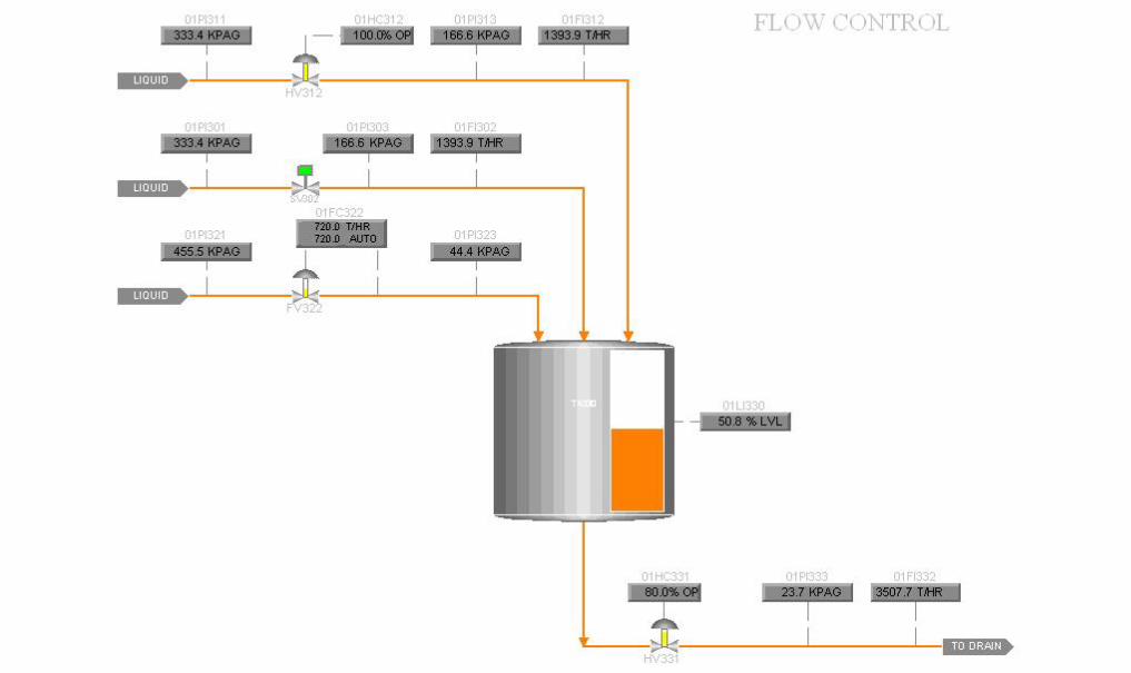
There are three sources of pure water that are controlled by individual valves. Each valve circuit originates from a process source at 500 kPag (73 psig) and 80 ºC (176 ºF). Provision was made to simulate pressure drops from piping losses. These losses have been exaggerated to make them easily recognizable. The three lines empty into a common tank that is drained under the control of a hand operated valve. The solenoid valve (SV302) is a two position valve that is opened and closed by a discrete hand switch (01HS302). The water that passes through this valve drains into a common tank. The hand valve (HV312) is a linear (fully variable) control valve. The valve position is adjusted by an analog output (01HC312). The water that passes through this valve drains into a common tank. The flow control valve (FV322) is a linear (fully variable) control valve. The valve position is adjusted by an auto/manual flow controller (01FC322). The water that passes through this valve drains into a common tank. The tank (TK330) is a simple storage tank that is open to the atmosphere. The volume is 300 m3 (10594.4 ft3) and the cross sectional area is 37.125 m2 (399.6 ft2). The hand valve (HV331) is a linear (fully variable) control valve that controls the flow of water out of the tank. The valve position is adjusted by an analog output (01HC331). After passing through this valve, the water goes to the drain.

Page 14 Honeywell Process Solutions - Guide to Basic Process Equipment and Instrumentation

Control System - Flow Control (Jan 05) Page 15
Control System The following sections describe the instruments and control loops used in the Flow Control model.
Instrumentation
SI Units English Units Tag Description Range Units Range Units
01FC322 Feed Flow 0 - 1440 T/hr 0 - 1585 t/hr 01FI302 Feed Flow 0 - 3600 T/hr 0 - 3964 t/hr 01FI312 Feed Flow 0 - 3600 T/hr 0 - 3964 t/hr 01FI332 Outlet Flow 0 - 4320 T/hr 0 - 4756 t/hr 01HC312 Feed 0 - 100 % 0 - 100 % 01HC331 Feed 0 - 100 % 0 - 100 % 01HS302 Feed Closed - Open - Closed - Open - 01LI330 Tank Level 0 - 100 % 0 - 100 % 01PI301 Feed Pressure 0 - 800 kPag 0 - 116 psig 01PI303 Feed Pressure 0 - 1000 kPag 0 - 145 psig 01PI311 Feed Pressure 0 - 1000 kPag 0 - 145 psig 01PI313 Feed Pressure 0 - 1000 kPag 0 - 145 psig 01PI321 Feed Pressure 0 - 1000 kPag 0 - 145 psig 01PI323 Feed Pressure 0 - 1000 kPag 0 - 145 psig 01PI333 Outlet Pressure 0 - 1000 kPag 0 - 145 psig
A flow indicator (01FI302) displays the flow through the solenoid valve (SV302). Pressure indicators show the supply pressure (01PI301) and downstream pressure (01PI303) around the valve. A flow indicator (01FI312) displays the flow through the hand valve (HV312). Pressure indicators show the supply pressure (01PI311) and downstream pressure (01PI313) around the valve. The PID controller (01FC322) displays the flow through the flow control valve and controls the valve stem position. Supply pressure (01PI321) and downstream pressure (01PI323) around the valve are displayed by pressure indicators. A level indicator (01LI330) displays the level in the tank (TK330). The pressure and flow of the outlet stream following HV331 are shown using the indicators 01PI333 and 01FI332, respectively.
Control Loop
The PID flow controller (01FC322) is a simple reverse acting control loop. It is called a reverse acting controller because a flow higher than the setpoint demands a reduction in the controller output.

Page 16 Honeywell Process Solutions - Guide to Basic Process Equipment and Instrumentation

Operating Procedures - Flow Control (Jan 05) Page 17
Operating Procedures This section describes the cold start and shutdown procedures required to operate the Flow Control model.
Start-Up
Prior to performing a cold start of the model, choose “BTS001” from the Model Selection menu then select the “Newly Configured Model - Initial Conditions” from the Initial Conditions Selection menu. Also, read the “Design Operating Conditions” chapter in this manual for a listing of the cold start plant conditions. The procedure described in the following section represents a typical start-up. UNFREEZE the model and commission RTG. Once in RTG, select "Flow Control" from the title page by clicking on the adjacent button. The display should show three valve circuits, a common collection tank, and an outlet control valve. Each piece of equipment can be controlled by selecting the appropriate faceplate, or by selecting the desired equipment directly from the screen.
1. Open SV302 to initiate flow in that branch. 2. Open HV312 to have an output of 100%. 3. Switch 01FC322 from manual to automatic and put the setpoint at 720 T/hr (792
t/hr). 4. Open HV331 to have an output of 80%.
Shutdown Procedure
Complete the following steps to shutdown the model:
1. Close SV302. 2. Close HV312 by giving it an output of 0%. 3. Close FV322 by putting the controller (01FC322) in manual with an output of 0%.
All water feeds are now closed. 4. Let the tank drain until the level reaches 0%. 5. Close HV331 by giving it an output of 0%.
Other Procedures
This simple flow control system has complete flexibility over the entire operating range. The Trainee may find it beneficial to feed the tank with a single water line and adjust the tank drain to balance the tank level.

Page 18 Honeywell Process Solutions - Guide to Basic Process Equipment and Instrumentation

Design Operating Conditions - Flow Control (Jan 05) Page 19
Design Operating Conditions The following table lists cold start and normal operating conditions. When starting the system from a cold start, assume it has been checked for mechanical completeness. All control valves have been stroked and left in the closed position for fail-closed valves and open for fail-open valves. The normal conditions reflect the 100% operating values. These values are accessible from the BTS001_STEADY snapshot. SI Units English Units
Tag Cold Start Normal Units Cold Start Normal Units 01FC322 0.0 720.0 T/hr 0.0 792.0 t/hr 01FI302 0.0 1394.2 T/hr 0.0 1535.1 t/hr 01FI312 0.0 1394.2 T/hr 0.0 1535.1 t/hr 01FI332 0.0 3508.5 T/hr 0.0 3862.1 t/hr 01HC312 0.0 100.0 % 0.0 100.0 % 01HC331 0.0 80.0 % 0.0 80.0 % 01HS302 Closed Open - Closed Open - 01LI330 0.0 51.0 % 0.0 51.0 % 01PI301 500.0 333.3 kPag 72.5 48.3 psig 01PI303 0.0 166.7 kPag 0.0 24.2 psig 01PI311 500.0 333.3 kPag 72.5 48.3 psig 01PI313 0.0 166.7 kPag 0.0 24.2 psig 01PI321 500.0 455.5 kPag 72.5 66.1 psig 01PI323 0.0 44.4 kPag 0.0 6.4 psig 01PI333 0.0 23.7 kPag 0.0 3.4 psig

Page 20 Honeywell Process Solutions - Guide to Basic Process Equipment and Instrumentation
Instructor Features - Flow Control (Jan 05) Page 21
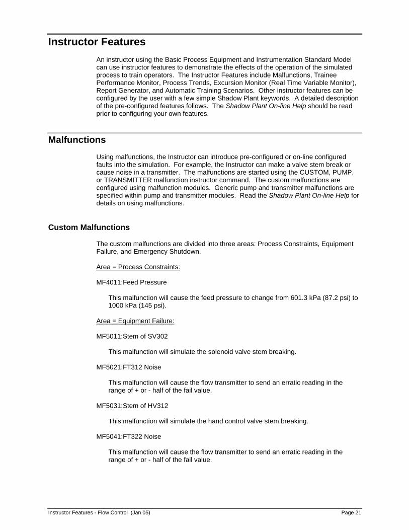
Instructor Features An instructor using the Basic Process Equipment and Instrumentation Standard Model can use instructor features to demonstrate the effects of the operation of the simulated process to train operators. The Instructor Features include Malfunctions, Trainee Performance Monitor, Process Trends, Excursion Monitor (Real Time Variable Monitor), Report Generator, and Automatic Training Scenarios. Other instructor features can be configured by the user with a few simple Shadow Plant keywords. A detailed description of the pre-configured features follows. The Shadow Plant On-line Help should be read prior to configuring your own features.
Malfunctions
Using malfunctions, the Instructor can introduce pre-configured or on-line configured faults into the simulation. For example, the Instructor can make a valve stem break or cause noise in a transmitter. The malfunctions are started using the CUSTOM, PUMP, or TRANSMITTER malfunction instructor command. The custom malfunctions are configured using malfunction modules. Generic pump and transmitter malfunctions are specified within pump and transmitter modules. Read the Shadow Plant On-line Help for details on using malfunctions.
Custom Malfunctions
The custom malfunctions are divided into three areas: Process Constraints, Equipment Failure, and Emergency Shutdown. Area = Process Constraints: MF4011:Feed Pressure
This malfunction will cause the feed pressure to change from 601.3 kPa (87.2 psi) to 1000 kPa (145 psi).
Area = Equipment Failure: MF5011:Stem of SV302
This malfunction will simulate the solenoid valve stem breaking. MF5021:FT312 Noise
This malfunction will cause the flow transmitter to send an erratic reading in the range of + or - half of the fail value.
MF5031:Stem of HV312
This malfunction will simulate the hand control valve stem breaking. MF5041:FT322 Noise
This malfunction will cause the flow transmitter to send an erratic reading in the range of + or - half of the fail value.

Page 22 Honeywell Process Solutions - Guide to Basic Process Equipment and Instrumentation
MF5051:PT323 Noise
This malfunction will cause the pressure transmitter to send an erratic reading in the range of + or - half of the fail value.
MF5061:Stem of FV322
This malfunction will simulate the flow control valve stem breaking. MF5071:Fouling HV312
This malfunction will simulate fouling of the valve to 50% performance. MF5081:Fouling HV331
This malfunction will simulate fouling of the valve to 50% performance. MF5091:FC322 Stuck
This malfunction will cause the controller setpoint to be stuck at 450 T/hr (495.45 t/hr).
Area = Emergency Shutdown: MF6011:Pipe Clog
This will cause the check valve prior to HV331 to become small thus simulating a clogged pipe.
Generic Pump and Transmitter Malfunctions
Although some pump and transmitter malfunctions are pre-configured in the CUSTOM malfunctions, more can be performed using the PUMP and TRANSMITTER malfunction commands. This allows the instructor to on-line configure the versatile pump and transmitter malfunctions.

Instructor Features - Flow Control (Jan 05) Page 23
Monitoring the Training Exercise
Process Trends
All process variables can be used to build trend groups for trend plotting. For more information about the Process Trends, refer to the Shadow Plant On-line Help.
Trainee Performance Tables
Trainee Performance Tables are an on-line configurable tool to assist in the evaluation of a trainee. The tables allow limits to be defined for key process variables. Various methods allow a score to be calculated based on the state of these process variables during an exercise. Please refer to the Shadow Plant On-line Help for more information.
Process Monitor
The process monitor is an on-line configurable feature that highlights selected key process variables. Each variable has a defined target value and calculated deviation from target. Variables which deviate from a specified tolerance are highlighted, allowing the instructor to quickly identify them.
Training Scenarios
The Automatic Training Scenario is an on-line configured instructor feature. This feature allows a programmed sequence of events to be performed automatically to provide repeatable, consistent training. For more information about the Scenario feature, refer to the Shadow Plant On-line Help.

Page 24 Honeywell Process Solutions - Guide to Basic Process Equipment and Instrumentation

Introduction to Level Control (Jan 05) Page 25
Introduction to Level Control Level control is very important in the process industry. It is used for many purposes including maintaining and controlling material and product inventories, maintaining optimum operating conditions, and avoiding equipment damage. This model will provide an opportunity to operate a typical level control application and show how the instrumentation and control devices are accessed and utilized from a control display.
Model Capabilities
This process model is intended to familiarize operator trainees with the basic concepts of instrumentation and control. There is a hand control valve, and a level control valve, and a centrifugal pump to assist in emptying the tank. The trainee must operate these in collaboration or the liquid receiver tank will either empty or overflow.
Unit Description
A water source is fed under operator control to a tank. The operator must control the flow into and out of the tank to keep it from running dry or overflowing.
Control Scheme
There is one Level Controller, 01LC402. All remaining control is manual, under operator control.

Page 26 Honeywell Process Solutions - Guide to Basic Process Equipment and Instrumentation

Process Description - Level Control (Jan 05) Page 27
Process Description
Process Equipment
The following table lists the process equipment used in the Level Control model of the Basic Process Equipment and Instrumentation Standard Model:
Tag Description HV401 Hand Valve LV402 Level Control Valve P403 Centrifugal Pump TK402 Tank
Process Flow
There is one source of pure water controlled by a valve. The valve circuit originates from a process source at 200 kPag (29 psig) and 25ºC (77 ºF). Provision was made to simulate pressure drops from piping losses. These losses have been exaggerated to make them easily recognizable. The process line empties into a tank that is drained under the control of a level control valve. The hand valve (HV401) is a linear (fully variable) control valve. The valve position is adjusted by an analog output (01HC401). The water that passes through this valve drains into the tank (TK402). The tank (TK402) is a simple storage tank that is open to the atmosphere. The volume is 30 m3 (1059.4 ft3) and the cross sectional area is 4.95 m2 (53.3 ft2). The centrifugal pump (P403) aids in the emptying of the tank (TK402). A minimum pressure is required at the pump inlet to prevent cavitation. This pressure corresponds to a 5% level in the tank. If the tank level falls below 5%, a pump interlock is activated causing the pump to shut down. The level control valve (LV402) is a linear (fully variable) control valve. The valve position is adjusted by an auto/manual level controller (01LC402). The water that passes through this valve goes to the drain.

Page 28 Honeywell Process Solutions - Guide to Basic Process Equipment and Instrumentation
Control System - Level Control (Jan 05) Page 29
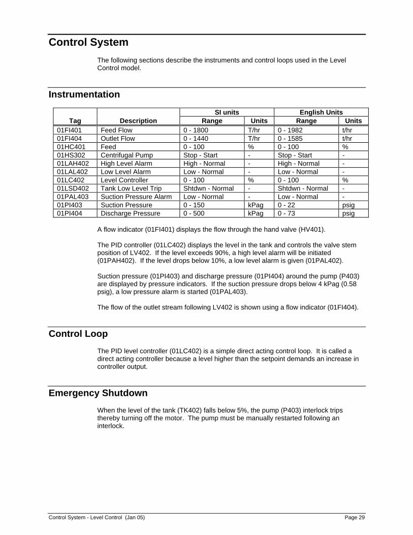
Control System The following sections describe the instruments and control loops used in the Level Control model.
Instrumentation
SI units English Units Tag Description Range Units Range Units
01FI401 Feed Flow 0 - 1800 T/hr 0 - 1982 t/hr 01FI404 Outlet Flow 0 - 1440 T/hr 0 - 1585 t/hr 01HC401 Feed 0 - 100 % 0 - 100 % 01HS302 Centrifugal Pump Stop - Start - Stop - Start - 01LAH402 High Level Alarm High - Normal - High - Normal - 01LAL402 Low Level Alarm Low - Normal - Low - Normal - 01LC402 Level Controller 0 - 100 % 0 - 100 % 01LSD402 Tank Low Level Trip Shtdwn - Normal - Shtdwn - Normal - 01PAL403 Suction Pressure Alarm Low - Normal - Low - Normal - 01PI403 Suction Pressure 0 - 150 kPag 0 - 22 psig 01PI404 Discharge Pressure 0 - 500 kPag 0 - 73 psig
A flow indicator (01FI401) displays the flow through the hand valve (HV401). The PID controller (01LC402) displays the level in the tank and controls the valve stem position of LV402. If the level exceeds 90%, a high level alarm will be initiated (01PAH402). If the level drops below 10%, a low level alarm is given (01PAL402). Suction pressure (01PI403) and discharge pressure (01PI404) around the pump (P403) are displayed by pressure indicators. If the suction pressure drops below 4 kPag (0.58 psig), a low pressure alarm is started (01PAL403). The flow of the outlet stream following LV402 is shown using a flow indicator (01FI404).
Control Loop
The PID level controller (01LC402) is a simple direct acting control loop. It is called a direct acting controller because a level higher than the setpoint demands an increase in controller output.
Emergency Shutdown
When the level of the tank (TK402) falls below 5%, the pump (P403) interlock trips thereby turning off the motor. The pump must be manually restarted following an interlock.

Page 30 Honeywell Process Solutions - Guide to Basic Process Equipment and Instrumentation

Operating Procedures - Level Control (Jan 05) Page 31
Operating Procedures This section describes the cold start and shutdown procedures required to operate the Level Control model.
Start-Up
Prior to performing a cold start of the model, choose “BTS001” from the Model Selection menu then select the “Newly Configured Model - Initial Conditions” from the Initial Conditions Selection menu. Also, read the “Design Operating Conditions” chapter in this manual for a listing of the cold start plant conditions. The procedure described in the following section represents a typical start-up. UNFREEZE the model and commission RTG. Once in RTG, select "Level Control" from the title page by clicking on the adjacent button. The display should show a valve circuit, a tank, and a level control valve. Each piece of equipment can be controlled by selecting the appropriate faceplate, or by selecting the desired equipment directly from the screen.
1. Open the hand valve (HV401) so the output is 90% thus initiating flow through the system.
2. Switch 01LC402 from manual to automatic and put the setpoint at 50%. 3. Start the pump (P403) once the level in the tank (TK402) is greater than 5%.
Shutdown Procedure
Complete the following steps to shutdown the model:
1. Close HV401 by giving it an output of 0%. This shuts off the feed source. 2. Drain the tank by setting the setpoint of 01LC402 at 10%. After this level is
achieved, switch the controller to MANUAL and decrease the level to 5%. The tank cannot be drained to less than 5% level as the pump motor interlock will trip.
3. Once the level in the tank reaches 5%, stop the pump. 4. Give 01LC402 an output of 0%.
Other Procedures
The simple level control system has complete flexibility over the entire operating range. The Trainee may find it beneficial to feed the tank at different rates and adjust the controller tuning constants to achieve the best response for the tank level.

Page 32 Honeywell Process Solutions - Guide to Basic Process Equipment and Instrumentation

Design Operating Conditions - Level Control (Jan 05) Page 33
Design Operating Conditions The following table lists cold start and normal operating conditions. When starting the system from a cold start, assume it has been checked for mechanical completeness. All control valves have been stroked and left in the closed position for fail-closed valves and open for fail-open valves. The normal conditions reflect the 100% operating values. These values are accessible from the BTS001_STEADY snapshot.
SI Units English Units Tag Cold Start Normal Units Cold Start Normal Units
01FI401 0.0 412.4 T/hr 0.0 454.0 t/hr 01FI404 0.0 412.4 T/hr 0.0 454.0 t/hr 01HC401 0.0 90.0 % 0.0 90.0 % 01HS403 Stop Start - Stop Start - 01LAH402 Normal Normal - Normal Normal - 01LAL402 Low Normal - LOW NORMAL - 01LC402 0.0 50.0 % 0.0 50.0 % 01LSD402 Shtdwn Normal - Shtdwn Normal - 01PAL403 Low Normal - Low Normal - 01PI403 29.8 29.8 kPag 4.31550 4.31550 psig 01PI404 0.0 361.8 kPag 0.0 52.5 psig

Page 34 Honeywell Process Solutions - Guide to Basic Process Equipment and Instrumentation

Instructor Features - Level Control (Jan 05) Page 35
Instructor Features An instructor using the Basic Process Equipment and Instrumentation Standard Model can use instructor features to demonstrate the effects of the operation of the simulated process to train operators. The Instructor Features include Malfunctions, Trainee Performance Monitor, Process Trends, Excursion Monitor (Real Time Variable Monitor), Report Generator, and Automatic Training Scenarios. Other instructor features can be configured by the user with a few simple Shadow Plant keywords. A detailed description of the pre-configured features follows. The Shadow Plant On-line Help should be read prior to configuring your own features.
Malfunctions
Using malfunctions, the Instructor can introduce pre-configured or on-line configured faults into the simulation. For example, the Instructor can make a valve stem break or cause noise in a transmitter. The malfunctions are started using the CUSTOM, PUMP, or TRANSMITTER malfunction instructor command. The custom malfunctions are configured using malfunction modules. Generic pump and transmitter malfunctions are specified within pump and transmitter modules. Read the Shadow Plant On-line Help for details on using malfunctions.
Custom Malfunctions
The custom malfunctions are divided into three areas: Process Constraints, Equipment Failure, and Emergency Shutdown. Area = Process Constraints:
MF4012:Feed Pressure
This malfunction will cause the feed pressure to change from 301.3 kPa (43.7 psi) to 1000 kPa (145 psi).
Area = Equipment Failure:
MF5012:P403 Fail
This malfunction will cause the pump to fail.
MF5022:FT401 Noise
This malfunction will cause the flow transmitter to send an erratic reading in the range of + or - half of the fail value.
MF5032:LT402 Noise
This malfunction will cause the level transmitter to send an erratic reading in the range of + or - half of the fail value.

Page 36 Honeywell Process Solutions - Guide to Basic Process Equipment and Instrumentation
MF5042:PT403 Noise
This malfunction will cause the pressure transmitter to send an erratic reading in the range of + or - half of the fail value.
MF5052:Stem of LV402
This malfunction will simulate the level control valve stem breaking.
MF5062:Fouling of HV401
This malfunction will simulate fouling of the valve to 50% performance.
MF5072:PAL403 Low Alm
This malfunction will cause an erroneous low alarm.
MF5082:LC402 Stuck
This malfunction will cause the controller setpoint to be stuck at 75%.
Area = Emergency Shutdown:
MF6012:Pipe Clog
This will cause the valve to become small thus simulating a clogged pipe.
Generic Pump and Transmitter Malfunctions
Although some pump and transmitter malfunctions are pre-configured in the CUSTOM malfunctions, more can be performed using the PUMP and TRANSMITTER malfunction commands. This allows the instructor to on-line configure the versatile pump and transmitter malfunctions.
Trainee Performance Monitor
The variables of the following points are monitored when a certain event takes place. This allows the instructor to select a number of key variables that are desirable when testing a trainee in the event of a malfunction. The logging of statistics continues until the event is ended. The variables are logged every four (4) seconds.
Event Points Variables TK402 High Level 01FI401 Feed Flow 01LI402 TK402 Tank Level 01FI404 Outlet Flow P403 Low Suct. Press. 01FI401 Feed Flow
01LI402 TK402 Tank Level 01PI403 Suction Pressure 01FI404 Outlet Flow
Instructor Features - Level Control (Jan 05) Page 37
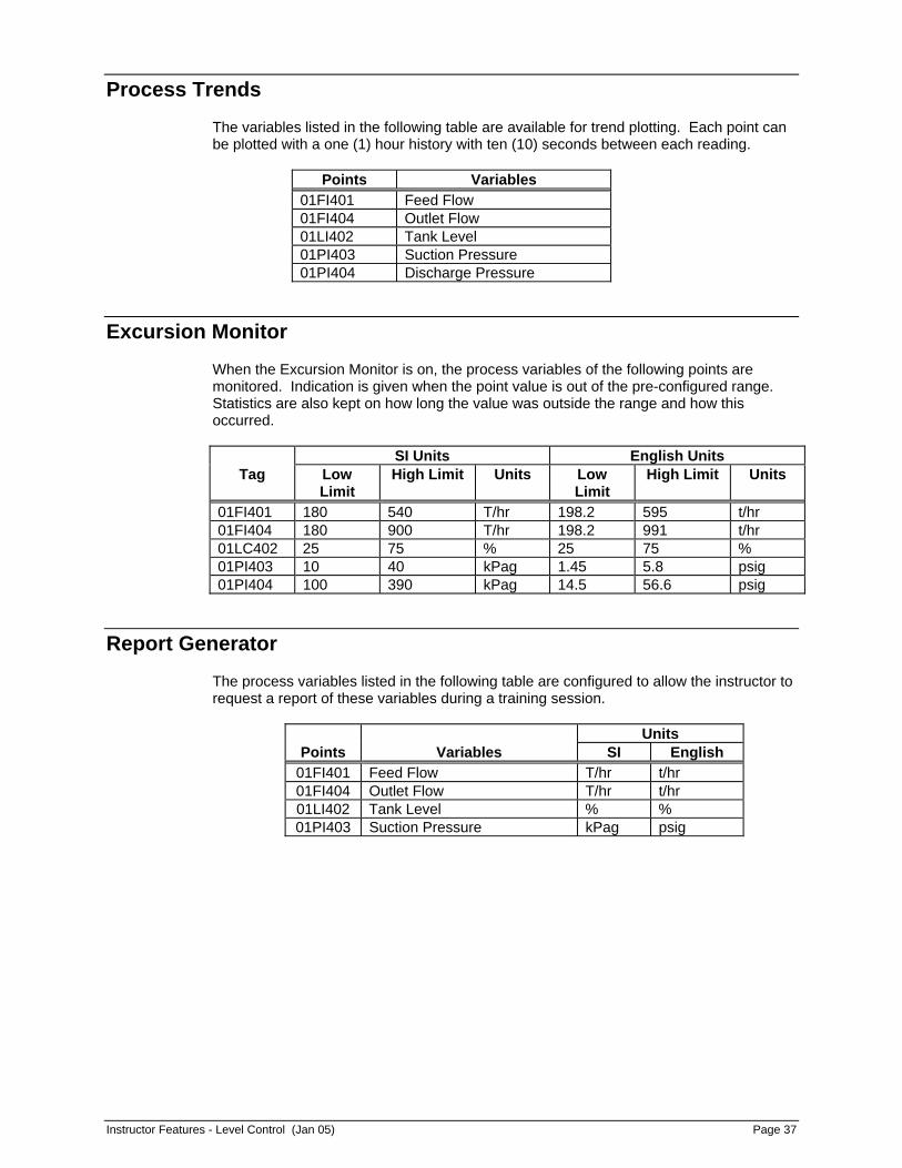
Process Trends
The variables listed in the following table are available for trend plotting. Each point can be plotted with a one (1) hour history with ten (10) seconds between each reading.
Points Variables 01FI401 Feed Flow 01FI404 Outlet Flow 01LI402 Tank Level 01PI403 Suction Pressure 01PI404 Discharge Pressure
Excursion Monitor
When the Excursion Monitor is on, the process variables of the following points are monitored. Indication is given when the point value is out of the pre-configured range. Statistics are also kept on how long the value was outside the range and how this occurred.
SI Units English Units Tag Low
Limit High Limit Units Low
Limit High Limit Units
01FI401 180 540 T/hr 198.2 595 t/hr 01FI404 180 900 T/hr 198.2 991 t/hr 01LC402 25 75 % 25 75 % 01PI403 10 40 kPag 1.45 5.8 psig 01PI404 100 390 kPag 14.5 56.6 psig
Report Generator
The process variables listed in the following table are configured to allow the instructor to request a report of these variables during a training session.
Units Points Variables SI English
01FI401 Feed Flow T/hr t/hr 01FI404 Outlet Flow T/hr t/hr 01LI402 Tank Level % % 01PI403 Suction Pressure kPag psig

Page 38 Honeywell Process Solutions - Guide to Basic Process Equipment and Instrumentation

Introduction to Pressure Control (Jan 05) Page 39
Introduction to Pressure Control Pressure control of gas streams is similar to level control for liquid streams. If there is more gas going into a vessel than is being removed, the pressure increases. This model will concentrate on the elements of flow and pressure control encountered in processes, and how the instrumentation and control devices are accessed and utilized from a control display.
Model Capabilities
This process model is intended to familiarize operator trainees with the basic concepts of instrumentation and control. There is a solenoid valve, hand control valve, and a pressure control valve. The trainee must operate these in collaboration or the pressure within the vessel will become too high and trigger the pressure relief valve.
Unit Description
A methane (CH4) source is fed under operator control to a pressure vessel. The operator must control the flow into and out of the vessel to maintain an operating pressure within the vessel.
Control Scheme
There is one Pressure Controller, 01PC503. All remaining control is manual, under operator control.

Page 40 Honeywell Process Solutions - Guide to Basic Process Equipment and Instrumentation
Process Description - Pressure Control (Jan 05) Page 41
Process Description
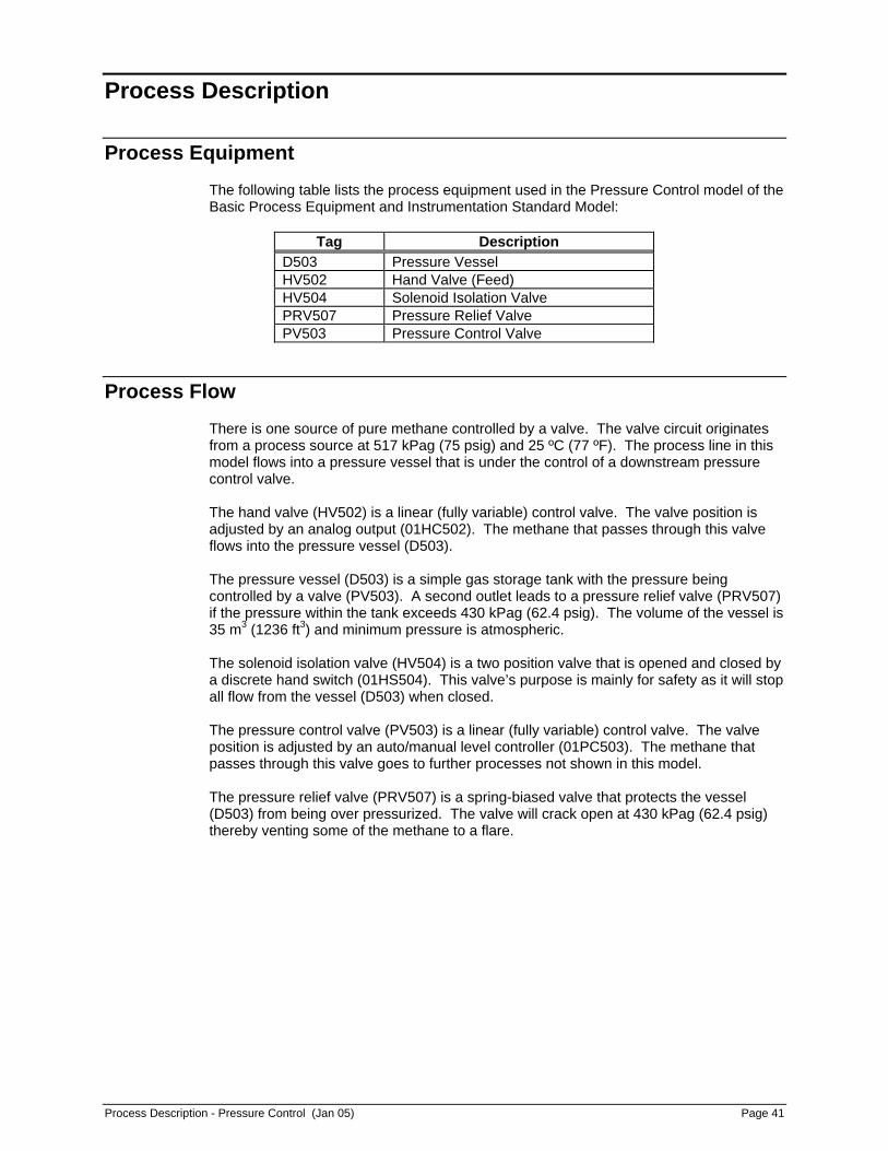
Process Equipment
The following table lists the process equipment used in the Pressure Control model of the Basic Process Equipment and Instrumentation Standard Model:
Tag Description D503 Pressure Vessel HV502 Hand Valve (Feed) HV504 Solenoid Isolation Valve PRV507 Pressure Relief Valve PV503 Pressure Control Valve
Process Flow
There is one source of pure methane controlled by a valve. The valve circuit originates from a process source at 517 kPag (75 psig) and 25 ºC (77 ºF). The process line in this model flows into a pressure vessel that is under the control of a downstream pressure control valve. The hand valve (HV502) is a linear (fully variable) control valve. The valve position is adjusted by an analog output (01HC502). The methane that passes through this valve flows into the pressure vessel (D503). The pressure vessel (D503) is a simple gas storage tank with the pressure being controlled by a valve (PV503). A second outlet leads to a pressure relief valve (PRV507) if the pressure within the tank exceeds 430 kPag (62.4 psig). The volume of the vessel is 35 m3 (1236 ft3) and minimum pressure is atmospheric. The solenoid isolation valve (HV504) is a two position valve that is opened and closed by a discrete hand switch (01HS504). This valve’s purpose is mainly for safety as it will stop all flow from the vessel (D503) when closed. The pressure control valve (PV503) is a linear (fully variable) control valve. The valve position is adjusted by an auto/manual level controller (01PC503). The methane that passes through this valve goes to further processes not shown in this model. The pressure relief valve (PRV507) is a spring-biased valve that protects the vessel (D503) from being over pressurized. The valve will crack open at 430 kPag (62.4 psig) thereby venting some of the methane to a flare.

Page 42 Honeywell Process Solutions - Guide to Basic Process Equipment and Instrumentation

Control System - Pressure Control (Jan 05) Page 43
Control System The following sections describe the instruments and control loops used in the Pressure Control model.
Instrumentation
SI Units English Units Tag Description Range Units Range Units
01FI502 Feed Flow 0 - 18 T/hr 0 - 20 t/hr 01FI504 Outlet Flow 0 - 18 T/hr 0 - 20 t/hr 01HC502 Feed 0 - 100 % 0 - 100 % 01HS504 Isolation Valve Closed - Open - Closed - Open - 01PAH503 Vessel Pressure Alarm High - Normal - High - Normal - 01PC503 Pressure Controller 0 - 600 kPag 0 - 87 psig 01PI501 Feed Pressure 0 - 1000 kPag 0 - 145 psig 01PI505 Outlet Pressure 0 - 600 kPag 0 - 87 psig
A flow indicator (01FI502) displays the feed flow through the hand valve (HV502). The flow of the outlet stream following PV503 is shown using the flow indicator (01FI504). An analog output (01HC502) controls the valve stem position of HV502. A discrete handswitch (01HS504) opens and closes HV504. The PID controller (01PC503) displays the pressure in the vessel and controls the valve stem position of PV503. If the pressure exceeds 390 kPag (56.6 psig), a high pressure alarm will be initiated (01PAH503). Feed pressure (01PI501) and outlet pressure (01PI505) are displayed by pressure indicators.
Control Loop
The PID pressure controller (01PC503) is a simple direct acting control loop. It is called a direct acting controller because a pressure higher than the setpoint demands an increase in controller output.

Page 44 Honeywell Process Solutions - Guide to Basic Process Equipment and Instrumentation
Operating Procedures - Pressure Control (Jan 05) Page 45
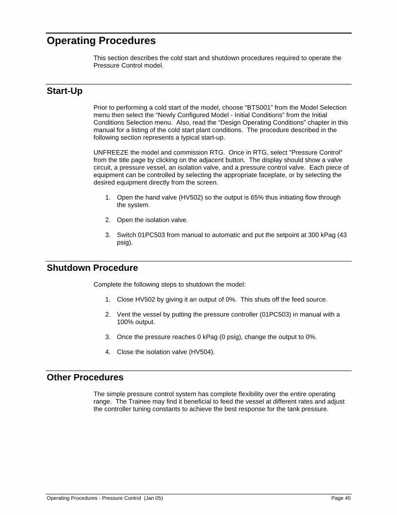
Operating Procedures This section describes the cold start and shutdown procedures required to operate the Pressure Control model.
Start-Up
Prior to performing a cold start of the model, choose “BTS001” from the Model Selection menu then select the “Newly Configured Model - Initial Conditions” from the Initial Conditions Selection menu. Also, read the “Design Operating Conditions” chapter in this manual for a listing of the cold start plant conditions. The procedure described in the following section represents a typical start-up. UNFREEZE the model and commission RTG. Once in RTG, select "Pressure Control" from the title page by clicking on the adjacent button. The display should show a valve circuit, a pressure vessel, an isolation valve, and a pressure control valve. Each piece of equipment can be controlled by selecting the appropriate faceplate, or by selecting the desired equipment directly from the screen.
1. Open the hand valve (HV502) so the output is 65% thus initiating flow through the system.
2. Open the isolation valve. 3. Switch 01PC503 from manual to automatic and put the setpoint at 300 kPag (43
psig).
Shutdown Procedure
Complete the following steps to shutdown the model:
1. Close HV502 by giving it an output of 0%. This shuts off the feed source. 2. Vent the vessel by putting the pressure controller (01PC503) in manual with a
100% output. 3. Once the pressure reaches 0 kPag (0 psig), change the output to 0%. 4. Close the isolation valve (HV504).
Other Procedures
The simple pressure control system has complete flexibility over the entire operating range. The Trainee may find it beneficial to feed the vessel at different rates and adjust the controller tuning constants to achieve the best response for the tank pressure.

Page 46 Honeywell Process Solutions - Guide to Basic Process Equipment and Instrumentation

Design Operating Conditions - Pressure Control (Jan 05) Page 47
Design Operating Conditions The following table lists cold start and normal operating conditions. When starting the system from a cold start, assume it has been checked for mechanical completeness. All control valves have been stroked and left in the closed position for fail-closed valves and open for fail-open valves. The normal conditions reflect the 100% operating values. These values are accessible from the BTS001_STEADY snapshot.
SI Units English Units Tag Cold Start Normal Units Cold Start Normal Units
01FI502 0.0 2.5 T/hr 0.0 2.8 t/hr 01FI504 0.0 2.5 T/hr 0.0 2.8 t/hr 01HC502 0.0 65.0 % 0.0 65.0 % 01HS504 Closed Open - Closed Open - 01PAH503 Normal Normal - Normal Normal - 01PC503 0.0 300.0 kPag 0.0 43.0 psig 01PI501 516.8 436.8 kPag 75.0 63.2 psig 01PI505 0.0 159.5 kPag 0.0 23.2 psig

Page 48 Honeywell Process Solutions - Guide to Basic Process Equipment and Instrumentation

Instructor Features - Pressure Control (Jan 05) Page 49
Instructor Features An instructor using the Basic Process Equipment and Instrumentation Standard Model can use instructor features to demonstrate the effects of the operation of the simulated process to train operators. The Instructor Features include Malfunctions, Trainee Performance Monitor, Process Trends, Excursion Monitor (Real Time Variable Monitor), Report Generator, and Automatic Training Scenarios. Other instructor features can be configured by the user with a few simple Shadow Plant keywords. A detailed description of the pre-configured features follows. The Shadow Plant On-line Help should be read prior to configuring your own features.
Malfunctions
Using malfunctions, the Instructor can introduce pre-configured or on-line configured faults into the simulation. For example, the Instructor can make a valve stem break or cause noise in a transmitter. The malfunctions are started using the CUSTOM, PUMP, or TRANSMITTER malfunction instructor command. The custom malfunctions are configured using malfunction modules. Generic pump and transmitter malfunctions are specified within pump and transmitter modules. Read the Shadow Plant On-line Help for details on using malfunctions.
Custom Malfunctions
The custom malfunctions are divided into three areas: Process Constraints, Equipment Failure, and Emergency Shutdown. Area = Process Constraints:
MF4013:Feed Temp
This malfunction will cause the feed to change from 25 ºC (77 ºF) to 100 ºC (212 ºF).
Area = Equipment Failure:
MF5013:PT503 Noise
This malfunction will cause the pressure transmitter to send an erratic reading in the range of + or - half of the fail value.
MF5023:Stem of HV502
This malfunction will simulate the supply valve stem breaking.
MF5033:Stem of HV504
This malfunction will simulate the block valve stem breaking.
MF5043:Fail PRV507
This malfunction will cause the pressure relief valve to be stuck 100% open.

Page 50 Honeywell Process Solutions - Guide to Basic Process Equipment and Instrumentation
MF5053:Stem of PV503
This malfunction will cause the discharge valve to fail.
MF5063:Fouling of PV503
This malfunction will simulate fouling of the valve to 50% performance.
Area = Emergency Shutdown:
MF6013:Out Pipe Clog
This will cause the outlet check valve to have a Cv equal to zero thus simulating a clogged pipe.
MF6023:Rel Pipe Clog
This malfunction will cause the Cv of the check valve prior to the relief valve to be zero thus simulating a clogged pipe.
NOTE: The Emergency Shutdown malfunctions are designed to operate in conjunction
with each other, therefore, both must be enabled to cause an emergency shutdown situation.
Generic Pump and Transmitter Malfunctions
Although some pump and transmitter malfunctions are pre-configured in the CUSTOM malfunctions, more can be performed using the PUMP and TRANSMITTER malfunction commands. This allows the instructor to on-line configure the versatile pump and transmitter malfunctions.
Monitoring the Training Exercise
Process Trends
All process variables can be used to build trend groups for trend plotting. For more information about the Process Trends, refer to the Shadow Plant On-line Help.
Trainee Performance Tables
Trainee Performance Tables are an on-line configurable tool to assist in the evaluation of a trainee. The tables allow limits to be defined for key process variables. Various methods allow a score to be calculated based on the state of these process variables during an exercise. Please refer to the Shadow Plant On-line Help for more information.
Process Monitor
The process monitor is an on-line configurable feature that highlights selected key process variables. Each variable has a defined target value and calculated deviation from target. Variables which deviate from a specified tolerance are highlighted, allowing the instructor to quickly identify them.

Instructor Features - Pressure Control (Jan 05) Page 51
Training Scenarios
The Automatic Training Scenario is an on-line configured instructor feature. This feature allows a programmed sequence of events to be performed automatically to provide repeatable, consistent training. For more information about the Scenario feature, refer to the Shadow Plant On-line Help.

Page 52 Honeywell Process Solutions - Guide to Basic Process Equipment and Instrumentation

Introduction to Pump Control (Jan 05) Page 53
Introduction to Pump Control This model will concentrate on a typical centrifugal pump application and how the instrumentation and control devices are accessed and utilized from a control display.
Model Capabilities
This process model is intended to familiarize operator trainees with the basic concepts of instrumentation and control. There are two hand control valves, a centrifugal pump, a flow control valve, and a level controller. The trainee must operate these in collaboration so the liquid receiver tank does not overflow. The other consideration is pump cavitation due to insufficient flow.
Unit Description
A source of pure water is fed under operator control to a tank. A recycle stream is fed back to the tank to maintain the pump load. The operator must control the flow into and out of the tank to keep the tank from running dry or overflowing.
Control Scheme
There is a Flow Controller, 01FC108 and a Level Controller, 01LC108, that work together in a cascade control loop. All remaining control is manual, under operator control.

Page 54 Honeywell Process Solutions - Guide to Basic Process Equipment and Instrumentation
Process Description - Pump Control (Jan 05) Page 55
Process Description
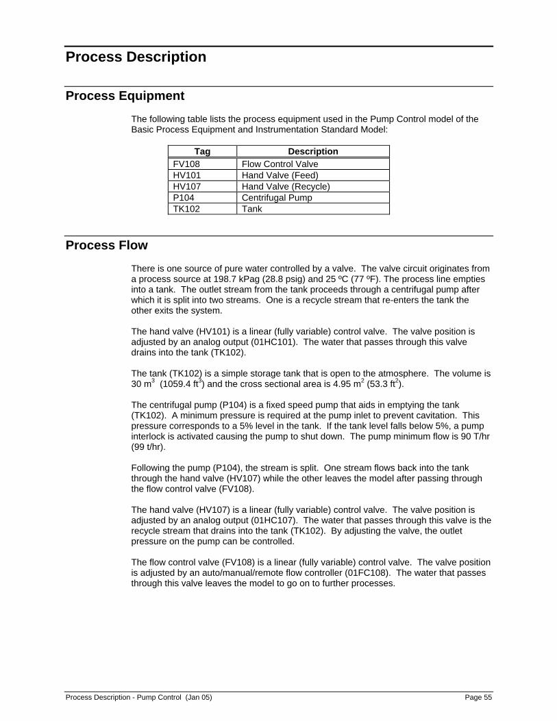
Process Equipment
The following table lists the process equipment used in the Pump Control model of the Basic Process Equipment and Instrumentation Standard Model:
Tag Description FV108 Flow Control Valve HV101 Hand Valve (Feed) HV107 Hand Valve (Recycle) P104 Centrifugal Pump TK102 Tank
Process Flow
There is one source of pure water controlled by a valve. The valve circuit originates from a process source at 198.7 kPag (28.8 psig) and 25 ºC (77 ºF). The process line empties into a tank. The outlet stream from the tank proceeds through a centrifugal pump after which it is split into two streams. One is a recycle stream that re-enters the tank the other exits the system. The hand valve (HV101) is a linear (fully variable) control valve. The valve position is adjusted by an analog output (01HC101). The water that passes through this valve drains into the tank (TK102). The tank (TK102) is a simple storage tank that is open to the atmosphere. The volume is 30 m3 (1059.4 ft3) and the cross sectional area is 4.95 m2 (53.3 ft2). The centrifugal pump (P104) is a fixed speed pump that aids in emptying the tank (TK102). A minimum pressure is required at the pump inlet to prevent cavitation. This pressure corresponds to a 5% level in the tank. If the tank level falls below 5%, a pump interlock is activated causing the pump to shut down. The pump minimum flow is 90 T/hr (99 t/hr). Following the pump (P104), the stream is split. One stream flows back into the tank through the hand valve (HV107) while the other leaves the model after passing through the flow control valve (FV108). The hand valve (HV107) is a linear (fully variable) control valve. The valve position is adjusted by an analog output (01HC107). The water that passes through this valve is the recycle stream that drains into the tank (TK102). By adjusting the valve, the outlet pressure on the pump can be controlled. The flow control valve (FV108) is a linear (fully variable) control valve. The valve position is adjusted by an auto/manual/remote flow controller (01FC108). The water that passes through this valve leaves the model to go on to further processes.

Page 56 Honeywell Process Solutions - Guide to Basic Process Equipment and Instrumentation

Control System - Pump Control (Jan 05) Page 57
Control System The following sections describe the instruments and control loops used in the Pump Control model.
Instrumentation
SI Units English Units Tag Description Range Units Range Units
01FAL105 Flow Alarm Low - Normal - Low - Normal - 01FC108 Flow Controller 0 - 720 T/hr 0 - 793 t/hr 01FI105 Pump Discharge Flow 0 - 720 T/hr 0 - 793 t/hr 01HC101 Feed 0 - 100 % 0 - 100 % 01HC107 Recycle 0 - 100 % 0 - 100 % 01HS104 Centrifugal Pump Stop - Start - Stop - Start - 01IAH104 Pump Load Alarm High - Normal - High - Normal - 01II104 Motor Load 0 - 200 Amps 0 - 200 Amps 01LAH108 Level Alarm High - Normal - High - Normal - 01LAL108 Level Alarm Low - Normal - Low - Normal - 01LC108 Level Controller 0 - 100 % 0 - 100 % 01LSD108 Tank Low Level Trip Shtdwn - Normal - Shtdwn - Normal - 01PAH105 Discharge Pressure Alarm High - Normal - High - Normal - 01PAL103 Suction Pressure Alarm Low - Normal - Low - Normal - 01PI103 Suction Pressure 0 - 200 kPag 0 - 29 psig 01PI105 Discharge Pressure 0 - 500 kPag 0 - 73 psig
The flow alarm (01FAL105) indicates if the discharge flow from the pump (P104) is below 30 T/hr (66 t/hr). The PID controller (01FC108) displays the flow through the valve (FV108) and controls the valve stem position. A flow indicator (01FI105) displays the discharge flow from the pump (P104). Analog outputs (01HC101, 01HC107) control the valve stem positions of HV101 and HV107, respectively. A discrete handswitch (01HS104) starts and stops the pump, P104. A pump load indicator (01II104) displays the current being used by the pump (P104) while the pump load alarm (01IAH104) indicates when the load exceeds 90% of the maximum. The PID controller (01LC108) displays the level in the tank and is the master control for the flow controller (01FC108). If the level exceeds 90%, a high level alarm will be initiated (01LAH108). If the level drops below 10%, a low level alarm is given (01LAL108). If the level drops below 5%, the tank low level trip (01LSD108) shuts down the pump (P104). Suction pressure (01PI103) and discharge pressure (01PI105) around the pump (P403) are displayed by pressure indicators. If the suction pressure drops below 4 kPag (0.58 psig), a low pressure alarm is started (01PAL103). A high pressure alarm (01PAH105) indicates if the discharge pressure rises above 380 kPag (55.1 psig).

Page 58 Honeywell Process Solutions - Guide to Basic Process Equipment and Instrumentation
Control Loop
The PID level controller (01LC108) is a simple direct acting control loop. It is called a direct acting controller because a level higher than the setpoint demands an increase in controller output. The PID flow controller (01FC108) is a simple reverse acting control loop. It is called a reverse acting controller because a flow higher than the setpoint demands a reduction in the controller output.
Emergency Shutdown
When the level of the tank (TK102) falls below 5%, the pump (P403) interlock trips thereby turning off the motor. The pump must be manually restarted following an interlock.

Operating Procedures - Pump Control (Jan 05) Page 59
Operating Procedures This section describes the cold start and shutdown procedures required to operate the Pump Control model.
Start-Up
Prior to performing a cold start of the model, choose “BTS001” from the Model Selection menu then select the “Newly Configured Model - Initial Conditions” from the Initial Conditions Selection menu. Also, read the “Design Operating Conditions” chapter in this manual for a listing of the cold start plant conditions. The procedure described in the following section represents a typical start-up. UNFREEZE the model and commission RTG. Once in RTG, select "Pump Control" from the title page by clicking on the adjacent button. The display should show a valve circuit, a receiving tank, a centrifugal pump, a recycle valve, a flow control valve. Each piece of equipment can be controlled by selecting the appropriate faceplate, or by selecting the desired equipment directly from the screen.
1. Open the hand valve (HV101) so the output is 71% thus initiating flow through the system.
2. Start the pump (P104). 3. Open the hand valve (HV107) so the output is 50% thus initiating the recycle flow
and the pump minimum required flow. 4. Switch the level controller, 01LC108, from manual to automatic. 5. Give the flow controller, 01FC108, an output of 50%. 6. Once flow has been initiated, switch 01FC108 from manual to automatic and
finally to remote (RSP). 7. Give 01LC108 a setpoint of 50%
Shutdown Procedure
Complete the following steps to shutdown the model: 1. Close HV101 by giving it an output of 0%. This shuts off the feed source. 2. Close HV107 by giving it an output of 0%. This shuts off the recycle. 3. Drain the tank by setting the setpoint of 01LC108 at 10%. After this level is
achieved, switch the controller to MANUAL and decrease the level to 5%. The tank cannot be drained to less than 5% level as the pump motor interlock will trip.
4. Once the level in the tank reaches 5%, stop the pump. 5. Put both controllers in manual with a 0% output.
Page 60 Honeywell Process Solutions - Guide to Basic Process Equipment and Instrumentation
Other Procedures
The simple pump control system has complete flexibility over the entire operating range. The Trainee may find it beneficial to feed the vessel at different rates and adjust the controller tuning constants to achieve the best response for the tank level.

Design Operating Conditions - Pump Control (Jan 05) Page 61
Design Operating Conditions The following table lists cold start and normal operating conditions. When starting the system from a cold start, assume it has been checked for mechanical completeness. All control valves have been stroked and left in the closed position for fail-closed valves and open for fail-open valves. The normal conditions reflect the 100% operating values. These values are accessible from the BTS001_STEADY snapshot.
SI Units English Units Tag Cold Start Normal Units Cold Start Normal Units
01FAL105 Low Normal - Low Normal - 01FC108 0.0 360.3 T/hr 0.0 396.7 t/hr 01FI105 0.0 462.6 T/hr 0.0 509.3 t/hr 01HC101 0.0 71.0 % 0.0 71.0 % 01HC107 0.0 50.0 % 0.0 50.0 % 01HS104 Stop Start - Stop Start - 01IAH104 Normal Normal - Normal Normal - 01II104 0.0 102.1 Amps 0.0 102.1 Amps 01LAH108 Normal Normal - Normal Normal - 01LAL108 Low Normal - Low Normal - 01LC108 0.0 50.0 % 0.0 50.0 % 01LSD108 Shtdwn Normal - Shtdwn Normal - 01PAH105 Normal Normal - Normal Normal - 01PAL103 Low Normal - Low Normal - 01PI103 29.8 29.8 kPag 4.31550 4.3 psig 01PI105 0.0 359.1 kPag 0.0 52.1 psig

Page 62 Honeywell Process Solutions - Guide to Basic Process Equipment and Instrumentation

Instructor Features - Pump Control (Jan 05) Page 63
Instructor Features An instructor using the Basic Process Equipment and Instrumentation Standard Model can use instructor features to demonstrate the effects of the operation of the simulated process to train operators. The Instructor Features include Malfunctions, Trainee Performance Monitor, Process Trends, Excursion Monitor (Real Time Variable Monitor), Report Generator, and Automatic Training Scenarios. Other instructor features can be configured by the user with a few simple Shadow Plant keywords. A detailed description of the pre-configured features follows. The Shadow Plant On-line Help should be read prior to configuring your own features.
Malfunctions
Using malfunctions, the Instructor can introduce pre-configured or on-line configured faults into the simulation. For example, the Instructor can make a valve stem break or cause noise in a transmitter. The malfunctions are started using the CUSTOM, PUMP, or TRANSMITTER malfunction instructor command. The custom malfunctions are configured using malfunction modules. Generic pump and transmitter malfunctions are specified within pump and transmitter modules. Read the Shadow Plant On-line Help for details on using malfunctions.
Custom Malfunctions
The custom malfunctions are divided into three areas: Process Constraints, Equipment Failure, and Emergency Shutdown. Area = Process Constraints:
MF4014:Out Pressure
This will cause the outlet pressure to change from 101.3 kPa (14.7 psi) to 500 kPa (72.5 psi).
Area = Equipment Failure:
MF5014:P104 Fail
This malfunction will cause the pump to fail.
MF5024:LT108 Noise
This malfunction will cause the level transmitter to send an erratic reading in the range of + or - half of the fail value.
MF5034:PT103 Noise
This malfunction will cause the pressure transmitter to send an erratic reading in the range of + or - half of the fail value.

Page 64 Honeywell Process Solutions - Guide to Basic Process Equipment and Instrumentation
MF5044:FT108 Noise
This malfunction will cause the flow transmitter to send an erratic reading in the range of + or - half of the fail value.
MF5054:Stem of HV107
This malfunction will simulate the recycle valve stem breaking.
MF5064:Stem of FV108
This malfunction will simulate the flow control valve stem breaking.
MF5074:Fouling of HV101
This malfunction will simulate fouling of the valve to 50% performance.
MF5084:PAH105 Hi Alm
This malfunction will cause an erroneous high alarm.
MF5094:Stem of HV101
This malfunction will simulate the hand valve stem breaking.
Area = Emergency Shutdown:
MF6014:Pipe Clog
This will cause the check valve before the pump to become small thus simulating a clogged pipe.
Generic Pump and Transmitter Malfunctions
Although some pump and transmitter malfunctions are pre-configured in the CUSTOM malfunctions, more can be performed using the PUMP and TRANSMITTER malfunction commands. This allows the instructor to on-line configure the versatile pump and transmitter malfunctions.
Monitoring the Training Exercise
Process Trends
All process variables can be used to build trend groups for trend plotting. For more information about the Process Trends, refer to the Shadow Plant On-line Help.
Trainee Performance Tables
Trainee Performance Tables are an on-line configurable tool to assist in the evaluation of a trainee. The tables allow limits to be defined for key process variables. Various methods allow a score to be calculated based on the state of these process variables during an exercise. Please refer to the Shadow Plant On-line Help for more information.

Instructor Features - Pump Control (Jan 05) Page 65
Process Monitor
The process monitor is an on-line configurable feature that highlights selected key process variables. Each variable has a defined target value and calculated deviation from target. Variables which deviate from a specified tolerance are highlighted, allowing the instructor to quickly identify them.
Training Scenarios
The Automatic Training Scenario is an on-line configured instructor feature. This feature allows a programmed sequence of events to be performed automatically to provide repeatable, consistent training. For more information about the Scenario feature, refer to the Shadow Plant On-line Help.

Page 66 Honeywell Process Solutions - Guide to Basic Process Equipment and Instrumentation

Run Time Graphics (Jan 05) Page 67
Run Time Graphics