basic operation instructions q-logic controller · q-logic error codes ... the q-logic controller...
TRANSCRIPT

BASIC OPERATION INSTRUCTIONS
Q-Logic Controller
ACN# 088 609 661
TM

Q-Logic Controller www.pridemobility.com
WARNING! A Quantum Rehab Provider or a qualifiedtechnician must perform the initial setup of this productand must perform all of the instructions in this manual.
The symbols below are used throughout this owner’s manual and on thepower chair to identify warnings and important information. It is veryimportant for you to read them and understand them completely.
WARNING! Indicates a potentially hazardous condition/situation. Failure to follow designated procedures cancause either personal injury, component damage, ormalfunction. On the product, this icon is represented as ablack symbol on a yellow triangle with a black border.
MANDATORY! These actions should be performed asspecified. Failure to perform mandatory actions can causepersonal injury and/or equipment damage. On the product,this icon is represented as a white symbol on a blue dotwith a white border.
PROHIBITED! These actions are prohibited. These actionsshould not be performed at any time or in anycircumstances. Performing a prohibited action can causepersonal injury and/or equipment damage. On the product,this icon is represented as a black symbol with a red circleand a red slash.
NOTE: These instructions are compiled from the latest specificationsand product information available at the time of publication. We reservethe right to make changes as they become necessary. Any changes to ourproducts may cause slight variations between the illustrations andexplanations in this manual and the product you have purchased. Thelatest/current version of this manual is available on our website.
Copyright © 2011Pride Mobility Products CorporationINFMANU3347/Rev D/January 2011
SAFETY GUIDELINES

www.pridemobility.com Q-Logic Controller
LABEL INFORMATION ................................................................... 4
INTRODUCTION ................................................................................ 5
Q-LOGIC CONTROLLER ................................................................. 7
PRECAUTIONARY GUIDELINES ............................................... 7
OPERATING THE Q-LOGIC CONTROLLER ......................... 14On/Off and Mode Select Lever ................................................. 14Joystick Control .............................................................................. 14Lock/Unlock Procedure .............................................................. 14Speed Adjustment Knob ............................................................. 15Keypad ................................................................................................. 15LCD Screen ........................................................................................ 17Drive Screen ..................................................................................... 17Drive Profile Selection ................................................................ 18Actuator Adjustment (Seat Screen) ..................................... 19Main Menu .......................................................................................... 20Auxiliary (Aux) Menu .................................................................... 23Standby Select Menu ................................................................... 23Attendant Control/Stand-alone Joystick ........................... 24Enhanced Display .......................................................................... 25
SLEEP MODE ..................................................................................... 26
THERMAL ROLLBACK .................................................................. 26
BATTERY CONDITION METER ................................................ 26
Q-LOGIC ERROR CODES ............................................................. 27
CARE AND MAINTENANCE ....................................................... 28
WARRANTY ....................................................................................... 28
TABLE OF CONTENTS

Q-Logic Controller www.pridemobility.com
LABEL INFORMATIONPRODUCT SAFETY SYMBOLSThe symbols below are used on the controller to identify warnings, manda-tory actions, and prohibited actions. It is very important for you to read andunderstand them completely.
Read and follow the information in the owner’s manual.
Avoid exposure to rain, snow, ice, salt, or standing waterwhenever possible. Maintain and store in a clean and drycondition.
Disposal and recycling — Contact your Quantum RehabProvider for information on proper disposal and recycling ofyour Pride product and its packaging.
EMI-RFI — This product has been tested and passed at animmunity level of 20 V/m.
Use correct tie-down points for controller harness toprevent the harness from getting caught in the drive tires,pinched in the seat frame, or damaged when passingthrough doorways.

Basic Operation Instructions 5
INTRODUCTIONWELCOME to Quantum Rehab, a division of Pride Mobility Products(Pride). The product you have purchased combines state-of-the-artcomponents with safety, comfort, and styling in mind. We are confident thatthe design features will provide you with the conveniences you expect duringyour daily activities. Understanding how to safely operate and care for thisproduct should bring you years of trouble-free operations and service.
Read and follow all instructions, warnings, and notes in this manual beforeattempting to operate your product for the first time. You must also read allinstructions, warnings, and notes contained in any supplemental instructionalbooklets for the controller, front riggings, and/or seating system thataccompanied your power chair before initial operation. Your safety dependsupon you, as well as your provider, caretaker, or healthcare professional, inusing good judgement.
This manual is to be used in addition to the power base owner’s manual thatcame with your power chair. If there is any information in this manual whichyou do not understand, or if you require additional assistance for setup oroperation, please contact your Quantum Rehab Provider. Failure to followthe instructions, warnings, and notes in this manual and those located onyour Pride product can result in personal injury and/or product damageand will void Pride’s product warranty.
PURCHASER’S AGREEMENT By accepting delivery of this product, you promise that you will not change,alter, or modify this product or remove or render inoperable or unsafe anyguards, shields, or other safety features of this product; fail, refuse, or neglectto install any retrofit kits from time to time provided by Pride to enhance orpreserve the safe use of this product.
INFORMATION EXCHANGEWe want to hear your questions, comments, and suggestions about thismanual. We would also like to hear about the safety and reliability of yournew Pride product, and about the service you received from your QuantumRehab Provider. Please notify us of any change of address, so we can keepyou apprised of important information about safety, new products, and newoptions that can increase your ability to use and enjoy your Pride product.
www.pridemobility.com Q-Logic Controller
6 Basic Operation Instructions
NOTE: If you ever lose or misplace your product registration card or yourcopy of this manual, contact us and we will be glad to send you a new oneimmediately.
My Quantum Rehab Provider Is:
Name:
Address:
Phone Number:
Purchase Date:
Q-Logic Controller www.pridemobility.com

Basic Operation Instructions 7
www.pridemobility.com Q-Logic Controller
Q-LOGIC CONTROLLERThe Q-Logic Controller is a fully programmable, modular electroniccontroller system that allows you to operate your power chair. The Q-Logichas several input devices available that operate through a power module. Thehand control will primarily be discussed in this manual, along with referencesto the Enhanced Display, Stand-alone Joystick, and Attendant Control.Additional input devices are also available for the Q-Logic. Contact yourQuantum Rehab Provider for more information.
The controller has been pre-programmed to meet a typical user’s needs. Theprogram is adjusted using either a personal computer with software providedby the controller manufacturer or with a hand-held programmer, also pro-vided by the controller manufacturer, by your Quantum Rehab Provider or atrained service technician.
WARNING! The controller program can affect speed,acceleration, deceleration, dynamic stability, and braking.If it is programmed incorrectly or outside of the safe limitsas determined by your healthcare professional, it cancreate a dangerous situation. Only your Quantum RehabProvider or a trained service technician should program thecontroller.
NOTE: When a power chair is equipped with multiple input devices, thedevice that powered up the chair will be in control.
PRECAUTIONARY GUIDELINESBefore operating the Q-Logic Controller, please read the following. Theseguidelines are provided for your benefit and will aid you in the safe operationof the controller system.
Turn off the power to the controller before you are seated in your powerchair.Follow all of the procedures and heed the warnings as explained in yourpower chair owner’s manual.

8 Basic Operation Instructions
Q-Logic Controller www.pridemobility.com
Electromagnetic and Radio Frequency Interference (EMI/RFI)
WARNING! Laboratory tests have shown thatelectromagnetic and radio frequency waves can have anadverse effect on the performance of electrically-poweredmobility vehicles.
Electromagnetic and Radio Frequency Interference can come from sourcessuch as cellular phones, mobile two-way radios (such as walkie-talkies),radio stations, TV stations, amateur radio (HAM) transmitters, wirelesscomputer links, microwave signals, paging transmitters, and medium-rangemobile transceivers used by emergency vehicles. In some cases, thesewaves can cause unintended movement or damage to the control system.Every electrically-powered mobility vehicle has an immunity (or resistance)to EMI. The higher the immunity level, the greater the protection againstEMI. This product has been tested and has passed at an immunity level of20 V/m.
WARNING! Be aware that cell phones, two-way radios,laptops, and other types of radio transmitters may causeunintended movement of your electrically-poweredmobility vehicle due to EMI. Exercise caution when usingany of these items while operating your mobility vehicleand avoid coming into close proximity of radio and TVstations.
WARNING! The addition of accessories or components tothe electrically-powered mobility vehicle can increase thesusceptibility of the vehicle to EMI. Do not modify yourpower chair in any way not authorized by Pride.
WARNING! The electrically-powered mobility vehicle itselfcan disturb the performance of other electrical deviceslocated nearby, such as alarm systems.
NOTE: For further information on EMI/RFI, go to the Resource Centeron www.pridemobility.com. If unintended motion or brake release occurs,turn your power chair off as soon as it is safe to do so. Call Pride or yourQuantum Rehab Provider to report the incident.

Basic Operation Instructions 9
www.pridemobility.com Q-Logic Controller
Q-Logic Controller FeaturesFigure 1 provides information on the Q-Logic components and connections.Use this diagram to familiarize yourself with the function and location ofeach component before using the Q-Logic Controller.
The following functions are available with the Q-Logic Controller:Joystick ControlThe joystick is used to control the direction and speed of the power chair.
Actuator AdjustmentThe user can control positioning of power seat actuators with the Q-Logic.
Drive Profile SelectionThe user can select one of five available drive profiles.
Speed AdjustmentThe user can control the speed of the power chair with the speedadjustment knob.
Attendant ControlAn input device is generally mounted on the back of the power chair foruse by an ambulatory attendant.
Enhanced DisplayA color LCD display that may be equipped with built-in infrared (IR) forremote control. It is available with Bluetooth and can be operated by awide variety of input devices ranging from switches to head controls anddifferent joysticks.
Sleep ModeA feature designed to shut off power if the joystick remains stationaryfor a preprogrammed period of time. This function is intended topreserve battery charge and can be disabled through programming.
Thermal RollbackA safety feature designed to prevent the power chair from overheatingand causing damage to the motors or controller.

10 Basic Operation Instructions
Q-Logic Controller www.pridemobility.com
Figure 1. Q-Logic Hand Control Components and Connections
Horn ButtonActivates a warning horn.
Key 1 Select ButtonSelects profile 1 menuoptions.
Menu ButtonSelects menu options.
180 Arc StateOf Charge (SOC)Indicator
FRONT VIEW
ChargerPortUsed foroff-boardbatterycharging.
Mono JacksUsed for power and mode.
Indicates remaining battery charge.

Basic Operation Instructions 11
www.pridemobility.com Q-Logic Controller
Figure 2. Q-Logic with Lights Hand Control Components and Connections

12 Basic Operation Instructions
Q-Logic Controller www.pridemobility.com
Figure 3. Q-Logic Attendant Control Components and Connections
BOTTOM VIEW
Mode ButtonPress to select thevarious modes withthe Q-Logic Controller.
Mode LEDDisplays mode selected:Green (Profile 1), Amber(Profile 2), Red (Profile 3).
Battery Condition MeterDisplays battery status: Green(Full Charge), Amber (PartialCharge), Red (Low Charge).
On/Off ButtonPress to power on oroff the power chairand controller.
JoystickA multi-functional tool used to controlspeed, direction, and actuator adjustment.
Actuator IndicatorsFour LEDs indicate recline, tilt, power legrests, and elevating seat actuator modes.
On/Off and Mode JacksAllow for remote On/Off andMode switch installation.

Basic Operation Instructions 13
www.pridemobility.com Q-Logic Controller
Figure 4. Q-Logic Enhanced Display Components and Connections
BOTTOM VIEW
REAR VIEW
On/Off ButtonPress to power on oroff the power chairand controller.
LCD ScreenLCD Display for easily intuitedfeedback information.
180 Arc Stateof Charge (SOC)IndicatorIndicates remainingbattery charge.
Charger/Programmer PortUsed for off-board battery charging.
On/Off and Mode JacksAllow for remote On/Off andMode switch installation.
9-pin D-sub ConnectorAllows connection ofspecialty devices

14 Basic Operation Instructions
OPERATING THE Q-LOGIC CONTROLLERThe Q-Logic hand control is used to operate your power chair and all of itscomponents.
On/Off and Mode Select LeverThe On/Off and Mode Select Lever turns the system on and off and is alsoused to select drive profiles. See figure 1.
WARNING! Unless faced with an emergency situation, donot use the on/off lever to stop the chair. This will cause thepower chair to stop abruptly.
WARNING! Always turn the power off when you arestationary to prevent unexpected movement.
Joystick ControlThe joystick controls the driving speed and direction of the power chair.When the joystick is at rest, it is in the neutral (center) position and the chairis stationary. In order to drive the chair, the joystick must be taken out ofneutral. Moving the joystick in any direction will switch the chair from neu-tral to drive, and the chair will move in the direction indicated by joystickposition. The farther away from the neutral position the joystick is, the fasterthe chair will move in that direction. To stop chair movement, simplyrelease the joystick or move it back to the neutral position. The chair’s elec-tromagnetic brakes will engage after the chair has come to a controlled stop.
Lock/Unlock ProcedureThe Q-Logic Controller comes with a programmable lock/unlock option.
NOTE: The lock-out feature is not programmed at the factory. To havethis feature added, contact your Quantum Rehab Provider.
To lock the controller:1. Power the controller on.2. Push and hold the On/Off and Mode Select Lever in the on position until
the controller turns off. The controller is now locked.
To unlock the controller:1. Turn the controller on. The words “System Lock” will appear on the
display screen.
Q-Logic Controller www.pridemobility.com

Basic Operation Instructions 15
2. Move the joystick to the full forward position until you hear a beep.3. Move the joystick to the full reverse position until you hear a beep.4. Release the joystick. The controller is now unlocked.
Speed Adjustment KnobThe speed adjustment knob is used to control the speed of the power chair.See figure 1.
To change the speed:1. Push the On/Off and Mode Select Lever up once to power on the chair
and the controller.2. To increase your speed, turn the speed adjustment knob up.3. To decrease your speed, turn the speed adjustment knob down.
Keypad
www.pridemobility.com Q-Logic Controller
Figure 5. Q-Logic Keypad
HORN BUTTON
MENU BUTTON
KEY 1 SELECT BUTTON
KEY 2 SELECT BUTTON
The keypad is located directly infront of the joystick. It contains thecomponents that you will use tocontrol your power chair. See fig-ures 5 and 6.
Horn ButtonThe horn button activates a warn-ing horn.
Menu ButtonThe menu button is used to accessuser accessibility features such astrip odometer reset and time set.
Key 1 and Key 2 Select ButtonsThe key 1 select button is used toquickly and easily select drive pro-file 1. The key 2 select buttonselects the Seat. Contact yourQuantum Rehab Provider with anyquestions.
JOYSTICK

16 Basic Operation Instructions
Figure 6. Q-Logic with Lights Keypad
HORN BUTTON
JOYSTICK
LIGHT BUTTON
LEFT TURN INDICATOR BUTTON
RIGHT TURN INDICATOR BUTTON
NOTE: If your Q-Logic Controlleris equipped with a lighting system,the menu button and key 1/key 2select buttons will be replaced witha light button and left/right turnindicator buttons. See figure 6.
Light ButtonThe light button controls the frontheadlights and rear running lights.
To operate the lights:1. Push the On/Off and Mode
Select Lever up once to poweron the chair and the controller.
2. Press the light button once toactivate the front headlights andrear running lights.
3. Press the light button again to turn
off the lighting system.Left/Right Turn Indicator ButtonsThe left/right turn indicator buttons toggle either the left or right turn indi-cators.
To operate the turn indicators:1. Push the On/Off and Mode Select Lever up once to power on the chair
and the controller.2. Press the desired turn indicator button once to turn on that indicator.3. Press the same turn indicator button again to turn off that indicator.
NOTE: If the left turn indicator is activated, pressing the right indicatorbutton will turn off the left indicator and activate the right indicator.
NOTE: The turn indicator buttons also control the hazard lights. Pressboth turn indicator buttons at the same time to activate the hazard lightsand press both buttons again to turn off the hazard lights. If the hazardlights are left on and the controller is turned off, the hazard lights willcontinue to flash. The Q-Logic must be turned back on and both turnindicator buttons must be pressed to deactivate the hazard lights.
Q-Logic Controller www.pridemobility.com

Basic Operation Instructions 17
Figure 7. Drive Screen
LCD ScreenThe Q-Logic provides the user witheasily intuited feedback informationvia the LCD screen. The three circlesat the bottom middle of the screenrepresent a stoplight. A green lightindicates full drive operation, anamber light indicates limited driveoperation, and a red light indicatesthat drive operation is prohibited.
Drive ScreenThe LCD provides the current timein either 12- or 24-hour clock for-mat, the current profile, drive oper-ation, the speed the chair is travel-ing at, the speed adjustment setting,the trip odometer, and the overallodometer reading.
In figure 7, the current time is eightminutes past noon (in 24-hour clockformat). The chair is operating inprofile 4 at 0.0 mph. The trip meterreads 31.3 miles, and the overallodometer reading is 282.7 miles.The battery is at 72% state of charge(SOC). The battery SOC is showntwo different ways; numericallyinside the battery icon and graphi-cally as the proportion of the SOC180° arc.
www.pridemobility.com Q-Logic Controller

18 Basic Operation Instructions
SPEEDADJUSTMENTKNOB
KEY 2 SELECT BUTTON
KEY 1 SELECT BUTTON
ON/OFF AND MODE SELECT LEVER
Figure 8. Profile Selection
Drive Profile SelectionYour Q-Logic Controller may beprogrammed for up to five driveprofiles that allow the system to becustom tailored to your environ-ment. The drive profile may bechanged two different ways. Pro-files 1-5 may be selected by press-ing the On/Off and Mode SelectLever in the forward direction. Pro-file 1 may be selected by simplypressing the Key 1 select button.The selected profile is displayed onthe Drive Screen. See figure 8.
NOTE: Drive profiles are set byyour Quantum Rehab Provider.Contact your Quantum RehabProvider to change or add a driveprofile.
To select a profile setting using the On/Off and Mode Select Lever:1. Push the On/Off and Mode Select Lever up once to power on the chair
and the controller.2. Push the On/Off and Mode Select Lever up again to select a drive
profile. Continue to cycle through the five available drive profiles.
NOTE: You can only scroll forward through the drive profiles. Pushingthe On/Off and Mode Select Lever down will power off the controller.
Q-Logic Controller www.pridemobility.com

Basic Operation Instructions 19
Actuator Adjustment (Seat Screen)The Q-Logic Controller can control five power seat actuators using themode select lever and the joystick.
To select and adjust an actuator:1. Push the On/Off and Mode Select Lever up once to power on the chair
and the controller.2. Push the On/Off and Mode Select Lever up several times until the seat
screen is displayed on the LCD or push the key 2 select button once togo directly to actuator mode.
3. Push the joystick to the left or right to cycle through the availableactuators until the desired actuators are illuminated on the actuatorindicator. See figure 9.
4. When the desired actuator is selected, give a forward command to thejoystick to adjust position in one direction or give a reverse command tothe joystick to adjust position in the opposite direction.
5. Push up and release the On/Off and Mode Select Lever until you returnto the desired drive profile.
www.pridemobility.com Q-Logic Controller
Figure 9. Actuator Selection

20 Basic Operation Instructions
Main MenuThe Main Menu screen displays a list of preference settings that are useradjustable: 12-hr./24-hr. clock, amount of backlighting, measurement sys-tem (miles/kilometers), English, German, Italian, French, and Spanish lan-guage choice, and tripmeter and odometer resetting.
To make a selection from the
Figure 10. Main Menu Screen
Main MenuHandcontrol SettingsSystem Settings
Main MenuHandcontrol SettingsSystem Settings
Handcontrol SettingsSound & Display
Sound & DisplayCommand BeepLanguageBacklightMeasurement SystemTime
Main Menu:1. Push the Main Menu button.2. Push the joystick up or down to
scroll through the availablemain menu functions.
3. When the desired function ishighlighted on the LCD, pushthe joystick to the right to selectthat function.
4. To return to the previous screen,push the joystick to the left.
To change units of measurement:1. Push the On/Off and Mode
Select Lever up once to poweron the chair and the controller.
2. Push the Menu button to accessthe Main Menu screen. Seefigure 10.
3. Use the joystick to highlight theHandcontrol Settings option, thenpush the joystick right to selectthat function. See figure 11.
4. Use the joystick to highlight theSound & Display option, thenpush the joystick right to selectthat function.
Q-Logic Controller www.pridemobility.com
Figure 11. Menu Screens

Basic Operation Instructions 21
Sound & DisplayMeasurement System
US
Max
Min
Esc Next
Sound & DisplayMeasurement System
EU
Max
Esc Next
5. Use the joystick to highlight theMeasurement System option,then push the joystick right toselect that function.
6. Use the joystick to highlight theMax option, then push thejoystick right to select thatfunction. See figure 12.
7. Push the joystick left to selectthe ESC option and return to theSound & Display menu. Seefigure 12.
8. Press the Menu button to returnto drive mode.
www.pridemobility.com Q-Logic Controller
Min
Figure 12. Measurement System Screen

22 Basic Operation Instructions
Sound & DisplayLanguage
English
Max
Esc Next
Main MenuHandcontrol SettingsSystem Settings
Handcontrol SettingsSound & Display
Sound & DisplayCommand BeepLanguageBacklightMeasurement SystemTime
Figure 13. Menu Screens
To change the language choice:1. Push the On/Off and Mode
Select Lever up once to poweron the chair and the controller.
2. Push the Menu button to accessthe Main Menu screen. Seefigure 10.
3. Use the joystick to highlight theHandcontrol Settings option, thenpush the joystick right to selectthat function. See figure 13.
4. Use the joystick to highlight theSound & Display option, thenpush the joystick right to selectthat function.
5. Use the joystick to highlight theLanguage option, then push thejoystick right to select thatfunction.
6. Push the joystick up until thedesired language is displayed.See figure 14.
7. Push the joystick left to selectthe Esc option and return to theSound & Display menu.
8. Push the Menu button to returnto drive mode.
Q-Logic Controller www.pridemobility.com
Min
Son & AffichageLangueItaliano
Max
Min
Esc Next
Figure 14. Language Screen

Basic Operation Instructions 23
Standby SelectDrive 1
Drive 2
Drive 3
Seat
Aux Menu
Figure 15. Aux Menu Screen
Aux MenuQuick Access ListAux Modes
System
Auxiliary (Aux) MenuThe Aux Menu screen displays theauxiliary operations that are avail-able when operating in the Auxprofile. In a standard basic systemwith only a hand control and apower module, typically there is noAux profile. In more complex sys-tems, an Aux profile providesaccess to the operations made pos-sible by the additional modules.Contact your Quantum Rehab Pro-vider for more information.
Standby Select MenuThe Standby Select Menu screenappears after the programmed time-out when Standby Select is enabled.Standby Select allows the user tonavigate through the available pro-files without the use of a Mode key.The profile that was active when thetimeout occurred is highlighted.Contact your Quantum Rehab Pro-vider for more information.
www.pridemobility.com Q-Logic Controller
Figure 16. Standby Select Menu Screen

24 Basic Operation Instructions
Q-Logic Controller www.pridemobility.com
Attendant Control and Stand-alone JoystickFor more information on these applications, contact your Quantum RehabProvider.
The Attendant Control and the Stand-alone Joystick are similarly laid out:
On/Off Button Battery Condition MeterEnables/disables power Indicates battery charge
Actuator LEDs Mode LEDIndicates actuators in use Used for profile selection
JoystickControls speed and direction in Drive mode; selects actuators in Seatmode
On/Off and Mode Jacks (not shown)Allow for remote On/Off and Mode switch installations
Figure 17. Attendant Control
JOYSTICK
MODE BUTTONON/OFF BUTTON
BATTERY CONDITION METERGREEN = FULL CHARGEAMBER = PARTIAL CHARGERED = LOW CHARGE
MODE LEDGREEN = PROFILE 1AMBER = PROFILE 2RED = PROFILE 3
ACTUATOR LEDS(SEAT BACK)
(SEAT)(LEFT LEG)
(RIGHT LEG)
Basic Operation Instructions 25
www.pridemobility.com Q-Logic Controller
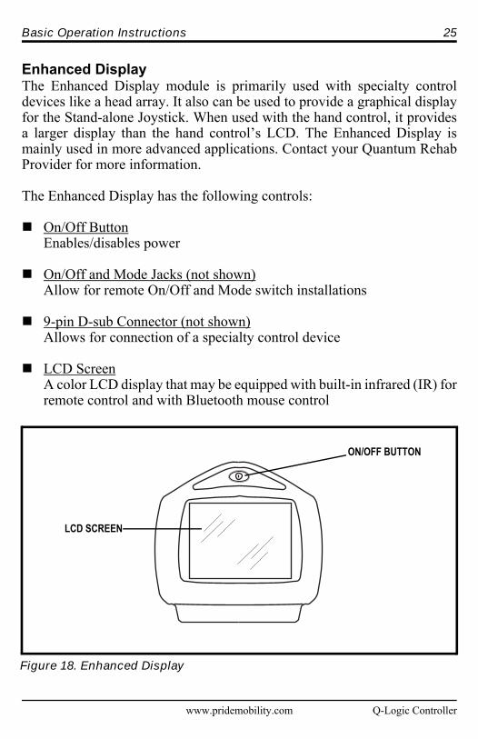
Enhanced DisplayThe Enhanced Display module is primarily used with specialty controldevices like a head array. It also can be used to provide a graphical displayfor the Stand-alone Joystick. When used with the hand control, it providesa larger display than the hand control’s LCD. The Enhanced Display ismainly used in more advanced applications. Contact your Quantum RehabProvider for more information.
The Enhanced Display has the following controls:
On/Off ButtonEnables/disables power
On/Off and Mode Jacks (not shown)Allow for remote On/Off and Mode switch installations
9-pin D-sub Connector (not shown)Allows for connection of a specialty control device
LCD ScreenA color LCD display that may be equipped with built-in infrared (IR) forremote control and with Bluetooth mouse control
Figure 18. Enhanced Display
LCD SCREEN
ON/OFF BUTTON

26 Basic Operation Instructions
Q-Logic Controller www.pridemobility.com
SLEEP MODEThe Q-Logic Controller offers a sleep mode feature that will shut off themain power if the joystick remains stationary for a programmed period oftime from 0 to 240 minutes. To restore power and resume operation of thechair, push the On/Off and Mode Select Lever up once. A set time of 0minutes disables the sleep power mode feature.
THERMAL ROLLBACKThe Q-Logic Controller is equipped with a thermal rollback circuit thatmonitors the temperature of the chair’s motors and controller. If eitherexceeds the safe operating temperature, the controller reduces the output to20% of full operation level. This reduces the chair’s speed and allows a cooldown period. Once the temperature returns to a safe level, the chair willresume normal operation.
BATTERY CONDITION METERThe battery condition meter is located in front of the joystick on the handcontrol and as an LED on the Attendant Control and Stand-alone (see figure1, 2, 3, or 17).
Hand Control Battery Condition MeterThe state of charge (SOC) on the hand control is shown two different ways:as a 180°-arc illuminated display and numerically inside the battery icon.See figure 1.
180°-arc and battery icon are green: Batteries charged.180°-arc and battery icon are yellow: Charge batteries if possible.180°-arc and battery icon are red: Charge batteries as soon as possible.
NOTE: When charging the battery, the 180°-arc will ripple continuously.
Attendant Control Battery Condition MeterThe state of charge (SOC) on the Attendant Control and Stand-alone isshown on an LED. The color of the tri-color LED indicates the battery SOC.See figure 17.
LED is green: Batteries charged.LED is amber: Charge batteries if possible.LED is red: Charge batteries as soon as possible.
NOTE: When charging the battery, the LED sequences continuously.

Basic Operation Instructions 27
www.pridemobility.com Q-Logic Controller
Q-LOGIC ERROR CODESThe Q-Logic displays four types of messages:information, warning, error, and general error.See figure 19.
Information: Displays information thatdoes not impact power chair functionality orperformance.Warning: Alerts you to conditions that mayaffect power chair functionality andperformance.Error: Alerts you to conditions thatinfluence power chair functionality andperformance.General Error: Alerts you to system orcomponent failures that greatly influencepower chair functionality and performanceand may result in emergency shutdown.
Error codes are displayed on the LCD by num-ber. The following table identifies the errorcodes that may be easily rectified, probablecauses, and possible solutions. If you receiveone of these error codes, follow the recom-mended solution, and if the problem persists, oryou receive any other error code or experienceany other problem with your power chair, con-tact your Quantum Rehab Provider.
Information
Warning
Error
General Error
#36
Figure 19. Types of Errors

28 Basic Operation Instructions
Q-Logic Controller www.pridemobility.com
CARE AND MAINTENANCERefer to your power chair owner’s manual for proper cleaning and disposalinstructions.
WARRANTYRefer to your power chair owner’s manual for specific information oncontroller warranty.
ERROR CODE DIAGNOSIS SOLUTION
35, 37 Joystick Fault/Connection Check if joystick cable is con-nected.
36, 110 Joystick Not centered Release joystick while turningchair on.
46 High Battery Voltage Disconnect charger.
47, 101, 105 Low Battery Voltage Charge battery.
49-53 Motor Not Connected Check motor brake connector.
74-75 Motor Disconnected Check motor brake connector.
81-90 Motor/Brake Fault Check motor brake connector.
107 Charger Drive Inhibit Disconnect charger.
111-112 Center Detect Fault Check joystick cable connec-tion.
131-132 Motor Fault Check motor wiring.
141, 187 Drive/Actuator Restriction Clear restriction.
192-195 Motor Disconnected/Shorted
Check motor brake connector.
200-201 Motor Fault Check motor wiring.

www.pridemobility.com Q-Logic Controller
NOTES

Q-Logic Controller www.pridemobility.com
NOTES

www.pridemobility.com Q-Logic Controller
NOTES

*INFMANU3347*
Pride Mobility Products Corporation182 Susquehanna AvenueExeter, PA 18643-2694USA
Pride Mobility Products Company380 Vansickle Road Unit 350St. Catharines, Ontario L2R 6P7Canada
Pride Mobility Products Ltd.32 Wedgwood RoadBicester, Oxon OX26 4ULUK
Pride Mobility Products Australia Pty. Ltd.21 Healey RoadDandenong, 3175Victoria, Australia
Pride Mobility Products Italia S.r.l.Via del Progresso - ang. Via del LavoroLoc. Prato della Corte00065-Fiano Romano (RM)
Pride Mobility Products Europe B.V.Castricummer Werf 261901 RW CastricumThe Netherlands