basic information - straumann · same inner geometry regardless of the diameter of the implant ѹ a...
TRANSCRIPT

Straumann® BLX Implant System
Basic Information
Technical Information
702115.indd 1 18/12/2018 09:27

702115.indd 2 18/12/2018 09:27
Table of Contents
1. The Straumann® BLX Implant System 3
2. Implant 42.1 Design and specification 4
3. Connection 53.1 TorcFit™ connection 5
4. Instruments 74.1 Drills 8
4.2 Drill extender 8
4.3 Alignment pins 9
4.4 Implant depth gauge 9
4.5 Implant driver 10
4.6 Ratchet and torque control devices 11
4.7 Surgical cassette 12
5. Surgical procedure 135.1 Preoperative planning 13
5.2 Implant bed preparation 18
5.3 Implant pick up 23
5.4 Implant placement 24
5.5 Gap management 26
5.6 Primary implant closure 28
6. Prosthetic workflow overview 306.1 Abutment overview 30
6.2 Color code 31
6.3 Prosthetic components overview 32
7. Important considerations 347.1 Implant base concept 34
7.2 How to verify correct impression post seating 35
7.3 How to verify correct final abutment seating 35
7.4 Removal of finally tightened TorcFit™ abutments 36
8. Soft tissue management 378.1 Overview of Consistent Emergence Profiles™ 38
702115.indd 1 18/12/2018 09:27

About this guide
This surgical and prosthetic procedure describes the steps required for implantation and res-toration of the Straumann® BLX Implant System. The Straumann® BLX Implant System is rec-ommended for use only by clinicians with advanced surgical skills. It is assumed that the user is familiar with placing dental implants. Not all detailed information will be found in this guide. Reference to existing Straumann® procedure manuals will be made throughout this document.
Not all products shown are available in all markets.
9. Temporary restoration 419.1 Prefabricated healing abutment made of Titan grade 4 41
9.2 Temporary abutment – titanium alloy (TAN) 42
10. Impression taking 4310.1 Conventional implant level impression taking 43
10.2 Digital impressions: Straumann® CARES® Mono Scanbody 44
11. Final restoration 4511.1 Straumann® Screw‑retained Abutments 45
11.2 Straumann® Variobase® 47
11.3 Straumann® Anatomic Abutments 50
11.4 Straumann® Novaloc® Abutments 51
11.5 Straumann® CARES® Abutments 52
11.6 Straumann® Screw‑retained Bars and Bridges (SRBB) 52
11.7 Straumann® CARES® Scan & Shape 54
11.8 Straumann® CARES® X‑Stream™ 56
12. Cleaning and care of BLX surgical instruments and the BLX surgical cassette 5712.1 Pretreatment 57
12.2 Automated cleaning and thermal disinfection using a disinfector 58
12.3 Manual cleaning and disinfection 59
12.4 Sterilization 60
702115.indd 2 18/12/2018 09:27
3
1. The Straumann® BLX Implant System
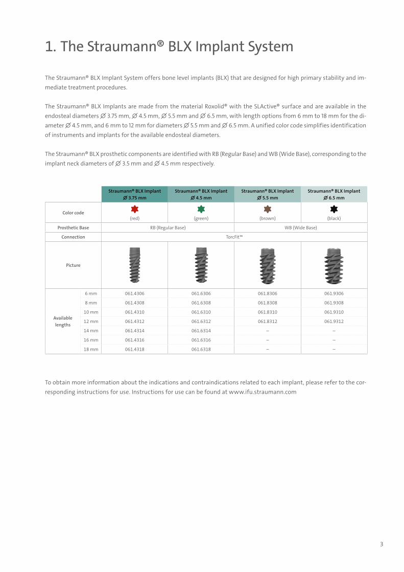
The Straumann® BLX Implant System offers bone level implants (BLX) that are designed for high primary stability and im-mediate treatment procedures.
The Straumann® BLX Implants are made from the material Roxolid® with the SLActive® surface and are available in the endosteal diameters ∅ 3.75 mm, ∅ 4.5 mm, ∅ 5.5 mm and ∅ 6.5 mm, with length options from 6 mm to 18 mm for the di-ameter ∅ 4.5 mm, and 6 mm to 12 mm for diameters ∅ 5.5 mm and ∅ 6.5 mm. A unified color code simplifies identification of instruments and implants for the available endosteal diameters.
The Straumann® BLX prosthetic components are identified with RB (Regular Base) and WB (Wide Base), corresponding to the implant neck diameters of ∅ 3.5 mm and ∅ 4.5 mm respectively.
To obtain more information about the indications and contraindications related to each implant, please refer to the cor-responding instructions for use. Instructions for use can be found at www.ifu.straumann.com
Straumann® BLX Implant∅ 3.75 mm
Straumann® BLX Implant ∅ 4.5 mm
Straumann® BLX Implant ∅ 5.5 mm
Straumann® BLX Implant ∅ 6.5 mm
Color code(red) (green) (brown) (black)
Prosthetic Base RB (Regular Base) WB (Wide Base)
Connection TorcFit™
Picture
Available lengths
6 mm 061.4306 061.6306 061.8306 061.9306
8 mm 061.4308 061.6308 061.8308 061.9308
10 mm 061.4310 061.6310 061.8310 061.9310
12 mm 061.4312 061.6312 061.8312 061.9312
14 mm 061.4314 061.6314 – –
16 mm 061.4316 061.6316 – –
18 mm 061.4318 061.6318 – –
702115.indd 3 18/12/2018 09:27

4
2. Implant
2.1 Design and specification
Straumann® BLX Implant ∅ 3.75 mm
Straumann® BLX Implant ∅ 4.5 mm
Straumann® BLX Implant ∅ 5.5 mm
Straumann® BLX Implant ∅ 6.5 mm
[A] Maximum outer diameter ∅ 3.75 mm ∅ 4.5 mm ∅ 5.5 mm ∅ 6.5 mm
[B] Neck diameter ∅ 3.5 mm ∅ 4.5 mm
[C] Platform diameter ∅ 2.9 mm
[D] Connection diameter ∅ 2.7 mm
[E] 22.5° bevel height 0.12 mm 0.33 mm
[F] Apical diameter, body ∅ 1.9 mm ∅ 2.6 mm ∅ 3.0 mm
[G] Apical diameter, threads ∅ 2.9 mm ∅ 3.6 mm ∅ 4.0 mm ∅ 5.2 mm
Number of apical cutting edges 2 4
[L] Implant lengths: 6 mm, 8 mm
[H] Neck height 1.0 mm
[M] Micro threads height 0.5 mm
[P] Thread pitch* 1.7 mm 2.0 mm 2.1 mm 2.5 mm
[T] Thread spacing 0.85 mm 1.0 mm
[L] Implant lengths: 10 mm, 12 mm, 14 mm
[H] Neck height 1.7 mm
[M] Micro threads height 0.85 mm
[P] Thread pitch* 2.2 mm 2.5 mm 2.8 mm
[T] Thread spacing 1.1 mm 1.25 mm
[L] Implant lengths: 16 mm, 18 mm
[H] Neck height 2.0 mm
NA[M] Micro threads height 1.0 mm
[P] Thread pitch* 2.6 mm 2.8 mm
[T] Thread spacing 1.3 mm 1.4 mm
M
T
E
L
H
P
D
F
G
C
B
A
Straumann® BLX Implant∅ 4.5 mm
* Implant advances by this amount with every rotation.
702115.indd 4 18/12/2018 09:27
5
3. Connection
3.1 TorcFit™ connection
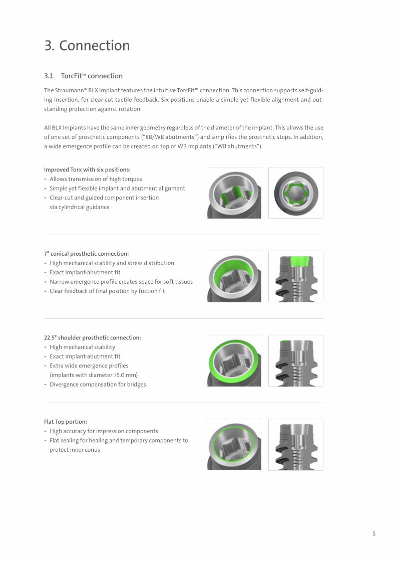
The Straumann® BLX Implant features the intuitive TorcFit™ connection. This connection supports self-guid-ing insertion, for clear-cut tactile feedback. Six positions enable a simple yet flexible alignment and out-standing protection against rotation.
All BLX Implants have the same inner geometry regardless of the diameter of the implant. This allows the use of one set of prosthetic components (“RB/WB abutments”) and simplifies the prosthetic steps. In addition, a wide emergence profile can be created on top of WB implants (“WB abutments”).
Improved Torx with six positions: ѹ Allows transmission of high torques ѹ Simple yet flexible implant and abutment alignment ѹ Clear-cut and guided component insertion
via cylindrical guidance
7° conical prosthetic connection: ѹ High mechanical stability and stress distribution ѹ Exact implant-abutment fit ѹ Narrow emergence profile creates space for soft tissues ѹ Clear feedback of final position by friction fit
22.5° shoulder prosthetic connection: ѹ High mechanical stability ѹ Exact implant-abutment fit ѹ Extra wide emergence profiles
(implants with diameter >5.0 mm) ѹ Divergence compensation for bridges
Flat Top portion: ѹ High accuracy for impression components ѹ Flat sealing for healing and temporary components to
protect inner conus
702115.indd 5 18/12/2018 09:27
6
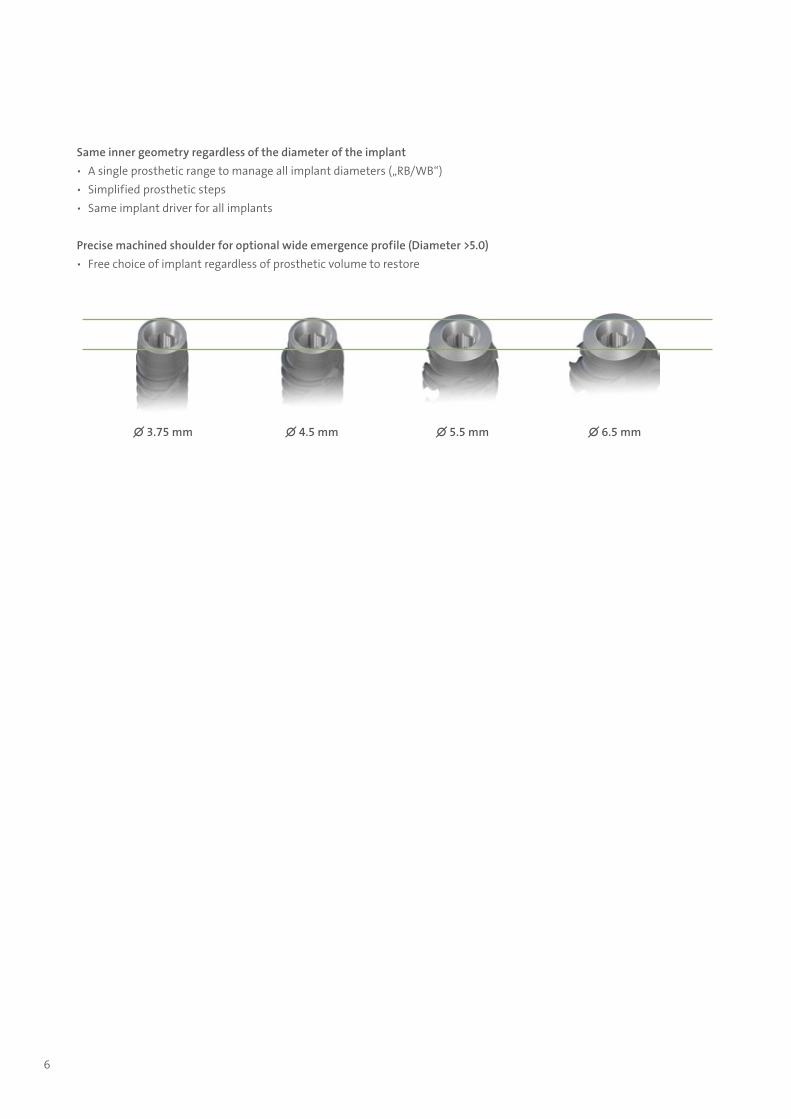
Same inner geometry regardless of the diameter of the implant ѹ A single prosthetic range to manage all implant diameters („RB/WB“) ѹ Simplified prosthetic steps ѹ Same implant driver for all implants
Precise machined shoulder for optional wide emergence profile (Diameter >5.0) ѹ Free choice of implant regardless of prosthetic volume to restore
∅ 3.75 mm ∅ 4.5 mm ∅ 5.5 mm ∅ 6.5 mm
702115.indd 6 18/12/2018 09:27
7
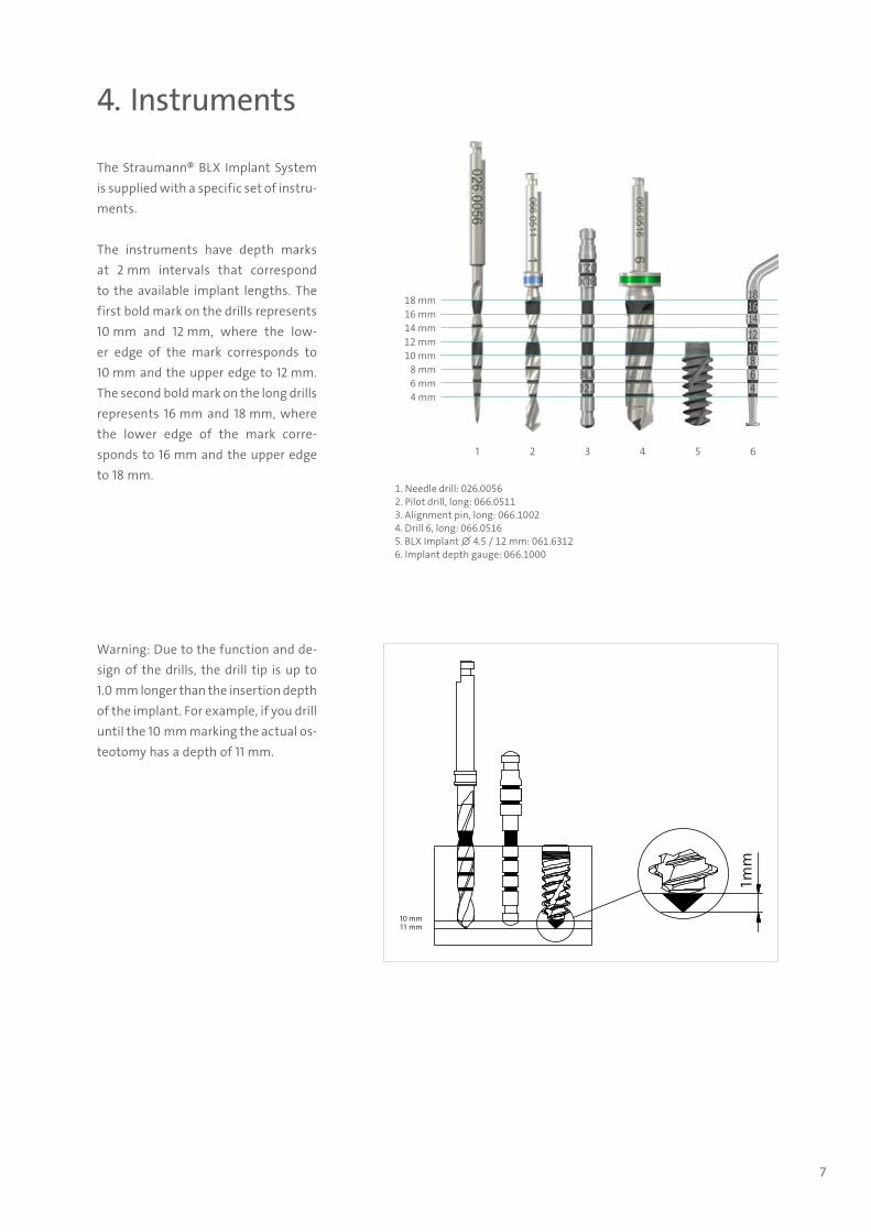
The Straumann® BLX Implant System is supplied with a specific set of instru-ments.
The instruments have depth marks at 2 mm intervals that correspond to the available implant lengths. The first bold mark on the drills represents 10 mm and 12 mm, where the low-er edge of the mark corresponds to 10 mm and the upper edge to 12 mm. The second bold mark on the long drills represents 16 mm and 18 mm, where the lower edge of the mark corre-sponds to 16 mm and the upper edge to 18 mm.
4. Instruments
12 mm14 mm16 mm18 mm
10 mm8 mm6 mm4 mm
1 2 3 4 5 6
1. Needle drill: 026.00562. Pilot drill, long: 066.05113. Alignment pin, long: 066.10024. Drill 6, long: 066.05165. BLX Implant ∅ 4.5 / 12 mm: 061.63126. Implant depth gauge: 066.1000
1mm
1 1 mm10 mm
Warning: Due to the function and de-sign of the drills, the drill tip is up to 1.0 mm longer than the insertion depth of the implant. For example, if you drill until the 10 mm marking the actual os-teotomy has a depth of 11 mm.
702115.indd 7 18/12/2018 09:27
8
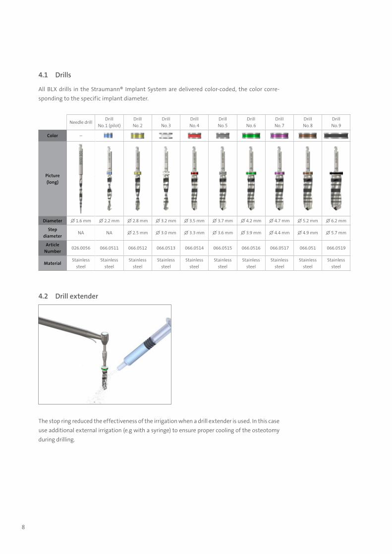
4.1 Drills
All BLX drills in the Straumann® Implant System are delivered color-coded, the color corre-sponding to the specific implant diameter.
4.2 Drill extender
Needle drillDrill
No. 1 (pilot)Drill No. 2
Drill No. 3
Drill No. 4
Drill No. 5
Drill No. 6
Drill No. 7
Drill No. 8
Drill No. 9
Color –
Picture(long)
Diameter ∅ 1.6 mm ∅ 2.2 mm ∅ 2.8 mm ∅ 3.2 mm ∅ 3.5 mm ∅ 3.7 mm ∅ 4.2 mm ∅ 4.7 mm ∅ 5.2 mm ∅ 6.2 mm
Stepdiameter
NA NA ∅ 2.5 mm ∅ 3.0 mm ∅ 3.3 mm ∅ 3.6 mm ∅ 3.9 mm ∅ 4.4 mm ∅ 4.9 mm ∅ 5.7 mm
Article Number
026.0056 066.0511 066.0512 066.0513 066.0514 066.0515 066.0516 066.0517 066.051 066.0519
MaterialStainless
steelStainless
steelStainless
steelStainless
steelStainless
steelStainless
steelStainless
steelStainless
steelStainless
steelStainless
steel
The stop ring reduced the effectiveness of the irrigation when a drill extender is used. In this case use additional external irrigation (e.g with a syringe) to ensure proper cooling of the osteotomy during drilling.
702115.indd 8 18/12/2018 09:27
9
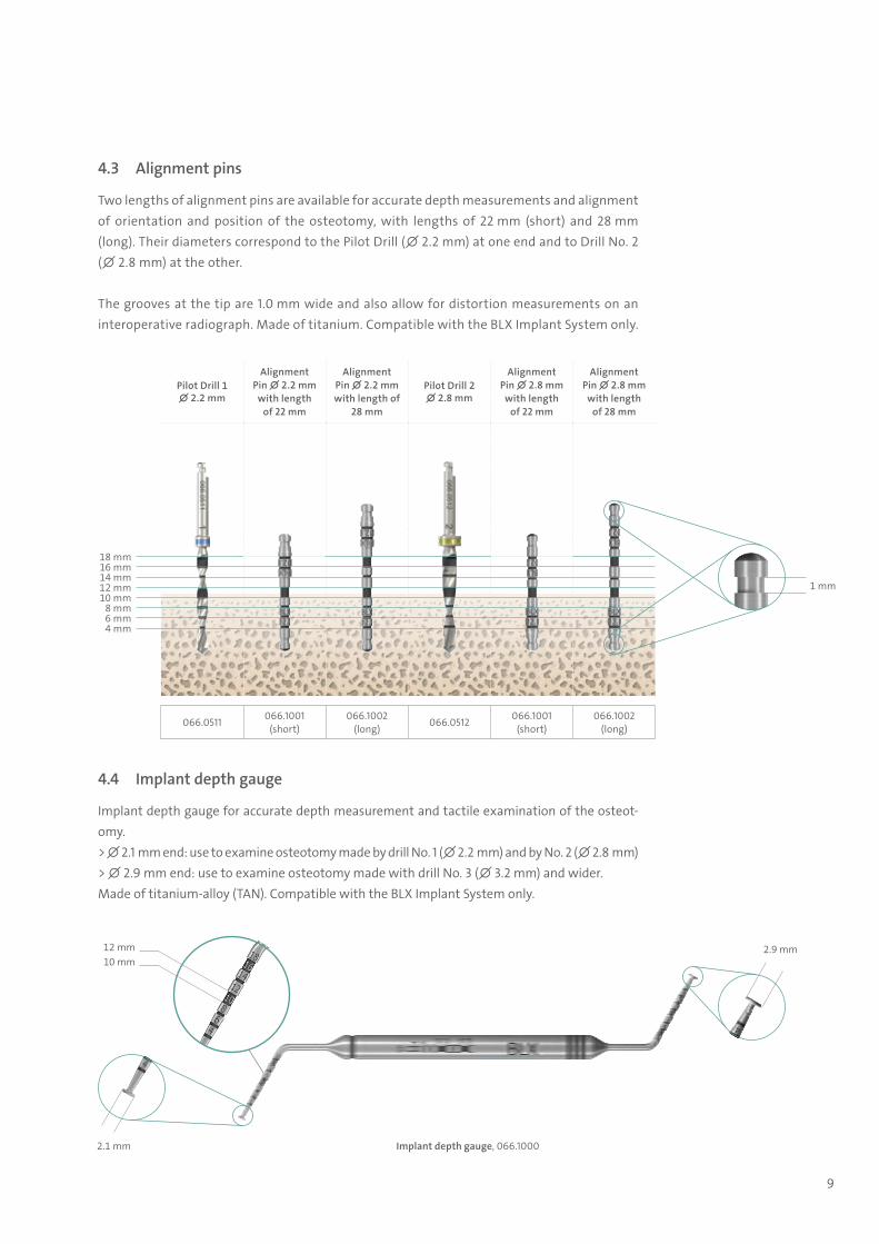
4.3 Alignment pins
Two lengths of alignment pins are available for accurate depth measurements and alignment of orientation and position of the osteotomy, with lengths of 22 mm (short) and 28 mm (long). Their diameters correspond to the Pilot Drill (∅ 2.2 mm) at one end and to Drill No. 2 (∅ 2.8 mm) at the other.
The grooves at the tip are 1.0 mm wide and also allow for distortion measurements on an interoperative radiograph. Made of titanium. Compatible with the BLX Implant System only.
4.4 Implant depth gauge
Implant depth gauge for accurate depth measurement and tactile examination of the osteot-omy.> ∅ 2.1 mm end: use to examine osteotomy made by drill No. 1 (∅ 2.2 mm) and by No. 2 (∅ 2.8 mm)> ∅ 2.9 mm end: use to examine osteotomy made with drill No. 3 (∅ 3.2 mm) and wider.Made of titanium-alloy (TAN). Compatible with the BLX Implant System only.
Pilot Drill 1∅ 2.2 mm
Alignment Pin ∅ 2.2 mm
with length of 22 mm
Alignment Pin ∅ 2.2 mm with length of
28 mm
Pilot Drill 2∅ 2.8 mm
Alignment Pin ∅ 2.8 mm
with length of 22 mm
Alignment Pin ∅ 2.8 mm
with length of 28 mm
066.0511 066.1001(short)
066.1002(long) 066.0512 066.1001
(short)066.1002
(long)
1 mm
Implant depth gauge, 066.10002.1 mm
2.9 mm10 mm12 mm
6 mm4 mm
8 mm10 mm12 mm14 mm16 mm18 mm
702115.indd 9 18/12/2018 09:27
10
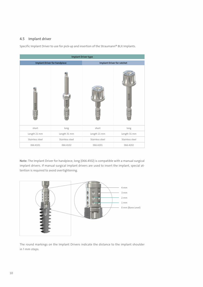
4.5 Implant driver
Specific Implant Driver to use for pick-up and insertion of the Straumann® BLX Implants.
Implant Driver type
Implant Driver for handpiece Implant Driver for ratchet
short long short long
Length 21 mm Length 31 mm Length 21 mm Length 31 mm
Stainless steel Stainless steel Stainless steel Stainless steel
066.4101 066.4102 066.4201 066.4202
Note: The Implant Driver for handpiece, long (066.4102) is compatible with a manual surgical implant drivers. If manual surgical implant drivers are used to insert the implant, special at-tention is required to avoid overtightening.
The round markings on the Implant Drivers indicate the distance to the implant shoulder in 1 mm steps.
0 mm (Bone Level)
1 mm
2 mm
3 mm
4 mm
702115.indd 10 18/12/2018 09:27
11
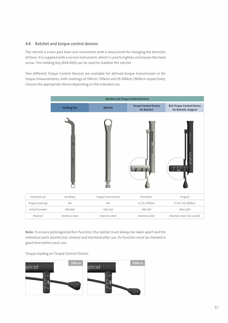
4.6 Ratchet and torque control devices
The ratchet is a two-part lever arm instrument with a rotary knob for changing the direction of force. It is supplied with a service instrument, which is used to tighten and loosen the head screw. The Holding Key (046.064) can be used to stabilize the ratchet.
Two different Torque Control Devices are available for defined torque transmission or for torque measurements, with markings of 15Ncm / 35Ncm and 35-50Ncm / 80Ncm respectively. Choose the appropriate device depending on the intended use.
Note: To ensure prolonged perfect function, the ratchet must always be taken apart and the individual parts disinfected, cleaned and sterilized after use. Its function must be checked in good time before each use.
Ratchet and Torque Control Devices
Holding Key RatchetTorque Control Device
for RatchetBLX Torque Control Device
for Ratchet, Surgical
Intended use Auxilliary Torque transmission Prosthetic Surgical
Torque markings NA NA 0 / 15 / 35Ncm 0 / 35 / 50 / 80Ncm
Article Number 046.064 046.119 046.049 066.1100
Material Stainless steel Stainless steel Stainless steel Stainless steel, DLC coated
Torque reading on Torque Control Device:
50Ncm35Ncm
702115.indd 11 18/12/2018 09:27

12
4.7 Surgical cassette
The Straumann® BLX Surgical Cassette (069.0001) is used for the secure storage, cleaning and sterilization of the surgical instruments and auxiliary instruments. For guidelines on how to clean and sterilize the cassette with or without inserted instru-ments, please see Chapter 12.
Dimensions of closed box: 143 X 100 X 61 mm
Lower tray
040.563
066.4202
066.4201
Long Drills see Chapter 4.1
066.4102
066.4101
046.119 Ratchet body
046.119 Bolt
046.411
046.401
Closed box
143 mm
100 mm
61 mm
Upper tray
066.1000
066.1100
066.1002
066.1001
702115.indd 12 18/12/2018 09:27
13
5. Surgical procedure
The workflow for the surgical procedure for the Straumann® BLX Implant System involves 3 steps: ѹ Preoperative planning ѹ Implant bed preparation ѹ Implant insertion
5.1 Preoperative planning
Prosthetic-driven planning is recommended, and close communication between the patient, dentist, surgeon and dental technician is imperative for achieving the desired esthetic result.
To determine the topographical situation, axial orientation and the appropriate implants, making a wax-up / set up using the previously prepared study cast is recommended. Subsequently, the type of superstructure can be defined. The wax-up / set-up can later be used as the basis for a custom-made x-ray or drill template and for a temporary restoration.
Note: Abutments should always be loaded axially. Ideally, the long axis of the implant is aligned with the cusps of the opposing tooth. Extreme cusp formation should be avoided as this can lead to unphysiological loading.
The mesiodistal bone availability is an important factor when choosing the implant type and diameter as well as the inter-implant distances if multiple implants are placed. The point of reference on the implant for measuring mesiodistal distances is always the largest diameter of the implant.
702115.indd 13 18/12/2018 09:27
14
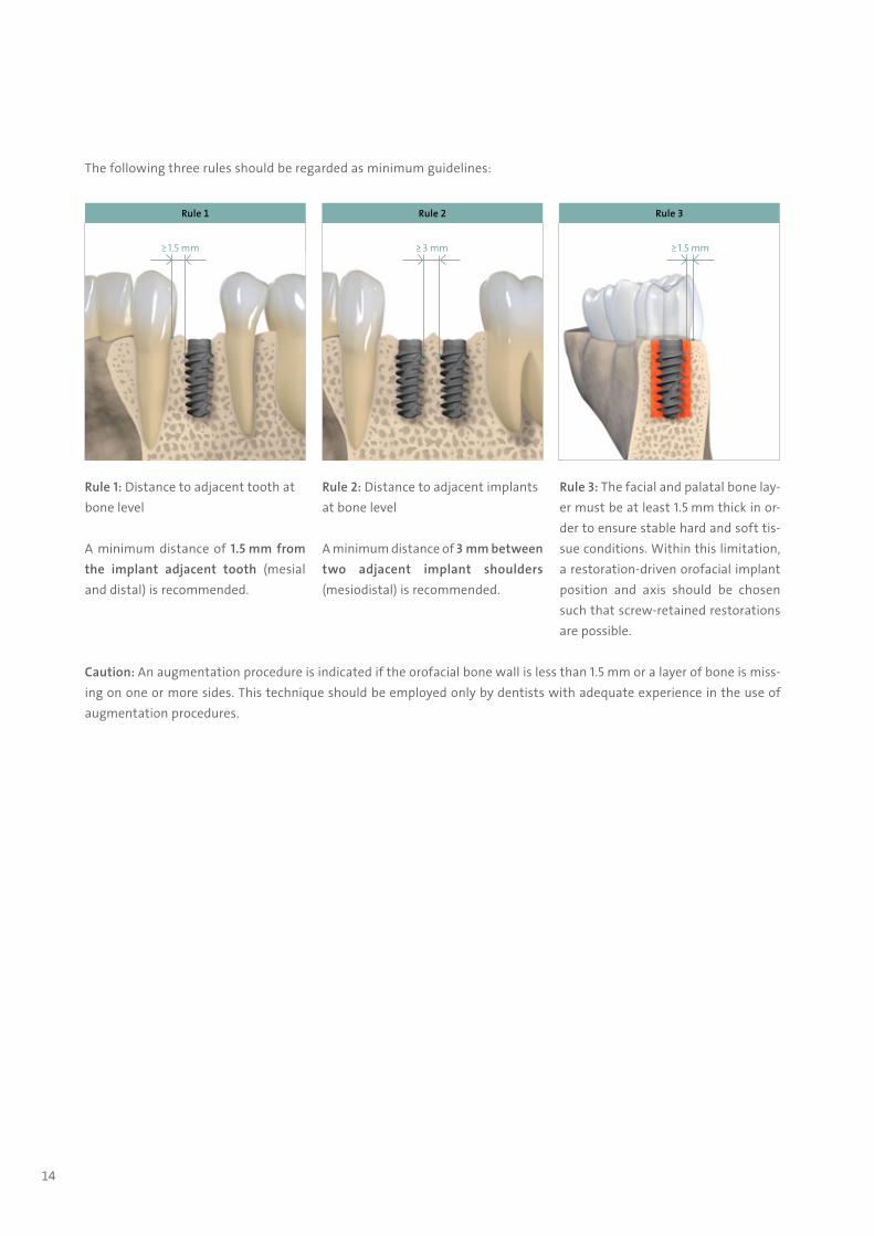
Rule 1: Distance to adjacent tooth at bone level
A minimum distance of 1.5 mm from the implant adjacent tooth (mesial and distal) is recommended.
Rule 2: Distance to adjacent implants at bone level
A minimum distance of 3 mm between two adjacent implant shoulders (mesio distal) is recommended.
Rule 3: The facial and palatal bone lay-er must be at least 1.5 mm thick in or-der to ensure stable hard and soft tis-sue conditions. Within this limitation, a restoration-driven orofacial implant position and axis should be chosen such that screw-retained restorations are possible.
Caution: An augmentation procedure is indicated if the orofacial bone wall is less than 1.5 mm or a layer of bone is miss-ing on one or more sides. This technique should be employed only by dentists with adequate experience in the use of augmentation procedures.
Rule 3
≥ 1.5 mm
Rule 2
≥ 3 mm
Rule 1
≥ 1.5 mm
The following three rules should be regarded as minimum guidelines:
702115.indd 14 18/12/2018 09:27
15
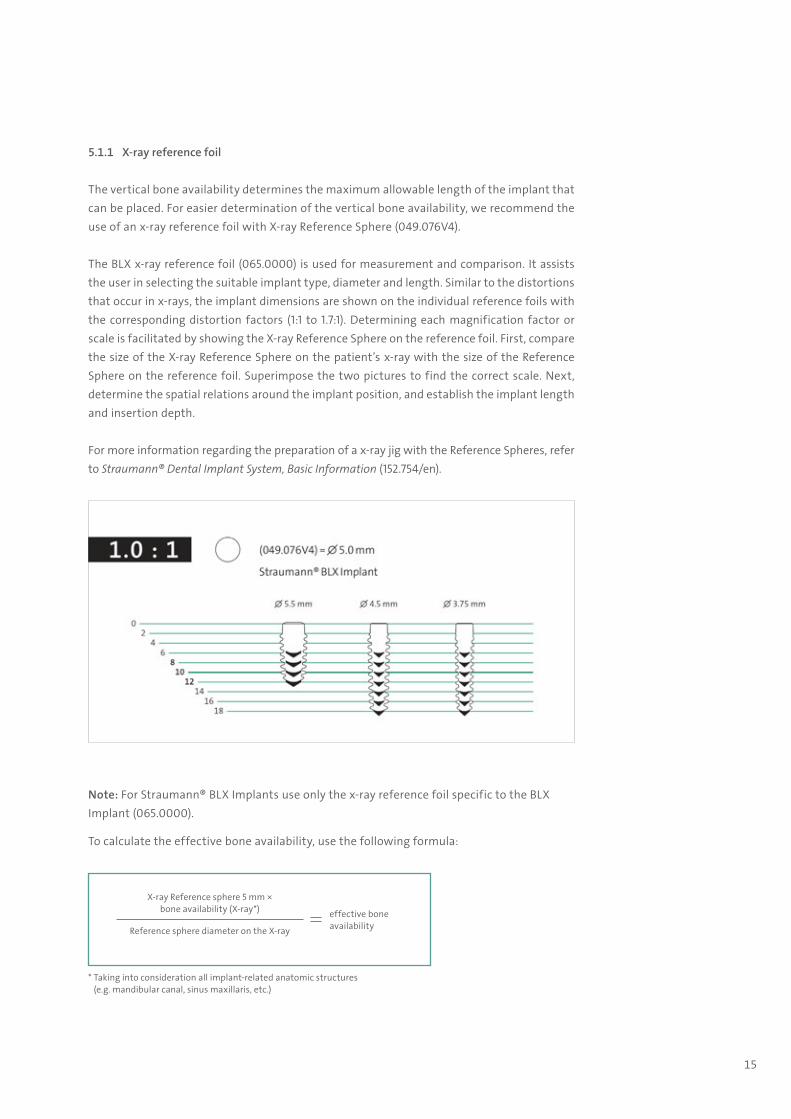
5.1.1 X-ray reference foil
The vertical bone availability determines the maximum allowable length of the implant that can be placed. For easier determination of the vertical bone availability, we recommend the use of an x-ray reference foil with X-ray Reference Sphere (049.076V4).
The BLX x-ray reference foil (065.0000) is used for measurement and comparison. It assists the user in selecting the suitable implant type, diameter and length. Similar to the distortions that occur in x-rays, the implant dimensions are shown on the individual reference foils with the corresponding distortion factors (1:1 to 1.7:1). Determining each magnification factor or scale is facilitated by showing the X-ray Reference Sphere on the reference foil. First, compare the size of the X-ray Reference Sphere on the patient’s x-ray with the size of the Reference Sphere on the reference foil. Superimpose the two pictures to find the correct scale. Next, determine the spatial relations around the implant position, and establish the implant length and insertion depth.
For more information regarding the preparation of a x-ray jig with the Reference Spheres, refer to Straumann® Dental Implant System, Basic Information (152.754/en).
* Taking into consideration all implant-related anatomic structures (e.g. mandibular canal, sinus maxillaris, etc.)
effective bone availabilityReference sphere diameter on the X-ray
Note: For Straumann® BLX Implants use only the x-ray reference foil specific to the BLX Implant (065.0000).
To calculate the effective bone availability, use the following formula:
X-ray Reference sphere 5 mm × bone availability (X-ray*)
702115.indd 15 18/12/2018 09:27

16
5.1.2 Planning software
Another possibility is digital planning with e.g. coDiagnostiX®. This 3D diagnostics and implant planning software is designed for the image-guided surgical planning of dental implants, including BLX Implants, which are included in the system’s digital library. Working with the software is based on a patient’s medical image data, such as a CT (Computed Tomography) or DVT (Digital Volume Tomography) scan processed by coDiagnostiX®.
Planning includes the calculation of several views (such as virtual OPG or a 3-dimensional re-construction of the image dataset), analysis of the image data and the placement of implants, abutments and drilling sleeves.
coDiagnostiX® software is designed for use by professionals with appropriate knowledge in implantology and surgical dentistry. For further information, please refer to the coDiagnostiX® Manual.
CARES® Synergy workflowCARES® Synergy provides real-time communication between the implant planning software (coDiagnostiX®) and the lab software (i.e. Straumann® CARES® Visual) and improves implant planning by visualizing the relation-ship between the proposed implant position and the proposed restoration.
702115.indd 16 18/12/2018 09:27

17
5.1.3 Straumann® Pro Arch Guide
For intraoperative visual and three-dimensional orientation of the implant angulation (mesial/distal) and oral parallelization, use the Straumann® Pro Arch Guide.
The Pro Arch Guide is used in edentulous jaws for surgical implant placement. The Pro Arch Guide can be easily bent to adapt to the dental arch. It is secured by drilling into the symphysis with a ∅ 2.2 mm Pilot Drill and a pin in the jaw. The drilling depth for the bone cavity of the pin is 10 mm. The drilling depth can be checked optically using the depth markings on the drills. For adjustment and disassembly use the TS Hexagonal Screwdriver (046.420).
5.1.4 Bone density definition
For further information about treatment of edentulous patients and angulated placement of BLX Implants, please refer to the Straumann® Pro Arch, Basic Information (490.015/en).
Straumann® Pro Arch Guide (026.0016)
Cross sectional view of different types of bone quality*
Type I Type II / III Type IV
Hard Medium Soft
Thick cortical bone with marrow cavity Thin cortical bone with dense trabec-ular bone of good strength
Very thin cortical bone with low den-sity trabecular bone of poor strength
* Lekholm U, Zarb G. Patient selection and preparation in Tissue Integrated Prostheses. Branemark P I, Zarb G A, Albrektsson T (eds). pp199–210. Quintessence, 1985..
702115.indd 17 18/12/2018 09:27

18
5.2 Implant bed preparation
The Straumann® BLX Surgical Cassette with specific instruments is used to prepare the im-plant bed. Different drill protocols should be employed depending on the bone density. This offers the flexibility to adapt the implant bed preparation to the individual bone quality and anatomical situation.
A quick guide to the surgical drill protocol is printed on the BLX surgical cassette and indicates the final drill recommended for each implant diameter and bone density.
Numbers in brackets (): to a depth of 4 mm (for implant lengths 6 mm and 8 mm) and 6 mm (for implant lengths 10 mm and longer) only in order to widen the coronal part of the implant bed.
Note: Every implant bed has to be initiated with the pilot drill (∅ 2.2 mm). On the quick guide only the final drill is displayed. The clinician can decide whether or not a sequence of drills with increasing diameters is used. Use the drills in a clockwise drill rotation direction, use intermittent drilling technique and provide ample cooling with pre-cooled (5°C, 41°F) sterile saline solution. Do not exceed the recommend drill speeds.
Soft Medium Hard
∅ 3.75 mm 2 3 (5) 4 (5)
∅ 4.5 mm 2 5 6
∅ 5.5 mm 3 7 8
∅ 6.5 mm 4 8 (9) 9
702115.indd 18 18/12/2018 09:27

19
5.2.1 Workflow for BLX ∅ 3.75 mm
Implant bed preparation, illustrated with a BLX Implant ∅ 3.75 mm / 12 mm RB
Mark the implantation site
Pilot drilling Check implant axis
Decide on bone density
Finalize Implant BedAccording to bone density
Implant placement
Needle Drill∅ 1.6 mm
Pilot Drill 1∅ 2.2 mm
Alignment Pin 2.2 mm
Drill 2∅ 2.8 mm
Alignment Pin 2.8 mm
Drill 3∅ 3.2 mm
Drill 4∅ 3.5 mm
Drill 5∅ 3.7 mm
BLX ∅ 3.75 SLActive® 12,
RXD
Soft
Medium c
Hard c
800 rpm 800 rpm 800 rpm 800 rpm 800 rpm 800 rpm 15 rpm
026.0056 066.0511 066.0512 066.0513 066.0514 066.0515
Recommended – full depth
Recommended – cortical only- do a depth of 4 mm for implants with a length of 6 mm and 8 mm- do a depth of 6 mm for implants with a length of 10 mm to 18 mm
c
Warning: Due to the function and design of the drills, the drill tip is up to 1.0 mm longer than the insertion depth of the implant. For example, if you drill until the 10 mm marking, the actual implant bed has a depth of 11 mm.
702115.indd 19 18/12/2018 09:27

20
5.2.2 Workflow for BLX ∅ 4.5 mm
Implant bed preparation, illustrated with a BLX Implant ∅ 4.5 mm / 12 mm RB
Recommended – full depth
Mark the implantation site
Pilot drilling Check implant axis
Decide on bone density
Finalize Implant BedAccording to bone density
Implant placement
Needle Drill∅ 1.6 mm
Pilot Drill 1∅ 2.2 mm
Alignment Pin 2.2 mm
Drill 2∅ 2.8 mm
Alignment Pin 2.8 mm
Drill 3∅ 3.2 mm
Drill 5∅ 3.7 mm
Drill 6∅ 4.2 mm
BLX ∅ 4.5 SLActive® 12,
RXD
Soft
Medium
Hard
800 rpm 800 rpm 800 rpm 800 rpm 800 rpm 800 rpm 15 rpm
026.0056 066.0511 066.0512 066.0513 066.0515 066.0516
702115.indd 20 18/12/2018 09:27
21
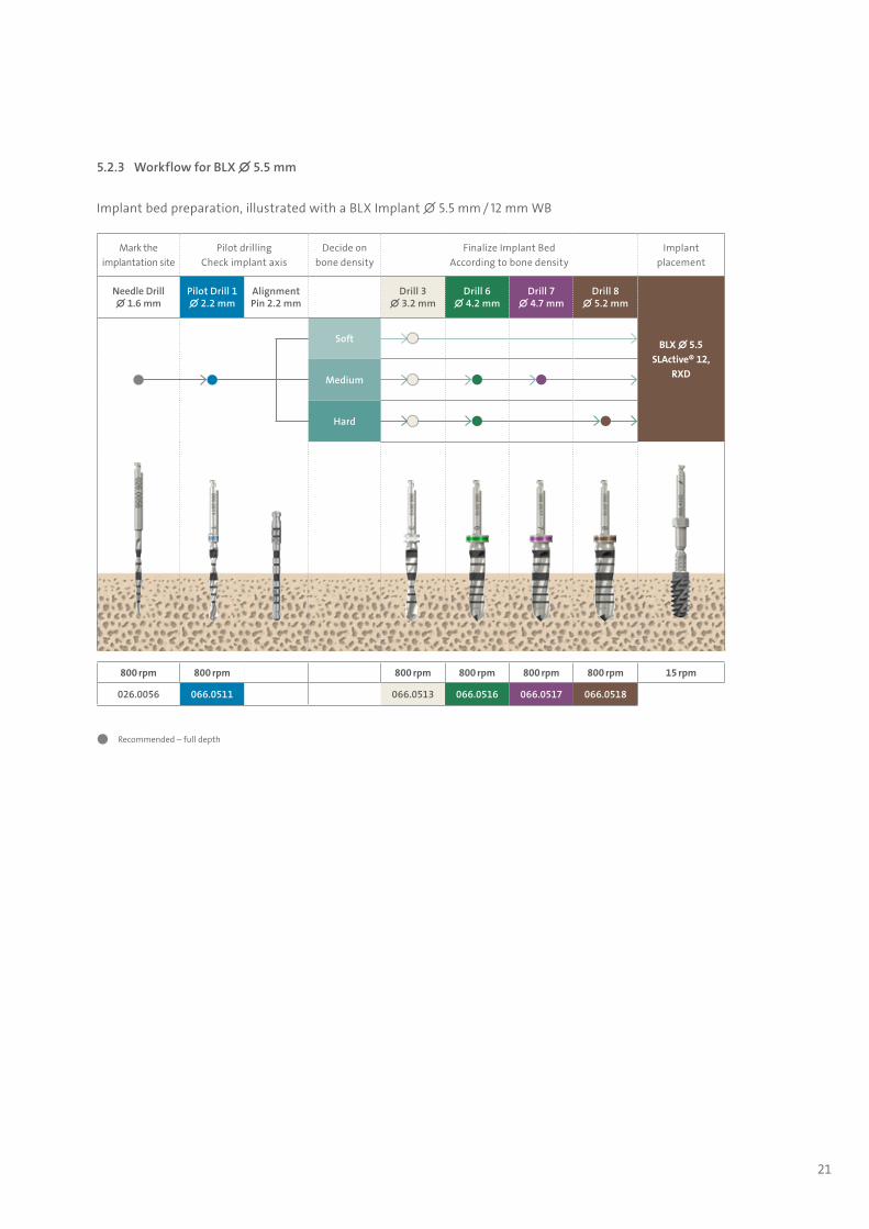
5.2.3 Workflow for BLX ∅ 5.5 mm
Implant bed preparation, illustrated with a BLX Implant ∅ 5.5 mm / 12 mm WB
Mark the implantation site
Pilot drilling Check implant axis
Decide on bone density
Finalize Implant BedAccording to bone density
Implant placement
Needle Drill∅ 1.6 mm
Pilot Drill 1∅ 2.2 mm
Alignment Pin 2.2 mm
Drill 3∅ 3.2 mm
Drill 6∅ 4.2 mm
Drill 7∅ 4.7 mm
Drill 8∅ 5.2 mm
BLX ∅ 5.5 SLActive® 12,
RXD
Soft
Medium
Hard
800 rpm 800 rpm 800 rpm 800 rpm 800 rpm 800 rpm 15 rpm
026.0056 066.0511 066.0513 066.0516 066.0517 066.0518
Recommended – full depth
702115.indd 21 18/12/2018 09:27
22
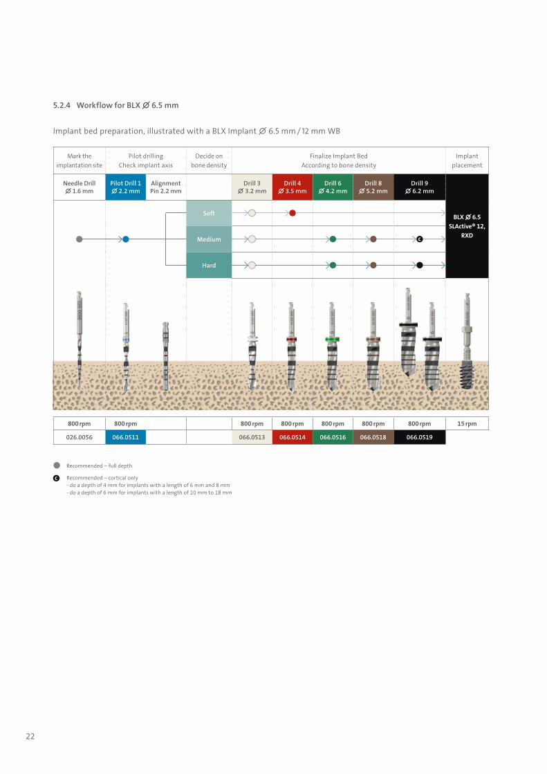
5.2.4 Workflow for BLX ∅ 6.5 mm
Implant bed preparation, illustrated with a BLX Implant ∅ 6.5 mm / 12 mm WB
Mark the implantation site
Pilot drilling Check implant axis
Decide on bone density
Finalize Implant BedAccording to bone density
Implant placement
Needle Drill∅ 1.6 mm
Pilot Drill 1∅ 2.2 mm
Alignment Pin 2.2 mm
Drill 3∅ 3.2 mm
Drill 4∅ 3.5 mm
Drill 6∅ 4.2 mm
Drill 8∅ 5.2 mm
Drill 9∅ 6.2 mm
BLX ∅ 6.5 SLActive® 12,
RXD
Soft
Medium c
Hard
800 rpm 800 rpm 800 rpm 800 rpm 800 rpm 800 rpm 800 rpm 15 rpm
026.0056 066.0511 066.0513 066.0514 066.0516 066.0518 066.0519
Recommended – full depth
Recommended – cortical only- do a depth of 4 mm for implants with a length of 6 mm and 8 mm- do a depth of 6 mm for implants with a length of 10 mm to 18 mm
c
702115.indd 22 18/12/2018 09:27

23
5.3 Implant pick up
The BLX Implants are provided with a new implant carrying system that supports direct pick-up with an appropriate Implant Driver.
1 Step 1 – Open box and remove seal of blister to get access to the implant vial.
Note: Patient label can be found on the blister seal. The blister en-sures the sterility of the implant. Do not open the blister until im-mediately prior to implant placement.
2 Step 2 – Open the vial with a counter-clockwise turn and remove the lid together with the implant.
3 Step 3 – Hold the vial lid and connect the Implant Driver to the implant using the handpiece. You hear a click when the Driver is attached correctly.
Caution: Make sure that the implant driver is properly seated and pull slightly on the driver to verify that it is correctly attached. This check must be performed before every use even when the driver has been successfully used before. Replace the driver with a new one if insufficient attachment occurs.
4 Step 4 – A slight clockwise turn is needed to remove the implant from its holder.
Note: after removing the implant from the solution, the chemical activity of SLActive® is ensured for 15 minutes.
702115.indd 23 18/12/2018 09:27
24
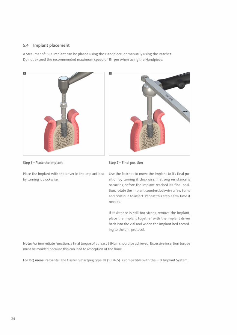
5.4 Implant placement
A Straumann® BLX Implant can be placed using the Handpiece, or manually using the Ratchet.Do not exceed the recommended maximum speed of 15 rpm when using the Handpiece.
1 2
Note: For immediate function, a final torque of at least 35Ncm should be achieved. Excessive insertion torque must be avoided because this can lead to resorption of the bone.
For ISQ measurements: The Osstell Smartpeg type 38 (100455) is compatible with the BLX Implant System.
Step 1 – Place the implant
Place the implant with the driver in the Implant bed by turning it clockwise.
Step 2 – Final position
Use the Ratchet to move the implant to its final po-sition by turning it clockwise. If strong resistance is occurring before the implant reached its final posi-tion, rotate the implant counterclockwise a few turns and continue to insert. Repeat this step a few time if needed.
If resistance is still too strong remove the implant, place the implant together with the implant driver back into the vial and widen the implant bed accord-ing to the drill protocol.
702115.indd 24 18/12/2018 09:27
25
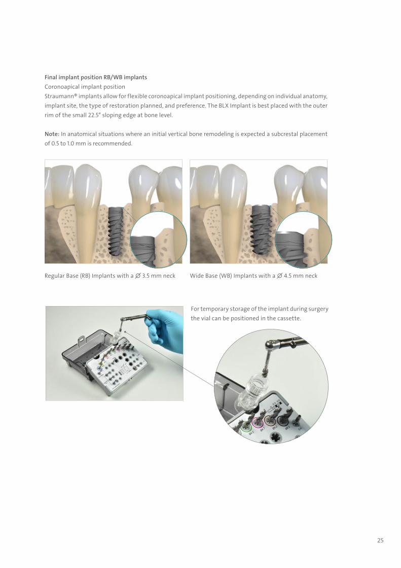
Final implant position RB/WB implantsCoronoapical implant positionStraumann® implants allow for flexible coronoapical implant positioning, depending on individual anatomy, implant site, the type of restoration planned, and preference. The BLX Implant is best placed with the outer rim of the small 22.5° sloping edge at bone level.
Regular Base (RB) Implants with a ∅ 3.5 mm neck Wide Base (WB) Implants with a ∅ 4.5 mm neck
For temporary storage of the implant during surgery the vial can be positioned in the cassette.
Note: In anatomical situations where an initial vertical bone remodeling is expected a subcrestal placement of 0.5 to 1.0 mm is recommended.
702115.indd 25 18/12/2018 09:27

26
5.5 Gap management
As no implant will match the individual anatomical situation after tooth extraction, immediate treatment procedures may require additional bone grafting (“gap management”) and soft tissue/wound healing management.
Different grafting materials, barrier membranes and healing agents are being used to support safe, enduring stability of the implant inside the bony compartment as well as sufficient hard and soft tissue to ensure esthetics.
Bone grafting materials Product Country availability Reason why
Allograft botiss maxgraft® Selected countries in Europe
Fast graft to bone turnover supporting early and long-term implant stabilityFull remodeling potential
Bone vitality
Xenograft botiss cerabone® Global (not US, CD) Long-term graft presence supporting volume preservation
Synthetic alternativeStraumann®
BoneCeramic™Global
Prolonged graft to bone turnoverVolume preservation
702115.indd 26 18/12/2018 09:27

27
The immediacy approach for placing dental implants is demanding on the human body. With its clinically proven beneficial impact on wound healing and treasured influence on scar tissue, Straumann® Emdogain can make a real difference. A thin layer of Emdogain on top of the membrane and after socket closure is our recommendation.
Barrier membranes prohibit the penetration of cells, primarily epithelial, through its structure and thus allow the slow grow-ing bone tissue to re-occupy the grafted space.
Barrier Membranes Product Country availability Reason why
Porcine collagen membrane
botiss jason® Global
Very thin but strong structureEasy handling
Prolonged barrier functionFully resorbable
Straumann® Membrane FlexNorth America, Iberia,
Distributor & Emerging Markets (Europe, Middle East and Africa)
Appropriate barrier function for non-complex cases
Easy handlingFully resorbablebotiss collprotect® Europe
Bovine collagen membrane Straumann® Membrane Plus North AmericaLong barrier function
Fully resobable
Synthetic dPTFE membrane botiss permamem® Europe
Ultra thin, strong structureOpen healing possible
Non-resorbable Has to be removed manually after <4 weeks
702115.indd 27 18/12/2018 09:27
28
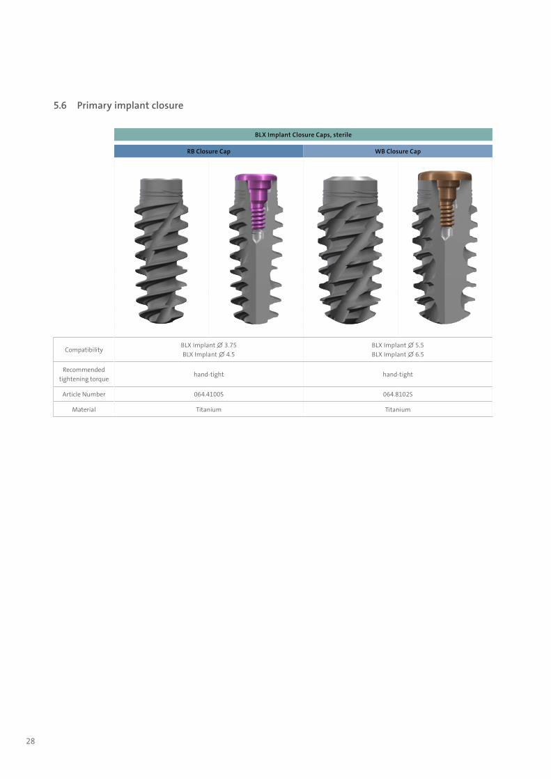
5.6 Primary implant closure
BLX Implant Closure Caps, sterile
RB Closure Cap WB Closure Cap
CompatibilityBLX Implant ∅ 3.75 BLX Implant ∅ 4.5
BLX Implant ∅ 5.5BLX Implant ∅ 6.5
Recommended tightening torque
hand-tight hand-tight
Article Number 064.4100S 064.8102S
Material Titanium Titanium
702115.indd 28 18/12/2018 09:27

29
702115.indd 29 18/12/2018 09:27

30
6. Prosthetic workflow overview
6.1 Abutment overview
Single and multi-unit replacement Edentulous treatment
Screw-retained Cement-retained Fixed Removable
CARES® Screw-retained Bridge
Screw- retained
Abutment*
Anatomic Abutment
CARES® Abutment
TAN
CARES® Advanced Fixed Bar
Screw- retained
Abutment*
CARES® Milled Bar Screw-
retained Abutment*
CARES® Basic Fixed Bar
CARES® Screw-retained Bridge
Variobase® Abutment
Variobase® Abutment
Anat
omic
Ab
utm
ent
Stra
uman
n®
Vario
base
® fo
r Cro
wn
Vario
base
® fo
r Brid
ge/B
ar
Cylin
dric
al
Vario
base
® fo
r Cro
wn
AS
Stra
uman
n®
Scre
w-r
etai
ned
Abut
men
t
Stra
uman
n®
CARE
S®
Abut
men
t TAN
Stra
uman
n®
CARE
S®
Brid
ge/B
ar
Stra
uman
n®
Nov
aloc
® AD
LC
k 062.49
Single crown
Screw-retained • • •
Cement-retained • • • •
Bridge
Screw-retained • • •
Cement-retained • • •
Removable overdentures
Telescope •
Retentive anchor •
Bar • •
Impression
Implant level • • • • •
Abutment level •
Material*Titanium
alloyTitanium
alloyTitanium
alloyTitanium
alloyTitanium
alloyTitanium
alloyTitanium
alloyTitanium
alloy
702115.indd 30 18/12/2018 09:27
31
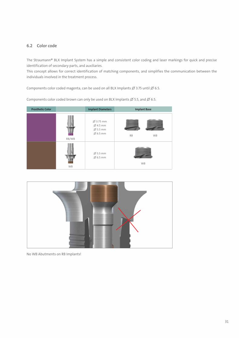
6.2 Color code
The Straumann® BLX Implant System has a simple and consistent color coding and laser markings for quick and precise identification of secondary parts, and auxiliaries. This concept allows for correct identification of matching components, and simplifies the communication between the individuals involved in the treatment process.
Components color coded magenta, can be used on all BLX Implants ∅ 3.75 until ∅ 6.5.
Components color coded brown can only be used on BLX Implants ∅ 5.5, and ∅ 6.5.
Prosthetic Color Implant Diameters Implant Base
RB/WB
∅ 3.75 mm∅ 4.5 mm∅ 5.5 mm∅ 6.5 mm
RB WB
WB
∅ 5.5 mm∅ 6.5 mm
WB
No WB Abutments on RB Implants!
702115.indd 31 18/12/2018 09:27
32
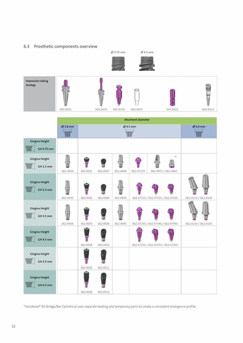
Abutment diameter
∅ 3.8 mm ∅ 4.5 mm ∅ 6.0 mm
Gingiva Height
GH 0.75 mm
Gingiva Height
GH 1.5 mm
*
062.4934 062.4501 062.4507 062.4944 062.4722S 062.4972 / 062.4961
Gingiva Height
GH 2.5 mm
062.4935 062.4502 062.4508 062.4945 062.4723S / 062.4733S / 062.4743S 062.4153 / 062.4104
Gingiva Height
GH 3.5 mm
062.4936 062.4503 062.4509 062.4945 062.4724S / 062.4734S / 062.4744S 062.4154 / 062.4103
Gingiva Height
GH 4.5 mm 062.4504 062.4510 062.4725S / 062.4735S / 062.4745S
Gingiva Height
GH 5.5 mm
062.4505 062.4511
Gingiva Height
GH 6.5 mm
062.4506 062.4512
*Variobase® for Bridge/Bar Cylindrical uses separate healing and temporary parts to create a consistent emergence profile.
6.3 Prosthetic components overview∅ 3.75 mm ∅ 4.5 mm
Impression taking Analogs
065.0031 065.0033 065.4310 065.0035 065.0021 065.0023
702115.indd 32 18/12/2018 09:27
33
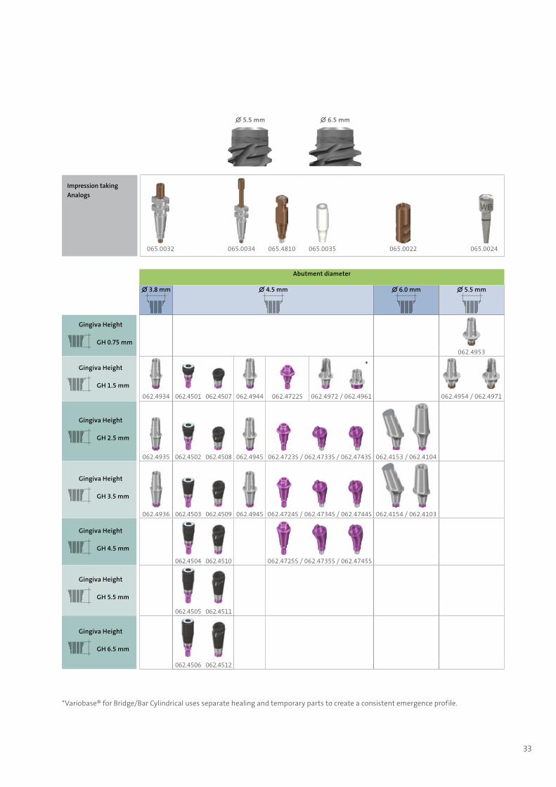
∅ 5.5 mm ∅ 6.5 mm
Impression taking Analogs
065.0032 065.0034 065.4810 065.0035 065.0022 065.0024
Abutment diameter
∅ 3.8 mm ∅ 4.5 mm ∅ 6.0 mm ∅ 5.5 mm
Gingiva Height
GH 0.75 mm062.4953
Gingiva Height
GH 1.5 mm
*
062.4934 062.4501 062.4507 062.4944 062.4722S 062.4972 / 062.4961 062.4954 / 062.4971
Gingiva Height
GH 2.5 mm
062.4935 062.4502 062.4508 062.4945 062.4723S / 062.4733S / 062.4743S 062.4153 / 062.4104
Gingiva Height
GH 3.5 mm
062.4936 062.4503 062.4509 062.4945 062.4724S / 062.4734S / 062.4744S 062.4154 / 062.4103
Gingiva Height
GH 4.5 mm 062.4504 062.4510 062.4725S / 062.4735S / 062.4745S
Gingiva Height
GH 5.5 mm
062.4505 062.4511
Gingiva Height
GH 6.5 mm
062.4506 062.4512
*Variobase® for Bridge/Bar Cylindrical uses separate healing and temporary parts to create a consistent emergence profile.
702115.indd 33 18/12/2018 09:27

34
7. Important considerations
7.1 Implant base concept
One prosthetic range ѹ RB/WB abutments fit on all BLX Implants
Optional: ѹ WB abutments fit only on implants with an implant diameter larger than 5.0. WB abutments create a wide emergence
profile starting from the shoulder
∅ 3.75 mm ∅ 4.5 mm ∅ 5.5 mm ∅ 6.5 mm
702115.indd 34 18/12/2018 09:27
35
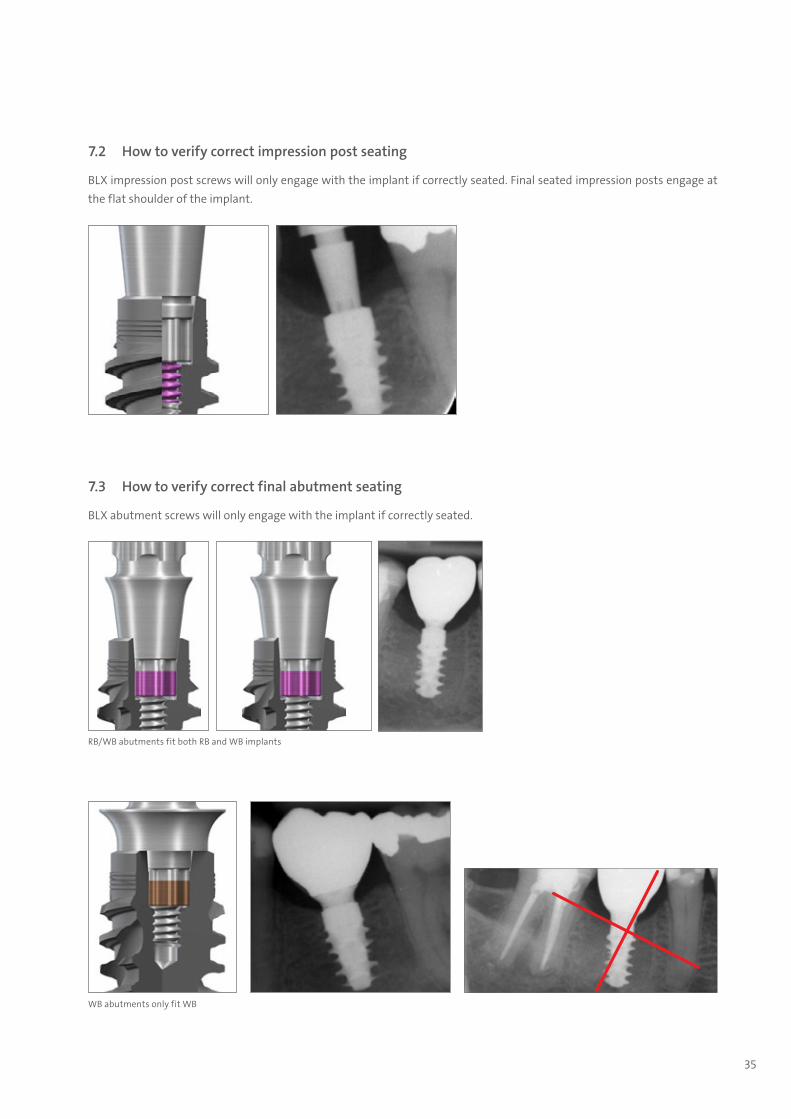
7.2 How to verify correct impression post seating
BLX impression post screws will only engage with the implant if correctly seated. Final seated impression posts engage at the flat shoulder of the implant.
7.3 How to verify correct final abutment seating
BLX abutment screws will only engage with the implant if correctly seated.
RB/WB abutments fit both RB and WB implants
WB abutments only fit WB
702115.indd 35 18/12/2018 09:27

36
7.4 Removal of finally tightened TorcFit™ abutments
Due to tight sealing of the 7° conus of the TorcFit™ connection, abutments can lock strongly in the implant after final insertion.
The RB/WB Abutment Removal Screw pushes the abutment out of the im-plant without applying high torque or bending moments to the bone.
7.4.1 Removal Tool for BLX Basal Screw (065.0008 and 065.0009)
If the basal screw can not be lifted with the SCS screwdriver after untightening [1] the Removal Tool may be used.
This tool features a left-hand thread that engages in the basal screw head [2] in order to lift the Basal Screw [3].
7.4.2 RB/WB Abutment Removal Screw (065.007)
In case the Abutment can not be re-moved by hand due to the friction fit the Abutment removal screw can be used to push out the Abutment.
Connect the SCS Screwdriver to the re-moval screw and screw it into the abut-ment [4] until the abutment is pushed out and can be removed [5].
Please note: For Variobase® for Crown AS, it might be necessary to cut the crown to access the screw channel with the RB/WB Abutment Removal Screw.
4
1 2 3
5
Left Left
702115.indd 36 18/12/2018 09:27

37
The Straumann® BLX Implant line puts a strong emphasis on esthetic considerations. It offers tailor-made solutions that allow for natural soft tissue shaping and maintenance in all indications. A versatile portfolio of healing and temporary abutments is available, for easy and fast processing.
Esthetic results are determined by successful soft tissue management. To optimize the soft tissue management process, all healing abutments, temporary abutments and final abutments feature Consistent Emergence Profiles™. Thus, the emer-gence profiles are uniform throughout the treatment process.
8. Soft tissue management
Figure 1: Consistent emergence profile by matching components (RB).
Figure 2: Consistent emergence profile by matching components (RB).
702115.indd 37 18/12/2018 09:27
38
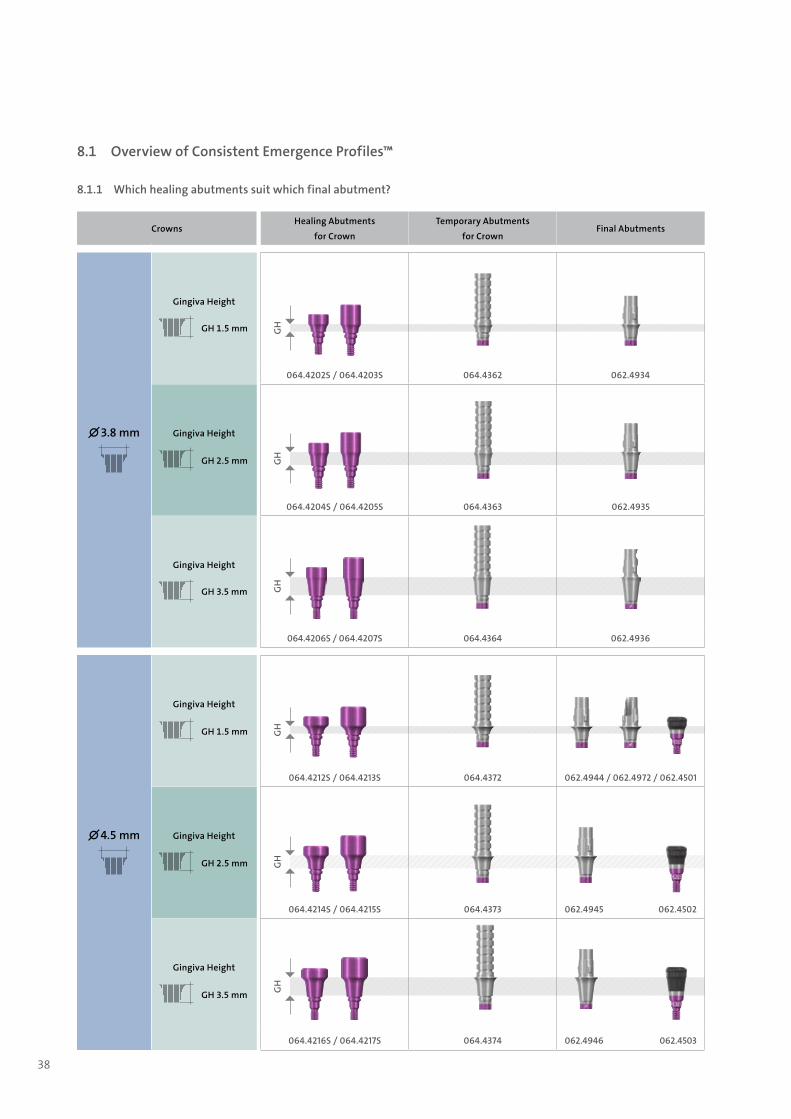
8.1 Overview of Consistent Emergence Profiles™
8.1.1 Which healing abutments suit which final abutment?
GH
GH
GH
GH
GH
GH
CrownsHealing Abutments
for Crown
Temporary Abutments
for CrownFinal Abutments
∅ 3.8 mm
Gingiva Height
GH 1.5 mm
064.4202S / 064.4203S 064.4362 062.4934
Gingiva Height
GH 2.5 mm
064.4204S / 064.4205S 064.4363 062.4935
Gingiva Height
GH 3.5 mm
064.4206S / 064.4207S 064.4364 062.4936
∅ 4.5 mm
Gingiva Height
GH 1.5 mm
064.4212S / 064.4213S 064.4372 062.4944 / 062.4972 / 062.4501
Gingiva Height
GH 2.5 mm
064.4214S / 064.4215S 064.4373 062.4945 062.4502
Gingiva Height
GH 3.5 mm
064.4216S / 064.4217S 064.4374 062.4946 062.4503
702115.indd 38 18/12/2018 09:27

39
GH
GH
GH
GH
GH
BridgesHealing Abutments
for BridgesTemporary Abutments
for BridgesFinal Abutments
Bridges
∅ 4.5 mm Gingiva Height
GH 1.5 mm
064.4232S / 064.4233S 064.4352 062.4961
CrownsHealing Abutments
for Crown
Temporary Abutments
for CrownFinal Abutments
∅ 6.0 mm
Gingiva Height
GH 2.5 mm
064.4224S / 064.4225S 064.4382 062.4103 / 062.4153
Gingiva Height
GH 3.5 mm
064.4226S / 064.422S7 064.4383 062.4104 / 062.4154
∅ 5.5 mm
Gingiva Height
GH 0.75 mm
064.8201S / 064.8202S / 064.8203S / 064.8204S
064.4391 062.4953
Gingiva Height
GH 1.5 mm
064.8212S / 064.8213S / 064.8214S / 064.8215S
064.4392 062.4954 062.4971
702115.indd 39 18/12/2018 09:27
40
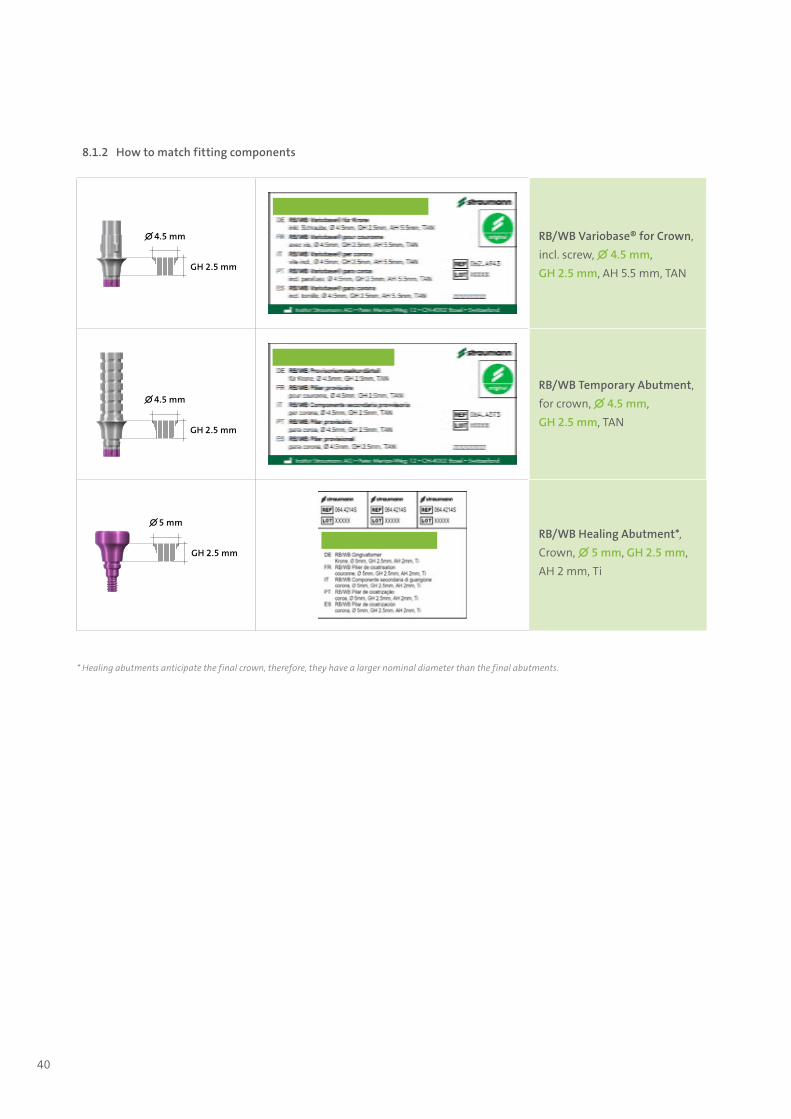
8.1.2 How to match fitting components
∅ 4.5 mm
GH 2.5 mm
RB/WB Variobase® for Crown,incl. screw, ∅ 4.5 mm, GH 2.5 mm, AH 5.5 mm, TAN
∅ 4.5 mm
GH 2.5 mm
RB/WB Temporary Abutment,for crown, ∅ 4.5 mm, GH 2.5 mm, TAN
∅ 5 mm
GH 2.5 mm
RB/WB Healing Abutment*,Crown, ∅ 5 mm, GH 2.5 mm, AH 2 mm, Ti
* Healing abutments anticipate the final crown, therefore, they have a larger nominal diameter than the final abutments.
702115.indd 40 18/12/2018 09:27
41
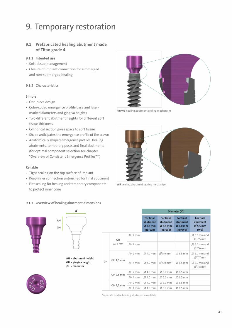
9.1 Prefabricated healing abutment made of Titan grade 4
9.1.1 Intented use ѹ Soft tissue management ѹ Closure of implant connection for submerged
and non-submerged healing
9.1.2 Characteristics
Simple ѹ One-piece design ѹ Color-coded emergence profile base and laser-
marked diameters and gingiva heights ѹ Two different abutment heights for different soft
tissue thickness ѹ Cylindrical section gives space to soft tissue ѹ Shape anticipates the emergence profile of the crown ѹ Anatomically shaped emergence profiles, healing
abutments, temporary posts and final abutments (for optimal component selection see chapter “Overview of Consistent Emergence Profiles™”)
Reliable ѹ Tight sealing on the top surface of implant ѹ Keep inner connection untouched for final abutment ѹ Flat sealing for healing and temporary components
to protect inner cone
9. Temporary restoration
RB/WB healing abutment sealing mechanism
WB healing abutment sealing mechanism
∅
GH
AH
AH = abutment heightGH = gingiva height∅ = diameter
Diameter (∅)
For final abutment ∅ 3.8 mm (RB/WB)
For final abutment ∅ 4.5 mm (RB/WB)
For final abutment ∅ 6.0 mm (RB/WB)
For final abutment ∅ 5.5 mm
(WB)
GH
GH 0,75 mm
AH 2 mm ∅ 6.0 mm and ∅ 7.5 mm
AH 4 mm ∅ 6.0 mm and ∅ 7.6 mm
GH 1,5 mm
AH 2 mm ∅ 4.0 mm ∅ 5.0 mm* ∅ 6.5 mm ∅ 6.0 mm and ∅ 7.7 mm
AH 4 mm ∅ 4.0 mm ∅ 5.0 mm* ∅ 6.5 mm ∅ 6.0 mm and ∅ 7.8 mm
GH 2,5 mmAH 2 mm ∅ 4.0 mm ∅ 5.0 mm ∅ 6.5 mm
AH 4 mm ∅ 4.0 mm ∅ 5.0 mm ∅ 6.5 mm
GH 3,5 mmAH 2 mm ∅ 4.0 mm ∅ 5.0 mm ∅ 6.5 mm
AH 4 mm ∅ 4.0 mm ∅ 5.0 mm ∅ 6.5 mm
*separate bridge healing abutments available
9.1.3 Overview of healing abutment dimensions
702115.indd 41 18/12/2018 09:27
42
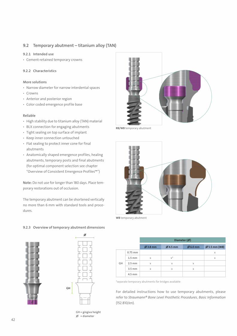
9.2 Temporary abutment – titanium alloy (TAN)
9.2.1 Intended use ѹ Cement-retained temporary crowns
9.2.2 Characteristics
More solutions ѹ Narrow diameter for narrow interdental spaces ѹ Crowns ѹ Anterior and posterior region ѹ Color coded emergence profile base
Reliable ѹ High stability due to titanium alloy (TAN) material ѹ BLX connection for engaging abutments ѹ Tight sealing on top surface of implant ѹ Keep inner connection untouched ѹ Flat sealing to protect inner cone for final
abutments ѹ Anatomically shaped emergence profiles, healing
abutments, temporary posts and final abutments (for optimal component selection see chapter “Overview of Consistent Emergence Profiles™”)
Note: Do not use for longer than 180 days. Place tem-porary restorations out of occlusion.
The temporary abutment can be shortened vertically no more than 6 mm with standard tools and proce-dures.
RB/WB temporary abutment
WB temporary abutment
9.2.3 Overview of temporary abutment dimensions
GH
∅
GH = gingiva height∅ = diameter
Diameter (∅)
∅ 3.8 mm ∅ 4.5 mm ∅ 6.0 mm ∅ 5.5 mm (WB)
GH
0.75 mm x
1.5 mm x x* x
2.5 mm x x x
3.5 mm x x x
4.5 mm
*separate temporary abutments for bridges available
For detailed instructions how to use temporary abutments, please refer to Straumann® Bone Level Prosthetic Procedures, Basic Information (152.810/en).
702115.indd 42 18/12/2018 09:27
43
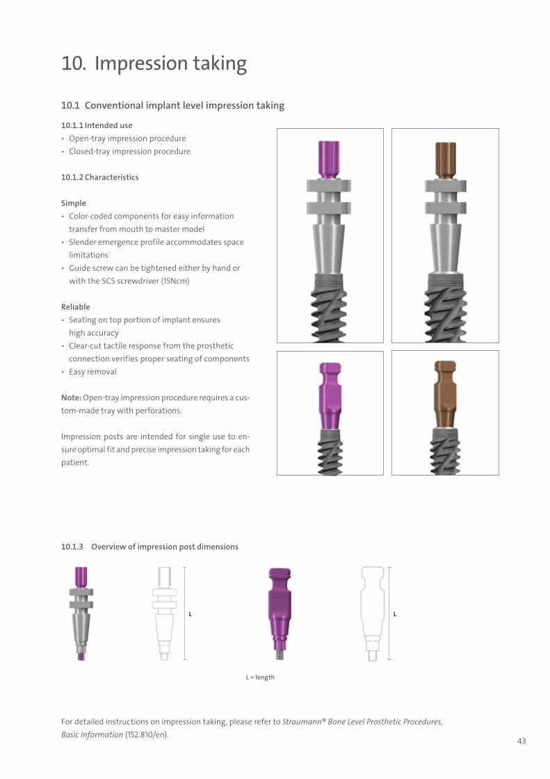
10. Impression taking
10.1 Conventional implant level impression taking
10.1.1 Intended use ѹ Open-tray impression procedure ѹ Closed-tray impression procedure
10.1.2 Characteristics
Simple ѹ Color-coded components for easy information
transfer from mouth to master model ѹ Slender emergence profile accommodates space
limitations ѹ Guide screw can be tightened either by hand or
with the SCS screwdriver (15Ncm)
Reliable ѹ Seating on top portion of implant ensures
high accuracy ѹ Clear-cut tactile response from the prosthetic
connection verifies proper seating of components ѹ Easy removal
Note: Open-tray impression procedure requires a cus-tom-made tray with perforations.
Impression posts are intended for single use to en-sure optimal fit and precise impression taking for each patient.
L = length
L L
10.1.3 Overview of impression post dimensions
For detailed instructions on impression taking, please refer to Straumann® Bone Level Prosthetic Procedures, Basic Information (152.810/en).
702115.indd 43 18/12/2018 09:27

44
10.2 Digital impressions: Straumann® CARES® Mono Scanbody
BLX
CARES® RB / WB Mono Scanbody, for implant-level scanning
CARES® Mono Scanbody for Screw-retained Abutment, for abutment level, ∅ 4.6 mm, PEEK / TAN
Compatibility
Number of components 2: scanbody, self-retaining screw
Component/materialScanbody: polymer (PEEK)
Screw: titanium alloy (TAN)
10.2.1 Product descriptionThe Straumann® scanbodies represent the position and orientation of the respective dental implant, analog or abutment in CADCAM scanning procedures. This helps the CADCAM software to correctly align the subsequent CADCAM resto-rations.
For detailed instructions how to use the CARES® Mono Scanbody, please refer to Step-by-step instructions on the intraoral scanbodies, Basic Information (702063/en).
For detailed instructions how to take conventional impression, please refer to Straumann® Bone Level Prosthetic Procedures, Basic Information (152.810/en).
702115.indd 44 18/12/2018 09:27

45
11. Final restoration
11.1 Straumann® Screw-retained Abutments
11.2.1 Intended use ѹ Screw-retained multi-unit as well as single-unit
restorations at abutment level ѹ Full-arch restorations at abutment-level, screw-
retained as well as removable
11.1.2 Characteristics
Sleek design and clear portfolio ѹ Same low abutment connector design allows
streamlined tertiary components over all implant types
ѹ Abutment angulations of 0°, 17° and 30° ѹ Abutment design allows both multi-unit and single-
unit restorations ѹ Sterile packed for immediate use ѹ Different gingiva heights of 1.5 mm, 2.5 mm,
3.5 mm and 4.5 mm ѹ Simplified handling with the BLX connection ѹ Straight abutments in one-piece design
AH = abutment heightGH = gingiva height∅ = diameterCA = abutment connectora = angle
∅ ∅
CA22°
AH
GH
AH
GH
∅ 4.6
∅
AH
GH
a 17° a 30°
11.1.3 Overview of screw-retained abutment dimensions
Diameter (∅)
∅ 4.6 mm
Angle 0° 17° 30°
GH
0.75 mm
1.5 mm x
2.5 mm x x x
3.5 mm x x x
4.5 mm x x x
702115.indd 45 18/12/2018 09:27
46
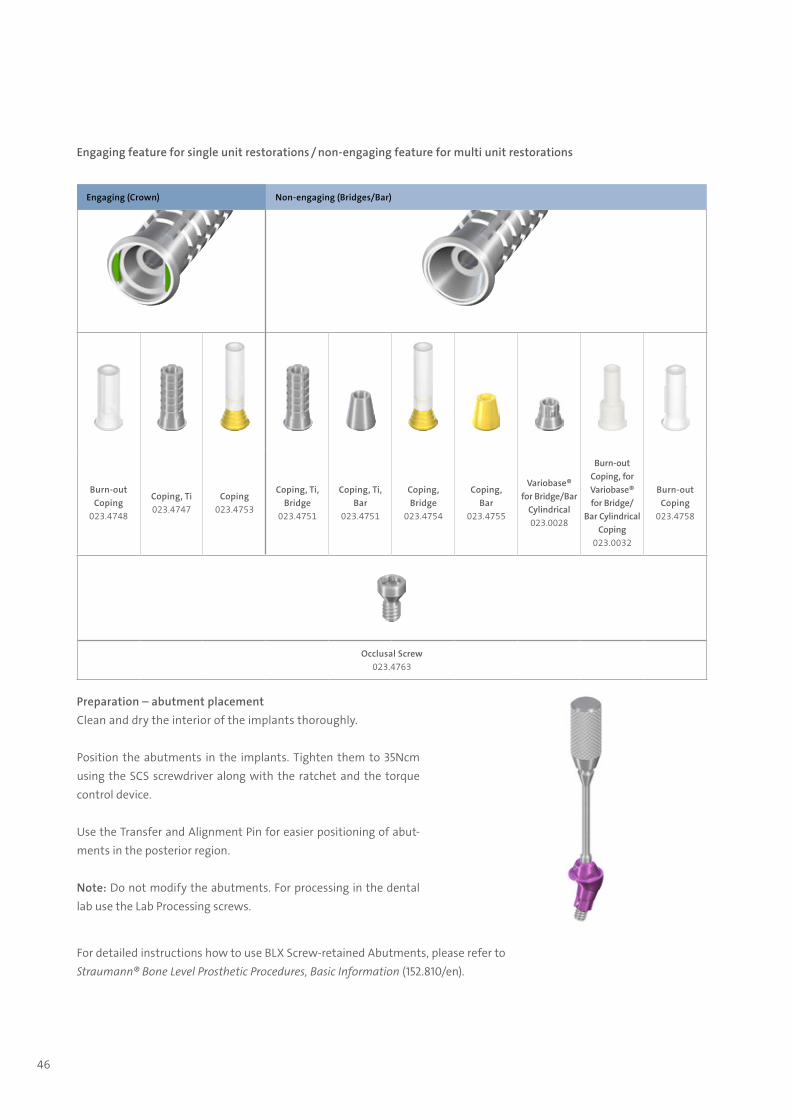
Engaging feature for single unit restorations / non-engaging feature for multi unit restorations
Engaging (Crown) Non-engaging (Bridges/Bar)
Burn-out Coping
023.4748
Coping, Ti023.4747
Coping023.4753
Coping, Ti, Bridge
023.4751
Coping, Ti, Bar
023.4751
Coping, Bridge
023.4754
Coping, Bar
023.4755
Variobase® for Bridge/Bar
Cylindrical023.0028
Burn-out Coping, for Variobase® for Bridge/
Bar Cylindrical Coping
023.0032
Burn-out Coping
023.4758
Occlusal Screw023.4763
Preparation – abutment placementClean and dry the interior of the implants thoroughly.
Position the abutments in the implants. Tighten them to 35Ncm using the SCS screwdriver along with the ratchet and the torque control device.
Use the Transfer and Alignment Pin for easier positioning of abut-ments in the posterior region.
Note: Do not modify the abutments. For processing in the dental lab use the Lab Processing screws.
For detailed instructions how to use BLX Screw-retained Abutments, please refer to Straumann® Bone Level Prosthetic Procedures, Basic Information (152.810/en).
702115.indd 46 18/12/2018 09:27
47
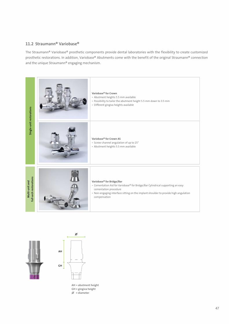
11.2 Straumann® Variobase®
The Straumann® Variobase® prosthetic components provide dental laboratories with the flexibility to create customized prosthetic restorations. In addition, Variobase® Abutments come with the benefit of the original Straumann® connection and the unique Straumann® engaging mechanism.
∅
GH
AH
AH = abutment heightGH = gingiva height∅ = diameter
SIng
le-u
nit r
esto
ratio
ns
Variobase® for Crown ▪ Abutment heights 5.5 mm available ▪ Possibility to tailor the abutment height 5.5 mm down to 3.5 mm ▪ Different gingiva heights available
Variobase® for Crown AS ▪ Screw-channel angulation of up to 25° ▪ Abutment heights 5.5 mm available
Mul
ti-un
it a
nd
full-
arch
rest
orat
ions
Variobase® for Bridge/Bar ▪ Cementation Aid for Variobase® for Bridge/Bar Cylindrical supporting an easy cementation procedure
▪ Non-engaging interface sitting on the implant shoulder to provide high angulation compensation
702115.indd 47 18/12/2018 09:27
48
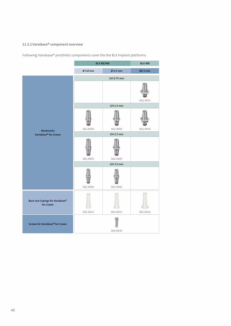
11.2.1 Variobase® component overview
Following Variobase® prosthetic components cover the the BLX Implant platforms:
BLX RB/WB BLX WB
Ø 3.8 mm Ø 4.5 mm Ø5.5 mm
AbutmentsVariobase® for Crown
GH 0.75 mm
062.4953
GH 1.5 mm
062.4934 062.4944 062.4954
GH 2.5 mm
062.4935 062.4945
GH 3.5 mm
062.4936 062.4946
Burn-out Copings for Variobase® for Crown
065.0014 065.0015 065.0016
Screws for Variobase® for Crown
065.0036
702115.indd 48 18/12/2018 09:27

49
BLX RB/WB BLX WB
Ø 3.8 mm Ø 4.5 mm Ø5.5 mm
AbutmentsVariobase® for Crown AS
GH 1.5 mm
062.4972 062.4971
Burn-out Copings for Variobase® for Crown AS
065.0018 065.0019
Screws for Variobase® for Crown AS
065.0037
Ø 3.8 mm Ø 4.5 mm Ø5.5 mm
Abutments Variobase® for Bridge/Bar Cylindrical
GH 1.5 mm
062.4961
Cementation Aid
160.3
Burn-out Copings for Variobase® for Bridge/Bar Cylindrical
065.0017 / 065.0017V4
Screws for Variobase® for Bridge/Bar Cylindrical
065.0036
For detailed instructions on how to use Variobase® Abutments, please refer to Straumann® Variobase® Basic Information (490.062/en).
702115.indd 49 18/12/2018 09:27

50
11.3 Straumann® Anatomic Abutments
11.3.1 Intended use ѹ Cement-retained restorations
11.3.2 Characteristics
Simple and Reliable ѹ Less grinding necessary due to prepared mucosa
margins ѹ Adaptation to natural soft tissue contour due to
prepared mucosa margins at different heights ѹ Oval shape resembles emergence profile of a
natural tooth ѹ 0° and 17° ѹ Anatomically shaped emergence profiles, healing
abutments, temporary posts and final abutments (for optimal component selection see chapter “Overview of Consistent Emergence Profiles™”)
A minimum height of 3 mm above the mucosa margin of the abutment must be maintained in order to maintain proper stability of the abutment. The cement margin must not be more than 2 mm below the mucosa. Use a new basal screw for the final insertion of the abutment.
11.3.3 Overview of anatomic abutment dimensions
GH
∅
GH
∅
17°
GH = gingiva height ∅ = diameter
For detailed instructions how to use BLX Anatomic abutments, please refer to Straumann® Bone Level Prosthetic Procedures, Basic Information (152.810/en).
Diameter (∅)
∅ 6 mm
Angle 0° 17°
GH
0.75 mm
1.5 mm
2.5 mm X X
3.5 mm X X
4.5 mm
702115.indd 50 18/12/2018 09:27
51
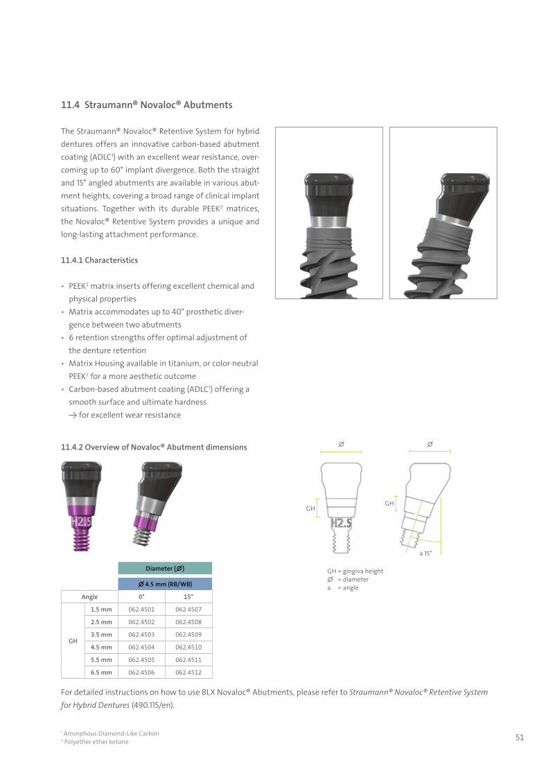
11.4 Straumann® Novaloc® Abutments
The Straumann® Novaloc® Retentive System for hybrid dentures offers an innovative carbon-based abutment coating (ADLC1) with an excellent wear resistance, over-coming up to 60° implant divergence. Both the straight and 15° angled abutments are available in various abut-ment heights, covering a broad range of clinical implant situations. Together with its durable PEEK2 matrices, the Novaloc® Retentive System provides a unique and long-lasting attachment performance.
11.4.1 Characteristics
ѹ PEEK2 matrix inserts offering excellent chemical and physical properties
ѹ Matrix accommodates up to 40° prosthetic diver-gence between two abutments
ѹ 6 retention strengths offer optimal adjustment of the denture retention
ѹ Matrix Housing available in titanium, or color-neutral PEEK2 for a more aesthetic outcome
ѹ Carbon-based abutment coating (ADLC1) offering a smooth surface and ultimate hardness → for excellent wear resistance
1 Amorphous Diamond-Like Carbon2 Polyether ether ketone
11.4.2 Overview of Novaloc® Abutment dimensions
For detailed instructions on how to use BLX Novaloc® Abutments, please refer to Straumann® Novaloc® Retentive System for Hybrid Dentures (490.115/en).
Diameter (∅)
∅ 4.5 mm (RB/WB)
Angle 0° 15°
GH
1.5 mm 062.4501 062.4507
2.5 mm 062.4502 062.4508
3.5 mm 062.4503 062.4509
4.5 mm 062.4504 062.4510
5.5 mm 062.4505 062.4511
6.5 mm 062.4506 062.4512
GH = gingiva height∅ = diametera = angle
∅
GHGH
∅
a 15°
702115.indd 51 18/12/2018 09:27
52
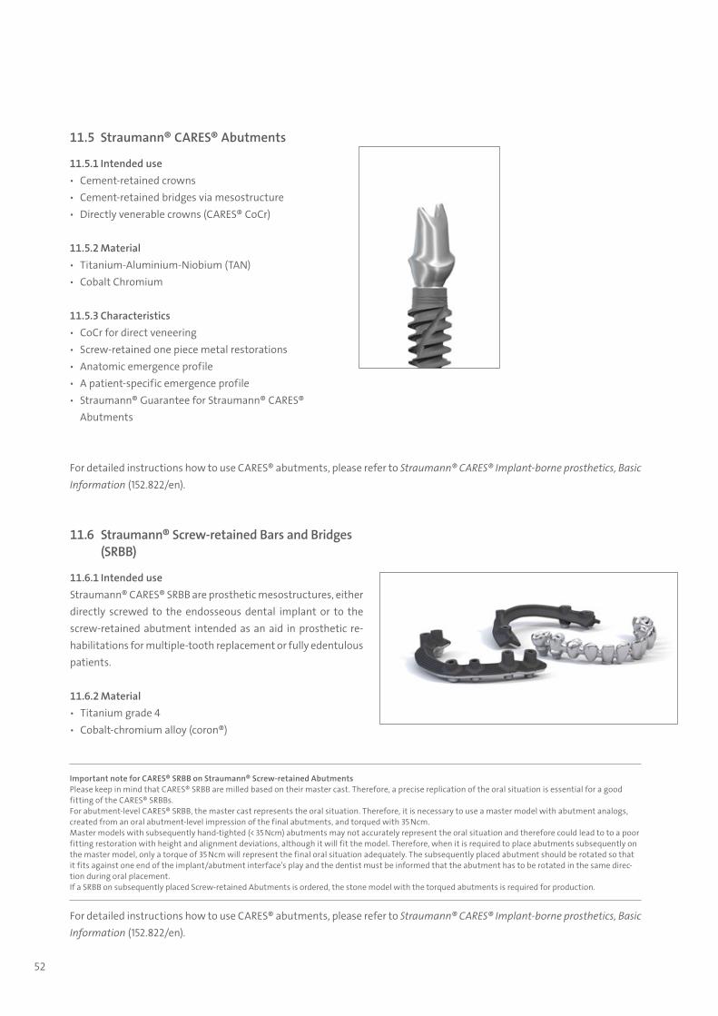
11.5 Straumann® CARES® Abutments
11.5.1 Intended use ѹ Cement-retained crowns ѹ Cement-retained bridges via mesostructure ѹ Directly venerable crowns (CARES® CoCr)
11.5.2 Material ѹ Titanium-Aluminium-Niobium (TAN) ѹ Cobalt Chromium
11.5.3 Characteristics ѹ CoCr for direct veneering ѹ Screw-retained one piece metal restorations ѹ Anatomic emergence profile ѹ A patient-specific emergence profile ѹ Straumann® Guarantee for Straumann® CARES®
Abutments
For detailed instructions how to use CARES® abutments, please refer to Straumann® CARES® Implant-borne prosthetics, Basic Information (152.822/en).
For detailed instructions how to use CARES® abutments, please refer to Straumann® CARES® Implant-borne prosthetics, Basic Information (152.822/en).
11.6 Straumann® Screw-retained Bars and Bridges (SRBB)
11.6.1 Intended use Straumann® CARES® SRBB are prosthetic mesostructures, either directly screwed to the endosseous dental implant or to the screw-retained abutment intended as an aid in prosthetic re-habilitations for multiple-tooth replacement or fully edentulous patients.
11.6.2 Material ѹ Titanium grade 4 ѹ Cobalt-chromium alloy (coron®)
Important note for CARES® SRBB on Straumann® Screw-retained AbutmentsPlease keep in mind that CARES® SRBB are milled based on their master cast. Therefore, a precise replication of the oral situation is essential for a good fitting of the CARES® SRBBs.For abutment-level CARES® SRBB, the master cast represents the oral situation. Therefore, it is necessary to use a master model with abutment analogs, created from an oral abutment-level impression of the final abutments, and torqued with 35 Ncm.Master models with subsequently hand-tighted (< 35 Ncm) abutments may not accurately represent the oral situation and therefore could lead to to a poor fitting restoration with height and alignment deviations, although it will fit the model. Therefore, when it is required to place abutments subsequently on the master model, only a torque of 35 Ncm will represent the final oral situation adequately. The subsequently placed abutment should be rotated so that it fits against one end of the implant/abutment interface’s play and the dentist must be informed that the abutment has to be rotated in the same direc-tion during oral placement.If a SRBB on subsequently placed Screw-retained Abutments is ordered, the stone model with the torqued abutments is required for production.
702115.indd 52 18/12/2018 09:27
53
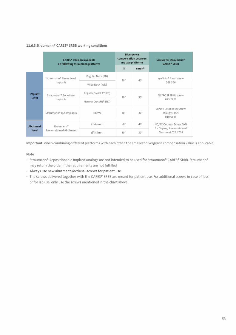
11.6.3 Straumann® CARES® SRBB working conditions
Important: when combining different platforms with each other, the smallest divergence compensation value is applicable.
Note ѹ Straumann® Repositionable Implant Analogs are not intended to be used for Straumann® CARES® SRBB. Straumann®
may return the order if the requirements are not fulfilled ѹ Always use new abutment-/occlusal-screws for patient use ѹ The screws delivered together with the CARES® SRBB are meant for patient use. For additional screws in case of loss
or for lab use, only use the screws mentioned in the chart above
CARES® SRBB are available on following Straumann platforms
Divergence compensation between
any two platformsScrews for Straumann®
CARES® SRBB
Ti coron®
Implant Level
Straumann® Tissue Level Implants
Regular Neck (RN)50° 40°
synOcta® Basal screw048.356
Wide Neck (WN)
Straumann® Bone Level Implants
Regular CrossFit® (RC)30° 30°
NC/RC SRBB BL screw025.2926
Narrow CrossFit® (NC)
Straumann® BLX Implants RB/WB 30° 30°RB/WB SRBB Basal Screw,
straight, TAN010.6145
Abutment level
Straumann® Screw-retained Abutment
∅ 4.6 mm 50° 40° NC/RC Occlusal Screw, TAN for Coping, Screw-retained
Abutment 023.4763∅ 3.5 mm 30° 30°
702115.indd 53 18/12/2018 09:27
54
11.7 Straumann® CARES® Scan & Shape
CARES® Scan & Shape lets you benefit from the knowledge and experience of a highly trained team of CADCAM dental experts to provide a tailored design service. The concept is designed to ensure the best possible fit of the final restorations. You can now order via Scan & Shape: customized abutments, CARES® Screw-retained Bars and Bridges (SRBB), CARES® X-Stream™ Restorative Options and tooth-borne restorations.
Whether you’re expanding your business or you have an existing staff member out for an ex-tended period of time, we’re open 24/7 so you don’t have to be.
Ordering process ѹ The CARES® Scan & Shape online ordering platform provides a one-stop-shop for all your
customized prosthetics ѹ Send digital files using our open STL-Files upload* service or ѹ Traditional workflows – send us your master cast and/or wax-up model*
Premium Straumann® Service ѹ Custom-made abutment design ѹ Straumann® Original connection ѹ Straumann® precision fit between implant and abutment
Compatible solutions ѹ Provides a streamlined “one-stop shop” and an efficient digital workflow ѹ Benefit from Straumann® CARES® Scan & Shape services for customized abutments and
CARES® X-Stream™ single restoration for all major implant platforms
Note: For detailed information on all Straumann® CARES® offerings, please see Straumann® CARES® Scan & Shape, Basic Information (490.190/en).
* Not all products, services and workflows are available in all countries. Please contact your sales representative for a detailed overview.
702115.indd 54 18/12/2018 09:27
55
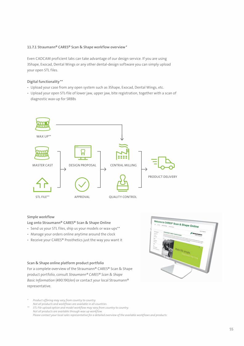
11.7.1 Straumann® CARES® Scan & Shape workflow overview *
Even CADCAM proficient labs can take advantage of our design service. If you are using 3Shape, Exocad, Dental Wings or any other dental-design software you can simply upload your open STL files.
Digital functionality ** ѹ Upload your case from any open system such as 3Shape, Exocad, Dental Wings, etc. ѹ Upload your open STL-file of lower jaw, upper jaw, bite registration, together with a scan of
diagnostic wax-up for SRBBs
* Product offering may vary from country to country.Not all products and workflows are available in all countries.
** STL File upload option and model workflow may vary from country to country.Not all products are available through wax up workflow.Please contact your local sales representative for a detailed overview of the available workflows and products.
PRODUCT DELIVERY
QUALITY CONTROL
CENTRAL MILLING
APPROVAL
DESIGN PROPOSAL
STL FILE**
MASTER CAST
WAX UP**
Simple workflowLog onto Straumann® CARES® Scan & Shape Online ѹ Send us your STL files, ship us your models or wax-ups** ѹ Manage your orders online anytime around the clock ѹ Receive your CARES® Prosthetics just the way you want it
Scan & Shape online platform product portfolioFor a complete overview of the Straumann® CARES® Scan & Shape product portfolio, consult Straumann® CARES® Scan & ShapeBasic Information (490.190/en) or contact your local Straumann® representative.
702115.indd 55 18/12/2018 09:27
56
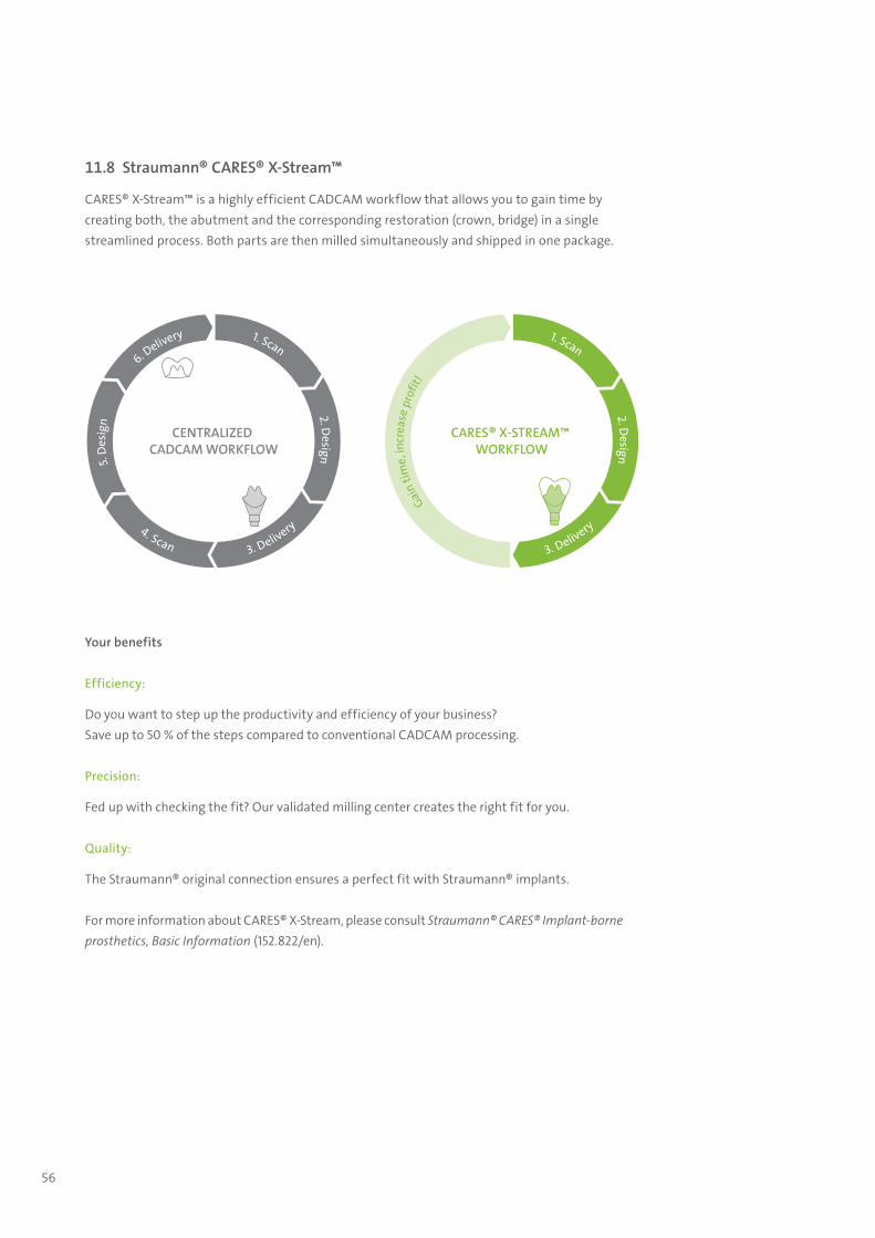
11.8 Straumann® CARES® X-Stream™
CARES® X-Stream™ is a highly efficient CADCAM workflow that allows you to gain time by creating both, the abutment and the corresponding restoration (crown, bridge) in a single streamlined process. Both parts are then milled simultaneously and shipped in one package.
CENTRALIZED CADCAM WORKFLOW
1. Scan
4. Scan 3. Delivery
6. Delivery
5. D
esig
n
2. Design
CARES® X-STREAM™ WORKFLOW
1. Scan
3. Delivery
Gain
time,
incr
ease
pro
fit!
2. Design
Your benefits
Efficiency:
Do you want to step up the productivity and efficiency of your business? Save up to 50 % of the steps compared to conventional CADCAM processing.
Precision:
Fed up with checking the fit? Our validated milling center creates the right fit for you.
Quality:
The Straumann® original connection ensures a perfect fit with Straumann® implants.
For more information about CARES® X-Stream, please consult Straumann® CARES® Implant-borne prosthetics, Basic Information (152.822/en).
702115.indd 56 18/12/2018 09:27
57
Instruments with high cutting performance are a basic requirement for successful implantation. Therefore, careful treat-ment of all instruments is of the outmost importance. Even slight damage, for instance to the drill tips, impairs cutting performance and thus the clinical result. With correct and careful care, the high quality of the material and excellent exe-cution ensure that the cutting instruments (drills) can be used repeatedly (up to a maximum of ten times is recommended).
If possible, an automated method (cleaning and disinfection unit) should be used for cleaning and disinfection because of its higher effectiveness and reproducibility. A manual method should be used only if an automated method is not available.
The BLX Surgical Cassette allows for automated reprocessing of the BLX surgical instruments in order to simplify the repro-cessing workflow and to ensure optimal cleaning and care.
During surgeryUse each instrument only for its intended purpose. Contaminated instruments can be placed back to the designated space in the BLX surgical cassette. Damaged and / or blunt instruments must be sorted out and disinfected, cleaned and disposed of separately.
12.1 Pretreatment
Pretreatment is required prior to both manual and automated cleaning! Never let surgical residues (blood, secretions, tissue residues) dry on an instrument; clean immediately after surgery.Place the instruments in a water bath or a disinfectant solution. Thoroughly clean off incrustations with soft brushes only. Disassemble multi-piece instruments, clean cavities and lumens especially well. If applicable: Sort the pretreated instruments into the BLX surgical cassette.
It is important to use protective clothing while cleaning contaminated instruments. Always wear protective glasses, face mask, gloves, waterproof qown, etc. for your own safety during all activities.
Please note that the disinfectant used in pretreatment serves only for your own protection and cannot replace the disinfec-tion step to be performed later, after cleaning.
12. Cleaning and care of BLX surgical instruments and the BLX surgical cassette
702115.indd 57 18/12/2018 09:27
58
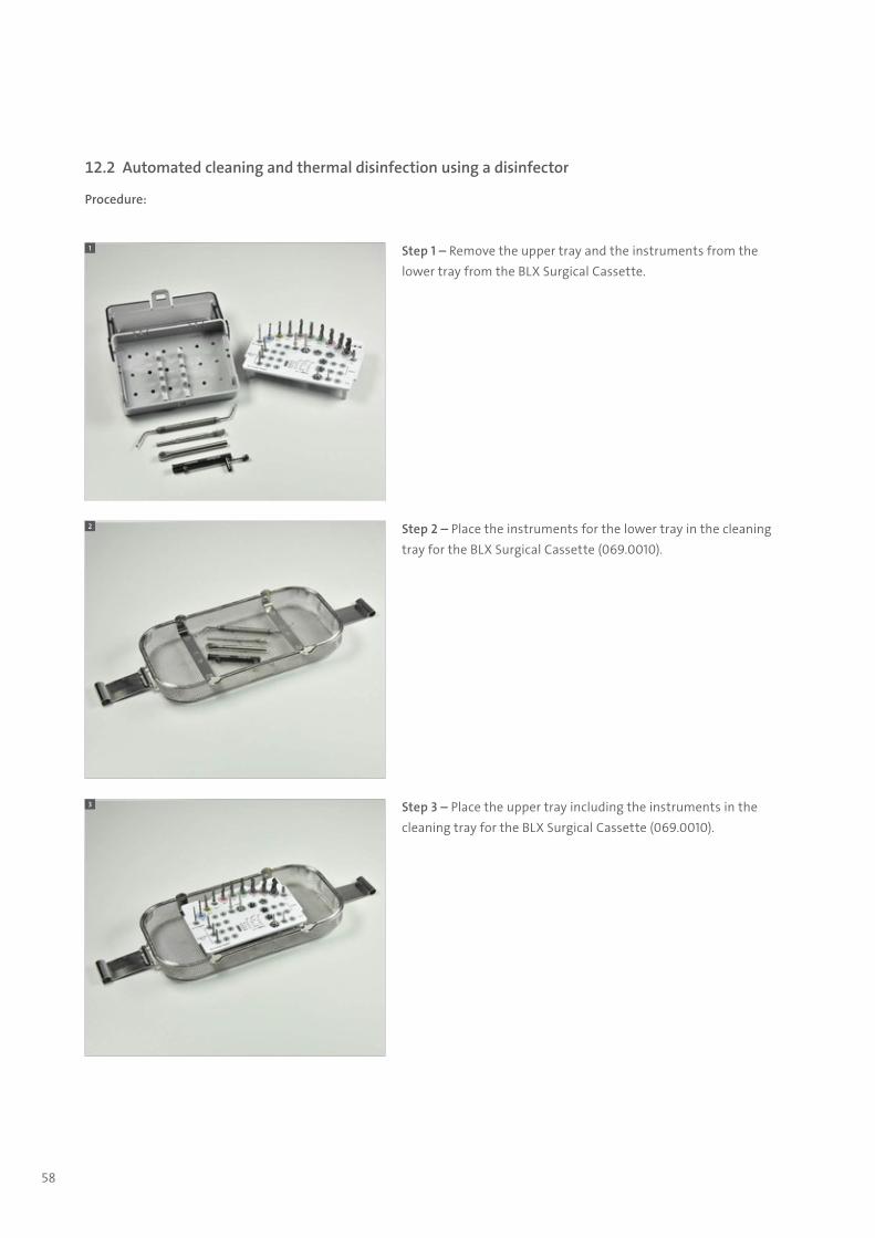
12.2 Automated cleaning and thermal disinfection using a disinfector
Procedure:
Step 1 – Remove the upper tray and the instruments from the lower tray from the BLX Surgical Cassette.
1
Step 2 – Place the instruments for the lower tray in the cleaning tray for the BLX Surgical Cassette (069.0010).
2
Step 3 – Place the upper tray including the instruments in the cleaning tray for the BLX Surgical Cassette (069.0010).
3
702115.indd 58 18/12/2018 09:27
59
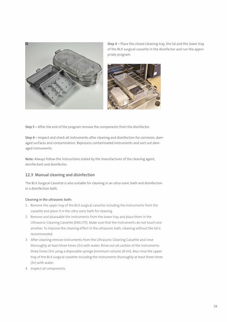
Step 5 – After the end of the program remove the components from the disinfector.
Step 6 – Inspect and check all instruments after cleaning and disinfection for corrosion, dam-aged surfaces and contamination. Reprocess contaminated instruments and sort out dam-aged instruments.
Note: Always follow the instructions stated by the manufacturer of the cleaning agent, disinfectant and disinfector.
12.3 Manual cleaning and disinfection
The BLX Surgical Cassette is also suitable for cleaning in an ultra-sonic bath and disinfection in a disinfection bath.
Cleaning in the ultrasonic bath:
1. Remove the upper tray of the BLX surgical cassette including the instruments from the
cassette and place it in the ultra sonic bath for cleaning.
2. Remove and disassable the instruments from the lower tray and place them in the
Ultrasonic Cleaning Cassette (040.175). Make sure that the instruments do not touch one
another. To improve the cleaning effect in the ultrasonic bath, cleaning without the lid is
recommended.
3. After cleaning remove instruments from the Ultrasonic Cleaning Cassette and rinse
thoroughly at least three times (3×) with water. Rinse out all cavities of the instruments
three times (3×) using a disposable syringe (minimum volume 20 ml). Also rinse the upper
tray of the BLX surgical cassette including the instruments thoroughly at least three times
(3×) with water.
4. Inspect all components.
Step 4 – Place the closed cleaning tray, the lid and the lower tray of the BLX surgical cassette in the disinfector and run the appro-priate program.
4
702115.indd 59 18/12/2018 09:27

60
Disinfection:
1. Place the components for the specified action time in the disinfection bath. Ensure
that the instruments are sufficiently covered by the disinfection solution and that the
instruments do not touch each other.
2. Rinse out all cavities of the components three times (3×) at the beginning or at the end of
the action time using a disposable syringe (minimum volume 20 ml).
3. Then remove the components from the disinfection bath and rinse them thoroughly with
water at least five times (5×).
4. Rinse out all cavities of the instruments five times (5×) using a disposable syringe
(minimum volume 20 ml).
5. Dry the components inside/out with filtered compressed air.
6. Pack the components as quickly as possible after removal. If additional drying is necessary,
dry in a clean location.
12.4 Sterilization
Step 1 – Reassemble all instrumentsReassemble the BLX Surgical Cassette and replace missing devices by properly cleaned and disinfected ones.
Step 2 – PackagingPack the instruments or the sterilization cassettes singly or doubly in disposable sterilization packaging corresponding to the following requirements:
ѹ Suitable for steam sterilization (temperature resistance up to at least 138°C (280°F), sufficient steam permeability)
ѹ Sufficient protection of the instruments or sterilization packaging against mechanical damage
Note: An indicator strip with the date of the sterilization, the expiration date and the operator should be affixed to every sterilization packaging. This will help to indicate if, when and by whom the material was sterilized.
Step 3 – Steam sterilizationSterilization Parameter EuropeFractionated vacuum. Assembled cassette at least 3 min. at 132°C (270°F) up to 134°C (273°F), drying time 20 min.
Step 4The sterile BLX Surgical Cassettes must be stored dry and free of dust in the sterilization pack-aging after sterilization.
For further information regarding cleaning and care of instruments please refer to the brochure Straumann® Surgical and Prosthetic Instruments, Care and Maintenance (152.008/en) available on ifu.straumann.com -> “General product information”
702115.indd 60 18/12/2018 09:27

Notes
702115.indd 61 18/12/2018 09:27

International HeadquartersInstitut Straumann AGPeter Merian-Weg 12CH-4002 Basel, SwitzerlandPhone +41 (0)61 965 11 11Fax +41 (0)61 965 11 01www.straumann.com
© Institut Straumann AG, 2018. All rights reserved.Straumann® and/or other trademarks and logos from Straumann® mentioned herein are the trademarks or registered trademarks of Straumann Holding AG and/or its affiliates.
70
2.11
5/en
/D/0
3 11
/18
702115.indd 62 18/12/2018 09:27