basic field manual volume iii-1932
TRANSCRIPT

8/22/2019 Basic Field Manual Volume III-1932
http://slidepdf.com/reader/full/basic-field-manual-volume-iii-1932 1/203
BASIC FIELD MANUAL
Volume III
BASIC WEAPONS
PART THREE
MACHINE-GUN COMPANY
PREP ARED UNDER DIRECTION OF THU
CHIEF OF INFANTRY
1932
UNITED STATES
GOVERNMENT PRINTING OFFICE
WASJlINGTON : 1932
For lillIe by the Superintendent or I>ocuments. Washington, D. C.
'J'rlce'20 0011&8
8/22/2019 Basic Field Manual Volume III-1932
http://slidepdf.com/reader/full/basic-field-manual-volume-iii-1932 2/203
OcnCTal.
OFFICIAL:
C. II. BRIDGES, ,J["jOT OenfTal,
Tile Adjutant
'VAR DEPARTMENT,
'VASIlI;\;OTON, June 10, 19,1.?
Part Three, Machine-gun COlllvany, Dasic ]'ipld ManulI'
Volume III,' Basic Wpallons, Is vuhlished for the informatIJl
and guidance of all concerned.
[A. G. 062.11 (4-13-31).] .'
By ORDER OF TIlE SECUE..'TARY O}' "~AU: ',•.
DOUGLAS MAcAHTIIUH, .
General,
Chlct of StulTr
Ii
Lf'
I
",'
•••

8/22/2019 Basic Field Manual Volume III-1932
http://slidepdf.com/reader/full/basic-field-manual-volume-iii-1932 3/203
LIST OF FIELD MANUALS
A MANUAL FOR COMMANDERS OF LARGE UNITS. (M. C. L. U.)
Vol. I. O/lcratlon8.-A guide for commanders aod staffs for tactical
operations of large units.
II. Administratloro.-A guide for the administration of large units
in a theater of operations.
r' STAFF OFFICERS' FIELD MANUAL. (8 . O. F. M.)
Stal! prlnelpll's and functions appllcalJ1e to the statf~ of all units,
togl'ther with pertinent rl'ference data
BASIC FIELD MANUALS. (8. F. M.)
Training, admlnlHtrativ<', and reference data applicable to more than one
arm, with specllll reference to the smaller units
Vol. I. Fidel Service Pocketbook. (F. S. r.)-The individual.II. Infantrv Drill Regulations. (I. D. R.)-Drlll, dllmlOunted c('re-
monleM and inspections; the infantry pack, dlHplay of equip-
ment, and tent drlll.
III. Basio Weapon8. (n. W.)-Marksmanshlp and mechanical train-
ing of the rltle, automatic rltle, pilltol, machine gun, 37-mm.
gun, 3-lm'b trench mortar, bayonet, and grenade Instruction.
1'ecbnique of fire (37-mm. gun, 3-lnch trench mortar, and
D1l1cblne gUll) ; musketry and combat practice of small units;
inRtrumentfil.IV. Signal .Communlcatlon. (S. C.)-Signal regulation!! and tech-
nlc'al lnformatlclll Dl'f'dl'd by officers and enlisted men on
Hlgnal communlcatiolls duty of arms other than the Signal
CorpM. .
V. Transllort. (T.)-Ecjuitatlon, training remounts, ulle and carl"
of animals, anel of animal-drawn, pack, motor, and tractar
trllnHport.
VI. A,lmlMHtrative Regulation8. (A. R.)-Army Rc>gulatlons eBSen-
tllll to ",mall units.VII. Military IJaw. (1\1. L,)-The Manual for Courts-Martlal Includ-
Ing the Article's of War; the Rull's of Land Warfare, Includ-
ing rc'cent cOllvc'ntlons relative to the skk and wounded of
al'mll's In the field, and to prlHoners of war; an epitome of
the kglll pl'lnclpl"8 appllcable to mllltary forces when aiding
the ('Ivll powc'r.
VIII. Ollcratlon-s of Combfnr(J Arms (SmaU Unit8). (0. C. A.).-'J'he principles, duetrhH'8, Slid methods governing the tactical
rmp)oYllIcnt of combined arms with reference to the llmall,'" unIts.
III

8/22/2019 Basic Field Manual Volume III-1932
http://slidepdf.com/reader/full/basic-field-manual-volume-iii-1932 4/203
(I. F. M.)nfantry Field Manual.
I V LIST OF }'JELD MANU AL1'l IFIELD MANUALS FOR THE ARMS
'.fbe manual for each arm contaIns, prImarily, the prInciple!:!, do<'trln
and metbods governIng the employment of that arm and pertln'reference data.
,Vol. I. Units other than Tanks.
II. Tank Units.
Cavalry Field Manual. (C. F. M.)
Field Artillery Field Manual. (F. A. F. M.)
Vol. I. Organization and Drill.
II. Tactics and Tech1/;ique.
Coast Artillery Field Manual. (C. A. F. M.)
Vol. I. Harbor Defense, Railway and Tractor-drawn Units.II. Antiaircraft Arttllcry Units.
)
(A. C. F. M.)
(E . F . M.)
Air Corpl Field Manual.
Engineer Field Manual.
Vol. I. Enginef'r T,'oops.
II. Military Engineering.
Signal Corps Field Manual. (S. C. F. M.)
Vol. I. Signal Corps Troops.II. E}ivna~ Corps Operation',

8/22/2019 Basic Field Manual Volume III-1932
http://slidepdf.com/reader/full/basic-field-manual-volume-iii-1932 5/203
FOREWORD'
BUF;ic l~~lel(l l\Ianual, Volume III, Basic 'Y{'upons, will be
VUolll';hl'tl in six parts, as follows:
l'AR'l' ONE. Hlile company. (Each chapter of Part One will be pub.
11Mhl'dUti a llCIlarate pamphlet.)('hupter 1. Rifle marksmanship.
2. Automatic rifle marksmanship.
3. Automatic pistol markflmanshlp.
4. Instruction with the buyonet.
5. InHtruction with huntI antI rltle grenades.
G. Musketry. .
PAIIT Two. I.'ire-control Instruments.
Chllr1tpr 1. Machine-gun InstrUJDlmts.
2. 31-mm. gun antI 3-lnch trench mortar instruments.3. Care, rppalr, antI adjustment of instruments.
PAll'r THlnac. Machine-gun company.
Chupt('r 1. Mechanical training with the machine gun.
2. Machine-gun marksmanship ..
3. 'J'echnllJue of machine-gun tire, direct laying.
4. Technique of machine-gun fire, Indirect laying.
5. Barrages anll concentrations.I'AIt'!' I"OUR. JIowltz"r compnny.
Chapter 1. Mechanical training with the 31-mm. gun anll the3-lnch trench mortar.
2. B1-mm. gun antI the 3-lnch trench mortar mnrks.
manshlp.
3. Technique of the B1-mm. gun and the 3-lnch trl'nch
mortar fire.I'AItT l"Ivm. Combat practice firing.
Chaptpr 1. General.
2. IWJe company.
3. Mllchin,,-gnn company.4. Howitzer comllany.
I'ART 81x. AnUllh'craft marksmanship-Infantry wenpons.
ChuPh>r 1. Gl'n(~ral.
2. U1t1eand automatic rltle.
3. Machine ~un, call1H'r .30.
v

8/22/2019 Basic Field Manual Volume III-1932
http://slidepdf.com/reader/full/basic-field-manual-volume-iii-1932 6/203
1~
7-22
23-27
28-36
37-48
49-52
53-54
5.H8
TABLE OF CONTENTS
Para-CI graphs. HINer 1. 1\J echllnlclIl trlllning with the machine gun, callber .30,
M11l17.
Seetion I. Description of machine gun_._ ••• _._._._._._._._.
II. Disassembling, assembling, head-spaoe adjustment,and chunging purts. •• • ••
III. Care and cleaning of gun, barrel, and tripod. •IV. Immediate action_. •• ••• •
V. M eehanlcal functioning_. ._. • ••
VI. StOjlpUges • ._. •• •• _._._._._ ••• •••••••VII. Tripod mountings • •••
CI VIII. Spare parts and accessories • • • •
Ilillter 2. Machine-gun murksmanshlp.
Section I. GeneraL • • • • ._. •• • 5H2II. l'reparatory exerclses_ •• ._________________________ 63-74
Ill. Course to be flred •• ._. • ._. •••• 75-76
IV. Conduct of range practlce • ._. • ._____ 77-99
V. Rule.~ governing record practltoe • ._. 100-115
VI. Construction of targets, ranges, and equlpment._. 11~119CI VII. Advice to Instructors. • ._ 120-126
IIlNer 3. Technique of machine-gun tire, direct laying.Section I. GeneraL • • • • • • ._ 127-131
II. Cone of fire and beaten zone • 132-133III. RllDge detennlnntion and windage • 134-140IV. Classes of flre • • • ._ 141-144
V. Target designation • • • 145-147
VI. Fire dlstrlbution • •• • •• • ••• ... 14S-155
'In. Overhead flre • • ._. • ._._ 1~165
VIII. F'loal protective lines and sectors of fire •• ._._. 16&-171IX. Runge cards. •• • • •• • 172-173
X. F'lre controL • • 174-176
XI. F'lre orders • • • ._. 177-179XII. Direct laying prohlems_ • • • 180-182
Xln. Direct la)'lng on landscape turgets at 1,000 inches .•• 183-192ell XIV. Tests of training in direct layio:l • • ._ •• 193-200
IIllter 4. Technique of machine-guD fire, indirect la)'lng.,.' Section I. GeneraL • ._. ._. • 201-296
II. Theory of indirect luying ._. • • 207-208
Ill. Obtaining map data for a single gUD •• ~210
IV. Obtaining map data for guns grouped In battery • 211-218
VI l
Pages
1-2
3- 14
15-17
1&-21
n-27
27-30
31-32
33-37
3fHl
41-55
57-.58
58-69
00-73
73-75
7~79
80-82
82
84-86
87- 89
90
91-98
9lH03
104-106
1~109
11()"111
112-113
116
121-123
123-124
125-126
127-132
132-133
140-148
_ _
__ __ _ _ _ __ __
__ __ __
__ __ __
__ __
__ __ __
__ __
__ __ __ __ __
__ __ __
__ __ __
__ __

8/22/2019 Basic Field Manual Volume III-1932
http://slidepdf.com/reader/full/basic-field-manual-volume-iii-1932 7/203
VIII TABLE Ol' CONTENTS
1'1 ra-Chapter 4. Technique of machine-gun flre-Continued. j.;mphs 1'#
Section V. Obtainingdatawithoutamapforasinglegun 210 ....223
VI. Obtaining data without a map for guns groulled inbattery 224-225 l!ii~l~
VII. Laying and maintaining laying 226-228VIII. Searching reverse slopes 229--2:~2
IX. Defilade.l flring positions 233-234 If
X. Training on landscllpe targets at I,OOO-iIwh I\nd atunknown short ranges 235--2:16 H;g.-I,;
XI. Tests of tmining in ill(lirect laying 237-244 li3~1
Chapter 5. Barraa.:es and COllcentrations 245--258 17.r
I
14!1-
J!j/yll1Ii3~
1
8/22/2019 Basic Field Manual Volume III-1932
http://slidepdf.com/reader/full/basic-field-manual-volume-iii-1932 8/203
U" A N I ',' 1 _11.~ •• ~.H. (f1./V I "y \0 WAn. I>EP.UfDI EXT,...0, 1 [ ,,- J]> , AS"I~GTON, (l1/1U/!"!1 2. !!).Jli,
j, .a~le 1~'j('Jll :Hllllual, VOIUllH' III, Part T11n'(', J une 10,W::::.
, IS <'llll)lgpll llS fono\\'~:
BASIC FIELD l\lANUAL
VOLUME III, BASIC WEAPONS
PART THREE
MACHINE-GUN COMPANY
I I (The matter contained herein supersedes TR 150-35, July 20, 1926 (in-
Udlng C I, January 2, 1929), 240-10, December 19, 1923 (including C 1,
l11.nuary 2, 1926), ll.nd 240-15, Febn'ary 16, 1925 (including C 1, February
5, 1926: C 2, January 3, 1928: and C 3, January 2, 1929).)
CIIAl'TER 1
,~mCIIANICAL TRAINING WITH TIII~ l\[ACIIIXI'~ GUX,
CALIImU .30, 1\11917Paragraphs
!o;.:('TIO~ r. Dpscrlpt Ion of lIlachiJH' l:'11II_______________________ 1-6
II. nIHllM~.lIlhling, IlRM('m1.>l!ng,wud-MI)llce adjustm4'l1t. unuchuJ lgIJ lg \lurtM 7-22
III. Cure ur.J cipnlling of ~UI1, harrt'!, Ilnd trl\lod :;!:~21IV. IllllllPdiate uetlon 2S-~()
V. Me'chunlenl fllllctioJ ling--------------------------- 37-48VI. SloppagNI 4!}-52
VII. l'l'!!J()U J IIountiJ ll,"s 53-54
VII I. Spnl'e \lurts uJ ld uc('psMorl«'s .':/;;-51'1
SlOCTIO:-; I
]>J<]:-;CHn'TIOX OF l\IAClIIXI'~ GUX
1. Type.-'l'he H)'owning lllllehine gun, ('nliher .30, :\11917, Is
I'l'('oll OPl't'lltell, hdt fl'd, und wuter coole(], The fone of recoil,
I'hnlJlIr to Uw "kkk" in the 8houhler rifle, is utilized to perform
th(~Vllrl()n~ lIlel'llllnlcal opel'Ht!ons of withdrawing the cllrtrillges
f)'OIIl the hcIt, ]llulling tllPm into the chumher, cocking and firing
the /;\111, unll wiUH]rllwing IIlHl ('jpetlng the ('mpty ca:-:~.
2. COoling system.-The burrel is. surrounded by a water
jllckpt which llO](]s nbout s<,vell pints of water. The water
lll.:-;Ol'hslhe IlPut genel'utell In llrlng the gun find thus pren>nts
;1Ie 1lurl'el from hecoming oVl'dwuted. 1.'he steam escape tuhe is
Ol'utel] III the top of the water jacket and consists of two
1
' '
~
-

8/22/2019 Basic Field Manual Volume III-1932
http://slidepdf.com/reader/full/basic-field-manual-volume-iii-1932 9/203
I
I
I
2 "ASIC FlEW MANUAL 1
tubes-the inner and the outer. The inner tuhe hU8 a hole Ilcor
each end which allows the steam to escape. 'I'he outer
which is the shorter of the two, slides freely on the i1l1lPl' tuM I
and in the elevation or dellression of the gun the forte ofgravitJ' causes this tube to mask the lower hole, tIlU~ preventlug
the escape of water from the jacket. 'I'he upper hole, whit'h
uncovered by this movement, allows the steam generated:
throu~h firing to escUile through the inner tuhe to the condpn8
ing d~vice, which is immer8ed in the water box.
3. Feed belt.-The feed belt Is made of woven fubric wltb
loops and has no metal parts except 11 brass strip at each (.utlto facilitate loading. t4. Mounting.-The Browning machine gun is USllllI11
mounted on the :\11917 tripod. '1'his tripod is describecl
Section VII..
5. General data.-General data of the Browning mllchine J.,'l1J1
are as follows:
Weight of gun, without water (poulld8) 30.00
""eight of gun, with water (p011lHI8) ---__________ 3li. 76 i
Weight of belt, empty (ounces)__________________ 7.5 I
Weight of belt, filled, 2;:10rounds, l\l1!lOli (pouwls) 1:1.~;:;
Length of barrel (inches) --------_______________ 2.t, 00
Sight graduated to (yards) 2, GOO,
Hate of fire, l\11006 (shots per minute) 400-;:;25 I
Muzzle velocity (theoretical) (feet per sl'('onc1)___ 2,700
Muzzle veloeity (tlworeUcnl), l\I-I (feet per
se('ond) .:. -:_______________ 2, (WO I
Weight of tripod, MUH7 (vouncl~)__ 48
"~eight of tripolI, 1\11918 (plmncls) 4:1
6. Front and rear sights.-a. The front 8i~ht i~ mnde up otthe front-sight blade and the front-si~ht bU8e. The hladl~ 18
dovetailed into the base in such a way us to. allow H
adjustment and is held in place by the front-sight screw. 'j']le I
base screws fasten the base to the end ('ap. They are screwetl
in place and then fi\f'd flush with the base.
b. The rear sight (fig. 1) is adjustahh~ for windage, and drift
Is offset automatically by the construction of the rear-sight
leaf.1
c. TIle leaf-anll-slide assembly Is mount('ll on the
base, which in turn Is pivoted on the fIxed base, the latter b(.lng
tube,'
l Is'
'
11
I,
I
1
_
-
!-------------
--------------
latPI.11
movlIIJ
I

8/22/2019 Basic Field Manual Volume III-1932
http://slidepdf.com/reader/full/basic-field-manual-volume-iii-1932 10/203
BASIC FIELD :MANUAL 3
MOVABl.E 45ASl:
ADJU.1TINO PLATe
F'l)( ED .l1A.3f.:
U.VATINf1 ~CR!W HJ!AD
:~eted to the cover. The windage-screw assembly is seated
i the fixed base, and by turning this screw the movable base
th its assembled parts revolves about its pivot. This pro-
Vdes n mechanical means for making allowances for the force
lot the Wind. It also provides a means for measuring andllyid ng, off Sma11angles •. 'Ihe rear-sight leaf is graduated in ~'af(ls. The wind-
gauge arc is graduated in mils.
W1NDA(JE JCQlW lfNOB........
....}<""IGVRE t.-Rear sight
SEICUON II
.. nISASS~~l\InLING, ASSEMBLING, IIEAD-SPACl<J AD.JUST-
MENT, AND CHANGING PAnTS
t "T. General rules for disassembling.-a. To prevent. damage
t~ the rear sight, whenever the cover of the gun is to be raised... le rear-sight leaf must first be raised Exception to this ruleMU b .tl .e Ilermitted ollly in companies in which all guns have
tt~COVerso construeted that the reaN;ight lellf can not strike
1 lieWater jaeket when cover is rllised with the rear-sight leaf
n tl down.
~

8/22/2019 Basic Field Manual Volume III-1932
http://slidepdf.com/reader/full/basic-field-manual-volume-iii-1932 11/203
BASIC FIELD MANUAL
:Ill'RAMJ!
Ml!fXIf lOCH
LJARREL ZXTtN.:J/ONJlREl..
FIGURE 2.-Mechanhml In lJaekward position
con:J7"lA/t( 1lIb! (OUT£R)
"'7"l:AM 1f!U (/mm~)
4
b. The cover will be rah.e<1 by gripping the rear-sight base.
and not the sight leat, windage-screw knob, or rear-sight thumb j,
nut.
c. A <artrl<!ge ts the onty tool reqntred for disos"emhtlng thegun.
8. Removal of groups from the gun.-a. Backplate.-(1)
Pull back on the latch and raise the cover. 'Vith the left ban0
4ull back the bolt handle an<1bold it in the rearmost position.
(2) Insert the rim of a cartridge in the slit in the end of the
<1rlving-spl'ing 1'0<1. With the slit hori7-ontal, push in the driv-
ing-spring 1'0<1as far as it" will go and turn it clockwise on'~-
quarter turn until the slit is vertical, so that the lugs on it willengage in the undel'eut recesses in the bolt.
(3) rush the bolt houdle forward ohout 8U iuch to free the,
rear end of the driving-spring rod from the backplate. j
(4) I'ush the latch forwar<1 and lift out the backplate.
b. Bolt halldlc.-PuU the bolt aU the way back and remove"the 1,.,lt houd1e. oj
c. Rolt ..:-.puU the bolt out of the rear end of the receiver.d. Lock fra Inc.-Push in on the trigger pin through the hole.
on the right side of the receiver with the point of a bullet. Pull
lock framE', barrel extE.'nslon, an<1barrel out until the lower rear
lug~ on the harr~'l extE.'nsloudrop down behind the b(}ttom plate.
lIold the lock frame firmly an<1push forward on the accelerator.
This fo;('pIlratesthe lock frame and the barrel extension.
c. Barrel c.rten8i~m and barrcl.-(l) Pull the barrel extensionand the barrel out to the rear.
(2) Un~('rew barrel extension and. the barrel.
,. Latd'.-l'u ll the latch to the rear until it separates fromtho top plate j
.
.
" '~
"
"

8/22/2019 Basic Field Manual Volume III-1932
http://slidepdf.com/reader/full/basic-field-manual-volume-iii-1932 12/203
BAi'IC }'IEJ~D l\IAXUAL 5
U. Latch 8pl'ing.-Lift the latch spring from its pin in the
1l1tch.
h. Cover.-(i) Turn cover-pin spring up and draw the assem-
Ilbl pin out to the right.
(2) Hemove the cover.(3) Lower rear-sight leaf.
9. Sequence in assembling.-In general, the groups are re-
NUcpd in the gun in the reverse order to that in which they
are remoyed. There are certain necessary precautions in con-
ll(\ction with assembling which must be observed in order that
the parts may be placed in the gun, and in order that they may
fUllction properly after the gun is assembled. If the gun wiiI~o together at all, failure to observe these points will result
in failm:e of the recoiling parts to go fully forward when the
driVing spring is released.
10. Replacing groups in the gun.-a. Replace coyer. Insert
cover pin and lock it by turning cover-pin spring forward into
!'Pcessin the trunnion block.
'b. Insert rounded end of latch spring in cut in rear of insideof latch and place hole in spring over pin, bent side of spring
aWay from the latch. Holding spring in place with the fingers,
llush the latch on to the top plate from the rear, free end of
Nl1ringto the front. Push up on latch spring to start the free
('llu of the SIJring oyer top plate, then force latch home. If~m'infl is a,(lo1C'Cdto slip fl"0111- Us seatin[/ the la,ten uill not
1l1rl-Ot;onand the 81Whl[/ will ja,m the latch. so that it can notbe removed 1rithout IJrcaking.
11. Head-space adjustment.-a. Oene1'01.-(1) If the gun is
tll function correctly, the head-space adjustmf'nt must he malIc
lIroperly. By head-space adjustment is meant the adjustment
or the ~pace between the rear 'end of the barrel and the front('lid of the bolt so that the bolt will press firmly against the
11118e of the cartridge when the gun is loaded to fire. This
lilljustment is made by screwing the barrel into the barrel
('xtension. If the head-spnce adjustnwnt is not tight enough,
tile explosion of the cartridge will CflUse the rear part of the
hrnss Ilowder case to blow backward anll pull the case in two,
II'flving the front part in the chamber and preventing the en-
1rance of the next cartridge. If the adjustment is made too
tl~ht, the recoiling parts either will not go home so that the
~Ull can he fired or the gun will fire sluggishly. Usually the
trIgger cnn not be pull(\ll. Great Cll rc must be taken in mnking
"
8/22/2019 Basic Field Manual Volume III-1932
http://slidepdf.com/reader/full/basic-field-manual-volume-iii-1932 13/203
6BASIC FIELD MANUAL
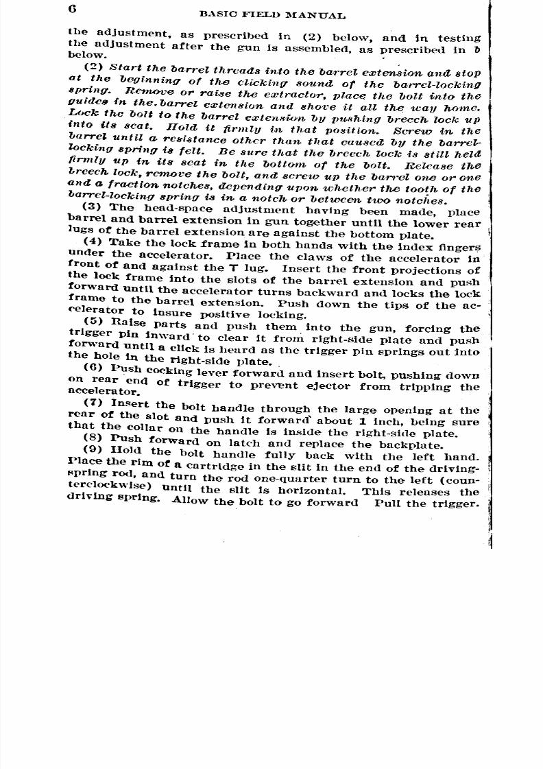
the adjustment, as prescribed in (2) below, and in testing
the adjustment after the gun is assembled, as prescribed in bbelow.
(2) Start the barrel threads into the barrel emtension ana stop
at the beginning of the clicking sound of the barrel-locking
spring. Remove or raise the emtractor, place the bolt into the
guides in the. barrel emtension and shove it all the way home.
Lock the bolt to the barrel emtenslon by pUllhing breech lock up
into its Beat. flola it firmly i,n that position. Screw in the
lJarrd until a rcwiJltance other than tlla,t causeeXby the barre~
locking 8pring i-8 felt. Be sure that the breech lock is stin heldfirmly up in its scat in the bottmn of the bolt. Release the
breech lock, remove the bolt, aneXscrew up the barrel one or one
and a fraction notcMs, depending upon whether the tooth of the
barrel-locking spring i-8 in a notch or between two notc;~es.
(3) The head-space adjustment having been made, place
barrel and barrel extension in gun together until the lower rear
lugs of the barrel extension are against the bottom plate.
(4) Take the lock frame in both hands with the index fingers
under the accelerator. Place the claws of the accelerator in
front of and against the T lug. Insert the front projections of
the lock frame into the slots of the barrel extension and push
forward until the accelerator turns backward and locks the lock
frame to the barrel extension. PUsh down the tips of the ac-('elerator to insure positive locking.
(5) Raise parts and push them into the gun, forcing the
trigger pin inward' to clear it from right-side plate and push
fonvard until a click Is heard as the trigger pin springs out intothe hole in the right-side plate •.
(6) Push Cocking lever forward and insert bolt, pushing down
on rear end of trigger to pre~nt ejector from tripping theaccelerator.
(7) Insert the bolt handle through the large opening at the
rear of the slot and push it forward' about 1 inch, being sure
that the collar on the handle Is inside the right-side plate.
(8) Push forward on latch and replace the backplate.
(9) Hold the bolt handle fully back with the left hand.
l>lace the rim of a cartridge in the slit in the end of the driving-
f'pring rod, and turn the rod one-quarter turn to the left (coun-
terclockwise) until the slit is horizontal. This releases the
driving spring. Allow the bolt to go forward Pull the trigger.

8/22/2019 Basic Field Manual Volume III-1932
http://slidepdf.com/reader/full/basic-field-manual-volume-iii-1932 14/203
BASIC }'IELl> l\IAXUAL 7
bJ Tests for correct a,djludmcnt.-A positive rule for head-
Rpace adjustment that will fit all cases can not be given, and
the following tests must always be ap11liedprior to firing the
gun:
(1) Work the bolt by hand two or three times, and in casethe breech does not lock smoothly, or the holt handle does not
go all the way forward, unscrew the barrel one notch.
(2) Raise the cover and the extractor. :\loYe the bolt
Slightly to the rear by means of the bolt handle. There must
be no rearward mOVCll1wntof the boltinde])(mdent of the barrel
Prior to 1ln.lockillg of the breech. If the bolt moves rearward
Independently of the barrel the adjustment needs tightening.C. Quick adjustment.-After the correctness of head-space
nUjustment for a particular gun and barrel has been established
by aetual firing, the proper notch for head-space adjustment
khould be marked und the munber of clicks required to screw
the barrel up tight in the barrel extension from this point with
the bolt removed should be counted. Then to adjust head space
qUickly, screw the barrel in until the proper number of fullturns has been made and stop with the barrel-loeking spring
In the marked notch, or screw the barrel tight into the barrel
extension. and then unscrew the required number of clicks.
12. Detailed disassembling of bolt (fig. 3).-a. Extractor.-
Turn extractor up and remove it to the left.
b. Driving-spring 'rod (fig. 4).-(1) Grcat care should be exer-
('ised in ,'cl11A(Yvinghe drivil1g-.'spring ,'od from the bolt as theforce of the driving spring '/,Chen'released can easily cause the
"od to slip away from the hand. If a person is strU('k lnJ the
"od very serious injury tnay result. To remove driving-spring
rod, place the protruding end of the rod on the table or a piece
(It wood. With the bolt firmly grasped by the right hand (palm
()f hand over the top of bolt), press down und at the same time
turn the bolt one-fourth turn to the left until the driving-spring
rod pin leaves its recess in the bolt. Slowly release pressure on
t he bolt, allowing it to l'ise under the action of the driving spring
Until about 3 inches of the rod protrudes. With the left hand
grasp the protruding portion of the rod and spring; raise the
holt from the table, at the same time keeping the rod and spring
In their same position relative to the holt. Separate the rod
/Iud spring from the bolt with a quick jerk. The quick, separat-
Ing jerk will not allow the spring to kink.

8/22/2019 Basic Field Manual Volume III-1932
http://slidepdf.com/reader/full/basic-field-manual-volume-iii-1932 15/203
8BASIC }"n:LD MANUAL
(2) Separate the driving-spring rod and the driving spring.
c. Cockillg-lct'cr IJ;n.-Withdraw to the left of the bolt.
d. Cocking let'er.-Llft out cocking lever.
e. Sear.-Helease firing vin b~ pushing down on sear. Hold
holt in left llanu, front end toward body, top up .. With pointof bullet placed near end of sear sllring push downward and to
the rI~ht to seat It in cut in lxllt. This releases the sear, whichwill drop out at the bottom of the bolt.
,. Scar 8[Jring.-(1) Turn the sear l'llring back to the left toclear the cut.
..,..&l;;:;:::=::.:......jj
-:~;;--&-=--I'IR1:G PINMWwy"'''!!I/IIttWollIWo.l~ SEAR~RIV/N(J .'JPR1N(J
. ro;;; =~Sl'AR",PRINGPIND1lfY1NG $PRI!(O ROO- - -SEAR 3PRINIJ
COCKING --'oc[([;a LEV~R PIN
FWt:RE 3.-llolt gronp
(2) Push "ith nose of bullet in hole in bottom of bolt to startthe sear.spring pIn up. To complete the removing of the sear
spring, place the tOl)end of the c()('king lever under sear springnnd pr~' down against the edge of bolt.
g, Pir;IIg 11;n.-Tilt the rear el\(l of bolt down and the firingpin will fall out.
13. Assembling bolt.-a. Place firing pin in bolt, striker
downward llnd to the front, and llush forward until the striker
projects through the small hole in the frollt of the bolt.
b. Uepla('e scar spring, by forcing sear-spring pin downward.
lly pushing wIth cartridge on top of pin, avoiding pressure Oil
sprIng propt'r.
c. lIold holt in left hand, front end toward the body, top up.""ith point of bUllet placed near end of spar spring push down-
ward and to the right to seat it in the cut in the holt. .
d. Push sear upward from the bottom, notched projection tothe front, and bold with first finger of left hand while prpssing
t '
~ ~
~

8/22/2019 Basic Field Manual Volume III-1932
http://slidepdf.com/reader/full/basic-field-manual-volume-iii-1932 16/203
BASIC FIELD l\1~~NUAL 9
downward and to the left on the sear spring with a bullet to
engage the end of the sear spring in the sear.
e. Heplace cocking lever, taking care that rounded nose onlower end is to the rear so that it ,vill properly engage rear of
l'ecess in firing pin.f. Insert cocking-lever pin from left side of bolt. Push upperenll of cocking lever to the rear before inserting pin, as the
holes are thus placed in alignment.g. Cock by pressing forward on cocking lever. Hold cocking
lever to rear and press down sear with bullet to release firingJlin and test correctness of assembly.
h. The same care should, be exercised in assembling thAJ driv-
ing-spring rod to the bolt as is exercise(l in 1'cmo'L'ing it . Place
driving spring on driving-spring rod. With the back end of the
rod resting on a table or a piece of wood, gather as much of the
spring on the rod as can be held compressed by the thumb and
fingers of the left hand. With the bolt securely held in theright hand, front end of bolt in palm of hand (fig. 4), slip the
holt over the end of the spring. Push downward to compress
Spring and allow driving-spring rod. pin to enter the slot in the
holt. Turn bolt slowly 90° clockwise until the slot in the rod
is crosswise to the slot in the bolt.-£. Insert the pin on the extractor in the rear of the two large
holes in the left side of the bolt, extractor pointing up. Turnextractor downward toward the front to engage the collar on
the extractor under the collar cut in the bolt.
14. Detailed disassembling of lock frame (fig. 5).-a. rush
out trigger pin from the left side of lock frame. Remove trigger
and trigger-pin spring.b. Push out the accelerator pin and remove the accelerator.
c. Hold lock ..frame with left hand, projections pointing up-ward, slot to the left, separator between second and third
fingers, first and second fingers gripping barrel-plunger spring.
With the thumb of the right band, press down and out on barrel
plunger to disengage plunger-guide pin from slot. Allow spring,
carrying plunger, to rise slowly. Lift out spring and remove
spring from barrel plunger.15. Assembling lock frame.-a. Assemble barrel-plunger
sIn'lng to barrel plunger. Hold lock frame with left hand, pro-
jections pointing upward, slot to left, lock-frame separator be-
tween seeollli UlHl tbird fingers. Seat end of barrel-plunger
98!l53°-32--2

8/22/2019 Basic Field Manual Volume III-1932
http://slidepdf.com/reader/full/basic-field-manual-volume-iii-1932 17/203
10B.\src FIELD MANUAL
FWl"RE 4.-:\lethod of all8l'llIbling and disassembling dl'lvIng sprIng,
dl.h'Iug-llprIllg rod, llnd bolt

8/22/2019 Basic Field Manual Volume III-1932
http://slidepdf.com/reader/full/basic-field-manual-volume-iii-1932 18/203
BASIC FIELD MANUAL 11
Spring in recess in lock-frame separator, barrel-plunger guide
Pin facing slot in lock frame, left. Hold spring with first and
second fingers of left hand. 'Vith thumb of right hand press
down on end of barrel plunger until barrel-plunger guide pin
cnn be seated in slot. Care should be taken that plunger under
action of spring does not slip out of hand.
0. Replace accelerator, tiPS up, rounded surface to the front.
InRert accelerator pin, taking care that both ends of pin are
fluf.lhwith the sides of the lock frame.
I
]
e:::=-- ~l ~-TRIGG£R
TIP"' it.:. (l e . O-lWIULPUlNtl<R
f}) . ~-ACClLERATOR PIN
. ACX1!.c.ERATOR ~_nARRI:r.PWN(j£R.3PRlN6
TRIGGER PIN
!/j-TRIGGER PIN .sPRING
FIGURE 5.-Lo(~k-frallle group
c. Pm5h front end of trigger up between separator and
SPllcer, placing the center in its square seating. Place spring
on trigger pin, small end of spring toward head of pin, and
1nfolertpin from the right so that spring is seated in the recess
provhled.16. Detailed disassembling of barrel extension (fig. 6).-a.
Pry Imlle't under front edge of the barrel-locking spring and
pun it out forward.b. Push out breech-lock pin and remove breech lock.
17. Assembling barrel extension.-a. Place breech lock in
Its slot, taking care that the double beveled surface is llP and
to the front. Insert breech-lock pin and insure that both endsof pin are flnsh with sides of barrel extension.
b. Insert barrel-locking spring in seating in left side of barrel
exten!'iion,hook inward, and force home as far as it will go.
~
~

8/22/2019 Basic Field Manual Volume III-1932
http://slidepdf.com/reader/full/basic-field-manual-volume-iii-1932 19/203
MeeCH l.OCK PIN
/=
R\SIC FIELD l\-IANUAL
I"IGl"RE 7.-Cover group
M;l:~r"u~rc;;:. Q
/JAR/II!l. l.hcXINO SPRINrJ
12
18. Detailed disassembling of cover.--a. Turn belt-feel
lever-pivot Spring outward and remove belt-feed lever pivot.
b. Draw belt-feed lever from belt-feed slide and remove slide
c. Insert nose of bUllet between cover-extractor spring nnnotch in cover-extrnctor cam. Pry out on spring to disengag(from cut.
19. Assembling cover.-a. Pluee forke(l end of cover-extrac-
tor spring under stud on Cover. Press downward with thumbon other end of spring, a t the same time PUshing toward stud,
and sea t projection of spring in notch of cover-extractor earn.
b. RPplace belt-feed slide in its grooves in cover,' taking care
that the Pllwl is pointing to the right as Cover goes on the gun.
c. Place front end of belt-feed lever in cut, stud on lever awayfrom COverand to the rear. Insert belt-feed lever-pivot spring
at rIght angles to cover so that lugs on pivot will pass through
cuts in cover. Turn spring inward toward base of rear sight
~

8/22/2019 Basic Field Manual Volume III-1932
http://slidepdf.com/reader/full/basic-field-manual-volume-iii-1932 20/203
BASIC FIELD l\IANUAL 13
Until lugs engage on underside of cover and spring locks in
place.
20. Disassembling of, parts dismounted only for repair.-a. Shock-absorbing group.-Unscrew adjusting screw and re-
Illove adjusting-screw plunger and spring. Remove buffer disks,
bUffer plug, buffer ring, and buffer plate through the rear end
of the grip. Replace in the reverse order.
b. Belt-holding pa.wl.-{1) Hold <lown the belt-holding pawl
and withdraw the belt-holding pawl split pin to the rear.
(2) Lift off the belt-holding pawl.
(3) Lift the belt-holding pawl Sl)ring from its seating.
(4) Replace in the reverse order.
c. Steam tube.- (1) Tbe steam tube need never be removed
Unless it becomes so clogged from the use of dirty water that
8tenm will not pass off, or the outer tube becomes stuck so it
Will not slide back and forth on the inner tube when the gun
lij held in the hands and tipped forward and backward. Great
care nlust be used to prevent danlage to the threads of the
81eam-tube front plug, and it should never be removed except
Under the supervision of an officer or by an experienced
Inechanic.
(2) Stand the gun with the muzzle up and water jacket
vertical. Remove the steam-tube front-plug screw. Place the
large screw-driver blade of the combination tool in the slit and
Unscrew the steam-tube front plug until the threads are dis.
E>ngagedand tbe steam tube can be lifted out.
(3) To replace, stand the gun exactly vertical, as prescribed
ill (2) above, and insert the steam tube. Gently screw in the
threads, stopping at once if there is any undue resistance. The
gUn flIld tube must be exactly vertical to insure that the conical
('lid of the tube enters its seating in the trunnion block. Forc-
ing the screw against resistance will damage the threads. If
It does not screw in easily, unscrew short distance, be sure
the water jacket is vertical, and try again until threads screw
In smoothly. Screw in tight without excessive force, and then
Position the notch in the rim of the plug exactly on the round
COuntersunk recess for the front-plug screw, unscrewing part
ot n turn if necessary. Replace the screw and screw it firmly
down into its countersunk sf'ating. If the notch in the rim isnot engaged by the screw head, the steam tube will not be aligned
in the front-end cap to permit lhe escape of steam and the
Wllter jacket will hurst from the steam generated in firing.
~

8/22/2019 Basic Field Manual Volume III-1932
http://slidepdf.com/reader/full/basic-field-manual-volume-iii-1932 21/203
14'BASIC FIELD MANUAL
21. Packing the barrel.-Asbestos packing is applied at the
muzzle and breech ends of the barrel to prevent leakage froIH
the water jacket. The amount of packing must not be excessive,
since the friction caused thereby will interfere with the actionof the mechanism. The proper amount can only be determined
by experience and trial. Usually a piece of packing about an
inch longer than the circumference of the water jacket is cor.
reet. It8hould be Well saturated with oil before being applied.
a. Pocking the breech. end.-Place packing in cannelure and
press home with screw driver and thumb. Wind it around,
pressing up against the wall of the cannelure. As the eml i~
crossed on the first turn, see that it is bound down flat. On
the last turn force the end under and see that it is bound down
fiat and worked well in. Insert breech enll of barrel into the
hole in the trunnion block and push forward gently, twistingbarrd until pa{'king is worked down to fit. .
b. Pack£nfl the. muzzle end.-Wlth the gun assembled, alloW'
the bolt to go forward or trip the accelerator so that the barrel
is fUlly forward. Remove the muzzle gland. Wind the pack-ing in even layers about the barrel with the first coil as close
as possible to the end cap. Push back the mUZzle or draw back
and hold the bolt, at the same time guiding the packing into its
seating. Screw in the muzzle gland and test friction of the
mechanism by pulling and releasing the bolt handle several
times. It there appears to be too much friction, remove one or
two coils of packing. The muzzle gland must be screwed upso that its shouhler is against the metal of the end cap and isJ:ot stoPpt'd by jamming against the packing.
22. Methods of changing parts.-a. Worn or bulged bar-
reIB.-The necessity of saving water In the water jacket dppends
('nUrely upon prevrliling conditions. In heat of battle, water
may not be obtained readily, Time also may be of the utmost
import:lnce. It it Is necessary to save the water in the water
ja('ket When chnn;,,"ing barrels, one of the following methodsshould be employed:
(lL First methfJd.-(a) Remove the bolt from the gUll.
(b) l'u!"h in on the trigger pin and pUll the lock frame to therear from one-fourth to one-half iu{'h,
(c) Remove the elevating pin and depress the muzzle ofthe gun. .
(d) Hold a plug at the mu.zzle of the barrel. (The steam.lllug cork wrapped in cleaning pat<'hes is suitable.)

8/22/2019 Basic Field Manual Volume III-1932
http://slidepdf.com/reader/full/basic-field-manual-volume-iii-1932 22/203
I
BASIC FIELD l\IANUAL 15
(e) 'Vithdraw the lock frame, barrel extension, and barrel
to the rear. As the barrel is withdrawn, follow it with the
}llu~or steam-plug cork and insert it in the hole in the end cap
Ill' Inuzzle gland through which barrel has been withdrawn.
(1) Place a plug or twisted patch in the muzzle of the new
barrel.(0) Connect the barrel with the barrel extension, being care-
fUl to secure the proper head-space adjustment.
(h) Replace the groups in the gun. When the muzzle of the
1l1'W barrel passes through the hole in the end cap, remoye both
th(~plug and steam-plug cork. Hun a patch through the barrel.
(i) Care must be exercised in removing and assembling the
1181'1'eln order not to disarrange the packing. Very frequently
III assembling the new barrel the front packing is carried (Jut
hy the lfluzzle.(2) SCC01Hl method.-Drain the water from the water jacket
Into the water box. As the water jacket has to be refilled after
the new barrel is seated, this method will require more time, than the method described above.
b. Changingparts.-If it is imperative that fire be maintained
. (Ir Immf'diately resumpd, a broken minor part should be re-
I'lnepclby substituting the complete spare part which contains
it. Thus a broken firing pin woul(l be remedied by changing
holts; a brokpn ejector by changing extractors. Later, as oppor-
tunity permits, the small parts will be repaired or replaced inol'(ler to make the larger part again available for use. In case
tIl(~('omplete bolt has beeR.changed, a check should be made of
the head-space adjustment.
SJ<:,CTIO:-' III
CARE AND CLEANING OF GUN, BARREL, AND TRIPOD
23. General care.-It is essential that the gun be maintainedIII the best mechanic-a1 condition at all times. It must always
lie kept clean and covered with a light coating of oil. particular
Ilttentlon must be paid to the bore. Care and cleaning will not
ll(~confined to the gun alone but will include the tripod and all
IH'ecs8oricS. Belts and ammunition must be kept clean and dry.
24. Points to be observed before, during, and after firing.-
'rhe following table of points to he observed before, during, andUfter firing will be found convenient as a guide for the properI .Or. of the gun. ItwlJ l also serve as a gniJe for in"" ••Uon.
~

8/22/2019 Basic Field Manual Volume III-1932
http://slidepdf.com/reader/full/basic-field-manual-volume-iii-1932 23/203
16BASIC FIELD MANUAL
!
,I
,I
I
I
I
I...2S<IIt::
I
I
I
I
!t:
I
I
I
i
I
I I I
I •
I -o:i !i
: ~ !.I
E ] .~~ ~
~ ~ ~ ~

8/22/2019 Basic Field Manual Volume III-1932
http://slidepdf.com/reader/full/basic-field-manual-volume-iii-1932 24/203
!
f
BASIC FIELD l\IAXUAL 17
25. Care in cold weather.-a. Thin the lubricant on the work-
in~ parts with kerosene or gasonne until gun is warmed by
tiring.b. See that water at the gun does not freezt~.
o. Test the gun fn~quently to S('e that it functions properly.
26. Care during a gas attack.-a. Close lids of ammunition
hO)(Nl. .
11. Guns should be eIpaned as soon as possible after a gas
attack.
c. Oiling will prevent corrosion for about 12 hours.(1. Clean all parts in boiling watpr containing a little soda,
if available.
c. All traces of gas must be removed from ammunition with
11. ""lightly oiled rag; then thoroughly dry the ammunition.
f. Cosmoline resists gas corrosion more than lighter oil. ILl
lllally ('Xllo:-;urps,esppcially of long duration, ammunition treat-
(\11with sperm-oil evidences more severe corrosion than un-
r1ro/('cted cartrillges.
27. Care and cleaning of gun and tripod.-(A more de-
taiIe<l discussion of this subjed ('an be found in TR 1395-A.)
a. 7'he b01'c.-DisasHemble tlw groups from the gun. The barrel
"'ilh the barrel extension attaehpd is placell, muzzle down, in
;a V'NIHel containing hot water and issue soap, a sal soda solution,
or, laeking' theHe, hot watl.'r alone. (It is mo~t ('onn'nient to
('!I'Un the bore immediately after firing, as hot water is avail-
llbl{~n the water jaeket.) Use the cleaning rod with flannel
rllllf('h to pump water baek and forth through the bore for about
I()nl~minute. 'l'horonghly dry and clean the bore before applying
lit (:outing of lubrieating oil.
. 11• Afoviufl 1/ort8.-'1'he moving parts should be kc>ptclean and
}IIIJrleatPllhef()I'{~,during,. al1l1 after firing'. Avoid pulling a
I Jilt/'tlyempty helt throu~h the feell olwlling, as the lint and dirtI thllM ('ollpefell intprfc>re with the fundioning of the feed
1111'I'lr:llliHnl.
0. 71he tripod.-Keep nil threads lightly oiled. Avoid exces-
f\lv(~ oil from g'ptting into the spI'l'ations, ns dirt and ~llnd will
~;:JII(>ctherpln aIld int('rf('l'e with ]JoHitive hleking of the lpgs.
IhI' }Iintle should he 1'('mon'll oecllsiollally, deanI'll, nd lightly
°il",l \\'}\('re tlwl'e is frktion with the sll<'kpt. Oil should not be
i 111111'('11n the :-;I'atingof till' traversing llial, as it will cause dirt
to ('ollect awl interfere with easy dial ndjustment.
~
8.
8/22/2019 Basic Field Manual Volume III-1932
http://slidepdf.com/reader/full/basic-field-manual-volume-iii-1932 25/203
18 BASIC FU:LD MANUAL
SECTION IV
IMMEDIATE ACTION
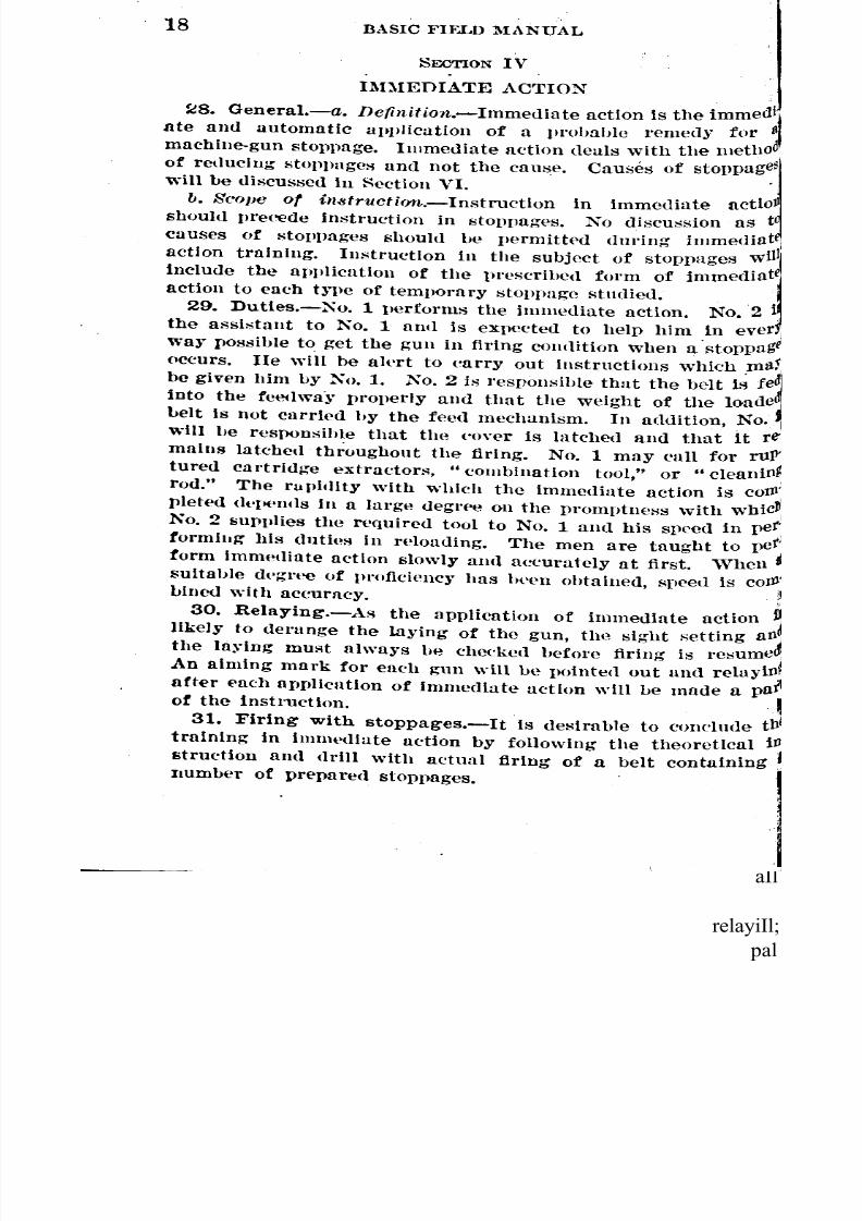
~8. General.-a. Dc(inition.-Immediate action is the
ate amI automatic aplllication of a llrohuhle remedy for )
machine-gun stoppage. Immediate action deals with the llIetllO
of redUcing stoppages and not the cause. Causes ofwill be discussed ill Hection VI. .
b. Scope of insfruction,-Instmction in immediate actloJ
shoUld pre('ede instruction in stoppages. No discussion as t
causes of stoPl)ages shoUld be permitted dming irnmediat:
action training. Instruction in the subject of stoppages Will,
include the allI)lication of the prescrihed fOl'm of
action to each t)"pe of temvorary stoppage stndied. ,
29. Duties.-Xo. 1 performs the imnwdiate action. No.2 i
the assistant to No. 1 and is expected to help him .in ever
wa)" possible to get the gun in firing cowlition when a stoppage
(lccurs. lIe will be al(\rt to earry out instructions which ,lIla5;
be given him by No. 1. No.2 is reslwnsible that the belt IS,into the feeclwa'~"properly and that the weight of the loa de
belt is not carried hy the feed mechanism, In addition, No.
will he responsihle that the ('over is latched and t.hat it
maius latched throughout the firing. No.1 may call for ru~
tured cartridge extractors, .. combination tOOl," or "cleaniOrj
rod." The rapIdity with which the immediate action is
plete<1(]('II('ntlsill a large degl'ee on the promptness withNo.2 supplies the required tool to NO.1 and his speed in
tormiIlg bis duties in reloading. The men are taught to
form immetliate action slowly and a(~curately at first. 'Vhen
suitable dt'~ree of proficiency has bt\en obtained, speed isLlnetl with accuracy. :
30. Relaying.-As the application of immediate action
likely to derange the laying of the gun, th(~ sight I';ettingthe laJing must always he cheeked before firing is resume
An aiming mark for each gun will be pointe(l out and
after eacb application of immediate action will be made aof the instruction. . ,
31. Firing with stoppages.-It Is desirable to conclude tIll"
training in imnll'diate action by following the theoretical il
struction and drill with actual firing of a belt containingIlUmber of prepared stoppages.
immed~
'
stoppage~
immediate]
fe
re
coJJ
WbiC pet'
pet
CO
aIl
relayiIl;
pal

8/22/2019 Basic Field Manual Volume III-1932
http://slidepdf.com/reader/full/basic-field-manual-volume-iii-1932 26/203
r
i
I
I
BASIC FIELD l\IAXUAL , 19
32. Phases of immediate action.-'Vhen a stoppage occurs
ill firing, the gunner will be taught that the set of actions pre-
~erioed helow, or such part of them as is necessary to reduce
the stoppage, will be performed in the sequence, first phase,
8f'Condphase, third phase. He is trained to follow habitually
thl8 proce(Iure without any attempt to analyze the cause of thetl'OUble.
a. Pi"l!;t pllasc.-Gun -fails to fire.
(1) Pull holt handle to the rear and release it. (If bolt
handle fails to go forward, go to spcond llhase immediately,)
(2) Helay and fire.
b. Second Vha8c.-GUll still fails to fire.
(1) Uai:.;e the cover. (No, 2 removes the helt and the first
l'Ollndfrom the belt. No.2 holds this round until firing is re-
~Ulnedor until No.1 calls for it.) Place the left hand under
the receiver, pull bolt handle to the rear, raise the extractor,
IInd glance into the reeeiver.
(a) If a round remains in the chamlJer, call "Cleaning rod"to No.2, who removes the roun(I with the cleaning rod.
(1) If a round sticks in the T slot, call" Combination tool"
to No.2 and remove the roulHl with the combination tooL
(c) If a round is ('jected, examine it. If the round shows the
l'!ng mark of a sepnrat('d cnse, call .. Ruptured cartridge ex-
h'Qctor" to No.2, and remove the separated Cllse.
(d) If there is no rou11lIin the chamber or T slot, and none:Ii ejected, call "}~irst round" to No.2 and examine it. If it
Ii a short round and shows a nick Oll the rim, replace the belt-teed lever.
(2) Heload, reIny, and fire.
C. Third phase.-Gun still fails to fire.
(1) Place the left hand under the reeeiver, pull bolt handle
to the rear, and hold it.1 (a) If a cartridge is ejected, call" Bolt" to No.2 nnd change)(1]t8.
t (b) If there is no ejection, examine the fe<'IImechanism (ex-
I'actor, belt-holding pawl, and ('over), ancl replace defective
I
lllltt
(2) Reload, relay, and fire.
33. Usbg the ruptured cartridge extractor.--a. There aret\\'o forms of ruptun'fl ('urtridge extraetors. One is similar in
I f01'1I} to 11 cartridge. TI}(~M1\:.IV is of the same general form,
\"lth the addition of 11 lever handle.
I......
~

8/22/2019 Basic Field Manual Volume III-1932
http://slidepdf.com/reader/full/basic-field-manual-volume-iii-1932 27/203
20 IUSIC nELD MANUAL .
b. To use the cartridge form, place it in the ffled way against
the cartriuge stops al1(l engage tl,le rim with the extractor OJl
the bolt. IIolu down the extractor with the fingers of the left
hand and draw the boIl to tlw renr. Allow the holt to go for'
waru slowly, guiding the ruptureu cartridge extractor downT slot to insure its entering the chamber smoothly. Allo,:
bolt to go fully forward, Wit,hdr:lW it slightly and let Itforward again. Strike forward on the holt handle with the
palm of the right hanu to insure seating of the ruptured car'
tridge extractor in the Sf'Illll'ated case. Place left hanu undet,
receiver anll pull the holt handle to the rear, catching the
ru[ltured cartridge extractor as it falls out. In usingruptured eartrhlge extractor, do not let the bolt handle fly for'
ward from the rear, as 11heshoulder on the ruvtured eartridg:,
extractor is likely to strike the edge of the chamber and make
hurl' on it, Which will prevent the full entry of a cartridge un J ,'
renll(>r the barr('l useless. '.
o. To use the l\Ik. IV, draw the bolt handle to the rear
"hang the bolt" by engaging the extractor-earn plungpr innotch in the rear of the extractor-feed earn. Insert the nose 0:the ruptured cartridge extractor in the chamber, handle
pU!o'hforwaru 11>l*'ut firmly in the separated case, and PUl~,Ib:l('kward on the handl<>.
d. Separated Cll!o'eS should be r('moved fWIll the rupture
cartrluge extractor so thll t it will again be rpady for use.
do this, the end of the rupturl'd eartridge extractor must bjunscrewl'd, the separated case taken off, Hnd the end screweon again.
34. Removing a round from the T slot.-a. IIolu back
holt and raise the extractor with the first finger of the rigb
hund. The round will usually fall out unless it has a thickor the T slot is defective.
b. If the round will not fall out When the extractor isUse the" combination tool." If the round is not below the
handle slot, insert the scre.w-drlver end of the combination toO,
through the slot under the rear end of the cartriuge and pr,
round up and out of the T slot, holding down the front end 01,
the cartridge with the finger.
o. If round is too far down the T slot for the insertion of tb]
combination tool, "knock it down." IIolu the holt handle tthe n'ar with the extractor raised. Place the screw-driver eI1
tilethe
g
the
un(
th
uP'
'1'0
tIl
riJ
r&ised b01t

8/22/2019 Basic Field Manual Volume III-1932
http://slidepdf.com/reader/full/basic-field-manual-volume-iii-1932 28/203
f
I
I
BASIC FIELD :MANUAL 21
through the top of the receiver into the top of the cannelure of
the cartridge and drive the round downward out of the T slot
hy striking the upper end of the combination tool with the palm
ot the hand.
35. Removing a case from the chamber.-If there is an
empty case with broken rim stuck in the chamber, call" cleaning
rC;d." Remove round from the T slot if there is one. Hold back
holt. Insert the deaning rocI from the muzzle and knock the
empty case from the chamber. Be sure the cflse does not stick
In the T slot. If several rounds stick in the chamber in close
SUccession,squirt sOllieoil on the ('hamber brush and thorougnlyElcruhthe chamber.
36. Test in immediate action.-a. Preparation.-The test
Iii prepart'd as follows: Four guns are set on a line with 3-pace
1IIter\'als. On each gun a different stoppage is prepared, the
reeei\'er covered with a cloth, ancI the firing pin released. At
l(!ast two of the guns will be prepared with stoppages which will
l'l'quire the execution of the second phase of immediate action.Identical targets are placed in front of each gun. The aiming
lllark for each gun is sueh that one uesignation applies to all
Of them; for example, "The aiming mark for each gun is to be
the black paster in the center of the target in front of each
RUn." After the stoppage has been prepared, the gunts so laid
that a slight manipulation of the traversing and elevating gears
Jlt llecessary in order to lay accurately on the aiming mark.'l'he sight setting on all the guns is the same. .
1). Procedure.-The man to be tested is called up and given
the aiming mark for each gun and the sight setting to be used.
lIe then takes the proper position at the gun. As the instructor
r('ll1oves the cloth from the receiver he announces "Gun fails
to fire," and the man undergoing the test immediately applies
the llecessary immediate _action. As soon as he has performedthe correct action at this gun, he presses the trigger, and then
the Instructor orders Next gun. The man moves as quickly
Us IlOssible to the gun next In order. Here he takes the correct
1l0lilitionwithout command and, as soon as the cloth is removed
(1'0111he receiver, applies the correct Immediate action. The
11l'ocedureat the remaining guns Is the same as at the second
gUll. As he presses the trigger of the last gun, the instructor
Iat the gun calls" Time," indicating that the man has completed
the test.
I ]2~~OO

8/22/2019 Basic Field Manual Volume III-1932
http://slidepdf.com/reader/full/basic-field-manual-volume-iii-1932 29/203
BASIC FIELD :MANUAL22
c. Additional rules for test in immediate action.-(l)
guns are placed out of sIght and not in effective hearingtance of the men waiting to be tested.
(2) An offic-erOr noncommIssIoned officer is at each gun toconduct the test at that gun as well as to grade the man
(3) It, after apparently corr'ecting a stoppage and pressin(
the trigger, the instructor should say, "The gun still fails to
fire," the man taking the test then applies the next phase ofimmediate action.
(4) The officer ~r noncommissioned officer conducting the test
at <'Rchguo, or a mao detailed, performs the doUes of No.for the man undergoing the test.
d. Time allOlccd.-Two minutes. Time is taken from
instant when" G.un fails to fire" is called at the first gun untilthe instructor calls" Time" at the last gun.
c. Pcrformance._(1) The correct immediate action forstoIlpage is applied. .
(2) The gun is loaded.(3) The gun is laid.
(4) The trigger is pressed.
SF..cTION V
MECHANICAL FUNCTIONING
37. Trigger action: (fig. 8).-The trigger being pivoted, a pull
on the r('ar ('nd lowers the front end.. The trigger cams force
the sear down against the action of the sear spring. The searl
notch Is released from the shoulder of the firing pin. The firing'r
pin spring forces the firing pin forward to strike the primer. .
38. Backward movement of the recoiling parts (figs. 8
and 9) .-The explosion forces the recoiling parts (barrel, barrel
extension, and bolt) backward, locked together, about five-
('ighths Inch. During this movement the breech lock Is forced
down by the front projections of the iock frame acting on the
breeeh-Ioek pin. This unlocks the bolt from the barrel exten'
sion and permits the bolt to continue to the rear. As the barrel
l'xtension comes to the rear, the "barrel plunger spring is cow'
pre~s('<1and the rear end of the barrel extension strikes theaccelerator and turns It backward.
39. Backward action of the accelerator (fig. 8).-As the
accelerator turn~ baekward it strikes the bottom projections oIl
the lJOlt and accelerates Its movement to the rear. The clawS
~l
Tbe
diS
tested:
the
eacb

8/22/2019 Basic Field Manual Volume III-1932
http://slidepdf.com/reader/full/basic-field-manual-volume-iii-1932 30/203
• BASIC FIELD l\IANUAL 23
Of the accelerator engage the shoulder of the T lug, locking the
harrel extension to the lock irame. . I
40. Backward movement of the bolt (figs. 8 and 13).-As
the bOltmoves backward the driving spring is compressed. The
bOlt brings with it a cartridge from the belt gripped by the
eJrtractor and an empty case from the chamber gripped in the
"r slot. 'l'!le extractor-cam plunger 'rides along the top of the
COCKINS LEvell,
JJACKPLATE.
~Ti .RCL EJlT£NJION
JjARR L EXTENSION
FIGURIIl9.-llnrrd, bolt, locJc frame. and barrel extension in
, firing position
'eJrtrnctor cam and extractor-feed cam until it is forced in by
the l,eveled pnrt of the extractor-feed cam. The extractor is
then forced down by the cover-ex'tractor cam and the plunger
~Dringsout behind the extractor-feed earn.
'41. First act of feeding (figs. 10, 14, and 15).-As the bolt
lilovefi!backward and the stud on the belt-feed lever moves to
:he right in the earn groove it forces the belt-feed slide to theeft. The belt-feed pawl engages on the left of the first car-
tridge, Which is held in position by the belt-holding pawl.
42. Cocking action (fig. 11) .-As the bolt moves backward,
~he uvver pnd of the cocking lever is forced forward, which

8/22/2019 Basic Field Manual Volume III-1932
http://slidepdf.com/reader/full/basic-field-manual-volume-iii-1932 31/203
24 BASIC FU',LD :MANUAL •
brings the lower end to the renr. The lower end brings with it
the firing pin, thus compressing the firing-pin spring. The
shoulder of the firing pin engages the notch in the sear, which
is pulled upward by the ad ion of the sear spring, the triggel'cams now being disengaged from the sear.
43. Action of the driving spring (fig. 12).-:-When the rear
of the bolt strik<'S the buffer plate its remaining force is all-
sorbe(l in the fiher disks and in friction when the brass buffer
ring is forced over the buffer plug and expnnds ngainst the
inner wall of the grip. The driving spring then forces the bolt
forward.
IJZL1'
MLTHOlDINQ
MWL AND "'PRING
NLT '~I!D Ll!VI!R PIVOT/lND .3PR//'I6
FIGURE }O.-Helt feed mechanism
44. Forward movement of the bolt (fig. 13).-When the bolt
starts forward, the extra dol' is guided downward hy the actiOll
of the extrlldor-feed earn on the extractor-earn plunger. Thiil
causes the extractor to foree the cartrhlge down the T slot ill
line with the chamher. The ej(~ctor knocks the empty ease frolll
the T slot and holds the cartridge in line with the chamber.
The upper end of the c()('king lever is forced backward and the
lever end moves forwanl away from the rear of the firing pill.
45. Rele:lse of the recoiling parts (fig. 12) .-As the bolt
goes forward its bottom projections strike the accelerator and
turn it forwar<1. This ulllot'lUI the barrel extension from the
lock frame. When the accelerator has been tripped the barrel
extension and the barrel move forward, assisted by the barrel'[
plunger spring. Part of the forward force of the bolt aetil
through tho .,,'elorlltor to I'URhthe hlirrel ex'elislon forw.r~'

8/22/2019 Basic Field Manual Volume III-1932
http://slidepdf.com/reader/full/basic-field-manual-volume-iii-1932 32/203
BASIC FIELD l\fANUAL 25
46. Loading and locking action (figs. 12 and 13).-As the
holt goes forward the extraetor rises as the plunger moves
fORWARD PO.5ITlON
BACfMARD POSITION
FIGUREn.-Firing mechanism
Illong the top of the extractor cam and the ejector moves out-
'vard, leaving the cartridge in the chamber gripped by the T
fllot. The extractor grips the first round in the belt and Is held
down firmly, ready to extract it, by the cover-extractor spring.
DRIYlNO 3MfN(J
ROD
TP/(}(JJ!R
FIGURE12.~R.e~ation of parts in backward position
~he hrpceh lock is forced upward by the breech-lock earn and
locks the breech just before the recoiling _parts reach the firing
1>osition. The breech lock engages in a recess cut in the bottom
of the bolt and thus locks it firmly to the barrel extension and
Ilgainst the rear end of the barrel.98953-32--3

8/22/2019 Basic Field Manual Volume III-1932
http://slidepdf.com/reader/full/basic-field-manual-volume-iii-1932 33/203
'2GBASIC FIELD MANUAL
'OPER EXTRACTOR ~PRIN~
EXTRACTOR CA!1
FIGURE 13.-Extractlng nnll loadIng mechanism
< '~~,jLJDt!,
l'IGt:RE H.-Cover and shock-ubRorbinggroups
rXT1IACTOR CA!'I PUIN(JCA
FIGURE 15.-Barrel extensIon, bolt, ,and lock~frame group

8/22/2019 Basic Field Manual Volume III-1932
http://slidepdf.com/reader/full/basic-field-manual-volume-iii-1932 34/203
BASIC FIELD l\IAXUAL 27
47. Section action of feeding (fig. 10).-As the bolt goes
forWard the stud on the belt-feed lever moves to the left in the
caUl groove and forces the slide to the right. The belt-feed
IJuwlcarries tlJe first cartridge to the right against the cartridge
foltops,eady to be gripped by the extractor. The next cartridgei~ ('anied over the belt-holding pawl, which rises behind it and
holds it in position to ue engaged by the belt-feed pawl on its
llext movement to the left.
48. Trigger action in automatic fire (figs. 8 and 12).-If
the trigger is held, as the sear moves forward with the bolt,
the trigger cams engage the sear cams and force down the sear,
releasing the firing pin. 'l'lle gun thus fires automatically, re-ll('ating the operations of functioning already described.
SEJCTIO:f VI
STOPPAGES
49. General.-'Vhile immediate action and stoppagt's are
elosply related, the former is treated separately to emphasize
tIle advisability of teaching immediate action as an automaticIlTid distinctive operation without consideration of causes.
h'over care of the gun and attention to the points before, dur-
ing, nnd after firing will greatly reduce the liability to stoppages,
llurticularly if the gunnpr has an intelligent understanding of
the reasons why stoppagps generally occur. Prcrcntion is the
1,c,~t 1'Cl11Cdy for all stoppages.
50. Classes.-Stoppages may be dassell under two mainhl'udings :'
a. 1'cmporary.-Temporary stoppages are caused by-
(1) Failure of some part of the gun of which a duplicate is
earried.
(2.) Faulty ammunition,
(3) Npglect of points before or during firing.
(4) Lack of knowledge of the operation and functioning ofthe gUll.
b. ]'l'olol1gC(Z.-Pl'olonged stollr:nges are causeu by a failure of
folOll1eart that, 3S a rule, ('an not he remedied by the gun squad
U!Hlerfire or without skilled nssistanefl. These nel'essarily put
the gnn ont of netion for a more or less prolonged pericH!.
51. Ullusual malfullctiolls.-a. Rccllrrin!! short 1'ound.'l.-
COl'l"l'CtiOllf this malfullction is IJl'ovideu for in immediate ae-

8/22/2019 Basic Field Manual Volume III-1932
http://slidepdf.com/reader/full/basic-field-manual-volume-iii-1932 35/203
28 BASIC FIELD MANUAL
tion. In guns In which the parts are badly worn It oecur'l
frequently. Excessive wear of the belt-feed lever 5tud,
feed lever pivot, and front end of the belt-feed lever, or a bent
belt-feed lever, allows lost motion In the action of the belt-feed
lever so that the slide does not force the cartridge fully to theright against the cartridge stops. This permits the left corner
of the extraetor to strike the rim of the cartridge when the
bolt moves forwal'd. The extractor fails to engage the cannelure
of the eartridge and drives the case forwlIrd over the lmllet,making a short round.
(1) Examination of the base of the first cartridge removed
from the belt in immediate action wiII show a dent in the rearend of the ('ase, made by the corner of the extractor. The bullet
Is driven part way into the brass case.
(2) As a temporary remedy, remove the cover-extractor
spring. This will usually allow the extractor to ride up over
and engage the cartridge, At the first opportunity replace tbe
cover-extractor spring and put in a new belt-feed lever andbelt-feed lever pIvot,
(3) The belt feed is correct when the slide protrudes about
one-sixteenth inch beyond the right edge of the cover. If the
edge of the slide is flush with the right edge of the cover, the
gun may function without short 1'0. uuds, but the cartridge is not 1.
against the cartridge stops uule:o;sthe slide protrUdes.
(4) A defective belt-feed lever may be straightened to make it
l,ush the slide fUlly to the right. I'lace it in a vise and carefully
fH}UeeZet to reduce the amount it is bowed or plnce it on edge
with the two ends resting on a hard surface and tap the middle
with a light hammer until the same result is obtained.
(5) The left corner of the extractor may be flIed down by au
experienced mechanIc in Such a ,manner that the extractor will
he cammed over the buse of the cartridge instead of striking it.
b. Dc!cctitVJ triguer.-(l) I!'orward end of trigger sprung'
downward; trigger too short, or beveletl surfaces of trigger and
!'ear burred or worn. ({{nnaway gun.) The gun cun not be
('ontrolled through the trigger. it will fire the moment the bolt
Is home the second time during loading, or, if the defect occurs
during firing, the gun will not stop firing when the trigger br£.le,ased.
(2) To remed.r-
(a) Ket:,p the gnn direcf{\d 011 the target.
belt.

8/22/2019 Basic Field Manual Volume III-1932
http://slidepdf.com/reader/full/basic-field-manual-volume-iii-1932 36/203
I
i
r
I
BASIC FIELD MANUAL 29
(b) Raise the cover and remove the belt. Raising the cover
fltoDf>he firing.
(c) Strip lock frame from the gun.
(d) Examine the trigger and sear and remedy the defect.
c. Broken barrel ea:ten.~~i()JL.-(l) 'l'he bolt will not go homenlld the gun will stop firing". In rare cases the gun will fire a
fl'\V rounds with a brokt'n burrel extension.
(2) To remedy-
(a) When performing immediate action the breakage will be
Ob\"ious.
(r) Strip the groups from the gun and replace broken part.
d. Brolcen T slot.- (1) A broken T slot will fail to extractthe empty case from the ehamber and will usually scar the rim
Of the case.
(2) When glancing into the chamher in the second phase of
hillnediate action, the broken T slot may be seen; or, when
the empty case. is removed with the cleaning rod, the rim will
l(lSllalIy give an indication of the broken part.
e. Loose bullcts.-In some lots of ammunition which have
""Nl in storage for a long time, there is a certain percentage'If ('artridges in which the front end of the case does not hold
th~ bUllet firmly. 'l'he end of the case is usually split where it
gr'iJ)sthe bullet. Such eartridges usuall~' load satisfactorily in
the belt-tilling machine alHI are not noticed. 'Vhen the ex-
fl'uetor withdraws the cartridge from the belt, the case only is
"'ithdrawn, the bullet rpmaining in the lJelt.
(1) Examination of the mechanism of the gun will disclose
'gl'Uins of 100Hepowder in the mechanism and chamber. This
]IOWderusually In'events functioning" of the parts and must be
1'('lllO\"p(}ith the ehamher brush before firing can be resumed.
If the gun is very hot, the powder may fiash and burn the face
,(II' hands of the gunner as he raises the cover.
(2) '1'11ere is no way to prevent this stoppage eXc0pt by
;'J{uminatton of suslwC'ted ammunition, round by round, either
llefore or after it is IOlHl0din the belts. The cartridges should
Ie held and an effort made to pull eaeh bullet from the case
,With the fingers. As this stoppage probahly takes longer to
('leur than any other cHusell by faulty ammunition, and as it
(I('('urs frequently in SOllie lots of ammunition, the importanee
Of eXamina tion of ammunition will be apparent.
~

8/22/2019 Basic Field Manual Volume III-1932
http://slidepdf.com/reader/full/basic-field-manual-volume-iii-1932 37/203
30 BASIC FIELD MANUAL
f. Tight packing.-Too-tlght asbestos packing will give slug'
gish operation and stoppages. MUZZlepacking is more likely to
cause trouble than breech packing. .
52. Classified table of stoppages.-A classified table of usual
stoppages is found. below.' The column headed "Method of
preparation for instmction in immediate action antI stoppag(~s#
should be used for reference only. Throughout instruction ill
usual stoppages the prpscrihed form of immediate action: should
be applied in sequence until the stoppage is -remedied. It will
be impressed upon all thllt the position of the bolt handle is not
to be taken as an indication of the phase of imme(liate actioP
to be applied to remedy a stoppage. This table will serve as II
guide to instruction in the usual stop £luges.
Phase or im-mediate action Stoppage.'l
Method or preparation ror in'struction in immediate actiaDand stoppages
1. Place a dummy cartridge 10,the belt. r
2. Leave an empty loop in tbe,belt.
3. Do not prepare.l4. Drive the front portion or'
cartridge securely on ,dummy cartridge. Pull thebolt to the rear and pl!\()llthe cartridge properly ov!race of the bolt. Ease thet
bolt forward. ,1. Pull a cartridge partlaily
of the belt.2. Place a short round in the belt.~. Insert the front end of a sepa'
rated case in the chamber,and loud. For range put'poses file a line around tbecartridge case about Y2 incblfrom the baso. Be carefUnot to file too far through, asthere is danger of the bullel
staying in the charnbflr.4. Do Dot prepare.1
.~. Insert bulged round in thebelt.
6. no lIot prepare"7. Do not prell:lre"
4. Separated cases due to toomuch head space.!
5. Bulged round.
6. Til:ht loop in tht1 helt.17. Bullet loose in tho cartrid~e
case.!8. Battered or thick rim or
cartridge.
9. Broken canllelure.
8. Place It hattered or a thick'rimmed oortridge in tbebelt.
O. Place a dummy cartridJote
with rim filed on: in tbechamber.
10. Set-back primer.! 10. Do not prepare. I
I Not prepared ror instruction in Iu;.mediate action.
First phase 1. Misfire due to defectiveprimer.
2. Empty loop in belt.
3. Stretched or torn helLI4. Separated case which is re-
moved from the chamber hythe new round when thebolt is pulled to the rear.
Second phase._ 1. Delt improperly loaded.
2. Short round.
3. se8~:~h~~~:-'~~~ht~:b~1ris pulled to the rear.
OUI

8/22/2019 Basic Field Manual Volume III-1932
http://slidepdf.com/reader/full/basic-field-manual-volume-iii-1932 38/203
-BASIC FIELD MANUAL 31
Phase ofim-lllediate action
StoppagesMethod of preparation for in-struction in immediate actionand stoppages
------1--------------1-------------Second phase... 11. Thin rim. permitting the• nose of the bullet to dropbelow the chamber.!
.ThIrd phase 1. Short or broken firing pin.
2. Weak or broken firing pin-spring.-
3. Faulty engagement of tiringpin and sear notch.
4. Broken sear !'lpring.5. Delt-foed lever pivot out,
worn, or broken.6. Bont or worn belt-feed lever.7. Belt-feed pawl spring out or
woak.8. Delt-feeti pllwl pin out or
partially out.9. Cover-extractor spring out or
weak.
10. Belt-feed lever weak (stud onlever jumps out of earngroove).
11. Damaged extractor.12. Delt-holding pawl out or
spring weak (will cause ro-curring flrst phas!').
13. Broken extractor or ejector.
14. BrokAn or damaged T slot,!
11. Do not prepare.!
1. As,~emble the bolt with adefective tiring pin, or place5 or 6 successive range-. dummy cartridges in thebelt, for instruction in im.mediate action.
2. Same as 1.
3. Assemble the bolt with de-fective parts.
.1. Same as 3.5. Assemble the cover with de-
fective part.fl. Same as 5.7. Remove belt-feed pawl spring.
8. Remove belt-feed pawl pin.
9. Remove cover-extractor spring.
10. Assemble with defectivepart.
11. Same as 10.12. Remove belt-holding pawl.
13. Assemble bolt with defec-tive part.
14. Do not prepaTe.l
------------_ .._-------------------------'-------------
INot prepared for instruction in immediate action.
SJ <X:'!10N YII
TRIPOD MOUNTINGS
53. General.-The weight of the machine gun makeR neces.
~ary the use of some form of fixed mount to support the gun in
firing. 'rhis mount is usually equipped with mechanical devices
by llleans of which the fire of the gun can be suitably controlledIndirection and elevation. In the United States Army the fixed
mount takes the form of u tripod, with the gun carried on a
cradle 80 arranged that it may be rotated about a pivot, per-
lnitting fire in any direction without moving the mount itself.
Changes in elevation are obtained by means of u hand wheel
"'hleh controls a screw attllchc>d to a bracket on the bottom
lllate of the gun near the rear of the receiver. The legs of thetripod are so constructed that they may be mounted at various

8/22/2019 Basic Field Manual Volume III-1932
http://slidepdf.com/reader/full/basic-field-manual-volume-iii-1932 39/203
32 BASIC FIELD MANUAL
heights independentl~' of each other, thus permitting a level
mounting of the gun on sloping amI uneven ground. Three
forms of tripod exist at the present time, the Drowning machine
~un tripod, 1\11917,the mnchine-f.,'Untripod, M1918, and the Mk.IV. The 1\11917 has certain advantagps over. the other tw
types, and will be the one normally issued to troops for use ill
Ileace-t1me training. The Ml918 and Mk. IV are kept in storag
as a war reserve.
7'VN.JJLUI CLAMPING HANDLI!
PIIVTLE
FIGURE 10.-1'11IH7 tripod
54. Description, M1917 tripod (fig. IG).-a. The centrll
member of the tripod consists of the brass socket with thrc
projecting lugs. Serrated front cluteh plates are attached t
the front Jugs. The front legs Lear serrations similar to th
clutch plates and are held 'attached thereto by the front Ie
jamming handles. Th('se handles press against slwing disl{
(saucer-shu{l('d stet'l washeno;) on the outer sille of the legs an
force the serrations into each other, thus positively clampln
the front legs at anJ' deslrell height. The spring llisks prevcn
the vibration in firing from loosening the jamming handles
The rear leg, or trail, is adjusted and clamped in a similu
manner. "'hen the tripod is in use, the rear leg is set at a con
venient height for firing and adjustments in mounting IllIHIeoll
the front legs.

8/22/2019 Basic Field Manual Volume III-1932
http://slidepdf.com/reader/full/basic-field-manual-volume-iii-1932 40/203
BASIC FIELD MANUAL 33
0. The brnss pintle tUs into the soeket and turns in it as a
llivot. The traversing clamp prevents the pintIe from being
Ilulled out of the socket. The ease of rotation of the pintle is
Controlled by the traversing clamp. The traversing dial may
be rotated in its seat and is graduated clockwise in azimuth to
6,400mils, with a 8ma11estreading of 20 mils.
c. The cradle is assembled to the top of the pintIe. Its ver-
tical movpment around the uxis bolt may be adjusted or fixed
at a desired point by means of the elevating arc clamp. Small
changes in elevation are ohtained by turning the elevating hand-
Wheel on the rear of the cradle. A 1-mil click is provided to
assist in regula ting searching fire. A complete turn of the hand-
Wheel makes a change of elevation of 25 mils. The length of
the elevating screw permits a total change of elevation of about
125 mils. A handwheel locking screw is provided. The gun is
l1lounted on the crndle llnd is held attached thereto by the
trunnion and eh~vatlng pins.
SECTION VIII
SPARE PARTS AND ACCESSORIES
55. Accessories and spare parts chest.-The spare--parts
('hest is intended to provide the gun squad with immediate
l'eplacement of serviceable parts for those which become defec-
tive In the gun in use. It should, therefore, be kept completeat all times with its contents in good condition. Parts carried
('omplete, such llS the spare bolt, should at all times be correctly
assembled and ready for immediate insertion in the gun. All
sPare parts should be kept clean and lightly oiled to prevent
l'U81. Smaller parts should be kept in the fabric envelopes or
Containers to prevent loss.
56. Spare barrels.-When spare barrels have been zeroed,they should then be well covered with rust-preventive compounds
Us if being preparell for storage and kept in the spare-barrel
covers. Spare barrels should never be carried or kept exposed
to the aceumulntion of dirt, sand, and moisture. As a general
rUle only oIle harrel should be in a('Uve use in the gun as long
flS it remains serviceable, the spare barrels being kept as a
l'eserve suPVly. Spare barrels should be occasionally cleanedof rust-preventive compound and inspt'Cted to be sure that they
l'Pllillin in good condition.

8/22/2019 Basic Field Manual Volume III-1932
http://slidepdf.com/reader/full/basic-field-manual-volume-iii-1932 41/203
34BASIC FIELD MANUAL
57. Belt filling machine.-a. Gcneral.-The belt filling ma'
chine is uesigned for the rapid loading of belts anu is intended
to be screwed to a table, box, or other solid base when in use.
A wooden box is provided in which to IlllCk the machine wheDnot in use. The interior of the box is provided with compart-
ments and bl()(:ks for the cartridge guide and the frame with
its assembled parts. Care should be taken that the machine is
properly paeked in tile hox and 8ee11rellwith the bloek to preventdamage in trans!lorta Uon.
, b. Di,'wH..u~mbling and as.'1ctnbling.-The disnssembling and as-
sembling should not be difficult and should require little expla-nation.
(1) To dhJas8cmblc._ (a) Remove the cartridge guide.
(b) H('move the magnzlne by unscrewing the magazine l'lcrewS
. , (c) Hemove the frame cap by unscrewing the frame-cupscrews.
(d) Remove the npedle-bar lever spring by unscrewing It
from the needle-bar lever.
(e) Remove the nppdle-bar lever from the needle-bar leverpin.
(f) Remove the needle-bar slide and separate the needle bars
llnd needle-bar Blide by removing the needlt.'-bur screws.
(g) Hemove the ('arrier spring.
(k) Hemove the slide and separate the slide connection andtile slide.
(i) Hemove the other fllll'tS in a similar manner by raising
~hem from their pins or by first removing their respectiveretaining bcrews.
(j) Do not remove the belt-guide screws.
(2) To asscmblc.-Assemble the machine in the reverse orderin which it was disassemblf'd.
c. Adjustment before use.-(l) See that the hearing surfaceH
nnd moving parts are well oiled.
(2) ~ee that the net~dll's are properly 8et with each upper
needle din'dly above the cOl'l'esponuing lower needle and that
tile"points of each upper Ilet'dle are even horizontally.
(3) See that the points of the upper needles are about 0.01
inch ve'rtfcally above the points of the lower ne(~dles. A play-
ing card mnkes a convenient gauge for r('gulllting the distance
hetween the upper and lower needles. In tilling helts the needles
sometimes fail to pkk up the belt and op(\n the loops. The

8/22/2019 Basic Field Manual Volume III-1932
http://slidepdf.com/reader/full/basic-field-manual-volume-iii-1932 42/203
BARIC FIELD MANUAL 35
remedy will usually be effected by settin~ the upper and lower
needles farther apart.
(4) See that all screws on the maehine are tight, particularly
the slid('-('onneetion screw.
d. O(icration.-(l) To fill a belt with cartridges, screw the
lUaehine to a table or box with some support to catch the loaded
end of the belt f;O that it ean not hang more than a foot below
the maehine. The weight of more than one foot will pull the
helt improperly through the feed wheel.
(2) Helease the tension spring and raise the upper feed wheel
as far as it will go.(3) 'l'urn the lIelt-g-uide eoyer to the rig-ht far enough to ad.
111it the lIeIt into the belt guide and raise the upper needle bar
as far as it will go.(4) Plaee eartridges into the guide, either out of boxes or
clips, and turn erank to the right until the first cartridge has
heen pUl--hedforward with bUll~t extending past lower nef>dle
har.
(5) The IIlaek thread indicates the side of the belt for en-
tranee of the cartri<lges. Put a eartridge by hand into the
loop of the belt nearest the brass tip so that one-fourth inch of
the brass end of the 'shell near the bullet sticks through the belt.
(0) Place the b('lt in the machine so that the cartridg(> in
the belt l"Psts in top groove of lower fped whef>l with IlPad of
('flrtridge vressed against regulator spring. Start the bullet of
the secow] eartri<lge, which was fpd out by turning the crank,
Well into the second loop of belt and place helt in belt guide.
"I'urn tlw belt-guide ('over to the left to hold down the belt.
Lower the upp('r nee<lle hare
(7) Turn the upppr-fped whepl down upon the belt an<1secure
the tension sJlrin~ under the hook. On some models the hook
has two notdles so that the tension can be varied. When load-ing new belts, or belts which have 1)('en tightellPd by dampness
or other climatic cOn<litions, the lower noteh should be used so
that the belt is held more firmly in the feed wheels and car-
tri<lges are force<] in the pro)lf'r <1istan('e. 'Vith ordinar~' belts
in whieh the ellrtridges do not enter into the loops with exees-
Rive difficulty, the upper notch is used to give less tension.
\VII(>nthis not('h is 11S('<1, the machine works easier and there isless tendency for the belts to wear out.

8/22/2019 Basic Field Manual Volume III-1932
http://slidepdf.com/reader/full/basic-field-manual-volume-iii-1932 43/203
3GBASIC FIELD MANUAL
(8) Turn the crank to the right and cartridges will be fed
into the belt ready for use in the gun. To insure loading Witb'j
out empt~' loops in l.x>lt,the crank must not be turned faster
than eartrhIges are fed to the machine, and care must beexercised to insure that cartridges do not stiek in the gui~e.
LightlJ" oiling the surfaces of the guide which engage the rlJ)1
of the cartridge will usually make the machine feed smoothly.
c. Adjustment during use.-(l) See that the cartridges fall
und lle evenly in the cartridge guide and that the machine doeSnot get ahead of the SUpply of cartridges.
(2) See that the belt enters the bl'lt guille properly and doeSnot become twistell, and that the weight of 110tmore than onefoot of filled belt hangs from the machine.
(3) ShoullI a miss occur in loading, stop and remove the belt,
turn the crunk to "Position" a cartridge over the lower npedle
bar as in starting, replace the belt with last cartridge in th~
top groove of the lower feelI Wheel, close the machine, and pro-
('eed. Misses are usually caused by a duli, broken, or improp-
erly adjusted needle, or loose screw on SOUle part of the
machine. In some cases the machine will start to load properly,
but the belt wiII slip to the right between the feed wheels, giv-
ing uneven loading with successive curtridges, until finally the
belt is too fur to the right for the needles to pick it up and open
a loop. This Usually occurs with machines Which have a single
notch in the tension-spring hook, anll'is caused by insufficient
tension on the tension sllring. To remedy, place a splinter, car.
trldge clip, or other object between the hook and the end of the
spring to increase tension. To remedy permanently, loosen or
remove the tension-r-prlng screw and place a svlinter or small
roll of paper unuer the spring outside the serew in such a, wuy
that when the screw Is tightenell the outer end of the svring
will be raised and thus increase the tension When it is engaged
under the hook.
(4) ShOUld a jam OCCurin loatling, stop turning at once.
Block the cartrlUges in the guide, ,remove the belt and thejammed cartrillge, unu proceed a8 In (3) above.
(5) If difficulty is experienced in loading new belts, loops
may be preViously stretched. For this purpose a small stick
may be rounded and tapered on one end to the size and shape
of the cartridge. This sharler is then successively inserted 1n
each loop from the black-threaded edge. To avoid excessive

8/22/2019 Basic Field Manual Volume III-1932
http://slidepdf.com/reader/full/basic-field-manual-volume-iii-1932 44/203
BASIC FIELD MANUAL 37
8tretching, the shapero should not be larger than the service
cartridge.
58. Blank ammunition attachments.-a,.The blank .ammu-
nition attachments for use with the Browning machine gun
have been developed in order to simulate fire. The attachments
are designed to fire l\f1900 ammunition and consist of-
Muzzle attachment, assembled:
Muzzle-attachment gland.
Muzzle-attachment plug.
Muzzle-attachment cap.Cartridge-stop attachment.
FIGURE 17.-Blank ammunition attachments
(1) The 'ttluzzlq (Jttachm~nt is assembled to the gun by
removing the muzzle gland and, with the packing in place,
81111inghe muzzle-gland end of the assembled attachment over
the muzzle of the barrel and screwing it into the end cap with
the combination wrench.
(2) The cartridge-stop attachment is inserted by withdraw-
ing the belt-holding pawl split pin about one-half inch, and
f!llding the attachment over the cartridge stop, lining up the
Small hole with the belt-holding pawl split pin and replacing
this pin. The cartridge-stop attachment acts as a guide for the
blank cartridge and also as a cartridge stop. Its chief use is
to hold the cartridge in position in feedway so that the extrac-
tor may engage Its cannelure, and it also prevents the entranceof a live round foto the feedway.
b. Precautions.-(l) Never attempt to use the muzzle at-
tn(~hment unless the cartridge-stop attachment is in its proper
tJlace in the feedway.

8/22/2019 Basic Field Manual Volume III-1932
http://slidepdf.com/reader/full/basic-field-manual-volume-iii-1932 45/203
38BASIC FIF.LD MANUAL
(2) See that the mUZZleattadlInent i,<.; clpanf'd inside hefo!'using.
(3) .After firing hlauk Ilmmunition, clean the hanel and muZ
zle attaehmf'nt. It is absolutely esspntinl that this be don
before firing any other type of ammunition.
(4) It is well to use old barrels when firfni: blank ammun!
tion.

8/22/2019 Basic Field Manual Volume III-1932
http://slidepdf.com/reader/full/basic-field-manual-volume-iii-1932 46/203
CHAPTER 2
MACIIINH GUN MARKSMANSHIPParagraphs
SECTI ON I. General______________________________________ 59-62II. Prpparatory exerci~;es __ .. 63-74
III. Course to be fired______________________________ 75-76IV. Conduct of range {l1'llctlce __ :-___________________ 77-99
V. Rules governing record practice :.. 10(}-115
VI. Construction of targf'ts, ranges, and equipment , 116-119
VII. Advice to instructol's-------------------------- 12(}-126
SECTION I
GENEUAL
59. Scope.-This ('hapter prescribes courses of instruction,
rUles, and regulations apvlicable to ..the general subject 'Of
1llachine-gun marksmanship, the purpose of which is to train
1llen iIlllividually to b~ome good shots.
60. Fundamentals.-n. rI'o become a good muchine-gun shot
the soldier must be thoroug-hly trained in the following funda-
1llentals of machine-gun marksmanship:
(1) The accurate delivery of the initial burst of fire.
(2) Mechanical skill in manipulating the gun to obtain
Droper distribution of fire over turgets requiring distributiOll.
(3) OhsNvation of fire and the adjustment of fire from
ob!'lervation.
(4) Speetl in eombilling the above-mentioned three elements
in delivering fire.
b. All of the preparatory exereises and the range-practice
exel'cfs~ prescribed in this ehapter are for the purpose of
truinlng the soldier in the four fundamental elements enumer-
nh'd nbove. 'l'hroughout the period of training in marksmanship
the in~tructor will emphasize the importanee of these funda-
lnentals.
c. Mathine-gun tiring is a meehanieal operation which any-
one Who is physieaUy awl mentally fit to be a soldier can learn
to do well if properly instructed. The gun is a machine which
teacts in direct proportion to the mechanical skill with which
39
'

8/22/2019 Basic Field Manual Volume III-1932
http://slidepdf.com/reader/full/basic-field-manual-volume-iii-1932 47/203
40BASIC FIELD MANUAL
It Is operated. Before men are permitted to fire the gun theY
must lte thoroughly instructed and drilled in the mechanism of
correct firing. 'rhey must be prollerly coached when they begiJ1
firing, otherwise they will instinctively commit. errors, such a!l"riding" the gun, and thus begin the development of faultYhabits.
61. Methods of instruction.--ci. Machine-gun marksmanshiP
instruction is divided into two phase!'!, preparatory training and
range practice. Range practice is divided into instruction, pre-liminary, and record practice.
b. The sequence of instruction throughout will consist of all
explanation of eaeh step accompanied by a demonstration andfollowed by practical work.
o. The offieer in direct charge of the conduct of the training
will act as instructor; he will give the explanation of the exer-
cises to be undertaken to the assembled unit. The explanation
for the first four steps in the preparatory exercises will include
a demonstru Hon of the work being taken up. This demonstra-tion should be Performed by a squad which the instructor haS
trained in the exercises which constitute the day's work.
explains llOW each of the exercises about to be taken up is
why it is done, and its application to machine-gun marksmanl~
ship. These talks and demonstrations are an essential part 0
the training; they should awaken interest and enthusiasm for
the work and give an exact knowledge of how eaeh step is tobe carried on; things that men can not get from reading a de~
R('riptlon, no matter how detailed and accurate that descrlptioU
1ay be. The instructor may be the platoon leader giving these1talks and demonstrations to his platoon, the company com-.
mander to his comp:llly, or a specially selected officer to a group
of ma('hine-~n companies. The number of men who can be:
taught to shoot at one time by a good instructor is limited onlyto those who can hear his voice and see the demonstration.
d. Upon the completion of the explanation and demonstrn}
tlon by the instructor, in which the exact manner of conducting
the exercise is ('Overed in detail, the assistant instructors carry
out the practical work phase of the l';equence of instruction:
under his 8upervh;ion. ASSistant instructors are the lenders of
8uhordinate units. A squad is the largest unit in which careful'fnllh.idual instruction can he closely supervised. For the first
fonr stepo In the preparatory exercises the squad instruelor]
IIe
done,
8/22/2019 Basic Field Manual Volume III-1932
http://slidepdf.com/reader/full/basic-field-manual-volume-iii-1932 48/203
!
!
BASIC FIELD :MANUAL 41
Will perform duties as prescribed in Section II. It is an advan-
tage to have the assistant instructors trained in fidvance, but
It Is not essential where armies are being hastily organized
Und time is not available. When one instructor is conducting~Uceessive organizations through machine-gun practice, it is
fldvisable to attach to the first organization taking the course
officers and noncommissioned officers of the companies that are
to follow for the period of preparatory training and for a few
dayS of range practice. These act as assistant instructors
WhentheIr own companies take up the work.
e. The instruction must be thorough and individual. Eachlllan must be brought to as high a state of proficiency on all ofthe enumerated points as the time allowed. for preparatory work
\\'ill permit. The importance of exactness must be impressed on
the men at all times. For example, men in adjusting the sights
1n the sighting and aiming exercises are apt to say, "That is
about right." There is no such thing as a sight that is about
l'ight; it is absolutely right or it is all wrong. Exactness inevery detail is hard to get, but it must be attempted.
f. Under the coach and pupil method the men undergoing in-struction are grouped in paIrs and take turns in coaching each
other. The man undergoing instruction is called the pupil;
the man giving instruction is called the coach. When the men
,of a pair change places the pupil becomes the coach and. the
Coachbecomes the pupil. The assistant instructors, particularlyISqUad.nstructors, supervise and prompt the men who are acting
IllS coaches. This method. of instruction is particularly appli-
I ('able to the first sighting-an d.-aiming exercise where several!3ightinghal'S should he utilized to speed progress in instruction.
62. Prior training.-The soldier must be proficient in me-
Chanical training and in the prescribed. tests of elementary
training (Basic }"'ield Manual, Vol. II) before he receives in-struction in machine-gull marksmanship.
SECTION II
PREPARATORY EXERCISES
63. General.-a. The purpose of preparatory exercises is to
teuch the soId.ier the correct way to do each of the fundamentals,
and then to drill him in correct methods so that they become
fi:lCedhabits before he undertakes range practice. Time and
llnlnlUnltloll will be greatly conserved during range practice by
980:;3°-32--4

8/22/2019 Basic Field Manual Volume III-1932
http://slidepdf.com/reader/full/basic-field-manual-volume-iii-1932 49/203
42 BASIC FIELD MANUAL
ehndueting a thorough, carefully supervised course in the pr
llal'a tory {'xcrcises. .
b, The preparatory exercise:o;consist of five distinct steps al
8houhl he given in a coneentratelI period of time, They induthe follow! ng: Inl
Sightlng-and-aiming exercises.
Position exercise. !'iii,
Sight-setting and laying exercises,
Manipulation exercises. .'
Examination of men before starting r~nge practice. Illl
c.The blank form shown in paragravh 74.
w'mhe kept
each platoon lealieI'. Each man will be put through a thoroU tilt
test along the lines indicated before he is allowed to tire a sb
a. Evpry IlIan who is to fire on the range, indwling tho
who have prpviousl~' qualitlcII, will be put through the prepuJ nltory ('ourse from the beginning.
. 64. Duties of leaders.-a. Platoon leaders act a:o;assi:o;W1\
in8tructors, organizing and sUlwrvising the instruction witIl
th{.ir platoons. They will exaIlliIl(~ anlI rate each solUierloprps('rihpIl in llara~ruvh '14 wlH'n (~ach phase of prevarato h
training is eompletpd.
b. Sp('tion leaders supervise the instruction within III
se('Uons.
c. The squad leader performs the following duties:
(1) Organ1zps 01{ work within his squad.
(2) Performs the duties prescrihctl for the squall instrud
(3) SeeR that the machine-gun (>quipment assigned him
kept e1pan, rel1aired, and adjusted.
65. Equipment for each squad.-a. The equipment requi
for the exercises is as follows: Ih
(1) Four 1'1ghtlng bars comvlete. O'ig. 18.)
(2) One 3-10('b sighting target. (Fig. In.)
(3) One frame, 3 feet by 5 feet, eovered with blank paP h
anll bral'CII for mounting on the ground, to be used in makitriangles.
(4) One mnni[IUlatlon target. (~"'jg.'23.)
(5) One each of machine-gun targets A, n, a, D, and(Fi~. 24, 25, 2G,27, 28.)
(G) Material for blackening sights.
(7) Pencils.(8) T18sue paller for c01.lying triangles.
u
th
e
1
h
I
I
1
h

8/22/2019 Basic Field Manual Volume III-1932
http://slidepdf.com/reader/full/basic-field-manual-volume-iii-1932 50/203
BASIC FIELD MANUAL 43
(9) One machine-gun and trivod.
(10) Three sandbags.
J. '.rhe equivment should be carefully inspected for accuracy
Ii servic(~ability before it is used. It should be carefully
de, accurate, and serviceable.
. The sighting bar and sighting target are constructetl as
)Wn in I<"'igures 18 and 19.
36. First sighting-and-aiming exercise.-a. The purpose of
first sighting-and-aiming exereise is to teach the correct
g'llment of the sights on a target.
J. For this exercise the instructor shows a ~ighting bar to
groups, indicates ench part, aTHl explain:o; its use as follows:
(1) The ~dghting bar is used because it assists in easily de-
ting small errors and explaining them to the man undergoing
;truc1ion.
(2) The front and rear sights on the sighting bi1l' represent
urged machine-gUll Sights.-
(3) '1'he e~'epiece causes tlw solilier to place his eye in such a
~ition that he sees the sights in exactly the same alignment as
~y are ohserved by the instructor; there is no e~'eIJiece 011 the
lChine-gun, but the soldier learns by the use of the sighting
l' how to nlign his sights properly when using the gUll.
(4) The attadunent of the removahle target to the ('nd of
the sighting bar provides a simple method of readily alignin,~
sights on the target.
'. The iJ1l';/ruetor then explains the peep sight to the assem-
!(} groulls, showing them tIle illustrations of a eorrect sight
g'nment. (Jj"'ig. 20.)
t. T1,l.e };IJuads re/unl to tIH'ir ~quillm~llt where the squad
tl'uctor conduets. the followillg eXl>rei~l'S :
(1) lIe dl'seribes a corrednim, showing' Figure 20 to ellell
In. lIe eX[llains tha t the tf)}}of tIle front sight is seen through
milldle of the circle, and that it just touches the bottom of
target HI) tliat all of the target can be ell'arly seen.
(2) Ileexplaills that the eye should he focused on the target
aiming, and he assures himself, by questioning, that eaeb
dier unl1l'rstllnlls what is meant' by f()('using the 'eye.
(3) lIe s() adjusts the sights of tIle sigbting bar and the mov-
Ie target liS to illustrate a correct aim and has elleh man ofgroup look through the e~'evie('e to observe this correct aim.

8/22/2019 Basic Field Manual Volume III-1932
http://slidepdf.com/reader/full/basic-field-manual-volume-iii-1932 51/203
44 BASIC FIF..LD MANUAL
General View
TOPVIE.W
2001" 1<
SIDE. VIEW
G'l9htul9 Tar-gst Peep .5l~ht
(of (b)
front.5t.sht Open 5lght
foldedl'shape Sil(~ Accessories
2.2"
1~3~ k-3~
[,/0<"',-1~~t,ece
Fold on dotted lU\e~
$0,
I'I
HOlerfromtop center
I
jin center %0';
HInck bull'S'
FIGURE l8.-The BI~ht1nl{ bar
Construction"'ooden har-1" x 2" x 4' (approximately).It;yepiN'e-Thin metal 3" x 7"-11011' .O:J" dlamph'r.Rear 8lght-Thin metal or cnrdhonrd. 3" x 3" holediameter.
It'ront Hight-Thin metal Ih" x 3" lJent .. L" shape.TarJ{et-'l'hln metal or cnrtlboard 3" x 3" painted white.eye %" c1hlmetl'r in cent" ...
~lIt_l" det-p, may be lined with thin metal HtrlpH.
24"
1
FIGt:'RE In.-The sighting targpt
~
~
~

8/22/2019 Basic Field Manual Volume III-1932
http://slidepdf.com/reader/full/basic-field-manual-volume-iii-1932 52/203
BASIO FIELD l\fANUAL 45
(4) He so adjusts the sights and the movable target of the.
,~i~htingbar, as to illustrate various small errors, and has each
I
tnan of the group attempt to detect them." . .
67. Second sighting-and-aiming exercise.-a. The purposeof the ~econd sighting-and-aiming exercise is to apply the pre-"
,(~ellingesson to the actual alignment of the machine-gun sights'
on n target.
b. (1) A machine gun with sights black-
(~tH~ll is mounted in the lowest position
lind {lointed 11 t a blank target placed 100
~.UI'ds from the gun.t (2) TIle instructor takes a prone posi-
Ion at the gun with no part of his body
~U[)llortedby the gun or mount, his chin
l'e~tingon the palms of his hands, with his
('!Lows on the ground or on a sandbag FIGURE 20 . ....:-Correct
lit alignment of sightsted over the trail, so that the eye "is in. .on aiming paster
he ('orrect position for aiming. (Fig. 21.)
(:l) A man is posted near the gun to transmit signals to the
Iltker. 'l'he marker, provided with a 3-inch sighting target,
ak(>!ol his plnce" at the target. The instructor, by improvised
IOD-YDS-
-" -~
FIGURE 21.-Shot group exercise
l.(llllis transmitted through the man posted near the gun, di-
(~%!the marker to move the sighting target until it is in cor-
~('t alignment with the sights, and then commands: HOLD.
he marker complies, holding the sighting target in place onIe target.
(~) The instructor then explains tha t each soldier wiII look't(Jugh the sights of the machine gun at his own squad posi-
OIl, and in addition will be required to deteet and correct small
rOts in aiming.

8/22/2019 Basic Field Manual Volume III-1932
http://slidepdf.com/reader/full/basic-field-manual-volume-iii-1932 53/203
46 BASIC FIELD MANUAL
c. The !'quads return to their equipment, whereupon eae
~f1uad instructor carries out the following exercises:
(1) He performs the exercise described above to secure a
red sight alignment and requires ench member of the squad
look through the sights. .
(2) The squad instructor direct:" the marker to movesighting target slightly out of alignment. Eaeh soldier unde
goiIig instruction then takes position at the gun and direc
the marker to move the sighting target until it is in corr
alignment with tIle sights. The squall instructor .eheCks tb
alignment in each case. .
. (3) Where extra machine guns are available the
described in (2) above can he greatly facilitated by requirln
its completion by the coaeh and llupil method.
68. Third sighting-and-aiming exercise.-a.The purpose
the third ~;ighting-awl-uiming exereise is to show the
(If uniform fin<l coned aiming, awl to instill into the mind
the soldier a sense of exactness. .,. .' I, •
b. The instruetor explains the Imvortance of exact and un
form aiming and demonstrates the following exercise: rf
machine gun, with the sights blackened, is mounted in the
r.ositlon and I)ointed at a blank target llhl('ed 100 ).a1'd8 from t1gun position. A !mlilier takes the position described In the
uncI sighting-and-aiming exereise and looks through the slgll
(Fig. 21.) lIe dlreets the marl~er to move the sighting targun'tll it is in correct alignull'nt with the sights, amI-Uue'll
mand,s: HOLD •. The marker complies, us heretofore explain~
The instrut.tor then looks through the sights to see.1f the ali~
ment'ls ('OlTeetor incorrect; thereafter, without.sa;ying anythif
to the soldier, he commands: MARK. The nutrker, without roO
fng the sighting target, makes a dot on the paper with a shal
Ilointed penca in~erted througl~ the hole in the center ofsighting target. Ill' llumhers this mark" 1." The marker
moves the sighting target to change the alignment •. The
und instructor, without touchln~ the gun or mountt repeat t
operation until three dots have IlPeh registere<l, numbered 1,
nnd 3, respectiYely. The instruetor 110W discusse~ with the
dier any errors of sight alignment and the probable shupe'
the shot group formed by joining the three dots .. Themar~traces the three dots on the tissue paper with which he is i
nished, joins the three points to .make a' shot group, writes
C
t~
eXerCl
ill1portan
lowe
s
co
th
soldl
8/22/2019 Basic Field Manual Volume III-1932
http://slidepdf.com/reader/full/basic-field-manual-volume-iii-1932 54/203
f
BASIC l"'IELD l\IANUAL 47
E!Oldier'snnme at the bottom, anI] transmits the paper to the in-
£Itruetor. The size and shape of the shot group will then be
tlllicUssed and the errors pointed out. At 100 yards with the
a-Inch sighting target a man should be able to plaee all three
lnarks 80 that they can be inclosed in a eircle 1 inch in diameter.
O. The squads return to their equipment, whereupon the squad
II¥-itruetorrequires each man to perform the exercise describedIn b above. . ..
I d. One gun for each four men will facilitate instruction, be-
Icause each man can then be nssigned duties as shown in Figure21. Squad instructors should rota te the men under instruction
I
&ft('f the completion of the exercise. Each shot group will be
UiI,;cussedwith the soldier by the squad instructor. All shot
groups will then be turned over to the instructor. This exercise
"'1I1 be rer~atedulltil proficiency is attained. .
69. Fourth sighting-and-aimingexercise.-a. The purpose
Of the fourth sighting-and-aiming exercise is to demonstrate the
l!t'fl~tof canting the gun, an error which is caused by mounting
the tripod 80 that the traversing dial is not level.
b. The instructor, explains that if the gun be canted to the
l'lgilt, the bullet will strike' to the right and below the point
&Illledat, even though the gun be otherwise correctly aimed antI
~he sights ('orrectly set. Similarly, if the. gun be canted to the
(1ft, the bullet will strike to the left antI low.
c, The' men return to their equipment where the squad in-
E!trUctormounts the gun with the dial inclined; he then requires
~ll('hsoltIier to point out the error and its effects and to make
tho corrections necessary to cause the traversing dial to be
lOl'lzontal.
'70. Position exercise.-a. The purpose of the position exer-
Ille is to teach the gunner to take the correct position at the
Un. The gunner must be able to lay the gun and fire it without
l1"'cting the laying; this requires the gunner to take a position
'UC'hhat no part of his body is supported by the gun or tripoo.
b. The instructor explains ftnd demonstrates the normal sitting
Oliltion, the details of which are as follows (fig. 22) :
(l) The' gunner sits in rear of the tral1 shoe, straddling the
ran, with tlle feet under the tripod.
(2) The knees are (lrawn up and turned out, and the elbows
re supported on the inner surfaces of the thighs.
-

8/22/2019 Basic Field Manual Volume III-1932
http://slidepdf.com/reader/full/basic-field-manual-volume-iii-1932 55/203
I
48 BASIC FIELD MANUAL
(3) The thumb of either hand i:'l phl<'ed in rear of the sto ;1
with the forefiuger on the trigger, the remaining fingers JI
touching the gun. This is the most important part of the
sition; it is tak{'n sol('ly for the Plll'llose of pressing the t1'i
ger properly and not to overcome the natural vibration of tgun or looseness in the mount.
(4) The other hand i~ held opposite the side plate, ready e
tap.
(5) The helHI is erect and the e~Yesare directed toward ttarget.
FIOURE 22.-Correct position of the gunner
c. Each squad then performs the exercise under the suPvIsIon of the squad instructor, who takes position on the 1'1
ot the gun and r('quires .the soldier to explain and demonstrllthe position In all its details.
71. Sight-setting exercise.-a. Tile purpose of the sig
setting exercise is to teach the nse of the rear sight and
den-lop aceuracy and sllecd in. its use. ,
b. The instructor explains how the sight slide is set at t
desir('d range graduation on the sight l<'af so that the g
will havE"the p!"Operelevation when it is aimed. lie expla
that the wind gauge Is graduated in mils, that moving the III
able base of the sight to the right through one grllduation
the Windage scale, and then rplaying the gun, will mo\ e
point of strike 1 mil to the right at the target. The instr
1

8/22/2019 Basic Field Manual Volume III-1932
http://slidepdf.com/reader/full/basic-field-manual-volume-iii-1932 56/203
BASIC FIELD MANUAL 49
)r then has a man take his place at the gun and demonstrates
Ie exercise as follows:
(1) The instructor announces a range and a deflection; for
tUtnple, Range 900, sight right 4.(2) The gunner sets the lower edges of the sight adjust-
lent plate at the range announced and turns the windage
'rew until the index is set at right 4. He then resumes the
()rrnal !>osition.
(3) The instructor checks the setting of the slide and the
Ind gauge.
1 2
• 8-xI
I
10.I,I
.:5 4 5 6 : 7
• ,. I!I " • " !-~<_. 1" •r----1O-- ---'if- - --10- ----~f---.l0-----1T-r-- 0----1
I
1?",8 g :
• II.J
1~IGURE23.":-Mnnipulatioll target
c. Each squad then performs the exercise explained above
Ill.1prthe supervision of the squad instructor until aU are
l'ofieient in rapid and aecurate sight setting.
d. !,'or all sight-setting exerC'ises, the lower edges of the
~'!(l(~Sof the rear-sight adjusting plate will be used in setting
fiE! rear sight, ini"tead of the hori7..ontal line at the peep. The
!'ulolon.or this is diseussed in llaragraph 83.
72. Sight-setting and laying exercise.-a. The purpose of
II(! sight-setting and laying exercise is to develop speed and
('uracy in setting the sights and la~Tingthe gun on an aiming(lint,
1), The manipulation target shown In Figure 23 is set up
flOO inches from the gun (measured from the pintle); the
/I Is mounted for the normal sitting position.
c. The instructor 1llaces a man at the gun to demollstra te
(! exereise as follows:

8/22/2019 Basic Field Manual Volume III-1932
http://slidepdf.com/reader/full/basic-field-manual-volume-iii-1932 57/203
50 BASIC }'IELI) MANUAL
(1) The instructor announces tile range' and designates the
target by giviIlg a commalll} similar to the following: 1. Rangl,
800, sight right 3, 2. PASTER NUMBER 5. After giving the firsl
clemen t of the COIIIJWllId, the instructor VHuses a sufIicieutlength of time to permit the gunner to l'('veat it. The gunner
then rabes the sight It'a f llnd sets the sight. 'Vhile he 15
setting the sight the imitructor lllllluun('es the target. Tbe
gunuer n'ppats tllis second e]('mt'ut of tile ('omnlaIHI, am! upo!l
eompleting tile sight setting maniVu]aies the gUll, first bY
traversirlg, then by eleva ting or deVJ'('ssing, until tile sightS
are accllrHtely aligll\'<1 Upon the <1esignHtetl aiming voint. lICtllPn takes the tiring position am! calls" Up."
(2) The Instnu:tor then checks the si;.!;1lt setting and laying,
pointing out the e1'1'ors, if any.
d. 'l'he men then go t hrough tJll~ exel'<.'ise under tllt' super'
vision of the squad Inst l'Uelors until they become proficieut
in setting the sight and la~'ing: the gun Oil a designated aiming
}loint within a t.ime limit of ten s('('.on<1s. Each exercise w.start with the sight leaf down awl tlw slide 8('t at 700. Rallgc~
of less thall 500 or greater than 1,--100~h.OUld .1Iot be aunounced'i
c. It lllUst he understood by the soldier that in aiming ut
his target the ('enter of the bottom of t he uimll1~ vaster i~ usco
liS the almin~ {Joint.
{. In the sight-sptting and laying f'xerdse the uuties uf tllC
('ouch are LIS follows:
(1) lIe sees that the proper llosition is maintained at tIlel
gun, paying particular Ilttt'ntion to the hold uspd hy thl"gu III1('1'.
(2) lIe watches the 1IIanipUlation of the gun by the gunner
to see tlmt if is uone cOrJ'ettly, smoothly, ant! without hesitw
tion.
(3) IIe (:hpcks the skht settill~ line} the laying lit tile COllI'
plction of the eXl'l'ehe.
(4) IIe noh's the time uSPel hy the gUllner in the exercise,
73. Manipulation exercises.-,-a. Scarcliillf!.-(1) The pur'
{lose of thl' sl'al'('hillg eXPI'<'ise is to e}l'velov a<:cunl(,~' and Slll'cd
in manipulating the gUll to cover n targpt too Ul'<'V to be in'
cludl'(} in the hpl1t('n zone of H single hurst.
(2) The gun is mounted ill the lIol'lJlal fll'ill~ position and
pointed at a manipUlation target 1,000 iuehes in front of the
gUll position.
il

8/22/2019 Basic Field Manual Volume III-1932
http://slidepdf.com/reader/full/basic-field-manual-volume-iii-1932 58/203
BASIC FIELD MAXUAL 51
(3) The instruetor assembles the group and explains that
the target is plaeed 1,000 inches from the g,Ullso that a change
of 1 mil in elevation at the gun :will change the point of aim
On the target 1 ineh. Sinee pasters No. 1 to ~o. 8 are 20
inches apart on manipulation target, 10 bursts, eaeh followed by
a 2-mil senrch, will be necessary to cover the target they rep-~esent. The change of 2 mils is made after each burst so
thut the shot groups will overlap, covering the target uni-'
fOrlllly throughout, thus incrensing the depth of the beatt'n
~one of a series of bursts by mechankal weans. The instruc-
tor explains that ('nch click of the handwheel represents 1 mil.
(4) The instructor then has a soldier take his place at the
gUn to demonstrate the exercise as follows:
(a) The instructor announces the runge, aiming point, and
the direction and amount of search. l~xample: Range 800,
Paster No. S, search up 20. 'Vhen the gun is properly laid, he
(:Otnmands: COMMENCE FIRING.
(b) The gunner repeats the commands, sets the sight, la~'s
on the designated aiming paster, and announces, "Up." At
the ('omma11l1COMMENCE FIRING, he simulates tIle firing of a
burst. lIe manipulates the elevntlng handwheel, elevates the
~1I1l 2 mils, and simulates the firing of a burst. lie continues
thl!'!operation until he has made 10 searches of mils each.
bUrlng the exercise he watelles the target and does not look
at the gun or through the sights.(c) At the completion of the exercise the gunner looks
thl'oUgh the sights to see if the total search requireu bas been
correctly pprfornwd and if the line of aim is on paster No.1.
(d) The instructor eaUs attention to each operation as it
ili Ilcrformed by the gunner. At the completion of the exercise
the instructor cheeks the aim and points out any errors that
\V(~remade.
(5) Eaeh squad then performs tile cxerei~e described abo~e
llnu(>r the supervision of the squad instructor until all are
lil'oficient in manipuilltin~ the gun in sean'hing.
(6) During all exercises in lIlanipulation described in this
r1llrngrallh, the men should take the positions and perform the
dUties prescrilwd in Basic Field Manual, Volume II. Ol1(~
Illan ro;houldact as ('o:1eh and perform the dutie~ prescribed
ill d helow. Two guns per squad can lJe used to advantage
In aU of the manirmlation exerdses.
~
8/22/2019 Basic Field Manual Volume III-1932
http://slidepdf.com/reader/full/basic-field-manual-volume-iii-1932 59/203
BASIC FIELD MANUAL52
b. Traversing._(l) The purpose of the traversing exercise
is to develop accuracy and speed in manipulating a gun to
cover a target too wide to be inclUded in. the beaten zone ofa single burst.
(2) The gun is lllounted in the normal firing position and
pointed at a manipulation target 1,000 inches in front of thegun POSition.
(3) The Instructor assembles the group and explains that
this exer('ise h.l executed in a manner sImilar' to the sparching'
exercise excppt that a 2-mil lateral change in direction is made
nftpr each burst, thus Increasing the width of the beaten
of n series of bursts by mechanical means. He ~xplains that
the 2-mB traverse is made by one firm tap from the heel of:
the hand on the rear part of the side plate after each burst,
the elbow remaining on the inner side of the knee, the force
expended in tnpVing remaining constant. The traversin~'
('lamp will be tHljustpd so that the tap will reRult in moving
the gun laterally through 2 mils. Since pasters Nos. 1 and
2 are 20 inches. apart he eXvlains that 10 bursts, each fol.
lowed by a 2-nlil tap, are necessary to distribute the fire uni.
fonnly over the target. Tapping is the most difficult part of I
manipulation; hence ample practice must be given each man,
with constant stress laid upon adjusting the traversing clamp'to a tap that is strong and unifurm.
(4) If the organization is ('quipped. with the M1918 tripod,
the traversing exercise will be carried. out in a similar mannerj
except that n 2-mil turn of the traversing hand.wheel will be
practiced. instead of the 2-mil tap. It will be explained that
each click of the traversing hanuwheel represents a traverse
of 1 mn, and thpt uniform traversing is obtained by a succes-
sion of 2-mil turns. The traversing Worm gear must be ad.
justed so that it turns with freedom but without excessiveplay.
(5) The instructor then has a man Who has been instructed
previous!>- in the exercis~ take his place at the gun to df'mon-strate the exercise as follows:
(a) The man adjusts the traver~;fng clamp to his tap.
(b) The instructor gives n fire order involving a traverse.
Examp!e: Range 800, paster No.1, traverse right 20. When thegun is properly laid, he commands: COMMENCE FlR/NG.
(c) The gunner repeats the t'ommancJ, sets the sight, lays on
the clesignatell aIming paster nnd aUlIouuees, "Up." At the
zone
.
'
8/22/2019 Basic Field Manual Volume III-1932
http://slidepdf.com/reader/full/basic-field-manual-volume-iii-1932 60/203
I
BASIC FIELD MANUAL 53
~onllnand, Commence firing, he simulates the firing of a burst
, -Ie then taps the gun once in the required direction and simu-
lutes the firing of another burst. He continues this operation
lIntlI he has made ten 2-mil traverses. During the exercise he
\\'utehes the target and does not look at the gun or throughthe sIghts ..
(d) At the completion of the exercise the gunner looks
through the sights to see if the total traverse required has been
~Ol'rectlyperformed and if the line of aim is on paster No.2.
(e) At the completion of the exercise the instructor checksthe aim and points out any errors that were made.
(0) Each squad then performs the exercise described above,
IJraCtlcing traversing from left to right and from right to left
llntlI all are proficient in manipulating the gun in traversing.
J\.fter each man finishes a traverse he must be required to
looRenthe traversing clamp to force tlle next man to adjust it
to tile force of hisOW11
tap. Since tlJe tap traverse is used"'Ith the 1\11917 tripod, it will be impossible always to get an
eXact 2-mil traverse. In any exerci:-;e involving a traverse of
20 Inils, the final point of aim should be within 2 mils (10 per
(lent of the distance traversed) of the correct point of aim in
ol'der to demonstrate proficiency in tapping.
C. Combined searohinf! and traversing.-(1) The purpose of
the Combined searching and traversing exercise is to developUceuracy and speed in manipulating the gun to cover an obliqueturg(.t.
(2) The Instructor assembles the group and explains that
this exerci:-;e combines traversing with searching to cover a.
tUrg(~trepresented by pastel's Nos. 8 and 2. In ('overing such
U target a 2-mil traverse and the necessary amount of search
ure lJpplied to the gun after each burst. The 2-mil traverse is1I1Waysmaintained, but the amount of search to accompany
elleh traverse is varied to suit the target.
(3) The instructor then llas a man who has been previously
instructed in the exercise take his place at the gun to demon-
~trnt<!the exercise as follows:
(a) The instructor designates the two aIming points which
lire to be used to represent the oblique target, such as pastel'si~OS. 4 and 2, and requires the gunner to announce the com-
bination of searehing and traversing lle will employ.
(b) The gunner announces the combination he wllI use; in
this Cuse he will use ten 2-mil traverses to the right, each ac-

8/22/2019 Basic Field Manual Volume III-1932
http://slidepdf.com/reader/full/basic-field-manual-volume-iii-1932 61/203
54 BASIC FIELD MANUAL
companied by a search of 1 mil up, and each followed by 8
simulated burst of fire.
(c) The instructor th~n announces the range and aiming
llOints. Example: Range 900, paster No.4 to paster No. 2.WheI1
the gun is properly laid, he commands: COMMENCE FIRING.
(d) The gunner repeats the command, sets the sight, layS
on the designated aiming paster and announces, "Up." At
the commanll, Commence firing, he simulates the firing of B
burst. lIe then traverses 2 mils in the required direction, ap'
plies the required :search, and simulates the firing of anothe1'
burst. lIe continues this operation until he has made tell
2-mil traverses, each accompanied by the required search.
During the exercise he watches the target and does not
at the gun or through the sights.
(e) At . the completion of the exercise the gunner
through the sights to see if the target has been accuratel~
followed; this is indicated When the line of aim is within
mils of paster No.2 in direction, and 1mil in eh~vation.Instructor Checks the.aim and points out any errors that eremade.,
(4) Each squad then performs the combined searching an
traversing exercise, practidng traversing to the right and
to the right and down, to the left and up, anli to the left and
down until all are proficient in the exercise. .
d. Dutil's 01 the cOtlch.-During each manipulation exercise1the coarh watches each soldier to observe the following points j:
(1) That the sight setting and laying are correct.
(2) That the proper position and hold are maintained. .
(3) That the soldier's estimate of the combination of search-ing and tra v('rsing is correct.
(4) That a uniform 2-mil search (where required) is used.
(5) That the tap, if the 1\11917 tripod be used, is uniform.(6) That in combined searching and traversing, the required
search Is correctly applied in connection with and after each
2-mll traverse.
(7) That the correct 2-mil traverse is obtained (when using
the :\11917 tripod) by adjusting the traversing clamp and not
by changing the force of the tnp. j
(8) That each soldier resumes the proper hold on the gunafter eaeh manipUlation and simUlates the firing of a burst
before manipUlating the gun ugain.
loolt
1001
:Th~
w.
up,
~
.

8/22/2019 Basic Field Manual Volume III-1932
http://slidepdf.com/reader/full/basic-field-manual-volume-iii-1932 62/203
BASIC FIELD MANUAL 55
(9) That each soldier keeps his eyes on the target while
llunillUlating the gun and simulating firing.
(10) That, after la~'ing tile gUll, the soldier does not look
through the sights or at the gun until the exercise is completed.
(11) That the proper number of manipulations are taken as
reqUired. by the distance between the two aiming points being
Ul'!ed.
(12) At the completion of an exercise he checks the aim to
I'lPe if the proper point was reached in the exercise and points
(Jut any errors that were made.
74. Examination.-a. J~ach man who is required to fire dur-
Ing the marksmanship season IilUst be examined and rated as
Il1'Oficientin all of the preparatory training before he is al-
,1owe<lto fire a shot. The platoon leader will examine anu
rate each soldier when each phase of preparatory training is
('(lIUpleteu. l\:1pnwho are unsatisfactory will be given addi-
tlollal instruction until able to pass.

8/22/2019 Basic Field Manual Volume III-1932
http://slidepdf.com/reader/full/basic-field-manual-volume-iii-1932 63/203
56 BASIC FIELD MANUAL
StTJSJ3AtlJl pUti
J J l J 1 L~UlqaJ9aS pauIQUloO
~U!SJaAtlJ.L
lJJlllUISUIQaJllaS J J lUILlLUI.\tl[
1UJIDJJ_Uti SUI Has ~qll!S
uO\l!SOd 1LDJ IDIi,laJaxa ~UllUltl
J lW J J J I IPUtl-~uIlQlils qlJno.{
Qi,1aJaXallulUllti
J _ i J J _ I J _ I J J _PUtI::l!UIl4liIS P'Jlq.L I
aspJaxa llUIUlltl
J J J llI_l l-lPUtl-lIuIl4:lP; puoaas
Qi,1:lJaX3SUllUlti
1111111 Ipu9-Sullqllls ~SJI'{
II)
uOlla9 19a.L gj J J J J J I[[[E"0::l
f!
II i IIIIII1CLJ
UM lunoUlslP ~9a.L 0
unllllulPtl0lun 19a.L
JlUI[~UM llUIPtlO[ 19a.L
111111111unli lunoUl 1~.L
J il-iittjj-alltllldolS
...SUluollaunil _IIJ __LI J J1Lf.,)
'OJ...
111111/11
...UOllalJ allilpaultuI
V pUti '<1 'u Slulo,I
TlllT LLLJ__..
pUti 'SulUtlala 'QJIlO
I Q;)lJdsPtlQ1tPUll 'liullqIIIIII11
-U1~'1l')jullq lUQS!,'1lSlaI
II
Cl:l
z
I
~
~
~
~

8/22/2019 Basic Field Manual Volume III-1932
http://slidepdf.com/reader/full/basic-field-manual-volume-iii-1932 64/203
BASIC FIELD MANUAL 57
b. The purpose of the examination is to enable the com-
llany commander to determine the state of instruction of each
Holdier at any time, and from this information to conduct the
COmpanytraining with economy of time.
SECTION III
COUHSE '1'0 BE InHED
'75. General.-a. Range practice eonsists of firing on the
1,OOO-inchange. The purpose of range practice is to provide
It means for developing proficiency in the four fundamentals
of machine-gun marksmanship as prescribed in paragraph 60.b. Each exercise in instruction amI preliminary practice will
he preceded by an explanation of the nature and purpose of
the exercise amI the proper method of carr~'ing. it out. If
time and ammunition are available, each exercise should be
flpmonstrated by an experienced gunner.
c. '.rIle purpose of the 1,000-inch range is to have a short,
known-distance range where the solflier can be given training\\lith service nmmunition ugainst targets of such a nature that
Ills errors may be reallily detected amI pointed out to him.
'l'he range must be short so that the strike of the bullets can be
l~asily sepn and the targets inspected frequently and without
flelay. The distance must be known, so that with a given
/timing point tIle exact center of impaet can be predetermined
for any sight setting and the re~mlts definitely checked. Undertllese conditions the soldier is given instruction in the basic
('lasses and vrineiples of fire and in the manivulation of the
gun in actual firing. One inch subtends an angle of 1 mil
lit 1,000 inches and simplifies these requirements.
d. '1'he course is divided into fl1ree parts-in:-;truction l)raC-
tice, preliminary practiee, and record practice.
(1) In:-;truetion practice teaches the first three fundamentalsflf marksmanship as I)l'escribed in varagravh GO. There are
)\0 time limits to tbe firing exerd:-;es in this practice.
(2) l'reliminary p1'lletiee l1evP]0I)S :-;lleed in the apllHcation
.,f the fundamentals of machine-gun marksmanship and is,
therefore, COlHluC'tel1nder a time limit.
(:3) Hceol'tl practice gives tIle soldier an object lesson in the
)lrogTesS Ill' Illls made and furnishes a means of classif~'inghim ae(,ol'lling to the profieiency IH' IHls nttained.
D8D:i3°-32--5
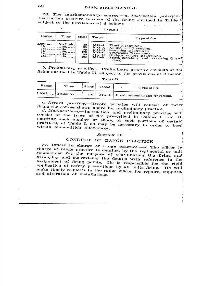
8/22/2019 Basic Field Manual Volume III-1932
http://slidepdf.com/reader/full/basic-field-manual-volume-iii-1932 65/203
58BASIC :FIELD :MANUAL
76. The marksmanship course.-a. In8truction practice .....
InstructIon practice consists of the firing outlined in 'ruble 1,
suhjeet to the pl'ovisions ()f d below:
TABI.E I
Range I Time ShotsType of fire
,000 in •. Xo limit.Do ..•. .do. .•
Do .• _._ •• do._ •••.Do .••.. .• do ..•..Do ..•. •• <tn_ .•.•Do .••••. _.do ••••
3035
l'\O
120
"0
300
l\TG-Al\IO-AMO-BMO-CMG-D
MO-E
Fixed (3 exercises).Adjustment (l exercise).Sl'archinR (2 exercises).']'raversinK (3 exercises).Obl1<lue traverse (2 exercises) ..:Fixc( , searching, and traversmgcises).
(2 exer'
-b. Preliminary rJt'actice.-Preliminary practlec consists of the
tiring outlined in Table II, subject to the provisions 'of d beloW:
TARtE II
I,OOOln._. 3 minutes_ •• 150 MG-E Fixed; searching and traversing.
Hange Time Shots Target Type of fire
-c. Record rH-acfice.-H('cord practice will consist of twice
firIng the courSe shown above for Jlrelhninury practice.
d. Jlodi/icatioIl8.-Instructlon anti pl'ellminary r1ractlce will
consIst of the h'pes of fire prescribed in 'rables I unll II,omitting f'uch numher of shots, or such portions of certain
pl"Uctlce~, of Table I, ns may be necessary in order to keepwithin uIlllllunitIo'n allowances.
I
1
S~:CTlON IV
COXDCCT OP ItANOm PHACTICm
77. Officer in charge of range practice.-a. The officer ill
charge of range practiee is detailed hy the regimental or unit
<'ommanl1er for the purpose of coordinating the firing and
arrang.ing and sUIWrvising the uetails with reference to the
assIgnment of firing points. lIe is resIlonsihle for the rigid
application of safety pl"('cautlons by all units firIng. lIe wIIl
make time]~' requests to tlte range oflleer for repairs,. sUIlplies"
and alteration of Installations.
'
~ _
__ _ -
_ _ __ _
__
_

8/22/2019 Basic Field Manual Volume III-1932
http://slidepdf.com/reader/full/basic-field-manual-volume-iii-1932 66/203
BASIC FIEI~D 1\IA:XUAL 59
b. During record practice he will be assisted by officers de-
tailed by tlle regimental or unit commander for duties on the
firing line as prescribell in paragraph 114.
c. During record practice lie will render decisions upon inter-IJretation of the rules governing re('ord practice which may he
l'~ferred to lIim.78. Range officer.-Successful operation of a machine-gun
rUllge requires the appointment of a range oUlcer well in ad-
vunce of runge pructiee. 'I'he chief duties of the range officer
ul'e as follows:
a. To make timdy estimates for material and labor in orderto 111aeetile range in proper eondition for tiring.
1).To supervise Hnll direct )'('pairs to im.;tallation~.
(~.To regulate the distribution of ranges and targets.
d. To maintain a storeroom where the materials requin'u
rHay be seeul'ed.C. 'Vhen safety delllands, to instruct and supervise range
J.:Uards.79. Company commander.-The machine-gun company <.'0111-
111111111('1' eondue1s the firing of his unit and is re:-:ponsible for
tll(~ ('ffieiency of its training.80. Safety precautions.-a. Firing will not lwgin on any
range until the offiN'r in eharge of range praeti('e ha~ u~.;('er-
tlli1led that the range is ell'ar and has given his authority.
11. No firing will lw done exc('pt under the direct supervisionof an offie('l'.c. No gun will he loaded or half loaded until a command to
(In so lias he<~ngiv('n.d. No gun will he lliSlllounted ufter firing until un officer
J IUi'l il1~11e\'t('dt to ~('e that it is unloaded.
c. No Jl('r~on will he allowed in front of the guns for any
)lurpose unt 11 dirp\'tn] by un oilie('r who has ordered tbat all~llllS III' dpared IIml has us('prtaiIj('d that tile order hus been
l'OIll11letelycurried out.,. ] hl1lger flags will 1)1'disl)la~'('d at prominent positions on
the run!?:eduring all firing.
fT. Suell range guards 11:'\ may he n(,fl<lt'llwill he po:-:tetl.
81. Uniform and equipment ...:-The uniform and equipment
to h(' worn during range pru('tiee will be prescribed by theJ't'gimental or unit communder.

8/22/2019 Basic Field Manual Volume III-1932
http://slidepdf.com/reader/full/basic-field-manual-volume-iii-1932 67/203
GO BASIC :1"IELD MANUAL
82. Use of T base and sandbags.-Tl.le tripo<ls will be
mounted on a woo<len T base; sandbags will then be place
on each l<,g to steady and hold the gun to minimize vibratioIl.
Concrete T bases will not be used.83. Targeting the gun.-a. Before any barrel is used ill
marksmau!'hip firing, it will be targeted with the gun in whid]
it is to he used. The targeting vrocess is for the purpose 0
determining, an<l correcting for, the mechanical error of the
gun and barrel. The zero of a particular gUll and barrel i
the sight setting which will cause the center of impact of sho
groups mude by it to coinci<le with the exact aiming poinused. "'ith the nOl1nal gun this sight setting is 441 yards fO
1,000 i~ehes. By reason of llI11nufaefuring iml1erfeetions mo!'
guns have a zero other than 441 yar<ls. ..
b. (l) Firl~ a burst of 10 roun<ls 011 a target 1,000 incheSfrom the plntle of the gun.
(2) Determine by inspection the center of impact of theburst.
(3) Manipulate the sight (without moving the gun) in
elevation and direction until the line of sighting is on thecenter of impact.i
(4) Lower the sight leaf; loosen the screws holding the
sight-adjusting plate, and place the tips of the blades exactly
on the 441 graduation; make sure that both blades are se
in prolongation of this graduation (it may be necessary to run
the urift slide up to a range having lines on both branches ofthe sight to accomplish this) ; tighten the screws.
(5) Luy the gQn on an aiming paster and fire a confirming
burst; the (-enter of impact should be exactly at the point oaim.
(6) !\ote and record the (leflection zero.
c. The same gun will usuall~' have a different zero for eueh
barrl'l used. Once a gun anu barrel have been tar~'"eted, it
wIll not orulnnrily be nec('ssary to repeat the operation uuring
the life of the barrel. However, the packing must b~ done
properly, and the head-space adJustment correctly maintained,
In order that th~ Zl'ro may not be changed. 11'01' example, i
has been found possible to vary the position of the group on u
target as much as 4 mils by Wide changes in head-space adjust-
ment alone. Minor repaIrs tQ the gun will not uffeet the zero,
-
firml
both

8/22/2019 Basic Field Manual Volume III-1932
http://slidepdf.com/reader/full/basic-field-manual-volume-iii-1932 68/203
I BASIC FlEW MANUAL 61
IIJUtmajor repairs, such as replacing the barrel extension or
the sight or cover, will necessitate retargeting the gun.
(1.When a gun appears to shoot inac'Curately it should be
l'l'tal'geted.
84. Use of fire orders.-All firing ,vill be initiated by defi-
II/te fire orders; the normal procedure is for the platoon leader
to ~ive the fire orders to his unit. '111egunner will be required
to rl'peat all fire orders. An example of a t~'pical fire order
Iiias follows: SPACE 40, HALF LOAD, RANGE 800, LEFT PASTER,
TRAVERSE, COMMENCE FIRING.
85. Personnel at the firing point.-During instruction and
l'I'l~lilllinaI'Ypractice thegunller, the assistant gunner, and the
('!llIch are allowed at the gun. The noncommissioned officer in
('!large of the gun, if he is not the coach, may be at the gun
\\'hen his presence is IH'eded.
86. Duties and use of coach.-A coach will be at each gun
\lUring instruction and l)l"pliIllinar~' practice. The success of
the instruction will depend to a great extent on the thorough-
Itl'",Sand exactness with which the coach performs his duties.
'J'heduties of the coach are us follows:
ft. To require the gunner to explain the practice he is about
to Perform.
b. To require the gunner to adjust the traversing clamp
. to his tap and to .inspect the gun.
c. To check the sight-setting and la~'lng, requiring them
to be correct.
d. To require the gunner to reset the sights and r~ay the
~Unwhen shifting from one group of targE:'ts to another in the
Nllrneexercise.
c. To observe the gunner's position, holding and manipu-
11ltlon during firing; if necessary, he may stop the firing to
eorrect errors.
t. To observe the target from time to time between bursts
to see that the gunner is controlling the fire.
U. To require the gunner to fire bursts as required for each
target. (A burst is n series of shots fired by one pressure on
the trigger mechanism.)
h. To require the gunner to observe the target while firing,
Ilnll to adjust the fire based upon this observation without
II'lIking through the sights.
8/22/2019 Basic Field Manual Volume III-1932
http://slidepdf.com/reader/full/basic-field-manual-volume-iii-1932 69/203
'
62 BASIC HELD :MANUAL
i. To point out errors and explain their effect upon theexercise.
j. To keep eonstant watch of the adjustment and conditioJlof the gun.
87. Blackening the sights.-Both sights of the machine gUll
should be blackened to overcome the glare whenever the sigMS
are used for either range practice or preliminary instructioJl.
This is done by holding each sight for a few seconds in the
point of a small flame which is one of such a nature that t1
smooth, uniform coating of lampblack will be deposited 011
the metal. Among the most commonly used flames are 11
candle, a piec(~of camphor, shoe paste, a rag saturated with oil,or n carbide lamp.
88. Time Umi ts.-a. Before flring any exercise the gunner
will b(~allowed a reasonable time to examine and prepare biSgun and ('quipment. ,
b. In all firing with a time limit the gun will be half loaded,
l)rio1' to the command or signal to commence firing, the sightwill be rai~ed awl set correctly for the target to be ()ngaged, but
the gun will not be laid on the target. The cOlllpletion of the
loading and the laying will be effected after the command 01'
signal Commence firing.
'c. A warning signal may be g;ven not more than five second:;
before the eXPirati.on of the time lhll.it. ]'iring, will ceasethe command or signal Cease firing,
89. Laying the gun.-After the gunner has examined and
prepared the ('qulpment forfll'ing any exercise in preliminarY
llrnctice, the gun, with the 8ights cOl'l'ectly 8et for the particular
exercise to b,e 11red,will be l..'lid80 t.hat it, wi,ll.be a .ll.lill,imulllOf.
tj (hur'not more 'than 10) mils off in direction, and the same
aIllount In elevation, from the ainiing point 011 which it must
he laill for the initial burst. The gun having ill'en so laId off,
no person 'will make unr 'change In either its elevution 01'
dircctloil until the conllllund Commence firing is given. ThiS
llroc('uure will he followed' in eaeh ('xercise with each individ.
ual gUllJwr. DurIng IH'('liminary Ill'actice the couch will be (11.
rected to lay the gun initially as described nbove. The sightleaf will he rah;('d during nIl firing.
90. Stoppages.-l>Ul'ing llreliminury practice when a stop.
page occurs, the gunner will reduce the stoppage nnd' continue
the firing if nny time remains. The lloncommissioneu officer
at.

8/22/2019 Basic Field Manual Volume III-1932
http://slidepdf.com/reader/full/basic-field-manual-volume-iii-1932 70/203
BASIC FIELD l\lAXUAL 63
hi charge of the gun will note the time r£'quired for the re-
(lUetion of the stoppage and will report the nature of the
NtollPugeto his platoon or company commander.
91. Targets used on the 1,OOO-inch range.-Machine-gun
tllI'gets will conform exactly to the specifications set forth in
tlte lllustrations of these targets. Alterations or additions of
ll.lly kind are prollibited .... (Figs. 24 to 28.) The targets will
Ill!Illade so that the outer bounda ry lines of the scoring groups
Will be distinctly visible from the firing point. A line width
or approximately three-sixteenths of an inch will be used.
1.he dimensions of the groups will be nH'asun~d from the outer
I
dI
d[jIcpQJ
..
Iq. ,
dchi
OJdJj
RANGES 700,900, 1100,1200, AND 1400 YARDS
FIGURE 24.-Machine-gun target A
"(]~es of the j'16-ineh line. The lines used to subdivide a scor-
Itng grou.p Into separate ~;{'oringspaees will be so made as not
to he visible from the firing point. The!"e latter lines will not
('Xeet.'tl one thirty-second of an inch in width. Before being
Ulolpdor record pl:actice, each machine-gun target E will be
ch,'eked by an officer to see that it conforms to the specifica-
tlolls prescribed herein.
92. Observation and adjustment of fire.-a. Tbe best results
III machine-gun firing will be obtained only when the fire can
h~ observed and adjustments made from observation. The
gUnner must watch the shot group as it is being formed to
~

8/22/2019 Basic Field Manual Volume III-1932
http://slidepdf.com/reader/full/basic-field-manual-volume-iii-1932 71/203
64 BASIC FIELD MANUAL
--8---.- •
r6"Ir-9.7"
_!_.~ISqUare .• •
•
IJ
_Ran~e '000 to 5earch Up.1375to search down
FIGt.:RE2l:i.-Machlne-gun target n
I
t.p.21 I I I I I aL.9rr ......r---r-,
---r---TI-Ir---r---r--"'''-'J• I
j.. •••••••••••• -I6 .0 .....••••. i 20.4.
I I
-r-,. -,-, ....... I--r'--.I-r--' "T"""i-fiF. -0-.61" ! -.,.. _uJ--L-..L.-..I.--'---'---'---_r 1:
:12.8"I I •
...
1"--..--,.--,.--,...-,.-,--I -.iB~;3. !! [II : -T-
. i :4.7" .lc: I :
. .j_ ... _.~ ••.•
L 13••.••••••• ..••••• co. 13•..••.•.•. J
RANGES 800.IIOQ AND 1300 YARDSFIGURE2G.-l\[llchlne-gun target C
"--1
r :
' ~ _
~ ~~

8/22/2019 Basic Field Manual Volume III-1932
http://slidepdf.com/reader/full/basic-field-manual-volume-iii-1932 72/203
BASIC FIELD MANUAL 65
e('ure the maximum effect of observation. In making the ad-
~~trnent the location of the center of impact is aseertained;
e gUn is then manipulated to place the center of impact
. --~a.lI II
'1'-- --;.
,~.r.~l. ~~~---4.l0 4.7" 7" L I ;-, ...
13" 1. 1311-U-llIO
RANGE:S 800 AND 1100 Y,l,RDS
FIGURE 27,-Macbine-gun target D
11the center of the scoring space. Precision in securing the
IC('uratedelivery of the initial burst will reduce the need forIdJul5tmentto a minimum. Observation of fire on the 1,000-
-~ t..,, .
I
!/0 .... ,38•
.-",..
IlLs-, ...•0 II
• I
; I
il !••.•• *- .•••
RANGES 1300.800.1000.& 900 YARDSFIGURE 28.-Machine-gun target E
Ch range is relatively simple because the entire shot group
11be sepn with respect to the sC(lring spaees. Adjustment
tile gun and tripod to secure a compact shot group, locating
•
~
, -
_ ~
j
_ -

8/22/2019 Basic Field Manual Volume III-1932
http://slidepdf.com/reader/full/basic-field-manual-volume-iii-1932 73/203
GG BASIC FIELD l\lANUAL
the line of "fire so that the sun is back of the target, and P
ing. the targets so that the sky line is beneath the scot"
spaces are all important factors in improving the possibil
of observation. One inch on the target at 1,000 incbeSequal to 1 mil; bence for a shot group having a center of
pact 4 im'hes to the right of the target the gunner must aP
two 2-mil taps, moving the muzzle to the left; for a shot g
2 inches low the gunner must elevate the muzzle 2 mils (
clicks) by manipulating the elevating handwheel. The sol
will be given a series of exercises in which he must state
amount and direction of the correction for shot grouPSvarious locations with respect to the target. .
b. Instruction in the classes of fire (eh. 3, Sec. IV) and
nature of the cone of fire (par. 132) will be given in connect
with this practice.
93. Instruction practice, grouping, machine-gun tat
A.-a. Purpo.'te.-The purpose of the grouping practice
machine-gun target A is to teach proper grouping and therect method of delivering the initial burst of fire. (Fig.
b. PractiCe.-This practice is fired as three separate e,
cises. In each exercise the gunner lays on the designated
ing paster and fires 10 rounds as one burst. Upon comPleuo
th~ burst he checks the aim to see if the firing has disturbe
Any three of the four lower scoring spaces of a vertical se
are used. Sight settings to be utilized to strike these four S
ing spaces are 700, 900, 1,100, and 1,~00 yards. The
maintains the proper vosition, keeving his eyes on the tar
during the firing of the burst. Careful attention will be
to his hold. The resulting shot group, to be satisfactory,
be cOlltainro within an oval 2% inches high and 2 inches
(This should be true of any shot group, in any exercise on
1,OOO-inchrange.) Errors in location of shot groups are
to a poorly-mounted or adjusted gun, to incorrect sight set
or la~-ing, or an incorrect hold. .
94. Instruction practice, adjustment, machine-gun ta
A.--a. Purpoxc.-The purpose of the adjustnwnt practice'
machine-gun target A is to tpuch ohservation of fire and
adju:-itment of fire from observation.
b. Practicc.-The practice Is fired as one exercise. The
tlscoring space of a vertical series is used. The correct •
setting for this scoring space Is 1,400. The gunner is
gu
.
gl
sh
'
gi"

8/22/2019 Basic Field Manual Volume III-1932
http://slidepdf.com/reader/full/basic-field-manual-volume-iii-1932 74/203
BASIC FIELD l\1ANUAL 67
ght !!letting which is in error by about 100 yards in elevation
~(l4 mils in deflection, such as Range 1,300, sight right 4 and
, l'equired to lay accurately on the appropriate aiming point.
Ioiel'iesof bursts of from six to eight rounds per burst, not
l eXceed 35 rounds in all, are fired. Firing will cease as soon
It burst is observed to strike the center of the scoring space .
.!! each burst is fired, the gunner observes the strike, and
~en.without altering or .looking through the sights, adjusts
e gun by means of the traversing and elevating mechanism to
i'lng the center of impact of the next burst on the desired
~lnt. If the second burst does not strike in the correct posi-
~n, adjustments are again made, and a third burst is fired.
then the fire has been successfully adjusted, the practice is
I~lllled. The gunner, without moving the gun, adjusts "the
ght until the line of sight is ag-ain accurately on the aiming
~11lt. He notes the elevlltion and deflection settings and an-
~OUn('eshem to the coach. If the exercise is correctly per-
~i'lUedand if the gun has been properly targeted, the eleva-
;lU should be found to be 1,400 and the deflection the zero
: the gun.95, Instruction practice, searching, machine-gun target
I}-u.•Purpose.-The purpose of the searching practice on ma-
.line-gun target n is to teach the proper distributioll of fire over
(le(~parget. (Fig. 25.)
b, I'raetioe.-The searching practice is tired in two exercises.
I the first the gunner lays on the designated aiming point with
!lIght setting of 1,000 yards, and fires 40 rounlls, endeavoring
111stribute the fire uniformly over the 2 by 16 inch scoring
,roup while searching up. The second exercise is fired in a
rllllJar manner while searching down, using a sight setting
. 1,375 yards in la~'ing the gun. A different aiming point
ill he taken for the second exercise. The firing is done in
1~Cel'lsivebursts of about five rounds each, the gun being
eVIlt<~dr depressed between bursts to obtain proper distribu-
on, The gunner watches the target anll makes the adjust-
etlts necessary to maintain proper direction and to obtain
I1lformdistribution. Inasmuch as a very important phase of
Ie rlractlce Is the proper distribution of ammunition over the
)'bOle scoring space in one application of fire, the gunner will
! InHe firing when he reaches the end of the scoring spaces,
th'JUgh be mllY not have exhausted the ammunition allowance.
~
~

8/22/2019 Basic Field Manual Volume III-1932
http://slidepdf.com/reader/full/basic-field-manual-volume-iii-1932 75/203
G8 BASIC FIELD MANUAL
96. Instruction practice, traversing, machine-gun targ'
C.-a. Purpoxe.-The purpose of the traversing' practice
machine-gun target C is to teach the proper distribution of :6
(lver a wide target. (Fig. 2G.)
b. Practicc.-This pmctiee is' fire<1 in three exercises.
the first and third the gunner la~'s on the left aiming poi
of the group with sight settings of 800 an<11,800 ~1ar<1s,eSP
tively, and fires 40 roun<1sin each, endeavoring to distribute tfire uniformly over the 2 by 16 inch gl'OUp while traverlll
from left to right. The second exercise is fired in a simil
manner, traversing from right to left; the right-hand aimi
point Is use<1with a sight setting of 1,100 yards. The firi
is <1one in successive bursts of about five rounds per bur
the gun being change<1 in direction between bursts to obt
proper distribution. The gunner watches the target and ma~
adjustments necessary to maintain proper elevation and obttl
uniform <1lstribution. The gunner will cease firing when
reaches the end of the scoring spaces, although he may not h~
exhausted the ammunition allowance. Care must be taken
insure that' the gunner adjusts the traversing clamp to
tap before he fires the traversing exercises.
97. Instruction practice, combined searching and trave
ing, machine-gun target D~-a. l'urpo.'lc.-The purpose of
combined searching antI traversing exercise is to teach
proper distribution of fire over a target requiring a CO
bination of searching and traversing. (Fig. 27.)
b. Pl'acticc.-This practice is fired in two exercises. In
first the gunner .lays on the left aiming paster with the sig!
set at 800 yards for the lower scoring spaces, or 1,100 yat
for the upper, and fires 40 rounds, endeavoring to distribt
the fire uniformly over the 2 by 16 inch scoring group
traversing to the right and searching up. The right aim
paster will be used for the :second exercise in which the guni
traverses to the left and searches up in a similar
All lessons learned in the searching and traversing exercli
apply with equal force to thi8 exercise.
98. Instruction practice, combination, machine-gun taii
E .-a. l'ur[w.'le.-The purpose of the instruction practice
machine-gun target E is to deVelop further skill in the appll
tion of the fundaml?ntals of machine-gun fire to the
types of targets. (Fig. 28.)
wl
man
sev
8/22/2019 Basic Field Manual Volume III-1932
http://slidepdf.com/reader/full/basic-field-manual-volume-iii-1932 76/203
BASIC FIF.LD MANUAL 69
~.Practice.-The gunner takes his place at the gun witl:..
rOunds in the belt. The gun is half loaded and the sight
: at 1,300 and raised. The coach lays the gun so that it is
tt1ininmmof 5 (but not more than 10) mils off in direction
d the same amount in elevation from the first aiming paster
be Used. The gunner is required to know the proper sight
:t1ng for each group on the target. These sight settings
1,300 for the fixed-fir~ target, 800 for the traversing tar-
, 1,000 for the searching target, and 900 for the combined
\'er8ing and searching target. The groups will be engaged
the gunner in the order named above. At the command
Elignalto commence firing' the gunner completes the loading,
tile gun on the left aiming paster, and then attempts to
[trIbute the fire uniformly over the four scoring groups
i the target. 'Vhen shifting from one group to another he
!
l'elIUiredo reset the sight and lay the gun on the proper
lng point.
o. EJ1Je()ia~reparation.-Before firing, if time is available,
I gUnner should be required to go over the target, simulating
Qttg at the various scoring groups in the prescribed manner.
9. Preliminary practice, machine-gun target E.-Prelimi-
l)r Practice on the machine-gun target E is fired in the
llte Inanner as the instruction practice on the same target,
eellt that there is a. time limit of three minutes, and the
ttnerceases firing when the command or signal is given. This
get Is scored as prescribed in paragraph 112a.
SECTION V
nULES GOVERNING RECORD PRACTICE
00. General.-a. In record practice the gunner takes his
eealone at a gun to fire an exercise with a prescribed amount
I IlnlInunition in a given time. During this practice he mustthe sights, lay the gun, and fire without any aid, coaching,
ll~fSlstancewhatever. The regulations of this section pre-
Ihe the method by which this principle will be carried out,
it rUlings on the more common points •. "rile gun'ner should have a thorough course of preparatory
hllng, a gun in excellent mechanical. condition, and firmly
Ullted, ammunition whleh is the best available, and time tolJecthis gun and ammunition before firing record.
~
~~

8/22/2019 Basic Field Manual Volume III-1932
http://slidepdf.com/reader/full/basic-field-manual-volume-iii-1932 77/203
70 BASIC FIELD MANUAl.
c. Tile general conduct of the firing will be under the di
charge of the officer commanding the organization.
101. Officer in charge of range practice.-The officer
charge of range practice is charged with the resvonsibility
supervising and coordinating record practice in strict
formitJY
with these regulations. lIe will rule in accordance \1'
the regulations on aU points that may arise during reepractice.
102. Order of instruction and record practice.-a.
person will complete instruction and preliminary practice
fore procpec}ingwith record practice.
b. When record practice is once begun it will be cat'to completion before any other practice is permitted.
c. As a rUle record practice will not be fired by any soilon the same day that he fires any vart of instruction or I
1iminar~' practice. However, when the time allotted to rll
praetice Is "ery limited, the otlicer in ('harge of range prac
may authorize reeord firing Oil the same day. Instruction
preliminaQ' practice will not be conducted simultaneotwith record practice excevt on ranges where firing takes pIon a different part of the range.
103. Retargeting.-The provisions of paragraph l02b all
will not be construed to prohibit the retargeting of a gll~
at nny time this becomes necessary.
104. Personnel at the guns.-The use of a No.2, a co
or any other person at or near the gUll while a soldier is firor preparing to fire recor(l practice, is prohibited.
105. Position of sight leaf.-The sight leaf will beraised dming aU firing.
106. Time for inspection.-The gunner will be nllowe
reasonahle tlLle for the examination of gun, ammunition,equipment.
107. Gun and ammunition to be used.-a. The machineand tripod as Issued hy the Ordnance Department will be t
in all firing. Tile Use of additional clamps or applIanceS
any kind on the gun or tripod is i)rohibited. This provi
will not he construed to vrohibit the Use of shims or wasl
for the purpose of keeping the gun or tripod in proper aM
ment. The sights may be blackened. The panoramic S
willnot be used.
~

8/22/2019 Basic Field Manual Volume III-1932
http://slidepdf.com/reader/full/basic-field-manual-volume-iii-1932 78/203
BASIC l"IELD MANUAL 71I~b. 'rhe ammunition used w1l1be the service cartridge a8 i88ue<l
1J the Ordnance Department. It will be carefully examined
l a defective cartridges eliminated. The use of tracer ammuni-
lOUisl))'ohibite(l.
108. Sighting shots.-Sighting or ranging-in shots are
O!libited.
11?9. Accidental discharges.-:-After a man has ta~en ~iS
bllte at the gun for any exerCIse, all shots fired by hIm WIll
\lilt IlS a part of that exercise. The total amount of am-
llnition used in any exercise, including shots fired acciden-
rlJ y, '\ViII 110texceed the amount authorized for that exercise.
110. Use of prescribed aiming point.-The prescribed aim-
POint will be used in laying the gun. In all exercises
fl essitatlng a shift from one aiming point to another the sight
III be re.,se.twith the proper sight setting and the gun relaid
tl\aking the shift.
~111. Firing after command or signal to cease :firing.-In
~lDractlces which are scored, one point will be <leducted from
e SCore of the firer for each shot fired by him after the
!llillarHIor signal to cease firing has been given. In any
eb.case the minimum p('nalty will be five points regardless
the number of shots so fired. The assistants to the officer
Charge of range practice will exact this penalty.
112. Scoring rules.-a. The machine-gun target E is scored
fOllows: Two points are scored for each 2-inch scoring space
t; one point is scored for each hit in a scoring space, but
~t tnore than six hits are counted in anyone 2-inch scoring
liCe. Hits touching the boundary line of a group are counted.
\hit touching the line between two 2-inch scoring spaces is
Illnted in only one space, but the space selected is that which
I
"ea tile greater score to the gunner. The total possible score
200 volnts.
Ib,.A. f!('ore card will be kept for each person firing as a
~ord of the seores made in each part of the preliminary prac-
IIIand record practice find of the total score made in each of
~ioleructices. The qualificfition attainpd and the date it was
(leWill also be recor<1ed. Entries will be made in ink or in-
lble }l{.neil. No erasures will be ma(]e on score cards.
Iterations may be made only by the organization C0111mander
an oiJieer acting as seorer, and eaen alteration will be
thentkated by the signature of the officer who made it.
~
~
~ ~
~
~
~
~

8/22/2019 Basic Field Manual Volume III-1932
http://slidepdf.com/reader/full/basic-field-manual-volume-iii-1932 79/203
72 BASIC FIELD MANUAL
c. In record practice all tal'gpts will be scored by an ofJi
who will enter the score on the score card and authentltthe entry.
d. If a man fires on another man's target in any exerc
he will receive u score for such hits as are shown 011 his (I
targl't, but he will not be allowed to fire the exercise ag:
The man on Whose target he fired in error will be requirefire the eX(>l'ciSI~gain.
113. Stoppages.-(J. When a stoppage occurs which
gUIHwr ('an not reduce hy draWing the bolt hundle to the
and releasing it, he will raise his haTH}and call, "Time."
time remaining for tile exercise will he Jwted mrefullY
tile assistant to the officer in charge of range vractice. ,~ ~
the 8topvage has b('en corrected, the gunner will he a1l0 I
the time r('mnining for the completion of the exerC'is(~as Il
by the otncer at the instant the stoppage occurred, unlesS I
cause of tile stoppage was manifestly the fault of the gUll
In which case the score must stand. In no case will the e
else he refired. Should a breakage otcur the gun will be
targ(.ted or replace(} amI the score com[lleted. ~j
b. If, in the course of reducing any stoppages not due t(1
fault of the gunner, any unfired rounds are l:'jected froIll II
gun, the gunner will be allowed a(lllitional time to
his score aft('r tile expiration of the time limit, Oil the b
of 1.2 seeonds for each round.
c. The otlker in charge of range practice will render I'
deeisions on stoPvages.
d. Before the cOlJJmand Commence firing is given to COIIl
the exercise the gunner will be 11Pl'mitted to relay upoo
target at Which he was firing at the time tile stopl)uge occut'(
114. Duties of the assistants to the officer in charg'
range practice.-A number of officers sufficient tosupe
record praetiee in 8ft'let aeeordanee with' the Vrovisions of
"ecUon will be d~.tail('d to assist the officer in charge of r,
praeUce. 01liecrs for this duty will be detailed from eomp I
not firing. A maximum of two guns ean he supervised by
oflieer. lIe will perform tile follOWing duties in person:
u. Count the ammunition for eHeh' fin'r after lie takeAOl
pl:1ee at tile gun.
b. Chpek tile (limensions of the scoring spncps in accordwith para,g,.uph 91.
'
!
cOlnJ!
'

8/22/2019 Basic Field Manual Volume III-1932
http://slidepdf.com/reader/full/basic-field-manual-volume-iii-1932 80/203
BASIC FIELD MANUAL 73
o. Lay the gun off the aiming point not less than 5 nor more
an 10 mils in direction, by tapping, and not less than 5 nor
ore than 10 mils in elevation by manipulating the elevating
llldWheel,after the soldier has set the sight and laid the gun
I desired. Thereafter, the gunner will not alter the laying ofe gun until after the command or signal to commence firing is
'en. Care must be exercised, however, to have a part of the
Illingpaster visible to the gunner after the gUll is laid off.
fl. Hequire that the gunner pull the bolt handle once to the
flr after the command or signal Commence firing.
e. Be watchful for the occurrence of stoppages and note the
:ll.cttime consumed in reducing tbem. In cases wbere theInner does not complete the firing within the time limit
iCel'tainthe exact cause, and secure a ruling from the officer
Charge of range practice as to completing the exercise.
f. lIe will require that tbe prescribed aiming point is used
l<l Dot the scoring space; for example, the use of a sight
,tUng of 441 yards with a scoring space as an aiming point
~Decificallyprohibited.0. Make the <1eductioll for firing after the command Cease
illg• .
h. Count the total number of shot holes on a target and for
eh hole above 150 deduct three points from the total score
Qde.
t. Count and record the score as prescribed in paragrapb 112.
115. Disqualification.-Any <1eparture from the mandatory'ov!f;;ionsof this manual in firing record practice will dis-
talify the man affected both for pay and qualification purposes.
SECTION VI
JNSTHUCTION OF TAHGI~TS, RANGES, AND EQUIP.
MENT
116. Range construction.-a. The number of firing pointsIII Jepend upon the terrain available and the number of guns
ieh will probably be firing at the same time. For a company
, eight guns eight firing points are desirable. The interval
!tween guns should be approximately 5 yards.
b. On aecount of the small size of the 1,OOO-inchrange a
Cation for it can be found easily. For each target there i~
!quired a level, open space about 40 ~'al'ds in length (in the
980:m o-32--6

8/22/2019 Basic Field Manual Volume III-1932
http://slidepdf.com/reader/full/basic-field-manual-volume-iii-1932 81/203
74 BASIC FIF..LDMANUAL
TRACKS-
TARGETS
CUJ CUJFIRING POINTS
direction of the line of fire) and about 5 yards in width.
can be located 1'0 that the fil'e is delivered into a steep bll
such as the side of a ravine or an artificial bullet stop,
thus eliminate the necessity
range guards. On this range
interval between guns may be
dm'ed to 3 yards when necesSll
On the 1,OOO-inchrange the
observation of strike is obtaill
when the light is f"om behind
target. Since firing is usually d
in the morning or early afternO
the best direction for the line
fire on the 1,OOO-inch range
slightly east of south.
c. On the 1,OOO-inchrangetarget frame may be carried 0
('ar which runs on a light tr
leading from the firing point to
position of the ta rget, a dista
of 1,000 inches (83 feet 4 inclle
measured from the pintle. r
car and track are furnished byFIOt;RE 2n.-Pllln of 1,000 inch Ordnance Department. Hope
muchine-gun range furnished so that the carria
may be drawn back and forth by a man standing at the
point. This facllitatfls target (.'hanges and observation of
snIts. The arrangement of the range and equIpment is shoWIl
.------1000 in --------...,
FIGURE 30.-1,OOO-lnch range
Figures Z> and 30. CarrIages and tmcks are not a necessity
may he dispensed with, tlte targets being supported by sta~
drh'en In the ground at the required distanee from the
point. In eitiler ('a", tile Btake. Bupportlng tile tnrget on
1
fir
.
fir

8/22/2019 Basic Field Manual Volume III-1932
http://slidepdf.com/reader/full/basic-field-manual-volume-iii-1932 82/203
I
BASIC FIELD l\fANUAL 75
1I.1'1'1age or on the ground should be placed fit the ends of the
~'get frame. When placed back of the target they fire soon
ot Out and also interfere with observa tion.
117. Construction and use of T bases.-The following is a
hll1leor the construction and use of T bases:
!a. Make the T base to fit the particular tripod with which
Is to be used.
b. ~Iake the T base of 2 by 6 inches or heavier timber, if
.
~IlUable. Two pieces about 4 feet long are ne.eded for each
k bllRe• The juncture of the two pieces should be a flush,
Ilpe(} joint so that the T base will lie flat on the ground.
c. When the T base has been made, set the tripod on a level
or and carefully adjust it until it is at the proper height
111.1' the normal sitting position and the traversing dial is accu-
tely leveled. Next place the tripod on the T base and accu-
tely mark the location of the cleats of the legs and trail.'
\ltnovethe tripod find carefully cut out grooves of such size
/l.t the cleats will fit snugly in them. These grooves must all
I! or the same depth so as not to disturb the level of the
ll\,ersing dial. The T base should then be numbered to cor-
~llondto the tripod with which it is to be used.
d. In placing the T base at the firing point, carefully level
I!ground and dig a trench whleh will just receive the T base
a leave the top of the base at ground level. P:ace the T basethe trench, level it, and tamp the earth around it to seat it
tnly•
118. Use of the sandbag.-Half fill the bag. Set it on end
d fold the upper half of the bag so that it lies flat along
III filled portion. Place the bag firmly on the leg or trail of
e tripod so that the foMed part of the bag is next to the
({or trail and so that the bottom of the bag rests on the
oUnd. In placing the bag on the trail tamp it down so as
llluke a good seat for the gunner. Two or more bags on the
~sare neeessary to secure a stable mount.
119. Construction of 1,OOO-inch targets.-The following is
gUide for the construction of 1,000-inch targets when the
rllnlllleeDepartment is unable to supply them:
a. '1'he maldng of 1,000-1nch targets cnn be greatly facilitated
I the use of stencils. l'roeure a picee of tin or cardboard
Il~h is Inrge enough to ('ontain one complete group of the
1l~1'8 needed for the target being made. Draw accurately on
the spa('es and aiming points for the target in question, using
~
8/22/2019 Basic Field Manual Volume III-1932
http://slidepdf.com/reader/full/basic-field-manual-volume-iii-1932 83/203
76 BASIC FIELD MANUAL
a straightedge and n sharp pencil. Carefull~1 cut out t
spaces and aiming points. Such a stencil can then be used
make n large number of targets if! a short time.
b. Place the stencil in the proper position on the 1,000-io
target with the boundary lines of the' scoring spaces in tll
proper relation to the edges of the target. With a sharp peIl
uraw in the spaces and aiming points on the target. Remo
the stencil Paste black target pasters on the aiming poill
as located. By use of a black crayon or other means wid
the outer bounuaries of the scoring spaces to three-sixteent
inch so as to make them Visible from the firing point. Drtl
these black lines just inside of the pencil lines showing t
outer boundaries of the spaces. Draw in the. necessary !ill
to subdiylde the group into the required number of 2-inch sc
ing spaces. Use a sharp pencil for making these lines and
not thicken them to make them visible from the firing
Care is required to make the dimensions conform exactlythose prescrihed in Figure 28.
c. Where facilities are available, it will be much betterhave these targets printed.
SECTION VII
ADVICE TO INSTRUCTORS
120. Provisions not mandatory.-This section is Includ
as a guide for officers in charge of machine-gun marksmansllflinstruction and will not be considered as haVing the force-
regulations unless so SP~~ifically provided elsewhere.
121. Arrangement of demonstrations.-a. Demonstratlo~
which are sklUfclly conceived and executed are a great
in increasing interest in the work, which in turn has a dir~
bearing upon the efficiency of instruction. Successful
strations are necessarily short and give the soldier a
picture of the duties he is to perform.l
b. The men who are to demonstrate an exercise should
intelligent, neat, and soldierly in appearance. They should.
carefully rehearsed in the exact duties each will perform
ing the demonstration, and Where time permits they
practice until it is certain that the work will proc('Cd smootbt
and 11lustrate clearly and simply the exercise which the UIl1
Is tb carry out after the demonstration. ,Co Interest is added to the demonstration by including
mon errors, the officer or noncommissioned officer conductill
poi
.
fact
demo
Clean-e
.
dt
shoU
co
'

8/22/2019 Basic Field Manual Volume III-1932
http://slidepdf.com/reader/full/basic-field-manual-volume-iii-1932 84/203
BASIC FIELD MANUAL 77
the exercise indicating the error, its effect, and the proper
action.122. Organization of work.-a. Thought must be given to
the efficient use of time and equipment during all marks-
lnanship training. For all actual work at each gun a maxi-
lnUm of four men can be advantageously instructed, particu-
1urly during the preparatory exercises. On the range during-
actual fii"ing much can be learned by watching others fire.
'rhe requirements for making targets, filling belts, and fatigue
<It'tails will absorb surplus men. Physical facilities, such as
lnachine-gun equipment and range facilities, should be used to
their maximum capacity, subject only to the necessity for
adequate supervision.b. A demonstration platform should be provided in a central
ll(jsitiOll so that the men under instruction may be assembled
qUickly. A roped area is entirely satisfactory for groups of
100 men or less with the limiting factor that all must be able
to see and hear everything that is said or done.
c. A careful allotment of time should be made for each step
in the training. However, the instructor must watch the
llrogress carefully to see that the men master the instruction
thoroughly, and still are not kept at one exercise to the point
of boredom. Frequent rotation of duties within each group,
\\'1th each man performing each phase of an exercise several
tImes is preferable to keeping each man in one position for a
long time.123. Range organization.-a. Systematic organization of
\\'ork and layout of equipment is necessary for efficient instruc-
tion. Range practice should proceed in an orderly manner,
and the whole organization plan should be developed with
this end in view. Thought and study by the officers conducting
this instruction will go far in securing this desirable end.
b. Belts should be loaded and targets constructed so that an
adequate reserve is on hand at all times .. Time may be saved
by plainly marking the loop ',,"hich holds the last round of
the 150 for record practice. The requirements for all spare
(Iurts and equipment must be foreseen so that firing need not
be stopped because of failure to anticipate needs.o. Tbe ground around all gun positions should be kept clean,
l!lnootl~,and well paclted. A sack or cloth should be spread
Under each gun to catch empty shells; this will facilitate their
Collection and keep them from being filled with dirt. A rack

8/22/2019 Basic Field Manual Volume III-1932
http://slidepdf.com/reader/full/basic-field-manual-volume-iii-1932 85/203
78 BASIC FIELD MANUAL
or box should be provided for keeping the belt from getting
in the dirt as it comes through the gun during firing.
d. Cleaning raeks or tables should be provided for each gun
or group of guns WhE're guns and equipment can be cleaned
or repaired without danger of falling in the dirt.
e. An adequate supply of clean water should be provided forrefllling water jackets. .
,. AU of the points to be observed before, during, and after
firing, as prescribed in paragraph 24, should receive careful
attention and have a definite place in the schedule of work.
u. The packing of the balTel should be frequently inspected
and rpplaced when necessary. The front packing should re-
ceive particular attention, for it exercises a great .influence on
the nature of the shot group made by the gun.
h. The prompt publication on the company bulletin boards
of the seores made in preliminary and record practice will be
of great value in stimulating interest and arousing a spiritof cOJllpetition.
i. Men who are not actually engaged at the guns during fir-
ing or detail<'d on other duties should observe the fire. Benches
should be provided in rear of the guns so that men may sit
in comfort rather than stand or sit on the ground or ammuni-tion and water boxes.
124. Adjustment of gun and tripod.-a. During range prac-
tice each gun and tripod should be properly adjusted, mounted
firmly on a substantial T base, and the tripod weighted down
with ~andbags in order that the gun will group closely. Since
the purpose 'of marksmanship is to master the four fundamentals
prescrib{'(l in paragraph GO, instruction is greatly simplified
by providing £>quipmentin perfect mechanical condition.
b. Looseness and play in the gun must be. reduced to a
minimum consistent with proper functioning. This is accom-
plished with proper packing and tightening the. muzzle gland.An incorrect h{'ud-spaee adjustment affects the size of the
shot group. ""orn or bent parts must be corrected or replaced.
Play iuthe sight or Cover affects the accuracy of aim. Shimi'l
should be inserted around the elevating pin or trunnion pin
if an~' loo~'ne8s is pre~{'nt. The brass slide in a cartridge
clip is excellent material for this purpose.
o. Several parts of the tripod reqUire attention. In a tripodwhich has been in use for an extended period the sides of
the cradle should be forced inward so that the trunnion block

8/22/2019 Basic Field Manual Volume III-1932
http://slidepdf.com/reader/full/basic-field-manual-volume-iii-1932 86/203
BASIC FIELD MANUAL 79
is firmly held. The elevating mechanism must be withoutunnecessary play; this can be corrected by tightening the'
tumbler collar under the elevating handwheel, and by insert-
ing shims around the tumbler trunnions. The serrations on
the tripod legs must be sharp.
d. Once a gun has been properly tightened and adjusted it
8hould 110t be removed from the cradle. At the close of
firing the traversing clamp can be loosened, the gun and cradle
being lifted out together. This eliminates the necessity for
daily adjustment and saves time.
125. Inspection of ammunition.-Care should be taken to
See that the best ammunition available is reserved for record
Practice, and that all ammunition Is carefully inspected before
It is used so that obviously defective cartridges can be elim-
inated. If 'this is done, the firing will be more accurate, the
guns wlll function better, and there will be much less trouble
from stoPl)ages. For record practice, especially,. every round
8hould be examined. This can be accomplished by having each
lnan examine his own ammunition while awaiting his turn to
fire. The following points should be covered in inspecting the
ammunition:
a. That it is properly amI evenly loaded in the belt.b. That the bullets are all tight in the cases; loose bullets
tan be detected by attempting to twist them.
c. That the cartridge cases are clean and free from bulges,
dents, or spilt necks.
d. That the bullets are not shoved so far into the case ns to
make short rounds.e. That the rims are not too thick and are not battered.
126. Spare barreis.-An :HI~'qllat(~ supply o( sei;,;Ice:lIil(' ,in-I::'
l'eJs must he on hand for lIlarksm:inship fIrin,a-. The 8"ccuracy
life of barrel depends on the care and attention which it'
receives. In firing at aerial targets it is important that the.
Water jacket should be completely filled with water. Barrels
Which have been used for firing approximately 8,000 rounds
of ball ammunition which are badly eroded and pitted, or
Which have been used for firing a large quantity of tracer
ammunition should 110t be used. For marksmanship firing
. and for firing at aerial targets such as free balloons, where
the balloon release detail is in advance of the guns and not'
r.ompletely protected, the accuracy life of a barrel is placed"
""hO"~ fihould be, if available, one barrel'.---.-.l..;n 'course.
~

8/22/2019 Basic Field Manual Volume III-1932
http://slidepdf.com/reader/full/basic-field-manual-volume-iii-1932 87/203
82 BASIC FIELD MANUAL
131. Value of direct laying.-The possibility of observing
the target and the effeet of fire, and the ~onHequeut siluplicity
of fire adjustment, give to direct laying a relatively greater
('fficiency than that possessed by indirect laying. Taking- iutoconsideration the number of casualties inflicted upon the enemy
within a unit of time with a given ammunition expenditure,
it may be laid down as a general rule that fire by direct la~'ing
is much more effective than by indir('ct la~'ing. The former
is the type most often employed in battle. It should alwa~'s
be used in prpference to indirect laying when a practicable
choice exists between the two. However, indirect laying shouldsupplen\('nt diret't laying whenever there is a possibility of the
failure of the latter method on account of smoke or darkness
masking the target.
SECTION II
COXE OF FIRE AND BEATEN ZONE
132. Cone of fire.-a. When a series of shots are fired in a
single burst the bullets do not all follow the same path, nor
do they all strike the same point on the ground. The vibra.
Uon of the gun and tripod, the variations in the ammunition,
and the changes occurring in atmospheric conditions, cause
each bullet to trace a trajectory differing slightly from that of
the others. The resultant group of trajectories is known as
the cone of fire. This cone may be cOlllIlared to the stream
of water frolll a hose. At ranges up to 700 ~'ards over level or
uniformly-sloping ground, the stream of bullets does not rise
above the height of a man standing. However, as the gun
is elevated to fire at the longer ranges, the cone is lifted con.
siderably above the ground. Thus at the longer ranges it is
possible for the gunner to deliver supporting fire over the
heads of friendly troops.
b. As the bullets travel farther from the gun the width of
the cone increases uniformly at the rate of about 2 yards for
every 1,000 ~'ards of range; meanwhile the height increases at
a much greater rate.
133. Beaten zone.-a. When the cone of fire strikes the
ground it forms a long elliptical pattern. This pattern is
!mown as t11e beaten zone. The lengths shown in ]'igure 31
are attained when the cone of fire falls on ground whose
surface Is parallel to the line of aim. The maximum length
Is obtained when the slope of the ground approximates the

8/22/2019 Basic Field Manual Volume III-1932
http://slidepdf.com/reader/full/basic-field-manual-volume-iii-1932 88/203
BASIC FIELD MANUAL 83
angle of fall. On rising ground the width remains the same,
but the pattern is shortened until, on ground perpendicular
to the line of aim, the beaten zone becomes the same as the
\'ertical pattern (cone of fire). (Fig. 31.)
b. The center of the beaten zone is called the center of
impact. It has been found that most of the shots are uni-
FIGURE 3t.-Effect of ground slopes on beaten zone
formly grouped about the center of impact, and that the
number in a given area decreases gradually as the outer
limits of the beaten zone are approache{l. The grouping of"hots is shown in Figure 32. The shots are so scattered along
the outer edges of the beaten zone that the entire pattern is
not regarded as effective. Only that part of the beaten zone
j.--- E.ff.E.CTIV.E. Df.ATEN ZONE.' ----tlI (est. ZONE.) I
:~'.'.:::;\'.'i'Y~;rt(;:.i,:(~I CE.NTE.R OF IMPAC.T II. IIt . 10010ZONE
FIGURE 32.-Distribntioll of shots in beaten zone
2n which 85 per cent of the shots fall is considered effective
against milchine-gun targets; this area is known as the "85
Per cent" or "effective" beaten zone. It is obvious that the
maximum effectiveness can be obtained only when the center
of impact is placed on the target. The machine-gun sights are
graduated so that when the gun is laid on a point, with the
('orree! sight setting, the mean trajectory, or center of impact,
8hould'strike that point. The gunner is taught to do this in
lnarksma nship.c. FIgure 33 shows the approximate dimensions of the effec-
tive beaten zone on ground surfaces parallel to the line of aim
at the key ranges. All machine gunners must know these
'

8/22/2019 Basic Field Manual Volume III-1932
http://slidepdf.com/reader/full/basic-field-manual-volume-iii-1932 89/203
84 BASIC FJELD MANUAL
l::fOO
dimensions as a basis for estimating the lengths of effectivebeaten zones on varied terrain.
d. Throughout this chapter whenever reference is made to
the beaten zone it will be llnderstooll to mean the effective
beaten zone, unless othenvise specifically indieated.
50~"".2000
FIGURE 33.-Table of approximate effective beat~n
Zones on gronnd parallel to the line of aim forM1906 ammunition (triO-grain bUllet)
SECTION III
RANGE DETEU:\IINATION AND WINDAGE
134. General.-Correct range determination is highly im-
llortant for efficient machine-gun fire, since it is often impossible
for the gunner to adjust his fire because of damp ground or
poor visibility. In such cases the cone of fire may miss the
target completely if there is an error in range no greater than
100 :rards. In direct la~'ing, ranges are usually determinedby estimation, by the use of range finders, or by fire foradjustment.
135. Classification of ranges.-a. Ranges are classified asfollows: .
(l) Close, under 700 yards.
(2) Mid, from 700 to 1,200 ~'ards.
(3) Long, from 1,200 to 2,000 ~'ards.(4) Distant, over 2,000 ~'ards.
~
~~

8/22/2019 Basic Field Manual Volume III-1932
http://slidepdf.com/reader/full/basic-field-manual-volume-iii-1932 90/203
BASIC FIELD MANUAL 85
b. Ordinarily ranges vary. from 100 to 1,500 yards for direct
laYing. Practically, the extreme usable range is governed by
the means of determining the range, by the visibility, and by the
tactical purpose of the fire.136. Methods of range determination.-a. Ranges may be
<lPtermined by anyone of the following methods:
(1) Estimating distance by eye.
(2) Range-finding instruments.
(3) Fire for adjustment.
(4) Taking the range from a map.
(5) Obtaining it from other units.
(G) Measuring- the range directly on the ground.
b. In. using direct laying, the methods of range determina-
tion usually employed are estimation, range finders, and fire
for adjustment. Ranges determined either by estimation or
range finder should be ehecked by fire for adjustment whenever
llJ'ucticable. When observation of. fire is possible and surprise
{'fl'ectis not important, determination of the range by fire foradjustment will give the best results, because the gun itself,
Under favorable conditions, is the best range finder.
137. Training in range estimation.-The methods of train-
ing in range estimation prescribed in l)art One, Chapter G, will
he followed. All l)erSonnel of machine-gun organizations should
h(~ trained to estimate distance with a fair deb'Teeof accuracy.
Officers, noncommissioned officers, un(l Nos. 1 and 2 of the gunklJuads should receive additional instruction with a view to
l'(mching and maintaining a high degree of proficiency in this
kUbject. The average of a number of estimates by different men
Will usually be more accurate than a single estimate. Platoon
It'llders should therefore call on their section leaders, and when
0Ilerating independently section leaders should require their
kquad leaders to estimate ranges to the targets whenever a rangetinder is not avuilahle. Experience has proven that single esU-
llllltes of traint:'d men will result in a probable error in range
(h~termination of about 15 per cent, and that the average of the
('~till1ate of several men may reduce this error to 10 per cent.
The'maxlmum error of properly adjusted rang-e finders of the
k('lf-contained base type is 5 per cent. In taking the range
from the map, the error is from 2 to 10 per cent, dependingU[IOnthe methods used und the scale and accuracy of the map.
8/22/2019 Basic Field Manual Volume III-1932
http://slidepdf.com/reader/full/basic-field-manual-volume-iii-1932 91/203
8G BASIC FIELD MANUAL
138. Use of range finders.-Estimation of ranges in exceSs
of uOO yards ('un not be relied Ullon to produce accurate reo
sults, Range finders, therefore, are of great value to machine
J:mnners. .All nonclHumissioned of!ieers should be trained ill
their adjustnwnt, cat'e, alld use.
139. Fire for adjustment.-a. Meth()d,~ of executin[J {lre.-
(1) To execute fire for adjustment when observation is good,
the gunner opens fire at the estimated range, rolls the strike
into the target by means of the elevating mechanism, sd~
the rear sight so that the line of sighting is 011 the corrected
..trike on the target, Ilotes the sight setting on the rear sight,
und announeps it as the range to the target. All guns al'e
Uwn laid :nul fire is olwned by command of the unit leader.
(2) When the groulld in the vicinity of the target, for anY'
reason, permits no observation or When it is desired to sur-
prise the targl't with fire, the gunner may alljust on a point
which does oft'er observation and whieh is the saIlle lli8tallce
away as tl:e tat'get IJoYpl'oeecding us eX£llllined ill (1) above.
The gunnel' swings his gun on the targ('t When ordered.(3) When l'ngngLg targets in trpcs 01' huilllillgs, fire
adjustment is fit'st applie(l to the ground at the foot of
tree or bUlIding. The range thus determined is taken as the
range to the target. The gunner UlIllounces the runge awl
elevates hi8 gun until laid on the target. I
b. Limltalions.-It must be borne in mind that fire for
adjustment may remo\'e the element of suqlrise Hnd causea betra~'al of position and intention. It should therefore
used only at the longer ranges 01' where surprise is not an
hnIlOrtant elemellt. Pire for adjustment should not be emplo~'ed
against ra{lidi~' lUoving targets and those whil'h can evade fire
for effect during the pause for ohservation and cOl'l'ectlon.
c. Use.-Against llOsitiOlls such as wootls, trenches, or oUlPr
organized at'eas, fire for adjustment should be employed.;It should be the rule to employ fire for adjustment on every
practicable o('('asioll when it promises a more etlicacious fire
effect. "
140. Windage corrections.-a. "The amount by which the
path of the cone of fire is defiected from its normal path de-:
Il('nds upon the force and direction of the wind and the range
to the target. The amount of windage required to correct for
be,
'
"

8/22/2019 Basic Field Manual Volume III-1932
http://slidepdf.com/reader/full/basic-field-manual-volume-iii-1932 92/203
BASIC FIELD MANUAL 87
a 3 o'clock or 9 o'clock wind having a velocity of 10 miles auhour, when using MHlOO,cai. .30 ammunition, with the 150-
grain bullet, for the key ranges is shown in the following
table:10-tnile teind fron~ 3 o'clocl~ or 9 o'clock
Range: Correction (mils)500 11/2
1,000 ---------------------- 41,500 .;.____________________________ 7
2,000 --_____________________________ 10
1). The f'ffect of winds. of other vPlodties or at other ranges
nlay be approximated by an inspection of this table. For
r1rnctical purposes the effect of a wind varies directly as its
force. For example, a 20-mile wind would require twice the
correction. shown for the various ranges. \Vinds that are one
hour away from 3 o'elo{'k or 9 o'dock (considering 12 o'clock
to he the direction of the target) require slightly less wind-age correetion than 3 o'dock or 9 o'(']ock winds. \Vinds that
are one hour away from G o'clock or 12 o'clock require slightly
l~~!ishan one half as much windage correetion as 3 o'clock or
\) o'clock winds.c. In the fire order, windage correction Is announced im-
lliediately after range as .. SIght right (left) 5."
SF:CTION IV
CLASSES OF FIllE
141. Classes of fire with respect to gun (fig. 34).-a. FIxed
fire is that fire in which the beaten zone Is not increased in
\\'ldth or depth by tnlYersing or searching. The elevating
Qnd traversing mechanisms may be clamped so as to limit the
dispersIon of fire. Fixed fire is emplo~'ed against small targets,kUeh as machine guns u('flnitely located, small columns, groups
(If men, bridges, roads, defiles, and trenches.
b. 'l'raversing fire is fire distributed In width by successive
('lIanges in dIrection of the gun. It Is used to engage lines,
trenches, edges of woods, and other areas presenting wIde
targets ..
c. Searching fire is fire distributed in depth by successivechanges In elevation of tile gun. It is emplo~'ed against deep

8/22/2019 Basic Field Manual Volume III-1932
http://slidepdf.com/reader/full/basic-field-manual-volume-iii-1932 93/203
88 BASIC FIELD MANUAL
r
T
targets such as columns, trenches, and edges ~f woods takeVin enfilade.
d. Combined traversing and searching fire is fire distributed
both in width and depth by succeHsive changes in direction and
elevation of the gun. It is employell against oblique targetS,142. Classes of fire with respect to target (fig. 34).-0'
Frontal.-Frontal fire is fire delivered at right angles to the
OIRECl"ION OF
MARC'"'
4z:rua
T T
T
fIXE..D' StAQCHlf1G TRAVI.R5If1<i f120rITAL OBl.lQUE. ~NfILADE. fLAtU\\Ku
~.", ;;QAZI~~-~
Z,'IGl:UE 34.-Classes of fire
tront of the objective. If the target has little depth, such as
line of skirmishers, frontal fire is the least effective type OJ
machine-gun fire since the long. axis of the beaten zone
at right angles to the long axis of the target. Frontal fir
dcli,ered against the head of a column advancing directlf
toward the guns is, however, highly effective fire. This
of fire frequently has to be employed in the attack becausethe fact that the area in Which guns may be placed is limited.
i
clas
o

8/22/2019 Basic Field Manual Volume III-1932
http://slidepdf.com/reader/full/basic-field-manual-volume-iii-1932 94/203
I
i
I
BASIC FIELD MANUAL 89
'\Vhere this area is not restricted, frontal fire may be obviated
b3" Nacing the guns so that their fire will be oblique or flanking.
b. Oblique.-Oblique fire is fire delivered at an objective from
a direction oblique to its longer axis. It is generally more
N'fl.Ctivethan frontal fire because more of the target is in-
elUded in the beaten zone of each burst.
c. Fla,nking.-Fire delivered against the flank of a target
If!<'aIled flanking fire. When the long axis of the target is at
l'ig!lt angles to the direction of fire, as in the case of a section
('O!UTnnttacked from a flank, flanking machine-gun fire is not
"ery effective, since only a small part of the target is coincident,
Ol" nearly so, with that of the beaten zone. On the other hand,
III a skirmish line engaged from its flank, this fire becomes
Obliqueor enfilading (d below) and is highly effective.
I d. En{ila.de.-Enfilade fire is fire, either frontal or flanking,
I in \\'hich the long axis of the target coincides, or approximately
('Olncides,with that of the beaten zone. It is the most effe~-
U"e type of fire. Columns approaching the gun and lines en-
~ag('d from positions on their flanks are said to be taken in
~l1ftlade. Troops taken in enfilade at shorter ranges form the
deal machine-gun target.
143. Classes of fire with respect to ground (fig. 34).-a.
Plun,fJing flrc.-l'lunging fire is that fire in which the angle
Of fall of the bullets with reference to the slope of the ground
(or other object) struek is SO great that the danger space is
Il.11Vroximatelyequivalent to the beaten zone. At the closer
I'll.ng-eslunging fire results from delivering fire downward from
high ground on such ground as lies nearly at right angles to
the cone. Such fire may also result against ground which
1'1!i(~1i sharply to tIle front with respect to the position of the
~Un. At the longer ranges, fire becomes Increasingly plunging
Ill! tile angle of fall of the bullets becomes greater.
b. Gra.zing.-(l) Grazing fire is fire which is approximately
b1tl'UIlelto the ground and does not rise above the height of
nlQn standing.
(2) A band of fire is fire, grazing, at least in part, and
l'C!ferably from the muzzle of the gun to the farther end
It the beaten zone, delivered by one or more guns with
he Mme mission.
. 144. Effect of proper location of guns.-ordinarily the posi-
Ion of the target with resped to the gun ruther than the
98fl53°-32--7
8/22/2019 Basic Field Manual Volume III-1932
http://slidepdf.com/reader/full/basic-field-manual-volume-iii-1932 95/203
~o BASIC :FIELD MANUAL
shape of the target will determine its vulnerability to fire
For example, a skirmish line engaged by frontal fire is a
target, whereas, if aUaeked from a position on the flank,
may be a good target. As the enemy will never knowing!.
present deep enfilade targets, it must be expected that these Wi
usually be obtained by skillful selection of gun positions.
SECTION V
TARGliJT D"U~SIGNATION
145. Preliminary training.-Before taking up the subject
target designation, maehine gunners must be familiar with tll
military an(l topographical terms emplo~'~d in designating
gets; for example, cre~t, hill, cut, ridge, crossroads, right, let
flank, skirmishers, column, and patrol. The soldier should a1•
be instructed in the meaning and use of such terms as bO
zontal, vertical, above, below, rectangle,' square, triangle, 111
)Oard,and pace. Before practical work in target designation
taken up, a thorough course in visual training and range eSmation should be given. The soldier must be taught.to use }1
eyes 8ml retain mental pktnres of what he sees.
146. Methods of designating targets.-a. Traccr ammU
tion.-Targets may be designated by flring traeer ammuniti
from rifles and pistols. Ritiemen llIay fire tracers to pol
out targets to machine--gun leaders who have just come up"
b. Bursts of firc.-When observation is good, machine gUners who have located the target may fire bursts to
the location of fianks of any enemy target to machine gU
which have just com;::into position.
o. Leader layi1;g the gun.-The leader may lay one or roO
guns on indistinct targets or he may lay one gun and fire
cautioning the remaining gunners to watch his burst. Tb
method usually gives best results, especially when speed
essential.
d. Oral descriptlon.-This is the usual method of designati
targets.
147. Oral designation.-a. Sequenee.-Tlle essential partS
an oral designation are announced in the following sequen
Ran~e.
Dir(~tion.
Description of target.
'
pO
t1
indic1

8/22/2019 Basic Field Manual Volume III-1932
http://slidepdf.com/reader/full/basic-field-manual-volume-iii-1932 96/203
BASIC FIELD :MANUAL 91
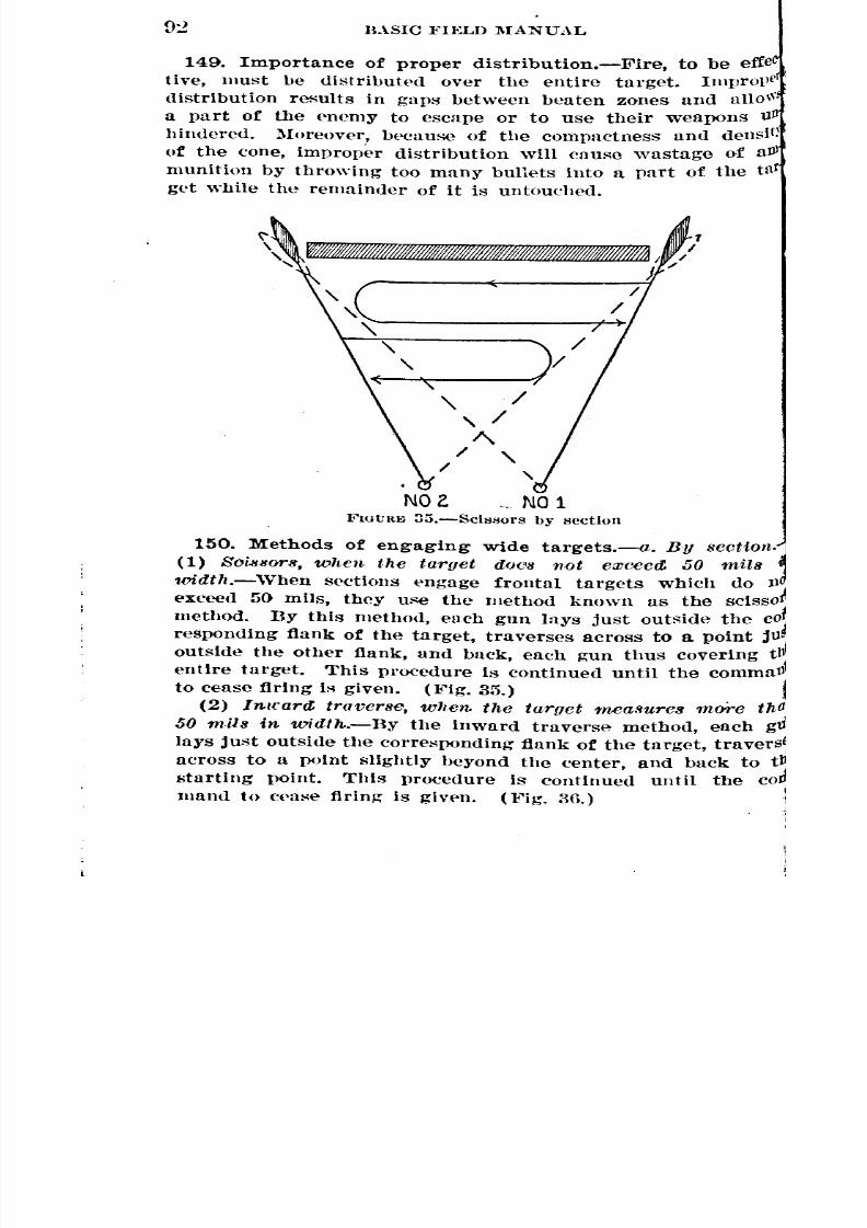
8/22/2019 Basic Field Manual Volume III-1932
http://slidepdf.com/reader/full/basic-field-manual-volume-iii-1932 97/203
BASIC FH:LD MANUAL
149. Importance of proper distribution.-Fire, to be effe
tive, must be distributed over the entire target. Imprope
distribution results in gaps between beaten zones and aIlo"-'
a part of the enemy to escape or to use their weapons Ull
hindered. Moreover, because of the compactness and densit)
of the cone, improper distribution will cause wastage of aJll
munition by throwing too many bullets into a part of the tllt
get While the remainder of it is untouched.
NO e ". NO 1I'~GURI;} 35.-Scll:l80rS by section
150. Methods of engaging wide targets.-a. By section.
(1) Soissor8, when the target doC's not exceed. 50 mils
1vidth.-When sections engage frontal targets which do J l
exceed 50 mils, they use the method known as the scisso
method. By this method, each gun lays just outside the CO
responding flank of the target, traverses across to a point j1l
outside the other flank, and back, each gun thus covering tll
entire target. This procedure is continued until the commaIJ
to cease flring is given. (Fig. 35.)
(2) Inlfartt traverse, when. the target meaSures more th
50 mils in. widtn.-By the inward traverse method, each gtl
lays just outside the corresponding flank of the target, travers
across to a point slightly heyond the center, and back to tstarting point. This procedure is continued until the co
mand to ('('ase firing is given. O'ig. 3G.)

8/22/2019 Basic Field Manual Volume III-1932
http://slidepdf.com/reader/full/basic-field-manual-volume-iii-1932 98/203
BASIC FIELD l\1ANUAL 93
(:3) Swinging traverse, when the target, 8lUJh as cavalry or
Ifantry, is moving rapidly towarit the guns at short range.-
the swinging traverse method, each gunner loosens his,a\'(l"/iingclamp a sufficient amount to permit traversing the
llJ. by placing the weight of the body against the grip, and
~t by use of arms only, and each gun is laid on any portion
; th!~ target, and traversed, firing continuously. This type
. fir!., however, is wasteful of ammunition, and should be used
13'Under the conditions indicated above.
NOlo N01
FIGURE36.-Inward traverse by section
• /)11platoon.-(l) Scissors, 'lellen the target measures less
100 mils in width.-Dy the scissors method, each section
~lijllllycovers its corresponding half of the target as pre-
~bed for scissors by section. (Fig. 37.) The platoon leader
It,' Ilowever, order the right section to cover the left halfhe target, and the left section to cover the right half forfOllowing purposes:
:) ~'o secure oblique fire.
) In order to shoot through a gap in the line of riflemen.C) In order to obtain safety for overhead fire or to avoidhelld fire.
) Inward traverse, 'lclten the target measures more than
tn-flll in 'It'idth.-n~, the inward traverse method, each sec-
~
'"

8/22/2019 Basic Field Manual Volume III-1932
http://slidepdf.com/reader/full/basic-field-manual-volume-iii-1932 99/203
94 BASIC FIELD MANUAL
NOoeO::!O 4
tion executes inward traverse on its corresponding hulf of
target, or the platoon leader may order the fire of the secti
to be ('1'o8sed, as explained in (1) ahove. (I<'ig.38.)
FIGtJRI<: 37.-Scil;sors by platoon'
151. Methods of engaging targets takt'in in enfilade.
Gencral.-"Ko enemy will knowingly'present an enfilatle t!l
to machine-gull fire; but if lie does happen to present st1e
N04 NeZ. N01
FIGt:RE 38.-Inwurtl traverse by platoon, showing croHslng'
of fire of sections to secure oblique fire
tar~et, he will qUickly (kploy when fired upon. lIence
method of engaging enfilade targets, to be etncient, must be
which can be quickly and readily applied. Further!ll
~

8/22/2019 Basic Field Manual Volume III-1932
http://slidepdf.com/reader/full/basic-field-manual-volume-iii-1932 100/203
i
BASIC FIELD MANUAL 95
Ilners must be trained to follow any changes in formation
~<leby the enemy after the initial bursts of fire•
• [l1ixed fire.-Targets. having 'little depth and located on
r"er ground at short ranges can best be engaged with fixed~. The depth of the beaten zone ,vill ordinarily be suf-
ent to cover effectively enfilade targets of this character.
the ground is rising to such an extent that the beaten zone
°Ines shorter than the depth of the target, searching will
I'eto be used.' ,
o.8carchingfire.~(1) By sectiCJn.-Targets having consider-
lie (l<~Pth,or located at ranges such that the beaten zone of
inl11vidual gun is shorter than the depth of the target, may
e1lg-ag{>dy a section as follows:
]'(0 eo
C) . . . . - - - - - - - - =4OJ r
FIGunE 39.-Sectlon engaging n depp ('nfilade target
(Q) If "t.he target is stationary, h~s limited' niobility, or is
o\'ingslowly, the gunner of No.1 gun la~'s on the near end
bd !Searches up; the gunner of No.2 gun lays on the far end
1<1 searches down. (Fig. 39.) ,
I:b) ,If the target is moving ~apidly' away from the guns,
h gunners lay on the far end and search down.1(0) If the target Is moving rapidly toward the guns, botll
llners lay on the near end and search up.
~2) By pla.toon.-A platoon uses the same method as the
otlon, each section engaging the target as if it were actingIle. In case it becomes necessary to switch the fire of one
,tton to another target, the original target Is thus covered
4the remaining section. ,
. 4rnount Of search.-In case the conditions of the ground
IQ \>i8ibllity are such that the gunners will be able to st>e
strike of the bullets, the amount of search should not be
en. The gunners keep' their fire on the target as they
:I'Ch hy observation. If, however, the strike can not be seen,
I
amount of' search may be prescribed. The following 'rulethe 1\11900ammunition (150-graill bUllet) may be used to
el'tnine the proper number of mils of search:
(1) Measure or estimate the depth of the target in ~'nrds.
~
~
~~
~

8/22/2019 Basic Field Manual Volume III-1932
http://slidepdf.com/reader/full/basic-field-manual-volume-iii-1932 101/203
96 BASIC FIELD MAKUAL
(2) Divide this b~' the number of yarus change in rll
caused b~' a change in plevation of 1 mil for the range to
center of the target. This Uivisor can be estimated froUl
fonowin~ table:
nange:
1,000_____________________________1 mil pquals 30 yll1,::iOO 1 mil equals 20 yll
2,000 1 mil equals 10 yll
NOTE.-The fi~res are based on ll'ngths of beaten zones sho"
Figure 33; allowances must be made for the effect of position and
For example: An enprny column, estimated to be 200 yards long, Ifilllded by a section of guns at a range of 1,000 yards. 'l'he col
coming down a gl'ntle tllope. The proper amount of search shoU
6 or 8 mUs (200/30 equals 7 mUs).
--<....
- --ROt. 00:::_
NO 1
- ~}<'IGVRE0.-Sectlon engaging a short oblique tar-
get (using section scissors)
152. Methods of engaging oblique targets.-a. If the
of the target is less than that of the beaten zone, a secti0platoon uses the seissors or the inward traverse method,
l)('n~Ungon the width of the target as seen from the guns.
-tt:: ....
:::~._-FIGVRE41.-Sectlon engaging a long o1Jlique target (uslna'
inward traverse and Sl'arching)]
rule that not more than 1)0mils of front should he ass
a single gun determines which method will be used. (I\'ig:b. If the depth of the target is greater than the beaten'
combined traversing and searching must be used. Sdssotinwa I'd trawrse is combined with searclllng. (Ii'ig. 41.)
uJl
(
_ __ - ~ •
~
l

8/22/2019 Basic Field Manual Volume III-1932
http://slidepdf.com/reader/full/basic-field-manual-volume-iii-1932 102/203
BASIC FIELD :MANUAL 97
l153.Methods of engaging point targets, or targets cover-
I~El1ll.allreas.-a. If the target is clearly visible and will be
I~lI(h'd in the beaten zone of a single burst, and if the range
,:ceUratelYknown, fixed fire may be used.I . If it is desired to cover a relatively small area in the
bClnity)f some object such as a bush or a tree, and it is not
\tfSlbleto define clcarly the limits of the area so that the
fSSOl'S method can be used effectively, the area may be cov-
d by a section fiS follows (fig. 42) :(1) The section leader anno~nees the total amount of trav-
8e and search, if search is neeessary. Each gun la3's on,e Ohjeet used as an aiming point, or on the center of the
(lQ to be covered. The right gun of the section traverses
No 1 GUM
FIGURE 42.-:;\lethod of eugaging small area target
the right one half of the announced traverse, searches up
lnllH, then traverses left the full amount ordered; it con-
~ueH to search up 2 mils at a time, and traverses the entire
11th of the area until the upper half of the total area has
n (~overed; it thpn sefirclles down and traverses, covering the
Itire area. '1'he left gun starts traversing to the left, and,
!ItChingdown 2 mils at u time, covers the lower half of the
~!U before searching up and traversing to cover the entire
t'eI'U, The operation is continuous until the command to cease
In~Is given.(2:) If it is desired to cover such an area with u platoon, the
ltul amount of traverse and search is ordered us above. Each
letton covers the entire area exactly as if )t ,,~ere firing
lon(); this requires but oue method of operation for the In-
, \'hlunl guns.(3) If it Is evlc1ent that the target is beyond, short of, or
Oll(! side of, the selected aiming point, or if the ground af-
Il'd~ observation of shots striking short or over, or to one
lle, it mllY be advisable to order the trayerse or search, or
'

8/22/2019 Basic Field Manual Volume III-1932
http://slidepdf.com/reader/full/basic-field-manual-volume-iii-1932 103/203
98 BASIC FIELD MANUAL
both, only in the direction likely to produce hits .. The or
may therefore be in one of the following forms: "Traverse
search up 8"; "Traverse Hight In, search 4"; "Traverse
24,.~earch down 4."(4) Becnuse of the depth and narrowness of the bell
zone, the proper amount of search will usually be much
than the traverse.
154. Combined sights.-a. General.-(l) Combined sl
i~ a method of engaging a depv target hy means of twO
more guns which Use the same niming point with (lifferent
vaUons set off on the rear sights. 'This proeedure maYemplo)"ed as well to insure hitting a target whose exact I'll
Is not known and which might be lost if fire for. adjustll
were used. Guns laid with combined sights. may fix, seH
or tra verse.
(2) Comhlned sights should not be regarded as a cure-all
poor range determination and poor Observation. It Is relati
wasteful of ammunition, since, as a rule, only part of the C
bined beaten zones is actually placed oil the target.
hined sights shOUldnot he used unless thh~ additional expc
ture Is warranted hy the impossibility of accurate runge
termlnation~ the lack of good observatioll, the necessity of
prise, or a eombination of these conditions. lIenee it is usl1
inadYisable and unncecssary to use this method at close raIl
Guns which are short and over the target are adjusted at 0when visibility permits. .
b. By 8cction.-Hanges announced will differ by 100 ya
The leader determines the range to the target. The range g
the base gun Is GO )'ards less than the determined runge'
the range for the other gun is 50 ~'ards more thun the
mined rUllg-e. .
c. BJI platoon.-Tlle lllatoon uses the Sllme method as
sedion, except thnt the range for the base gun is 1GO
less than the determined rUll~e; No.2 gun, GO yurds less;
gun, 50 )"urds more; and No. 4 gun, 150 yards more .•
e.xample, ~he range is determined by the platoon leader t
1,3:>0 ~"urds. !\o. 1 lays with .1,200; No. 2 with 1,300;with 1,400; and No.4 with 1,GOO. .
155. Use of auxiliary aiming mark.-The use of the all
ary aiming mark 1s essentially Indirect laying and is inchi
here because of its close connection with direct laying.
]Iar. 3 f, Part Two.)
J
de
y
~
:N
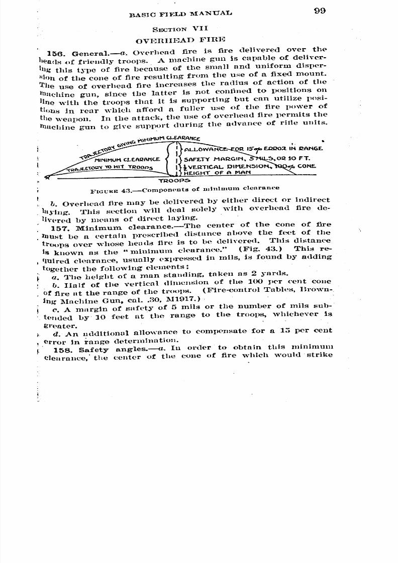
8/22/2019 Basic Field Manual Volume III-1932
http://slidepdf.com/reader/full/basic-field-manual-volume-iii-1932 104/203
f
BASIC FIELD MANUAL
SECTION VII
99
OVERHEAD FIHl~
156. General.-a. Overhead fire is fire delivered over the
heac}:'! of friendly troops. A machine gun is capable of deliver-
Ing this tnle of fire because of the small and uniform disper-
Io;10n of the cone of fire resulting from the use of a fixed mount.
The use of overhead fire increases the radius of action of the
machine gun, since the latter is not confined to positions on
line with the troops that it Is supporting but can utilize posi-
tiollS
in rear which afford a fuller use of the fire pO\ver of
the weapon. In the attack, the use of overhead fire permits the
machine gun to give support during the advance of rifte units.
FIGURE 4:3.-Componpnts of minimum clearance
b. Overhead fire may be delivered by either direct or indirect
lll~'fng. This section will deal solely with OYerbead fire de-
, livpred by means of direct laying.
157. Minimum clearance.-The center of the cone of fire,lnUlo;tbe a certain prescribed distanee above the feet of the
troops over whose lletHls tire is to he delh"ered. This distanee
Iii known as the" minimum dearanee." (Fig. 43.) This re-
, fIUired cll~aranee, usually expressed in mils, is found by adding
together the following elements:a. The height of a man standing, taken as 2 ~"ards.
1J. Half of the vertical dimension of the 100 per cent coneot fire lit the range of the tl.oops. (l~ire-eontrol Tables, Brown.
Jng 1\Iachine Gun, caI. .BO, 1\11917.).
c. A margin of safety of 5 mils or the number of mils sub-t<mded by 10 feet at the range to the troops, whichever Is
gl'eater.d. An nddit10nal allowance to compensate for a 15 per cent
,error in range tleterminntion.158. Safety angles.-a. III ol'ller to obtain this minimum
Clearance,' the center of the cone of fire which would strike

8/22/2019 Basic Field Manual Volume III-1932
http://slidepdf.com/reader/full/basic-field-manual-volume-iii-1932 105/203
100BASIC FIELD MANUAL
the feet of friendly troops would have to be elevated throngb
nn angle equal to the minimum clearance expressed in mils.
This required angle is known as the "saft'ty angle." rflle
~afet~. nngle for <lir'eet IUJ"ingis thus seen to be the difference
between the angle of elevution required to ohtain the minimunr
clearance, and the angle of elevation requiI;ed to hit the feet ofthe troo))s.
b. The safet~. angles for all ranges on level or uniformlY
sloving ground have been computed and are contained in r"ire-
('ontrol Tables for Browning Machine Gun, caliber .ao, modelof 1911.
FIGURE 44.-Application of gunner's rull~
c. To Jl('rmit overlwad tire on any target, the cone of tire.
must pass over the hl'ads of friendly troops by at least theminimum deurance. In order to have a quick and simple l
means of insuring this condition, two rules of thumb huve
been devised by means of whieh sufety angles may be meas-
urcd with thc rear sight. Th""c rulcs arc ""rrcct only for jthe :\IH)OG ammunition (15O-grain bUllet). ,
159. Gunner's ntle.-Tlle gunner's rUle is designed for use
in ('a~e the range to the target is equal to or less than 900..;
~'ards. It Is ar1plied by the gunner unless the sufety
has been detel11l1ned un!l announced by the section or platoon
leader. The rule is as follows (fig. 44) :
a. Lay the gun on the target with the correct sight settingto hit the target.
b. 'Vithout changIng the laYing of the gun, set the rearsight at 1,525 yards. .,
o. Look through the sights and note the point where thisnew line of sighting strikes the ground.
limit-
,
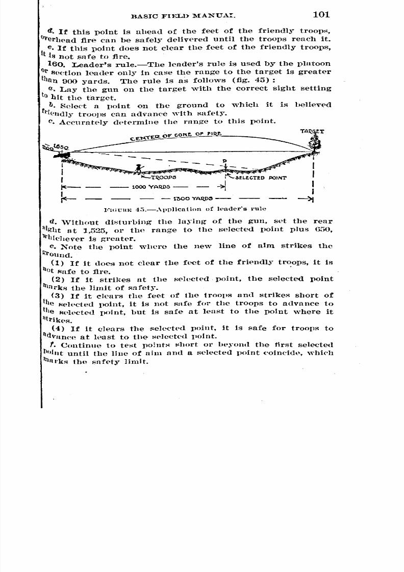
8/22/2019 Basic Field Manual Volume III-1932
http://slidepdf.com/reader/full/basic-field-manual-volume-iii-1932 106/203
BASIC FIELD MANUAI. 101
d. If this point is ahead of the feet of the friendly troops,
O"erhead fire can be safely delivered until the troops reach it.
e. If this point does not clear the feet of the friendly troops,
It is not safe to fire.160. Leader's rule.-The leader's rule is used by the platoon
orSett!on leader only in case the range to the target is greater
than 900 yards. The rule is as follows (fig. 45) :
a.• Lay the gun on the target with the correct sight setting
to hit the target.
b. Select a point on the ground to which it is believed
f1'1(llldlyroops cnn advance with safet~'.c. Accurately dptermine the range to this point.
I
II~-
'--TQ.OO,P5
1000 YAIU)5
1~OOYAR.D::l--
FiGUllE 4;'i,-Applicution of h'uder's l'ule
d. 'Vithout disturbing the laying of the gun, set the rear
~Ight at 1,525, or the range to the selected point plus 650,\\'hlchever is greater.
c. Note the point where the new line of aim strikes the
~rOuIld.
(1) If it does not clear the feet of the friendly troops, it is
!lotFlafe to fire.
(2) If it strikes at the selected. point, the selected point
Illal'ks the limit of safety.(3) If it clears the feet of the troops and strikes short of
the Flelpcted point, it is 110t safe for the troops to advance to
the Flelected point, but is safe at least to the point where it
~tl'lk('s.
(4) If it clears theseleeted point, it is safe for troops to
lld\'ltIleeat h~ust to the select(~d point.
f. Continue to test points I'(hort or beyond the first selected1l01lltuntil the line of aim and a selected point ('oinelde, which
1ll11I'ks the saf{'ty limit.
~
-- -
-- -- - -- -~
'

8/22/2019 Basic Field Manual Volume III-1932
http://slidepdf.com/reader/full/basic-field-manual-volume-iii-1932 107/203
102 BASIC FIELD :MANUAL
161. Procedure before friendly troops reach limit
safety.-a. Safety limit identified on the ground.-The safe
limit having been determined, the gunners and all leaders
note some terrain feature by means of which the limit mayidentified on the ground. In case safety has been determined 11
the platoon or seetion leader, the limit of safety is announC
so that the gunners and squad leaders are able to identl
it; if ncel'ssary, the limit is indicated with the rear gig
of each gun, being careful not to change its laying on ttarget.
b. Report by gunners.-In case tbe gunner's rule is appliegunners r{>port "clear" or "not clear" to indicate whether
is safe to fire.
c. Checking laying 'while firing.-After determining or noti
the safety limit, the gunner runs the sight back to the ran
to the target in order, while firing, to check the laying <?nttarget.
162. Procedure after friendly troops reach limitsafety.-a. Unless otherwise ordered, when the fr.iendly troo
reach the limit of safety, gunners cease firing.
b. If it is desired to search the area in rear of the target, t
section or platoon leader announees a new range and orde
Search the rear area. The range announceu is 1,525, or the raIl
to the target plus 650 ~'ul'tl:,;,whichever is greater. Gunnel
set their sights at the range annoulleed, and, keeping tlJline of sighting ahead of tile feet of the friendly troops, elevll
their guns by a series of 2-mil lifts until their sights are
on the target. In case the friendly troolls can not be seen, tgun is lifted at once to the target with the sight setting
. llounced.' Each gun covers the same front it covered
firing 011 the target. The medium or slow rate of fire
be used to ('onserve ammunition. 'Vhen the friendlyreach the target, gunners ('ease firing. .,
163. Use of :field glass in applying safety rules.-It
frequently desirable to determine safety for overhead
before guns are placed in position. Safety may be appro
mately determined by means of. the inverted sight leaf in
t~'pe EE field glass. After the guns are emplaced, safe
f;hould be checked, where Ilossible, with the gun sight
(Pto Two, eh. 1, Sec. III.)
,
n1\l
allgne
a
wllt
sho\1
troo
:t
t
'

8/22/2019 Basic Field Manual Volume III-1932
http://slidepdf.com/reader/full/basic-field-manual-volume-iii-1932 108/203
BASIC FIELD MANUAL 103
164. Troop safety zones.-lt may at times be imperative to
deliver overhead fire, if actual safety does exist, even though
the gunner's or the leauer's rule inuicates that it is not safe
to fire. Such conditions will usually obtain only when the
target is at a long range, and the guns, troops, and targets are
at about the same elevation. To cover such cases, the following
table of troop safety zones for the 1\11906ammunition (150-
grain bullet) has been worked out. It will always be safe to
deliver overheuu fire by direct laying at the ranges indicated
it the troops are within the limits shown, unless, of course,
they are above the line gun-target, when it will not be possi-ble to use uirect laying. .All ranges must, however, be accu-
rately determined.
:Range to target (~1arus): Troopsare safe from-1,400________________________________ 500 to 600 yards.1,mO_______________________________ 325 to 825 ~'arus.
1,600 .. 275 to 9GOyarus.
1,700________________________________ 225 to 1,100 ~'ards.
1, 800_ _ _ _ _ _ _ _ _ _ _ _ _ _ _ _ _ _ _ _ _ _ _ _ _ _ _ _ _ _ _ _ 200 to 1, 200 yards.
1,900________________________________ 175 t,o 1,325 y~rds.2,000 150 to 1, 425 yards.
! 165. Precautions for overhead fire.-The following precau-
tions will always be observed when overhead fire is used: .
a. If safety has been checkeu only by application of theleader's or. gunner's rule, overhead fire will not be delivered if
the'troops are less than 300 or more than 1,800 ~'ards from the
guns, unless the vertical interval of the troops below the line
gUn-target Is sueh as to make safety obvious.
b. A barrel that has fired 5,000 rounds or which gives evi-
dence of excessive muzzle blast should not be used for overhead
fire.c. The tripod must be firmly mounted and wherever prac-
ticable should be snndbagged; badly worn tripods will not be
Ul'led.
d. The water jaeket must l,e kept filleu, anu guns not allowed
to heat excessively. .
c. Depression stops should be used to prevent the muzzle
of the gun from being accidentally lowered below the limit of.Flnfety; the neecssities of battle, llowever, may prevent the u~e
of this precaution.
-
-

8/22/2019 Basic Field Manual Volume III-1932
http://slidepdf.com/reader/full/basic-field-manual-volume-iii-1932 109/203
104 BASIC FIELD MANUAL
f. Overhead fire must not be delivered through woods whichare likely to deflect bullets into friendly troops.
g. Friendly troops should be informed when fire is to be
directed over them.SECTION VIII
l<~IX.AL PHOTECTIVE LIXES AND SI~JCTOUS Ol<"' FLUE
166. Definition of final protective line.-The final protective
line of a machine gun may be defined as a predetermined linf'
nlong whith, in order to stop assault.'?, it is intendcr]; to place
graZing fire, fixed a."! to direction ana elevation, and capa7J7cof(ldivenl under anycondifion.fJ of '/.;..;,sibility.
167. Sectors of fire.-Front-line machine guns on the de-
f{'IIl;;iveare assigned sectors of fire, the inner limits of wIlich
are usually, but not always, the bands of grazing fire delivered
along the final protective lines. 'fhe machine-gun fire unit is
re~ponsible for engaging the enemy within its sector, subject.
in~ him to fire as he approaches, and finally forcing him topass through coordinated bands of grazing fire before he canueliver his assault.
168. Influence of terrain.-On level or uniformly sloping
ground up to a range of 700 yards the lower part of the com'
does not rise above the height of a man standing at any point
'from the muzzle of the gUll to tIle point of ll11IJllct. The length
()f the farther half of the beaten zone should be added to therange, 700 ~'ards, making the total possible danger space, on
level or uniformly sloping ground, apvroximately 775 ya'rds.
(These figures are for the 150-grain bullet, l\IWOG ammunition.)
The great length of the danger space on such terrain is the
most imllortant characteristic of machine-gun fire with refer-
ence to the final vrotective line. However, ground that slopes
uniforml)' for 700 ~'ards or level stretches of that .length are not
often found. Three cases are given in the following para-
graph to illustrate the different types of terrain on which final
pl'ote(.tive lines ma)' have to be placed and the methods of
laying the gun for elevation and direction in order to get the
maximum alllount of grazing fil'e in each case.
169. Methods of laying on final protective lines.-a. Lay
tlte gun for direction by sillJ{llysighting in tlte desired direction.
b. Obtain proper elemtion ns follows:
(1) Case 1.-1t tlte ground is level or slopes uniformly for
a distance of 700 ~'ards from the gun, select a point at a range

8/22/2019 Basic Field Manual Volume III-1932
http://slidepdf.com/reader/full/basic-field-manual-volume-iii-1932 110/203
BASIC FIELD :MANUAL 105
of approximately 700 ~oarodsand, with a sight-setting of 700
3°ards, aim at this point.(2) Case 2.-If the ground slopes uniformly for a distanee
less than 700 yards, select an aiming point, such as a bush,at any range along the slope. Aim at a point on the object
about the height of the gun, using a sight setting of 700 ~oanls.
The fire will be grazing only as far as the break in uniform
8lope.(3) Case S.-It is possible to place grazing fire on the re-
'Verseslope of the hill if the shape of the ground approximates
the curve of the>trajectory at the range to the slope. If it isdesired to place a final protective line on such a slope, lay
the gun on the crest with a sight setting to hit the crest, and
tlwn elevate the gun three mils, in order to clear the hill with
the lower half of the cone. For the average ranges used in
final protective lines fire-control tables show that 3 mils will
Usually cause the lower half of the cone to clear.
c. Whenever the tactical situation permits the laying should
lie verified by firing.it. If a depression exists between the gun and the ground
On which the final protective line is placed, the depression is
dead space in the band of machine-gun fire, and must be cov-
ered by other weapons.170. Laying gun at night and during fog or darkness.-a.
The gun having lwen laid by any of the foregoing methodsof direct laring, provision must be made to enable the squad
to lay the piece when under a sereen of darkness, smoke, or
fog. The following simple and efficient methods are avail-
able, data by both of which should be obtained and recorded:
(1) First method.-The gun having been properly laid for
direction and elevation, zero the dial, clamp it, and then
Jlleasure the quadrant elevation-that is, the angle above thehorizontal-with a clinometer. Thereafter, to lay the gun at
any time, turn the gun until the index on the pintle is op-
llosite the zero mark on th(>.traversing dial and b~' means of
n clinometer set the recorded quadrant elevation on the gun.
(2) Second, method.-The gun having been properly laid
for elevation and direction, place an aiming stake at a short
distance in front, but offset slightly from the line of fire.Without disturbing the laying, manipulate the rear sight until
a line of sighting is obtained on a designated mark on the
{)8!)!):l°-32--8

8/22/2019 Basic Field Manual Volume III-1932
http://slidepdf.com/reader/full/basic-field-manual-volume-iii-1932 111/203
l OGBASIC FIELD :MANUAL
aiming stake. To lay the gun properly at any t~me, set the
sights according to the readings prpviously recorded and aim
at the mark on the aiming stake. This method is less aC'
curate than the first, but enables fire to be delivered in casethe clinometer is lost or broken.
b. The determination and application of data by these meth'
ods are essentially indirect laying and are included here uecause
of its close connection with direct laying.
171. Procedure in firing.-a. Rate of {ire.-The normal rate
of :fire on a final protective line will be "rapid" (250 rounds
per minute). Successful protection of a position will dependto a great extent upon the intensity of fire. 'Vhen the two
guns of a section are assigned the same final protective line,
the section leader must so coordinate the fire that the maxi-
mum usable rate is obtained and at least one gun is alwaysfiring.
b. Type of {ire.-li"lxed fire will be used along a final protec-
tive line. This will insure dense and continuous fire. Gunnersmust be taught that once fire has been ovened on a final protec-
tive line, their mission Is to keep as great and as nearly a con-
tinuous stream of fire on that line as possible; any deviation
will result In uncoveling a portion of the line, and the enemy
assault may pass through this gap without sustaining losses.
ThIs rapid tixl'd fire is maintained until the assault has been
repulsed or the position has fallen. Guns are then shiftedto the most dangerous target.
SIWTION IX
nANGE CARnS
172. Defense range cards.-a. General.-(l) In order to be
prepared, on the defensive, to deliver fire promptly, firing data
should be determined to all key points, such as crossroads,
ridges, stream junctions, woods, and other landmarks within
the sectors of fire at, or near Which, targets are likely to
appear. These data must be recorded, to serve as a guide to
the gunners and section leader.. A range card for each gun
is used for this purpose. It Is usuaily in the form of a sketch
of the sector, shOWing only the probable locations of targets
and the data as to direction and range, or elevation, necessaryto plnce fire on these points.
8/22/2019 Basic Field Manual Volume III-1932
http://slidepdf.com/reader/full/basic-field-manual-volume-iii-1932 112/203
BASIC FIELD MANUAL 107
(2) The employment of range cards allows decentralization
()f command without loss of fire control. This advantage is
especially evident in highly organized defensive positions where
guns may be widely separated. Range cards are also of great
'Value in planning the cpordination of defensive fires. Dupli-
cates of the original range cards prepared during the occupa-
tion or consolidation of a newly occupied position are collected
by platoon leaders, who consolidate them for their units.
With the addition of such brief explanatory remarks as may
be necessary, these reports are sent back to the company com-
lnander. Such reports show exactly what the guns can do and
In(licate :where coordination and rearrangement are necessary.
b. I'rclJaration of.-(l) Hange cards should be prepared im-
lllediately upon occupation of defensive positions and copies
Sent to the next higher commander. The defense cards form
a record for the use of relieving gun teams, and are alwa)'s con-
sillered as part of the orders for a position. Range cards
sllould be prepared in advance for nIl' positions, including
alternate and supplementarY positions.(2) In preparing range cards, the following should be taken
us guides: .,
(a) Notation should be made of the accurate location of the
gun posidon, and the position named or numbered.
(b) A means of orienting the card, either by magnetic north
or by reference to prominent terrain features, should be
provided. . ,
(c) All data allli instructions ~hould be legibly printed.
(eZ) Landmarks or targets should be indicated by conventional
signs or sketches in perspective, naming them where necessary
to prevent misunderstanding. .' ~.
(e) Targets should be numbered from right to left.
(f) The final protective line, which usually forms one limitof the sector of fire, should be taken as a base line, with it dialsetting of .zero. That part of the line which provides fixed
grazing fire should be shown in heavy black.
(g) The directions to all targets should be indicated by the
proper dial settings and the elevations by the proper sight
settings and quadrant elevations. (See (3) below.)
. (3) Whenever possible~ Indirect laying data should be pre-pared for all guns, even though they are sited primarily for
direct la~'lng. These data determine the direction to the points
"
'

8/22/2019 Basic Field Manual Volume III-1932
http://slidepdf.com/reader/full/basic-field-manual-volume-iii-1932 113/203
108BASIC FIELD MANUAL
selected as probable locations for targets, and the correspond-
ing quadrant angles of elevation; that is, the angles of eleva-
tion above or below the horizontal. Paragraph 170 outlineS
the proc('dure required to establish a gun on its final protectiveline under any conditions of Visibility. l\Ietlwds exactly sim-
ilar to tho:-;e given therein may be employed in securing the
data required for all key points in the sector of fire. The fiual
PI'otN:tive line should be taken as a base line to which the direc'
tions of nIl other targets are referred. 'Vitll the gun estab-
FIGl"RE 46.-Range card No.4 gun; 2d Sec., Co. D, 1st Inf.
Jislwd on its final protective line, the dial is zero~d. The gun
is then laid successively to hit the points selected as probable
targets; for each point the dial reading and the quadrant angle
of elt'vntion are recorded on the range card. If the target l1US
width the dial settings for both flanks are recorded. There-
aftN', if it is desired to fire on any of these poInts, the dial reud-
Ing um} the quadrant angle of elevation are announced asfollows: "Dial 5,820, QJ~ Vlus 58" or, If range cards have been
prf'vured, fire is ordered by simply announcing the targetnumlwr.

8/22/2019 Basic Field Manual Volume III-1932
http://slidepdf.com/reader/full/basic-field-manual-volume-iii-1932 114/203
BASIC FIELD :MANUAL 109
(4) Figure 46 1S an example of a simple type of range card
)1' Use in defense. Such cards may he prepared immediately
FIGURE 47.-Range card No.2 gun; 1st Sec., Co. D, 1st Inf.
Ifter the occupation of a position. They are replaced as soon
Is possible by others similar to that shown in Figure 47, which
~i\'l~S the data for both direct and indirect laying.
1400 0
1100 300
700 700
100
o 1400
\~~,~ rAl(NH'tOU5f'
. ~~.-::'
INITIAl.. GU/'(P051T10J \tOOYA~M~T Of )10USf.ON D~ey RI~~
FIGURE 48.-Type of attack range card
173. Attack range cards.-No fixed form of attack range
card is prescribed. Figure 48 shows a suitable tn>e. The
rallges are measured from the initial gun position, using a
rUllge finder or map wherever possible. The range card en-

8/22/2019 Basic Field Manual Volume III-1932
http://slidepdf.com/reader/full/basic-field-manual-volume-iii-1932 115/203
110BASIC :nELD MANUAL
abIes the gunner or section leader to determine quickly tl1
range to the enemy position, at any time during the advanC
by interpolating between the measured ranges to the ke.
points. It is Usually not necessary to indicate directions 0
quadrant angles of elevation on an attack card.
SECTION X
FIRE CONTHOL
174. General.-a. Fire control of machine guns Implies tb
ability of the leader to open fire at the Instant he
adjust the fire of Ills guns Upon the target, shift it from
target to another, regulate its rate, and cease firing at will.
He must be able to do all of these things pI'omptly if tbe
fire is to be E'ffective. Lack of proper fire control results
loss of surllrise effect, premature disclosure of position" miS'
application of fire on unimportant targets, loss of time i~
securing adjustment, and wastage of ammunition. Fire coil'
trol is then-fore a bighly important phase in the techniqueof direct laying. ,
b. }~ire control is based primarily on diSCipline, and second'
arily on correct technical training. Inasmuch as machine-gUll
Sl.'Ctions are fr~'quently S<,parated by Wide intervals, control
must often be decentralized .. To this difficulty are added the
excitement and noise inCident to firing an automatic' weapol1.
Under th('se conditions goot! fire control can be had only if allmen are WE'lldisciplined and llave the proper technical trainingto carry out fire orders promptly.
175. Chain of fire control.-a. The company commander
gives his ord('rs orally directly to the platoon leaders or trans'
mits written orders to them by messengers. These are tacticnl
orders which rarely prescribe the tecllllique to be employed in
('arr~'ing them out. The actual control of fire' is thus left tothe platoon leaders. As a rUle, the latter give their instructionS
orally directly to the section leaders. Section leaders may be
:ts8embl~d, under Cover, for this purpose, or the platoon leader
may go successively to the section leaders and give them im]i.
vidual orders. If the sections are Widely separated, as theY
may be in the defense, it may be necessary for the platoon
leader to send written instructions to section leaders.' IIe willrarely be able to issue orders orally to hi~ entire platoon oncefire has h{,(,ll-oppnf'd.
desirc~!
oll
i

8/22/2019 Basic Field Manual Volume III-1932
http://slidepdf.com/reader/full/basic-field-manual-volume-iii-1932 116/203
BASIC FIF..LD :MANUAL 111
, b. Section leaders use similar methods in controlling theIr
~qt1UdS. They should post themselves in positions from which
hey can observe the fire and where they can be seen by the
o.2 at each gun. Before fire opens their orders will as a rulee oral. While firing is going on, signals (alone or combined
IVithoral orders) will usually have to be used for the control
ot fire. It will frequently be necessary for the leader of
a section to go to the guns and give orders directly to the gun-Iers. This method is especially applicable wben new and
lnexpected targets appear after tbe unit is engaged.
o. Witbin the gun squad, the squad leader is responsible fornre control. When ordered to do so by the platoon or section
euder the corporal fires the gun. This will often saye time in
the transmittal of orders for the occupation of a position and in
the designation of indistinct or poorly defined targets, and in
~(~mecases will give greater assurance of effective fire. The
cO/'poral may fire whenever, in his opinion, it is necessary
to do so in order to bring effective fire speedily on the target.\\"henthe corporal does fire No.1 assists him in the observation
flnd adjustment of fire and No. 4 becomes responsible for
l\mmunition supply. When not firing the corporal posts himself
~oas to be able to observe the fire of the gun and at the same
time close enough thereto so that he can shout his orders to
the gunner. The corporal does not look to the rear for signals,
but concentratps on the observation and adjustment of fire.Observation and adjustment of fire on the proper target is the
ltJost important fire-control duty of the squad leader. It isthe duty o'f No.2 to watch the section leader for signals; he
can not do this if be observes the fire. Ill' transmits all orders
to the gunner or the squad leader.
176. Adjustment of :fire.-a. Observation and adjustment of
6re Is the most important phase of fire control. Itmust beeOntlnuous throughout the action. The gunner must be trained
to observe and correct his own fire without command and to
('heCkhis laying from time to time. Ill' should also be in-
fitructed to anticipate the action of the enpmy after fire is
0PNletl, shifting his fire to cover any changes in the formation
Or location of his target. If he fails to do these things, the
Qqundleader must check him and this responsibility continues11D through the platoon leader.
b. Corrections are announced or signaled as "Up," "Down,"
"IUght," or "Left" so many mils. Small changes in elevation.

8/22/2019 Basic Field Manual Volume III-1932
http://slidepdf.com/reader/full/basic-field-manual-volume-iii-1932 117/203
112BASIC FIELD MANUAL
such as Up 5," or Right 2," are set off on the elevating haJJ
wheel or the windage scale. Large range corrections are ml1l1
by announcing or signaling a new range. Signals are prescribe
in Basic F'ield Manual, Volume II.c. 1Vl!ere it is not Possible to get observation of strike, trace
ammunition may be used in the ratio of 1 tracer to 10 balls.
SECTION XI
:FIRI'] ORDERS
177. Purpose.-A machine-gun leader, 11aving made a
decision to fire on a target from a certain position, conve~'s tblS
information to his subordinates in a combat order. In
to the tactical setting and decision, however, 1ih~ leader must
give certain technical instructions as to how the target is tit
he engaged. These technical data may be included in the
bat order of the leader, in which case they correspond to part
of paragraph 3, or they may be given subsequent to the issuance
ef the. comhat order. In either case the technical data by whic!J
the fire of the section or platoon is c011tro11e(1orm the fire order.
178. Basic elements of fire order.-A fire order contaiJJs
three basic elements, which are announced or implied in everS
case. Only such parts of these will be included as are essential,
but the sequence must alwa~'s he as follows:
Target-designation element.
Fire-distribution element.Fire-control element.
G. Target-desigltfltimll elcrnent.-(l) The target-designntioJ1
element implies ability on the part of the leader to point out tbl'
target in such a manner that gunners ('IU l pick it up readilY,
The leader may lay one or both guns, fire a burst from one of
the guns, or give an oral description.
(2) An oral descrirltion consists of an announcement of tIlt'
range, the direction, and a description of the target, where nee'
l'ssary. For example, the target-designation element would beas follows:
(a) Hange noo.(1) To your right front.
(c) Enemy skirmish Ifne.
fl. Fire-di,sfribufion, elcment.-The fire-diiitrihutionincludes the subdivision of the target, if necessary, and the type
of distribution. :For example: A IJlatoon leader desires to crosS
" "
tactiCO
o.t1ditiol
coUl
elf'l}}(}

8/22/2019 Basic Field Manual Volume III-1932
http://slidepdf.com/reader/full/basic-field-manual-volume-iii-1932 118/203
BASIC FIELD l\IAXUAL 113
Ie fire of his sections on a frontal target, using the scissors
lethod; the distribution element of his order would be as
)llows:
(1) 1st section, left.
(2) 2d section, right.
(3) Scissors.
o. Fire-control element.-The fire-eontrol element may
\~lUde-
aute of fir~.
l'irne of opening fire.
COlumandor signal to commence firing and cease firing.(1) Rate of {ire.-The following are the prescribed rates of
re; unless otherwise specified, the rapid rate will be used.
Slow, one-quarter box per minute (GO rounds).
h1Pdium,one-half box per minute (125 rounds).
!tUIlid,one box 'per minute (250 rounds).
(2) rime of opening fire.-( a) It is often of great importanee
~I.tmachine-gun fire be withheld until the proper moment to~eUremaximum effect and that all guns open at the same
l~tunt. The greatest surprise and shock effect are thus ob-
lined. To insure this condition, the leader may preface the
0tnrnand or signal for commencing fire by the words "At my
Ignat This permits him to check all guns to see that they
re properly laid, or, in case of overhead fire, that there is
tn('i(~ntclearance, and enables him to hold the fire until the
lticalmoment.
(b) Oommanl1 or 8ignal.-lf fire is to be opened immediately,
ne command At my signal is omittell, and Commence firing is
nOUllcedimmediately after the other elements of the order.
Unnel'sopen fire individually as soon as laid.
179. Examples of fire orders-a. Many fire orders will con-
I~tof only the simplest expression of the three basic elements,r one ()r more elements may be omitted. Examples are given
elow:
l]J:urnple 1:
Range 900.
3T-mm. gun.
Commence firing.
FJ;ranlple 2:
Range 1,000.
Commence firing.
"
8/22/2019 Basic Field Manual Volume III-1932
http://slidepdf.com/reader/full/basic-field-manual-volume-iii-1932 119/203
114 BASIC FIELD MANUAL
b. In case separate missions are assigned individual gO
or sections, the order may be as follows:
"No.1 (or first section)-900.
Near end.
No.2 (or second section)-1,100.Far end.
Inward traverse and search.
Commence firing.
c. An order callIng for overhead fire may be in one of t
following forms:
(1) It the range is less than 900 yards-Range 850.
To your left front.
Crest of small knoll.
Scissors.
Overhead.
At my signal.
Commence firing.(2) If the range Is greater than 900 yards-
Range 1,200.
To your front.
Target, edge of woods.
Inward traverse.
Overhead.
Friendly troops in the draw to the front.Safety limit that line of scrub brush [pointing].At my signal.
Commence firing.
(3) If It is desired to search the area in rear of the tar
after the troops "have reached the limit of safety, an order
thIs form may be used:
Suspend firing.1,850.
Search the rear area.Slow.
Commence firing.
d. In case fire for adjustment is used, the order may befollows:
No. 1-900.Sight right 3.
Point where road enters woods

8/22/2019 Basic Field Manual Volume III-1932
http://slidepdf.com/reader/full/basic-field-manual-volume-iii-1932 120/203
BASIC FIELD MANUAL
Adjust.
Commence firing.
115
All guns-975.
Edge of woods.
Inward traverse.
Commence firing .
. e. WHen firing with combined sights, the difference ln range
~ay be applied by individual guns or by section, as follows:
l!JJ)(lmple 1:
Combined sights.
No.1, 1,000.
No.2, 1,100.
No.3, 1,200.
No.4, 1,300.
To you;' right front.
Target, large clump of bushes.
At my signal.
Commence firing.
1iJJ)a.mple 2:
Combined sights.
First section, 1,250.
Second section, 1,350.
Enemy column.
At my signal.
Commence firing.
1. A small area in the vicinity of a given point may be
~eredas follows:
Range 1,200.
To your left front.
On slope of hill.
Lone scrub pine [pointing].
Traverse 12.
Search 4.
Medium.
Commence firing.
fJ . An especially difficult target may call for a lengthy order
IllliIl1rto the following:
Range 1,100.Sight left 6.
To your right front.
8/22/2019 Basic Field Manual Volume III-1932
http://slidepdf.com/reader/full/basic-field-manual-volume-iii-1932 121/203
I l G BASIC }'IELD MANUAL
Reference-lone pine.
To the left-small scrub oak.
Left 20 mils and beyond.
Corner of ditch.
Enemy machine gun.
Traverse 8.
Search up 4.
Commence firing.
S~:CTION XII
DIHECT LAYING pnOnLI~MS
180. Purpose and scope.-Direct laying problems are techJ1i
cal exercises designed to instruct officers amI mf'n of mnchill
gun units in the application of the technical methods of <lirer
la~'ing under simple tactical situations. No tactical
are required in these exercises, and the tactical s(.tting shoU l1
be nothing more than a background for the demand for IlIII
chine-gun fire on a given target. The requirement may \'
simply the fire order, or the fire order and actions of the ullil
either with or without actual firing.
181. Preliminary instruction.-Preliminary instruf'tion J}l~'
be given with the situation pre:-;ented by means of a blac~
board sketch, a chart, or a landscape target. Each proble11
should be carefully explained, and a reasonable time alloWel
for its consideration. The required fire order, and, where tl
propriate, a statement of the actions of leaders and gunne:
should then be demanded. The manller of delivery of tb
order as well as its correctness should be noted and commente
upon. All leaders. are thus taught to deliver fire orders wit
confidence, in a sufficiently loud tone of voice, and with dell
ness and brevity.
182. Examples of fire-order problems.-a. Pro1Jlern No.1.
(1) Situation.-A machine-gun section on outpost duty 0
serves a patrol of four 1I1enat A. About 150 ~'ards in its rell
are two columns of files of 10 men each on the two sides
the road. The columns are partly protected by the stone Wtll
The point is signaled to turn right at the road junction. segeant n, commanding the machine-gun section, decides to egage the advance party.(2) Requirement.-The fire order.
'
<1ech;io
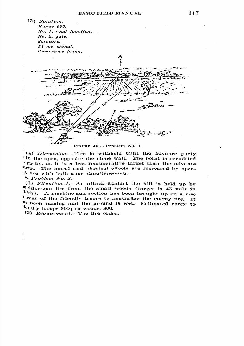
8/22/2019 Basic Field Manual Volume III-1932
http://slidepdf.com/reader/full/basic-field-manual-volume-iii-1932 122/203
BASIC FIELD :MANUAL
(3) Solution.
Range 500.
No. I, road junction.
No.2, gate.
Scissors.
At my signal.
Commence firing.
1
117
(4) DiHcIl8Hion.-Fire is withheld until the advance party
in the opeIl, opposite the stone wall. The point is permitted
go by, as it is a less remunerative target than the advance
11h'ty. The moral and physical effects are increased by open-
~l;" fire with both guns simultaneously.b. Problem NQ. 2.
(1) Situation I.-An attack against the hill is held up by
aChine-gun fire from the small WOOds (target is 45 mils in
'1(llh). A machine-gun section has been brought up on a rise
I l'Pur of the friendly troops to neutralize the enemy fire. It
ll~ I)(>enraining and the ground is wet. Estimated range to
'Iendly troops 300; to woods, 800.(2) Rcquircment.-The tire order.

8/22/2019 Basic Field Manual Volume III-1932
http://slidepdf.com/reader/full/basic-field-manual-volume-iii-1932 123/203
118 BASIC l"IELD :MANUAL
(3) Solution.
No.1,' range 800. or
Point where road disap-
pears.
Adjust.
Overhead.
Commence firing.
----------------------
All guns-850.
To your right front.
Edge of woods.
Scissors.
Overhead.
At my signal.
Commence firing.
No.1, range 800.
No. 2, 850.
To your right front.
Target, edge of woods.
Scissors.
Overhead.
At my signal.
Commence firing.
takes PO't
Sl~C01l0
FIG {iRE GO.-Problem No. 2
(4) Situation II.-The second section arrives find
sitlon on the left of the first.
(5) Requirem~nt.-The fire order;
(6). Solution.-l\!essage by runner to leader of thesection:
No.3, range 800.
No. 4,850.To your right front.
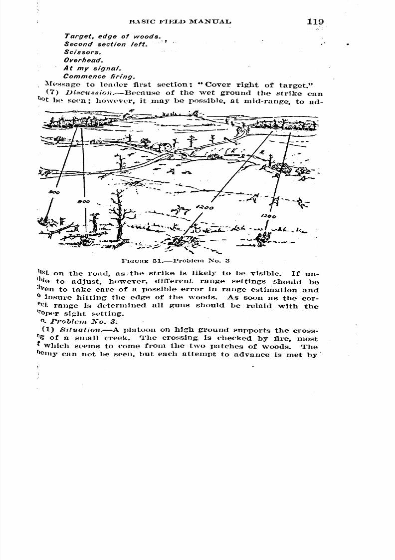
8/22/2019 Basic Field Manual Volume III-1932
http://slidepdf.com/reader/full/basic-field-manual-volume-iii-1932 124/203
RASIC }'IELD MANUAL 119
Target, edge of woods.
Second section left.
Scissors.
Overhead.
At my signal.
Commence firing.
l\{(>ssage to leader first section: "Cover rigl1t of target."
(7) Di8CU88ioll.-Because of the wet ground the strike can
~ot UP seen; hmwver, it may be possible, at mid-range, to ad-
/ goo
~.l~~...FIGURE 51.-Pro1Jlem No. 3
"~
Il!iton the ruad, as the strike is likely to be Visible. If un-
lble to adjust, however, different range settings should be:l\>ento take care of a possible error in range estimation and
()insure hitting the edge of the woods. As soon as the cor-
eet range is determined all guns should be relaid with the
11'0{X'r sight setting.
o. Problem ]1;0. 3.
(1) Situathm.-A platoon on high ground supports the cross-
ng or a slllall creek. The crossing, is checked by fire, mostt Which seems to come from the two patches of woods. The
elllYcan not be s£'en, but each attempt to advance is met by.
"
~

8/22/2019 Basic Field Manual Volume III-1932
http://slidepdf.com/reader/full/basic-field-manual-volume-iii-1932 125/203
120 BASIC FIELD MANUAL
Second section.
900.
To your left front.
Woods.
Scissors.
Overhead.
Friendly troops in small
At my signal.
Commence firing.
and
heavy fire. Range to left woods 900; to right woods
The right woods subtends 75 mils and the left woods 50 IT
(2) Rcquirement.-The fire order.
(3) Solution.
First section
1,200.
To your front.
Woods.
Inward traverse.
Overhead.
Friendly troops on far
bank of creek.
Safety limit: Line running
through road junction.
Commence firing.
(4) Di8cu8Bion.-Visible targets are not to be expected aga
an organized area. Leaders must engage the areas wllich S
to give the enemy the most cover and the best positions.
effectiveness of their fire must be judged br the actions of
enemy. In this situation the fire of the two sectiolls m
be crossed in order to obtain oblique fire.
d. PrOblem NO.4.
(1) Situation.-The battalion is held up by fire from
woods to the front. A section is working up the ravine to
left to flank the woods. The machine-f.,'1lllplatoon
the company has taken position on high ground. 'Woods
ure about 65 mils. The runge to the woods antI the ridge 1s
and to nearest troops 350 yards.
(2) Rcquircment.-The fire order.
(3) Solution.
Range 700.
To your front.Woods.
First section:
Front edge of wood,.
Inward traverse.
Second section:
Left edge of woods.
Fix.Overhead.
At my signal.
Commence firing.
er
1,
suppor m

8/22/2019 Basic Field Manual Volume III-1932
http://slidepdf.com/reader/full/basic-field-manual-volume-iii-1932 126/203
i
BASIC FIELD :MAN VAL 121
(4) Discu8sion.-The parts of the woods from which the
emy may bring fire must be neutralized so as to further the
Vance. In this case, fire must be heavy on the front and
ft. Since the front of the woods subtends more than 50 mils,
ward traverse must be employed against this part of the tar-
(It. Fixed or searching fire may be used on the left edge of
e woods, as this portion of the woods will be enfiladed.
FIGL'ltE 1'i2.-rl'oblcm No.4
SI';CT10N XIII
IRECT LAYING ON LANDSCAPI~ TARGETS AT 1,000
INCHES
183. General.-Most phases of the technique of direct laying,
'ueh as fire distribution, overhead fire, target designation, fire
ontrol, and fire orders, may be taught on landscape targets.
The use of landscape targets makes possible the teaching of
direct laying indoors where conditions are unfavorable for
outdoor work. Instruction may be had with or without ball
allllllunition. 'Vhen ball ammunition is used it permits the
~'11Jlllerso see the results of their firing with a small expendi-
ture of ammunition. This tJ'pe of instruction should preet>de
direct-laying problems in the field, but should neyer replace
entirely actual field firing, except where lack of terrain pre-
cludes such firing.
989::;30-32--9

8/22/2019 Basic Field Manual Volume III-1932
http://slidepdf.com/reader/full/basic-field-manual-volume-iii-1932 127/203
BASIC }'IELD MANUAL
184. Targets.-The targets used are the standard Series
landscape targets issued by the Ordnance Department.
targl'ts are SlIt up as shown in Figure 78. In order to eco
mize on the expl'nditure of tile recording panels, millleograpl
reproductions of seJectffi targets lllay be pr('pa1:('d and fasten
over the corresponding target on the upper panel beforefiring-.
185. Mounting guns.-The guns "are mounted on T
set flush with the top of the firing points. In order that fOl
guns may be fired on the sallle spt of targl'ts, the right Tshoul<1be 1;laee<1OPllosite the first or second panel from' t
firer's right. The T bases are placed so that the cross piecju,.:t touch each other.
186. Targeting.-The guns are targeted as for machine-g
marksmanship, as eXI)lained in paragrullh 83, using th(~ hIm
~o. 1 panel for this purpose.
187. Sight setting.-The guns, having bl'en targeted, mnow be aimed dirl'ctly at the targets on thl. upper panel wi
a sight setting of 441 ~'ards. For most direct-lasing problems
Is desirable to aim in this way, since the targets pictured in bla
and white ou'the recording panels appear, when vipwpd throu'
the maehine-gun sights, with the same Indistinctness charact
lstic of field targets. Occasionally' it may be desired to ha
the gunner' aim at the target on the eolor(-'dpa11('1with a sigsetting Which will cause the shot group to strike the correspon
lng point on the uPPl'r panel. 'Vhen the gun is pl.oper
mounted, this Right setting is 1,325, and shoulll be announc
prior to the delivery of the fire order.
188. Ranges.-It is necessary to use an assumetl range
com[llf>tethe fire tlrder. Small numbered cards, illtlicating hu
dred~ of ~'urtls of range, are tacked along the outer edgesone flank of the colored or recording panel. or both. (Fig.
The range then annqunced in the fire, order is merely for t9purpose of indicating to the gunners' ~'here to look for tile targe
189. Direction.-The <lirection is ann(mneetl as "Tofront," .. To )'our right front," and" To ~'our right flank," Int
eating the cpnter [lunel, the second from the right, and the
p'anel, resllectlvelr.190. Problems.-l\Iost direct-laying problem!'! should be fire
by spction, since the seetion is the fire unit, 'Yhich gives a lar
number of Rubordinate leaders experience with a smalltnrl' of ammunition.
T
ea
bas
ba
78.
yo
rigl
eXllen
8/22/2019 Basic Field Manual Volume III-1932
http://slidepdf.com/reader/full/basic-field-manual-volume-iii-1932 128/203
BASIC FIELD :MANUAL 123
91. Overhead fire.-Situations involv.ing overhead fire
IUlll be given frequentl~r. In order to use the overhead fire
~s on these targets the upper and lower panels mm;t be as-
eu to be one continuous piece of terrain; that is., the ground
tUred on the upper panels is assumed to be at a greater
1ge than that shown on the lower panels. The friendly
0lll'! are then placed near the lower edge of the colored
Ilels. The gunners first lay on the target with the announced
Itt !-letting llIHI, having cheeked safety, relay on the target
th u. setting of 441. .
192. Final protective lines and sectors of fire.-Landscape
~Ms are suitable for instruction in the preparation of data
dl"fensive fires. A sector of fire, defined by terrain features,
ltsjo;!gnedto a section of guns; one limit of the sector is
Illlllygiven as the direction of the final rJrotective line. Each
1111tleader is then required to prepare a range card so that
1llny fire, under any conditions of visibllit~r, along the final
ott'<'tiveline and on suitable targets within the sector. Each'
II Is laid in the direction of the final protective line with a
ht ~etting of 441 amI 11t a point 700 rurds from the gun as
(IWn by the runge indicators on the edge of the target. The
tll ore recorded and the gun is shifted to the other designated
I'g(lts and the data likewise recorded. The guns are now
Int('d UWllY from the targets, the targets covered with burlap
l'~('lIS, and the s(-'('tion is required to fire on the targets for
lth the data have been n'cordetl.
SECTION XIV
TESTS O~-.TRAINING IN DIRECT LAYING
93. Purpose.-Tests of training in direct laying will be held
the purpose of determining the proficiency of machine-gun
its In the technique of direct laying. They form the basis for
I1llatlng the quality of the technical training of a unit and
lll!-lha means of judging the ability of leaders to instruct
the Imh;ket.
94. Units required to fire.-Only those units which are
I IPI)(>dv1th mnchlne guns as a prindpnl weap<)ll are rpquired
nl]('r~o the tests which may consist of a series of problems
one or hoth s(>(.tions of the platoon. No unit larger than a
Itoon will be tested. •

8/22/2019 Basic Field Manual Volume III-1932
http://slidepdf.com/reader/full/basic-field-manual-volume-iii-1932 129/203
124 BASIC FIELD MANUAL
195. When held.-The tests should be held after a co
of at least one week's instruction in direct laying following
reJnllar marksmanship season.
196. By whom conducted.-The tests will be conducted
an officer designated b~' the commanding officer of the reginlor separate battalion. \
197. Ranges.-Whenever practicable, the tests of train
should be held on ground with which troops undergoing the t
are unfamiliar. 'Vhere necessary the tests may oe held 0
landscape target set-up.198. Rules.-The officer ordering the tests of training
prescribe such rules as he deems appropriate to suit local COIl
tions. OtherWise, the tests will oe conducted. on thethe problems given in Section XII.
199. Procedure.-The tests will be fired under the direct
and supervision of the officer ordered to conduct the tests.
information other than time and place of reporting will bebefore the time set for the tests.
200. Results.-A careful record will be kept. The resl
will be transmitted to the officer ordering the tests in u writ
report. No. rating will be made. The officer conducting
tests may, however, mention defects or special pointsexcellence. --
order
gi
8/22/2019 Basic Field Manual Volume III-1932
http://slidepdf.com/reader/full/basic-field-manual-volume-iii-1932 130/203
II
CHAPTER 4
1'ECHNIQUE OF MACHINE-GUN FIRE, INDIRECT LAYING
Paragraphs
lCCTION I. General 201-206
II. Theory of indirect laying 20i-208
III. Obtaining map data for a single gun 20D-210IV. Obtaining map data for guns grouped in battery --- 211-218
V. Obtaining data without a map for a single gun 219-223
VI. Obtaining data without a map for guns grouped inbattery 224-225
VII. I,aying and maintaining laying 226-228
VIII. Searching reverse slopes 22D-232.
IX. Defiladed firing positions 233-234
X. Training on landscape targets at I,OOO-inch and at
unknown short ranges 23~236XI. Tests of training in indirect laying 237-244
SECTION I
GENERAL
201. Definition.-Indirect la~'ing is the t~'pe of fire employed
Y nmchine guns when the target Is not visible to the gunner.
It involves pointing a piece for direction by directing the linelltablished by the sights upon a given aiming point, and adjust-
llg the weapon for elevation by means of a quadrant or eleva-
tIoll level.202. Uses.-By means of indirect laying effective fire may
e <lelivered by guns which would otherwise be silent. Indirect
aYlng is employed in the following cases:
u.• In the initial stages of the attack and defense by guns
t units in battalion, regimental, and brigade reserve.b. In firing from position defilade.
C. In defensive and withdrawal actions to place fire on roads,
rIdges, defiles, and fortIs until such time as the enemy presents
suitable target for direct laying.
d. When darkness, fog, or smoke obscures the target, machine
uus employed in the attack or defense must use indlrect-Iay-
ng methods even though these guns are primarily sited for
direct laying.
125

8/22/2019 Basic Field Manual Volume III-1932
http://slidepdf.com/reader/full/basic-field-manual-volume-iii-1932 131/203
BASIC FIELD MANUAL26
c. In some cases by a platoon of a machine-gun
f;upporting an assault company, when the other platoons
the machin ......un company have been displaced forward. .
203 .. Comparison of, indirect and direct laying-a. A
t."anfagcs.-Indirect laying increases the area available fa.
machine-gun positions. It is normally more difficult, due tless obs<>rvation,for the enemy to force g,uns sited for indir:~
laying out of action or into new positions. Indirect
permits the massing of more guns and the emlllo;yment of
of reserve units which would otlll'rwise he silent. Indirect
laying positions normally afford better protection to
and materiel, and als;) greatly simplify the problem of suppl1and control. .
b. Di-sadrantagcs.--close support in attack is difficult;
mally, Obscl'vation is lacking, and hence adjustment of
exceptional; ordinarily new targets can not he quickly
more ammnnition and tilDe are reqnired to engage any targetjo. Sum.ma.ry.-In general, Whenever a choice of methods i
open, fire by direct laying should be used instead oftng indirect laying.
204. Sources .of data.-Data for indirect laying may be
tained with a map or Without a map (ground-TOG
The former method is convenient and simple, but the
metbod has greater practical value in tbe field, alnce tbereoften a lack of accurate maps of large scale.
205. Requirements for proficiency.--a. A. high standard 0
profel'1sional effidl:'ncy is ne('essary to employ indirect
with accuracy and rapidity. The subject Is not difficult,
('lose attention to detail and practice In solving Indirect laying
problems are necess:iry to seeure proficiency.
b. A knowledge of map reading mm.;t he acquire(l prior to,jtaking up thi8 s'lbject. The correlative subjects; theory of fire
direct la~.ing, machine-gun illstl'Ulllel.,ts, and hattery drill must
he mastered in order to make progress in indirect laying.
206. Organizatiol1.-Indireet laying methods may be
plo~'ed by guns organizpd and controlled singly or in batteries.
Single guns Hnd batteries may t)(~further organIzed into
or more groups under a single command. As the simvlestof indIrect lasIng is by single guns this method will be takenup first In this chaph'r.
compnn1
laY1
gun
personne
nor
fir
engaged:
employ
ob'
lIIethod)
latt~t
"
laYin
but
em'
one
use

8/22/2019 Basic Field Manual Volume III-1932
http://slidepdf.com/reader/full/basic-field-manual-volume-iii-1932 132/203
BASIC FIELD MANUAL
SECTION II
127
THEORY OF INDIRECT LAYING
207. Fundamentals.-Three fundamentals are to be con-ll<lered in indirect laying; direction, elevation, and clearance
If Inask or of 'friendly troops. Obtaining data for indirect
llYing resolves itself, therefore, into det<'rmining the data re-
11lhell to point the gun toward the target with the proper eleva-
:1011. 'When these data are correctly employed, the targ,et will
)~ 8truck, if no' intervening mask interferes. Hence the final
'eqUirPHlent is to determine whether the mask will be cleared.a. 7'hcory of dircction.-{l) Gencral.-Tlle theory of laying
gUn for direction h:r indirt'ct laying methods is based on the
!let that although the target may not be visible from the gun
IO~itlon, ~'et the direction (azimuth) of the target from mag-
l(itic north, or with reference' to some visible object, may be
letel'Inilled. Two general methods of laying for direction thus
Iresent themselves; laying by means of a magnetic azimuth,!l1d laying by Ineans of an initial aiming point (lAP) and'
!lse nng-Ie.
(2) La1ling by means of a magnctio azimuth.-The magnetic
Zhuuth (the flngle measured clockwise, between the magnetic
1(ll'itliull through the gun position and the line gun-target)
I determined, and the gUll is then directed on this azimuth
ing an aiming circle or compass, by methods described ineet!oll VII.
(3) Laying by means of an initial aiming point and ba8e
~'Yle.-An object such as a house or tree is selected as an ini-
nl aiming point. By methods to be described in Section III the
Il'ection of the target with reference to the initial aiming point
Idetermined; that is, it will be known that the target is a eel'-
ltn Angular distanc(j to the right or left of the. visible InitialInling point. 'l'he horizontal angle through which a gun turns
OnlIIn initial aiming point to a target, or hase line, is called
le !lllse angle. 'l'he gun Is laid on the initial aiming point
11(1 II'!turned through the base angle by means of the traversing
1,11 anll rear sight. (~""ig. l:i3.) The gun is then directed at
Ie ta rget or is In i<1on the bllse line.
b. I'll cory of elct'ation.-(l) Elevation fw range'.-When the1n II'! fired the hullet does not travel in a stralgilt line. It
!gins Its fUgllt along the line of departure (the prolongation
~
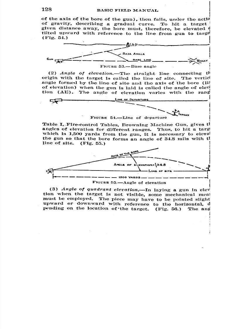
8/22/2019 Basic Field Manual Volume III-1932
http://slidepdf.com/reader/full/basic-field-manual-volume-iii-1932 133/203
128 BASIC FIELD :MANUAL
of the axis of the bore of the gun), then falls, under the actio
of gravity, describing a gradual curve. To hit a target
given distance away, the bore must, therefore, be elevated
tilted upward with reference to the line from ~un to targe(Fig. 54.)
- . :J 1AP--....,;--- B"$s, ANGLS.
GUN ~:::::: BA5~ .. £1
FIGGUE 53.-llase angle
(2) Angle of elevation.-The straight line connecting
origin with the target is called the line of site. The vertic
angle formed by the line of site and the axis of "the hore (liil
of elevation) when the gun is laid is called the angle of elev
tion (AE). The angle of elevation varies with the ran
t,"t O~ O~PAQTUll~
--- -- .............
'~AAGn
FIGGRE 54.-Llne of departure
Table I,"Fire-control Tables, Browning Machine Gun, gives t
angles of elevation for different ranges. Thus, to hit a targwhich is 1,500 ~'ards from the gun, it is necessary to elevll
the gun so tha t the bore forms an angle of 34.8 mils with t
line of site. (Fig. 5:5.)
t>OIl~
\1> o~1\lf,- ----- .................
-...."'"APlGL& O~ IOLE.VATIOM- \~4.8 "........ .........JLlKE. 011' aiTE.
1----------- l~OO YAA.OS -1
FIGGREl 55.-Angle of elevation
(3) Angle of quadrant clevation.-In laying a gun in ele
tlon when the target is not visible, some mechanical meamust be emplo:red. The piece may have to be pointe<1 slight
upward or downwar<1 with reference to the horizontal,
pt'nding on the location of .the target. (Fig. 56.) The ang
--------
~ ~ __ ~
t1
~
~

8/22/2019 Basic Field Manual Volume III-1932
http://slidepdf.com/reader/full/basic-field-manual-volume-iii-1932 134/203
BASIC FIELD l\IANUAL129
tWhich the gun is laid is best measured from the horizontal,
,II the horizontal may always be established by the use of
e spirit level" on the clinometer, and the angles measured
IDward or downward from horizontal. Computation of eleYa.
FIGURE56.-Targets above and below horizontal
lion data therefore consists in determining the angle aboYe
~rbelow the horizontal at which the bore of the gun must be
laid to strike the target. Therefore the angle of quadrant el~
\'atlon is the angle between the axis of the bore (line of eleYa-
HOD)and the horizontal plane at the origin (QE). (Fig. 57.)
(4) Oomputing clevation.-There are three cases to be con.
si<lered in computing elevation, as follOWS:(a) When the gun and target are on the sa,me horizontaZ
TJlanc.-Assume the gun and target to be on the same level and
the range to be 1,800 yards. To hit the target, the gun must be
elevated at an angle of 53.4 mils above the line of site (53.4
lllils being the angle of elevation for a range of 1,800 yards).
'l'he line of site in this case is horizontal; hence the bore is
elevated at an angle of 53.4 mils above the horizontal. As the
QE is the angle which the axis of the bore makes with the
horizontal, the QE required to hit the target in this case is
[;3.4mils. (Fig. 58.)(b) When the target is a,bove the gUll.-Assume that the
target is higher than the gun and at a range of 1,800 yards.
(Fig. 50, CD.) It will be seen that if the gun were given a
QI~of 53.4 mils, the bullet would not hit the target, but would
strike the horizontal plane 1,800 ~'ards from the gun if it could

8/22/2019 Basic Field Manual Volume III-1932
http://slidepdf.com/reader/full/basic-field-manual-volume-iii-1932 135/203
130BASIC FIELD MANUAL
continue its flight. Therefore, to hit the target it is necessl1to give the gun additional elevation. This additional
{'quaIs the angle which the line of site makes with the 110
zontal (base of trajectory). (I~'ig.50, @.) This angle is call
--~-
~J4~.I •
f---- ----1800YAA08_ - - -- ----l}o'IGURE 58.-Gun end target 011 same horizontal plane
the angle of site. It is the angle between the line of sfte all
the base of the trajectory. From Figure-50 @ it is seen thl
the QE is composed of the angle of elevation and angle
site. The angle of elevation, therefore, gives sufficient elevatloto cause the bUllet to go 1.800 yards, and the angle of site give
1~.:>;1!--------1800 YAROS--- --- ---I(i)
•------1800YAnWI- -,
(!)
FIGURE uO.-Target above gun CD and (!)
the additional el(>vation required to. hit the target, because thetarget Is above the gun.
(c) When the target is below the gun (flg. GO) .-The angle
of site is negative when the target Is below the gun. In deter-
mining the QE, therefore, the angle of site is subtr,acted from
the angle of elevation. ItwUl be seen from Figure {)()that the.
QE equals the angle of elevation minus the angle of site.
elevati

8/22/2019 Basic Field Manual Volume III-1932
http://slidepdf.com/reader/full/basic-field-manual-volume-iii-1932 136/203
BASIC FIELD l\IANUAL 131
(d) Genera,l rule for determini11{! QE.-In any case the QE
~qUalsthe algebraic sum of the angle of elevation and the angle
of site; that is, if the angle of site is positive, it is added to
the angle of elevation; if negative, it is subtracted. Angles ofelevation are always positive. If the angle of site is negative
11.1111 numerically greater than the angle of elevation, the result-
FIGURE GO.-Target below gun
ll.ntQE will be negative and the gun when laid will be pointed
helow th(~horizontal; if the angle of site is positive, or negative
hut numerically smaller thun the angle of elevation, the QE
\ViII,of course, be positive.
c. lIfaf.;k and troop dearance.-(1) Mask clea1'Ul1cc.-Before
f\r'ing over a mask, such as a hill or woods, it is necessary to
\{now definitely whether the bullets will dear the top of the
FIGl'REG1.-Angle of clearance
lIlask. This clenrnnce is best determined as is shown by the
fOllowing example: Assume that a target at a given range re-
qUired a QE of 73 mils (fig. (1), and that to hit the top of the
lIlask which is between the gun and the target would require
It Ql~)of 43 mils. If the gun were laid to hit the top of the
lIlask (with a QE of 43 mils), nnd then raised to 73 mils so as
to bit the target, It is nppnrent that when firing at the target
the mean trajectory will be going 30 mils (73-43=30) above
the mask. In other words, the angle of clearance (in this case
30 mils) is always the algebraic difference between the QE to .
the tllrget and the QE to t~1emask.
8/22/2019 Basic Field Manual Volume III-1932
http://slidepdf.com/reader/full/basic-field-manual-volume-iii-1932 137/203
132BASIC FIELD :MANUAL
(2) Troop clearance.-It is also necessary to determine
whether it is safe to fire over the heads of friendly troops
The angle of clearance over the troovs is determined in
manner similar to that presCl'ibe<l for mask clearance.
(3) Required clearance.-Inasmuch as the bullets from
machine gun do not follow exactly the same path when fire
with a given direction and elevation, but form a cone of fir
similar to a stream from a hose, and as QEs to a target, mask
or troops are figured to place the center of the cone of fir
on the target, mask, or troops, allowance must be made to in'
~ure the entire cone clearing the mask or troovs. In addition,
in the case Where safety of troops is involved, the entire cone
must clear the heads of friendly troovs with a sufficient allo''''
ance for their safety even if some slight errors may have beef
made in laying the gun or calculating the data. The angle
of clearance required to fire over a. mask or over friendl1
troops at different ranges are given in Tables II and III, Fire-
control Tables. The angle of clearance above the mask ot
troops must equal or exceed the prescribed mask clearance, orthe safety angle, if troops are involved.
208. Basic data.-From the foregoing it is seen that the lol-.
lOWing information is required to compute data for indirectlaying:
a. The direction of the target from the gun with referenceto magnetic north or some known point used as initial aimingpoint.
b. The range and difference in elevation (vertical interval)between gun and target.
o. The range and vertical interval to the mask or troops.
SECTION III
OBTAINING MAP DATA FOR A SINGLE GUN
209. General.-The method of obtaining map data for a
single gun can best be illustrated by the solution of a concrete
problem. To facilitate the solution, a form of a work sheet,
shown in paragraph 210, is provided. The steps in the work
sheet and in the description of working methods are numbered
to correspond to each other. The two should be studied to-
gether. The arrangement of the detailed work should always
be adhered to. Neatness and proper arrangement will tend to
8/22/2019 Basic Field Manual Volume III-1932
http://slidepdf.com/reader/full/basic-field-manual-volume-iii-1932 138/203
BASIC FIELD l\fANUAL 133
lb.inimize errors and will aid in the checking. of the work by
another officer, which should be done whenever practicable.
210. Typical problem.-a. Situation (fig. 62).-Fire-control
lb.llp,Fort Benning, Ga., 1:20,000; sheet 1. The situation is
as follows:
A gun is at (17.54-19.77).
The target is at junction of road anu trail at (17.2(3.-17.58).
The lonepine on Maxey Riuge at (17.04-19.04) will be used
as an initial aiming point.
Mask is Humphries Hill.
There are friendly troops on an east-west line at. (17.35-
18.26).
b. Requirement.-The firing data, to include the following:
(1) The QE (for laying in eleva tion ) .
(2) Tbe base angle and magnetic azimuth for laying in
direction.
(3) A statement as to whether or not the mask will be
Cleared.
(4) A statement as to whether or not it will be safe to fire
oVerthe friendly troops.

8/22/2019 Basic Field Manual Volume III-1932
http://slidepdf.com/reader/full/basic-field-manual-volume-iii-1932 139/203
134BASIC FIELD MANUAL
100 0 1 2. 3 4 5 6 ., 8 9 10ooyd3[H H H H H H
CONTOUR INTf.RVAL; 10~TFIGURE 62.-Plottlng single gun, map problem

8/22/2019 Basic Field Manual Volume III-1932
http://slidepdf.com/reader/full/basic-field-manual-volume-iii-1932 140/203
BASIC FIELD MANUAL 135
WORK SHEET: SINGLE GUN, MAP PROBLEM
I'CGkuIation.s
Ma WxtoooR
2~.3111000
1.207
.. -lO.~
M' W x 1000"-.-Q --• +3.3i( 100Q...
10~3
+.3.0
At 2:300 -100.7AtZ2.oo'~
11•.5-a.ll-.l)05
90.0
4\.0
340
)-70-eo.3
(I) 1. Mar n. ~nmm~ J:,re Conl:ro1May Shui: No.1
(1-2.0,000) .2.@l\ at C17.5'!--l9 772'fargot at (17.2.(, hso)
(~)- Mash at HUo\PHBIU HILL
T..oop. at (17.35 llFZ.(,)
lAP o:t. Lon .. p,"$ 0-1: (17.0~ 19.04)
,'S. Dat.a from p1oHing,
a. Rang<!:~10.\ {Gun t.o Tartet 2207'''1__ Gun to M.cuK_-.:.l.::.o.::.6:.~_.-..-
<&u.no Troops _""15:.:Z:.:;)-------
b. t.lqvo'bonsuevat.on Ciu.n 410 ft
(4 ) ~~:~~t~~':s{"tE.Ievoi,on Iroop. -=~-,-7:.0-,-tt-,,--
4. '-Ievatlon Data (calcutated):
a. Gunto Igrtst.(5) VI, G ta 'T (YQrd5)-2~.3
IG) AS, G -to T -10.(,7) A.E., (i to r 90.0(8) Q.E., G to" 79.4
b. Gun 'to Mask
{
V!, G to .M.a.&1\ Cyorsls} +3 •.3(9) A~ G to 1'\0$11. +3.0
Ak.J <& to !'\a&K 17.7-Q£, G to }1~ ZO.2
(10) .Angle of clearance :>9. z.
f
J 2eQd c:ltara.t1ce 7.Z(II) Mll!k will .(wHi-ftOf) be deal'ed;
Clearance over
I'e~.a+52.0
c. Gun to 1r$!ops
{
VIJ (z'{o troops Cyard$) -t~.S
AS, G to iYoop$ 7(Iz.) -_ AE.. Ci to '1't'OOP$ oS .t
Q'-. e;,+.oYroop. Z7.4 ~9.4-(I~) Antle of cICQI'QTl« SZ.o 274-
RC'l'd safety an Ie 41.;:' --'-
04) --{iI'OOP''''ilI (~)bc _ofo) 5Z.0CleQranc4 ever !'<t'l.'J ~A ..:!::..!2..:.L
5. Diredion Data(1:1)_<:'r'o aZimuth. G to 1 ~~29(16) -.Magnd:ic a:.<mu-l:h, Go to 'J' ~>"(11) -Clc:ue (\"~le . R 4-90
Af. 1600. 40.4-At.1500.~
.s...
-idt"... \..safrij'AnjIClIboo ..
1500 • 40.3
40.3 4"2l.
G. Firms "Daola -'-~-
flAP Lone p,M at (11.04-1' 0;4:) 41.3 A~r.
06)- P.>Q5e angloz R490 .fI'tognct,(', Qr;lmu{h.~33~1~G~
19 1='1uNd Qt to neot'e.st. mil
C. Preliminary steps (see work sheet above).-Step i.-Note
the title and l';eale of the map.Step 2.-Locate gun, target, mask, troOl)S, and initial aiming
lJoint on the map, giving locations by coordinates or by de-
Scription. To mark such points on the map, a pin or similarly
=
-
~
~ -
-
-
__
~ -- -=~~~~~~~~~---
_
__ ---- __
__ __
'
- ~ --
~
~
~~ _
~~ __
8/22/2019 Basic Field Manual Volume III-1932
http://slidepdf.com/reader/full/basic-field-manual-volume-iii-1932 141/203
136 BASIC FIELD MANUAL
sharp-pointed instrument may be used. A circle may be dra",l1
around the pin point with a pencil to facilitate finding it.
Step S.-Using the map scale, or the sca'e on the protractor,
measure the ranges, gun to target, gun to mask, and gun totroops. These are found to be 2,207 ~'ards, 1,083 yards, and
1,523 ~'ards, respectively.
Step 4.-Determine the contour elevations of the gun, target,
mask, and troops. The gun position on the map is exactU
on the 41Q-foot contour, and its elevation is therefore 410 feet.
Similarl~', the elevation of the target is found to be 340 feet,
that of the mask 420 feet, and the troop elevation 370 feet.
Elevations of points lying between contour lines are found
by interpolating between the proper contour elevations.
Step 5.-Determine the vertical interval gun-target by sub'
tracting one elevation from the other. The difference in ele'
vation or vertical interval gun-target is 410-3tO or 70 feet;
that is, the target is 70 feet lower than the gun. This
tance must be reduced to yards and equals minus 23.3 yardS;
minus, because the target Is below the gun.
Step 6.-Calculate the angle of site. It being determinetl
that the range gun-target is 2,207 ~'ards and that the target
Is 23.3 yards below the gun, the angle of site may be cal'
culated by the mil formula:
}[="TV X 1,000.R,
Substituting the values for "TV (width or height) and R (range),
J l (the angle of site) Is determined as follows:
,M -23.3 X1.000 10.62,207
pIlnus because the target is below the gun.)
Step 7.-Determine the angle of f'levation. If the gun wer
laid at an elevation of 10.6 mils below the horizontal, the axi.of the bore would be pointed at the. target, provided the gull
has previously been laid for direction. However, since tbe
range to the target is 2,207 yards, the gun must be elevated
through an additional angle sufficient to cause the bullet to
carry that far. Angles of elevation for ranges of hnndrf'ds 0
yards are shown in Table I, Fire~control Tablf's. The angle
of elevation for 2,300 yards is 100.7 mils and that for 2,200
yards is 8!).2. Interpolating: between 2,200 and 2,300 (see in'
structlons given with the table), the angle of elevation for
2,207 is fo.nd to be 00 mils.
<1i
-

8/22/2019 Basic Field Manual Volume III-1932
http://slidepdf.com/reader/full/basic-field-manual-volume-iii-1932 142/203
BASIC FIELD MANUAL 137
~tep B.-Determine the angle of quadrant elevation. From
at has already been computed it is seen that, to hit the tar-
:t, the gun would have to be elevated -10.6 mils for angle
site and 90 mils for range. lienee the QE equals the alge-alc sum of the angle of site and the angle of elevation
"10.6+90) or 79.4.
~OTE.-The QE for any range and the vertical interval (VI) may beU!npddirect from Tables IVa and IVb, Fire-control Tables, without
: neceflsity of computing the angle of site. Instructions are given
h the table. Either mf'tho(}may be used. The tables wlII save time
thoRefamiliar with their use, but the method described above should
stUdied in order that the fundamentals of indirect laying may berOugblyunderstooJ.
~.Mask clearance.- (1) GC'fICral oo'nsiderations.-In indirect
~lngthere is generally a solid obstruction such as a hill or
IOds between the gun and the target. The map must be in-
cted to determine the location of this mask. The highest
~rvening crest is generally the mask, though sometimes it
ly be a lower obstruction near the gun or target. If thereany doubt as to which obstruction is most likely to mask
fire, clearance is figured for all such obstructions. Trees,
Cial1y thick woods, must be considered, and their height
ded to the height of the mask. Fire may be delivered
rOugh a thin fringe of trees, if there are no friendly troops
'ated near their fill' edge. Thick woods will stop or defiect
~t of the shots and render the fire ineffective. 'Voods areIlally shown on maps, but, if not, reconnaissance will deter-
!leWhether they must be considered. In this particular case-
inspection of the map shows that the point most likely to
:erfer(~with the fire is Humphreys II ill. A line is drawn
11ll the gun to target, and the highest elevation cut by this
e as It crosses Humphreys Hill locates the mask.
~tep 9.-Determine QE to mask. When obtaining data from!lap, the best means of determining mask clearance is to com-
te tile QE to hit the top of the mask, and then see if the
to tile target, which has already been figured, exceeds the
to the mllslt by the required amount. The QE to the mask
determined by the same methods as were described for QE
turf.\:et. In this case the QE to hit the mask is found to
20.2.
~2)Gomputinq maJ;k vlearance.-The mask clearance is com-
:(\dhy the following stpps:
ORfl53°-32--10
~
~
'

8/22/2019 Basic Field Manual Volume III-1932
http://slidepdf.com/reader/full/basic-field-manual-volume-iii-1932 143/203
138 BASIC FIELD l.IANUAL
Step 10.-Subtract the QE to the mask (20.2) from the
to the target (79.4); the difference is the angle of c1earll(fJ D.2).
Step 11.-Required clearance. To determine that this cleance is suffici(>nt to allow the entire cone of fire to clear
mask, the requir(>d mask clearance for a range of 1,083 yll(the range to mask) is obtained from ~rable III,
Tables. The required clearance for 1,083 yards is 7.2
'1'he angle of clearance is 5D.2 mils; and since only 7.2
clearance is required, the mask will be cleared by 52 mils 0
the required clearance. (E'ig. G3.)
e. Troop salety.-Safety for overhead fire is detenui1
in the same manner as mask clearance. The position or P
tions occupied by friendl~' troops in the line. of fire
been plotted, it may be neeessary to determine troop safety
eaeh position. 1I0w(>ver, an experienced offieer will usuallY
TOTAL CL£ARANC£
5SoZI11LS
R£Q(/IR£.DCLEARANCe.
7.2, MILS
FIGCRE 63.-Clcarance over required
able to select the position whieh is most likely to be endange
and thus determine snfety by a single calculation. FolIo'"
are the steps required in this computation:
Step 12.-In this ca!o;Che friendly troops are on an eastA
line at (17.35-18.26). The QE to the troops is found in
same manner as described for finding the QE to the target.
The QE to the troops is found to be
Step 13.QJ;J to targeL 1,
QJ;J to troops_____________________________________
Angle of clearance_______________________________ D
Step 14.-The required safety angle for troops at a range
1,523 yards (the range to the troops) obtained from Table
Fire-control Tables, is found to be41.3
mils. The angle!
clearance, 52.0 mils, exceeds this angle. Itis therefore safe
fire. (Fig. 64.)
f. Obtaining directi{)n data.-Mask and troop clearflJl
should always be ehecked before determining direction (1:1
I!-'ire-co
II
h8,,
~

8/22/2019 Basic Field Manual Volume III-1932
http://slidepdf.com/reader/full/basic-field-manual-volume-iii-1932 144/203
BASIC FIELD MANUAL 139
I
'lluflicient clearance <loesnot exist, this will obviate the neces-
ty of figuring the latter <lata. There are two general methods
laying the gun for <lirection, as outlined in paragraph 207a.
e first requires the magnetic azimuth, gun to target. This
:1ll1uthmust always be determined no matter which method
Used so as to insure accurate laying under any condition of
lbility. The second method requires an lAP and base angle.
~elllagnetic. azimuth can not be determined directly from the
aI>. The grid azimuth (the angle measure<l cloekwise from
Id north to the line gun-target) is measured with a protrac-
~. This is converted to magnetic azimuth by using the declina-
)n Constant of the instrument which is to be used in laying
gun. If the declination constant of the instrument is not
laWn,then the grid azimuth is converted to magnetic azimuth
applying the magnetic dC'clination shown on the map, cor-
TroofoS
1.'IGUHE
G4.-Clearance over required safety angle
ted for the mean ,annual declination change. In this problem
I datu for both of the general methods are shown as follows:
~tep 15-Grid Gzimuth..-To determine the grid azimuth,
Ilong the line gun-target until it intersects a north-south
d 01' draw a line pnrallel to the north-south grid which
!rsects the line gun-target. 'Vith a protractor, centered OIl
! intersection, read the angle clockwise from grid north to
,line gun-target. In this case the grid azimuth is 3,329 mils.
rtcp 16-:Magnctio azirnuth.-li'or Fort Denning, Georgia, the
-netlc declination correcte<l for annual change 1929 is ap-
I)(imutely 13 mils east. This <leclination of 13 mils must
l'efore be subtracted from the gri<l azimuth, which gives a
gnet1c azimuth of 3,316 mils.
'tep 17-B(JA8e a,Jlgle from IAP.-Draw a line from the gun
lUgh the lAP. With a protractor measure the angle be-
'en this line and the line gun-target; this is the base angle,
angle through which the gun must turn froUl the lAP in
~
~

8/22/2019 Basic Field Manual Volume III-1932
http://slidepdf.com/reader/full/basic-field-manual-volume-iii-1932 145/203
BASIC FIELD MANUAL
order to be laid on the target. In this problem it is,
~m~ .
g. Step 18-Firre da.t(ll ....:-The data required to lay the gun
direction and elevation are noted. With the magnetic
or base angle from the lAP, and the QE, the gun is laid to
the target as described in Section VII.
SECTION IV
OBTAINING MAP DATA FOR GUNS GROUPED IN
BATTERY
211. General.--:-The method of computing data for a batte!
can be illustrated best by the solution of a concrete
The problem selected for solution involves a b~ttery of
guns engaging respectively an oblique, an enfilade, and a poi
target. The principles shown apply to any number of
grouped in battery. All calculations made in filling out t
battery chart should be carried out to include the first
place, and so entered in the body of the chart. The
in the fire orders, how~ver, are made in the nearest
mils. Refer to Figure 65 for a diagrammatic explanation
battery angles.
212. Situation. Fire-control map, Fort Benning, o
~: 20,000; sheet 1. The situation is as follows (fig. 66):Base gun: No~1 at (16.44-18.12).
Battery front: 100 yards extending northwest.
Initial aiming point: Lone pine on Maxey Ridge at (17.
~9.04).
Target A: At (18.54-18.97)-(18.48-19.18).
Mask: At (17.87-:..18.70)(allow 80 feet for trees).
Target B: At (18.46-19.42)-(18.70-19.60).
'Troops: At northwest-southeast line through (17.85-19.00
"l'atget C: (18.03-19.40).
Base lines on target A; (Base lines will be located onmost important target or in. the most convenient directioO
213. Requirement.-Completion of the battery chart shO?
in illustration. (Numbers in parenthesis refer to step numb
e
in the text.) .
214. Proce~ut:e.-Step l.-Plot the battery position on
map by locatmg the base gun (usually, as in this case,
No. 1 gun) and drawing the battery front to scale, in
designated direction. .
140
Rig
' aZimu
proble
fo
gu
deciII
entri
wh
-
J
'

8/22/2019 Basic Field Manual Volume III-1932
http://slidepdf.com/reader/full/basic-field-manual-volume-iii-1932 146/203
5 Base stakes out.
(37)
L8
L16
R580
R500
2
4
FIRE ORDERS
- No.4 Time0.3 Trav-Search Rateo!- erse
QE per gunup flre
From ToE - ------ --- --- ---107 109 36 20 125
- --- --- --- --.1591~
12 20 125
---
"I~__6 16_ ._
--
- Task C Task DaskB
L;;'on base lines Lay on bas e l ines Lay on base l ines
Sight Dial Sight Dial Sight---- R9 L300 R5LiSO-- ---L160 R15 £280 . R9
---- --- --_.L160 RI £260 RlS
--- ---'-LUo R7 £240 R17
- Green Yellow
-
--~8953-32 (Face p.140.)
BATTERY COMMANDER'S FIRING SHEET
Date, 1 APT 30 T'
~a~Jery: A, Group i1Je 6Unir is t P lu t. , Co. D , 29th In /.r~ az~muth I. A. P'6 Deel grid to magnetic, E 13..
Gnd aZimuth base l ine, ~~2I0. Magne tic azimuth base l ine, 1 ,197 .
PREUMINARY ORDER
Dial Sight
R600 L12
(34)
Lo ne pine a t
1 lit.P. (17.04-19.04)2 guns on I. A. p3 No.1 gun base gun:
rn i
Task Wind- ~I No. 2 / Nage
QEQE--A- ...;...--
_~1105_
B_ 123 i 141
__C_I=r---;-i. , ,-D crr:cREMARKS
NOTE.-Numb' : . fer to step numbers in text.er s In ParentheSIS re
REMARKS
Prepared by A. S. N ..
Checked by R. B. R .
BA' I'TEfRY CHART
89.7
187.9
Batte ry angle ofparal lax 96.
Dis tr ibut ion d iffe rence (12) for paral le l f ire,
32.
Grid azimuth I. A. P ., (8) 598.
Gr id az imuth base l ine s, (9) 1210.
Magne tic azimuth base l ines (10) 1197.
Base angle -right ( le ft), (11)612.
89.8
117.3
169.21.2
15.3
90.0
GUN ELEVATIONS
TASK ORDERS
(35) (36)
Tas~Target ~~~:- Search Rate of -No. ----L
Angle of Bat angle f t per fi T a- b---shift D or C ron
l) per gun re Y on ase lines
(mi s gun
Dial
(13) 0 (14) DL58 (15) 100 ---;:; (16) 20 --- ;; ; 1
_------ 2 RI9
+20.0 (21) L189 (22) CR42 0 (23 )12 (24) 20 125 -3- --;;;;-..:..- RI8
---- ---28)L305 (29) CR48 0 (30) 16 (31) 16 125 _4_ L40 R1B
_---------- Stak~
(7) +44.29.9
ClearanceVI QE ov~r
troops troops reqUIredor ma sk or mask m:~~ l; :r -
safety angle
Mask or troops:
A Mask , t re es a t ( 17 .87-18 .70) .
C
B Troo ps on NW-SE . line throu gh (17 .85-19.00).
D
(6) 1,567 +33.3
Range,troops,or mask
(20 ) 1,675 +33.3
90.289.7
133.0187.3
VI tar- QE tar-get
(yards) get
GUN ANGLES FROM BASE LINE
(4) 2, 283 +32. 7(5) 2, 327 +35.3
Rangetarget(yards)
(19) 2,4 20 +40.32,750 +41.3
(27) 2,067 +30. 02, on +28.7
A
B
c
D
Task
Battery A, Group III. Composition, 1st p la t. , Co. D , 29th Inf ., No. of Guns 4.Base gun No.1. Battery front 100 yards. Commanded by Lt. R. B. Jones.Extending NW. Place, For t Benning , Ga.Location of base gun (16.44-18.12).I. A . P. Lone pine at (17.04-19.04).Location ofbase l ine on Tusk A.Map FOTtBenning, F. C.1;1J0,OOOheet No.1.
Task:
A (18.54-18.97)-(18.48-19.18)
C (18.03-19.40)
B (18.46-19.4.2')-(18.70-19.60)
D
Dif. DorC 1 2 3 4 Dif.QE+ I 1or
--_.A (17) DL19 0 L19 L38 L58 (18) +2.0 113.3 1
B (25) CR14 L189 L175 L161 Ll1,.7 (26) +18.2 133.0 1
---' --.
c I (32) CRl6 L30/j L289 L273 L257 (33)-.2 90.2
--I
I
---. ._-_.I. I
D!I
_
"
---
---
____ ~ __ ---
~
---
-- -
- --
---
-- __
~ ~ ~ ----------
___ ________
~
-

8/22/2019 Basic Field Manual Volume III-1932
http://slidepdf.com/reader/full/basic-field-manual-volume-iii-1932 147/203
BASIC FIELD l\IANUAL 141
UGt.ND
Q botte~ o':"J feof paralIQXb e>ase anql.e
C flQH~ ansl« of dlstrlbutloR
d ArtlJle of .slilft.
eatu':j Qn~rt; of co~encto!eos~ Gun
FIGURE 6ri.-Battery angles
tio4
Step 2.-Locate targets, initial aiming point, an~ troops or
task on map .
.215. Solution of Task A.-a. Step 3-Plotting.-Draw lines
'om hoth flanks of the ha ttery to the initial aiming "point andI the targets. The line from the base gun to the right of'
Ie principal target is called the base line of the battery. The
ase lines of the other guns are parallel to the base line of
Ie battery.
b. Quadrant elevations.-When the range and elevations of
ilJ .k guns are different, it is necessary to figure QE separately
r each of the flank guns of the battery. This is done as
lIo\Vs:
Estel) .~.-For No.1 gun (to its part of Task A) :nange 2, 283
Ell~vation "0 320
El evat i on T_______________________________________ 418
"\71- ... Plus 98 feet equals plus 32.7 yards.AS Plus 14.6
AE 08.7
QE 113. 3
~
~

8/22/2019 Basic Field Manual Volume III-1932
http://slidepdf.com/reader/full/basic-field-manual-volume-iii-1932 148/203
142 BASIC FIELD MANUAL
Step 5.-QE for No.4 gun (to its part of Task A) :Ek~nge____________________________________________ 321
oio', 3Z~
Elevation G _Elevation T______________________________________ 4'VL Pluf3 10.:; fept f'quals plus 33.3 yal'd~AS __~________________________________________~us 1~
AE 104. I
QE 11
fB
.scale: 120000
tO j ENtEA'~d U H j4rO Jctrr18
Contour Interval 10ft..FIGURE GG.-Plottlng battery map problem
c. Mask.-The mask is the edge of the woods. As No.1 gl
has the lower QE, the mask clearance is determined for
alone. (In some cases it might be neeessary to cornpute mll
clearance for both flank guns, to be sure all pieces would cle
the mask.)
Step G.-For No. 1 gun-Range to mask 1,5
Elevation G______________________________________ 3
Elevation m!lsk 300, plus 30 f('et for trees equal 420 fe
VL Pluf3 100 feet, or pTus 33.3 yu!'
AS Plus 21
~
~- - - - - - - - - - - - - - - - - - - - - - -
__

8/22/2019 Basic Field Manual Volume III-1932
http://slidepdf.com/reader/full/basic-field-manual-volume-iii-1932 149/203
I
I
f
BASIC FIELD MANUAL 143
Step G.-For No.1 gun-Continued.AI ~ 38. 6
( ~E 5~9
Step 7.-1\1ask' elellrancl:'.QI!J to T ,,;. 113.3
QI<J to mask_______________________________________ 59.9
Clearnuce 53.4
'l.'he required clearance is 9.2, from Table III, Fire-control
'l.'ables. The elearance over that required is plus 44.2, and the
Illttsk
does not interfere with firing.NOTre.-IIaving determinpd that the mask will be cleared, the next
~tep 18 to determine direction data.
d. Step 8-Grid azimuth of initial aiming point.-With a
Dl'otrllctormeasure the grid azimuth of the line from the base
~Un to the initial aiming point. Itwill be found to be 598 mils.
i e. Step 9-Grid azimuth of base lines.-With a protractor
Illf>-Qsureile grid azimuth of the line from the base gun to its
nank of Task A. It will be found to be 1.210 mils.f. Step 10-Ma!lnetio azimuth of base lines.-(l) Convert
the grId azimuth of the base line to magnetic azimuth by cor-
l.'etillgfor thp. declination of the magnetic needle from grid
~Orth for the particular locality (13 mils east for Fort Ben-
Illng) : 1,210-13=1,197.
l (2) If the declination constant of the instrument to be used
to lay the battery is known, that figure, instead of the declina-
tion shown on the map, will be used to convert the grid azimuth
1° 1llag-lleticf1zimuth.
! NOTFJ.-Refer to Part Two, Chapter 1, Section I, for n dIscussion of
l~e Il1l'thod of obtaIning the declination constant of an aiming circle
~nd an explanation of its use.
fl. Step l1-Base angle.-With the protractor measure the
ll~leformed by the line from the base gun to the initial aiming
)lnt nnd the base line of the battery. It will be found to betght (i12 mils.
h. Step 12-Battery angle of parallam.-Measure the angle
rlned by tl}(~ lines connecting the flanks of the battery and
b lAP with a protractor. It will be found to be 96 mils.~h'ide by the number of guns to be turned away from the base
llill(in this case 3) to get the distribution difference for parallel
~e-{)Hdivided by 3 equals 32.
~
~

8/22/2019 Basic Field Manual Volume III-1932
http://slidepdf.com/reader/full/basic-field-manual-volume-iii-1932 150/203
144 BASIC FIELD :MANUAL
i. Step 13-AngTe of 8hift.-Base lines are on Task A in tl1
problem; therefore the angle of shift is zero.
j. Step 14-Batterll angle of di8tribution.-When the widththe target is such that parallel fire will not exactly cover it, t
fire must be distributed so as to cover all parts equally.
the angle through which the gun on the flank away from tl
base gun is turned to lay on its flank of the target is measure
then the angle which the other guns will have to turn may
computed. This angle is determined as follows:
(1) Draw a line from l'o. 4 gun parallel to the line frol'o. 1 gun (base gun) to its flank of the target.
(2) Measure the angle between this line and the line co
necting l'o. 4 gun with its flank of the target.' This is t
battery angle of distribution. In this case it is Left 58.
k. Step 15-Traver8e (when ta.rfJethas width).-(1) DraW
line from No.1 gun to the left flank of the target. With
protractor measure the angle between this line and the IIconnecting l'o. 1 gun and the right flank of the target. Tb
angle, the battery front in mils, will be found to be 100 mi
(2) Divide by the number of gun intervals (in this case
to find the traverse per gun-1oo divided by 3 equals 33.3.
the fire order use 32 or 36, so that the traverse per gun
be divisible by 4.
l. Step lG-Sea,rcking.-In order to compensate for IIIerrors, errors in figuring data and applying them to the gu
and to insure overlap of beaten zones on enfilade targets, so
search is always ordered. This search is applied to each gt
The proper amount of search to order depends on the type
target, the range to the target, the slope of the ground at t
target, and the accuracy of the data. In other words, t
amount of search is a matter of judgment on the part of t
officer figuring the data. However, as a guide, for targ
located on level ground a search equal to 20 per cent of t
angle of elevation of the base gun but not to exceed 20 II
should be ordered. This amount of search is approxlmat
correct for normal indirect-laying ranges based on the followl
assumpUons: I!""irst,that a runge error of 10 per cent should
provided for, and second, that a battery of four guns can
cover effectively an area of greater depth than 200 yards.
this case 20 per cent of the angle of elevation (V8.7 mils)
'"

8/22/2019 Basic Field Manual Volume III-1932
http://slidepdf.com/reader/full/basic-field-manual-volume-iii-1932 151/203
i
r
BASIC FIELD MANUAL 145
the base gun is 19.7 mils; hence the amount of search to be
Ol'der(ldis 20 mils, as the search should be divisible by 2.
m. Step ["I-Gun angles from base lines.-By dividing the
battery angle of distribution (see j above) by the number ofgUnswhich. turn from the base gun, the gun angle of distribu-
tionis obtained. In order to place each gun on its proper part
Of the target, No.2 gun turns through this angle from the base
Un; No.3 gun turns twice this angle; and No.4 gun three
hues this angle. In this case, the gun angle of distribution is
19 (58 divided by 3), and the direction is left. Hence, No. 1
eingthe base gun and the angle of shift being zero, the anglesor the guns are as follows:
~o. 1, O.
I ~o. 2, left 19 from its base line.
.~o. 3, left 38 from its base line.
, ~o. 4, left 58 from its base line.
n. Step 1S-Gun ele-vatiol1s.-(1) \Vhen the flank guns have
~itrerentQEs, it is necessary to distribute the difference be-
t\\'eenintermediate guns, as follows: .i ' Qli.:for No. 1 equals 113.3
l QE for No.4 equals 119.4
i Difference 6. 1r (2) Divide by number of gun intervals--G.1 divided by 3
;qUals2.0; this quotient is added (since the QE of No.4 gun:~the larger) successivelr to the QE of each gun, as follows:QI~ No.1 gun 113.3
Q~J No.2 gun 115.3
r QI~ No.3 gun ..,. 117.3
, I QI~JNo. 4 gun '- 119.4
, 216. Solution of Task B.-a. Quadrant eleratio1ts.-This is
In entllade target. Lines have been drawn from No. i and No.guns to their flanks of the target. The QE for each flank
~n is computed separately as in paragraph 215.
Step 19-I QE for No.1 equnls -' 133.0
l QE for No.4 equnls 187.3
Ib. Pt'icndlll troops.-Troops are on a northwest and southeast
~e through (17.85-19'{)O). As No.1 gun has the lower QE,
e cll'urance is figurt>d for it alone, as follows:
~
----------------------------------
~
~
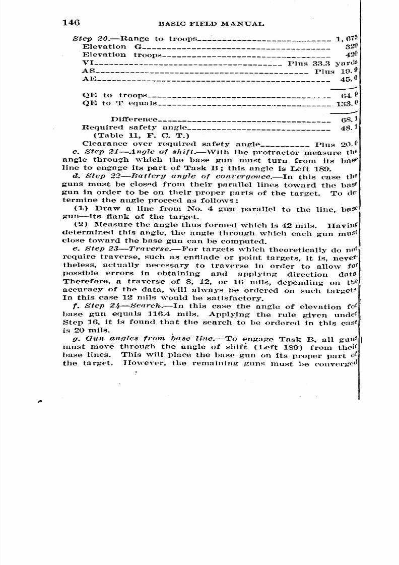
8/22/2019 Basic Field Manual Volume III-1932
http://slidepdf.com/reader/full/basic-field-manual-volume-iii-1932 152/203
I
146 BASIC FIELD MANUAL
Step 20.-Range to troops 1, 675
Elevation G______________________________________ 320
Elevation troops__________________________________ 420VL Plus 33.3 yard9
-------491E to troops_____________________________________ 6.QE to T equals .. 133.0
--->ifference___________________________________ 68.1
Required safety angle_____________________________ 48.1
(Table 11, F. C. T.)Clearance over required safety angle Plus 20.0
c. Step U-.4ng7e of shift.-With the protrnctor measure tIle
angle through which the base gun must turn from its base
line to engage its part of Task B; this angle is Left 189.Q
d. Step 2.2-Battery angle of cOftverg(Jtlce.-In this case tlJe
guns must be clos~d from their parallel lines toward the base
gun in order to be on their proper parts of the target. To de'termine the angle procee(l as follows:
(1) I>raw a line from No. 4 gup. parallel to the line, baSe
gun-its flank of the target.
(2) Measure the angle thus formed which is 42 mils. Havi!lg
determined this angle, the angle through which each gun ml1~t
close toward the base gun can be computed.h
e. Step 23-Traverse.-I!'or targets \vhich theoretically do not
require traverse, such as enfilade or point targ,ets, it is, never'
theless, actually neeessary to traverse in order to allow tot
possible errors in obtaining and applying direction datS,
Therefore, a traverse of 8, 12, or 16 mils, depending on tlJe
accuracy of the data, will always be ordered on such target~'
In this case 12 mils would be satisfactory.
f. Step 24-Search.-In this case the angle of elevation tot
base gun equals 116.4 mils. ApplyIng the rule given undet t
Step 16, it is found that the search to be ordered in this case
is 20 mils.g. Gun angles from ba8e line.-To engage Task n, all gUJl5
must move through the angle of shift (Left 189') from theit
base lines. ThIs will l,lace the base gun on its proper part of
the target. However, the remnining guns must he convergc11
1~~~~~~~~~~~~~~~~~~~~~~~~~~~~
I

8/22/2019 Basic Field Manual Volume III-1932
http://slidepdf.com/reader/full/basic-field-manual-volume-iii-1932 153/203
BASIC FIELD MANUAL 147
~o\Vardthe base gun in order to be on their proper part of
lhetarget. These two operations are combined in figuring the
~Un angles from base lines as follows: The battery angle of
~Onvergenceis Hight 42 mils. The gun angle of convergence
'S found by dividing this amount by the number of guns which
Urn toward the base gun (42 divided by 3 equals 14). Since
:he convergence is in the opposite direction to the shift the
tun angles from base lines are-
Step 25.-No. '1, Left 189.
NO.2, Left 189 minus Hight 14 equals Left 175.
. NO.3, Left 189 minus Hight 28 equals. Left 161.NO.4, Left 189 minus Hight 42 equals Left 147.
h. Step 26-01ln elevations.-The "differ<.>ncen QEs is dis-
l'ibuted as for Task A. (Step 18.)
217. Solution of Task C.-a. Step 2i-Q1Iadrant ele'fa-
lans.-Lines have been drawn from the No.1 and No.4 guns
o the target. QEs for the flank guns are computed separately
lEI in paragraph 215. TIle Qgs are found to be: No. 1 gun,0.2,No.4 gun, 89.7.
b. St(~P 28-Angle of shift.-'Vith the protractor measure
he angle (Left 305) which the base gun must turn from its
'aSe line to engage its part of Task C.
c. Strp 29-Batterll angle of eonvcrgcnce.-In this case, the
Inesof fire must be closed from their parallel lines toward the
'ase gun. The battery angle of convergence is obtained as fol-)\Vs: 'Vith protractor measure the angle formed at the target
the lines drawn from the flank guns to the target; it will
e found to be Right 48 mils.
d. Step 30-Travcrse.-A traverse of 8, 12, or 16 mils may
ordered. (Step 23.) Assuming the exact location of Task C
ifJicult to determine, a traverse of 16 mils is ordered in this
Qse.
e. Step 31-Seareh.-A search of 16 mils is ordered. (Stepa.)r. Step 32-0un angles. from base lines.~The gun angles
~Olll hllse lines, determined flS in U above, are as follows:
No.1, Left 305.
No; 2, Left 305 minus Right 16 equals Left 289.
No.3, Left 3m minus Hight 32 equals Left 273.
No.4, Left 30;:)minus Hight 48 equals Left 2;:)7.
l
~
~
"

8/22/2019 Basic Field Manual Volume III-1932
http://slidepdf.com/reader/full/basic-field-manual-volume-iii-1932 154/203
148 BASIC FIELD MANUAL
g. Step 33-Gun elevation.'l.-Some point targets may require
different. QEs for the different guns. In such case the QIDot
each fiank gun is calculated and those of the interiorfound as before. In this case each gun has approximately tbe
same QE, DO mils. Exact figured QEs are found as in Step 18,
218. Orders.-The body of the chart having been completed,
the data contained therein are used to complete the orders illthe battery commander's firing sheet. These orders are used
in making out the gun charts (s(~ebelow) by the .battery cow'
mander when he issues the fire orders to the Hattery as a whole.These orders are filled in as shown on the battery commander'Sfiring sheet, battery chart. .
GUN CHARTGrid azimuth of base line, l,ttO.Magnetic azimuth of base line, 1,197.
Gun No.~'Battery l'
Date, 1 Apr., 9
TimeTask
From To D!al Sight Norm AdJ
~~~:. Search Rate Color of
per up per of fire stakeSgun gun
---- ---- -- ------- --- --- ------'
16 16 1$15 Ye[{otl)
-------_ ....
R 13 82260
A______ L to R 18 107 36 20 125 Red
---- --.----------'B______ L 160 R 1 159 1$ 20 125 Green
------ --------- ....
--------REMARKS:
Step 34-Preliminar1l order8.-Lines 1, 2, 3, and 5 are self'
explanatory. Line 4 is filled in by entering, in terms of dial
and sight, the an~les necessary for each gun to turn in order
to lay on their respective base lines.
Step 35.-4. Task orders (Task A).-The angle of shift
and the gun angles of distribution or convergence are coDl'
bined into one command and placed ovposite each gun in termS
of dial and sight. Since the angle of shift for Task A is zero
(Step 13), only the gun angles of distribution are considered.
(Step 11.)b. Fire orders (Task A) .-To vrevent gunners searching be'
low the safety limit when firing over the heads of friendlS
troops, gunners are trained in battery drill to search onlS
upward from the QE ordered. Whether the initial bursts will
be fired with fi:;ured QEs nnd the search applied in both direc'
gUll
"
'
-------
-- _

8/22/2019 Basic Field Manual Volume III-1932
http://slidepdf.com/reader/full/basic-field-manual-volume-iii-1932 155/203
BASIC FIELD :MANUAL 149
tions, or fired with minimum QEs with all search Up is a
matter of judgment on the part of the officer in charge of the
:firing. If the' mission is merely to cover an area which will
include the target, all search will be Up, as the manipulationis more simple, and there is less danger of searching below
the safety limit. If the nature of the target is such that it
appears essential to place the initial bursts, if possible, 011 the
target, then the figured QEs should be uSfd, search applied in
both directions, and depression stops placed to prevent reduc-
tion of QEs below the safety limit. In this case, the fire order
is bnsed on the assumption that all' search should be Up.lIence the QEs announced in the fire order are less than the
computed QEs shown under" Gun, elevations" by an amount
equal to one-half of the ordered search. Example: The com-
Puted QE of the hase gun (Step 18) is 113.3; this is reduced
by 10 mils (Step 16), giving 103.3. The QE ordered is 103
since QI1Jsare always taken to the nearest mil. Where the
troop clearance is not sufficient to permit the reduction of theQE by one-half the amount of search, the QE is reduced by
the amount of troop clearance, and a search Up equal to the
sum ot the troop clearance and half the figured search is
ordered. Example: I1'igured QI<J60, troop clearance 4, search
per gun 12. The QE announced in the fire order would be
60-4 or 56. The search announced in t'he fire order \vould
be 4-t:6 (one-half of 12), or 10.
NOTID.-Reduction of computed QEs must not exceed the clearance
over required safety angle. (Step 20.) The traverse and search are
filled In by reference to Steps 15 and 16, respectively.
Sleps 36 anit 37.-0rders for Tusks Band C are filled out
in a similar mfl;nner.
SECTION V
OBTAINING DATA 'VITIIOUT A MAP FOR A SINGLE GUN
219. General.-When no suitable map for use in obtaining
indirect laying data is available, data are obtained by instru-
ments from a ground reconnaissance. These ground methods
have been named TOG methods, since they involve the three
points T (target), 0 (observation point), and G (gun).
Wherever practicable, a single or, from which both gun and
target can be seen, should be selecteJ.; where this is not pos-
Sible, it will be necessary to use two or more OPs.
220. TOG, single OP method; procedure.-a. The method
of obtaining data for a single gun by means of TOG, single or
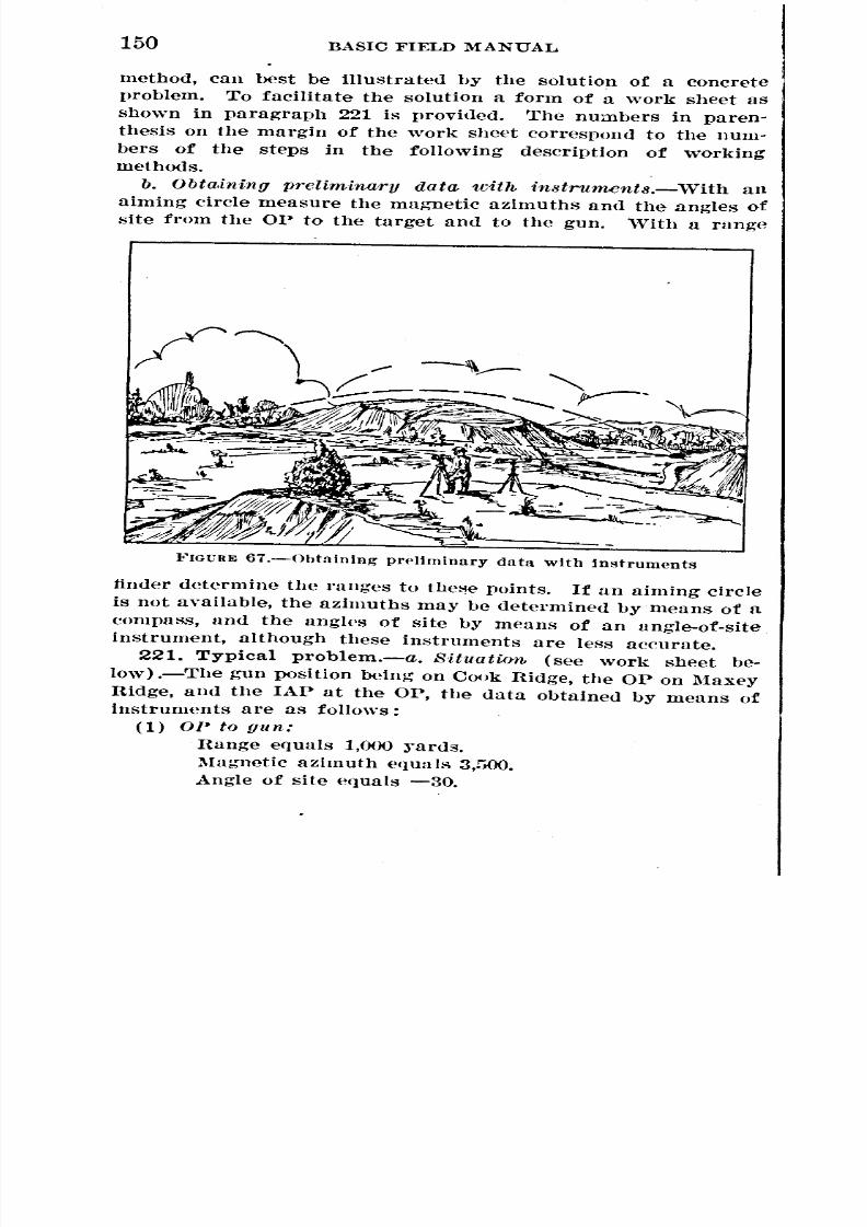
8/22/2019 Basic Field Manual Volume III-1932
http://slidepdf.com/reader/full/basic-field-manual-volume-iii-1932 156/203
150 BASIC FIELD MANUAL
method, can best be illustrateo. by the solution of a concrete
problem. To facilitate the solution a form of a work sheet as
shown in paragraph 221 is provio.ed. The numbers in paren-thesis on the margin of the work sheet correspond to the num-
bers of the steps in the following description of workingmethods.
b. Obta,ining prelimina,ry data 1dth in8truments.-'With an
aiming circle measure the magnetic azimuths ano. the angles of
site from the OP to the target and to the gun. 'With a range
FIGURE 67.-0btaining pr('liminary data with instruments
finder determine the ranges to these points. If an aiming circle
is not available, the azimuths may be determined by means of acompass, ano. the angles of site by means of an angle-of-site
instrument, although these instruments are less accurate.
221. Typical problem.-a. SUuation (see work sheet be-
low) .-The gun position being on Cook Hidge, the OP on Maxey
Ridge, and the lAr at the or, the data obtaineo. by means ofinstruments are as foUO\vs:
(1) OP to gun:nange equals 1,000 ~'ards.
Magnetic azimuth equals 3,500.
Angle of site equals -30.

8/22/2019 Basic Field Manual Volume III-1932
http://slidepdf.com/reader/full/basic-field-manual-volume-iii-1932 157/203
BASIC FIELD :MANUAL 151
-G~
1000 x E9.!)
J500
V!,OP-Gun
W !000l~o~30) -~o
Ueva-!:ion Gun. 100 S OP.13()
VI, OP-Tarse~
W Ih.M 1'30 x (-2.4)="39.11000 1000
tlevatlon OP=I~O~ Tar~et=90.9
VI, G T= 100 90.9: 9.r
1009
-30
3'00
lG30- 7 . +
""40
(2) OP to target:Range equals 1,630.
Magnetic azimuth equals 4,640.
Angle of site equals -24.
WORK SHEET: SINGLE or, TOG :METHOD
I. f~unJo," tion Cooll RIdge COlculcrl.ions
(I) -~rpat ~8xel/ Rid~e
2. J)O{4 from OP,
Jl..J.Ulm
{
:~: of site
~)_ ~l1%jmuthACIng ..
Angle of .it..l 'Io,n.tic o..imutho to !'lask
~t of site~1:t~0;;i'"uth.-------~~f:of lIite"'atnetic azimuth.
( 3. D~4 from "loUing.:5) Range, G t.o T 1500
RClng'c~G to MaskJ2.ange,G to Troop~
4. £Ievotion dO:~Q(calculQted.)I d. (-i)-- ~1:o,1't~t-rt -9.1 M= !OO~W
(5) ~:;' Ci to l' G.!M., Ii. to T 34.8
(G)- QlaoTarget 28.1
~/;oit~~oSkAS, G to 1"1Cl£ .... :::::::::::::::. ~h~~~kSlo,. _
~1~t'Q...e-~-:-:-c:e:::::::::::J'\askwill (will not) be cleQNaClearance oyer rcC\.'ciG to/tOOySVI, 0 roopsAS, G to 'l'roopeAE., Ii to Troope _.
Q'- to Tro0f.$
~~~!1~te{;/-A-'::'-gl-:::::::::::-=Troop .. will (will no..,.t)........:-:"e-r.""""'o.""te::---Cll1Ql'Clnce:over I'e«'d. S.A.
!. Direction clatQ'(7) JI1altlt..t.ic a ..imut.!r, G t.o T .5300
(0)_-8oa"o.n1Ie l.~
'{fi"J ng d.a4:C11 0 P(9) J )ase Arq:le L 1+00
~f:IfRt.ic: a~z.1~m-o;-n:th==5::S2:09:0=:::::=:
b. Rcquirenz.cn.t.-The firing data, to include the following:
(1) The QE (for laying in elevation).
(2) The lAP find base angle, and the magnetic azimuth
[If thp line gun-target (for laying in direction).
=~~~=
= =
- - -
~ _ ~ _
_ --
_ _
__ - _
~~~~
----- _ _ _
_ __
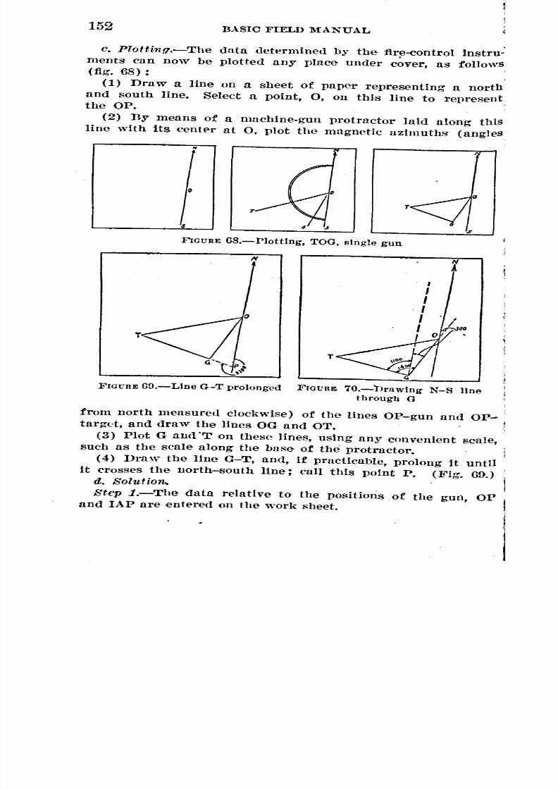
8/22/2019 Basic Field Manual Volume III-1932
http://slidepdf.com/reader/full/basic-field-manual-volume-iii-1932 158/203
BASIC FIELD MANUAL52
I
c. Plottillfl.-The data determined by the fir~-control instru-
ments can now be plotted any place under cover, as follows(fig. 68) :
(1) Draw a line on a sheet of paper representing a north
and south line. Select a point, 0, 011 this line to representthe OP.
(2) By means of a machine-gun protractor laid along this
line with its center at 0, plot the magnetic azimuths (angles'
i
I.
FIGURE 6B.-Plottlng, TOG, single gun
T
T
FIGUnE(In.-Line G-T
prolonged FlGunm 70.-DrawingN-S
linethrough G
frOIDnorth measured clockwise) of the lines OP-gun and OP-
targt.t, and draw the lines OG and OT.
(3) Plot G and'T on these lines, using any convenient scale,
such as the scale along the base of the protractor.
(4) Draw the line G-T, and, if practicable, prolong it until
it crosses the north-south line; call this point P. (Fig. 69.)d. Solution.
Step l.-The data relative to the positions of the g.un, OP
and lAP are entered on the work sheet.

8/22/2019 Basic Field Manual Volume III-1932
http://slidepdf.com/reader/full/basic-field-manual-volume-iii-1932 159/203
BASIC FIELD MANUAL 153
Step 2.-The- data obtained by instruments at the OP are
entered on the work sheet.
Step S.-The range, gun to target, is measured, using the same
seale as used to plot G and T. In this case it is 1,500 yards.
Step (fig. 71).-Assuming that the elevation of the gun is
any arbitrary figure (for convenience, 100 yards is usually
taken as the gun elevation), by means of the mil formula
determine the difference in elevation (vertical intervals) be-'
tween OP and gUll.
R X 1Il 1000 X (-30)
, TV 1.000 1,000 -30 yards
Since the OP Is above the gun, the elevation of the OP equals
100 plus 30 yards, or 130 yards.
o U.I~0Y"nl.
Et '"J"rd.Q ~~~"=:3I-
I~ / ITtl.90.9J""'la9Jyorcla
----1500/",.J' ...
FIGUUE 71.-Determining angle of site, G-T
In the same manner, figure the difference in eleYatioll of the
OP and target.
RXlIl la/lOX (-2~)TV=' 1,000 1,000 -39.1 yards
Sirl('e the target is below the OP the elevation is 130-39.1
or 90.9 yards. Since the elevation of the gun is 100 yards
(arbitrary) and that of the target is 90.9 yards, the vertical
interval, gun to target, is 100-90.9 yards equals minus 9.1 ~.ards
(the target being lower than the gun).
Step 5.-Using the mil formula, determine the angle of site.
gun.target:
M= 1000 TV 1000 X (-9.1)
H 1.500 6.1
(Minus hecause the target is below the gun.)
St(~P 6.-The next step is to obtain the QE. From Table I,
Fire-control Tables, the angle of elevation for 1,500 yards is
found to be 34.8 mils. Since the QE is the algebraic sum of the
98053°-32--11 .
~
---- ----
=
_ ' -
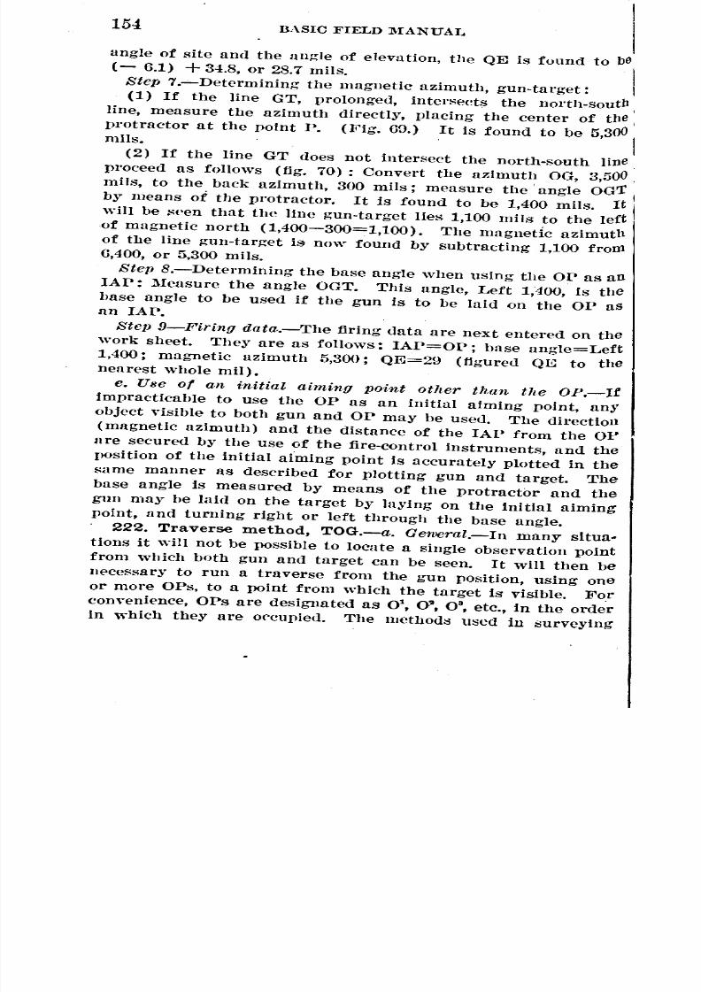
8/22/2019 Basic Field Manual Volume III-1932
http://slidepdf.com/reader/full/basic-field-manual-volume-iii-1932 160/203
154BASIC FIELD MANUAL
angle of site and the angle of elevation, the QE is found to be(- 6.1) +34.8, or 28.7 mils.Step 7.~Determining the magnetic azimuth, gun-target:
(1) If the line GT, prolonged, intersects the north-southline, measure the azimuth directly, placing the center of the
protractor at the point P. (Fig. 69.) It is found to be 5,300mils.
(2) If the line GT does not intersect the north-south line
proceed as follows (fig. 70) : Convert the azimuth OG, 3,500
mils, to the back azimuth, 300 mils; measure the. angle OG'!
by means of tIle protractor. It is found to be 1,400 mils. It
will be ~een that the line gun-target lies 1,100 mils to the left
of magnetic north (1,400-300=1,100). The magnetic azimuth
of the line gun-target is now found by subtracting 1,100 frow6,400, or 5,300 mils.
Step B.-Determining the base angle when using the OP as an
lAP: Measure the angle OGT. This angle, Left 1,400, is the
base angle to be used if the gun is to be laid on the OP asnn lAP.
Step 9-Firing data.-The firing data are next entered on the
work sheet. They are as follows: lAP=OP; base angle=Left
1,400; magnetic azimuth 5,300; QE=29 (figured QE to thenearest ,vhole mil).
e. Use of an initial aiming point other than the OP.-Ilimpracticable to use the OP as an initial aiming point, any
object visible to both gun and OP may be used. The direction
(magnetic azimuth) and the distance of the lAP from the OP
are secured by the use of the fire-control instruments, and the
position of the initial aiming point is accurately plotted in the
same manner as described for plotting gun and target. The
base angle is measured by means of the protractor and thegun may be laid on the target by laying on the initial aiming
point, and turning right or left through the base angle.
222. Traverse method, TOG.-a. GenlCral.-In many situa-
tions it will not be possible to locate a single observation point
from which both gun and target can be seen. Itwill then be
necessary to run a traverse from the gun position, using one
or more OPs, to a point from which the target is visible. Forconvenience, OPs are designated as Ot, O~,0 8, etc., in the order
in which they are occupied. The methods used in surveying

8/22/2019 Basic Field Manual Volume III-1932
http://slidepdf.com/reader/full/basic-field-manual-volume-iii-1932 161/203
BASIC FIELD l\IANUAL 155
are employed, data being obtained by the almmg circle, or
compass and angle-of-site instrument, and range finder.
, b. Obtaining data.-The officer who is to obtain the data
1lI0ves to a position 01
where he can see the target. 'Viththe aiming circle, or compass and angle-of-site instrument, the
tl1agnetic azimuth and angle of site from 01 to the target are
obtained. With the range finder he obtains the range. The
lJosition 01 is then marked by some means that will enable
him to locate it from his next position. He then moves to
some position where both 01 and the gun can be seen. His
Instruments are set up, and the range, magnetic azimuth, andangle of site from this position, 02 to 01 and to the gun are de-
termined. He then marks this position, 02 in such a manner
as to make it possible for the gun to lay on it as an lAP if
desirE'd. He can then go anywhere under cover, plot, and
calCUlate the data.
c. Plotting (fig. 72) .-The plotting is similar to that described
for the single or method. A north and south line is drawnat any convenient place on the paper. A point is made on this
line and markell 0\ The azimuths Ot-target and 01-02 (that
is the back azimuth of 0 2 to 0') are laid off. The position of
02 and the target are definitely located by laying off the ranges
on the lines drawn by means of some convenient scale, such as
the ~l<'aleon the base of the machine-gun protractor. 02 having
heen definitely located, a second north-and-south line is drawn
through 02 parallel to the north-and-south line through 0'.
1'he azimuth 02 to the gun is then lalU off and the position of
the gun is definitely located by laying off the range, 02_gun, as
above. The gun position and the target are then connected by
a line and the range gun-target determined by measuring the
line with the same scale.
d. Eleva.tion.-An arbitrary elevation (usually 100 :rards) is
given the gun position. The elevation of each successive point,
that is 02 0" anll target, is found with respect to the gun by
Using the mil formula. The difference in elevation of the gun
and target, or the VI in yards, may then be figured.
e. ])i.rcction.-The azimuth gun-target can be determined di-
rect from the plotted diagram by reading the azimuth of the
line at the intersection of either of the north-and-south lines.
'rhe hase angle can be read direct.
,
,

8/22/2019 Basic Field Manual Volume III-1932
http://slidepdf.com/reader/full/basic-field-manual-volume-iii-1932 162/203
156BASIC FIELD MANUAL
f. Firing data.-Firing data are figured in exactly the same
manner as previously described for the single OP method.
223. Mask clearance and troop safetY.-a. Oalculating clear-
ance from gUll position.-\Vhen the mask or frielHlly troops urc
NN
sFIGURE 72.-Plottlng. TOG, traverse method
visible from the gun, the clearance may be determined from the
gun position by computing the QE to the mask and subtracting
it from the QE to the target to see if the required clearance
exists; or, if the gun is already in position, the clearance may
be determined, without calculation, by using the sights on thegun.
~

8/22/2019 Basic Field Manual Volume III-1932
http://slidepdf.com/reader/full/basic-field-manual-volume-iii-1932 163/203
BASIC FIELD MANUAL 157
(1) Oomputin.g cleamncc from gun. position.-By the use
of the rang,e finder determine the range to the mask or friendly
troops. Find the angle of site to the mask or troops .. Know-
tng the range and angle of site, the QE' may be computed.
l'he clearance is determined as described under map methods
by subtracting the QE to the mask or troops from the QE to
the target. The clearance thus found must equal or exceed
the mask clearance, or safety angle, prescribed in Tables II
and III, Fire-control Tables.
(2) Deterrnining olearanoe by u/~eof rear si{Jht.-(a) 'Vhen
gun is already in position, to determine the clearance by thellse of the rear sight, lay the gun to hit the target. Then
Without moving the piece, set the sight at the corresponding
range for mask clearance (or troop safety) as given in Tables
II and III, Firp-control Tables. If the line of sighting thus
established clears the mask (or troops), it is practicable to fire.
(b) If no tables are available, the procedure is as follows:
If the range to the mask is less than 500 ~'ards, set the sightllt the range to the mask plus 425. If the line of sighting
thus established clears the mask, the cone of fire will clear.
If the range to the mask is 500 yards or greater, set the sightat the range to the mask plus 3()()and see if this line of sight- .
tng clears the mask. If there are friendly troops, the proce-
dure Is similar. The sight is set at the range to the troops
Dlus Gm, or at 1,525, whichever is the greater. This givesresults which are sufficiently accurate for all practical pur-
Doses.
b. When mask or troops are not visible from {Jun.-The range
and angle of site from an OP to the mask or troops are meas-
Ured and the QE to the mask or troops computed from these
data as before. Mask clearance and troop safety are then
determined in the usual manner.
SF:CTION VI
OBTAINING DATA WITHOUT A MAP FOR GUNS
GROUPI~D IN BATTERY
224. Procedure.-a. Obtaining data.-Elevation and direc-
tion data are obtained exactly as prescribed for the single-gun
Inethod, lising one or more OPs. Data to locate both flanks of
targets having width are recorded. Data to the positions of
Loth of the flank guns may he secured from the OP nearest the

8/22/2019 Basic Field Manual Volume III-1932
http://slidepdf.com/reader/full/basic-field-manual-volume-iii-1932 164/203
BASIC FIELD :MANUAL58
battery position and recorded for plotting; or data to thE' base
gun only, secured, and the position of the other flank gun of
the battery with reference to the base gun; that is, the magnetiC'
azimuth on which" the battery is to be placed and the relative
elevations of the flank guns, obtained for plotting.
b. The flank guns of the battery, ors, and targets (both
flanks of wide targets) are plotted to scale as described forsingle gun, TOG.
c. Tasks are then solved exactly as in the solution of a
map problem, except that vertical intervals are obtained asin single gun, TOG problems by means of the mil formula'instead of from map contours.
225. Hasty methods for distribution of fire.-a. When tJle
target front is approximately the same as the frontage of the
battery the direction data for the base gun only may be flgured
and all guns laid with this same direction, thus engaging the
target by parallel fire. The target may then be covered bytra versing the required amount.
b. When the target front is greater 01' less than that of
the battery, and speed is essential, direction data may be
figured as in a above and the target engaged by parallel cones.
This is a hasty method, and is wasteful of ammunition. It
should not be employed if sufficient time exists to figure
distribution of fire accurately.
SECTION VII
LAYn'G AND MAINTAINING LAYING
226. Direction and elevation.-Guns are always laill fordirection before being laid for elevation.
a. Dircction.-LaJing for direCtion is accomplished by meansof an aiming circle or compass, or by lAP and base angle, a~follows:
(1) Laying on base lines by means of an ai'11'l4ng circle or
compass.-(a) The aiming circle or compass is set up in any
Position with reference to the battery but not less than HiOyards from it. I
(b) All guns are ordered to lay on the head of the aimingcircles or compass, as an initial aiming point.
(c) The magnetic azimuth, aiming circle to base gun, is rentland converted to a back azimuth.
j
'
'

8/22/2019 Basic Field Manual Volume III-1932
http://slidepdf.com/reader/full/basic-field-manual-volume-iii-1932 165/203
BASIC FIELD MANUAL 159
(d) The difference between the magnetic azimuth of the base
line and the magnetic azimuth base gun-aiming circle is the
angle through which the base gun must turn from the aiming
('in'Ie in order to lay on its base line.
(e) The base gun is then turned through this angle as de-~crilJed in battery drill.
!<IOURlD 73.-Paralleling guns by means of aiming circle or compass
(f) To lay the other guns of the battery, this procedure is re-
peat(!d for each gun. This automatically parallels all guns of
the hattery .. (Fig. 73.)
(2) Laying by means of an lAP and base angle.-(a) When
the huttery angle of parallax has been determined from a map-
1. The guns are all laid on the lAP with their dials andrear sights set at zero.

8/22/2019 Basic Field Manual Volume III-1932
http://slidepdf.com/reader/full/basic-field-manual-volume-iii-1932 166/203
160 BASIC FIELD MANUAL
f. The amount each gun must turn nway from the base
gun in order to he varnllel is determined as de-"scribed in paragraph 215 h.
3. All guns being pa)'allel, they are then swung through
the base angle (fig. m) by means of the gradna tions
on the dial and }'£>l1rsight. They are then laid
for direction.
(b) 'Vhen the hattery angle of parallax: has not he('n <1e-
termineu from a map--
1. Each flank gun is llIo11llted and laid on the front sight
of the other.
2. ~'he traversing dials and f('ar sigllts are set at zero.
S. They are then laiu Upon the initial aiming point, and
the <lial and fear sights at'e read, thereby deter-
mining the nngle tllrough which they have moved.
~' The sum of these angles subtracted from 3,200 mils
will give the required battery angle of parallax:(fig. 74) : 1,OGO+2,llO=3,lGO. 3,200-3,lGO=40 (bat-
tery angle of parallax).
5. The guns are then paralleled and tUrJwd through the
base angle as described above.
(c) The mechanics of these methods are covereu in batterydrill.
(3) (a) La.yinf} by means Of lAP visible only to base f}un.-The base gun is laid on the lAP and moved to its base line
as expIahwd above.
(b) The traYersing dial and rt'ar sight of the base gnn re set
at zero. The hase gun is then turnpd through the angle ABC
(fig. 75) and laid on the other guns in turn, measuring the
angle ABC by means of the traversing dial anll rear sight.
Each of the other gur.s lays on the base gun with the traversing
dial set at zero. (\Vhenever guJlS lay on each other, each gun-
ner aims at the f"ont sight of the other gun.)
(0) The angle from the base gun through which the other
guns must turn in order to lIe laid parallel to the base line of
the base gun (:\0. 1 in this case) is the 'angle BCD.
Example: Assume that the angle ABC is 1,700 mils. Thpn
the angle BCD is tile differenee between 3,200 mils and 1,700
mils, and equals 1,GOO mils. The other gun then turns from
the base guu toward its own base line and sets off the angle
_

8/22/2019 Basic Field Manual Volume III-1932
http://slidepdf.com/reader/full/basic-field-manual-volume-iii-1932 167/203
BASIC FIELD :MANUAL 161
:BCD (1,500 mils in this case). It is then parallel to the base
line of the base gun. This method is known as reciprocal lay-
il lg• Any gun lllay be used as the base gun in thIs operation.
lAP
\
\
\
\\
\
\\
\
\\\
\
\
\\
\\
\\
\\
\\\\\
1
FIGURIII H.-Determining battery angle of paral-
lax by means of flank guns
~nstead ot employing an lAP the base gun may be laid by aim-ll.gcircle or compass and the other guns by reciprocal laying.
b. Elevation.-Guns are laid for elevation by means of clin-
tneterl'4. QEs are Het on the instruments, and the latter :IreIlaced on the right-side plate of the gun; arc to the rear if the
!,IJ:: is positive and arc to the front if the QE is negative.
~
~ ~
8/22/2019 Basic Field Manual Volume III-1932
http://slidepdf.com/reader/full/basic-field-manual-volume-iii-1932 168/203
lG2 llASIO nEW ~IANUAL
227. Laying guns under cover of darkness.-When the gu
are brought into position for the first time at night the folIo«'
ing arrangements should be made during the day:, , ':
a. Drive a stake at the point where each gun is to be mounted
The stake should be of such height that the tripod may
mounted over it without disturbing the stake.
b. The necessary direction a11(lelevation data are obtaine.
by a suitable indirect-laying method.
c. Base and aiming stakes are set out by mounting an aimin'.drde in succession over each gun stake and measuring off
required azimuths.
l ~
/
///
/
///
/
'///
..........
'\\
C 1500
"FIGURE 75.-Lnying on base lines by menns of an lAP
Ylslble only to base gun
d. The g,uns are brought up and mounted over the
Luminous marks are placed on the base and aiming
which were set out during the day. A covered flashlight, 0lf
match, is used to set and level the clinometer.228. Maintaining laying; procedure.-a. To maintain lut
ing, base stakes (for base lines) and aimIng stakes (fof taSk')
are set out about 20 yards in front of the gun. The gunnef
must be careful to set his sights at 2,OO()before lining in all
stake. The sight should be left at this elevation, and the gUJJJner should check his direction frequently during firing.
b. From time to time, as between bursts or when changiIl~
a belt, the corporal checks the elevation by the clinometer. 11e
also checks the direction by means of the traversing, dial.
o. In order to minimize movement of the gun during firing,T bases, or an iplprovised foundation of logs or timber, should
n
.
b
th
stakes.
stakes,
.
,

8/22/2019 Basic Field Manual Volume III-1932
http://slidepdf.com/reader/full/basic-field-manual-volume-iii-1932 169/203
BASIC FIELD MANUAL 163
be used with sandbags laid on the logs. Jamming handles
8hould be tight.
SECTION VIII
SEARCHING REVERS1<] SLOPES
229. General.-Searching reverse slopes is that form of fire
In which the bullets fall at such an angle to the slope of the
ground that grazing fire is produced. If reverse slopes had no
Inequalities or shell holes the maximum result would be
Obtainpdwhen the fall of the bullet was exactly parallel to the
ground; but since inequalities always exist, tIle best results
IVin be obtained when the angle of impact (the angle which
the trajectory makes with the slope of the ground at the point
Of imll:tct) is aPlH'oximately 45 mils. Any angle of impact
between 30' and GO mils will give excellent results, and good
results will be obtained with an angle of impact between 15 and
/(; mils. Data for such firing must ordinarily be obtained from
the map, although in exceptional cases the data may be secured
by TOG methods from an observation point. .
230. Determining the slope of the ground.-Scale the dis-
tance hetween two contours at extremities of the slope to be
/8earchcd. Using this distance, in yards, as R; and the VI be-
t'''een these contours, also in yards, as lV, substitute in the
h, lV X 1000 ..'lJil fOl'mula,M=-----
it
Exa1'n,ple.-The distanc:e bet,,;een two selected contours on the
~lol1eto be sCtil'ched seales 200 yards, and the VI between them
as Shown on the lIlap is 3G feet or 12 yards.' ,. lV X 1000' .
1Jf=--R--
1J f 12 X 1000
200M equals GO mils. (The slope of the ground.)
231. Finding the best position from which to search a re-
~erse slope.-a. By computation.-(l) Measure the angle of
~Iopeof the ground at the target and to this angle add 45 mils.
~ind the range which has an angle of fall corresponding to
this sum. On the map measure back this distance from the
target. If the position thus found is on the same level with thetarget, It is a suitable position.
(2) If the target is above or below this position, measure the
lingle of site and subtract it from or add it to 45 as the angle of
=

8/22/2019 Basic Field Manual Volume III-1932
http://slidepdf.com/reader/full/basic-field-manual-volume-iii-1932 170/203
164- BASIC FIELD MANUAL
site is positiYe or negative. If the result is bet\yeen 15 and 75,
the position is suHable.
(3) If the resul t is greater than 75, move forward 100 yardS;
if less than 15, move back 100 yards and compute the angleof impact from the new position. Continue until a positioil
is found from which the angle of imr1act is Qetween 15 and
75 mils, preferably between 30 and GOmils.
(4) If impracticable to move the gun back and forth, 11
lateral moyement of the gun, keeping it at the same distanCe
from the target, may result in a sufficient change ill the angle;
j1100 1100 IbOO 1+00 1500 If>OO ITOO \600 1900 200~
RA/'IGf. lit YAIlO~
FIGURE 76.-Use 01' profiles anu graphs
of site to secure the de!Sired result. Thus when the gun is oIl
the side of a hill, a movement up or down the hill will change
the angle of the site without changing the range. ' .
b. By table.-See Table VI, Fire-control Tables.
232. Use of profiles and graphs.-To determine the possI'
hilith's for searching reverse sloves a profile is made to thesame scale as the trajectory chart (horizontally and verticallY)
on transparent paper. Place the profile of the ground over
the trajectory chart with the gun point of the chart on the
snrface of the ground as indicated by the profile. Move the
profile about, keeping the gun point of the chart on the profile
line and keeping the horizontal line of the profi.le parallel tOl-.
the horizontal lines of the chart, until a point is found wherethe trajectories strike the reverse slope at an angle greater
than the slope of the ground. Mark this point on the profile.
Referring back to the map from which the profile was made
the point is located. (Fig. 76.)
~

8/22/2019 Basic Field Manual Volume III-1932
http://slidepdf.com/reader/full/basic-field-manual-volume-iii-1932 171/203
BASIC FIELD MANUAL
SECTION IX
DEFILADED FIRING rOSITIOXS
165
233. General.-a. Guns in firing positions on reverse slopes~rnploy direct or indirect laying depending upon the amount
Of defilade, tlle distance of the guns from the crest and
''"hether or Bot the target is visible from the crest. Thera
ar~ three cases:
(1) When the targpt is visihle from the crest and there is
~ight defilade only; that is, tIle line of sight is not defiladecl.
but all ()ther parts of the gun below the line of sight are(!eftlad('d.
(2) When the target is visible from the crest, the gun hav-
ing a greHtel' degn'e of' defilade than in (1) above and the
target can be spen by observer from some position in the
"icinity of the gun.
(3) When the target is not visible from the crest.
b. In the first ease direct laying is employed. In the lasttwo indirect laying is necessary. There is nothing new to
llt'escrihe in delivering fire from defiladed positions falling
\\'ithin case (1) or case (3), the former being purely direct
Ia.Sing and the latter indirect la,ying. Howeyer, the use of
llositions falling withi'n case (2) requires special consideration
!l~ the lllethods to l)e employed partake of the nature of direct
Ia.Ying,since dire('tion is established without the use of in-~truments, ~nd observation and adjustment of fire are made
hy the ohserver from positions near the gun.
c. 'l'he firing from positions falling under case (1) is known
a~ "sight d(>filade," while those falling under case (2) are
,knownliS "position defilade."
234. Position defilade.-a. A..drantagcs.-GUl1S in position
l!('filade fire" mnsked from ground observation and dirf'Ct fire.Generally the mask is sufficient to hide the smoke and flash.
~tovenH'nts in the vieinity of the guns are more or less un-
~~stricted and hence the problems of control and supply ara
~reatIy simplified. Normally guns can go into action much
ll.liCker,and with "less fatigue on the part of the gun crew,
i;ing POl'1itiondefilade than by ul'1ingany other position. This
e.<;pe<'lllllyrue when the Matthews cart is uf;ed.
b. Dilwd)vanfa"gcft.-The fire of guns in position defilade is
l'Ucticully ineffective against rapidly m"oving targets and tar-
~ ~

8/22/2019 Basic Field Manual Volume III-1932
http://slidepdf.com/reader/full/basic-field-manual-volume-iii-1932 172/203
I
I
166 BASIC FIELD MANUAL'
~ets at close range, or with a' lal:ge negative angle of site.
Also, in order to lay on final protective lines, they must change
position.
c. Procedure.-The method of firing from position defilade
can best be illustrated by means of a problem. To facilitate
following this problem, refer to FigUr~77.
(1) A Problem (fig. 77).- (a) The section leader moves to
a position on the reverse slope where he can see the target.
lIe signals the squan leaders to join him,' ar.d while they afC
moving forward he determines the angle of site by means of
the angle-of-site instrument, and the target width by means
of the mil scale in the field glasses. lie finds the AS to be
plus 2 and the target width in n1i1s'to be 30. If friendly trooPS
are between his guns and the target, 'he detennines safety b1
applying the "leader's rule" from a position on the crest of
the hill, the reverse slope of which is occupied by his guns ill
position defilade. 'Vhen the corporals report he designates tb
e
target, obtains the range by estimation, taking the mean of tbe
('orporals' estimation and his own. lIe determines the range to
he 830 yards. lIe 'obtains the angle ..of elevation by referenCe
to Table I, Fire-control Tables; and' then' determines the Q1!J.lIe points out' the approximate locations for each gun, based
jn his knowledge of the QE, and gives bis fire order:
QE: PIus 13. .No.1: Traverse Left 20. . .
No.2: Traverse Right 20. .
At my signal.. .,.
( b) The corporals signal their squads forward, move to tbe
vicinity of the designated locations and select definite posl,
tions in position defilade. They use the cleaning rod,
on the toe of' the shoe with chin resting on the handle,' todetermine tbeheight of the gunner's eyes .. lIaving selectetf
definite positions they mark them by sticking the cleaning
in the ground. .
(c) Upon arrival of the guns the corporals lay them fot.
direction, by standing in rear, and com.manding "aiming stal\C
out." It may be necessary in some cases for the corporal~
to stand on several ammunition boxes' in order to lay theit
guns for uirection, or even resort to the method of two
servers, some distance apart, establishing the line by altef
nately dtrectin~ each' other Into line with gnn and target
.
.
'
plaCe(!
rotl
ob
'

8/22/2019 Basic Field Manual Volume III-1932
http://slidepdf.com/reader/full/basic-field-manual-volume-iii-1932 173/203
------------ ------ .. -- ---~- ------ -~- - ----
W~I H T ll £ ~ rC TI OH l EA Il iR l IS N O T AT 'IlE
G II /I I P OS IT IO N, AS " NOW" I4ERE,HI DITERMINES
TU' A.'-(G-T)BY SlUCT'NG APOINT AS FA.AI' &O Vl , T Il~ T A~ GE T A Eo l iE I 5A DO V~ Y Il E G UN .
Itll: ~~OAT 850
A.S,. DITliIlf'l'"O 10 !Ii tA
~-:::~~~O~OI)ASME WAIO"S DURSt' TO~SIUlClT
(Face p. 166.) .

8/22/2019 Basic Field Manual Volume III-1932
http://slidepdf.com/reader/full/basic-field-manual-volume-iii-1932 174/203
:!lASIC FIELD :MANUAL -167.
i'they_then place the QE .?R.. their guns and the gunners chec~k
e1earauce. .,>:
I(d) 'rIle gunners check clearance by sighting along .the
'''a tel' jacket, on line with the bore. .If time permits, th("
hOlt mny be removed and clearance determined by sighting
through the bore. If, clearance exists the Nos.. 2 signal
;I, :Ready." If clearance does not exist, the corporals move
the guns forward until clearance does exist;, but if prac-
ticable, not so far forward that the guns go out of position
lletilade. _,
(e) I,'ire is then controlled either by the section leader
{ll.the squad leaders.
(f) Where speed is an important factor, the section leader
Inny estimate the range, the angle of site (if the angle of siteIs small), and target width in mils (if his fingers are cali-
hr~ted). As his guns are moving forward he selects positions
for each. As each' gun arrives, he issues his fire order 'and
layS it for direction. .IIis 'fire order would -he:
. '{QE: Plus 13..~o. 1 gun Tra-yerse Lef.t _~.
. C?mn~enc~ ~ring. ,
{
QE: Plus'13.
NO.2 gun Traverse Rigbt 20.
o ,Commence firing. ,
'J'he sertion leader then would .adjust the fire of both guns.
'(2) New taruets.-Wlieri new targets appear the guns may be
khifted through ~heir respective angles of shift by commands
from the section leader (corporals are trained to zero their
dials and sights' on .the ;'fi~st aiming stake set out) who de-
termirlPs the angle by means of his field glasses, sitogoni-
Otneter, or calibrated fingers. The additional or reduc~d ele-
a.Uon required is estimated.
(3) Ob'8ervation and adjustment of fire.-In firing from po-
k1tion defilade, it is often desirable to get off the first burst
l\!ij quiekly' as possible and then adjust. If speed is demanded,
the accnrate determination of the QE and direction is not es-<'entia!. Observation of fire may be greatly increased by load-
Ilg belts with tracers. Generally one tracer to nine solid ball
suffielent. In situations where time is available, it is ob-
lous that accurate data ne('es.~ary to engage many targets, or
~
"
' -
~
~

8/22/2019 Basic Field Manual Volume III-1932
http://slidepdf.com/reader/full/basic-field-manual-volume-iii-1932 175/203
168 • BASIC FIELD MANUAL
possible targets, can be Qbtained and guns camouflaged so as
to make them safe from all observation.
(4) The platoon as a batterll.-Platoons may use this methOdas a unit, controlled as a battery. Elevation is determined fot
one gun and applied to all. Direction is established, by tbe
platoon or section leaders, for all targets by quickly aligning
each gun on its approximate part of the target and causing aiJll'
ing stakes to be set out. Guns do not have to be paralleled as
in other methods of indirect laying nor is it necessary to de-
termine the battery angle of distribution or convergence. Ad'justment of fire can be made either by the platoon leader or
by the section leaders for their respective sections.. New tat'
gets appearing within the sector can be engaged quickly as
described above.
SECTION X
TRAINING O~ LANDSCAPE TARGETS AT 1,000 INCH ANlJ. AT UNKNOWN SnORT RANGES
235. Battery firing on 1,OOO-inch range.-a. General../
Battery firing on the 1,OOO-inchange instructs an organizatioO
and tests its efficiency in battery drill. In addition, it illustrateS
most of the technique of indirect laying and permits the gunnerS
to see the results of their firing, which is usually impossible 10
field firing. It should be used for instruction purposes prior to
battery firing in the field, as it requires a much smaller ammunl
tion expenditure. It should not replace battery firing in tlJe
field, however, except when lack of available terrain precludeS
field firing.b. Procedure.-(l) Target.~.-The targets used are the stanO'
ard Series A landscapes issued by the Ordnance
The method of setting up the targets is shown in Figure 78. JO
order-to economize in the expenditure of the upper panels Whiel
are the panels fired on, mimeographed reproductions of seleete
targets may be prepared and fastened over the proper target'
before each firing. .
(2) Mounting UU11.~.-Theguns are mounted on T bases se
flush with the top of the firing points. In order to permit fotliguns to fire on the same set of targets, the right T base shoUI
be opposite the first or second panel from the right and all 1bases should be as close together as possible. The guns at
laid with a clfnometer setting of •.ero, and then leveled
DepartmeJ}
'

8/22/2019 Basic Field Manual Volume III-1932
http://slidepdf.com/reader/full/basic-field-manual-volume-iii-1932 176/203

8/22/2019 Basic Field Manual Volume III-1932
http://slidepdf.com/reader/full/basic-field-manual-volume-iii-1932 177/203
170 . BASIC FIELD l\IANUAL
accurately as' pOssible by raising or lowering T bases as
required. !
(3) Targeting and obtaining "zel'o" quadrant elevations.-
The guns are targeted as for machine-gun mar~rsmanship, the
blank 1'0. 1 panel. LJeingtised for this purIJ{lse. All guns, hav~
ing been targeted, are laid with a sight setting of 441 ~!ards 011
an aiming point on the No.1 blank panel, which is on appro:x:i~
mately the same level as tIle gun muzzles. The elevations of the
guns with respect to the. horizontal are then read by means of
a clinometer, and these quadrant elevations are used for the
firing as the "zero". quadrant. elevations of the respectiveguns. For example, assume that it is desired to fire at a
point which is 8' inches higher on the landscape targets thanthe ahning point' '~~e'dto obtain the" zero" quadrant elevations.
The QE announcE'd in the fire order would be plm; 8 (an inch
at 1,000 inches LJeingequivalent to 1 mil). Assume also that
the" zero" qua(lr~ntelenlti()ns det~rmined as described above
for the four gnns we're No.\i b'Uh, 0; No.2 gun, pIns 2; No.3gun, minus 1; and Ko. 4 gun, minus 4. Since respective gunnersmust layoff plus 8 mils from, thetr '.'zero" quadrant elevations,
No.1 gunner .would set off QE plus 8; No.2, plus 10; No.3 gun,
plus 7; and No.4 gun, plus 4., '!l:c,
(4) Preparing 'd(J~a .for firi~g <t;;problem.-The officer in
charge of the firing must 'select sui fable targets and prepare
certain data ..for firing. The first, step is to determine the
magnetic azirriut]l 'of bas(! line; that is, the magnetic azimuth
of the line; base gun. (usually NO.1 gun) to its fl:ink of the
principal target., This magnetic azimuth is read direct by meanS
of an aiming~circlemotinted over the T base of the base gUll
before the guns ate emplaced.: A compass may be used if all
aiming circle i's'riot available. The target front of each target
and angles 'of' shift are likewise measured with the aiming
circle. The quadriu'lt elevations of the flank guns for each
target are o.btainedwith the aiming circle by measuring the
vertical angles 1>etwee'nhe aiming POi~t used for obtaining zerO
quadrant elevations ahd the respective flanks of the target.
The data rela"tive to target fronts, angles of shift, and quadrant
elevations of flank guns for each target may be obtained bymeasuring the distances in inches with a steel tape if desired,
or if no aiming circle is available., The guns having been
mounted, the battery front in mils is obtained by measuring the

8/22/2019 Basic Field Manual Volume III-1932
http://slidepdf.com/reader/full/basic-field-manual-volume-iii-1932 178/203
BASIO FIELD l\:lANUAL171
distance in inches between the pintles of the No. 1 and No. 4
gUns.
NOTF..-These data would be obtained by plotting and calculation in
the normal service map or TOG problem.
c. A typical problem,.-Assume that it is desired to fire on
the targets indicated as '.rask A and Task B (fig. 78), and that
the following data have been prepared:
No.1 base gun; battery front 160 mils.
Base lines on Task A.:Magnetic aziml'lth, base lines equals 2,505 mils.
Ta,<l!c A:Target front equals 48 mils.
QliJ,all guns plUS 7 mils.
7'olollc B:
Angle of shift, equals Right 52.
,.rurget front, equals 25 mils.
QliJNo.1 gun, equals plus 13 mils.
Qg No.4 gun, equals plus 7 mils.'rhe panels are now covered with burlap screens and the
data are applied to the guns in the following manner: The guns
are laid on their base lines, using the aiming circle as an lAP
as dpscribed in paragraph 226 a (1). "Base pastel's," ordi-
nary black pastel's, are placed on th~ screen by Nos. 3 for
each bruno The gunners line-in these pastel's, using a sight set-
ting of 441 yards and the zero quadrant elevations. The bat-
tery front being 160 mils and '.rask A having a frontage of 48
mils, the battery angle of convergence for Task A is 160-48,
or 112 mils, and the gun :mgle of convergence is 37 mils. The
offieer in charge of firing therefore establishes aiming marks
Which are made on the burlap screen for each gun by No. 3
who Is lined in by the gunner. These marks are used instead
of aiming stakes and by the following command:
All guns on base pasters.
No.2, dial Right 20, sight Left 17.
No.3, dial Right 60, sight Left 14.
No.4, dial Right 100, sight Left 12.
Red aiming marks out.
Aiming marks are now established on the screen for Task B,
the commllnd to accomplish this combining the angle of shift,
Hight 52, with the gun angles of convergence for Task H, 45
j

8/22/2019 Basic Field Manual Volume III-1932
http://slidepdf.com/reader/full/basic-field-manual-volume-iii-1932 179/203
172 BASIC FIELD MANUAL
mils (one-third of 135, the difference between the battery ft'ont
and the frontage of Task B), in the following manner:
All guns on base lines.
No.1, dial Right 40, sight Left 12.
No.2, dial Right 80, sight Left 17.
No.3, dial Right 140, sight Left 2.
No.4, dial Right 180, sight Left 7.
Blue aiming marks out.
Since the targets are so much smaller than the ground tar-
gets they represent, the guns are fired at the figured. quadrant
elevations r{'duced by only 1 mil with a search up of 2 milsand just enough traverse to have each gun cover one-third of
the target front. Gunners are instructed to fire bursts of five.
On this basis the commands for engaging Tasks A and Bare
as follows:
Ta.sk ..4..:
Lay on red aiming marks.
All guns QE plus 6.Traverse 12.
Search up 2.
At my signal.
Commence firing.
Task B:
Lay on blue aiming marks.
No.1 QE plus 12.No.2 QE plus 10.
No.3 QE plus 8.
No.4 QE plus 6.
Trallerse 8.
Search up 2.
At my signal.
Commence firing.
Upon completion of the firing, the screens are removed, the
results of the firing shown to all the men, and a thorough
('ritique given.
236. TOGproblems at unknown short ranges.-Single gun
and battery TOG problems may be conducted at unknown short
ranges on landscape targets. The problems may be solvedeither outdoors or indoors, and the accuracy of firing data
may be checked either with or without firing.

8/22/2019 Basic Field Manual Volume III-1932
http://slidepdf.com/reader/full/basic-field-manual-volume-iii-1932 180/203
BASIC FIELD :MANUAL 173
a. The set-u.p.-The landscape targets are used in the same
l1anner as on the 1,OOO-inchrange. A single gun or a bat-
ery is mounted on T bases at a convenient distance from the
argets as described for 1,OOO-inchiring. Additional landscapearget panels are placed between the guns and the target to
epresent friendly troops or mask or both.
b. Solution. of the 1J1'oblcm.-The targf't, mask or friendly
troops or both as desired, and one or more OPs having been
designated, data are obtained exactly as for a TOG problem
in the field except that a tape measure is used instead of a
range finder for measuring ranges, and all ranges are con-\>erted to yards by the use of any convenient range scale such.
!ls 1 inch equals 1 :rard. Angles of site from OP to the gun
or guns are measured to the bolt handle or to the approximate
height of a cartridge in the ('hamber. Data are plotted, fir-
ing data figured, and guns laid for direction and elevation,
e:x:actlyas for a problem in the field.
c. Ohecking solutiorl-8 without firing.-Guns having been laid
for direction and elevation, rear sights are run up to the cor-
responding ranges for mask clearance or troop safety and
Clearance and safety are checked by means of the line of sight-
ing. The panels representing; mask and friendly troops are re-
lUoved,and rear sights are set at the ranges to the target and
direction and elevation checked by looking through the sights.
d;. 01wcking 8oluHon8 b1l firing.-To fire the problem the guu
Or guns are laid for direction as for a TOG problem in the
lleld, and for elevation using figured angles of site only instead
Of quadrant elevations, the fall of the bullet for the short
ranges being so slight that it may be disr('garded.
SECTION XI
TESTS OF TRAINING IN INDIRECT LAYING
237. Purpose.-Tests of training in indirect laying will be
held for the purpose of determining the proficiency of machine-
gun units in the technique of indirect laying. .
238. Units required to fire.-Units equipped with machine
guns as a principal weapon are required to undergo the tests.
No unit larger than a platoon will be tested. The tests will
Consist of a problem or series of problems to be fired by one or
hoth Hcctions of the platoon.

8/22/2019 Basic Field Manual Volume III-1932
http://slidepdf.com/reader/full/basic-field-manual-volume-iii-1932 181/203
174 BASIC FIELD MANUAL
239. When held.-The tests will be held after a course of nt
least one week's instruction in indirect laying.
240. By whom conducted.-The tests will be conducted bY
an officer designated by the commanding officer of the regiment
or separate battalion.
241. Ranges.-Whenever practicable the tests of training
will be held on ground with which the troops undergoing tM
test are unfamiliar. 'Vhen terrain is not available for firing test
problems in the field, the tests may be conducted on the 1,000
inch range by means of landscape targets.
242. Rules.-The officer ordering the tests will prescribe
~uch rules as he deems appropriate to suit local conditions .•. 243. Procedure.-T11e tests will be figured and fired under
the direction and supervision of the officer ordered to conduct
them. No prior information will be furnished the unit under-
going the tests other than the time and place of reporting.
244. Results.-A careful record of the results of the testS
will be kept. A written report will be transmitted by the officer
conducting the tests to the officer ordering them. No ratingwill be made. The officer conducting the tests will, however,
mention special point~ of excellence or defects noted.
-

8/22/2019 Basic Field Manual Volume III-1932
http://slidepdf.com/reader/full/basic-field-manual-volume-iii-1932 182/203
CHAPTER 5
BARRAGES AND CONCENTRATIONS
,. 245. General.-In principle, guns within range of an enemy
should be ready and able to fire effectively upon designated tar-
gets. The machine guns lvithin an area fall naturally into two
classes: those in direct support of front line units, and those
forming a part of reserve battalions. The fire power of guns of
reserve battalions, guns which might otherwise be silent, should
he utilized whenever possible, in conjunction with the fire power
of maclline guns of assault battalions and of other supporting
weapons to fire barrages and concentrations: this accurate
and dense fire can be placed upon any point, line, or 1!-reawithin
range of the guns unless masked by an obstruction or by therequirement for t]le safety of friendly troops. In order that
the fire of machine guns and other supporting weapons from
severlll units may be properly coordinated for firing barrages
and ('oncentrntions it is usually necessary to place such firing
Under the dIrect control of one officer. The order designating
an officer to organize, control, and coordinate barrage and
eoncentrntion fire should include the units to participate, thefire missions, and the general locations from which units will
llellvt:>rtheir fire. This chapter covers the uses of barrages
and ('oncentrations, and the manner in which this fire is de-
veloped when ordered by a commander.
246. Barrages defined.-a. A machine-gun barrage is a bar-
rier of fire consisting of the organized, controlled, and co-
ordinated fire of several guns which are usually arranged inbatteries of two or more guns each. The beaten zones of
these guns are laid down on a line, or series of lines, to deny
the enemy a passage through the area of fire. The whole line
having been designated, it is then divided into sections of appro-
llriate size an(1 allotted to each battery available for. the
mission. Barrages may be moving (rolling) or stationary
(standing) ; they may be used offensively or defensively. The
175

8/22/2019 Basic Field Manual Volume III-1932
http://slidepdf.com/reader/full/basic-field-manual-volume-iii-1932 183/203
176 BASIC FIELD MANUAL
delivery of fire may be by direct laying, by indirect laying,
or by a combination of both, depending upon the type of fire
which is most suitable for the mission to be performed.
b. A normal barrage is the barrage of primary importance
for which each battery is laid at all times except when actuallY'engaged upon other missions. This fire is usually delivered
close to friendly troops to screen and protect them by inflicting
losses on the enemy, and by keeping down or preventing his
fire. '.rhe line to be covered by fire should be placed as close
to the friendly troops as the requirements of safety. and the
selection of suitable ground will permit. Fire is <lelivered at
once upon call, usually by signal from the appropriate area.It is the barrage usually fired during an enemy assault~
o. In a box barrage the fire is applied to two or more sidesof a position in such a way as to isolate it. It is generallY
used to cover raids on enemy positions. \Vhen used in con-
junction with artIllery, machine guns may be employed to
place a standing barrage on one or more sides of the box, or
to thicken the entire artillery box barrage. It is a form ofthe standing barrage.
d. A rolling barrage is fire appU('d progressively in distance
at indicated intervals of time to successive lines. It is a forDl
of accompanying fire seldom practicable for machine guns. This
is due to the impossibility of searching many reverse slopes
and the difficult problem of clearance of friendly troops on all
lines that a rolling barrage may reach. Lifts by machine gunsare made from 200 to 500 yards at a time, ('ach lift being cal-
culated as a new task and not determined from the data for
the first firing. 'Vhen machine guns are employed with other
weapons their fire is placed approximately 400 yards ahead
of the nearest line of light artillery high explosive shells.

8/22/2019 Basic Field Manual Volume III-1932
http://slidepdf.com/reader/full/basic-field-manual-volume-iii-1932 184/203
BASIC FIELD MANUAL 177
247. Concentrations de:fi.ned.-A concentration of machine-
gun fire consists of the organized, controlled, and coordinated
fire of several guns, usually arranged in batteries, for the pur-
pose of neutralizing or demoralizing an area known or thoughtto be occupied by the enemy. This definition of a concentration
::
=
;;
:FlGURID 79.-l\Iacbine-gull normal barrage
must be borne in mind in contradistinction to barrage fire in
whleh each gun and each battery have a section of the entireline as a separate task upon which they fire to deny the ground
under fire to the enemy.248. Organization of guns.-a. Best results can obtain only
when the guns available for barrage and concentration missions
8/22/2019 Basic Field Manual Volume III-1932
http://slidepdf.com/reader/full/basic-field-manual-volume-iii-1932 185/203
178 BASIC FIELD MANUAL
are .organized as a whole and their fire directed in accordance
with a general plan. Time permitting, the guns which must
employ indirect laying methods are organized into batterieS
FIGURE 80.-Machine-gun box barrage
of two, three, or four guns each, the platoon of four gunsbeing the usual battery. Batteries within a group are lettered
from right to left. Two or more batteries constitute 11 group,

8/22/2019 Basic Field Manual Volume III-1932
http://slidepdf.com/reader/full/basic-field-manual-volume-iii-1932 186/203
BASIC FIELD MANUAL 179
the company being the usual' group, the company commander
being the group commander. Groups are numbered from right
to left. Two or more groups may constitute a separate com-
mand. The plan need not follow definite lines of organiza-tion. Its most essential features are contrul and flexibility.
Th~ organization is of a flexible nature created on the spot and
1esigned for very definite tasks and missions.
FIGunE 81.--=-l\lachlne-gun concentration
b. The organization for the purpose of firing concentrations
and barrages is brought about by the commander who designates
the fire missions to be engaged, the unit~ to engage them, and,
in f4(>mecases, the positions which units will occupy. In the
usuul case he will also designate an officer to perform the neces-
sary duties in connection with organization, coordination, and
control. Time permitting, this information can be disseminated
by the use of an organization chart. (Par. 252.) However,

8/22/2019 Basic Field Manual Volume III-1932
http://slidepdf.com/reader/full/basic-field-manual-volume-iii-1932 187/203
180 BASIC FIELD MANUAL
where speed is a primary con8ideration it may be built up as
time proceeds. (Par. 251.)
c. The duties of this officer are as follows:
(1) To organize the guns available into. batteries and groupS.
(2) To designate approximate positions for each group.(3) To designate fire missions for each group in accordWlce
with the tactical plan.
(4) To assure an adequate supply of ammunition and arrangefor its distribution.
(5) To provide for communication and control.
(6) To maintain contact with the troops supported, his unit
commander, as well as his batteries and groups.d. The duties of the group commander are as follows:
(1) To designate positions for each battery.
(2) To prescribe the fire missions for each battery.
(3) To carry out the plans for ammunition supply, communi-('ation, and control.
(4) To maintain contact with the troops supported, the bar-
rage commander, and each battery.e. The duties of the. ba ttery commanders are as follows:
(1) To compute the fire data for his battery.
(2) To prepare battery and gun charts.
(3) To supervise and conduct the fire of the battery, taking
all precautions necessary to provide clearance over friendlytroops.
(4) To arrange for observation and adjustment of fire when-ever such action Is possible.
249. Coordination.-a. Maximum efficiency results only
where there is eomplete coordilla tion betwpen aU- the guns of
an area, and with the guns of adjacent areas .. Further, the
fire of all weapons must be coordinated, the most effective use
being exacted of each. The fire of the artillery, of the Infan-
try mortar, the final protective lines of front area guns, as
well as the guns assigned to barrage and concentration fire
missions, must all be considered as one problem. Hasty or-
ganization can not, of course, permit all of these factors, but
time permitting they are vital considerations.
b. In an organization involving a number of batteries, the
placing of all guns on identical fire missions would be unwise;
it would restrict the number of tasks too greatly because only

8/22/2019 Basic Field Manual Volume III-1932
http://slidepdf.com/reader/full/basic-field-manual-volume-iii-1932 188/203
t
BASIC FIELD :MANUAL 181
a small number of tasks should be assigned to each battery,
and it would be wasteful of ammunition. Targets which may
be engaged by frontal fire by one battery may be engaged by
oblique, or even enfilade, fire by another; some batteries will
be able to fire more effectivelY upon certain tasks than others.
All of these factors must be considered in building up and
llerfedlng the plan.250. Control.-a. General.-The dominant factor in barrage
fire is control. Unless the commander has the power of plac-
ing the fire of the severnl batteries where and when he de-
sires, the whole plan has little value. This is the greatest
}lroblem. There are several' methods of maintaining control,
(.ach one being appropriate under certain circumstances.
b. Time schelLulcs for conduotinu fire.-This method gives
the clock time of opening fire, the duration, and the rate. It
is particularly applicable for the initial stages of an attack,
for harassing and interdictory fire. Its disadvantage is its
lack of flexibility ..
o. An observer for each uroup or each battery equippelL with,
some' method. of rapid ana relia,ble OOrlul1unicaU,on.-The use
of this metho<l enalJles an olJserver to watch for suitable oppor-
tunities to engage each target, and then bring dovm the fire.
The normal barrage must lJe handled in this way. There are
several methods of communica tion whleh give satisfactory re-
sults under conditions suitable for their use.
(1) Pyroteohnio siglla18 given by rockets, flares, or 001• ..45
'Pi.~tol traccrs.-The use of a pyroteehnic code must be simple,
it must be restricted to a few signals, and, above all, it must
l)e coordinated with other arms and units which are using this
method of control.
(2) Any metholL of 'Visual signaling .
. (3) Me.~sen,gerR1Dithin reasonable limits of di.'Jtance.
(4) Telephone communication. when availa.ble.-Connecting
several batterIes in series on one line reduces greatly the
amount of wIre necessary for this purpose. Speed and flexibil-
ity are greatly increased when the telephone is used.
251. Engagement of surprise targets.-a. Speed in securing
<lata and opening fire may be developed to a very satisfactory
degree by following the sequence outlined below:
(1) An observer (reconnaissance officer or other qualifiedperson) is sent forward to a point from which he can see the
..
8/22/2019 Basic Field Manual Volume III-1932
http://slidepdf.com/reader/full/basic-field-manual-volume-iii-1932 189/203
182 BASIC FIELD MANUAL
target, taking with him an aiming cirde, range finder, nnd
some method of communication. (Par. 2[,0.)
(2) The several batteries are mounted in 'a suitable position
from which they can fire.
(3) 'Vhen the observer arrives at his position each batterYcommander determines the range, the azimuth, and the angle
N
FIGURE 82.-Data secured and plotted at the bat~
tery pordtlon
of site from his base gun to the observer. These data are thenplotted at each battery as shown in Figure 82, and the elevation
of the observer computed with relation to the base gun.
(4) Base lines are then established and base stakes set out
iO that the base gun is laid on the position of the observer.
(5) In the meantime the observer is using his instruments to
secure the direction, the azimuth, and the angle of site from
his vosition to the targets, to probable masks, and to friendly
8/22/2019 Basic Field Manual Volume III-1932
http://slidepdf.com/reader/full/basic-field-manual-volume-iii-1932 190/203
BASIC FIELD MANUAL 183
troops. This information is transmitted to the batteries by any
lnethod of communication. (Par. 250.)
. (6) Each battery commander then proceeds to plot the data,
completing the form shown in Figure 82, solve the problem,and determine the fire data for 1lis own battery as explained
In parllg:raphs 220, 221 and 222.
(7) F'ire can then be opened and controlled as explained in
llUragr<lph 2[)0.b. It is seen, therefore, that finy problem capable of solution
by the use of otle OP (pars. 220 and 221) ean be solved with
~l)eed and with "accuracy without 'the battery commander leav-ing his battery at. any time, nor need he see the targets at all.
Similarly, any traverse-method problem (par. 222) may be solved
by the battery commander going only far enough forward to get
'the data from the or nearest the battery to the battery, and tothe observer rather than to the targets. Speed is developed by
the several steps proceeding concurrently rather than in series;
that is, the battery commanders select positions and mount theirguns while the observer moves forward;. the former secure and
Dlot the data to the obsenei:. while he is taking the data to the
targets. Just as soon as the observer furnishes. partial informa-
tion, perhaps the data for one. task, the batt~.ry commanders
eomplete the plotting .ba~d 'on Figure 82 for that mission and
Secure fire data. The development of speed is limited only by
the sldll of the officers and th~eefficiency of the communica-tion system available. ,
c. An alternate method equally satisfactory, to i>;:used when
the traverse method of securing data. (par.' 222) is necessary
consists of the reconnaissance offi~er, selecting his initial orat some point from which all batte~ies ar~ visible. lie can
mark this position in some suitable manner and proceed. 'Vhen
he reaches a point from which he can see the target he sends
back data on the location of his OP with relation to his 0 1
(direction, distance, angle of site) in addition to target data.
The batteries are laid on the position of the 0 1 and the plotting
completed on the data furnished by the reconnaissance officer.
The UReof this methoa eliminates any necessity for battery
commanders leaving their batteries for the purpose of securing
fire data under any conditions.
d. The use of this method enubles new or additional targets to
be engllged in a very few minutes once the set-up is completed
~

8/22/2019 Basic Field Manual Volume III-1932
http://slidepdf.com/reader/full/basic-field-manual-volume-iii-1932 191/203
184 BASIC FIELD MANUAL
which adds the desirable factor of flexibility. The development
of organization charts, battery and gun charts, as well as tbe
coordination of the entire plan can then proceed while tbe
several tasks are being engaged by flre.
e. The accuracy of this method of determining fire data is
dependent upon the use of aiming circles Which have been
P"c~entf,.ont line
£nemyfront line
FIGl'UB: 93.-overlay to accompany Annex No. I,
Field Order No.6, IIq. 29th Inf., 6 May 30
properly declinated, and the necessary corrections made foreach azimuth reading.
252. Barrage charts, overlays, diagrams.-The use of the
organization chart shown below with an accompanying over~
lay (fig. 83), sketch, or diagram is an excellent means of trans-
mitting information about the composition of the command,
the location of its elements, the assignment and location of
tasks, the rate of fire, amount of ammunition required, andthe means of control.

8/22/2019 Basic Field Manual Volume III-1932
http://slidepdf.com/reader/full/basic-field-manual-volume-iii-1932 192/203
BASIO FIELD MANUAL 185
253. Tasks.-a. A task is a fire mission to be covered by
one or more batteries. Tasks are designated by letter either
from right to left or from front to rear.
b. The principal factors to be considered in the selection of
tasks for batteries are-
(1) The location of the battery.
(2) The area within range of the battery.
(3) The safety of friendly trOOlls.
(4) The possibility of securing frontal, oblique or enfilade
fire as desired.
o. The location of tasks may be indicated 011 a sketch, an
overlay, by coordinates, or by general description.
254. Task frontages.--a. The maximum task frontage which
shoull! be assigned a single gUll should rarely exceed 50 yards,
decreasing to 25 yards as conditions become unfavorable. The
area which can be covered effectively by one gun within a
given time limit depends upon the range, the slope of the
ground at the target, and the rate of fire.
b. A battery of four guns can cover effectively a task 200
yards wide and 100 yards deep. I
255. Rates of ftre.-a. It Is important that a definite rate
of fire be prescribed for each task for strict observance by all
concerned, for the following reasons:
(l) A great amount of ammunition is usually required. iu
a barrage. Careful estimates of the ammunition based on therate of fire required must be made to prevent waste and to
permit the gunner to complete a task with the available am-
munition by firing the designated number of rounds per minute.
(2) The guns will not function properly when firing at au
increased rate over an extendeu periou of time. It is neces-
sary to insure time for oiling t11e gun and to keep the water
jacket filled. In addition, there must be sufficient time fort11e gunner to relay, anu to accurately traverse or search or
both. '1'he normal rates of fire are-
(a) Slow rate.-About one-fourth box per minute. This is
the rate used for prolongeu fire.
(b) Medium rate.-About one-half box per minute. This
rate is used for fire lasting not longer than 30 minutes.
(0) Rapid" rate.-About one box per minute. This rate isused when the situation demands it, but can only be maintained
for n few minutes.
9SDG3° - - 32- - - - 13

8/22/2019 Basic Field Manual Volume III-1932
http://slidepdf.com/reader/full/basic-field-manual-volume-iii-1932 193/203
186 BASIC FIELD MANUAL
L_I""
1:1
Jo I
tIoqm I ~8 I~ ~nmmti '[UlOJ, .... '<> .;.... e.Ellnu!Ul I liS I liSJad spunoll .. .....
o I ..... +. I..... +-a ~~~~ ~~ ~ I 'f~ +I'f~ +::::~::::::::~::::JallaI J[SUJ, I ~Q:l I ~C,,)
.ON dnoJQ I .....
oZsun~ I ""
JO J9qmnN..>"0
EloQ
~
~ ~ ~""
~
~ ~
~

8/22/2019 Basic Field Manual Volume III-1932
http://slidepdf.com/reader/full/basic-field-manual-volume-iii-1932 194/203
BASIC FIELD MANUAL 187
~. In addition to the points mentioned heretofore, the follow-
factors must be considered in determining the rate of fire:
(1) 7'actieal requirernents.-In preparatory fire deliveredst prior to the attacli:, the rate of fire may be rapid for. a
IV minutes and then decreased according to the mission of'
barrage and. other considerations. A normal barrage may
delivered at a rapid rate for about three minutes and then
wed down. The rate for harassing fire is usually about
OOrounds per hour. This fire is ordinarily intermittent and
y be carried out at any rate. ,(2) Prontage per gun.-The rate of fire will normally be
nsidered in connection with the assignment of frontage.
(3) Length-. of time of the barrage.
(4) Ammunition available.
c. In order to facilitate calculations and to insure the trans-
lssion of the correct information as to the number of rounds
be used in a minute, rates of fire are always entered in
r1'age organization charts and on other ch.arts, and orders
ren in barrage fire, by stating the number of rounds per
lnute.
256. Forward moves.-a. Arrangements may be made for
e forward movement of groups and batteries to new positions
om which they may continue to support the assault echelon
an attack beyond the range possible from the initial posi-
ms. These changes of position should be made by successive
belons. When these changes of positions are ordered, ma-
ine-gun units should push forward rapidly to commanding
ound from which direct or simple indirect laying methods
n be utllized to provide swift and adequate support; com-
icated barrage and concentration plans are not feasible.
le safety of friendly troops requires constant and careful
nsideratlon.
b. Forward movements must be preceded by a reconnaissance
r an. officer with several runners to select routes, provide for
liding units to their positions, warn them of shelled areas,
cate targets, and calculate fire data.
c. Careful consideration must be given to the distance sep-
'ating tbe machine-gun company from its own battalion which
st not be so great tbat it can not quickly rejoin when'dered.

8/22/2019 Basic Field Manual Volume III-1932
http://slidepdf.com/reader/full/basic-field-manual-volume-iii-1932 195/203
188\
BASIC FIELD MANUAL
257. Antiaircraft defense.-rrhe best method of providing
protection against aircraft is by the careful concealment of
the position from aerial observation. The protection of the
guns by concealment may be augmented by utilizing some gunSsited primarily for antiaircraft defense.
258. Subsequent action.-Upon completion of missions the
subsequent action of units is determined by the plan of attacl{
and nature of the expected resistance. The organization phll1
must include provisions for the subsequent action of machine"
gun units. l\Iachine-gun companies may-
a. Rejoin the battalions to which they belong.b. TIe assigned new missions such as the protection of
:flank or to assist in the consolidation of ground won.
1

8/22/2019 Basic Field Manual Volume III-1932
http://slidepdf.com/reader/full/basic-field-manual-volume-iii-1932 196/203
INDEX
Paragraph Page
A.ccelerator, backward action oL____________________________________ 39 22
Accessories. See Spare parts and accessories.Accidental discharges 109 71
Adjustment of gun and tripod 124 78
Aiming point, use of prescrihed--------------------------------- 110 71Ammunition, inspection oL 125 79
AntiainTaft defense ~_______________________________ 257 188
Assemhllng, sequence in_____________________________________________ 9 5
Assistants to officer in charge of range practice; duties________________ 114 72
Backplate, how removed • 8 4
Barrages:Charts, overlays, and diagrams • • •• 252 184
ControL_a. 250 181
Coordination • •• .------ .-- 249 180
Defined • • • • • 246 175Engagement of surprise targets .______________________________ 251 181
Forward moves . 256 ]87
Organization of guns •• 248 177
Hates of fire • • 255 185
Barrel:Packing 01. 21 14HenlOved, how 8 4
Barrel extension:Allllemullng_. •• • • 17 11Disassemhling; detailed instructlons_____________________________ 16 11Henloved how ._. 8 4
Beaten zone • • • • ~. 133 82
Belt-filling machlne ._ •• • • 57 34
Blackening slghts • • 87 62
Illank ammunition attachments • • .__________________ 58 37
Bolt:As.'lembllng- • • • 13 8
Backward movement oL •• .__ 40 23Disassembling; detailed instructions_____________________________ 12 7Forward movement oL • • 44 24
Hemoved how • • .__ 8 4
.Bolt bandle, bow removed •• ._ 8 4
BrownIng machine gun. See Machine gun, caliber .30, M1917.
Classes of fire with respect to:Oround • • • -. --.--- 143 89
Oun •• • ., • . -.- 141 87TargeL ••• _. • • --.- 142 88
Coach; duties and use •• • ._._.__________________ 86 61
189
-- ---- ------ ---------
--------------
____ _ _ __ __ _
----
----------
-
__ --- -- - ------- -
--- ------ ----
--
----- - ------ -- - -----
- - - ---------------
----
__ - - --- -- - - -- -
__ ---- --- -- -
__ - -- - ---
__ __ __ -- -- --- -
~
__~----- __-- - -
__
__
-- - - --- --- __ - ----- -----

8/22/2019 Basic Field Manual Volume III-1932
http://slidepdf.com/reader/full/basic-field-manual-volume-iii-1932 197/203
t.
190 INDEX
Para~raph PageCocking action_ 42 23
Cold weatber, care ot machine gun In . 25 17
Company commander 79 59
Cont'entratlons:Coordination -,__ 249 180
Defined_ 247 177
Forward moves__________________________________________________ 256 187
Organization of guns_____________________________________________ 248 177Rates ot fire_ --------_ 255 185
Cone ot fire__________________________________________________________ 132 82
Cooling system______________________________________________________ 2 1
Courses to be fired:
Instruction practice________ 76 58Modifications__________ 76 58
One thousand Inch range________________________________________ 75 57
Preliminary practice_____________________________________________ 76 58
Record practice____________________ 76 58
Cover:Assembling_____________ 19 12
Disassembling; detailed Instructions_____________________________ 18 12
Removed bow___________________________________________________ 8 5
Data, obtaining without map tor guns grouped in battery:Hasty methods ot distribution ot fire ._ 225 158
Procedure • :l24 157
Data, obtaining witbout map tor single gun:
GeneraL_______________________________________ 219 149
Mask clearance and troop safety . 223 156
TOG, single OP method; procedure_____________________________ 220 149
Traverse metbod, TOG_________________________________________ 222 154
Typical problem___________________________ 221 150
Detlladed firing positions:GeneraL eo" 233 165
Position defilade____________________________ 234 165
Demonstrations, arrangement oL____________________________________ 121 76
Direct laying:
Comparison witb indirect laying_________________________________ 130 81
Definition_ --------------_____________ 127 80Elements involved_ -_______________ 128 80
Relation ot marksmanship_______________________________________ 129 80Value 131 82
Direct laying on landscape targets at 1,000 inches: .Direction__________________ 189 122
Final protective lines and sectors ot fire__________________________ 192 123GeneraL 183 121
:Mounting guns 185 122
Overhead fire c • 191 123
Problems -. 1\)0 122
Ranges . • 188 122
Sight setting .. • 187 122
Targeting .' ,____ 186 122
Targets , • 184 122
_ -
__ ___ __ - - __
- __ __ _ ___ _ __ __ __
_
___
___ _
_ __ __ __ _ __ __ __
__ _ _ ___ __ ___ ___ __ __ __ __ __ __ __ __ __ __ __ __ ___ __
_
__ ---- __ _ _________ _______
___ __ _ ___ __
_ - __ - - -- - __ _ __ __ __ __ _ _ ___ __ __ __ __ __ __ ___ _
_ ----- _ __ __
-- - - - - - -- - ___ _ __ ___ __ ----
- __ - __ __ __ ___ __ _ __ __ __ _ - - --- - - - - ___ __ _
__ _ _ _ __ _
__ _ _ ___
8/22/2019 Basic Field Manual Volume III-1932
http://slidepdf.com/reader/full/basic-field-manual-volume-iii-1932 198/203
I NDEX 191
ireet laying problems: Paragraph Pagel<'ire-order problems 182 116
Instruction, preliminary 181 116
Purpose and scope 180 116Isassembling; general rules_________________________________________ 7 3
squalification; record practice_ 115 73
~lving spring, action oC____________________________________________ 43 24
lUipment; range practice__________________________________________ 81 59
Bed beIL__ 3 ?,
Beding:First act ot. 41 23
Section action or.________________________________________________ 47 27
nal protective line:T)efinition 166 104
Laying gUll at night and during fog and darkness________________ 170 105
Methods oflaying on____________________________________________ 169 104Pro(~edure in flring .. 171 106
Termin, influence oC____________________________________________ 168 104
Ire:Classes of. See Classes of fire with respect toObservation and adjustmenL____________________________________ 92 63
Ire control:Adjustment of fire_______________________________________________ 176 IIIChain or. 175 110
GeneraL 174 110
Ire distribution:Auxiliary aiming mark •• 155 98
Combined sights 154 98
GeneraL 148 91
Importance of proper 149 92
Oblique tllrgets, methods of engaging____________________________ 152 96
Point tan~ets or targets covering small areas, methods of engaging_ 153 97
Targets tllken in enfilade, methods of engaging___________________ 151 94
Wide tllrgcts, methods of engaging_______________________________ 150 92'ire for adjmtmenL 139 86
'Ire orders:Basic elements .______ 178 112
Exanlples . 179 113
Purpose_ 177 112Use .__ 84 61
Iring after COIIlTJland or signal to cease firing________________________ 111 71
as attack, Cllre of machine gun during______________________________ 26 17
un and amlllunition Ilsed in record practice________________________ 107 70
!tinS, elTect of proper location oL___________________________________ 144 89
read-space a(ljustmenL_ 11
tlunediate lldion:Definition
J) u ties -.
l'ha.~es of.
28
29
32
18
18
111
-- ------
_ _ _ _ - - - -- - - -- -- - - - - --
__
___ __ -
-- -- - - -- - -
------
----- -------------
- ---- --
- - - - - --- --------
----
__ _ _ __ __ _ ___ __ __
_____ ___ ____________
__ __
- -- ------ -- ------------- --- - ---
- - - - - - - - - - - - - - - - - - - - - - - - - - - - - - -- - --
-- ---- ---- --- --- -----

8/22/2019 Basic Field Manual Volume III-1932
http://slidepdf.com/reader/full/basic-field-manual-volume-iii-1932 199/203
i
Machine gun, caliber .30, M1917:
Assembling, sequence in •••• _._._ ••••••• ••••• ••••••••• _.... 9
Barrel extension, assemblin~-.- ••••• ---_ •• ••• ••• •••••••• 17
Barrel el.tension, disassembllng •• ._ ••••••• •• _. ._ •• _... 16Barrel, packlng • • • _. • • • •••••• Jl
Bolt, assembling ._ •••• ._. ••••• _. ••• ._. • • 13
Bolt, detailed disassembling _. • ._. ••••• _._ .•• ._ •••• 12Care; genera1._. . •• _._. ••••••••••••••••. •• •••••••• •••• 23
Landscape targets, training on, at I,OOO-lnch and at unknown shortranges ••••••• _. • • ._. _. •• •••••• ••• •• •• ._ 235, 236
Latch, how removed • • •• •• •• 8
Latch spring, how removed_._ •• •• • • • ._...... 8
Laying and maintaining laying: .
Darkness, laying guns under cover ot._. .• ..•.• ••_... 227
Direction and elevation •• • •• •• • • •• 226
Procedure .• •• 228
La)1ng the gun •• • • •• •• •• •• • • ••• ••••• 89
Loading and locking action. • • •• _. • •• • ._.___ 46
Lock frame:A8."embllng_ •••••• •• • • ••• _._ ._._ •••• ••••• • ••••• 15
Disassembling; detailed instructions_. ••••• ••• ••••••••••••• _. 14
Removed how •••• ••• • ••• ••• • ••• ••••• ••• _........... 8
Immediate action-Continued.' Paragraph
Relaying ••• ._. •• •••••• •••••••• _._ ••• ••• _..... 30
Removing a case from the chambt1r ._ •• ••• ••• _............. 35Removing round from T sloL • •• • ••• 34
Ruptured cartridge extractor •• •• •• • .. •• •• _. 33Scope of instruction • ._ • . • •• ••••• • 28
Stoppages, firing with ._ ••• ._ •• • • e. 31
Test in ._. •• _. ••• ._ •• • ._. • • •••• 36'
Indirect laying:Comparison with direct laying ••• •• •• _._._ •• ._._ ••••• _._ ,203Data, basic • • • • • • ._ 208
Data, sources of. _. • ._. •• 204
Definition ••• ••• •• _. • 201
Fundamentals • _. 207
Organization • • ••• 206
Proficiency, requirements (or ------.-_-- •• • • ._ •• .___ 205Tests of training in_ •• _. • ._._. 237-244
Theory of • •• • ._. : •• ••• 207,208
Uses •••••••• •••••• ._ •• _. •• • • 202
Inspection, time for •• • • • _. • e ••• •••• 106
Instruction practice:Adjustment •• _. • • • • .__ 94
Com blnation •• _., • ._ ••• _. •• • • 98
Combined searching and traverslng • • • 97Grou plng •• •••• ••• • ._, _. •• • • 9:3
Searching ••• •• • • '. _. • ••• • • ••• 95
Traversing •• _._ •• • •• . • •• •••• 96
Instructors, ad vice to •••• _._ •• •••••• •••••• •••••••••• • 120-126
192 INDEX
Page18
21
1918
18
21 !
f126 ,
132 i126
1125 i
127 I126
126/
173,174,
127-132,
125 \~O
66
6868166!67 :
68:
168-1~1
51
162 [
158
162
621
:: IJ111
11
14
8
115
_ _ _ _
__ __ __ _
__ "__ __ __ __ __ _
- __ __ __ _
- __ _ _ _ _ __ __
__
__ _ _ eO_e •• •• • _ _ • __ • ._ •••• ••• ~._ . _.
__ __ __ __ __ _ ' __ __ __ __
_ __ __ _ __ __ _ _
_ _ __ __ __ _ _
__ _ _ _ _ _
_ _ __ _ __ __ _ __
__ __ _ __ __ __ __
__ __ _
__ ________ ____ ______ ____
__ __ __ __ __
__ __
__ _._.
' __ __
__ _ __ _ __ __ _ __ __
__" __ __ _ __
~
j
' j
1
7~
1

8/22/2019 Basic Field Manual Volume III-1932
http://slidepdf.com/reader/full/basic-field-manual-volume-iii-1932 200/203
I NDEX
Machine g,un-Continued. ParagraphCold weather, care in • • •••• •• •• 25
Cooling system. • •• • • • .______ 2
Cover, assem bling • • 19
Cover, disassem bling . -__ 18
Disassembling; general rules • •• •• 7
Disassembling of parts dismounted only for repair ••• 20
:Feed belt • • • • •• • • -. 3
Gas attack, care during . ~_ 26
Gmlllral data • • • •• 5
Gun and tripod, care llnd eleaning_______________________________ 27llead space adjllstment. • .___ 11
IIllIllcdi!lte actioJl • • 28-36Lock fmme, assemliling_________________________________________ 15
Lock frame, disassembling .____________________________________ 14Mechanical functioning • • 37-48M (mnting • .______________ 4
Parts, methods of changing .______ 22
Points to be observed before, during, and after firing .______ 24Hernoval of groups from gun • • ._.___ 8
Heplaeing groups in gun • • .__ 10
Sights, front and rear • • • ._. .__ 6
Spare parts and accessories • ._ 55-58StoPllUges • 4!}--52
'l'rlpod IIlountings • • 53,54Type • • 1
Machine-gun fire:Direct laying. technique oL • • •• 127-200
Indirect ;ayin~, technique oL • 201-244
Malfunetions, unusuaL • -------______________ 51
Map duta for guns grouped in hattery:Method of o!Jtaining • 211
Ordllrs . • •• •• 218
Proeedure • 214
Re(IUirement. •• _. ._______ 213
SituatiOlL • . ._.___ 212
Solution of Task A~ .___________________________ 215
Solution of 'I'1\sk n______________________________________________ 216
Solution of 'rusk c______________________________________________ 217
Map data for single gun:Method of obtaining • •• ._._. 209
Typical probleIll • eo. 210
MarkslllRnship, IIlllchine-gun::FurHlarncntals_. • • e. _._•• •• • ._. 60
Inst.ruction, met.hods oC ... ._. •••• • 61
I'rllparatory exercises • • • •• •• ••• 63-74
193
Page
17
1
1212
3
13
2
17
2
17
5
18-229
9
22-27
2
14
15
4
5
233-37
27-31
31,32
1
80-124
125-174
27
140
148
140
140
140
141
145
147
132
133
39
40
41-55
Officer In charge of range practice. • ._. 77,101,114 58, 70, 72Order of Instruction and record practice • •• 102 70
Organization:Range .~_ •• 123 77
\V ork • • .__ 122 77
__ __ __ __
- - ----- ---
-
__ __ -- --- __ __- -- - --
__
-
- -
- -
- _ - _______
__ _ __

8/22/2019 Basic Field Manual Volume III-1932
http://slidepdf.com/reader/full/basic-field-manual-volume-iii-1932 201/203
194 INDEX
Overhead fire: ParagraphField glass, use in applying safety rules. • • • • ._._. 163GeneraL • • • •• • • •• •• _. 156
Gunner's rule._. • ._. e . •• • _ .' 159
Leader's rule_ ••• ._______ 160Minimum clearance_ • • • • ., 157
Precautions. .• •• •• _. •• 165
Procedure after friendly troops reach limit of safety • ._. .• 162
Procedure before friendly troops reach limit of safety. • • •• 161Safety angles_. -----. • • ••••••• _. • 158
Troop safety zones •• • • • • ._____ 164
Parts, methods of changing. • • ••• ••• •• 22
Personnel at firing point • •• •• •• 85
Personnel at guns; record practice_. ••• •• _. • • ._ 104Preparatory exercises:
Duties of leaders • • ._______ 64
Equipment for each squad • • •• .________ 65
Examination • • •_. • ._ 74
~ranipulation e. • • • • 73
Position • • •• • • 70
Sighting and aiming, first •• • •• •• ._. ._. •• 66
Sighting and aiming, fourth_. • •• • •• ._ ••• • • 69Sighting and aiming, second_. • • •. _.__ 67
Sighting and aiming, third ._. •• • ••• 68Sight setting. • • ••• • • •• 71,72
Range cards:
Attack ------_- • • • ._. ._ ••• e. . _... 173
Defense_ ._._. _. e. • .. _. . _._. 172Range construction • •• • • ._. • _._... 116
Range determination and windage_. • • ••••• _. ._ 134-140Range finders. ------. • • •• ]38
Range officer -. ••• ---.-. ._._ ••• _._ ••• ._ ••• • ._. 78Range practk-e, conduct of • • • •• ._. • • 77-99
Ranges:Classlfication • • ._. _. e . • 135
Detelmination, methods of • •• _._. .______________ 136
Estimation, training in • • •• ._.__________ 137
Recoiling parts:Backward movement • • • • • •• • •• .__ 38
Release of -------.--- • • • • •• ._.____ 45
Record practkoe, rules governing • • ._._._ •• • ._ •• •• 100-115Hetargetlng -. ----------.---- e. . . . . .. 103
Reverse slopes, searching of:Determining slope of ground_._. • • ._. • •• 230Finding best posltlon • ._: • • • •• • 231
General_. .-.-.------ •• •••• ••• ._._. • •••• 229Profiles and graphs. • •• •• _._. ._. • •• •• 232
Ruptured cartridge extractor, use oL •• • ._._____________ 33
Safety precautlons----. •• • • • _. • •• • _. 80
Sandbags:Pre~ration aud use • •• • ••• ._. •• •• •• 118
Ran~e practice. ••• --.--- •• 82
Page
102
99
100
101
99
103
102
102
99
103
14
61
70
42
42
55
50
47
43
47
45
46
48,49
109
106
73
84-86
86
59
58-69
84
85
85
22
24
6~73
70
163
163
163
164
19
59
75
60
I
__ __ __ __ __ _____
__ - --------
-
__ - - - __ __
__ __ _ __
__ _ _ _
__
__
- - ----
- - - - _. -----------
__
__ __ _ _
- - - ~ __ __ __ - - - ----- __
__ - - -
---- __ __ __
'
__ __ __ __ __ _
- - - __ __ __
- - ___ __
__ __ - - --- __
_ __ __
--- --- -- __ __ __ " __ __
- - - - -- eo. •••• •• _ •• _._._ __

8/22/2019 Basic Field Manual Volume III-1932
http://slidepdf.com/reader/full/basic-field-manual-volume-iii-1932 202/203
126
56
57
58
55
50
52
49
51
00
113
258
I NDEX
SCoring rules • ~:~grait~
Sectors of fire; definition_____________________________________________ 167
iI~~~~~~~~:::::::::::::::::::::::::::::::::::::::::::~Spare parts and accessories:
)
Barrels, adequate supply to be maintained
Barrels, care of.
Belt filling machine
Blank ammunition attachmentsChest.
Stoppages:Classes
Classified table of
GeneraL
Malfunctions, unusuaL
Range practice
! SUb~~:o::t~~~~~~ :::: ::: :: : : : __
I 'l'arget designation:Bursts of fire_ 146
Leader laying the gun___________________________________________ 146Oral deslgnation_ 147
Tracer ammunition____ 146
, Training, preliminary___________________________________________ 145
l ;~~~:~~~g the gun_. 113
, Machine-gun target A; instruction practICe 93,94
Machine-gun target B; instruction practice______________________ 95Machine-gun target C; instruction practice______________________ 96
Machine-gun target D; instruction practice______________________ 97
Machine-gun target E; instruction practice______________________ 98Oblique; methods of engaging_ 152
One thousand inch, construction ot._____________________________ 119
Point; method of engaging_______________________________________ 153
Taken In enfilade, methods of engaging__________________________ 151
'l'rainlng on landscape, at 1,000-inch and at unknown shortranges 235,236
Used on 1,000-inch range_________________________________________ 91Wide, methods of engaging_ 150
'rask frontages ._____________ 254
'l'asks deflned .____________ 253
l'bases:Construction and use________________________ 117Range practice • .____________ 82
'rechnique of machine-gun fire:Direct luylng. 127-200
Indirect laying • 201-244
'rest.; of training in direct laying:
Condueted by whom.___________________________________________ 1961 feld when_. _._.____________________________________ 195
195
Page
71
104
7170
2
79
33
34
37
33
27
30
27
27
62
72.188
90
90
90
90
90
60
66
6768
68
68
96
75
{7
94
168-17363
92
185
185
75
60
80-124125-174
124
124
~ ~
f _
~ _ _ _ _
~ _ _ _ _ _
_ _
~------------------------
_
__ _ __ __ _ __ __ ___ __ __ __ __ __ __ __ ___ __
_

8/22/2019 Basic Field Manual Volume III-1932
http://slidepdf.com/reader/full/basic-field-manual-volume-iii-1932 203/203
196INDEX
Tests of training of direct laying-Continued. Paragraph'
Procedure •• -.---.-.--------.- •• _. • ••••• •• _. "__ 199Purpose. •• • •••• _._ •• •• _. •• ..... • 193
Ranges_. •• --.-. -'-- • • ••• .. •.• ._ 197
Results --.--- -----. -.---- • .' '. ._. ._. ._____ 200
Rules_. • •• -.----. _'" •• _' , •• • •• .__ 198Units required to tire • •• _. •• •••• 194
Tests of training in indirect laying:
Conducted by whom. • .• _. • ._. • 240
Held when. ._. • • •• _. ••• _._._ •. ,_. •. _.___ 239
Procedure_ •• -.------- -'.-- .• • ..• _. ..... 243
Purpose .---- •• •• • ._ •• •• ._. ._ •• .. 237
Ranges •• ---' ••••. •• • • ._________ 241Results • •• • • •• • .______ 244Rules • •••• • .. _. •• • 242
Units required to tire •••• -.---. --. • • •.. • • •• 238Time Iimits •• • • ._. • •• • • 88
Trigger action. • •• -. .. • . . 37,48
Tripod; care and cleaning ..... •• ••• _. • .______ 27
_ ' __' __ __ __ __ __
- ---- - __ __ __ __ __ __
----- _ __" __ __ __ __
__ __ __ __ ~-- __
--- __ _ __ _ ----- --
__ ----- --------- __ __' __ --- __
__ __ __ ---- __ __
__ -----
-