basic electronics ninth edition basic electronics ninth edition ©2002 the mcgraw-hill companies...
TRANSCRIPT

Basic ElectronicsNinth Edition
Basic ElectronicsNinth Edition
©2002 The McGraw-Hill Companies
GrobSchultz
GrobSchultz

Basic ElectronicsNinth Edition
Basic ElectronicsNinth Edition
©2003 The McGraw-Hill Companies
31CHAPTER
Digital Electronics

Topics Covered in Chapter 31
Binary and Decimal Numbers
Decimal to Binary Conversion
Hexadecimal Numbers
Binary Coded Decimal System
The ASCII Code
Logic Gates, Symbols, and Truth Tables

Boolean Algebra
DeMorgan's Theorem
Treating Unused Inputs
TTL and CMOS Circuits
Active HIGH/Active LOW Terminology
Topics Covered in Chapter 31(continued)

Topics Covered in Chapter 31(continued)
Combinational Logic Circuits
Binary Adders
Flip-Flops, Counters, and Registers
New Logic Symbols
Troubleshooting Digital Circuits
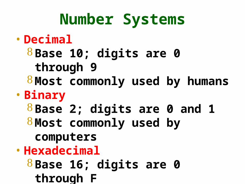
Number Systems• Decimal
Base 10; digits are 0 through 9 Most commonly used by humans
• Binary Base 2; digits are 0 and 1 Most commonly used by computers
• Hexadecimal Base 16; digits are 0 through F
• BCD Binary Coded Decimal

Decimal Binary Hex
0 0 0
1 1 1
2 10 2
3 11 3
4 100 4
5 101 5
6 110 6
7 111 7
8 1000 8
9 1001 9
10 1010 A
11 1011 B
12 1100 C
13 1101 D
14 1110 E
15 1111 F
Decimal (base 10)13410 = 4 x1 + 3x10 + 1x100 = 13410
Different Base Numbers
Binary (base 2)100001102 = 0x1 + 1x2 + 1x4
+0x8 + 0x16 + 0x32+0x64 + 1 x 128 = 13410
Hex (base 16)8616 = 6x1 + 8x16 = 13410

Logic Gates
• AND gate• OR gate• XOR gate
• NAND gate• NOR gate• XNOR gate
Inverter
(NOT gate)

Logic Inverter
• A logic inverter switches the state of its input. Changes 0 to 1
Changes 1 to 0
• Logic inverters can invert the outputs of other logic gates. Change an AND gate to a NAND gate Change an OR gate to a NOR gate Change an XOR gate to an XNOR gate
A10
B01AB

AND/NAND Logic Functions
• AND function
• NAND function
B0011
C0101
A0001
B0011
C0101
A1110
ABC
ABC

OR/NOR Logic Functions
OR function
NOR function
B0011
C0101
A0111
B0011
C0101
A1000
ABC
ABC

XOR/XNOR Logic Functions
XOR function
XNOR function
B0011
C0101
A0110
B0011
C0101
A1001
ABC
ABC
A = B+C
A = B+C

DeMorgan’s Theorems
XAB
XAB
A + B = A • B
=
A • B = A + B
AB
XAB = X

Combinational Logic Circuits
A B C X
0 0 0 0
0 0 1 0
0 1 0 0
0 1 1 0
1 0 0 0
1 0 1 1
1 1 0 1
1 1 1 1
A
BC
X
X = A(B + C)

X = ABC + ABC + ABC + ABC
A B C X
0 0 0 0
0 0 1 1
0 1 0 0
0 1 1 0
1 0 0 0
1 0 1 1
1 1 0 1
1 1 1 1
Truth Table Boolean Expression Simplify
X = BC(A + A) + AB(C + C)
X = BC + AB
Factor:
1
{
1{

Flip-Flop Circuits
• Flip-flop circuits are digital devices that hold a 0 or 1 output until some event triggers them to the opposite output.
• They are commonly used for storing digital data on a temporary basis.

Major Types of Flip-Flop Circuits
• Set/reset (SR) flip-flops.
Q
Q
S
R
Q
Q
D
CLK
Q
Q
J
K
• J-K flip flops.
• D-type flip-flops.

Q
QS
R
SR Flip-Flop with Active HIGH Inputs
Q
Q
S
R
Time
Q
Q
S
R

Q
QR
S
SR Flip-Flop with Active LOW Inputs
Q
Q
S
R
Time
+VCC
+VCC
Q
Q
S
R

Q
R
CLK
S
Time
Clocked SR Flip-Flop
Q
Q
S
RCLK

Q
Q
D
Negative-Edge Triggered D Flip-Flop
Q
CLK
D
Time
CLK

Q
Q
J
Negative-Edge Triggered JK Flip-Flop
Q
CLK
J
Time
CLKK
K
Mode J K Q
Inhibit 0 0 Q
Set 1 0 1
Reset 0 1 0
Toggle 1 1 Q
Q
Q
JCLK
K
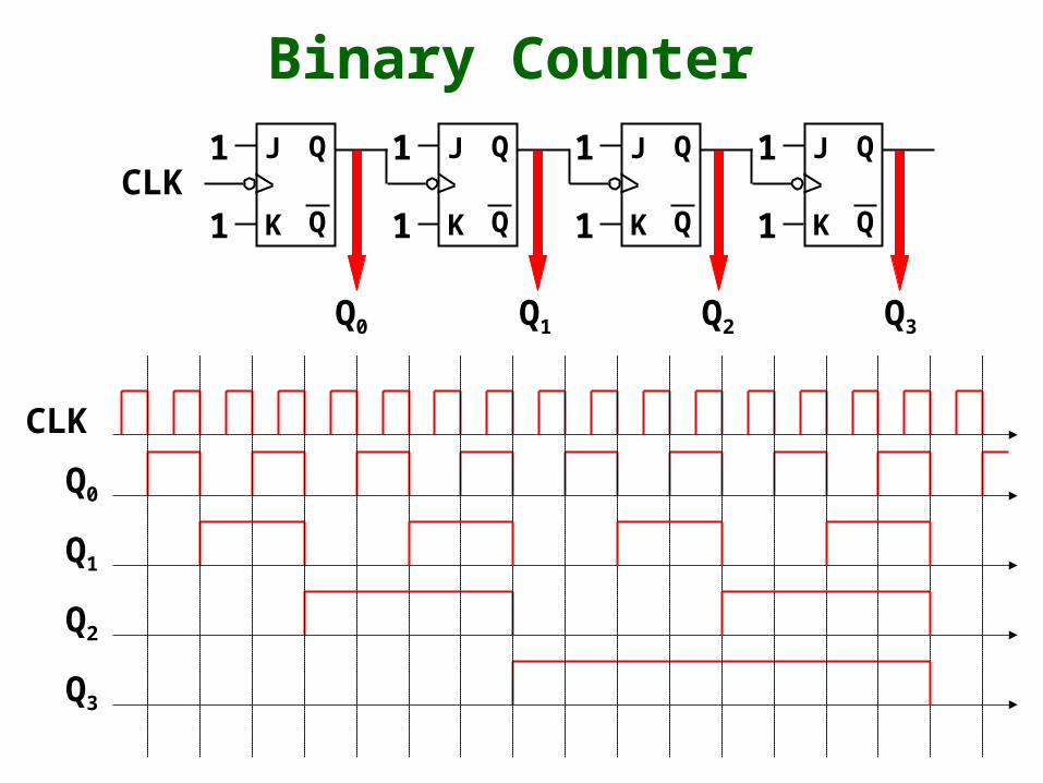
Binary Counter
1
1
Q
Q
J
K
1
1
Q
Q
J
K
1
1
Q
Q
J
K
1
1
Q0 Q1 Q2 Q3
Q2
CLK
Q0
Q1
Q3