basic electrical parameters measurement laboratory: a k-12
TRANSCRIPT

Paper ID #21411
Basic Electrical Parameters Measurement Laboratory: A K-12 OutreachProject
Dr. Rohit Dua, Missouri University of Science & Technology
ROHIT DUA, Ph.D is an Associate Teaching Professor in the Department of Electrical and Computer En-gineering at the Missouri University of Science and Technology and Missouri State University’s Coopera-tive Engineering Program. His research interests include engineering education. (http://web.mst.edu/˜rdua/)
c©American Society for Engineering Education, 2018
Basic Electrical Parameters Measurement Laboratory: A K-12 Outreach
Project
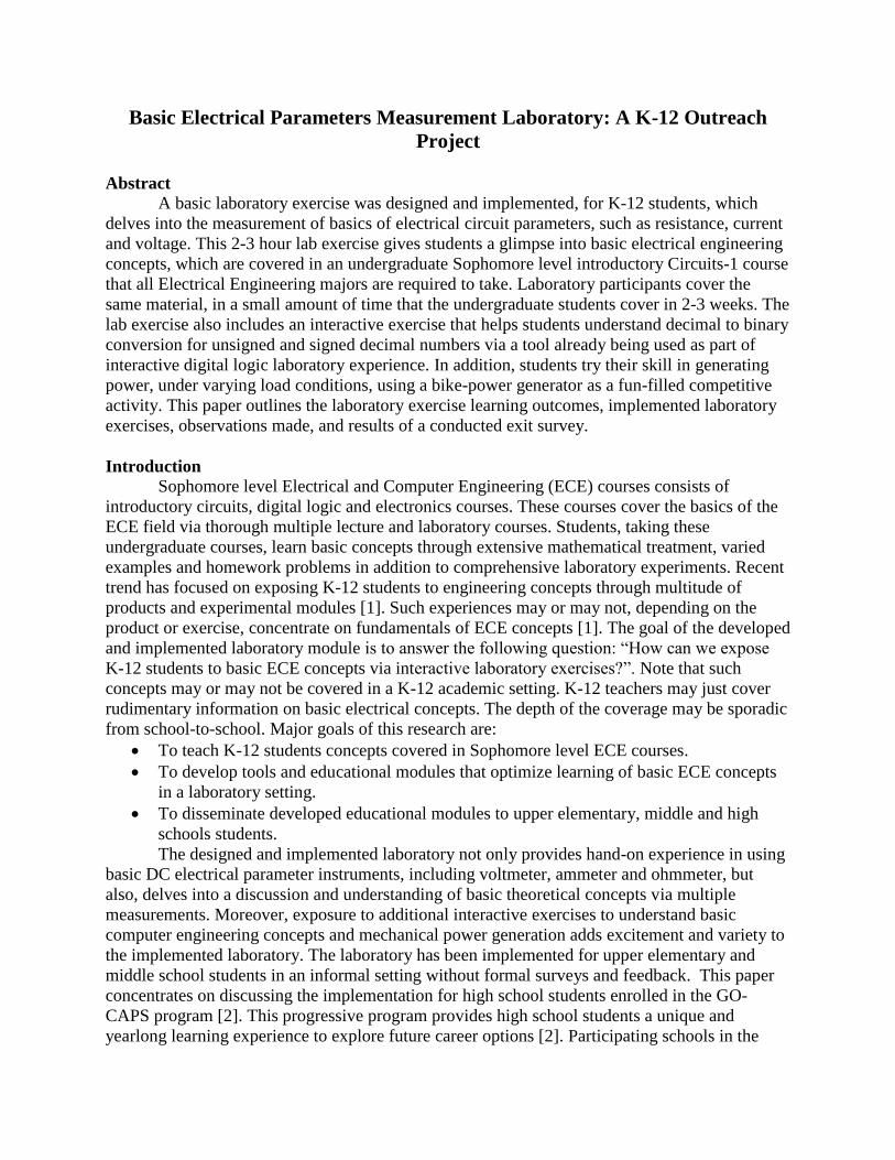
Abstract
A basic laboratory exercise was designed and implemented, for K-12 students, which
delves into the measurement of basics of electrical circuit parameters, such as resistance, current
and voltage. This 2-3 hour lab exercise gives students a glimpse into basic electrical engineering
concepts, which are covered in an undergraduate Sophomore level introductory Circuits-1 course
that all Electrical Engineering majors are required to take. Laboratory participants cover the
same material, in a small amount of time that the undergraduate students cover in 2-3 weeks. The
lab exercise also includes an interactive exercise that helps students understand decimal to binary
conversion for unsigned and signed decimal numbers via a tool already being used as part of
interactive digital logic laboratory experience. In addition, students try their skill in generating
power, under varying load conditions, using a bike-power generator as a fun-filled competitive
activity. This paper outlines the laboratory exercise learning outcomes, implemented laboratory
exercises, observations made, and results of a conducted exit survey.
Introduction
Sophomore level Electrical and Computer Engineering (ECE) courses consists of
introductory circuits, digital logic and electronics courses. These courses cover the basics of the
ECE field via thorough multiple lecture and laboratory courses. Students, taking these
undergraduate courses, learn basic concepts through extensive mathematical treatment, varied
examples and homework problems in addition to comprehensive laboratory experiments. Recent
trend has focused on exposing K-12 students to engineering concepts through multitude of
products and experimental modules [1]. Such experiences may or may not, depending on the
product or exercise, concentrate on fundamentals of ECE concepts [1]. The goal of the developed
and implemented laboratory module is to answer the following question: “How can we expose
K-12 students to basic ECE concepts via interactive laboratory exercises?”. Note that such
concepts may or may not be covered in a K-12 academic setting. K-12 teachers may just cover
rudimentary information on basic electrical concepts. The depth of the coverage may be sporadic
from school-to-school. Major goals of this research are:
To teach K-12 students concepts covered in Sophomore level ECE courses.
To develop tools and educational modules that optimize learning of basic ECE concepts
in a laboratory setting.
To disseminate developed educational modules to upper elementary, middle and high
schools students.
The designed and implemented laboratory not only provides hand-on experience in using
basic DC electrical parameter instruments, including voltmeter, ammeter and ohmmeter, but
also, delves into a discussion and understanding of basic theoretical concepts via multiple
measurements. Moreover, exposure to additional interactive exercises to understand basic
computer engineering concepts and mechanical power generation adds excitement and variety to
the implemented laboratory. The laboratory has been implemented for upper elementary and
middle school students in an informal setting without formal surveys and feedback. This paper
concentrates on discussing the implementation for high school students enrolled in the GO-
CAPS program [2]. This progressive program provides high school students a unique and
yearlong learning experience to explore future career options [2]. Participating schools in the

Greater Ozarks area, in Missouri (USA), are allotted a number of seats in the program. Students
from the participating schools apply for the GO-CAPS program in their choice of area. The GO-
CAPS board selects students based on the student’s interest and willingness to engage in the
program. The laboratory exercise was implemented for students enrolled in the ‘Engineering and
Manufacturing’ area of the GO-CAPS program. A part of their year long experience was to
explore the undergraduate ECE degree offered at the Missouri University of Science and
Technology and Missouri State University’s (MSU) Cooperative Engineering program, housed
at MSU, which is located in the Ozarks. The developed and implemented laboratory exercise
proved to be an ideal activity to expose high school students to ECE concepts. Note that the
developed laboratory is not only meant for students enrolled in GO-CAPS program, but also for
upper elementary, middle and other high school students.
The next section describes the implemented laboratory components and exercises.
Examples of implemented laboratory follows the next section followed by results of a conducted
exit survey. The paper concludes by discussing potential planned improvements for future
laboratory sessions.
Lab Description and Implementation
The learning objectives outlined for the proposed research is vast and continually
evolving. Covering all the considered engineering concepts will take multiple laboratory
sessions. In order to accommodate GO-CAPS students only a subset of the considered learning
objectives were implemented and include:
1. Understand how resistors are connected in series and parallel on a breadboard.
2. Develop skill in using an ohmmeter, voltmeter and ammeter to measure basic electrical
parameters.
3. Investigate the applications of Kirchoff’s voltage and current laws.
4. Assess the effect of connecting resistors in series and parallel on the overall resistance via
electrical measurements.
5. Develop skill in converting positive and negative decimal integers into equivalent binary
representation
6. Explore electrical power generation and usage via the bike power generator connected to
variable light bulb loads.
The electrical parameters measurement exercises were designed to emphasize the following
concepts in order:
Use an ohmmeter to measure resistance of individual resistors, resistors connected in
series and parallel
o Understand how resistance changes when resistors are connected in series as
compared to when resistors are connected in parallel.
Use a voltmeter to measure the source voltage, and the voltage across individual resistors
connected in a series circuit
o Verify Kirchhoff’s Voltage Law (KVL) in the series circuit
o In addition, measurements must emphasize the following rule: When resistors are
connected in a series circuit, the voltage across a particular resistor is directly
proportional to its resistance value.

Use an ammeter to measure the source current and the current flowing through individual
resistors connected in a parallel circuit.
o Verify Kirchhoff’s Current Law (KCL) in the parallel circuit
o In addition, measurements must emphasize the following rule: When resistors are
connected in a parallel circuit, the current through a particular resistor is inversely
proportional to its resistance value.
The practical study of Electrical Engineering concepts is generally carried out by building
test circuits on a solderless breadboards and running measurement-based experiments. Therefore,
the choice of using a breadboard as the platform for the planned experiments was obvious. Note,
experience has shown that it takes some time, spanning over multiple laboratory sessions, for
some undergraduate Electrical and Computer Engineering students to grasp the concept of
creating working circuits on breadboards. Owing to limited available laboratory session time, the
exercise of learning how to build circuits on breadboard was omitted. Though, a basic discussion
of how resistors are connected, on a breadboard, was carried out at the beginning of the
laboratory exercise. Figure 1 shows the circuit, on breadboard, which was used for the laboratory
exercise.
Figure 1: Circuit used for the laboratory exercise. The different circuits cover the different
planned exercises. The resistors were color-coded for ease of visualization.
Two resistor values were chosen to keep the circuits and measurements simple. The
resistors were color-coded. All resistors have a 1% tolerance value so that the measurements
would be close to the expected values. R1, which is a 1 kΩ (blue color) resistor and R2, which is
a 500 Ω (brown color) resistor were used as seen in Figure 1. R1 and R2 are also connected in a
series circuit, which is also used for voltage measurement. R1 and R2 are also connected in
parallel circuit, which is also used for current measurement. After a brief discussion on the
circuits and resistors, students attempted the first experiment, which is measuring resistance
value. Each student was given the experimental procedures manual, which also served as a lab
notebook to write the taken measurements, calculations and comments. In addition, each group
Same points
R1 (Blue)
R2 (Brown)
Voltage MeasurementCircuit
CurrentMeasurementCircuit

was given a Digital Multi-Meter (DMM) and a variable DC power supply for the implemented
exercises.
Students were shown the terminals used for measuring resistance, which are also used for
measuring voltage. The measuring leads were color coated for ease of usage. A red lead was
used for the positive terminal (+) and a black lead was used for the negative (-) terminal. First,
students were asked to identify the stand-alone R1 (blue resistor) on the breadboard. Setting the
DMM, on ohmmeter, students were instructed to connect the measurement leads across the
resistor under test and observe the resistance value on the meter display. Visual aids, shown in
Figure 2, helped students understand and make the connections for required measurements.
Figure 2: Circuit diagrams to aid the measurement of resistance using an ohmmeter. R1 and R2
are individual resistors. The circuit on the bottom left is the series resistance circuit, which is also
used for voltage measurements. The circuit on the bottom right is the parallel resistance circuit,
which is also used for current measurements.
Students were also asked to observe the effect on the resistance values, of individual
resistors, if the leads labeled ‘plus’ (red) and ‘minus’ (black) were interchanged. Similarly, the
resistance of R2, series resistance circuit and parallel resistance circuit were measured. As
students made measurements for series and parallel resistance circuit, they were asked to draw
conclusions on how the resistance changes when resistors are connected in series and in parallel.
Students were asked to relate the measured resistance values to the individual resistor values.
Suitable equations were given to provide mathematical reasoning to the observed measured
values.
The next laboratory exercise concentrated on measuring voltages. For this exercise the
series resistance circuit, as shown in Figure 1, was used. Students were asked to turn on the DC
power supply and set the source voltage to 2V. As with the DMM, the power supply leads were

also color coded for ease of usage. The red measurement lead was connected to the positive
terminal of the power supply and the black measurement lead was connected to the negative
terminal of the power supply. First, students were asked to measure the source voltage using the
voltmeter. To take advantage of the set color coding, students were asked to connect the red lead
(plus) of the voltmeter to the red lead of the power supply and the black lead (minus) of the
voltmeter to the black lead of the power supply. Students were asked to adjust the voltage to get
as close as to 2V as possible. In addition, students were asked to observe, what would happen if
the leads labeled ‘plus’ and ‘minus’ were interchanged, when making measurement. Voltage
values can be positive or negative polarity depending on how a particular measurement is made.
This concept is important to understand and students were asked to comprehend this concept via
multiple measurements across the same circuit element. Then, students were asked to identify the
series circuit and connect the 2V DC source across the series circuit. A circuit diagram, as shown
in Figure 3, was provided to aid the understanding of the planned measurements.
Figure 3: Circuit aid used explain voltage measurements for the series resistor circuits.
Students were asked to measure the voltage across each resistor taking care of the
polarity of the connections. As students took measurements, they were asked to apply Ohm’s law
to calculate the current flowing through that resistor. In addition, through measurements,
students were asked to verify:
The sum of measured voltages across the resistors (V1 + V2) must equal the supply
voltage (Vs) value of 2V (Figure 3). This is the basic understanding of the important
Kirchhof’s Voltage Law (KVL).
The voltage across a resistor is directly proportional to its resistance value.
The current flowing through the series connected resistors must be same.
The next laboratory exercise delved into the measurement of current in a parallel
connected resistor circuit. Students were asked to set the DMM to the ammeter setting. Again,
color coding was used to identify the positive (red) and the negative (black) terminals of the
ammeter. Measuring current is a bit a tricky since the ammeter needs to be placed in the path of
the current. This task requires breaking the circuit and placing the ammeter in the path of the
current. This portion of the lab took the longest time. In addition, effort was made to show the
current measuring process multiple times so that the technique would sink in. Visual aids, as

shown in Figure 4, were provided, which helped students understand the process of connecting
an ammeter.
Figure 4: Circuit aid used to explain the procedure used to connect an ammeter to measure
current ‘I’. Using this information students were challenged to figure out the process to measure
‘I1’ and ‘I2’
Students were asked to observe what would happen if the leads labeled ‘plus’ and
‘minus’, of the ammeter, are interchanged. Current can be positive or negative depending on how
measurements are made, which in mentions the direction of current flow. Students were asked to
measure the source current, as shown in Figure 4, and the current through each resistor taking
care of the correct method to connect the ammeter. As students took measurements, they were
asked to apply Ohm’s law to calculate the voltage across each resistor. In addition, through
measurements, students were asked to verify:
The sum of the measured currents through the resistors (I1 + I2) must equal to the
measured source current (I) (Figure 4). This is the basic understanding of the important
Kirchhof’s Current Law (KCL)
The current through a resistor is inversely proportional to its resistance value.
The voltage across parallel connected resistors must be same.
Figure 5 shows examples of students working on the measurement exercises. As students
finished the assigned measurements exercises, they were asked to complete the Computer
Engineering learning module [3, 4], in which they answered the following questions:
How unsigned (positive) decimal integers are represented, in binary, in computers?
How signed (positive and negative) decimal integers are represented, in binary, in
computers?

Figure 5: Students working on the electrical parameters measurement laboratory exercises.
Figure 6: Students using the B-To-D Emulator to practice converting decimal integers into
binary equivalent representation.

The B-To-D emulator has been successfully demonstrated at numerous events and helped
many K-12 students understand the decimal to binary conversion process via an interactive tool
[3, 4]. Figure 6 shows examples of students using the emulator to learn Decimal to Binary
conversion. In addition, students tried their skill in generating electrical power, using the in-
house built manual bike-power generator. This fun and physically challenging exercise gives
students an opportunity to understand the power generation requirements for different kinds of
load lamps, ranging from incandescent bulbs, which require more power to operate, to CFC and
LED bulbs, which require less power to operate. Figure 7 shows examples of students trying
their skill on generating power.
Figure 7: Students trying their skill in generating power.
Survey Results:
21 students participated in the laboratory exercise. Even though, the lab has been
implemented for more students, in the past, only 21 students conducted the survey. Students
were asked to respond to several statements (Strongly Agree to Strongly Disagree) related to the
covered laboratory components. Figures 8-10 show the results of the conducted survey. The
figures also show a brief discussion and interpretation of the results. The survey results show an
overall positive and enjoyable learning experience for the participants. Answers to open-ended
questions yielded a desire to learn more about the covered concepts. Though many participants
have chosen an alternate engineering career path, students were eager to learn basic Electrical
and Computer Engineering concepts.
Conclusion and Future Work
Even though the laboratory was a successful endeavor, there is room for improvement.
Given an opportunity to increase the duration of the laboratory and to reduce the number of
students, in a session, deeper learning can be achieved. This aspect will be explored in future
laboratory sessions. Furthermore, the laboratory exercise will be expanded to include additional
components that explore the mentioned electrical engineering concepts in more detail. Currently,
the laboratory sessions are held on university campus. K-12 students are required to attend the
sessions on university campus. An important future endeavor is to make the entire laboratory
portable. This resource will allow sessions to be held at K-12 schools. Past experience has shown
that some of the sessions could not be scheduled owing to time conflicts and transportation
issues. Moreover, the entire laboratory took about two hours to finish, which worked well within
the available schedule of participants. The laboratory exercises concentrate on analysis of
circuits. A design component was not included. Future work will concentrate on incorporating

design component/s, which will most likely increase the duration of the laboratory and will
probably work best for groups that can fit the entire laboratory exercise into their schedule.
Comment
Strongly Agree
Discussion
Agree
Neutral
Disagree
Strongly Disagree
I found the lab to be
an interesting
experience
Most students found the lab to be
an interesting learning experience.
I can easily use the
ohmmeter to
measure resistance
Most students found it easy to use
an ohmmeter to measure
resistance.
I can easily use the
voltmeter to
measure voltage
Most students found it easy to use
a voltmeter to measure voltage.
The operation is similar to using
an ohmmeter.
I can easily use the
ammeter to measure
the current
Only a few students found it easy
to use an ammeter to measure
current, which is tricky since the
ammeter needs to be placed in the
path of the current flow.
I understand how
the overall
resistance changes
when the resistors
are connected in
series
Most students were able to
understand via measurements that
the overall resistance increases,
when resistors are connected in
series.
Figure 8: Results of the Survey and Discussion
I found the lab to be an interesting learning experience
Strongly Agree Agree Neutral Disagree Strongly Disagree
I can easily use the ohmmeter to measure resistance
Strongly Agree Agree Neutral Disagree Strongly Disagree
I can easily use the voltmeter to measure voltage
Strongly Agree Agree Neutral Disagree Strongly Disagree
I can easily use the ammeter to measure current
Strongly Agree Agree Neutral Disagree Strongly Disagree
I understand how the overall resistance changes when resistors are connected in series
Strongly Agree Agree Neutral Disagree Strongly Disagree
Comment
Strongly Agree
Discussion
Agree
Neutral
Disagree
Strongly Disagree
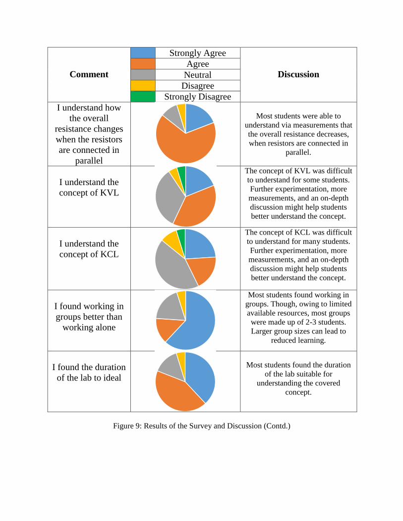
I understand how
the overall
resistance changes
when the resistors
are connected in
parallel
Most students were able to
understand via measurements that
the overall resistance decreases,
when resistors are connected in
parallel.
I understand the
concept of KVL
The concept of KVL was difficult
to understand for some students.
Further experimentation, more
measurements, and an on-depth
discussion might help students
better understand the concept.
I understand the
concept of KCL
The concept of KCL was difficult
to understand for many students.
Further experimentation, more
measurements, and an on-depth
discussion might help students
better understand the concept.
I found working in
groups better than
working alone
Most students found working in
groups. Though, owing to limited
available resources, most groups
were made up of 2-3 students.
Larger group sizes can lead to
reduced learning.
I found the duration
of the lab to ideal
Most students found the duration
of the lab suitable for
understanding the covered
concept.
Figure 9: Results of the Survey and Discussion (Contd.)
I understand how the overall resistance changes when resistors are connected in parallel
Strongly Agree Agree Neutral Disagree Strongly Disagree
I understand the concept of KVL
Strongly Agree Agree Neutral Disagree Strongly Disagree
I understand the concept of KCL
Strongly Agree Agree Neutral Disagree Strongly Disagree
I found working in groups better than working alone
Strongly Agree Agree Neutral Disagree Strongly Disagree
I found the duration of the lab to be ideal
Strongly Agree Agree Neutral Disagree Strongly Disagree

Comment
Strongly Agree
Discussion
Agree
Neutral
Disagree
Strongly Disagree
I found the
difficulty level of
the lab to be
reasonable
Many students were able to
comprehend most of the covered
concepts. But, some students had
difficulty understanding some of
the concepts as mentioned above.
At the end of the
lab, I am more
curious about
Electrical
Engineering
Not every participant was
interested in pursuing a career in
Electrical Engineering. Based on
an asked open-ended question,
many student had already chosen
a different career path other than
Electrical Engineering.
I found the B-To-D
converter a useful
tool to understand
decimal to binary
conversions
The very successful tool has yet
again proved effective in teaching
students the technique to convert
decimal numbers to binary
I understand how
decimal numbers
are converted into
binary
Most students were able to easily
understand the process of
converting decimal to binary
using the tool. Though, some
more practice, with the tool, may
been needed to nail the technique
I understand how
negative numbers
are represented in
binary using 2s
complement method
While understanding the
conversion of positive numbers,
into binary, is relatively easy, the
concept of converting negative
numbers into binary was a bit
tricky for some to understand.
Figure 10: Results of the Survey and Discussion (Contd.)
Future work will, also, concentrate on expanding the implemented laboratory exercises,
implementing the sessions for middle and upper-elementary grade students in a more formal
setting, which will include feedback in the form of conducted survey.
I found the difficulty level of the lab to be reasonable
Strongly Agree Agree Neutral Disagree Strongly Disagree
At the end of the lab, I am more curious about Electrical Engineering
Strongly Agree Agree Neutral Disagree Strongly Disagree
I found the B-To-D Converter a useful tool to understand decimal to binary conversions
Strongly Agree Agree Neutral Disagree Strongly Disagree
I understand how decimal numbers are converted to binary
Strongly Agree Agree Neutral Disagree Strongly Disagree
I understand how negative numbers are represented in binary using 2s complement
method.
Strongly Agree Agree Neutral Disagree Strongly Disagree

References
1. ELENCO: Learn By Doing Webpage, “SNAP Circuits: Experiments Toys,” (Accessed
January 27, 2017). Available: https://www.elenco.com/brand/snap-circuits/
2. GO-CAPS webpage, “Greater Ozarks Centers for Advanced Professional Studies,” (Accessed
March 15, 2018). Available: https://gocaps.yourcapsnetwork.org/
3. R. Dua, “Interactive Digital Logic Laboratory for K-12 Students (Work in Progress),” 2017
ASEE Annual Conference & Exposition, Columbus, OH, USA
4. N. Kelly, K. Brown, R. Dua, “Work-In-Progress Interactive Digital Logic Laboratory for
Kids: Decimal-To-Binary Conversion Emulator – An Experiential Learning Project,” 2015
ASEE Zone III Conference student paper competition winner. Springfield, MO, USA