basic design study report on the project for …open_jicareport.jica.go.jp/pdf/11925914_01.pdf ·...
TRANSCRIPT

BASIC DESIGN STUDY REPORT
ON
THE PROJECT
FOR
IMPROVEMENT OF THE METEOROLOGICAL RADAR SYSTEM
IN
THE PHILIPPINES
January 2009
JAPAN INTERNATIONAL COOPERATION AGENCY
JAPAN WEATHER ASSOCIATION
GE
JR
09-002
NO. Philippine Atmospheric, Geophysical and Astronomical Services Administration
BASIC DESIGN STUDY REPORT
ON
THE PROJECT
FOR
IMPROVEMENT OF THE METEOROLOGICAL RADAR SYSTEM
IN
THE PHILIPPINES
January 2009
JAPAN INTERNATIONAL COOPERATION AGENCY
JAPAN WEATHER ASSOCIATION

PREFACE In response to a request from the Government of the Republic of the Philippines, the
Government of Japan decided to conduct a basic design study on the Project for Improvement of the Meteorological Radar System in the Philippines and entrusted the study to the Japan International Cooperation Agency (JICA).
JICA sent to the Philippines a study team from June 26 to August 3, 2008. The team held discussions with the officials concerned of the Government of the
Philippines, and conducted a field study at the study area. After the team returned to Japan, further studies were made. Then, a mission was sent to the Philippines in order to discuss a draft basic design, and as this result, the present report was finalized.
I hope that this report will contribute to the promotion of the project and to the
enhancement of friendly relations between our two countries. I wish to express my sincere appreciation to the officials concerned of the Government
of the Republic of the Philippines for their close cooperation extended to the teams.
January, 2009
Ariyuki MATSUMOTO Vice-President Japan International Cooperation Agency

January, 2009
Letter of Transmittal
We are pleased to submit to you the basic design study report on the Project for Improvement of the Meteorological Radar System in the Philippines.
This study was conducted by Japan Weather Association, under a contract to JICA,
during the period from June, 2008 to January, 2009. In conducting the study, we have examined the feasibility and rationale of the project with due consideration to the present situation of the Philippines and formulated the most appropriate basic design for the project under Japan's Grant Aid scheme.
Finally, we hope that this report will contribute to further promotion of the project.
Very truly yours,
Yoshihisa UCHIDA Project Manager Basic design study team on the Project for Improvement of the Meteorological Radar System in the Philippines Japan Weather Association

Summary

S - 1
Summary
The Philippine archipelago, located near the western edge of the Pacific Ocean, is in the direct path of
seasonal typhoons and monsoon rains which bring floods, storm surges, and their attendant landslides and
other forms of devastation. For the past 60 years, an average of 19 to 20 tropical cyclones per year
occurred in the Philippine Area of Responsibility (PAR). An annual average of 8 to 9 tropical cyclones
made landfall/crossed the country. The Philippines has long been associated with extreme vulnerability to
natural disasters, and has particularly been affected by tropical cyclones. The National Disaster
Coordinating Council (NDCC) record says that approximately the number of dead, injured and missing
people is in the vicinity of 12 thousand, the number of disaster victims is approximately 49 million, and
the total cost of damage is estimated to be around 77 billion Pesos for the last 10 years between 1998 and
2007. The devastation from tropical cyclones and sever weather disturbances has accounted for 92.5% of
the total damage from natural disasters. Every year, the Philippines seriously experience huge economic
losses coupled with human anguish and sufferings generated by destructive tropical cyclones that cross the
country. They have caused significant damage to agriculture which is a vital industry in the Philippines,
thereby inflicting widespread poverty on its people. The extensive damage from tropical cyclones is a
determining factor for the significant set-back of the national economy. They adversely affect the people’s
standard of living. To alleviate and proactively deal with the situations indicated above, establishment of
effective countermeasures against natural disasters resulting from tropical cyclones is of pressing urgency.
The 4-Point Action Plan of the National Government was conceptualized after the series of tragedies in
2004 that hit Aurora and Quezon Provinces, and some neighboring areas. President Gloria Macapagal-
Arroyo gave the go-signal for the immediate adoption and execution of a National Action Plan in disaster
preparedness. The components of the 4-point action plan are to upgrade 1) PAGASA forecasting
capability, 2) public information campaign on disaster preparedness, 3) capability building for local
government units in identified vulnerable areas, and 4) mechanisms for government private sector
partnership in relief and rehabilitation.
The Medium-Term Philippine Development Plan for 2004 to 2010 (MTPDP) embodies the 10-point
agenda of the Arroyo administration. Its number five thrust is to mitigate the occurrence of natural
disasters to prevent the loss of lives and properties. It is also focused on fighting against poverty of the
greatest number of the Filipino people and employ strategic measures that will sustain economic growth.
In addition, the National Science and Technology Plan for 2002-2020 (NSTP 2020) is a long-term plan
that defines the direction of science and technology (S&T) development in the Philippines until year 2020.
Among the priority sectors identified for S&T development includes natural disaster mitigation, which
point toward the urgent implementation of the Project to minimize damage caused by natural disasters.
The Philippine Atmospheric, Geophysical and Astronomical Services Administration (PAGASA) is the
sole national meteorological service provider in the Philippines and is under the administrative supervision

S - 2
of the Department of Science and Technology. Its main responsibility as a National Meteorological
Service is to record meteorological observations round the clock and to provide weather information,
forecasts, advisories and warnings necessary for the mitigation and prevention of natural disasters and
improvement of socio-economic conditions.
In view of the current situation of the meteorological observation capability of PAGASA through its
existing meteorological radar systems and facilities, the Philippines is beset by the following issues and
major concerns:
[1] Due to the age of the existing Virac, Aparri and Guiuan radar systems, it is difficult to conduct
radar monitoring for a number of reasons such as the transmitted power is down, each circuit in
the system is obsolete, and radar pictures in the display are unreadable. Therefore, currently
PAGASA is not able to appropriately monitor the tropical cyclones in the Pacific Ocean, and
cannot accurately detect the centers or intensities. Consequently, the Meteorological Radar
Stations cannot provide the required information to the Weather and Flood Forecasting Center
(WFFC) as an input for the preparation of the public storm signal warning and tropical cyclone
information.
[2] Since the existing radar systems have no Doppler function, PAGASA is unable to monitor in real
time basis stormy wind generated by tropical cyclone, including direction of rainfall motion, and
detection of local severe storm associated with tornados in the Pacific Ocean and the coastal
areas and cannot accurately locate cyclone centers or intensities of the numerous tropical
cyclones and detect heavy rainfall area since no wind convergence area data is contained in the
radar observed data.
[3] The existing radar tower buildings at Virac, Aparri and Guiuan Meteorological Radar
Observation Stations have seriously structurally deteriorated, and continued use of those
buildings is now quite dangerous.
[4] There is no data communication system to transmit the meteorological radar data such as rainfall
intensity, wind speed/direction, etc. from the proposed Meteorological Radar Systems to the
Weather & Flood Forecasting Center (WFFC) of PAGASA.
In order to effectively protect life and property from tropical cyclone damage, it is urgent to remedy the
current situation as soon as possible. It is therefore imperative to establish a reliable and timely
dissemination of public storm signal warning and tropical cyclone information to the public and disaster
management agencies. Because of lack of financial and technical capabilities, the Government of the
Philippines has requested the Government of Japan to procure and install the required equipment,

S - 3
construct appropriate radar tower buildings, as well as provision of relevant systems and facilities, etc.
under Japan’s Grant Aid Assistance scheme.
In response to the request from the Government of the Philippines, the Government of Japan decided to
conduct a Preparatory Study for the Project under the Japan International Cooperation Agency (JICA) that
commission a Preparatory Study Team to the Philippines from November 11 to December 12, 2007 in
order to confirm feasibility and appropriateness of Project implementation.
In accordance with the result of the Preparatory Study, the Government of Japan decided to conduct a
Basic Design Study for the Project, and consequently the Japan International Cooperation Agency (JICA)
sent the Basic Design Study Team to the Philippines from June 26 to August 3, 2008. The team had a
series of discussions with the Philippine Government officials, conducted surveys and collected necessary
information and data for the Project.
Upon return to Japan, the team conducted further studies including feasibility, justification and scope of
the Project, paying particular attention to the present situation in the Philippines, especially on the
operation and maintenance capabilities of PAGASA. From those studies, the team formulated the draft
basic design for the Project. JICA then sent the team again to the Philippines from October 20 to
November 5, 2008 in order to discuss the draft basic design study report. Accordingly, the basic design
for the Project was finalized.
The concluded items in the basic design for the Project are as follows.
The required implementation period of the Project, including the detailed design study and the tendering
procedures, is approximately 50 months. The project cost to be borne by the Philippines, as estimated in
the basic design study, is approx. 213,690,000 Peso (approx.555 Million JP Yen).
After completion of the Project, the following benefits and improvements can be expected.
[1] Enable PAGASA to conduct more extensive monitoring of sever phenomena and tropical
Table 1: Concluded Items for the Project
Items Head Office
(WFFC)
Virac Meteorological
Radar Observation
Station
Aparri Meteorological
Radar Observation
Station
Guiuan Meteorological
Radar Observation
Station
Procurement and Installation of Equipment
S-Band Doppler Radar System including Power Back-up System, Lightning System, Measuring Equipment and Spare Parts
- 1 1 1
Data Display Systems including Software 1 1 1 1
Meteorological Data Satellite Communication System (VSAT) 1 (Hub) 1 1 1
Construction of Radar Tower Building
Radar Tower Building with Furniture - 1 1 1

S - 4
cyclone since the meteorological radar detection range of precipitation intensity 1mm/h or more
will be increased from 300km radius to 450km radius.
[2] Enable PAGASA to monitor tropical cyclonic wind velocity maximum 75m/s and detect the
direction of rainfall motion within 200km radius from the time when the meteorological Doppler
radar systems will be installed in Virac, Aparri and Guiuan.
[3] Enable PAGASA to issue an hourly public storm signal warning and tropical cyclone
information (intensity, location and track) to agencies concerned with disaster management, the
mass media, etc. during tropical cyclone in the radar detection range given that 24 hours
continuous operation can be made and the rainfall intensity and wind speed/direction, etc. of
tropical cyclone observed by Virac, Aparri and Guiuan Doppler radar systems can be received at
the WFFC in real time.
[4] Enable PAGASA to monitor stormy wind generated by tropical cyclone, detect local severe
storm associated with tornados that briefly occur in the Pacific Ocean and the coastal areas and
detect heavy rainfall area with wind convergence area data contained in the radar observed data
for prompt issuance of weather, flood and landslide warnings as the meteorological Doppler
radar systems will be installed in Virac, Aparri and Guiuan.
[5] Enable PAGASA to improve accuracy of flood forecasts and warnings because precipitation data
of 2.5 km mesh in the detection range of Virac, Aparri and Guiuan meteorological radar
observation network can be manually inputted to the existing flood forecasting model of the
WFFC.
PAGASA, the agency which will implement the Project, has quite a good organizational capability. Its
engineers have sufficient experience and knowledge in the daily operation, repair and maintenance of its
existing meteorological radar systems. Moreover, PAGASA’s budget is expected to be able to cover the
Philippine portion of the capital cost and recurrent cost of the Project indicated in this report.
As adequately pointed out in the above careful and comprehensive evaluation of the Project
effects, considerable and enhanced benefits can be expected to be achieved vis-à-vis PAGASA’s
capabilities in reducing human loss and the recurrent economic set-back brought about by
tropical cyclone disasters. The Project would substantially contribute to the mitigation of the
adverse effects of natural disasters and effectively safeguard the basic human needs of the
Filipino people. The foregoing indicates and amply confirms the appropriateness and necessity
of carrying out the Project under grant-aid scheme. The implementation of the Project is
therefore wholly considered to be appropriately suitable and worthwhile.

Contents Preface Letter of Transmittal Summary Contents Map of the Philippines and Surroundings Perspective Damage Records caused by Major Tropical Cyclones (1998 - 2007) List of Figures List of Tables Abbreviations Chapter 1 Background of the Project ............................................................................... 1 - 1 Chapter 2 Contents of the Project ...................................................................................... 2 - 1 2-1 Basic Concept of the Project ................................................................................... 2 - 1 2-2 Basic Design of the Requested Japanese Assistance ............................................... 2 - 2 2-2-1 Design Policy ....................................................................................................... 2 - 2 2-2-2 Basic Plan ........................................................................................................... 2 - 7 2-2-3 Basic Design Drawing ......................................................................................... 2 - 79 2-2-4 Implementation Plan ............................................................................................ 2 -115 2-2-4-1 Implementation Policy ..................................................................................... 2 -115 2-2-4-2 Implementation Conditions ............................................................................. 2 -115 2-2-4-3 Scope of Works ............................................................................................... 2 -116 2-2-4-4 Consultant Supervision .................................................................................... 2 -118 2-2-4-5 Quality Control Plan ........................................................................................ 2 -119 2-2-4-6 Procurement Plan ............................................................................................. 2 -120 2-2-4-7 Operational Guidance Plan .............................................................................. 2 -124 2-2-4-8 Implementation Schedule ................................................................................ 2 -126 2-3 Obligations of Recipient Country ........................................................................... 2 -127 2-4 Project Operation Plan ............................................................................................ 2 -133 2-5 Project Cost Estimate .............................................................................................. 2 -136 2-5-1 Estimate of Project Cost and Capital Cost to be borne by PAGASA .................. 2 -136 2-5-2 Estimate of Recurrent Cost for the Project to be borne by the Philippine side .... 2 -140 2-6 Other Relevant Issues .............................................................................................. 2 -144 Chapter 3 Project Evaluation and Recommendations ................................................... 3 - 1 3-1 Project Effect ........................................................................................................... 3 - 1 3-2 Recommendations ................................................................................................... 3 - 3

Appendices Appendix 1. Member List of the Survey Team ............................................................ APX1 - 1 Appendix 2. Study Schedule ........................................................................................ APX2 - 1 Appendix 3. List of Party Concerned in the Recipient Country ................................... APX3 - 1 Appendix 4. Minutes of Discussions ............................................................................ APX4 - 1 Appendix 5. References ................................................................................................ APX5 - 1

■ Philippines
PAGASA Head Office
Weather and Flood Forecasting Center (WFFC)
Aparri Existing Meteorological Radar Observation Station
Virac Existing Meteorological Radar Observation Station
Guiuan Existing Meteorological Radar Observation Station
N

Virac Meteorological Radar Tower Building

Aparri Meteorological Radar Tower Building

Guiuan Meteorological Radar Tower Building
Damage Records caused by Major Tropical Cyclones (1998 - 2007)
Date TC
Classification
Highest Maximum
Winds/Gusts(m/s)
Maximum 24 hr RR(mm)
Damage to Infrastructure
and Agriculture
(M Php)
Damage
Killed Missing Injured House
DestroyedHouse
Damaged
July 8 - 11, 1998 TD 8.0 84.0 August 1 - 5, 1998 TS 25.0 93.2 August 7 - 9, 1998 TD 15.0 235.6
August 24 - 25, 1998 TS (15.2) 81.1 September 16 - 17, 1998 T (22.2) 173.6 September 17 - 21, 1998 T 30.0 173.6 547,478.5 107 10 22 September 26 - 28, 1998 TS (17.5) 203.0
October 11 - 16, 1998 T 35.0 221.6 October 15 - 25, 1998 T 25.0 307.0
November 23 - 24, 1998 T 5.0 86.4 December 9 - 12, 1998 T 26.1 256.6
January 6 - 7, 1999 TD 5.0 30.2 February15 - 18, 1999 TD 8.0 10.4
April 8 - 9, 1999 TD 8.3 290.8 April 22 - 26, 1999 TS 5.5 236.1
June 1 - 6, 1999 T 23.0 242.2 June 4 - 6, 1999 TD (20.8) 108.7
July 21 - 26, 1999 TS 9.7 160.6 July 28 - August 1, 1999 T (18.0) 142.6
August 18 - 21, 1999 TS 23.0 433.4 146.25 7 2 23 August 31 - September 3, 1999 TS 11.9 200.8
September 10 - 15, 1999 TS 16.1 204.8 0.616 19 3 September 19 - 22, 1999 T 15.2 83.4
October 2 - 6, 1999 T 30.0 423.0 139.69 15 1 10 October 15 - 18, 1999 TS 18.0 323.4 November 7 - 9, 1999 TS 26.9 189.5
November 14 - 15, 1999 TS 8.3 37.9 May 6 - 9, 2000 T 8.3 118.0
May 18 - 19, 2000 TS 5.5 221.7 50.08 May 21 - 22, 2000 TD 9.7 64.0
July 2 - 6, 2000 TD 23.6 322.0 July 3 - 9, 2000 T 15.2 322.0 1,101.0
July 12 - 14, 2000 TD 5.0 121.8 July 21 - 25, 2000 TD 8.3 62.8
August 19 - 23, 2000 T 20.8 215.8 7.15 August 25 - 30, 2000 TS 9.7 101.5 September 2 - 7, 2000 TS 8.3 267.0 September 2 - 6, 2000 TS 25.0 235.0
September 10 - 12, 2000 T 23.6 182.1 October 23 - 25, 2000 T 20.8 46.7
October 25 - November 1, 2000 T 27.7 312.3 3,752.4 October 31 - November 5, 2000 T 25.0 238.5 699.2
November 27 - December 3, 2000 TS 18 168.4 488.7 December 6 - 8, 2000 TD 12.5 507.5 888.0
December 29, 2000 - January 1, 2001 TS 5.5 80.0 February 18 - 20, 2001 TD 16.1 151.4 20
April 18 - 19, 2001 TD 3.8 81.8 May 10 - 14, 2001 TS 31.9 242.2 June 17 - 20, 2001 TD 11.1 174.6 June 20 - 23, 2001 T 30.0 273.4
July 2 - 5, 2001 T 43.0 1085.8 1,500 163 180 60 July 9 - 12, 2001 TS 15.0 224.6 July 23 - 24, 2001 TS 30.0 224.6

July 26 - 30, 2001 T 33.0 127.8 August 16 - 19, 2001 TD (9.7) 145.5
September 17 - 19, 2001 TS (22.2) 54.5 September 22 - 28, 2001 T 50.0 355.2
October 11 - 16, 2001 T (20.8) 125.2 November 6 - 10, 2001 T 21.9 213.6 184 106 147 119 2,811 November 20 - 25, 2001 TS (20.8) 167.4 November 22 - 24, 2001 TD - 143.2
December 4 - 7, 2001 TS 21.1 161.5 January 10 - 14, 2002 TS 12.5 63.8
March 3 - 7, 2002 T (18.0) 49.2 March 20 - 23, 2002 TD (15.2) 61.1 March 28 - 30, 2002 TD 18.0 59.2
June 7 - 9, 2002 T 18.0 194.0 June 28 - July 3, 2002 T 30.5 96.0
July 7 - 9, 2002 T 18.0 346.8 July 9, 2002 TS 18.0 346.8
July 12 - 14, 2002 T 22.2 287.6 July 17 - 23, 2002 TD 15.2 231.4 July 22 - 25, 2002 T 18.0 250.9 August 1 - 3, 2002 TD 18.0 110.9
August 11 - 14, 2002 TD 18.0 254.2 April 16 - 24, 2003 T 31.1 80.4 May 19 - 20, 2003 TD 8.0 48.2 May 25 - 30, 2003 TS 23.8 722.6 538 44 8 19 178 2,040
May 31 - June 3, 2003 TS 28.0 237.0 June 13 - 18, 2003 T 25.0 315.6 131 12 2 2 176
July 9, 2003 TD 11.9 62.8 July 15 - 20, 2003 TS 18.8 95.0 67.25 4 4 1 July 19 - 23, 2003 ST 48.0 467.4 3,233 64 2 154 July 30 - 31, 2003 TD 11.9 76.8 7.98 August 1 - 4, 2003 TS 23.8 182.6 August 4 - 6, 2003 T 18.8 174.6 36.9
August 18 - 20, 2003 TS 20.0 128.1 August 19 - 20, 2003 TS 20.0 117.2 August 20 - 24, 2003 T 23.8 342.0 4,330 1
August 29 - September 2, 2003 T 46.1 296.7 1 1 September 7 - 10, 2003 T 16.1 79.0 September 15 - 19, 2003 TD 15.0 166.1 September 18 - 19, 2003 TS 18.0 148.8 September 25 - 26, 2003 TD 6.3 65.7 October 17 - 24, 2003 T 18.8 120.5 October 23 - 24, 2003 TD 21.9 107.4 0.094 1
October 30 - November 4, 2003 TS 33.8 173.4 November 12 - 15, 2003 TS 26.1 166.2 0.045 13 11 5 November 27 - 30, 2003 T 13.0 9.7 December 25 - 28, 2003 TD 16.9 - February 13 - 14, 2004 TD (15.2) 22.2 March 17 - 23, 2004 TS (25.0) 78.7 April 10 - 14, 2004 T (33.3) 14.0 May 13 - 20, 2004 T 25.0 244.0 35 6 23 May 19 - 21, 2004 TS - 104.2 June 5 - 9, 2004 T (22.2) 230.0 2 3 June 7 - 11, 2004 TS (13.8) 152.0 7 3 7 June 16 - 19, 2004 T (15.2) 138.4
June 25 - July 2, 2004 T 27.7 444.2 55 20 47 July 13 - 15, 2004 TS 13.8 55.2
August 6 - 11, 2004 T 25.0 84.3 August 15 - 17, 2004 TS 15.2 100.3 August 20 - 24, 2004 T 15.2 207.2

September 3 - 5, 2004 T 27.7 191.4 September 11 - 12, 2004 TS 15.2 152.4 September 15 - 17, 2004 TD (10.2) 135.9 September 24 - 26, 2004 T 22.2 34.8
October 4 - 8, 2004 T (15.2) 227.4 October 15 - 19, 2004 T (38.8) 82.3 October 22 - 25, 2004 T (25.0) 46.2
November 14 - 21, 2004 T 15.2 216.4 434.2 71 69 160 November 22 - 23, 2004 TD (15.2) 185.2 31 17 167 November 28 - 30, 2004 TD (15.2) 156.4 701.6 1,060 559 1,023 38,000 134,000
December 1 - 4, 2004 T 22.2 228.1 560.8 73 24 168 December 15 - 19, 2004 TS (15.2) 53.0
March 15 - 18, 2005 TS (15.2) 139.8 21.1 13 63 April 22 - 26, 2005 T (15.2) 26.5 May 16 - 17, 2005 TD - 36.8 June 3 - 8, 2005 T (15.2) 20.8 July 4 - 6, 2005 TD (15.2) 96.6
July 15 - 19, 2005 T 27.7 111.0 19 July 31 - August 5, 2005 T 37.5 145.6
August 10 - 13, 2005 TS (27.7) 302.5 August 29 - September 1, 2005 T 38.8 73.1
September 2 - 4, 2005 T 33.3 54.4 September 7 - 10, 2005 T 33.3 88.0 September 19 - 23, 2005 TS 26.9 402.0 496 9 5 5
September 29 - October 2, 2005 T 22.2 60.2 October 10 - 16, 2005 T (27.7) 79.8 November 8 - 11, 2005 TS (13.8) 154.4
November 14 - 20, 2005 T (36.1) 211.2 December 16 - 18, 2005 TD (33.3) 242.2 5 26 16 6 January 21 - 24, 2006 TD 10.2 184.0
March 6 - 7, 2006 TD 11.1 46.0 May 9 - 15, 2006 T 12.5 247.0 4,400 82 36 59 600 3,500 June 24 - 27, 2006 TS 10.2 118.0
July 2 - 9, 2006 T 18.0 157.0 July 10 - 14, 2006 T 20.8 355.4 1,200 45 6 33 July 21 - 25, 2006 T 15.2 303.4 77.8
July 28 - August 2, 2006 TS 16.6 206.6 223.7 12 6 1 August 5 - 9, 2006 TS 16.6 72.6 August 8 - 9, 2006 T 16.6 72.6
August 13 - 15, 2006 TS (25.0) 207.0 September 10 - 16, 2006 T 41.6 176.2 September 25 - 29, 2006 T 30.5 221.6 6,000 213 48 660 118,081
October 1 - 5, 2006 TS 19.4 159.0 October 12 - 13, 2006 TD (279.9) 70.1 October 27 - 31, 2006 T 16.6 227.0 1,200 32 23 62 1,395 November 8 - 12, 2006 T 11.1 176.2 1 10
November 28 - December 3, 2006 T 78.0 446.0 5,400 709 753 2,190 181,676 December 7 - 12, 2006 T 26.3 200.0 500 27 8 42 211,032 December 18 - 19, 2006 TS (18.0) 81.9
May 18 - 20, 2007 T (10.2) 112.0 July 11 - 13, 2007 T 26.3 179.6 August 5 - 8, 2007 TS 15.2 205.2 August 8 - 9, 2007 TS 9.72 302.7 307.1 15 1 10
August 13 - 18, 2007 T 15.2 228.0 69.7 5 1 1 September 13 - 14, 2007 T 10.2 106.0 September 15 - 18, 2007 T 38.8 80.2 2 September 27 - 30, 2007 TS 13.0 129.8
October 1 - 7, 2007 T 33.3 171.4 0.4 1 14 1 October 26, 2007 TS 13.0 52.0
November 3 - 7, 2007 T 10.2 119.0 120.3 6 2

November 19 - 22, 2007 November 26 - 28, 2007
T 20.8 228.9 9 5 11 7
November 21 - 28, 2007 T 20.8 134.8 735 31 21 8 * TC Classification
ST : Super Typhoon T : Typhoon TS : Tropical Storm TD : Tropical Depression * Highest Maximum Winds/Gusts
( ) : Over Water

List of Figures
Chapter 1 Background of the Project
Figure 1 Annual Frequency of Tropical Cyclone in the PAR (1948 - 2006) ............................ 1 - 1
Figure 2 Growth Rate of GDP and Damage generated by Typhoons ....................................... 1 - 8
Figure 3 Climate Map of the Philippines .................................................................................. 1 - 9
Figure 4 Virac, Aparri and Guiuan Monthly Mean Rainfall of 2001-2007 .............................. 1 - 10
Figure 5 Lightning-prone Area ................................................................................................. 1 - 10
Figure 6 Frequency of Tropical Cyclone passage over
each Geographical Zone in the Philippines ................................................................ 1 - 11
Chapter 2 Contents of the Project
Figure 7 Present Detection Range of the Existing Meteorological Radar Observation Network
in the Philippines ........................................................................................................ 2 - 11
Figure 8 Composite Picture of the Proposed Meteorological Radar Observation Network
in the Philippines ........................................................................................................ 2 - 12
Figure 9 Estimation of Minimum Required Space Segment ..................................................... 2 - 13
Figure 10 Schematic Diagram for the Project for Establishment
of the Meteorological Radar System in the Philippines ............................................. 2 - 16
Figure 11 Blind Area created by the Mountains and the Mobile Tower ..................................... 2 - 57
Figure 12 Aparri Meteorological Radar Observation Station and Surroundings ........................ 2 - 58
Figure 13 Power Density and Height of Radar Antenna Beam Bottom Line
at 0 Degree Antenna Elevation ................................................................................... 2 - 58
Figure 14 Blind Area created by the Mountains ......................................................................... 2 - 59
Figure 15 Wind Zone Map of the Philippines ............................................................................. 2 - 63
Figure 16 Seismic Zone Map of the Philippines ......................................................................... 2 - 63
Figure 17 Annual Frequency of Tropical Cyclone made Landfall/
Crossing the Philippines (1948-2004) ........................................................................ 2 -116
Figure 18 Route Map of Transport ............................................................................................. 2 -123
Chapter 3 Project Evaluation and Recommendations
Figure 19 Climatology of Tropical Cyclone Occurrence and Tracks (1948-2005) .................... 3 - 3

List of Tables
Summary
Table 1 Concluded Items for the Project ................................................................................. S - 3
Chapter 1 Background of the Project
Table 2 Destructive Typhoons 1998 - 2007 ............................................................................ 1 - 1
Table 3 Items Requested by the Government of the Philippines ............................................. 1 - 2
Table 4 Final Items Requested by the Government of the Philippines .................................... 1 - 3
Table 5 Comparison between Klystron Radar and SSPA Radar Systems ............................... 1 - 4
Table 6 Detailed Status of the Existing Meteorological Radar Systems as of July 2008 ........ 1 - 5
Table 7 Structure Study and Analysis
for the Existing Meteorological Radar Tower Buildings ............................................ 1 - 6
Table 8 Temperature Normal Values (1971– 2000) ................................................................ 1 - 9
Table 9 Thunderstorm and Lightning Normal Values (1971 - 2000) ..................................... 1 - 10
Table 10 Topographic Survey .............................................................................................. 1 - 12
Table 11 Geotechnical Survey .............................................................................................. 1 - 12
Table 12 Geotechnical Survey Result of Virac Meteorological Radar Observation Station ..... 1 - 12
Table 13 Geotechnical Survey Result of Aparri Meteorological Radar Observation Station ... 1 - 13
Table 14 Geotechnical Survey Result of Guiuan Meteorological Radar Observation Station .. 1 - 13
Chapter 2 Contents of the Project
Table 15 Foundation Type of the Proposed Radar Tower Buildings ........................................ 2 - 5
Table 16 Finalized Components for the Project ........................................................................ 2 - 7
Table 17 Major Features of Meteorological Radar System ....................................................... 2 - 8
Table 18 Comparison of Precipitation Detection Range between the existing radar systems
and the proposed radar systems by Reception Power (dbm) Precipitation Intensity .. 2 - 9
Table 19 Required Radar Display and Output Information Functions ...................................... 2 - 10
Table 20 Required Transmission Time at Transmission Speed 64kbps .................................... 2 - 14
Table 21 Data Volume and Products of the Proposed Meteorological Radar System .............. 2 - 14
Table 22 Major Components ..................................................................................................... 2 - 17
Table 23 Outline and Current Situation of Infrastructures at the Existing
Meteorological Radar Observation Stations (the Project Sites) ................................. 2 - 55

Table 24 Calculation Base of Each Room In the Proposed Meteorological
Radar Tower Buildings ............................................................................................... 2 - 56
Table 25 Required Height of Radar Antenna Center from G.L ................................................. 2 - 57
Table 26 Finishing Materials of Proposed Meteorological Radar Tower Building ................... 2 - 61
Table 27 Bases for Adoption of Materials of Proposed Meteorological
Radar Tower Buildings ............................................................................................... 2 - 61
Table 28 Bearing Layer, Pile and Foundation of the Proposed
Meteorological Radar Tower Buildings ..................................................................... 2 - 62
Table 29 Power intake facility ................................................................................................... 2 - 64
Table 30 Power Generating Facility .......................................................................................... 2 - 64
Table 31 Trunk line and power facility ..................................................................................... 2 - 64
Table 32 Approximate lighting levels in the various rooms ...................................................... 2 - 65
Table 33 Fire extinguisher ......................................................................................................... 2 - 67
Table 34 Air-conditioning and Ventilation System ................................................................... 2 - 67
Table 35 Quality Control Plan ................................................................................................... 2 -119
Table 36 Governmental Construction Material Test Laboratory ............................................... 2 -119
Table 37 Major Materials Procurement Plan (Architectural Work) .......................................... 2 -122
Table 38 Major Materials Procurement Plan (Mechanical and Electrical Work) ...................... 2 -123
Table 39 Required Procedures for Duty Exemption .................................................................. 2 -124
Table 40 Operation and Maintenance Training (OJT) ............................................................... 2 -125
Table 41 Implementation Schedule ........................................................................................... 2 -126
Table 42 Requirements of the step down transformers for Virac .............................................. 2 -129
Table 43 Requirements of the step down transformers for Aparri ............................................ 2 -130
Table 44 Requirements of the step down transformers for Guiuan ........................................... 2 -131
Table 45 Estimated Annual Radar Operation Hours (Calculated based
on daily rainfall data 2002-2007 (for 5 years) recorded by PAGASA) ...................... 2 -133
Table 46 Required Staff at each Meteorological Radar Station ................................................ 2 -134
Table 47 Required Staff of Quick Response Team of Radar System ........................................ 2 -134
Table 48 Required Staff of Quick Response Team of Communication/ICT ............................. 2 -134
Table 49 Outline of Regular Inspection for the building ........................................................... 2 -135
Table 50 Life Expectancy of Building Equipment .................................................................... 2 -136
Table 51 Project Cost Estimate .................................................................................................. 2 -136
Table 52 Estimated Capital Cost to be borne by PAGASA ....................................................... 2 -137
Table 53 Estimated VAT for Construction Works to be paid by PAGASA ............................. 2 -138
Table 54 Estimated VAT & Import Tax for Equipment to be paid by PAGASA ..................... 2 -138
Table 55 The Project Cost Disbursement Schedule of PAGASA ............................................. 2 -139
Table 56 Recurrent Cost of WFFC ............................................................................................ 2 -141
Table 57 Recurrent Cost of Virac Meteorological Observation Station .................................... 2 -141
Table 58 Recurrent Cost of Aparri Meteorological Observation Station .................................. 2 -142
Table 59 Recurrent Cost of Guiuan Meteorological Observation ............................................. 2 -142
Table 60 Movement of PAGASA Budget (In Thousand Pesos) ............................................... 2 -143
Table 61 Operation and Maintenance of Meteorological Radar Observation Stations ............ 2 -143
Table 62 Required Items for Investment Coordinating Council (ICC) Approval Process ........ 2 -144
Table 63 Requisite Permits/Documentations for the Project ..................................................... 2 -145
Table 64 Required Documents for Building Permit .................................................................. 2 -146
Chapter 3 Project Evaluation and Recommendations
Table 65 Project Effect .............................................................................................................. 3 - 1
Table 66 Achievement Indicator ................................................................................................ 3 - 2

ABBREVIATIONS
ASEAN : Association of Southeast Asian Nations
AVR : Automatic Voltage Regulator
BIR : Bureau of Internal Revenue
CAAP : Civil Aviation Authority of the Philippines
CNC : Certificate of Non-Coverage
DCC : Disaster Coordinating Council
DOA : Department of Agriculture
DOH : Department of Health
DBM : Department of Budget and Management
DOST : Department of Science and Technology
ECC : Environment Compliance Certificate
EMB : Environmental Management Bureau
GDP : Gross Domestic Products
GNP : Gross National Product
ICAO : International Civil Aviation Organization
ICC : Investment Coordinating Council
IEEE : Institute of Electrical and Electronic Engineers
JIS : Japan Industrial Standard
JICA : Japan International Cooperation Agency
KOICA : Korea International Cooperation Agency
MEASAT : Malaysia East Asia Satellite
MTSAT : Multi-Functional Transport Satellite
NDCC : National Disaster Coordinating Council
NEDA : National Economic and Development Authority
NGO : Non-Governmental Organization
NTC : National Telecommunications Commission
ODA : Official Development Assistance
PAGASA : Philippine Atmospheric, Geophysical and Astronomical Services Administration
PAR : Philippine Area of Responsibility
PHIVOLCS : Philippine Institute of Volcanology and Seismology
SSB : Single Side Band Radio
USTDA : United States Trade and development Agency
UNDP : United Nations Development Program
VAT : Value-Added Tax
VSAT : Very Small Aperture Terminal
WFFC : Weather and Flood Forecasting Center
WMO : World Meteorological Organization

Chapter 1 Background of the Project

1-1
Chapter 1 Background of the Project
For the past 60 years, an average of 19 to 20 tropical cyclones per year occurred in the Philippine Area of
Responsibility (PAR). An annual average of 8 to 9 tropical cyclones made landfall/crossed the country.
The Philippines has long been associated with extreme vulnerability to natural disasters, and has
particularly been affected by tropical cyclones. Tropical cyclones are the extreme manifestations of nature
that lead to immense distress and deprivation for quite a number of people. It is responsible for huge
amount of property losses with major consequences for the poor. Areas which are prone to tropical
cyclones are found to have higher incidence of poverty. The main reason is that tropical cyclones have a
direct bearing on the rural economy, which has a strong linkage with agricultural production. Among all
the natural disasters that occurred in the Philippines, tropical cyclones have caused the largest economic
losses and more than 90% of the total damage from natural disasters in the country has been produced by
tropical cyclones. Regrettably, the extensive damage from tropical cyclones is a determining factor for the
significant set-back of the national economy. During the last 10 years before 2007, the number of victims
and the economic losses resulting from tropical cyclones are indicated in the following table.
Table 2: Destructive Typhoons 1998 - 2007
Year Casualties Affected
Persons Damaged Properties (Billion Pesos)
Total Cost of Damage (Billion Pesos)
Dead Injured Missing Agriculture Infrastructure Private Sector 1998 490 866 104 7,322,133 10.714 4.903 1.400 17.0171999 103 63 16 1,789,013 1.292 1.060 0.226 2.5782000 345 386 106 7,284,946 4.980 2.120 0.370 7.4702001 441 463 137 3,769,262 2.987 3.584 0.397 6.9682002 169 71 33 3,546,469 0.480 0.340 0.009 0.8292003 139 182 28 3,362,991 2.743 1.315 0.113 4.1712004 1,232 1,250 586 6,966,136 8.683 4.124 0.122 12.9292005 54 22 88 1,019,646 2.099 0.360 0.094 2.5532006 1,155 3,232 890 11,253,211 10.535 9.098 0.049 19.6822007 124 50 39 2,998,885 1.667 1.060 0.061 2.788Total 4,252 6,585 2,027 49,312,692 46.180 27.964 2.841 76.985
Prepared by National Disaster Coordinating Council: NDCC
Figure 1: Annual Frequency of Tropical Cyclone in the PAR (1948 - 2006) Prepared by PAGASA
Philippines Area of Responsibility (PAR)

1-2
The existing Virac, Aparri and Guiuan radar systems located at the most strategic places for monitoring
tropical cyclones making landfall/crossing the country were completed in 1994, financed by Japanese soft
loan, and are now more than 15 years old. Due to the age of the existing radar systems, it is difficult to
conduct radar monitoring for a number of reasons such as the transmitted power is down, each circuit in
the system is obsolete, and radar pictures in the display are unreadable. Therefore, currently the
Philippine Atmospheric, Geophysical and Astronomical Services Administration (PAGASA) is not able to
properly monitor the weather and cannot accurately locate cyclone centers or intensities of the numerous
tropical cyclones. In addition, since the existing radar systems have no Doppler function, PAGASA is
unable to monitor in real time basis stormy wind generated by tropical cyclone, including direction of
rainfall motion, and detection of local severe storm associated with tornados in the Pacific Ocean and the
coastal areas and cannot accurately locate cyclone centers or intensities of the numerous tropical cyclones
and detect heavy rainfall area due to no wind convergence area data in the radar observed data. To
adequately protect life and property from tropical cyclone, it is imperative to improve the current situation
as soon as possible in order to provide continuous and timely dissemination of the public storm signal
warning and tropical cyclone information to the public.
To improve the existing situation, and due to local financial constraints, the Government of the Philippines
requested the Government of Japan to replace the existing Virac, Aparri and Guiuan radar systems,
including construction of new radar tower buildings, etc., using Japan’s Grant Aid Assistance.
In response to the request from the Government of the Philippines, the Government of Japan decided to
conduct a Preparatory Study for the Project and the Japan International Cooperation Agency (JICA) sent
the Preparatory Study Team to the Philippines in 2007. During the team’s stay in the Philippines, the
following items were requested by PAGASA.
Table 3: Items Requested by the Government of the Philippines
Items
Virac Meteorological
Radar Observation Station
Aparri Meteorological
Radar Observation Station
Guiuan Meteorological
Radar Observation Station
Procurement and Installation of Equipment
S-Band Doppler Radar System (Klystron Doppler Radar or Pulse Compression Solid State Doppler Radar) including Power Back-up System, Lightning System, Measuring Equipment and Spare Parts
1 1 1
Data Processing and Display Systems including Software 1 1 1
4 wheel Drive Pick-up Truck 1 1 1
Engine Generator System 2 2 2
Construction of Radar Tower Building
Construction of a new radar tower building and/or Renovation/Extension on the existing building including Air-conditioning systems
1 1 1
In accordance with the result of the Preparatory Study Team, the Government of Japan decided to conduct

1-3
a Basic Design Study for the Project, and consequently the Japan International Cooperation Agency
(JICA) sent the Basic Design Study Team to the Philippines.
The team had a series of discussions with the Philippine side, conducted surveys and collected necessary
and pertinent information and data for the Project. As a result of the several discussions with PAGASA
during the Basic Design Study in the Philippines, the following components were finally requested by
PAGASA to be included in the Project with the end view of generating wider project effects and enhanced
benefits from the project. However, it was also agreed not to include in the Project the requested 4 wheel
Drive Pick-up Trucks listed in the above table.
Meteorological Data Satellite Communication System (VSAT)
In order to fully utilize and achieve maximum benefit from the installation of the new radar systems, it is
indispensable that the observed data from Virac, Aparri and Guiuan Meteorological Radar Stations be able
to be transmitted and analyzed at the Weather and Flood Forecasting Center (WFFC). However,
PAGASA explained that the existing VSAT system to be transferred from the Department of Agriculture
may have problems in future usage. Therefore, in order to ensure the effective establishment of the
national radar observation network, PAGASA requested the Basic Design Study Team the inclusion of a
new VSAT system in the Project, and the Team accepted to assess the appropriateness of the request.
Meteorological Radar Transmission Type
As a consequence of comparison between Klystron and Solid State Power Amplifier (SSPA) raised by
PAGASA-DOST during the Preparatory Study, the Team recommended SSPA due to the following
advantages; cost effectiveness, easy replacement of amplifier unit, low power consumption, longer
estimated life-span, narrow transmitting spectrum (band width), stable transmitting output power, no
preheating time, etc. PAGASA agreed with the recommendation of the Team.
Table 4: Final Items Requested by the Government of the Philippines
Items Head Office
(WFFC)
Virac Meteorological
Radar Observation
Station
Aparri Meteorological
Radar Observation
Station
Guiuan Meteorological
Radar Observation
Station
Procurement and Installation of Equipment
S-Band Doppler Radar System including Power Back-up System, Lightning System, Measuring Equipment and Spare Parts
- 1 1 1
Data Display Systems including Software 1 1 1 1
Meteorological Data Satellite Communication System (VSAT) 1 (Hub) 1 1 1
Construction of Radar Tower Building
Construction of a new radar tower building and/or Renovation/Extension on the existing building
- 1 1 1
Engine Generator System 2 2 2
On-the-job training at each project site for the radar system (hardware and software) operation and maintenance

1-4
Table 5: Comparison between Klystron Radar and SSPA Radar Systems Comparison Item Klystron Radar Solid State Power Amplifier (SSPA) Radar
Doppler observation accuracy High accuracy ○ High accuracy ○
Transmitting power 500kW △ 10kW ◎
Transmitting power stability Depends upon circuit element accuracy,
such as high-voltage power supply stability and modulator device accuracy
△Easy to acquire excellent stability due to
DC low voltage power supply ◎
Output pulse width A maximum of 5microsec ○ 80microsec ◎
Duty About 0.2% ○ 10% max. ◎
Transmitting spectrum (occupancy bandwidth)
It is narrow (based on a seed signal). ○ It is narrow (based on a seed signal). ○
Expected life time About 30,000 hours ○ About 128,000 hours ◎
Transmitting tube (unit) failure Transmitting stop △ Continuous operation is possible ◎
Replacement of transmitting tube (unit)
3 hours by two persons △ 1 minute by 1 person ◎
Periodical aging Required △ Not required ◎
Pre-heating time 15 minutes △ 0 minute ◎
Power consumption Approx. 10kVA △ Approx. 8kVA ○
Noise Large △ Small ◎

1-5
Study of the need for replacement of the Existing Meteorological Radar Systems and construction of Meteorological Radar Tower Buildings
At Virac, Aparri and Guiuan Meteorological Radar Observation Stations, the following assessment of the
need for replacement of the Existing Meteorological Radar Systems and construction of Meteorological
Radar Tower Buildings were conducted. As a result of the study indicated in the following tables found
hereunder, the replacement of the Existing Meteorological Radar Systems and the construction of
Meteorological Radar Tower Buildings at Virac, Aparri and Guiuan Meteorological Radar Observation
Stations were confirmed.
Table 6: Detailed Status of the Existing Meteorological Radar Systems as of July 2008
Name of Equipment Criteria Evaluation
Virac Aparri Guiuan
1 Radome Availability of panel cracks, panel surface coating deteriorated, water leakage, base ring rust
× × ×
2 Antenna Assembly
Parabolic reflector surface is damaged ○ ○ ○
Availability of abnormal rotation noise ○ ○ ×
Parabolic reflector cannot stop at azimuth/elevation angle not more than ±0.3degee indicated by the antenna controller.
× (hunting) × (hunting) × (hunting)
PPI or RHI automatic scanning is not working × (RHI) ○ × (RHI)
3 Waveguide Availability of dent × ○ ○
Waveguide inside portion is rusting ○ ○ ○
4 Dehydrator Dry air of 200g/m2 pressure is not supplied. × ○ ○
5 Antenna Servo
Assembly Parabolic reflector does not rotate by the control switches on the control Panel
× (RHI) ○ × (RHI)
6 Transmitter/Receiver Output power is less than 500kW × × ○
7 Digital Video Integrator and
Processor
Gray coded echo signals are not displayed on the scope of the Operation Console Assembly.
× × ×
8 Control Console
Assembly Remotely cannot control the radar system. × × ×
Echo signals are not displayed. ○ ○ ○
9 Color Monitor Display Radar echo (rainfall intensity) classified 7 levels are not indicated.
× × ×
10 Automatic Voltage Regulator (AVR)
Input and output power is not 220V 3-phase shown at the input and output indicators
× ○ ×
11 Diesel Generator The required power for AVR such as 220V 3-phase, 3-wire and 60Hz are not generated.
×
(fluctuated)×
(fluctuated) ×
(fluctuated)
12 Uninterrupted Power
Supply (UPS) AC115V output does not come out due to simulated power stoppage.
× × ×
13 Power Distribution
Board
Input voltage and current indicated on the indicator are not nominal value. The non-fuse circuit breakers cannot supply AC power to the equipment.
×
(lightning circuit failure)
○ ○
Result × × ×
×: True ○: False

1-6
Table 7: Structure Study and Analysis for the Existing Meteorological Radar Tower Buildings Current Situation on the Main Structures of the Existing Meteorological Radar Tower Buildings
Main Structure Virac Meteorological Radar
Observation Station Aparri Meteorological Radar
Observation Station Guiuan Meteorological Radar
Observation Station
Column Many concrete cracks are found. Covering concrete of reinforcing bars chop down at many places.
Serious concrete cracks which affect structural strength are observed.
Many repaired areas for concrete cracks are found.
Beam Many concrete cracks are found. Many concrete cracks are found. Many repaired areas of concrete cracks are found.
Floor slab Many concrete cracks around the columns and walls are found.
Due to the existing finishing material, no crack is found.
Many concrete cracks are found.
Wall Many concrete cracks are found and some finishing chops down.
Many concrete cracks are found and some finishing chops down.
Many concrete cracks are found and some finishing chops down.
Eves Due to significant deterioration, covering concrete for reinforcing bars chop down at many areas.
Due to progressive rust damage of reinforcing bars, covering concrete chops down at many areas.
Due to significant deterioration, covering concrete for reinforcing bars chop down at many areas .
Reinforcing Bars Many exposed rusty reinforcing bars are found due to chipping off of covering concrete.
Many exposed rusty reinforcing bars are found due to chipping off of covering concrete.
No exposed rusty reinforcing bars are found.
Roof Leaking rain and deflected slabs are found.
Deflected slabs are found and some parts of concrete handrails are collapsed.
Two rain leak points and deflected ceiling boards are found.
Structure of the Existing Meteorological Radar Tower Buildings
Main Structure Virac Meteorological Radar
Observation Station Aparri Meteorological Radar
Observation Station Guiuan Meteorological Radar
Observation Station
Column (mm)
Main column: 450φ x 8ps. Center column: 1,250φ x 1p. Main & Center columns: supporting the vertical and horizontal load. Each column of the upper part is out of the column’s center line of the bottom part.
Main column: 500 x 500 x 8 ps. Supporting the vertical and horizontal load.
Main column: 350 × 600 × 6ps Center column: supporting the vertical and horizontal load.
Sub-column: 350 x 350 x 1p Supporting only partial vertical load of stairs.
Outer column: 350 x 600 x 8ps Support for partial vertical loads from 2nd and 3rd Floor.
Beam (mm) 2nd Floor: 300x450 3rd Floor: 300 x 600/200 x 450 4th - Top Floors: 300 x 600
2nd - Top Floors: 300 x 550 2nd Floor and Top Floor: 300 x 600
Floor Slab (mm) Thickness: 150 Thickness: 150 Thickness: 150
Schmidt Hammer Test Results of Concrete Compression Strength for the Existing Meteorological Radar Tower Buildings
Main Structural Virac Meteorological Radar
Observation Station Aparri Meteorological Radar
Observation Station Guiuan Meteorological Radar
Observation Station
Column × × ○
Beam ○ ○ ○
Floor Slab ○ N/A: Finish material ○
○: Test Result ≧ Design Strength of 21N/mm² ×: Test Result < Design Strength of 21N/mm2
Study on Horizontal Distortion Angle of the Existing Meteorological Radar Tower Buildings by Wind Pressure
Virac Meteorological Radar
Observation Station Aparri Meteorological Radar
Observation Station Guiuan Meteorological Radar
Observation Station Horizontal Distortion
Angle 0.298 degree
The existing building leans 90mm to North-West side due to the subsidence by several earthquakes: hazardous condition
0.022 degree
Horizontal Displacement
81.40 mm 2.33 mm
Result × (negative) × (negative) If extended by even just one story
: × (negative)
(Allowable Horizontal Distortion Angle ≦ 0.075 degree)

1-7
Possibility of Extensions on the Existing Meteorological Radar Tower Buildings
Expansion by Virac Meteorological Radar
Observation Station Aparri Meteorological Radar
Observation Station Guiuan Meteorological Radar
Observation Station
Steel Structure Horizontal distortion angle: negative × The existing building leans
90mm to North-West side: hazardous condition ×
Horizontal distortion angle: negative ×
Reinforced Concrete Horizontal distortion angle: negative × Horizontal distortion angle:
negative ×
Appropriate Structure for the proposed Meteorological Radar Tower Buildings
Structure Virac Meteorological Radar
Observation Station Aparri Meteorological Radar
Observation Station Guiuan Meteorological Radar
Observation Station
Steel Structure
Does not satisfy the allowable horizontal distortion angle by wind pressure. Salt corrosion: foremost concern.
×
Does not satisfy the allowable horizontal distortion angle by wind pressure. Salt corrosion: foremost concern.
×
Does not satisfy the allowable horizontal distortion angle by wind pressure. Salt corrosion: foremost concern.
×
Reinforced Concrete Appropriate ○ Appropriate ○ Appropriate ○
1-8
Negative Impact to the Development of the Philippine Economy
The Gross Domestic Product of the Philippines consists chiefly of the Service Sector: approx. 50%,
Industry Sector: approx. 30% and Agriculture, Fishery & Forestry: approx. 20%. Tropical cyclone
disasters create significant economic losses with major consequences for the poor. They have direct
bearing on the rural economy which has a close linkage with agricultural production. It is to be noted that
37% of the total population earns a living from agriculture in rural areas. With an increase in population
and the growth of physical infrastructure, vulnerability of the society to tropical cyclones has also
increased. Since 2000, the Gross Domestic Product of agriculture has constantly and fortunately increased
approximately 4%/year due to improvement of irrigation facility, introduction of improved cultivar, etc.
implemented by the Government of the Philippines. However, agricultural damage created by frequent
natural disasters especially tropical cyclones and drought prevent further development of the Gross
Domestic Product.
Figure 2: Growth Rate of GDP and Damage generated by Typhoons
-10%
-5%
0%
5%
10%
15%
1998 1999 2000 2001 2002 2003 2004 2005 2006 2007
1,667 M Pesos
4,980 M Pesos
2,987 M Pesos1,292 M Pesos
480 M Pesos
2,743 M Pesos
8,683 M Pesos
2,099 M Pesos
10,535 M Pesos
Growth Rate of GDP
10,714 M Pesos
Typhoon, Drought Asian Currency Crisis
Decrease in Growth Rate(1999-2001)
Typhoon, Drought Diminution of
Agricultural Production (2004-2006)
Growth Rate of GDP Growth Rate of GDP (Agriculture, Fishery & Forestry) Damage to the Agricultural Products by Typhoon (M Pesos)
Increase in Growth Rate Destructive typhoon attack
Rich harvest of crops by good weather
(2004, 2006)
Rich Harvest of Crops Improvement of irrigation facility
Introduction of cultivar improvement
(2004, 2006)
1-9
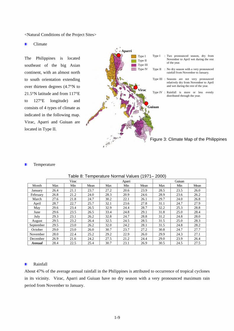
<Natural Conditions of the Project Sites>
Climate
The Philippines is located
southeast of the big Asian
continent, with an almost north
to south orientation extending
over thirteen degrees (4.7°N to
21.5°N latitude and from 117°E
to 127°E longitude) and
consists of 4 types of climate as
indicated in the following map.
Virac, Aparri and Guiuan are
located in Type II.
Temperature
Rainfall
About 47% of the average annual rainfall in the Philippines is attributed to occurrence of tropical cyclones
in its vicinity. Virac, Aparri and Guiuan have no dry season with a very pronounced maximum rain
period from November to January.
Table 8: Temperature Normal Values (1971– 2000) Virac Aparri Guiuan
Month Max Min Mean Max Min Mean Max Min Mean January 26.4 21.1 23.7 27.2 20.6 23.9 28.5 23.5 26.0
February 26.8 21.2 24.0 28.3 20.9 24.6 28.9 23.6 26.2 March 27.6 21.8 24.7 30.2 22.1 26.1 29.7 24.0 26.8 April 28.7 22.7 25.7 32.1 23.6 27.8 31.1 24.7 27.9 May 29.6 23.4 26.5 32.9 24.4 28.7 32.2 25.3 28.8 June 29.6 23.5 26.5 33.4 24.8 29.1 31.8 25.0 28.4 July 29.3 23.1 26.2 32.8 24.7 28.8 31.2 24.8 28.0
August 29.5 23.2 26.4 32.5 24.5 28.5 31.5 25.0 28.3 September 29.5 23.0 26.2 32.0 24.2 28.1 31.5 24.8 28.2
October 29.0 23.0 26.0 30.7 23.7 27.2 30.8 24.7 27.7 November 28.0 22.4 25.2 29.2 22.9 26.0 29.9 24.3 27.1 December 26.9 21.6 24.2 27.5 21.2 24.4 29.0 23.9 26.4 Annual 28.4 22.5 25.4 30.7 23.1 26.9 30.5 24.5 27.5
Type I
Type II
Type III
Type IV
Virac
Guiuan
Aparri
Type I : Two pronounced season, dry from November to April wet during the rest of the year.
Type II : No dry season with a very pronounced rainfall from November to January.
Type III : Seasons are not very pronounced relatively dry from November to April and wet during the rest of the year.
Type IV : Rainfall is more or less evenly distributed through the year.
Figure 3: Climate Map of the Philippines

1-10
Lightning
Southeast Asia including the Philippines, Central Africa and
Central American-Northern South America located in the
southern and northern latitude of 30 degrees has the greatest
concentration of occurrence of lightning in the world.
Table 9: Thunderstorm and Lightning Normal Values (1971 - 2000) Virac Aparri Guiuan
Month Thunderstorm Lightning Thunderstorm Lightning Thunderstorm Lightning January 0 0 0 0 0 1
February 0 0 0 0 0 1 March 0 0 0 0 1 2 April 2 2 3 2 2 5 May 7 10 8 9 3 13 June 8 13 10 14 5 18 July 10 13 8 13 8 20
August 7 11 7 9 7 18 September 10 14 5 9 9 20
October 8 10 2 5 6 18 November 3 4 1 1 4 11 December 1 1 0 0 2 5 Annual 56 78 44 62 47 132
Figure 5: Lightning-prone Area
Figure 4: Virac, Aparri and Guiuan Monthly Mean Rainfall of 2001-2007
0
100
200
300
400
500
600
700
800
Jan Feb Mar Apr May Jun Jul Aug Sep Oct Nov Dec
An
nu
al R
ain
fall
(mm
)
Virac
Aparri
Guiuan

1-11
Tropical Cyclone
For the past 60 years, an average of 19 to 20
tropical cyclones per year occurred in the
Philippine Area of Responsibility (PAR). An
annual average of 8 to 9 tropical cyclones
made landfall/crossed the country. Tropical
cyclones generate extensive damage in the
Philippines.
Earthquake
The Philippines consists of 7,107 islands. The archipelago, like that of Japan, is characterized by
subduction-related volcanic belts with many active volcanoes and experiences frequent seismic activity.
The Philippines, being situated in a zone where at least three lithospheric plates coalesce, hosts more than
200 volcanoes distributed in five volcanic belts intimately related to subduction/convergent processes and
at least 5 imperceptible to perceptible earthquakes occur everyday.
Topographic and Geotechnical Surveys
At Virac, Aparri and Guiuan Meteorological Radar Observation Stations, the topographic and
geotechnical surveys indicated in the following tables were implemented by a local contractor consigned
by the Basic Design Study Team.
Figure 6: Frequency of Tropical Cyclone passage over each Geographical Zone in the Philippines
5 cyclones in 2 years
2 cyclones per year
5 cyclones in 3 years
3 cyclones in 2 years
1 cyclone per year
1 cyclone in 12 years

1-12
<Geotechnical Survey Results>
Table 12: Geotechnical Survey Result of Virac Meteorological Radar Observation Station Boring Depth (m) Soil Type USCS N-value Unit Weight (g/cc) Friction Angle (dgree) Cohesion (kPa)
BH-1
0-8 Clayey silt 10 1.70 - 60 8-18 Sandy silt/Silty clay 26 1.86 - 150 18-19 Clayey gravel 70 1.90 40 - 19-21 Rock Coring - 45 -
BH-2
0-8 Clay 9 1.70 - 50 8-15 Clay/Clayey silt/Sandy silt 34 1.90 - 200 15-22 Weathered rock coring - 40 -
23 Rock 45 -
BH-3
0-15 Clayey silt/Clay 12 1.72 - 75 15-19 Clay 39 1.90 - 200
19-21.5 Weathered rock Coring - 40 - 22 Rock Coring - 45 -
Table 10: Topographic Survey
Required Works
Plane surveying (0.5m contour line) - Position of the existing building, observation facility, observation field - Position of the existing facilities (electrical lines, water lines, telephone lines, sewage, public
roads, fences, vegetation, trees: more than 4m height, streetlights, manholes and other features) - Bearing survey of the magnetic north - Calculation of the area planned
Longitudinal profile and cross section - Indication of ground level at intervals of 10m - Public roads, ponds, river and each water level - Setting bench marks
Required Products
Plane surveying map
Longitudinal profile and cross section
AutoCAD data file in CD-ROM
Table 11: Geotechnical Survey
Boring (All core boring)
Required number of borings: 3 Required depth of borings: 30m (Borings shall be continued to extend to suitable bearing layer for a building construction, even if borings have reached more than a depth of 30m. After reaching the bearing layer, borings shall be continued to a depth of at least 3m. )
Collecting soil samples Undisturbed soil sampling: 3 samples (at different level) x 3 holes Disturbed soil sampling: 3 samples (at different level) x 3 holes Adoption of standard: ASTM or JGS-Japanese geotechnical society
Standard Penetration Test At intervals of every 1m till the bottom of each borehole
Laboratory Testing Density Test of Soil Particle, Particle Size Distribution, Specific Gravity, Water Content , Liquid Limits, Plastic Limits, Unconfined Compression Test and Consolidation Test
Required Products Geotechnical Survey Report: expected soil bearing capacity and calculation of consolidation coefficient

1-13
Table 13: Geotechnical Survey Result of Aparri Meteorological Radar Observation Station Boring Depth (m) Soil Type USCS N-value Unit Weight (g/cc) Friction Angle (dgree) Cohesion (kPa)
BH-1
0-6 Silty sand 9 1.70 26 - 6-14 Silty sand to poorly graded sand 23 1.76 32 - 14-19 Silty clay/Clayey silt 7 1.70 - 40 19-24 Highly plastic clay 21 1.80 - 250 24-32 Poorly graded sand 60 2.00 40 -
BH-2
0-6 Silty sand 11 1.70 26 - 6-9 Silty sand 31 1.82 34 -
9-18 Silty clay/Clayey silt 9 1.76 - 50 18-22 Silty clay 14 1.76 - 90 22-24 Silty sand to poorly graded sand 27 1.80 33 - 24-30 Clayey sand/Silty sand 60 2.00 40 -
BH-3 0-10 Silty sand to poorly graded sand 12 1.70 26 - 10-23 Silty clay/Highly plastic clay 9 1.76 - 50 23-32 Silty sand 60 2.00 40 -
Table 14: Geotechnical Survey Result of Guiuan Meteorological Radar Observation StationBoring Depth (m) N-value Unit Weight (g/cc) Absorption (%) UCT (kg/cm2)
BH-1
1.5 2.09 4.05 36.9 1.5 3.5 2.22 5.26 85.0 3.5 6.0 2.17 10.70 154.0 6.0 9.0 2.25 5.40 100.0 9.0
11.0 2.24 2.63 138.0 11.0 12.0 2.31 3.90 69.0 12.0
16.5 2.27 4.11 49.0 16.5 21.0 2.19 5.40 120.0 21.0
BH-2
3.0 2.36 4.76 49.0 3.0 4.5 2.27 6.80 63.0 4.5 5.0 2.28 6.80 139.0 5.0 9.0 2.20 9.60 153.0 9.0
17.0 2.34 5.00 110.0 17.0 20.0 2.30 3.17 176.0 20.0
BH-3
2.0 2.16 8.80 62.0 2.0 3.0 2.19 3.90 131.0 3.0 6.0 2.21 5.70 63.0 6.0 9.0 2.17 5.56 119.0 9.0
12.5 2.18 5.40 99.0 12.5 16.0 2.21 6.94 72.0 16.0
<Consideration for Environmental Conservation>
Virac, Aparri and Guiuan Meteorological Radar Observation Stations are existing observatories of
PAGASA, and are not covered by the Environmental Impact Statement (EIS) System which consequently
is not required to secure an Environmental Compliance Certificate (ECC). Instead, a Certificate of Non-
Coverage (CNC) to be issued by the Environmental Management Bureau (EMB) is required. PAGASA
completed all the procedures in early May 2008, and has already obtained CNC on May 26, 2008.

Chapter 2 Contents of the Project

2-1
Chapter 2 Contents of the Project
2-1 Basic Concept of the Project
The Philippine archipelago is one of the worst-hit countries by catastrophic tropical cyclones in the world.
It is in the direct path of seasonal typhoons which bring floods, storm surges, and their attendant landslides
and other forms of devastation. The National Disaster Coordinating Council (NDCC) record says that
approximately the number of dead, injured and missing people is in the vicinity of twelve thousand, and
the number of disaster victims is estimated to be around 49 million for the last 10 years between 1998 and
2007. The devastation from tropical cyclones and sever weather disturbances has accounted for 92.5% of
the total damage from natural disasters. Every year, the Philippines seriously experience huge economic
losses coupled with human anguish and sufferings generated by destructive tropical cyclones that cross the
country. They have caused significant damage to agriculture which is a vital industry in the Philippines,
thereby inflicting widespread poverty on its people. The extensive damage from tropical cyclones is a
determining factor for the significant set-back of the national economy. They adversely affect the people’s
standard of living. To alleviate and proactively deal with the situations indicated above, establishment of
effective countermeasures against natural disasters resulting from tropical cyclones is of pressing urgency.
The existing Virac, Aparri and Guiuan meteorological radar systems were completed in 1994 financed by
the Japanese soft loan. Those three radar systems are located at the most strategic places for monitoring
tropical cyclones generated in the Pacific Ocean, and are now more than 15 years old. Because of the age
of the existing radar systems, frequent repairs are required. However, it has become very difficult to
procure the required spare parts making it an extremely difficult job even for the experienced PAGASA
engineers to operate, maintain and repair the radar systems. Therefore, currently PAGASA is not able to
appropriately detect tropical cyclones and locate cyclone centers or intensities.
The activities of the government agencies concerned with disaster management in close coordination and
partnership with the local government units and the mass media mainly with their role in disaster
management in the Philippines (especially in relation to the quick and timely evacuation of residents and
disaster prevention countermeasures) depend almost entirely on the public storm signal warning and
tropical cyclone information from PAGASA. Therefore, deterioration in the quality and accuracy of
PAGASA’s warnings and advisories create significant obstacle for the effective disaster management
system of the Philippines. Under these circumstances, rehabilitation and strengthening of the cyclone
monitoring capability of PAGASA by replacing the existing Virac, Aparri and Guiuan meteorological
radar systems has become an urgent task.
Therefore, the key objective of the Project is the effective mitigation of the devastation caused by tropical
cyclones and other severe weather phenomena, thereby protecting lives and properties via enhancement of

2-2
the capability of PAGASA in tropical cyclone monitoring, especially those that cross the country from the
Pacific Ocean. In order to achieve such objective, the planned project components are;
i) replacement of the existing Virac, Aparri and Guiuan meteorological radar systems,
ii) construction of radar tower buildings at Virac, Aparri and Guiuan Meteorological Radar Observation
Stations,
iii) installation of meteorological data display systems at each Meteorological Radar Observation Station
and the WFFC, and
iv) establishment of meteorological data satellite communication systems (VSAT) connecting between
the Meteorological Radar Observation Stations and the WFFC.
2-2 Basic Design of the Requested Japanese Assistance
2-2-1 Design Policy
(1) Basic Design Policy of the Project
a) To design a meteorological observation system to contribute to disaster prevention.
b) To enable PAGASA to provide weather information, forecasts, advisories and warnings necessary
for the mitigation and prevention of natural disasters and improvement of socio-economic
conditions.
c) To enable PAGASA to monitor weather conditions round-the-clock on a real time basis.
d) To enable PAGASA to promptly issue the public storm signal warning and tropical cyclone
information to the public.
e) To ensure improvement of PAGASA's overall function and capacity in reducing human loss and
economic setback brought about by tropical cyclone disasters through the upgrading of
PAGASA's tropical cyclone monitoring capabilities.
f) To determine and set up the size and components of the Project to match with the technical,
operational and maintenance capabilities of PAGASA.
(2) Design Policy
[1] Design Policy of the Equipment
a) To cover the areas of tropical cyclones coming into the Philippines by three (3) new
meteorological radar systems to be installed at the existing PAGASA meteorological radar
observation stations.

2-3
b) To ensure the equipment is compatible with and meets the technical requirements of the World
Meteorological Organization (WMO) since the Philippines is a member of WMO.
c) To ensure the equipment is suitable for the routine observation and forecasting work of PAGASA.
d) To design the radar systems with functions of having quantitative rainfall observation and air-
turbulence observation capabilities that enhances and upgrades accuracy of weather forecasts by
PAGASA.
e) To design the radar systems to get constant altitude information from 3-dimensional raw data
obtained by scans of the radar systems at multiple elevations for ensuring wider covering range
and detecting rainfall distribution at each altitude.
f) To design that all of the meteorological radar data produced are delivered to the WFFC every 15
minutes by high-speed satellite communications for enabling the timely dissemination of the
tropical cyclone forecasts.
g) To design that a composite radar picture of precipitation intensity in the observation range of the three
(3) meteorological radar systems is prepared by a computer system to be installed in the WFFC.
h) To design the system so that it is within PAGASA’s capability to operate, maintain and repair.
i) To select equipment for which spare parts and consumables can be easily procured and replaced.
j) To select reliable and durable equipment suitable for the local environment.
k) To minimize the recurrent costs to PAGASA for the operation, maintenance and repair of the
equipment.
l) To design the equipment by adjusting the accuracy of radar data through calibration.
m) To design the equipment to minimize lightning damage.
n) To design the equipment to operate using 240V±20%, 3-Phase 3-Wire, 60Hz power.
[2] Design Policy of Radar Tower Building
The design policy is to create buildings suitable for use as meteorological radar facility and to become
an operational base for weather observation. The plan is to construct meteorological radar tower
buildings that will ensure appropriate and effective operations and will accommodate the required
systems, equipment and personnel. It is a basic policy that the designed Radar Tower Buildings satisfy
the following requirements.
a. To design the height of the radar tower buildings for construction to be free of the influence of the
surrounding mountains and existing facilities creating the blind areas for radar observations.
b. To select the most suitable foundation structures to ensure that the permissible horizontal
deflection of the building is not more than 0.075 degree.
c. To adopt the basic wind speed and the seismic zone factor indicated in the “National Structural
Code of the Philippines” based on 50-year mean recurrence interval to the structural design.

2-4
d. To provide the necessary environment for PAGASA’s 24hours/day work schedule of observations
to be performed effectively and efficiently.
e. To have the necessary power supply back-up equipment (diesel generator, radar power backup
unit, auto voltage regulator, etc.) for performing round-the-clock meteorological services 24 hours
a day, 365 days a year.
f. To be sufficiently robust to withstand extreme weather and allow the performance of
uninterrupted radar observation and the supply of weather forecast & warnings, even during a
natural disaster.
g. To make use of local building materials for easy maintenance of the radar tower buildings by
PAGASA.
h. To design the equipment to minimize lightning damage.
(3) Design Policy on Environmental Conditions
1) Temperature
Air-conditioning systems are required for rooms where the equipment is to be installed since Virac,
Aparri and Guiuan have a high temperature and high humid climate.
2) Rainfall
The maintenance stair-case has been located at the center of the building, covered by the upper concrete
slab, to enable PAGASA personnel to easily reach each room for regular maintenance of the radar
equipment without getting wet during raining.
3) Lightning
The frequent lightning occurs especially during the rainy season. A lightning protector is, therefore
planned, to prevent damage to the building and to the equipment.
4) Tropical Cyclone (Stormy Wind)
To ensure highly accurate radar observations, in accordance with the “National Structural Code of the
Philippines”, the maximum horizontal movement angle of the buildings must be not more than 0.075
degree at the survival wind velocity of 250km/h (approx. 69m/s) in Virac, Aparri and Guiuan.
5) Earthquake
According to the “National Structural Code of the Philippines”, Virac, Aparri and Guiuan are located in
“Zone 4”. The “Seismic Zone Factor” of Zone 4 is defined z = 0.4 indicated in the Code will be
incorporated into the structural design and calculation for the radar tower buildings.
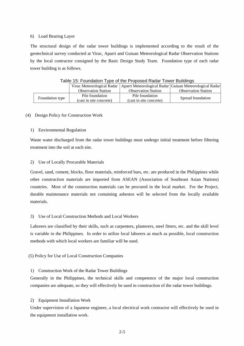
2-5
6) Load Bearing Layer
The structural design of the radar tower buildings is implemented according to the result of the
geotechnical survey conducted at Virac, Aparri and Guiuan Meteorological Radar Observation Stations
by the local contractor consigned by the Basic Design Study Team. Foundation type of each radar
tower building is as follows.
Table 15: Foundation Type of the Proposed Radar Tower Buildings
Virac Meteorological Radar Observation Station
Aparri Meteorological Radar Observation Station
Guiuan Meteorological Radar Observation Station
Foundation type Pile foundation
(cast in site concrete) Pile foundation
(cast in site concrete) Spread foundation
(4) Design Policy for Construction Work
1) Environmental Regulation
Waste water discharged from the radar tower buildings must undergo initial treatment before filtering
treatment into the soil at each site.
2) Use of Locally Procurable Materials
Gravel, sand, cement, blocks, floor materials, reinforced bars, etc. are produced in the Philippines while
other construction materials are imported from ASEAN (Association of Southeast Asian Nations)
countries. Most of the construction materials can be procured in the local market. For the Project,
durable maintenance materials not containing asbestos will be selected from the locally available
materials.
3) Use of Local Construction Methods and Local Workers
Laborers are classified by their skills, such as carpenters, plasterers, steel fitters, etc. and the skill level
is variable in the Philippines. In order to utilize local laborers as much as possible, local construction
methods with which local workers are familiar will be used.
(5) Policy for Use of Local Construction Companies
1) Construction Work of the Radar Tower Buildings
Generally in the Philippines, the technical skills and competence of the major local construction
companies are adequate, so they will effectively be used in construction of the radar tower buildings.
2) Equipment Installation Work
Under supervision of a Japanese engineer, a local electrical work contractor will effectively be used in
the equipment installation work.

2-6
(6) Design Considerations to Simplify Operation and Maintenance for PAGASA
1) Easy to operate the equipment
The equipment to be supplied under the Project is to be used to support PAGASA’s routine works as the
national meteorological agency for the meteorological disaster prevention. A variety of data processing,
analysis, display and communications capabilities must be readily available for PAGASA, using simple
operational procedures.
2) Easy maintenance and affordable recurrent costs of the equipment
The equipment must be designed to minimize the spare parts and consumables required and to simplify
regular maintenance. Replacement parts must be quickly and readily available. The biggest recurrent
cost of the Project is expected to be electricity, therefore the equipment and facilities should be designed
to minimize power consumption.
3) Consideration of minimizing operation & maintenance costs
In order for PAGASA to meet the increased ongoing costs of the system, such as operation and
maintenance costs, after the completion of the Project, the following measures have been included in
planning for the equipment and the radar tower buildings.
The ability to restrict the operation of air-conditioning systems and the electricity supply to the
operational rooms in the radar tower buildings
The utilization of natural light to reduce energy requirements by minimizing the hours of artificial
lighting required.
The incorporation of solid-state parts into the radar system as much as possible to reduce the cost
and frequency of parts replacement.
(7) Design Policy for Equipment & Building Grade
To allow the supply of uninterrupted forecasts and warnings to the public, even during tropical cyclone
crossing the country, the equipment and buildings must be sufficiently robust to withstand floods, local
severe storms and lightning strikes and enable the provision of meteorological services 24 hours per day.
(8) Design Policy regarding Construction/Procurement Method and Schedule
Locally procurable materials and the local construction methods must be used in the building design.
The equipment to be installed in the radar tower buildings such as specialized power backup systems and
meteorological equipment is not available in the local market. The pulse compression solid state

2-7
Doppler radar system which has already been put into practical use for meteorological observation and
has confirmed its reliability, durability, accuracy and performance is only available and made in Japan.
The equipment for the Project must be durable, reliable, of a high technical level, and cost effective.
In accordance with the priority of the project sites (1: Virac, 2: Aparri and 3: Guiuan) indicated by
PAGASA and as a result of the study on the climate conditions, the Project will be implemented one site
at a time and operation of 2 existing/new radar systems must be kept during the Project implementation
for monitoring tropical cyclones.
2-2-2 Basic Plan
The finalized components in the basic design for the Project are as follows.
According to the design policies aforesaid, the basic design plan of the Equipment and the Radar Tower
Buildings are clarified below.
(1) Basic Plan of the Equipment
1) Meteorological Radar System
A meteorological radar system is the only system able to observe in real time the occurrence, movement,
distribution and intensity of rainfall, and meteorological phenomena related to rainfall, and to provide
quantitative measurements over a large area in real time.
The requested meteorological radar systems for Virac, Aparri and Guiuan are S band. S band radar
system is the most suitable type of radar system for the observation of precipitation over a very wide
area. S band radar system has several important characteristics, including lower attenuation by rain and
the atmosphere than other types of radar, and the ability to transmit at high power, providing a “long
range”, “real time” system. For these reasons, S band radar has been selected as the most suitable to
monitor large-scale and distant phenomena such as tropical cyclones. In addition, the S band radar
Table 16: Finalized Components for the Project
Component WFFC
Virac Meteorological
Radar Observation Station
Aparri Meteorological
Radar Observation Station
Guiuan Meteorological
Radar Observation Station
Equipment Procurement and Installation Meteorological Radar System - 1 1 1 Meteorological Radar Data Display System 1 1 1 1 Meteorological Data Satellite Communication System (VSAT) 1 (Hub) 1 1 1
Facility Construction Radar Tower Building (including furniture for Equipment) - 1 1 1

2-8
system must be a Doppler system with a changeable function having quantitative rainfall observation
and air-turbulence observation capability in real time.
The existing 2,850MHz ±5MHz frequency band will be used for the proposed Doppler radar systems
supplied under the Project. Technical features of the S band meteorological Doppler radar system are as
follows.
Table 17: Major Features of Meteorological Radar System Major Features Existing Radar System Proposed Radar System
Main Purpose Tropical Cyclone Monitoring Tropical Cyclone Monitoring
Band S band S band
Frequency 2,850MHz 2,850MHz
Rainfall Resolution 16 gradation level indication 256 gradation level indication
Detectable Range of Precipitation Intensity 1mm/h or more 300km 450km
Doppler Function None Available
Accumulated Rainfall None Available
As indicated in the table attached hereunder, the existing meteorological radar systems can detect a
precipitation rate of 1mm/h or more only within a 300km radius. However, the proposed
meteorological Doppler radar system is designed to be able to detect a precipitation rate of 1mm/h or
more within a 450km radius.

2-9
Table 18: Comparison of Precipitation Detection Range between the existing radar systems and the proposed radar systems
by Reception Power (dbm) Precipitation IntensityDetection Range of the Existing Radar System (Antenna Diameter: 4m)
Reception Power: -110dBmDistance
(km) Precipitation Intensity (mm/h)
0.50 1.00 5.00 10.00 20.00 40.00 100.0010 -80.5 -75.7 -64.5 -59.7 -54.9 -50.1 -43.750 -94.9 -90.1 -78.9 -74.1 -69.3 -64.5 -58.1
100 -101.4 -96.6 -85.4 -80.6 -75.8 -71.0 -64.6150 -105.5 -100.7 -89.5 -84.7 -79.8 -75.0 -68.7200 -108.5 -103.7 -92.5 -87.7 -82.8 -78.0 -71.7250 -110.9 -106.1 -94.9 -90.1 -85.3 -80.5 -74.1300 -113.0 -108.2 -97.0 -92.2 -87.4 -82.5 -76.2350 -114.8 -110.0 -98.8 -94.0 -89.2 -84.4 -78.0400 -116.5 -111.7 -100.5 -95.7 -90.9 -86.0 -79.7450 -118.0 -113.2 -102.0 -97.2 -92.4 -87.6 -81.2
Detection Range of the proposed Radar System (Antenna Diameter: 5m) Reception Power: -110dBm
Distance (km)
Precipitation Intensity (mm/h) 0.50 1.00 5.00 10.00 20.00 40.00 100.00
10 -75.4 -70.5 -59.4 -54.5 -97.4 -44.9 -38.550 -89.7 -84.9 -73.7 -68.9 -64.1 -59.3 -52.9
100 -96.3 -91.4 -80.3 -75.4 -70.6 -65.8 -59.4150 -100.3 -95.5 -84.3 -79.5 -74.6 -69.8 -63.5200 -103.3 -98.5 -87.3 -82.5 -77.6 -72.8 -66.5250 -105.7 -100.9 -89.7 -84.9 -80.1 -75.3 -68.9300 -107.8 -103.0 -91.8 -87.0 -82.2 -77.4 -71.0350 -109.6 -104.8 -93.6 -88.8 -84.0 -79.2 -72.8400 -111.3 -106.5 -95.3 -90.5 -85.7 -80.9 -74.5450 -112.8 -108.0 -96.8 -92.0 -87.2 -82.4 -76.0
In order to accomplish the project targets, the proposed radar systems must meet the following
requirements.
[1] Doppler Mode
The meteorological radar system is designed to work in Doppler mode, which detects the wind motion
and wind patterns of severe weather phenomena such as tropical cyclones, local sever storms and
tornadoes within a 200km radius. This will help PAGASA to monitor the movement and the
development of severe weather system for the preparation of more accurate and timely weather
forecasting and warning. The Doppler mode is essential to allow for more accurate forecasting and
longer forecast prediction times.
[2] CAPPI (Constant Altitude PPI (Plan Position Indicator)) Mode
CAPPI is a horizontal cross-section display at an altitude which can be specified by the user. It is
Out of Range New Area of Detection Reliable Detection Range

2-10
derived from the interpolation of volumetric data. Data from all azimuth and elevation points are used
in the calculation of precipitation intensity in order to generate the display for a specified altitude. The
product displays constant altitude information from 3-dimensional raw data obtained by scans at
multiple elevations. To get 3 dimensional data, the radar antenna can operate in "volumetric scan"
mode, changing the antenna elevation at regular time intervals. For the estimation of rainfall from a
convective system and the preparation of composite pictures using multiple radar systems, accurate
observed data, especially CAPPI data at an altitude of 2km or 3km, is required. An automatic multi-
level CAPPI function will be provided with the proposed radar systems.
[3] Required Radar Display and Output Information Functions
The following functionality must be provided by the meteorological Doppler radar system to enable
PAGASA to accomplish its role as a national meteorological service.
Table 19: Required Radar Display and Output Information Functions
Radar Display and Output Information Functions Purpose of
Observation
Necessary Data for Tropical Cyclone
Monitoring
Necessary Data for Improvement of
Forecast Accuracy 1 PPI Display
Rainfall
○ ○
2 RHI Display ○
3 JPG Image Output ○ ○
4 Cyclone Tracking Display and Forecast ○ ○
5 Heavy Rainfall Warning Output ○ ○
6 Accumulated Rainfall ○ ○
7 Catchment Area Rainfall Amount Display and Warning ○ ○
8 Surface Rain Display ○ ○
9 Composite Picture Display Wind Velocity and
Direction
○ ○
10 Wind Velocity and Direction ○ ○
11 Wind Profile of the Upper Layer ○
12 Wind Shear Alert ○ ○
13 CAPPI Display
3-dimensional
○ ○
14 Echo Tops Display ○
15 Cross Section ○
16 Vertical Integrated Liquid Layer ○
17 3-dimensional data Display ○
“Present Detection Range of the Existing Meteorological Radar Observation Network in the Philippines”
and “Composite Picture of the Proposed Meteorological Radar Observation Network in the Philippine” are
attached hereunder.

2-11
Figure 7: Present Detection Range of the Existing Meteorological Radar Observation Network
in the Philippines (The range indicates beam height of 3000m above sea level)
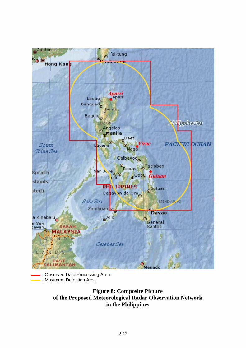
2-12
: Observed Data Processing Area : Maximum Detection Area
Figure 8: Composite Picture of the Proposed Meteorological Radar Observation Network
in the Philippines

2-13
2) Meteorological Radar Data Display System
PAGASA’s forecasters are required to do a substantial amount of work, at a number of locations, very
rapidly, in order to produce the required outputs. Therefore, meteorological radar data display systems
are to be installed at Virac, Aparri and Guiuan Meteorological Radar Tower Buildings to be constructed
in the Project and the WFFC. In addition, the system must have the ability to receive and display all the
meteorological products in real time for routine weather forecasting & warning.
Displays of the system must be minimized heat production for effective room cooling, power-saving
type and less screen reflections for smooth and long time operation.
A composite radar picture of precipitation intensity in the observation range of three (3) meteorological
radar systems will be prepared by a computer system to be installed in the WFFC. Data file of the
composite radar picture will be stored as binary data of hourly accumulated precipitation data of 2.5 km
mesh in the detection range shown in the last page. The meteorological radar data display system will
be designed to enable the WFFC to manually input the hourly accumulated precipitation data of 2.5 km
mesh to the existing flood forecasting model of PAGASA.
3) Meteorological Data Satellite Communication System (VSAT)
In order to improve the tropical cyclone monitoring and forecasting work, enabling the timely
dissemination of products, all of the meteorological radar data produced by the proposed Virac, Aparri
and Guiuan Meteorological Radar Systems must be delivered to the WFFC, every 15 minutes in view of
CAPPI mode observation. The required data transmission speed is 32kbps or more between Virac,
Aparri and Guiuan Meteorological Radar Systems and the WFFC. To do this, a data acquisition system
is required, employing the most suitable band for high-speed satellite communication links using C-
band, because of its low attenuation by rain.
Output Power
Frequency
FEC: 3/4
Bit Rate: 64kbps FEC: 1/2
PAGASA Head Office
WFFC
Band Width 117.2 kHz
Other User
5kHz
Other User Virac Aparri Guiuan
Band Width70.4 kHz
Band Width70.4 kHz
Band Width70.4 kHz
Bit Rate: 64kbps
Bit Rate: 64kbpsFEC: 3/4
FEC: 3/4
5kHz 5kHz 2kHz 2kHz 2kHz Guard Band
Bit Rate: 64kbps
5kHz
Figure 9: Estimation of Minimum Required Space Segment

2-14
The required transmission time for the radar products to be transmitted by the Meteorological Data
Satellite Communication System (VSAT) from Virac, Aparri and Guiuan Meteorological Radar Systems
to the WFFC is indicated in the following tables.
Table 20: Required Transmission Time at Transmission Speed 64kbps
Meteorological Radar Data Data Transmission
Time to WFFC Total Required Time
Intensity RAW Data and Doppler RAW Data for a Fixed Elevation Angle (481kBytes)
1.3min ⇒ 13.8min ⇒ 15min
Intensity RAW Data and Doppler RAW Data for 10 elevation Angle (4.81MBytes)
12.5min
Table 21: Data Volume and Products of the Proposed Meteorological Radar System Descriptions of Data Data Volume of Single Observation Radar Display
Intensity RAW Data and Doppler RAW Data for a Fixed Elevation Angle
[8bit Intensity] [Doppler] Short pulse Long pulse
Short Pulse Observation Data ・ R-θ data ・ 320range x 360 angle ・ 8bit data (Intensity /Doppler)
Sub-total: 230.4kbytes Long Pulse Observation Data ・ R-θ data ・ 320range x 360 angle ・ 8bit data (Intensity /Doppler)
Sub-total: 230.4kbytes Header:5.12kbyte x 4
=20.48kbytes Total: 481kbytes
<Radar Products> ・PPI/RHI Display ・Cyclone Tracking Indication and
Forecast ・Wad Velocity and Direction ・Wind Shear Alert
Intensity RAW Data and Doppler RAW Data for Multi-elevation (10 elevation) Angle
[8bit Intensity] [Doppler] Short pulse
Long Pulse
Short Pulse Observation Data ・ R-θ data ・ 320range x 360 angle ・ 8bit data (Intensity /Doppler) ・ 10 elevation angle
Subtotal: 2.304Mbytes Short Pulse Observation Data ・ R-θ data ・ 320range x 360 angle ・ 8bit data (Intensity /Doppler) ・ 10 elevation angle
Subtotal: 2.304Mbytes Header: 5.12kbyte x 40
=204.8kbytes Total: 4.81Mbytes
<Radar Products> ・PPI/RHI Display ・Cyclone Tracking Indication and
Forecast ・Wad Velocity and Direction ・Wind Shear Alert ・CAPPI Display ・Heavy Rainfall Warning Output ・N-hour Accumulated Rainfall ・Vertical Integrated Liquidation ・Surface Rain Indication ・Composite Display ・3-Dimensional Data Display ・Vertical Cross Section ・Echo Top Display ・Wind Profile of the Upper Layer ・Catchment Area Rainfall Amount
Display
For transmitting all the meteorological radar data from Virac, Aparri and Guiuan Meteorological Radar
Systems to the WFFC, the transponder to be selected for the Project must satisfy the following
requirements.
Geographic Coverage : Southeast Asia area including Philippines

2-15
Satellite Beam : C band beam
Frequency : Up Link 5850MHz - 6425MHz
Down Link : 3625MHz - 4200MHz
Polarizations : Orthogonal Linear
Satellite EIRP (Max) : more than 41 [dBW]
Satellite G/T : more than 2.0 [dB/K]
Satellite SFD : less than -86.5 [dBW/m2]
Satellite Orbital Slot : 87°E - 156°E
<EIPR>
Effective Isotropic Radiated Power – This term describes the strength of the signal leaving the satellite
antenna or the transmitting earth station antenna, i.e., final amplifier output power + antenna gain in
dB. The unit dBW is the logarithmic expression of Power in Watt.
<G/T>
G/T is called “Figure of merit” and represents the receive system performance. G/T is the ratio of the
receive antenna gain and the system thermal noise including the antenna noise.
<SFD – Saturation Flux Density>
This means the flux density at the satellite receive antenna required to saturate a satellite transponder.
The “Schematic Diagram for the Project for Establishment of the Meteorological Radar System in the
Philippines” is attached hereto.

VSAT
VSAT Communication
Network
Schematic Diagram of Meteorological Radar Network
AC 220V, 3Ф3W
Radar Power Maintenance Panel
Virac Meteorological Radar Observation Station
Compact UPS
VSAT In-Door Unit (IDU)
DataAnalyzing
Unit
Data & Protocol Converter
Cyclone Tracking Monitor
IsolationTransformer
ChangeoverSwitch
CommercialPower
Diesel Generator
Power Supply Capacitor
Radar TASK Controller
Color Printer Telephone
Dual Optical Repeater
Observation RoomData Analysis Room
Radome
VoIP Gateway
Electricity Room
Antenna
Dual Switch
VSAT Out-Door Unit
(ODU/LNB&Transmitter)
VSAT Antenna
Color Printer
Severe Storm and Doppler Velocity
Indicator
*1) DRSP : Digital Receiver and Signal Processor
Dual Optical
Repeater
Color Printer Dual
Switch
Radar Equipment Room
Compact UPS
Dual Switch
Compact UPS
Compact UPS
Compact UPS
Compact UPS
Power Supply Room
Telephone
VoIP Gateway
DVD DVD
Transmitter
DehydratorAntenna
Controller DRSP(*1)
VoIP Gateway
Telephone
Off-line Maintenance Computer
GPRS/EDGEModem
Compact UPS
Radar Power Maintenance Panel
Compact UPS
VSAT In-Door Unit (IDU)
DataAnalyzing
Unit
Data & Protocol Converter
Cyclone Tracking Monitor
Radar TASK Controller
Color Printer Telephone
Dual Optical Repeater
Observation RoomData Analysis Room
Radome
VoIP Gateway
Antenna
Dual Switch
VSAT Out-Door Unit
(ODU/LNB&Transmitter)
VSAT Antenna
Color Printer
Severe Storm and Doppler Velocity
IndicatorDual
Optical Repeater
Color Printer Dual
Switch
Radar Equipment Room
Compact UPS
Dual Switch
Compact UPS
Compact UPS
Compact UPS
Compact UPS
Telephone
VoIP Gateway
DVD DVD
Transmitter
DehydratorAntenna
Controller DRSP(*1)
VoIP Gateway
Telephone
Off-line Maintenance Computer
GPRS/EDGEModem
Compact UPS
Radar Power Maintenance Panel
Guiuan Meteorological Radar Observation Station
Compact UPS
VSAT In-Door Unit (IDU)
DataAnalyzing
Unit
Data & Protocol Converter
Cyclone Tracking Monitor
Radar TASK Controller
Color Printer Telephone
Dual Optical Repeater
Observation RoomData Analysis Room
Radome
VoIP Gateway
Antenna
Dual Switch
VSAT Out-Door Unit
(ODU/LNB&Transmitter)
VSAT Antenna
Color Printer
Severe Storm and Doppler Velocity
IndicatorDual
Optical Repeater
Color Printer Dual
Switch
Radar Equipment Room
Compact UPS
Dual Switch
Compact UPS
Compact UPS
Compact UPS
Compact UPS
Telephone
VoIP Gateway
DVD DVD
Transmitter
DehydratorAntenna
Controller DRSP(*1)
VoIP Gateway
Telephone
Off-line Maintenance Computer
GPRS/EDGEModem
Compact UPS
Aparri Meteorological Radar Observation Station
DDS
DDS
PAGASA Head Office
5kVA AVR
Cyclone Tracking Monitor
Composite Processor
Accumulated Rainfall Processor
Doppler Velocity Indicator
Meteorological Data Archiving Unit
Radar WEB Server
AVR
Product Retrieval Unit
Dual Router
PAGASAInternet Server
HUB VSAT Antenna
VSAT Out-Door Unit (ODU/LNB&Transmitter)
VSAT In-Door Unit (IDU)
Telephone VoIP Gateway
5kVA UPS
Dual Switch
Compact UPS
Compact UPS
AVR
Compact UPS
AVR
Color Printer
Color Printer
Compact UPS
AVR
AVR
AVR
Compact UPS
AVR
Weather and Flood Forecasting Center
Compact UPS
Compact UPS
DVD
DVD
AVR
Compact UPS
Off-line Maintenance Computer
GPRS/EDGE Modem
Emergency Power
Backup unit
AC 220V, 3Ф3W
AutomaticVoltage
Regulator(AVR)
IsolationTransformer
ChangeoverSwitch
CommercialPower
Diesel Generator
Power Supply Capacitor
Electricity Room
*1) DRSP : Digital Receiver and Signal Processor
Power Supply Room
AC 220V, 3Ф3W IsolationTransformer
ChangeoverSwitch
CommercialPower
Diesel Generator
Power Supply Capacitor
Electricity Room
*1) DRSP : Digital Receiver and Signal Processor
Power Supply Room
Emergency Power
Backup unit
Emergency Power
Backup unit
Color Printer
Color Printer
Color Printer
Color Printer
AutomaticVoltage
Regulator(AVR)
AutomaticVoltage
Regulator(AVR)
2-16
Figure 10: Schematic Diagram for the Project for Establishment of the Meteorological Radar System in the Philippines

2-17
(2) Major Equipment List
As a consequence of the basic design study, the major components of the Project are described below.
Table 22: Major Components
Name of System WFFC
Virac Meteorological
Radar Observation
Station
Aparri Meteorological
Radar Observation
Station
Guiuan Meteorological
Radar Observation
Station
Meteorological Radar System - ○ ○ ○
Meteorological Radar Data Display System ○ ○ ○ ○
Meteorological Data Satellite Communication System (VSAT) ○ ○ ○ ○
Major Equipment List
Meteorological Radar System (Virac Meteorological Radar Observation Station)
Name of Site: Virac Meteorological Radar Tower Building (Radome Floor) Equipment Specification Quantity Purpose
Radome Type: Sandwich Type (Spherical surface) Dimension: Approx. 8m diameter Color: White Suitable non-observant and non-water stickling finish for making smooth surface Design Wind Pressure: 370kg/m2 Suitable Frequency: 2,850MHz (±5MHz) Transmission loss: 0.5dB or less on one way path in dry Relative humidity: 0 to 100% Lightning Rod: Protecting angles of 60degree Obstruction light: Waterproof lightning system Base ring including necessary installation materials
1 For protecting the radar antenna assembly (a parabolic dish reflector) and maintenance personnel from severe weather conditions and lightning attacks.
Antenna Type: Horn feed parabolic antenna Reflector: approx. 5m diameter Suitable Frequency: 2,850MHz (±5MHz) Beam width: not wider than 1.7 degree at -3dB point Antenna gain: 39dB or more without Radome Polarization: Linear, horizontal Side lobe level:
not more than -25dB without Radome Pedestal including the motor and rotary joint for azimuth and elevation
Driving range: Azimuth 360 degree, elevation -2 to +90 degree
Safety switch: to inhibit from radiating during maintenance works in Radome
VSWR: not more than 1.4 without Radome Optical connection box:
For converting electric control signal to optical one Directional coupler:
Coupling coefficiency: forward –50dB ±2dB backward –35dB ±1dB
Calibration accuracy: ±0.5dB VSWR: less than 1.10 Rating power: not less than 20kW
1 For radiating radar beam into the atmosphere and receiving scatter waves while rotating the parabola antenna as azimuth and elevation direction.

2-18
Name of Site: Virac Meteorological Radar Tower Building (Radar Equipment Room) Equipment Specification Quantity Purpose
Antenna Controller Control processor: PC-based computer Control mode:
Programming mode and manual control mode Driving method: Servo motor control method Scanning method:
Independently scanning both of azimuth and elevation Driving range:
Azimuth 360 degree, elevation –2 to +90 degree Rotation speed
Azimuth: 0.5 to 6 rpm (6 rpm in operation) , selectable Elevation: not more than 17 second for each way scan between -2 and 60 degree
Automatically and manually capable for clockwise and counterclockwise rotation in AZ and up & down in EL Accuracy of specified angle for both antenna calibration and digital readout:
Azimuth: not more than ±0.1 degree Elevation: not more than ±0.1 degree
Interlock: Protecting overload and overrun of the Antenna Reset switch for EL limit and antenna overrun
Monitor: Real-time indication of the angle of azimuth and elevation
Fitting: Control Card for Antenna Controller (x1)
1 For rotating the parabolic dish reflector and for controlling the antenna in azimuth and elevation by both horizontal and vertical drive motor units.
Transmitter Transmitting frequency: 2,850MHz (±5MHz) Center frequency:
Short range observation by short pulse width: 2,847.5MHz Long range observation by long pulse width: 2,852.5MHz
Transmitting power: 10kW peak (at Tx output) Power amplifier: Solid state type Power amplifier protection:
to inhibit operation individually in case of abnormal high temperature in chassis
Radiation blanking feature: It shall be able to set both azimuth and elevation
Pulse width: from 1µs to 100µs, selectable -Short range observation by short pulse width: from 1µs
to 2µs -Long range observation by long pulse width: from 50µs
to 100µs -Short pulse and long pulse are combined for the
observation period. Pulse repetition frequency (PRF): [Doppler mode: Dual PRF]
From 500Hz to 1,800Hz (Pulse width: 1µs or 50µs) selectable
[Intensity mode: Single PRF] From 250 Hz to 900Hz (Pulse width: 2µs or 100µs) selectable
Duty: less than 7% Status display:
Transmission hour, status of Local/Remote control Alert display:
Transmitting power alarm, Temperature alarm in cabinet
Fitting: Power amplifier unit for transmitter (x2) Control card for transmitter (x1)
1 For amplifying the pulse- modulated power with stable frequency and transmitting the power to the antenna.
2-19
Digital Receiver and Signal Processor (DRSP)
Noise figure of the high frequency circuit: 3dB or better at the input terminal of low noise amplifier (LNA) Pulse compression type: Chirp modulation Pulse Compression ratio: 80 or less Receiver type: Coherent IF digitizer Sensitivity: -110dBm or better (at 10µs plus) Dynamic range: 80dB or better from noise level to the saturated level (depending on matched filter bandwidth) Doppler signal processor (including DSP card and Rx card): Software based controller Quantization: 14 bits Range bin: 1024 Processing area:
(Intensity mode) throughout 0 km to 440 km or more in range and 0 to 360 degree in azimuth (Doppler mode) throughout 0 km to 200 km or more in range and 0 to 360 degree in azimuth
Intensity signal process
-Ground clutter suppression: Frequency analysis by filter-bank and low frequency suppression with minimum influence to precipitation intensity -Logarithmic linearity: within ±1dB throughout 80dB -Range correction: depending on radar equation -Air-attenuation correction: 0.005dB/km in Observation Range
Velocity signal process -Processing type: Pulse Pair, FFT and Random Phase -Velocity De-arising: Real-time processing by Dual-PRF -Trigger control: PRF ratio selectable (2:3, 3:4, 4:5)
Averaging: Block averaging and/or sliding averaging Output data:
Reflectivity (Z), Doppler velocity (V), Spectrum width (W)
Output data resolution: 8bit Output data indicating interval:
within 1 minute after automatic scan Time adjustment:
Automatically adjustment by GPS NTP server (including GPS antenna)
Fitting: Control Card for DRSP (x1)
1 For receiving, pulse compression and processing echo signal from the Antenna. For suppressing unnecessary echo such as clutter signals reflected from the ground. For sending ingest data to radar TASK controller.
Dehydrator Capability of ventilation pressure: 3±1 liter/min, Upper limit: 300 ±30 hPa Lower limit: 70±30 hPa
1 For supplying dried and pressurized air into the wave-guide to reduce wave propagation loss.
Wave-guide Configuration
Wave-guide Type: S-band wave-guide
(conformity with WR-284 or equivalent) Circulator Allowable maximum power: at least 20 kW TR limitter (x6) Type: Dual backup type
1 For feeder line propagation wave traveling between the antenna and TX/RX.

2-20
Radar TASK Controller
CPU: Intel CoreTM2 Duo 2GHz or equivalent Main memory (RAM): 1024Mbytes or more Hard disk unit: 250GBytes or more x two (2) drives CD-RW Drive: one (1) Monitor display: Color LCD type, 19 inches or more LAN interface: IEEE802.3/u/ab, 10BASE-T/100BASE-TX/1000BASE-T, TCP/IP, two (2)ports or more LAN Arrester: for surge protection, RJ45 interface Input power: AC 220V, 60Hz, single phase Software Operating system: UNIX or LINUX-based
Application software: -Radar local control and monitoring -Observation scheduling -Radar echo display -Radar data generation and dissemination
1 For operating the radar system, monitoring condition of the radar system and generating raw product data. Control and monitoring items: Radiate control/status Azimuth/elevation position control/status TX standby status Pulse width control/status Antenna local/maintenance mode status.
Data & Protocol Converter
CPU: Intel CoreTM2 Duo 2GHz or equivalent Main memory (RAM): 1024Mbytes or more Hard disk unit: 250GBytes or more x two (2) drives CD-RW Drive: one (1) Monitor display: Color LCD type, 19 inches or more LAN interface: IEEE802.3/u/ab, 10BASE-T/100BASE-TX/1000BASE-T, TCP/IP, two (2)ports or more LAN Arrester: for surge protection, RJ45 interface Input power: AC 220V, 60Hz, single phase Software Operating system: UNIX or LINUX-based
Application software: -Data receiving, converting and transfer -Parameter setting -Display processing
1 For sending Raw data to central system according to specified interval.
Peripherals Compact UPS -Capacity: 500VA or more -Input power: AC 220V ±15%, single phase, 60Hz -Output power: AC 220V ±5%, single phase, 60Hz -Back-up time: 5 minutes or longer at full load
2 For supplying back-up AC power to computer equipment in order to enable proper shutdown procedure of the system in case of power failure.
Dual Switch -LAN interface: IEEE 802.3 Ethernet -Connection port: 100BASE-TX or more, eight (8)ports or more
-Input power: AC 220V, single phase, 60Hz -Each ports and power supply shall be duplicated
2 For connecting all the computing equipment on LAN.
Color Printer -Color inkjet type, A3 size -At least 1200 dpi resolution, 7ppm of faster printing
speed -Interface USB or LAN -Input power: AC 220V, single phase, 60Hz
1 For printing radar image.
Dual Optical Repeater -LAN interface: IEEE 802.3 Ethernet -Connection port: 100BASE-TX, one (1) port or more, Optical fiber interface one (1) set, Multi-mode (100Mbps)
-Input power: AC 220V, single phase, 60Hz -Each ports and power supply shall be duplicated
1 For converting electrical signal and optical signal on LAN for surge protection.
Radar Power Maintenance Panel -Circuit breaker: no-fuse-breaker type -Main breaker: no-fuse-breaker type or magnetic-breaker-Power distribution: 5 outputs include 1 spare -Input power: AC 220V, three phase, 60Hz -Output power: AC 220V, single phase, 60Hz
1 For distributing and supplying AC power to radar system.

2-21
Name of Site: Virac Meteorological Radar Tower Building (Electricity Room) Equipment Specification Quantity Purpose
Isolation Transformer
Capacity: 35kVA or more Input Power: AC 220V, 240V selectable, three phase three wire, 60Hz Output Power: AC 220V, three phase three wire, 60Hz Insulation: Class B Surge voltage: 30kV or more
1 For protecting each equipment from surge voltage in main power.
Automatic Voltage Regulator (AVR)
Capacity: 30kVA or more Input Power: AC 220V ±20%, three phase three wire, 60Hz
Output Power: AC 220V ±5%, three phase three wire, 60Hz
1 For supplying the constant or regulated voltage to the radar system.
Name of Site: Virac Meteorological Radar Tower Building (Power Supply Room) Equipment Specification Quantity Purpose
Power Supply Capacitor
Capability: 15kVA or more Input voltage:
AC 220V±10% (three phase three wire, 60Hz) Normal output: Direct output of input voltage CVCF output:
AC 220V ±5% (three phase three wire, 60Hz) Back up time: 4 minutes or longer for radar equipment Energy storage: Electric double layer capacitor Others: Bypass function
1 For supplying the uninterrupted power by Electric Dual Layer Capacitor energy to the radar system when power failure occurres.
Name of Site: Virac Meteorological Radar Tower Building (Maintenance Room) Equipment Specification Quantity Purpose
Test Instruments and Materials
Test signal Generator 1 set For maintenance of radar system. Power Meter 1 set Power Sensor 1 set Frequency Counter 1 set Detector 1 set Attenuator Set 1 set Terminator for Detector 1 set Oscilloscope 1 set Digital Multimeter 1 set CW Converter 1 set Network Camera 1 set Tool Kit 1 set Extension Cable 1 set Leveler 1 set Step Ladder 1 set Clump Current Meter 1 set Vacuum Cleaner 1 set Radar Antenna Maintenance Deck 1 set
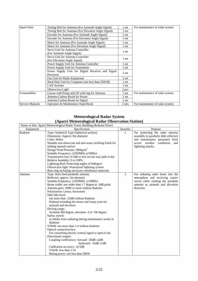
2-22
Spare Parts Timing Belt for Antenna (For Azimuth Angle Signal) 1 set For maintenance of radar system. Timing Belt for Antenna (For Elevation Angle Signal) 1 set Encoder for Antenna (For Azimuth Angle Signal) 1 set Encoder for Antenna (For Elevation Angle Signal) 1 set
Motor for Antenna (For Azimuth Angle Signal) 1 set Motor for Antenna (For Elevation Angle Signal) 1 set Servo Unit for Antenna Controller (For Azimuth Angle Signal)
1 set
Servo Unit for Antenna Controller (For Elevation Angle Signal)
1 set
Power Supply Unit for Antenna Controller 1 set Power Supply Unit for Transmitter 1 set Power Supply Unit for Digital Receiver and Signal Processor
1 set
Fan Unit for Radar Equipment 2 set Hard Disk Unit for Computer (not less than 250GB) 1 set LAN Arrester 1 set Obstruction Light 2 pcs
Consumables Grease with Pump and Oil with Jug for Antenna 1 set For maintenance of radar system. Antenna Carbon Brush for Power 1 set Antenna Carbon Brush for Signal 1 set
Service Manuals Operation & Maintenance Hand Book 2 sets For maintenance of radar system.
Meteorological Radar System (Aparri Meteorological Radar Observation Station)
Name of Site: Aparri Meteorological Radar Tower Building (Radome Floor) Equipment Specification Quantity Purpose
Radome Type: Sandwich Type (Spherical surface) Dimension: Approx. 8m diameter Color: White Suitable non-observant and non-water stickling finish for making smooth surface Design Wind Pressure: 380kg/m2 Suitable Frequency: 2,850MHz (±5MHz) Transmission loss: 0.5dB or less on one way path in dry Relative humidity: 0 to 100% Lightning Rod: Protecting angles of 60degree Obstruction light: Waterproof lightning system Base ring including necessary installation materials
1 For protecting the radar antenna assembly (a parabolic dish reflector) and maintenance personnel from severe weather conditions and lightning attacks.
Antenna Type: Horn feed parabolic antenna Reflector: approx. 5m diameter Suitable Frequency: 2,850MHz (±5MHz) Beam width: not wider than 1.7 degree at -3dB point Antenna gain: 39dB or more without Radome Polarization: Linear, horizontal Side lobe level:
not more than -25dB without Radome Pedestal including the motor and rotary joint for azimuth and elevation
Driving range: Azimuth 360 degree, elevation -2 to +90 degree
Safety switch: to inhibit from radiating during maintenance works in Radome
VSWR: not more than 1.4 without Radome Optical connection box:
For converting electric control signal to optical one Directional coupler:
Coupling coefficiency: forward –50dB ±2dB backward –35dB ±1dB
Calibration accuracy: ±0.5dB VSWR: less than 1.10 Rating power: not less than 20kW
1 For radiating radar beam into the atmosphere and receiving scatter waves while rotating the parabola antenna as azimuth and elevation direction.
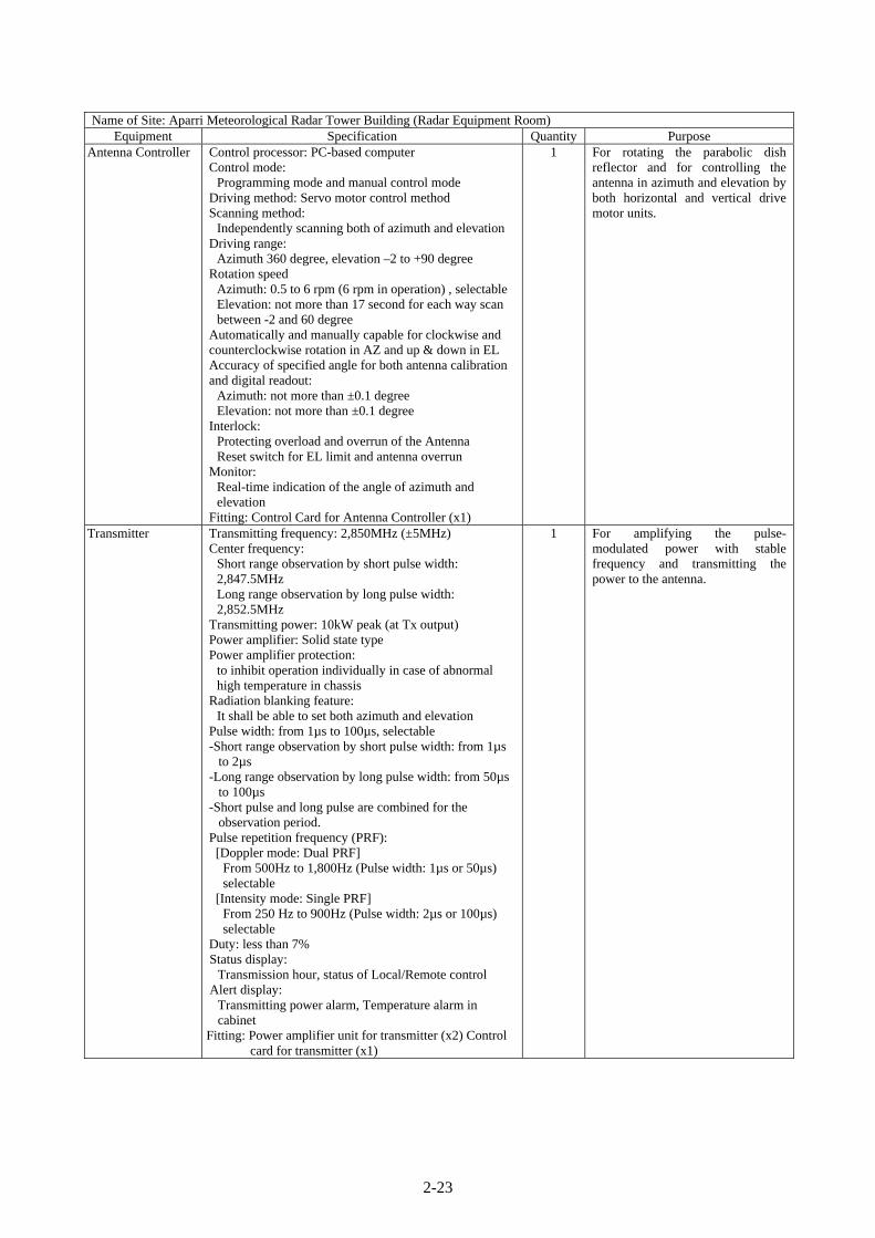
2-23
Name of Site: Aparri Meteorological Radar Tower Building (Radar Equipment Room) Equipment Specification Quantity Purpose
Antenna Controller Control processor: PC-based computer Control mode:
Programming mode and manual control mode Driving method: Servo motor control method Scanning method:
Independently scanning both of azimuth and elevation Driving range:
Azimuth 360 degree, elevation –2 to +90 degree Rotation speed
Azimuth: 0.5 to 6 rpm (6 rpm in operation) , selectable Elevation: not more than 17 second for each way scan between -2 and 60 degree
Automatically and manually capable for clockwise and counterclockwise rotation in AZ and up & down in EL Accuracy of specified angle for both antenna calibration and digital readout:
Azimuth: not more than ±0.1 degree Elevation: not more than ±0.1 degree
Interlock: Protecting overload and overrun of the Antenna Reset switch for EL limit and antenna overrun
Monitor: Real-time indication of the angle of azimuth and elevation
Fitting: Control Card for Antenna Controller (x1)
1 For rotating the parabolic dish reflector and for controlling the antenna in azimuth and elevation by both horizontal and vertical drive motor units.
Transmitter Transmitting frequency: 2,850MHz (±5MHz) Center frequency:
Short range observation by short pulse width: 2,847.5MHz Long range observation by long pulse width: 2,852.5MHz
Transmitting power: 10kW peak (at Tx output) Power amplifier: Solid state type Power amplifier protection:
to inhibit operation individually in case of abnormal high temperature in chassis
Radiation blanking feature: It shall be able to set both azimuth and elevation
Pulse width: from 1µs to 100µs, selectable -Short range observation by short pulse width: from 1µs
to 2µs -Long range observation by long pulse width: from 50µs
to 100µs -Short pulse and long pulse are combined for the
observation period. Pulse repetition frequency (PRF): [Doppler mode: Dual PRF]
From 500Hz to 1,800Hz (Pulse width: 1µs or 50µs) selectable
[Intensity mode: Single PRF] From 250 Hz to 900Hz (Pulse width: 2µs or 100µs) selectable
Duty: less than 7% Status display:
Transmission hour, status of Local/Remote control Alert display:
Transmitting power alarm, Temperature alarm in cabinet
Fitting: Power amplifier unit for transmitter (x2) Control card for transmitter (x1)
1 For amplifying the pulse- modulated power with stable frequency and transmitting the power to the antenna.

2-24
Digital Receiver and Signal Processor (DRSP)
Noise figure of the high frequency circuit: 3dB or better at the input terminal of low noise amplifier (LNA) Pulse compression type: Chirp modulation Pulse Compression ratio: 80 or less Receiver type: Coherent IF digitizer Sensitivity: -110dBm or better (at 10µs plus) Dynamic range: 80dB or better from noise level to the saturated level (depending on matched filter bandwidth) Doppler signal processor (including DSP card and Rx card): Software based controller Quantization: 14 bits Range bin: 1024 Processing area:
(Intensity mode) throughout 0 km to 440 km or more in range and 0 to 360 degree in azimuth (Doppler mode) throughout 0 km to 200 km or more in range and 0 to 360 degree in azimuth
Intensity signal process
-Ground clutter suppression: Frequency analysis by filter-bank and low frequency suppression with minimum influence to precipitation intensity -Logarithmic linearity: within ±1dB throughout 80dB -Range correction: depending on radar equation -Air-attenuation correction: 0.005dB/km in Observation Range
Velocity signal process -Processing type: Pulse Pair, FFT and Random Phase -Velocity De-arising: Real-time processing by Dual-PRF -Trigger control: PRF ratio selectable (2:3, 3:4, 4:5)
Averaging: Block averaging and/or sliding averaging Output data:
Reflectivity (Z), Doppler velocity (V), Spectrum width (W)
Output data resolution: 8bit Output data indicating interval:
within 1 minute after automatic scan Time adjustment:
Automatically adjustment by GPS NTP server (including GPS antenna)
Fitting: Control Card for DRSP (x1)
1 For receiving, pulse compression and processing echo signal from the Antenna. For suppressing unnecessary echo such as clutter signals reflected from the ground. For sending ingest data to radar TASK controller.
Dehydrator Capability of ventilation pressure: 3±1 liter/min, Upper limit: 300 ±30 hPa Lower limit: 70±30 hPa
1 For supplying dried and pressurized air into the wave-guide to reduce wave propagation loss.
Wave-guide Configuration
Wave-guide Type: S-band wave-guide
(conformity with WR-284 or equivalent) Circulator Allowable maximum power: at least 20 kW TR limitter (x6) Type: Dual backup type
1 For feeder line propagation wave traveling between the antenna and TX/RX.

2-25
Radar TASK Controller
CPU: Intel CoreTM2 Duo 2GHz or equivalent Main memory (RAM): 1024Mbytes or more Hard disk unit: 250GBytes or more x two (2) drives CD-RW Drive: one (1) Monitor display: Color LCD type, 19 inches or more LAN interface: IEEE802.3/u/ab, 10BASE-T/100BASE-TX/1000BASE-T, TCP/IP, two (2)ports or more LAN Arrester: for surge protection, RJ45 interface Input power: AC 220V, 60Hz, single phase Software Operating system: UNIX or LINUX-based
Application software: -Radar local control and monitoring -Observation scheduling -Radar echo display -Radar data generation and dissemination
1 For operating the radar system, monitoring condition of the radar system and generating raw product data. Control and monitoring items: Radiate control/status Azimuth/elevation position control/status TX standby status Pulse width control/status Antenna local/maintenance mode status.
Data & Protocol Converter
CPU: Intel CoreTM2 Duo 2GHz or equivalent Main memory (RAM): 1024Mbytes or more Hard disk unit: 250GBytes or more x two (2) drives CD-RW Drive: one (1) Monitor display: Color LCD type, 19 inches or more LAN interface: IEEE802.3/u/ab, 10BASE-T/100BASE-TX/1000BASE-T, TCP/IP, two (2)ports or more LAN Arrester: for surge protection, RJ45 interface Input power: AC 220V, 60Hz, single phase Software Operating system: UNIX or LINUX-based
Application software: -Data receiving, converting and transfer -Parameter setting -Display processing
1 For sending Raw data to central system according to specified interval.
Peripherals Compact UPS -Capacity: 500VA or more -Input power: AC 220V ±15%, single phase, 60Hz -Output power: AC 220V ±5%, single phase, 60Hz -Back-up time: 5 minutes or longer at full load
2 For supplying back-up AC power to computer equipment in order to enable proper shutdown procedure of the system in case of power failure.
Dual Switch -LAN interface: IEEE 802.3 Ethernet -Connection port: 100BASE-TX or more, eight (8)ports or more
-Input power: AC 220V, single phase, 60Hz -Each ports and power supply shall be duplicated
2 For connecting all the computing equipment on LAN.
Color Printer -Color inkjet type, A3 size -At least 1200 dpi resolution, 7ppm of faster printing
speed -Interface USB or LAN -Input power: AC 220V, single phase, 60Hz
1 For printing radar image.
Dual Optical Repeater -LAN interface: IEEE 802.3 Ethernet -Connection port: 100BASE-TX, one (1) port or more, Optical fiber interface one (1) set, Multi-mode (100Mbps)
-Input power: AC 220V, single phase, 60Hz -Each ports and power supply shall be duplicated
1 For converting electrical signal and optical signal on LAN for surge protection.
Radar Power Maintenance Panel -Circuit breaker: no-fuse-breaker type -Main breaker: no-fuse-breaker type or magnetic-breaker-Power distribution: 5 outputs include 1 spare -Input power: AC 220V, three phase, 60Hz -Output power: AC 220V, single phase, 60Hz
1 For distributing and supplying AC power to radar system.
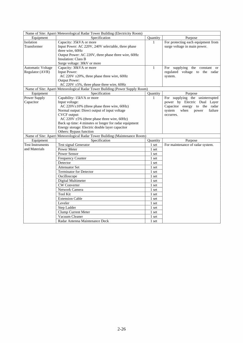
2-26
Name of Site: Aparri Meteorological Radar Tower Building (Electricity Room) Equipment Specification Quantity Purpose
Isolation Transformer
Capacity: 35kVA or more Input Power: AC 220V, 240V selectable, three phase three wire, 60Hz Output Power: AC 220V, three phase three wire, 60Hz Insulation: Class B Surge voltage: 30kV or more
1 For protecting each equipment from surge voltage in main power.
Automatic Voltage Regulator (AVR)
Capacity: 30kVA or more Input Power: AC 220V ±20%, three phase three wire, 60Hz
Output Power: AC 220V ±5%, three phase three wire, 60Hz
1 For supplying the constant or regulated voltage to the radar system.
Name of Site: Aparri Meteorological Radar Tower Building (Power Supply Room) Equipment Specification Quantity Purpose
Power Supply Capacitor
Capability: 15kVA or more Input voltage:
AC 220V±10% (three phase three wire, 60Hz) Normal output: Direct output of input voltage CVCF output:
AC 220V ±5% (three phase three wire, 60Hz) Back up time: 4 minutes or longer for radar equipment Energy storage: Electric double layer capacitor Others: Bypass function
1 For supplying the uninterrupted power by Electric Dual Layer Capacitor energy to the radar system when power failure occurres.
Name of Site: Aparri Meteorological Radar Tower Building (Maintenance Room) Equipment Specification Quantity Purpose
Test Instruments and Materials
Test signal Generator 1 set For maintenance of radar system. Power Meter 1 set Power Sensor 1 set Frequency Counter 1 set Detector 1 set Attenuator Set 1 set Terminator for Detector 1 set Oscilloscope 1 set Digital Multimeter 1 set CW Converter 1 set Network Camera 1 set Tool Kit 1 set Extension Cable 1 set Leveler 1 set Step Ladder 1 set Clump Current Meter 1 set Vacuum Cleaner 1 set Radar Antenna Maintenance Deck 1 set

2-27
Spare Parts Timing Belt for Antenna (For Azimuth Angle Signal) 1 set For maintenance of radar system. Timing Belt for Antenna (For Elevation Angle Signal) 1 set Encoder for Antenna (For Azimuth Angle Signal) 1 set Encoder for Antenna (For Elevation Angle Signal) 1 set
Motor for Antenna (For Azimuth Angle Signal) 1 set Motor for Antenna (For Elevation Angle Signal) 1 set Servo Unit for Antenna Controller (For Azimuth Angle Signal)
1 set
Servo Unit for Antenna Controller (For Elevation Angle Signal)
1 set
Power Supply Unit for Antenna Controller 1 set Power Supply Unit for Transmitter 1 set Power Supply Unit for Digital Receiver and Signal Processor
1 set
Fan Unit for Radar Equipment 2 set Hard Disk Unit for Computer (not less than 250GB) 1 set LAN Arrester 1 set Obstruction Light 2 pcs
Consumables Grease with Pump and Oil with Jug for Antenna 1 set For maintenance of radar system. Antenna Carbon Brush for Power 1 set Antenna Carbon Brush for Signal 1 set
Service Manuals Operation & Maintenance Hand Book 2 sets For maintenance of radar system.
Meteorological Radar System (Guiuan Meteorological Radar Observation Station)
Name of Site: Guiuan Meteorological Radar Tower Building (Radome Floor) Equipment Specification Quantity Purpose
Radome Type: Sandwich Type (Spherical surface) Dimension: Approx. 8m diameter Color: White Suitable non-observant and non-water stickling finish for making smooth surface Design Wind Pressure: 380kg/m2 Suitable Frequency: 2,850MHz (±5MHz) Transmission loss: 0.5dB or less on one way path in dry Relative humidity: 0 to 100% Lightning Rod: Protecting angles of 60degree Obstruction light: Waterproof lightning system Base ring including necessary installation materials
1 For protecting the radar antenna assembly (a parabolic dish reflector) and maintenance personnel from severe weather conditions and lightning attacks.
Antenna Type: Horn feed parabolic antenna Reflector: approx. 5m diameter Suitable Frequency: 2,850MHz (±5MHz) Beam width: not wider than 1.7 degree at -3dB point Antenna gain: 39dB or more without Radome Polarization: Linear, horizontal Side lobe level:
not more than -25dB without Radome Pedestal including the motor and rotary joint for azimuth and elevation
Driving range: Azimuth 360 degree, elevation -2 to +90 degree
Safety switch: to inhibit from radiating during maintenance works in Radome
VSWR: not more than 1.4 without Radome Optical connection box:
For converting electric control signal to optical one Directional coupler:
Coupling coefficiency: forward –50dB ±2dB backward –35dB ±1dB
Calibration accuracy: ±0.5dB VSWR: less than 1.10 Rating power: not less than 20kW
1 For radiating radar beam into the atmosphere and receiving scatter waves while rotating the parabola antenna as azimuth and elevation direction.

2-28
Name of Site: Guiuan Meteorological Radar Tower Building (Radar Equipment Room) Equipment Specification Quantity Purpose
Antenna Controller Control processor: PC-based computer Control mode:
Programming mode and manual control mode Driving method: Servo motor control method Scanning method:
Independently scanning both of azimuth and elevation Driving range:
Azimuth 360 degree, elevation –2 to +90 degree Rotation speed
Azimuth: 0.5 to 6 rpm (6 rpm in operation) , selectable Elevation: not more than 17 second for each way scan between -2 and 60 degree
Automatically and manually capable for clockwise and counterclockwise rotation in AZ and up & down in EL Accuracy of specified angle for both antenna calibration and digital readout:
Azimuth: not more than ±0.1 degree Elevation: not more than ±0.1 degree
Interlock: Protecting overload and overrun of the Antenna Reset switch for EL limit and antenna overrun
Monitor: Real-time indication of the angle of azimuth and elevation
Fitting: Control Card for Antenna Controller (x1)
1 For rotating the parabolic dish reflector and for controlling the antenna in azimuth and elevation by both horizontal and vertical drive motor units.
Transmitter Transmitting frequency: 2,850MHz (±5MHz) Center frequency:
Short range observation by short pulse width: 2,847.5MHz Long range observation by long pulse width: 2,852.5MHz
Transmitting power: 10kW peak (at Tx output) Power amplifier: Solid state type Power amplifier protection:
to inhibit operation individually in case of abnormal high temperature in chassis
Radiation blanking feature: It shall be able to set both azimuth and elevation
Pulse width: from 1µs to 100µs, selectable -Short range observation by short pulse width: from 1µs
to 2µs -Long range observation by long pulse width: from 50µs
to 100µs -Short pulse and long pulse are combined for the
observation period. Pulse repetition frequency (PRF): [Doppler mode: Dual PRF]
From 500Hz to 1,800Hz (Pulse width: 1µs or 50µs) selectable
[Intensity mode: Single PRF] From 250 Hz to 900Hz (Pulse width: 2µs or 100µs) selectable
Duty: less than 7% Status display:
Transmission hour, status of Local/Remote control Alert display:
Transmitting power alarm, Temperature alarm in cabinet
Fitting: Power amplifier unit for transmitter (x2) Control card for transmitter (x1)
1 For amplifying the pulse- modulated power with stable frequency and transmitting the power to the antenna.

2-29
Digital Receiver and Signal Processor (DRSP)
Noise figure of the high frequency circuit: 3dB or better at the input terminal of low noise amplifier (LNA) Pulse compression type: Chirp modulation Pulse Compression ratio: 80 or less Receiver type: Coherent IF digitizer Sensitivity: -110dBm or better (at 10µs plus) Dynamic range: 80dB or better from noise level to the saturated level (depending on matched filter bandwidth) Doppler signal processor (including DSP card and Rx card): Software based controller Quantization: 14 bits Range bin: 1024 Processing area:
(Intensity mode) throughout 0 km to 440 km or more in range and 0 to 360 degree in azimuth (Doppler mode) throughout 0 km to 200 km or more in range and 0 to 360 degree in azimuth
Intensity signal process
-Ground clutter suppression: Frequency analysis by filter-bank and low frequency suppression with minimum influence to precipitation intensity -Logarithmic linearity: within ±1dB throughout 80dB -Range correction: depending on radar equation -Air-attenuation correction: 0.005dB/km in Observation Range
Velocity signal process -Processing type: Pulse Pair, FFT and Random Phase -Velocity De-arising: Real-time processing by Dual-PRF -Trigger control: PRF ratio selectable (2:3, 3:4, 4:5)
Averaging: Block averaging and/or sliding averaging Output data:
Reflectivity (Z), Doppler velocity (V), Spectrum width (W)
Output data resolution: 8bit Output data indicating interval:
within 1 minute after automatic scan Time adjustment:
Automatically adjustment by GPS NTP server (including GPS antenna)
Fitting: Control Card for DRSP (x1)
1 For receiving, pulse compression and processing echo signal from the Antenna. For suppressing unnecessary echo such as clutter signals reflected from the ground. For sending ingest data to radar TASK controller.
Dehydrator Capability of ventilation pressure: 3±1 liter/min, Upper limit: 300 ±30 hPa Lower limit: 70±30 hPa
1 For supplying dried and pressurized air into the wave-guide to reduce wave propagation loss.
Wave-guide Configuration
Wave-guide Type: S-band wave-guide
(conformity with WR-284 or equivalent) Circulator Allowable maximum power: at least 20 kW TR limitter (x6) Type: Dual backup type
1 For feeder line propagation wave traveling between the antenna and TX/RX.
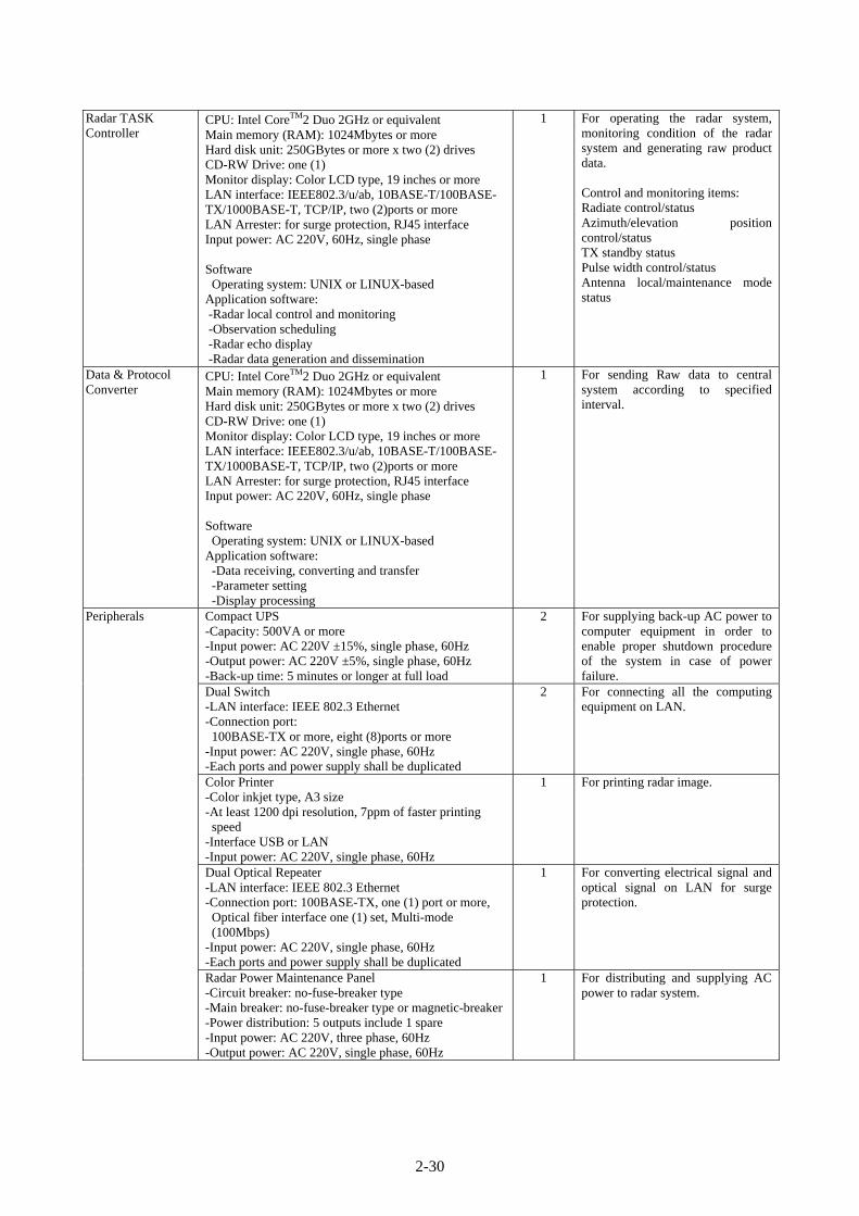
2-30
Radar TASK Controller
CPU: Intel CoreTM2 Duo 2GHz or equivalent Main memory (RAM): 1024Mbytes or more Hard disk unit: 250GBytes or more x two (2) drives CD-RW Drive: one (1) Monitor display: Color LCD type, 19 inches or more LAN interface: IEEE802.3/u/ab, 10BASE-T/100BASE-TX/1000BASE-T, TCP/IP, two (2)ports or more LAN Arrester: for surge protection, RJ45 interface Input power: AC 220V, 60Hz, single phase Software Operating system: UNIX or LINUX-based
Application software: -Radar local control and monitoring -Observation scheduling -Radar echo display -Radar data generation and dissemination
1 For operating the radar system, monitoring condition of the radar system and generating raw product data. Control and monitoring items: Radiate control/status Azimuth/elevation position control/status TX standby status Pulse width control/status Antenna local/maintenance mode status
Data & Protocol Converter
CPU: Intel CoreTM2 Duo 2GHz or equivalent Main memory (RAM): 1024Mbytes or more Hard disk unit: 250GBytes or more x two (2) drives CD-RW Drive: one (1) Monitor display: Color LCD type, 19 inches or more LAN interface: IEEE802.3/u/ab, 10BASE-T/100BASE-TX/1000BASE-T, TCP/IP, two (2)ports or more LAN Arrester: for surge protection, RJ45 interface Input power: AC 220V, 60Hz, single phase Software Operating system: UNIX or LINUX-based
Application software: -Data receiving, converting and transfer -Parameter setting -Display processing
1 For sending Raw data to central system according to specified interval.
Peripherals Compact UPS -Capacity: 500VA or more -Input power: AC 220V ±15%, single phase, 60Hz -Output power: AC 220V ±5%, single phase, 60Hz -Back-up time: 5 minutes or longer at full load
2 For supplying back-up AC power to computer equipment in order to enable proper shutdown procedure of the system in case of power failure.
Dual Switch -LAN interface: IEEE 802.3 Ethernet -Connection port: 100BASE-TX or more, eight (8)ports or more
-Input power: AC 220V, single phase, 60Hz -Each ports and power supply shall be duplicated
2 For connecting all the computing equipment on LAN.
Color Printer -Color inkjet type, A3 size -At least 1200 dpi resolution, 7ppm of faster printing
speed -Interface USB or LAN -Input power: AC 220V, single phase, 60Hz
1 For printing radar image.
Dual Optical Repeater -LAN interface: IEEE 802.3 Ethernet -Connection port: 100BASE-TX, one (1) port or more, Optical fiber interface one (1) set, Multi-mode (100Mbps)
-Input power: AC 220V, single phase, 60Hz -Each ports and power supply shall be duplicated
1 For converting electrical signal and optical signal on LAN for surge protection.
Radar Power Maintenance Panel -Circuit breaker: no-fuse-breaker type -Main breaker: no-fuse-breaker type or magnetic-breaker-Power distribution: 5 outputs include 1 spare -Input power: AC 220V, three phase, 60Hz -Output power: AC 220V, single phase, 60Hz
1 For distributing and supplying AC power to radar system.

2-31
Name of Site: Guiuan Meteorological Radar Tower Building (Electricity Room) Equipment Specification Quantity Purpose
Isolation Transformer
Capacity: 35kVA or more Input Power: AC 220V, 240V selectable, three phase three wire, 60Hz Output Power: AC 220V, three phase three wire, 60Hz Insulation: Class B Surge voltage: 30kV or more
1 For protecting each equipment from surge voltage in main power.
Automatic Voltage Regulator (AVR)
Capacity: 30kVA or more Input Power: AC 220V ±20%, three phase three wire, 60Hz
Output Power: AC 220V ±5%, three phase three wire, 60Hz
1 For supplying the constant or regulated voltage to the radar system.
Name of Site: Guiuan Meteorological Radar Tower Building (Power Supply Room) Equipment Specification Quantity Purpose
Power Supply Capacitor
Capability: 15kVA or more Input voltage:
AC 220V±10% (three phase three wire, 60Hz) Normal output: Direct output of input voltage CVCF output:
AC 220V ±5% (three phase three wire, 60Hz) Back up time: 4 minutes or longer for radar equipment Energy storage: Electric double layer capacitor Others: Bypass function
1 For supplying the uninterrupted power by Electric Dual Layer Capacitor energy to the radar system when power failure occurred.
Name of Site: Guiuan Meteorological Radar Tower Building (Maintenance Room) Equipment Specification Quantity Purpose
Test Instruments and Materials
Test signal Generator 1 set For maintenance of radar system. Power Meter 1 set Power Sensor 1 set Frequency Counter 1 set Detector 1 set Attenuator Set 1 set Terminator for Detector 1 set Oscilloscope 1 set Digital Multimeter 1 set CW Converter 1 set Network Camera 1 set Tool Kit 1 set Extension Cable 1 set Leveler 1 set Step Ladder 1 set Clump Current Meter 1 set Vacuum Cleaner 1 set Radar Antenna Maintenance Deck 1 set

2-32
Spare Parts
Timing Belt for Antenna (For Azimuth Angle Signal) 1 set For maintenance of radar system. Timing Belt for Antenna (For Elevation Angle Signal) 1 set Encoder for Antenna (For Azimuth Angle Signal) 1 set Encoder for Antenna (For Elevation Angle Signal) 1 set
Motor for Antenna (For Azimuth Angle Signal) 1 set Motor for Antenna (For Elevation Angle Signal) 1 set Servo Unit for Antenna Controller (For Azimuth Angle Signal)
1 set
Servo Unit for Antenna Controller (For Elevation Angle Signal)
1 set
Power Supply Unit for Antenna Controller 1 set Power Supply Unit for Transmitter 1 set Power Supply Unit for Digital Receiver and Signal Processor
1 set
Fan Unit for Radar Equipment 2 set Hard Disk Unit for Computer (not less than 250GB) 1 set LAN Arrester 1 set Obstruction Light 2 pcs
Consumables Grease with Pump and Oil with Jug for Antenna 1 set For maintenance of radar system. Antenna Carbon Brush for Power 1 set Antenna Carbon Brush for Signal 1 set
Service Manuals Operation & Maintenance Hand Book 2 sets For maintenance of radar system.

2-33
Meteorological Radar Data Display System (Virac Meteorological Radar Observation Station)
Name of Site: Virac Meteorological Radar Tower Building (Radar Equipment Room) Equipment Specification Quantity Purpose
Peripherals VoIP Gateway -Type: H323 or SIP -Decoding method: G.723, G.729 or G.711 -VoIP Interface: phone-line (Telephone, Fax, etc.) -VoIP port: 4ports -LAN interface: IEEE802.3/u, 10 BASE-T/100BASE-
TX, TCP/IP, one (1) port -Security: by the password -IP address: fixed type -Input power: AC 220V, single phase, 60Hz
1 For converting voice packet signal, and exchange dial signal for telephone.
Telephone -Type: Analog 2wire, DTMF
1 For voice communication.
Name of Site: Virac Meteorological Radar Tower Building (Observation Room) Equipment Specification Quantity Purpose
Severe Storm and Doppler Velocity Indicator
CPU: Intel CoreTM2 Duo 2GHz or equivalent Main memory (RAM): 1024Mbytes or more Hard disk unit: 250GBytes or more x two (2) drives CD-RW Drive: one (1) Monitor display: Color LCD type, 19 inches or more LAN interface: IEEE802.3/u/ab, 10BASE-T/100BASE-TX/1000BASE-T, TCP/IP, one (1) port or more LAN Arrester: for surge protection, RJ45 interface Input power: AC 220V, 60Hz, single phase Software Operation system: UNIX or LINUX-based
Application software: -Basic data monitoring feature -Weather product processing -Map projection -Product display & retrieval
1 For monitoring and alerting severe storm condition by various Doppler radar products.
Cyclone Tracking Monitor
CPU: Intel CoreTM2 Duo 2GHz or equivalent Main memory (RAM): 1024Mbytes or more Hard disk unit: 250GBytes or more x two (2) drives CD-RW Drive: one (1) Monitor display: Color LCD type, 19 inches or more LAN interface: IEEE802.3/u/ab, 10BASE-T/100BASE-TX/1000BASE-T, TCP/IP, one (1) port or more LAN Arrester: for surge protection, RJ45 interface Input power: AC 220V, 60Hz, single phase Software Operation system: UNIX or LINUX-based
Application software: -Radar local control and monitoring -Observation scheduling -Basic data monitoring feature -Weather product monitoring and display -Map projection -Product display & retrieval
1 For tracking cyclone course and predicting cyclone course and time.

2-34
Peripherals Color Printer -Color inkjet type, A3 size -At least 1200 dpi resolution, 7ppm or faster printing
speed -Interface USB or LAN -Input power: AC 220V, single phase, 60Hz
1 For printing radar image.
Dual Switch -LAN interface: IEEE 802.3 Ethernet -Connection port: 100BASE-TX or more, eight (8)ports or more
-Input power: AC 220V, single phase, 60Hz -Each ports and power supply shall be duplicated
1 For connecting all the computer equipment with LAN.
Dual Optical Repeater -LAN interface: IEEE 802.3 Ethernet -Connection port: 100BASE-TX or more, one (1) port or more Optical fiber interface one (1) set, Multi-mode (100Mbps)
-Input power: AC 220V, single phase, 60Hz -Each ports and power supply shall be duplicated
1 For converting electrical signal and optical signal on LAN for surge protection.
DVD Drive -Type: External Type -Interface: USB -Media: -R/+R/-RW/+RW -Input power: AC 220V, single phase, 60Hz
2 For storing of radar and weather information in DVD media.
Compact UPS -Capacity: 500VA or more -Input power: AC 220V ±15%, single phase, 60Hz -Output power: AC 220V ±5%, single phase, 60Hz -Back-up time: 5 minutes or longer at full load
4 For supplying back-up AC power to computer equipment in order to enable proper shutdown procedure of the system in case of power failure.
VoIP Gateway -Type: H323 or SIP -Decoding method: G.723, G.729 or G.711 -VoIP Interface: phone-line (Telephone, Fax, etc.) -VoIP port: 4ports -LAN interface: IEEE802.3/u, 10 BASE-T/100BASE-
TX, TCP/IP, one (1) port -Security: by the password -IP address: fixed type -Input power: AC 220V, single phase, 60Hz
1 For converting voice packet signal. Exchange dial signal for telephone.
Telephone -Type: Analog 2wire, DTMF
1 For voice communication.
Off-line Maintenance Computer -CPU: Intel CoreTM2 Duo 2GHz or equivalent -Main memory (RAM): 1024Mbytes or more -Hard disk unit: 250GBytes or more x two (2) drives -CD-RW Drive: one (1) -Monitor display: Color LCD type, 19 inches or more -LAN interface: IEEE802.3/u/ab, 10BASE-T/100BASE-TX/1000BASE-T, TCP/IP, one (1) port or more
-LAN Arrester: for surge protection, RJ45 interface -Input power: AC 220V, 60Hz, single phase -Software Operation System: Microsoft Windows XP or VISTA Application software: Microsoft Office 2007 or latest version
1 For weather service, record of daily operation and maintenance. In case of emergency, data communication to PAGASA Head Office by connecting GPRS/EDGE modem.
Color Printer (for Off-line Maintenance) -Color inkjet type, A4 size -At least 1200 dpi resolution, 7ppm or faster printing speed
-Interface USB -Input power: AC 220V, single phase, 60Hz
1 For Printing the record of daily operation and maintenance.

2-35
GPRS/EDGE Modem -GPRS class 10 or higher -EDGE class 6 or higher -Dual Band (900MHz, 1800MHz) -USB Interface -Input power: USB power supply -Driver software: For Windows
1 For Data Communication to PAGASA Head Office by connecting Off-line Maintenance Computer in case of emergency
Name of Site: Virac Meteorological Radar Tower Building (Data Analysis Room) Equipment Specification Quantity Purpose
Data Analyzing Unit
CPU: Intel CoreTM2 Duo 2GHz or equivalent Main memory (RAM): 1024Mbytes or more Hard disk unit: 250GBytes or more x two (2) drives CD-RW Drive: one (1) Monitor display: Color LCD type, 19 inches or more LAN interface: IEEE802.3/u/ab, 10BASE-T/100BASE-TX/1000BASE-T, TCP/IP, one (1) port or more LAN Arrester: for surge protection, RJ45 interface Input power: AC 220V, 60Hz, single phase Software Operation system: Unix or LINUX-based
Application software: -Basic data monitoring feature -Weather product processing -Map projection -Product display & retrieval
1 For analyzing weather phenomena by observed radar data.
Peripherals Color Printer -Color inkjet type, A3 size -At least 1200 dpi resolution, 7ppm or faster printing speed
-Interface USB or LAN -Input power: AC 220V, single phase, 60Hz
1 For printing radar image.
Compact UPS -Capacity: 500VA or more -Input power: AC 220V ±15%, single phase, 60Hz -Output power: AC 220V ±5%, single phase, 60Hz -Back-up time: 5 minutes or longer at full load
1 For supplying back-up AC power to computer equipment in order to enable proper shutdown procedure of the system in case of power failure.
VoIP Gateway -Type: H323 or SIP -Decoding method: G.723, G.729 or G.711 -VoIP Interface: phone-line (Telephone, Fax, etc.) -VoIP port: 4ports -LAN interface: IEEE802.3/u, 10 BASE-T/100BASE-
TX, TCP/IP, one (1) port -Security: by the password -IP address: fixed type -Input power: AC 220V, single phase, 60Hz
1 For converting voice packet signal. Exchange dial signal for telephone.
Telephone -Type: Analog 2wire, DTMF
1 For voice communication.
Spare Parts Hard Disk Unit for Computer (not less than 250GB) 1 set For maintenance of the system. LAN Arrester 1 set
Service Manuals Operation & Maintenance Hand Book 1 set For maintenance of the system.

2-36
Meteorological Radar Data Display System (Aparri Meteorological Radar Observation Station)
Name of Site: Aparri Meteorological Radar Tower Building (Radar Equipment Room) Equipment Specification Quantity Purpose
Peripherals VoIP Gateway -Type: H323 or SIP -Decoding method: G.723, G.729 or G.711 -VoIP Interface: phone-line (Telephone, Fax, etc.) -VoIP port: 4ports -LAN interface: IEEE802.3/u, 10 BASE-T/100BASE-
TX, TCP/IP, one (1) port -Security: by the password -IP address: fixed type -Input power: AC 220V, single phase, 60Hz
1 For converting voice packet signal, and exchange dial signal for telephone.
Telephone -Type: Analog 2wire, DTMF
1 For voice communication.
Name of Site: Aparri Meteorological Radar Tower Building (Observation Room) Equipment Specification Quantity Purpose
Severe Storm and Doppler Velocity Indicator
CPU: Intel CoreTM2 Duo 2GHz or equivalent Main memory (RAM): 1024Mbytes or more Hard disk unit: 250GBytes or more x two (2) drives CD-RW Drive: one (1) Monitor display: Color LCD type, 19 inches or more LAN interface: IEEE802.3/u/ab, 10BASE-T/100BASE-TX/1000BASE-T, TCP/IP, one (1) port or more LAN Arrester: for surge protection, RJ45 interface Input power: AC 220V, 60Hz, single phase Software Operation system: UNIX or LINUX-based
Application software: -Basic data monitoring feature -Weather product processing -Map projection -Product display & retrieval
1 For monitoring and alerting severe storm condition by various Doppler radar products.
Cyclone Tracking Monitor
CPU: Intel CoreTM2 Duo 2GHz or equivalent Main memory (RAM): 1024Mbytes or more Hard disk unit: 250GBytes or more x two (2) drives CD-RW Drive: one (1) Monitor display: Color LCD type, 19 inches or more LAN interface: IEEE802.3/u/ab, 10BASE-T/100BASE-TX/1000BASE-T, TCP/IP, one (1) port or more LAN Arrester: for surge protection, RJ45 interface Input power: AC 220V, 60Hz, single phase Software Operation system: UNIX or LINUX-based
Application software: -Radar local control and monitoring -Observation scheduling -Basic data monitoring feature -Weather product monitoring and display -Map projection -Product display & retrieval
1 For tracking cyclone course and predicting cyclone course and time.

2-37
Peripherals Color Printer -Color inkjet type, A3 size -At least 1200 dpi resolution, 7ppm or faster printing
speed -Interface USB or LAN -Input power: AC 220V, single phase, 60Hz
1 For printing radar image.
Dual Switch -LAN interface: IEEE 802.3 Ethernet -Connection port: 100BASE-TX or more, eight (8)ports or more
-Input power: AC 220V, single phase, 60Hz -Each ports and power supply shall be duplicated
1 For connecting all the computer equipment with LAN.
Dual Optical Repeater -LAN interface: IEEE 802.3 Ethernet -Connection port: 100BASE-TX or more, one (1) port or more Optical fiber interface one (1) set, Multi-mode (100Mbps)
-Input power: AC 220V, single phase, 60Hz -Each ports and power supply shall be duplicated
1 For converting electrical signal and optical signal on LAN for surge protection.
DVD Drive -Type: External Type -Interface: USB -Media: -R/+R/-RW/+RW -Input power: AC 220V, single phase, 60Hz
2 For storing of radar and weather information in DVD media.
Compact UPS -Capacity: 500VA or more -Input power: AC 220V ±15%, single phase, 60Hz -Output power: AC 220V ±5%, single phase, 60Hz -Back-up time: 5 minutes or longer at full load
4 For supplying back-up AC power to computer equipment in order to enable proper shutdown procedure of the system in case of power failure.
VoIP Gateway -Type: H323 or SIP -Decoding method: G.723, G.729 or G.711 -VoIP Interface: phone-line (Telephone, Fax, etc.) -VoIP port: 4ports -LAN interface: IEEE802.3/u, 10 BASE-T/100BASE-
TX, TCP/IP, one (1) port -Security: by the password -IP address: fixed type -Input power: AC 220V, single phase, 60Hz
1 For converting voice packet signal. Exchange dial signal for telephone.
Telephone -Type: Analog 2wire, DTMF
1 For voice communication.
Off-line Maintenance Computer -CPU: Intel CoreTM2 Duo 2GHz or equivalent -Main memory (RAM): 1024Mbytes or more -Hard disk unit: 250GBytes or more x two (2) drives -CD-RW Drive: one (1) -Monitor display: Color LCD type, 19 inches or more -LAN interface: IEEE802.3/u/ab, 10BASE-T/100BASE-TX/1000BASE-T, TCP/IP, one (1) port or more
-LAN Arrester: for surge protection, RJ45 interface -Input power: AC 220V, 60Hz, single phase -Software Operation System: Microsoft Windows XP or VISTA Application software: Microsoft Office 2007 or latest version
1 For weather service, record of daily operation and maintenance. In case of emergency, data communication to PAGASA Head Office by connecting GPRS/EDGE modem
Color Printer (for Off-line Maintenance) -Color inkjet type, A4 size -At least 1200 dpi resolution, 7ppm or faster printing speed
-Interface USB -Input power: AC 220V, single phase, 60Hz
1 For Printing the record of daily operation and maintenance.

2-38
GPRS/EDGE Modem -GPRS class 10 or higher -EDGE class 6 or higher -Dual Band (900MHz, 1800MHz) -USB Interface -Input power: USB power supply -Driver software: For Windows
1 For Data Communication to PAGASA Head Office by connecting Off-line Maintenance Computer in case of emergency.
Name of Site: Aparri Meteorological Radar Tower Building (Data Analysis Room) Equipment Specification Quantity Purpose
Data Analyzing Unit
CPU: Intel CoreTM2 Duo 2GHz or equivalent Main memory (RAM): 1024Mbytes or more Hard disk unit: 250GBytes or more x two (2) drives CD-RW Drive: one (1) Monitor display: Color LCD type, 19 inches or more LAN interface: IEEE802.3/u/ab, 10BASE-T/100BASE-TX/1000BASE-T, TCP/IP, one (1) port or more LAN Arrester: for surge protection, RJ45 interface Input power: AC 220V, 60Hz, single phase Software Operation system: Unix or LINUX-based
Application software: -Basic data monitoring feature -Weather product processing -Map projection -Product display & retrieval
1 For analyzing weather phenomena by observed radar data.
Peripherals Color Printer -Color inkjet type, A3 size -At least 1200 dpi resolution, 7ppm or faster printing speed
-Interface USB or LAN -Input power: AC 220V, single phase, 60Hz
1 For printing radar image.
Compact UPS -Capacity: 500VA or more -Input power: AC 220V ±15%, single phase, 60Hz -Output power: AC 220V ±5%, single phase, 60Hz -Back-up time: 5 minutes or longer at full load
1 For supplying back-up AC power to computer equipment in order to enable proper shutdown procedure of the system in case of power failure.
VoIP Gateway -Type: H323 or SIP -Decoding method: G.723, G.729 or G.711 -VoIP Interface: phone-line (Telephone, Fax, etc.) -VoIP port: 4ports -LAN interface: IEEE802.3/u, 10 BASE-T/100BASE-
TX, TCP/IP, one (1) port -Security: by the password -IP address: fixed type -Input power: AC 220V, single phase, 60Hz
1 For converting voice packet signal. Exchange dial signal for telephone.
Telephone -Type: Analog 2wire, DTMF
1 For voice communication.
Spare Parts Hard Disk Unit for Computer (not less than 250GB) 1 set For maintenance of the system. LAN Arrester 1 set
Service Manuals Operation & Maintenance Hand Book 1 set For maintenance of the system.

2-39
Meteorological Radar Data Display System (Guiuan Meteorological Radar Observation Station)
Name of Site: Guiuan Meteorological Radar Tower Building (Radar Equipment Room) Equipment Specification Quantity Purpose
Peripherals VoIP Gateway -Type: H323 or SIP -Decoding method: G.723, G.729 or G.711 -VoIP Interface: phone-line (Telephone, Fax, etc.) -VoIP port: 4ports -LAN interface: IEEE802.3/u, 10 BASE-T/100BASE-
TX, TCP/IP, one (1) port -Security: by the password -IP address: fixed type -Input power: AC 220V, single phase, 60Hz
1 For converting voice packet signal, and exchange dial signal for telephone.
Telephone -Type: Analog 2wire, DTMF
1 For voice communication.
Name of Site: Guiuan Meteorological Radar Tower Building (Observation Room) Equipment Specification Quantity Purpose
Severe Storm and Doppler Velocity Indicator
CPU: Intel CoreTM2 Duo 2GHz or equivalent Main memory (RAM): 1024Mbytes or more Hard disk unit: 250GBytes or more x two (2) drives CD-RW Drive: one (1) Monitor display: Color LCD type, 19 inches or more LAN interface: IEEE802.3/u/ab, 10BASE-T/100BASE-TX/1000BASE-T, TCP/IP, one (1) port or more LAN Arrester: for surge protection, RJ45 interface Input power: AC 220V, 60Hz, single phase Software Operation system: UNIX or LINUX-based
Application software: -Basic data monitoring feature -Weather product processing -Map projection -Product display & retrieval
1 For monitoring and alerting severe storm condition by various Doppler radar products.
Cyclone Tracking Monitor
CPU: Intel CoreTM2 Duo 2GHz or equivalent Main memory (RAM): 1024Mbytes or more Hard disk unit: 250GBytes or more x two (2) drives CD-RW Drive: one (1) Monitor display: Color LCD type, 19 inches or more LAN interface: IEEE802.3/u/ab, 10BASE-T/100BASE-TX/1000BASE-T, TCP/IP, one (1) port or more LAN Arrester: for surge protection, RJ45 interface Input power: AC 220V, 60Hz, single phase Software Operation system: UNIX or LINUX-based
Application software: -Radar local control and monitoring -Observation scheduling -Basic data monitoring feature -Weather product monitoring and display -Map projection -Product display & retrieval
1 For tracking cyclone course and predicting cyclone course and time.

2-40
Peripherals Color Printer -Color inkjet type, A3 size -At least 1200 dpi resolution, 7ppm or faster printing
speed -Interface USB or LAN -Input power: AC 220V, single phase, 60Hz
1 For printing radar image.
Dual Switch -LAN interface: IEEE 802.3 Ethernet -Connection port: 100BASE-TX or more, eight (8)ports or more
-Input power: AC 220V, single phase, 60Hz -Each ports and power supply shall be duplicated
1 For connecting all the computing equipment with LAN.
Dual Optical Repeater -LAN interface: IEEE 802.3 Ethernet -Connection port: 100BASE-TX or more, one (1) port or more Optical fiber interface one (1) set, Multi-mode (100Mbps)
-Input power: AC 220V, single phase, 60Hz -Each ports and power supply shall be duplicated
1 For converting electrical signal and optical signal on LAN for surge protection.
DVD Drive -Type: External Type -Interface: USB -Media: -R/+R/-RW/+RW -Input power: AC 220V, single phase, 60Hz
2 For storing of radar and weather information in DVD media.
Compact UPS -Capacity: 500VA or more -Input power: AC 220V ±15%, single phase, 60Hz -Output power: AC 220V ±5%, single phase, 60Hz -Back-up time: 5 minutes or longer at full load
4 For supplying back-up AC power to computer equipment in order to enable proper shutdown procedure of the system in case of power failure.
VoIP Gateway -Type: H323 or SIP -Decoding method: G.723, G.729 or G.711 -VoIP Interface: phone-line (Telephone, Fax, etc.) -VoIP port: 4ports -LAN interface: IEEE802.3/u, 10 BASE-T/100BASE-
TX, TCP/IP, one (1) port -Security: by the password -IP address: fixed type -Input power: AC 220V, single phase, 60Hz
1 For converting voice packet signal. Exchange dial signal for telephone.
Telephone -Type: Analog 2wire, DTMF
1 For voice communication.
Off-line Maintenance Computer -CPU: Intel CoreTM2 Duo 2GHz or equivalent -Main memory (RAM): 1024Mbytes or more -Hard disk unit: 250GBytes or more x two (2) drives -CD-RW Drive: one (1) -Monitor display: Color LCD type, 19 inches or more -LAN interface: IEEE802.3/u/ab, 10BASE-T/100BASE-TX/1000BASE-T, TCP/IP, one (1) port or more
-LAN Arrester: for surge protection, RJ45 interface -Input power: AC 220V, 60Hz, single phase -Software Operation System: Microsoft Windows XP or VISTA Application software: Microsoft Office 2007 or latest version
1 For weather service, record of daily operation and maintenance. In case of emergency, data communication to PAGASA Head Office by connecting GPRS/EDGE modem.
Color Printer (for Off-line Maintenance) -Color inkjet type, A4 size -At least 1200 dpi resolution, 7ppm or faster printing speed
-Interface USB -Input power: AC 220V, single phase, 60Hz
1 For Printing the record of daily operation and maintenance
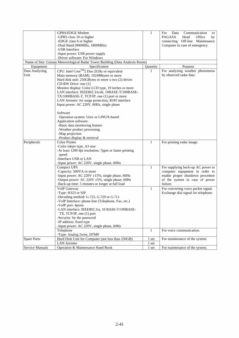
2-41
GPRS/EDGE Modem -GPRS class 10 or higher -EDGE class 6 or higher -Dual Band (900MHz, 1800MHz) -USB Interface -Input power: USB power supply -Driver software: For Windows
1 For Data Communication to PAGASA Head Office by connecting Off-line Maintenance Computer in case of emergency
Name of Site: Guiuan Meteorological Radar Tower Building (Data Analysis Room) Equipment Specification Quantity Purpose
Data Analyzing Unit
CPU: Intel CoreTM2 Duo 2GHz or equivalent Main memory (RAM): 1024Mbytes or more Hard disk unit: 250GBytes or more x two (2) drives CD-RW Drive: one (1) Monitor display: Color LCD type, 19 inches or more LAN interface: IEEE802.3/u/ab, 10BASE-T/100BASE-TX/1000BASE-T, TCP/IP, one (1) port or more LAN Arrester: for surge protection, RJ45 interface Input power: AC 220V, 60Hz, single phase Software Operation system: Unix or LINUX-based
Application software: -Basic data monitoring feature -Weather product processing -Map projection -Product display & retrieval
1 For analyzing weather phenomena by observed radar data.
Peripherals Color Printer -Color inkjet type, A3 size -At least 1200 dpi resolution, 7ppm or faster printing speed
-Interface USB or LAN -Input power: AC 220V, single phase, 60Hz
1 For printing radar image.
Compact UPS -Capacity: 500VA or more -Input power: AC 220V ±15%, single phase, 60Hz -Output power: AC 220V ±5%, single phase, 60Hz -Back-up time: 5 minutes or longer at full load
1 For supplying back-up AC power to computer equipment in order to enable proper shutdown procedure of the system in case of power failure.
VoIP Gateway -Type: H323 or SIP -Decoding method: G.723, G.729 or G.711 -VoIP Interface: phone-line (Telephone, Fax, etc.) -VoIP port: 4ports -LAN interface: IEEE802.3/u, 10 BASE-T/100BASE-
TX, TCP/IP, one (1) port -Security: by the password -IP address: fixed type -Input power: AC 220V, single phase, 60Hz
1 For converting voice packet signal. Exchange dial signal for telephone.
Telephone -Type: Analog 2wire, DTMF
1 For voice communication.
Spare Parts Hard Disk Unit for Computer (not less than 250GB) 1 set For maintenance of the system. LAN Arrester 1 set
Service Manuals Operation & Maintenance Hand Book 1 set For maintenance of the system.

2-42
Meteorological Radar Data Display System (PAGASA Head Office, Weather and Flood Forecasting Center)
Name of Site: PAGASA Head Office, Weather and Flood Forecasting Center Equipment Specification Quantity Purpose
Composite Processor
CPU: Intel CoreTM2 Duo 2GHz or equivalent Main memory (RAM): 1024Mbytes or more Hard disk unit: 250GBytes or more x two (2) drives CD-RW Drive: one (1) Monitor display: Color LCD type, 42 inches or more, include support stand set LAN interface: IEEE802.3/u/ab, 10BASE-T/100BASE-TX/1000BASE-T, TCP/IP, one (1) port or more LAN Arrester: for surge protection, RJ45 interface Input power: AC 220V, 60Hz, single phase Software Operation system: UNIX or LINUX-based
Application software -Data Receiving -Data Dissemination -Display of radar echo -Display of status -Parameter setting for composite -Output of radar image file
1 For generation composite picture from incoming data of all the radar stations.
Meteorological Data Archiving Unit
CPU: Intel CoreTM2 Duo 2GHz or equivalent Main memory (RAM): 1024Mbytes or more Hard disk unit: 250GBytes or more x two (2) drives CD-RW Drive: one (1) Monitor display: Color LCD type, 19 inches or more LAN interface: IEEE802.3/u/ab, 10BASE-T/100BASE-TX/1000BASE-T, TCP/IP, one (1) port or more LAN Arrester: for surge protection, RJ45 interface Input power: AC 220V, 60Hz, single phase Software
Operation system: Unix or LINUX-based Application software:
-Data Receiving -Display feature -Storing to external storages
1 For storing of radar and weather information to selected media.
Product Retrieval Unit
CPU: Intel CoreTM2 Duo 2GHz or equivalent Main memory (RAM): 1024Mbytes or more Hard disk unit: 250GBytes or more x two (2) drives CD-RW Drive: one (1) Monitor display: Color LCD type, 19 inches or more LAN interface: IEEE802.3/u/ab, 10BASE-T/100BASE-TX/1000BASE-T, TCP/IP, one (1) port or more LAN Arrester: for surge protection, RJ45 interface Input power: AC 220V, 60Hz, single phase Software
Operation system: Unix or LINUX-based Application software:
-Data Receiving -Basic data monitoring feature -Various weather products retrieving -Map projection -Product display & retrieval
1 For retrieving and displaying of radar data.

2-43
Accumulated Rainfall Processor
CPU: Intel CoreTM2 Duo 2GHz or equivalent Main memory (RAM): 1024Mbytes or more Hard disk unit: 250GBytes or more x two (2) drives CD-RW Drive: one (1) Monitor display: Color LCD type, 19 inches or more LAN interface: IEEE802.3/u/ab, 10BASE-T/100BASE-TX/1000BASE-T, TCP/IP, one (1) port or more LAN Arrester: for surge protection, RJ45 interface Input power: AC 220V, 60Hz, single phase Software
Operation system: UNIX or LINUX-based Application software
-Data Receiving -Data Dissemination -Display of radar echo -Display of status -Parameter setting and calculating
1 For generating and sending accumulated rainfall data.
Doppler Velocity Indicator
CPU: Intel CoreTM2 Duo 2GHz or equivalent Main memory (RAM): 1024Mbytes or more Hard disk unit: 250GBytes or more x two (2) drives CD-RW Drive: one (1) Monitor display: Color LCD type, 19 inches or more LAN interface: IEEE802.3/u/ab, 10BASE-T/100BASE-TX/1000BASE-T, TCP/IP, one (1) port or more LAN Arrester: for surge protection, RJ45 interface Input power: AC 220V, 60Hz, single phase Software
Operation system: UNIX or LINUX-based Application software
-Data Receiving -Doppler Product Processing -Map projection -Product display & retrieval
1 For generating various wind profile with each mesh by Doppler data.
Cyclone Tracking Monitor
CPU: Intel CoreTM2 Duo 2GHz or equivalent Main memory (RAM): 1024Mbytes or more Hard disk unit: 250GBytes or more x two (2) drives CD-RW Drive: one (1) Monitor display: Color LCD type, 19 inches or more LAN interface: IEEE802.3/u/ab, 10BASE-T/100BASE-TX/1000BASE-T, TCP/IP, one (1) port or more LAN Arrester: for surge protection, RJ45 interface Input power: AC 220V, 60Hz, single phase Software
Operation system: UNIX or LINUX-based Application software
-Basic data monitoring feature -Weather product monitoring and display -Map projection -Product display & retrieval
1 For tracking cyclone course and predicting cyclone course and time.

2-44
Radar Web Server CPU: Intel CoreTM2 Duo 2GHz or equivalent Main memory (RAM): 1024Mbytes or more Hard disk unit: 250GBytes or more x two (2) drives CD-RW Drive: one (1) Monitor display: Color LCD type, 19 inches or more LAN interface: IEEE802.3/u/ab, 10BASE-T/100BASE-TX/1000BASE-T, TCP/IP, two (2) ports or more LAN Arrester: for surge protection, RJ45 interface Input power: AC 220V, 60Hz, single phase Software
Operation system: UNIX or LINUX-based Application software
-Data Receiving -Product output to Web -Radar image output
1 For output of various product with web based image.
Peripherals Color Printer -Color inkjet type, A3 size -At least 1200 dpi resolution, 7ppm or faster printing speed
-Interface USB or LAN -Input power: AC 220V, single phase, 60Hz
2 For printing radar image.
Dual Router -LAN interface: IEEE 802.3 Ethernet -Connection port: 100BASE-TX, two (2)ports or more -Routing: IP routing -Input power: AC 220V, single phase, 60Hz -Each ports and power supply shall be duplicated
1 For connecting and routing the Radar Web Server to the PAGASA Internet Server.
Dual Switch -LAN interface: IEEE 802.3 Ethernet -Connection port: 100BASE-TX, twenty four (24)ports or more -Input power: AC 220V, single phase, 60Hz -Each ports and power supply shall be duplicated
1 For connecting all the computer equipment on LAN.
DVD Drive -Type: External Type -Interface: USB -Media: -R/+R/-RW/+RW -Input power: AC 220V, single phase, 60Hz
2 For storing of radar and weather information in DVD media.
DDS Drive -Type: External Type -Interface: USB -Media: DDS4 -Input power: AC 220V, single phase, 60Hz
2 For storing of radar and weather information to DDS media.
VoIP Gateway -Type: H323 or SIP -Decoding method: G.723, G.729 or G.711 -VoIP Interface: phone-line (Telephone, Fax, etc.) -VoIP port: 4ports -LAN interface: IEEE802.3/u, 10 BASE-T/100BASE-TX,
TCP/IP, one (1) port -Security: by the password -IP address: fixed type -Input power: AC 220V, single phase, 60Hz
1 For converting voice packet signal, and exchange dial signal for telephone.
Telephone -Type: Analog 2wire, DTMF
1 For voice communication.
Compact UPS -Capacity: 500VA or more -Input power: AC 220V ±15%, single phase, 60Hz -Output power: AC 220V ±5%, single phase, 60Hz -Back-up time: 5 minutes or longer at full load
8 For supplying back-up AC power to computing equipment in order to enable proper shutdown procedure of the system in case of power failure.
Automatic Voltage Regulator (AVR) -Capacity: 1kVA or more -Input power: AC 220V ±20%, single phase, 60Hz -Output power: AC 220V ±5%, single phase, 60Hz
8 For supplying the constant or regulated voltage to the computer system.

2-45
Off-line Maintenance Computer -CPU: Intel CoreTM2 Duo 2GHz or equivalent -Main memory (RAM): 1024Mbytes or more -Hard disk unit: 250GBytes or more x two (2) drives -CD-RW Drive: one (1) -Monitor display: Color LCD type, 19 inches or more -LAN interface: IEEE802.3/u/ab, 10BASE-T/ 100BASE-TX/1000BASE-T, TCP/IP, one (1) ports or more
-LAN Arrester: for surge protection, RJ45 interface -Input power: AC 220V, 60Hz, single phase -Software Operation System: Microsoft Windows XP or VISTA Application software: Microsoft Office Version 2007 (Latest Version)
1 For weather service, record of daily operation and maintenance In case of emergency, data communication to PAGASA Head Office by connecting GPRS/EDGE modem
Color Printer (for Off-line Maintenance) -Color inkjet type, A4 size -At least 1200 dpi resolution, 7ppm of faster printing speed
-Interface: USB -Input power: AC 220V, single phase, 60Hz
1 For Printing the record of daily operation and maintenance
GPRS/EDGE Modem -GPRS class 10 or higher -EDGE class 6 or higher -Dual Band (900MHz, 1800MHz) -USB Interface -Input power: USB power supply -Driver software: For Windows
1 For Data Communication to PAGASA Head Office by connecting Off-line Maintenance Computer in case of emergency
Spare Parts Hard Disk Unit for Computer (not less than 250GB) 4 sets For maintenance of the system. LAN Arrester 4 sets
Service Manuals Operation & Maintenance Hand Book 1 set For maintenance of the system.
Meteorological Data Satellite Communication System (VSAT) (Virac Meteorological Radar Observation Station)
Name of Site: Virac Meteorological Radar Tower Building Equipment Specification Quantity Purpose
VSAT Out-door Unit (ODU/Transmitter)
Frequency band: C band Output Frequency Range: 5.850GHz~6.425GHz Input Frequency Range: 950MHz~1525MHz Output Power Level: +40dBm min Linear Gain: 64dB nominal Gain Stability: 5dBp-p max IM3: -26dBc max External Reference Frequency: 10MHz(sin-wave) Input Power: -5 to +5 dBm Local Phase Noise : -60 dBc / Hz @100Hz : -70 dBc / Hz @1kHz : -80 dBc / Hz @10kHz : -90 dBc / Hz @100kHz Spurious In-band: -50dBc max
Out-of-band: -50dBc max Receive band: -70dBm max
Input Impedance: 50 ohms Input V.S.W.R.: 2:1 max Output V.S.W.R.: 2:1 max Input DC power: +48 V DC(+38 to +60 V DC) Input Interface IF/10MHz: N-female (50 ohms) DC Power: MS connector-female Output Interface: Waveguide,CPR137-G
1
Transmitter for communicating meteorological service and radar data transmission via satellite.
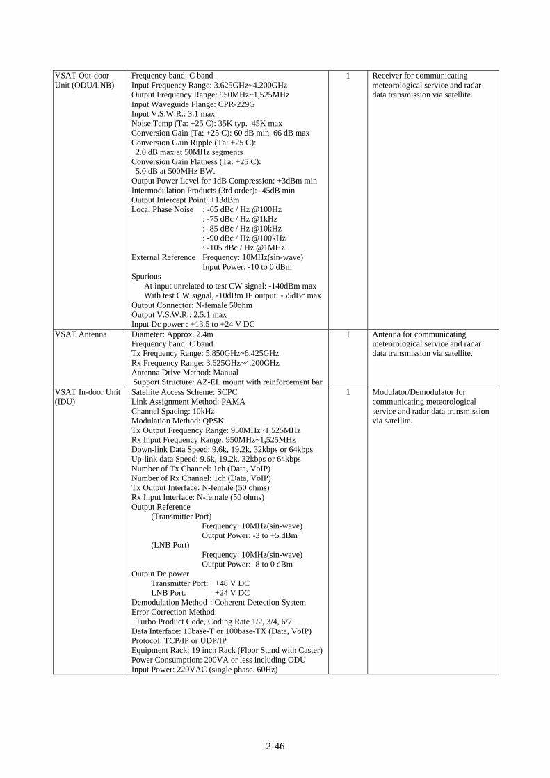
2-46
VSAT Out-door Unit (ODU/LNB)
Frequency band: C band Input Frequency Range: 3.625GHz~4.200GHz Output Frequency Range: 950MHz~1,525MHz Input Waveguide Flange: CPR-229G Input V.S.W.R.: 3:1 max Noise Temp (Ta: +25 C): 35K typ. 45K max Conversion Gain (Ta: +25 C): 60 dB min. 66 dB max Conversion Gain Ripple (Ta: +25 C): 2.0 dB max at 50MHz segments
Conversion Gain Flatness (Ta: +25 C): 5.0 dB at 500MHz BW.
Output Power Level for 1dB Compression: +3dBm min Intermodulation Products (3rd order): -45dB min Output Intercept Point: +13dBm Local Phase Noise : -65 dBc / Hz @100Hz : -75 dBc / Hz @1kHz : -85 dBc / Hz @10kHz : -90 dBc / Hz @100kHz : -105 dBc / Hz @1MHz
External Reference Frequency: 10MHz(sin-wave) Input Power: -10 to 0 dBm Spurious
At input unrelated to test CW signal: -140dBm max With test CW signal, -10dBm IF output: -55dBc max
Output Connector: N-female 50ohm Output V.S.W.R.: 2.5:1 max Input Dc power : +13.5 to +24 V DC
1 Receiver for communicating meteorological service and radar data transmission via satellite.
VSAT Antenna Diameter: Approx. 2.4m Frequency band: C band Tx Frequency Range: 5.850GHz~6.425GHz Rx Frequency Range: 3.625GHz~4.200GHz Antenna Drive Method: Manual Support Structure: AZ-EL mount with reinforcement bar
1 Antenna for communicating meteorological service and radar data transmission via satellite.
VSAT In-door Unit (IDU)
Satellite Access Scheme: SCPC Link Assignment Method: PAMA Channel Spacing: 10kHz Modulation Method: QPSK Tx Output Frequency Range: 950MHz~1,525MHz Rx Input Frequency Range: 950MHz~1,525MHz Down-link Data Speed: 9.6k, 19.2k, 32kbps or 64kbps Up-link data Speed: 9.6k, 19.2k, 32kbps or 64kbps Number of Tx Channel: 1ch (Data, VoIP) Number of Rx Channel: 1ch (Data, VoIP) Tx Output Interface: N-female (50 ohms) Rx Input Interface: N-female (50 ohms) Output Reference
(Transmitter Port) Frequency: 10MHz(sin-wave)
Output Power: -3 to +5 dBm (LNB Port)
Frequency: 10MHz(sin-wave) Output Power: -8 to 0 dBm
Output Dc power Transmitter Port: +48 V DC LNB Port: +24 V DC
Demodulation Method : Coherent Detection System Error Correction Method: Turbo Product Code, Coding Rate 1/2, 3/4, 6/7
Data Interface: 10base-T or 100base-TX (Data, VoIP) Protocol: TCP/IP or UDP/IP Equipment Rack: 19 inch Rack (Floor Stand with Caster)Power Consumption: 200VA or less including ODU Input Power: 220VAC (single phase. 60Hz)
1 Modulator/Demodulator for communicating meteorological service and radar data transmission via satellite.

2-47
Arrester Box For 48V DC Power: 1ch Striking Voltage: 88Vmin Response Time: 0.1 μs Max. Surge current capacity: 2000A (8/20μs)
For Thermal sensor: 1ch Striking Voltage: ±6Vmin Response Time: 0.1 μs Max. Surge current capacity: 5000A (8/20μs)
For high frequency signal: 2ch Striking Voltage: 90Vmin Frequency: DC-2.2GHz Max. Surge current capacity: 20KA (8/20μs)
1 For protection of VSAT equipment from lighting.
Emergency Power Backup Unit
Capacity: 1kVA or more Input power source:
AC 220V, single phase, 60Hz and DC12V generated by Solar Panel
Output power: AC 220V, single phase, 60Hz Back-up time: 15hours or longer (Covering rage: Circuit of VSAT IDU~Telephone installed in Radar Equipment room including LAN Circuit) Type of Battery: Deep Cycle Battery Solar Panel with fixing material: included
1 For supplying back-up AC power to VSAT equipment for keeping VoIP communication to Head Office in case of power failure.
Maintenance Terminal
OS: Windows XP or VISTA CPU: Intel CoreTM2 Duo T8300 or equivalent Memory: 1GB or more VSAT maintenance software
Monitor IDU status, parameter, and health data: - Transmit/Receive Frequencies - Transmit/Receive Bit Rates - Transmit/Receive FEC Rates - Transmit Output Power - Voltage and current of Transmitter, LNB
and Modem - Condition of Transmitting
Control IDU data and parameter: - Transmit/Receive Frequencies - Transmit/Receive Bit Rates - Transmit/Receive FEC Rates - Transmit Output Power
1 For monitoring and controlling the system.
Directional Coupler Frequency Band: 950~1525MHz Coupling Loss: 10dB±1.0dB Insertion Loss: 0.7dB or less Impedance: 50 ohms Connector: Type N, 3port Power: up to 100W
1 For maintenance of the system.
Spare Parts Arrester Terminal Set 1 set For maintenance of the system. Service Manuals Operation & Maintenance Hand Book 1 set For maintenance of the system.

2-48
Meteorological Data Satellite Communication System (VSAT) (Aparri Meteorological Radar Observation Station)
Name of Site: Aparri Meteorological Radar Tower Building Equipment Specification Quantity Purpose
VSAT Out-door Unit (ODU/Transmitter)
Frequency band: C band Output Frequency Range: 5.850GHz~6.425GHz Input Frequency Range: 950MHz~1525MHz Output Power Level: +40dBm min Linear Gain: 64dB nominal Gain Stability: 5dBp-p max IM3: -26dBc max External Reference Frequency: 10MHz(sin-wave) Input Power: -5 to +5 dBm Local Phase Noise : -60 dBc / Hz @100Hz : -70 dBc / Hz @1kHz : -80 dBc / Hz @10kHz : -90 dBc / Hz @100kHz Spurious In-band: -50dBc max
Out-of-band: -50dBc max Receive band: -70dBm max
Input Impedance: 50 ohms Input V.S.W.R.: 2:1 max Output V.S.W.R.: 2:1 max Input DC power: +48 V DC(+38 to +60 V DC) Input Interface IF/10MHz: N-female (50 ohms) DC Power: MS connector-female Output Interface: Waveguide,CPR137-G
1 Transmitter for communicating meteorological service and radar data transmission via satellite.
VSAT Out-door Unit (ODU/LNB)
Frequency band: C band Input Frequency Range: 3.625GHz~4.200GHz Output Frequency Range: 950MHz~1,525MHz Input Waveguide Flange: CPR-229G Input V.S.W.R.: 3:1 max Noise Temp (Ta: +25 C): 35K typ. 45K max Conversion Gain (Ta: +25 C): 60 dB min. 66 dB max Conversion Gain Ripple (Ta: +25 C): 2.0 dB max at 50MHz segments
Conversion Gain Flatness (Ta: +25 C): 5.0 dB at 500MHz BW.
Output Power Level for 1dB Compression: +3dBm min Intermodulation Products (3rd order): -45dB min Output Intercept Point: +13dBm Local Phase Noise : -65 dBc / Hz @100Hz : -75 dBc / Hz @1kHz : -85 dBc / Hz @10kHz : -90 dBc / Hz @100kHz : -105 dBc / Hz @1MHz
External Reference Frequency: 10MHz(sin-wave) Input Power: -10 to 0 dBm Spurious
At input unrelated to test CW signal: -140dBm max With test CW signal, -10dBm IF output: -55dBc max
Output Connector: N-female 50ohm Output V.S.W.R.: 2.5:1 max Input Dc power : +13.5 to +24 V DC
1 Receiver for communicating meteorological service and radar data transmission via satellite.
VSAT Antenna Diameter: Approx. 2.4m Frequency band: C band Tx Frequency Range: 5.850GHz~6.425GHz Rx Frequency Range: 3.625GHz~4.200GHz Antenna Drive Method: Manual Support Structure: AZ-EL mount with reinforcement bar
1 Antenna for communicating meteorological service and radar data transmission via satellite.

2-49
VSAT In-door Unit (IDU)
Satellite Access Scheme: SCPC Link Assignment Method: PAMA Channel Spacing: 10kHz Modulation Method: QPSK Tx Output Frequency Range: 950MHz~1,525MHz Rx Input Frequency Range: 950MHz~1,525MHz Down-link Data Speed: 9.6k, 19.2k, 32kbps or 64kbps Up-link data Speed: 9.6k, 19.2k, 32kbps or 64kbps Number of Tx Channel: 1ch (Data, VoIP) Number of Rx Channel: 1ch (Data, VoIP) Tx Output Interface: N-female (50 ohms) Rx Input Interface: N-female (50 ohms) Output Reference
(Transmitter Port) Frequency: 10MHz(sin-wave)
Output Power: -3 to +5 dBm (LNB Port)
Frequency: 10MHz(sin-wave) Output Power: -8 to 0 dBm
Output Dc power Transmitter Port: +48 V DC LNB Port: +24 V DC
Demodulation Method : Coherent Detection System Error Correction Method: Turbo Product Code, Coding Rate 1/2, 3/4, 6/7
Data Interface: 10base-T or 100base-TX (Data, VoIP) Protocol: TCP/IP or UDP/IP Equipment Rack: 19 inch Rack (Floor Stand with Caster)Power Consumption: 200VA or less including ODU Input Power: 220VAC (single phase. 60Hz)
1 Modulator/Demodulator for communicating meteorological service and radar data transmission via satellite.
Arrester Box For 48V DC Power: 1ch Striking Voltage: 88Vmin Response Time: 0.1 μs Max. Surge current capacity: 2000A (8/20μs)
For Thermal sensor: 1ch Striking Voltage: ±6Vmin Response Time: 0.1 μs Max. Surge current capacity: 5000A (8/20μs)
For high frequency signal: 2ch Striking Voltage: 90Vmin Frequency: DC-2.2GHz Max. Surge current capacity: 20KA (8/20μs)
1 For protection of VSAT equipment from lighting.
Emergency Power Backup Unit
Capacity: 1kVA or more Input power source:
AC 220V, single phase, 60Hz and DC12V generated by Solar Panel
Output power: AC 220V, single phase, 60Hz Back-up time: 15hours or longer (Covering rage: Circuit of VSAT IDU~Telephone installed in Radar Equipment room including LAN Circuit) Type of Battery: Deep Cycle Battery Solar Panel with fixing material: included
1 For supplying back-up AC power to VSAT equipment for uninterrupted or continued VoIP communication to Head Office (WFFC) in case of power failure.

2-50
Maintenance Terminal
OS: Windows XP or VISTA CPU: Intel CoreTM2 Duo T8300 or equivalent Memory: 1GB or more VSAT maintenance software
Monitor IDU status, parameter, and health data: - Transmit/Receive Frequencies - Transmit/Receive Bit Rates - Transmit/Receive FEC Rates - Transmit Output Power - Voltage and current of Transmitter, LNB
and Modem - Condition of Transmitting
Control IDU data and parameter: - Transmit/Receive Frequencies - Transmit/Receive Bit Rates - Transmit/Receive FEC Rates - Transmit Output Power
1 For monitoring and controlling the system.
Directional Coupler Frequency Band: 950~1525MHz Coupling Loss: 10dB±1.0dB Insertion Loss: 0.7dB or less Impedance: 50 ohms Connector: Type N, 3port Power: up to 100W
1 For maintenance of the system.
Spare Parts Arrester Terminal Set 1 set For maintenance of the system. Service Manuals Operation & Maintenance Hand Book 1 set For maintenance of the system.
Meteorological Data Satellite Communication System (VSAT) (Guiuan Meteorological Radar Observation Station)
Name of Site: Guiuan Meteorological Radar Tower Building Equipment Specification Quantity Purpose
VSAT Out-door Unit (ODU/Transmitter)
Frequency band: C band Output Frequency Range: 5.850GHz~6.425GHz Input Frequency Range: 950MHz~1525MHz Output Power Level: +40dBm min Linear Gain: 64dB nominal Gain Stability: 5dBp-p max IM3: -26dBc max External Reference Frequency: 10MHz(sin-wave) Input Power: -5 to +5 dBm Local Phase Noise : -60 dBc / Hz @100Hz : -70 dBc / Hz @1kHz : -80 dBc / Hz @10kHz : -90 dBc / Hz @100kHz Spurious In-band: -50dBc max
Out-of-band: -50dBc max Receive band: -70dBm max
Input Impedance: 50 ohms Input V.S.W.R.: 2:1 max Output V.S.W.R.: 2:1 max Input DC power: +48 V DC(+38 to +60 V DC) Input Interface IF/10MHz: N-female (50 ohms) DC Power: MS connector-female Output Interface: Waveguide,CPR137-G
1 Transmitter for communicating meteorological service and radar data transmission via satellite.

2-51
VSAT Out-door Unit (ODU/LNB)
Frequency band: C band Input Frequency Range: 3.625GHz~4.200GHz Output Frequency Range: 950MHz~1,525MHz Input Waveguide Flange: CPR-229G Input V.S.W.R.: 3:1 max Noise Temp (Ta: +25 C): 35K typ. 45K max Conversion Gain (Ta: +25 C): 60 dB min. 66 dB max Conversion Gain Ripple (Ta: +25 C): 2.0 dB max at 50MHz segments
Conversion Gain Flatness (Ta: +25 C): 5.0 dB at 500MHz BW.
Output Power Level for 1dB Compression: +3dBm min Intermodulation Products (3rd order): -45dB min Output Intercept Point: +13dBm Local Phase Noise : -65 dBc / Hz @100Hz : -75 dBc / Hz @1kHz : -85 dBc / Hz @10kHz : -90 dBc / Hz @100kHz : -105 dBc / Hz @1MHz
External Reference Frequency: 10MHz(sin-wave) Input Power: -10 to 0 dBm Spurious
At input unrelated to test CW signal: -140dBm max With test CW signal, -10dBm IF output: -55dBc max
Output Connector: N-female 50ohm Output V.S.W.R.: 2.5:1 max Input Dc power : +13.5 to +24 V DC
1 Receiver for communicating meteorological service and radar data transmission via satellite.
VSAT Antenna Diameter: Approx. 2.4m Frequency band: C band Tx Frequency Range: 5.850GHz~6.425GHz Rx Frequency Range: 3.625GHz~4.200GHz Antenna Drive Method: Manual Support Structure: AZ-EL mount with reinforcement bar
1 Antenna for communicating meteorological service and radar data transmission via satellite.
VSAT In-door Unit (IDU)
Satellite Access Scheme: SCPC Link Assignment Method: PAMA Channel Spacing: 10kHz Modulation Method: QPSK Tx Output Frequency Range: 950MHz~1,525MHz Rx Input Frequency Range: 950MHz~1,525MHz Down-link Data Speed: 9.6k, 19.2k, 32kbps or 64kbps Up-link data Speed: 9.6k, 19.2k, 32kbps or 64kbps Number of Tx Channel: 1ch (Data, VoIP) Number of Rx Channel: 1ch (Data, VoIP) Tx Output Interface: N-female (50 ohms) Rx Input Interface: N-female (50 ohms) Output Reference
(Transmitter Port) Frequency: 10MHz(sin-wave)
Output Power: -3 to +5 dBm (LNB Port)
Frequency: 10MHz(sin-wave) Output Power: -8 to 0 dBm
Output Dc power Transmitter Port: +48 V DC LNB Port: +24 V DC
Demodulation Method : Coherent Detection System Error Correction Method: Turbo Product Code, Coding Rate 1/2, 3/4, 6/7
Data Interface: 10base-T or 100base-TX (Data, VoIP) Protocol: TCP/IP or UDP/IP Equipment Rack: 19 inch Rack (Floor Stand with Caster)Power Consumption: 200VA or less including ODU Input Power: 220VAC (single phase. 60Hz)
1 Modulator/Demodulator for communicating meteorological service and radar data transmission via satellite.

2-52
Arrester Box For 48V DC Power: 1ch Striking Voltage: 88Vmin Response Time: 0.1 μs Max. Surge current capacity: 2000A (8/20μs)
For Thermal sensor: 1ch Striking Voltage: ±6Vmin Response Time: 0.1 μs Max. Surge current capacity: 5000A (8/20μs)
For high frequency signal: 2ch Striking Voltage: 90Vmin Frequency: DC-2.2GHz Max. Surge current capacity: 20KA (8/20μs)
1 For protection of VSAT equipment from lighting.
Emergency Power Backup Unit
Capacity: 1kVA or more Input power source:
AC 220V, single phase, 60Hz and DC12V generated by Solar Panel
Output power: AC 220V, single phase, 60Hz Back-up time: 15hours or longer (Covering rage: Circuit of VSAT IDU~Telephone installed in Radar Equipment room including LAN Circuit) Type of Battery: Deep Cycle Battery Solar Panel with fixing material: included
1 For supplying back-up AC power to VSAT equipment for uninterrupted or continued VoIP communication to Head Office (WFFC) in case of power failure.
Maintenance Terminal
OS: Windows XP or VISTA CPU: Intel CoreTM2 Duo T8300 or equivalent Memory: 1GB or more VSAT maintenance software
Monitor IDU status, parameter, and health data: - Transmit/Receive Frequencies - Transmit/Receive Bit Rates - Transmit/Receive FEC Rates - Transmit Output Power - Voltage and current of Transmitter, LNB
and Modem - Condition of Transmitting
Control IDU data and parameter: - Transmit/Receive Frequencies - Transmit/Receive Bit Rates - Transmit/Receive FEC Rates - Transmit Output Power
1 For monitoring and controlling the system.
Directional Coupler Frequency Band: 950~1525MHz Coupling Loss: 10dB±1.0dB Insertion Loss: 0.7dB or less Impedance: 50 ohms Connector: Type N, 3port Power: up to 100W
1 For maintenance of the system.
Spare Parts Arrester Terminal Set 1 set For maintenance of the system. Service Manuals Operation & Maintenance Hand Book 1 set For maintenance of the system.

2-53
Meteorological Data Satellite Communication System (VSAT) (PAGASA Head Office, Weather and Flood Forecasting Center)
Name of Site: PAGASA Head Office, Weather and Flood Forecasting Center Equipment Specification Quantity Purpose
HUB Out-door Unit (ODU/Transmitter)
Frequency band: C band Output Frequency Range: 5.850GHz~6.425GHz Input Frequency Range: 950MHz~1525MHz Output Power Level: +40dBm min Linear Gain: 64dB nominal Gain Stability: 5dBp-p max IM3: -26dBc max External Reference Frequency: 10MHz(sin-wave) Input Power: -5 to +5 dBm Local Phase Noise : -60 dBc / Hz @100Hz : -70 dBc / Hz @1kHz : -80 dBc / Hz @10kHz : -90 dBc / Hz @100kHz Spurious In-band: -50dBc max
Out-of-band: -50dBc max Receive band: -70dBm max
Input Impedance: 50 ohms Input V.S.W.R.: 2:1 max Output V.S.W.R.: 2:1 max Input DC power: +48 V DC(+38 to +60 V DC) Input Interface IF/10MHz: N-female (50 ohms) DC Power: MS connector-female Output Interface: Waveguide,CPR137-G
1 Transmitter for communicating meteorological service and radar data transmission via satellite.
HUB Out-door Unit (ODU/LNB)
Frequency band: C band Input Frequency Range: 3.625GHz~4.200GHz Output Frequency Range: 950MHz~1,525MHz Input Waveguide Flange: CPR-229G Input V.S.W.R.: 3:1 max Noise Temp (Ta: +25 C): 35K typ. 45K max Conversion Gain (Ta: +25 C): 60 dB min. 66 dB max Conversion Gain Ripple (Ta: +25 C): 2.0 dB max at 50MHz segments
Conversion Gain Flatness (Ta: +25 C): 5.0 dB at 500MHz BW.
Output Power Level for 1dB Compression: +3dBm min Intermodulation Products (3rd order): -45dB min Output Intercept Point: +13dBm Local Phase Noise : -65 dBc / Hz @100Hz : -75 dBc / Hz @1kHz : -85 dBc / Hz @10kHz : -90 dBc / Hz @100kHz : -105 dBc / Hz @1MHz
External Reference Frequency: 10MHz(sin-wave) Input Power: -10 to 0 dBm Spurious
At input unrelated to test CW signal: -140dBm max With test CW signal, -10dBm IF output: -55dBc max
Output Connector: N-female 50ohm Output V.S.W.R.: 2.5:1 max Input Dc power : +13.5 to +24 V DC
1 Receiver for communicating meteorological service and radar data transmission via satellite.
HUB Antenna Diameter: Approx. 3.8m Frequency band: C band Tx Frequency Range: 5.850GHz~6.425GHz Rx Frequency Range: 3.625GHz~4.200GHz Antenna Drive Method: Manual Support Structure: Az - El mount
1 Antenna for communicating meteorological service and radar data transmission via satellite.

2-54
HUB In-door Unit (IDU)
Satellite Access Scheme: SCPC Link Assignment Method: PAMA Channel Spacing: 10kHz Modulation Method: QPSK Tx Output Frequency Range: 950MHz~1,525MHz Rx Input Frequency Range: 950MHz~1,525MHz Down-link Data Speed:
9.6k, 19.2k, 32k, 64k or 128kbps (Selectable) Up-link data Speed:
9.6k, 19.2k, 32k, 64k or 128kbps (Selectable) Number of Tx Channel:
1ch Multicast (Data, VoIP), max 128ksps or faster Number of Rx Channel:
4ch or more (Data, VoIP), total max 256ksps or faster Tx Output Interface: N-female (50 ohms) Rx Input Interface: N-female (50 ohms) Output Reference
(Transmitter Port) Frequency: 10MHz(sin-wave)
Output Power: -3 to +5 dBm (LNB Port)
Frequency: 10MHz(sin-wave) Output Power: -8 to 0 dBm
Output Dc power Transmitter Port: +48 V DC LNB Port: +24 V DC
Demodulation Method : Coherent Detection System Error Correction Method : Turbo Product Code, Coding rate 1/2, 3/4, 6/7
Data Interface: 10base-T or 100base-TX (Data, VoIP) Protocol: TCP/IP or UDP/IP Equipment Rack: 19 inch Rack (Floor Stand with Caster)Power Consumption: 280VA or less including ODU Input Power: 220VAC (single phase. 60Hz)
1 Modulator/Demodulator for communicating meteorological service and radar data transmission via satellite.
Arrester Box For 48V DC Power: 1ch Striking Voltage: 88Vmin Response Time: 0.1 μs Max. Surge current capacity: 2000A (8/20μs)
For Thermal sensor: 1ch Striking Voltage: ±6Vmin Response Time: 0.1 μs Max. Surge current capacity: 5000A (8/20μs)
For high frequency signal: 2ch Striking Voltage: 90Vmin Frequency: DC-2.2GHz Max. Surge current capacity: 20KA (8/20μs)
1 For protection of VSAT equipment from lighting.
5kVA Automatic Voltage Regulator (AVR)
Capacity: 5kVA or more Input power: AC 220V ±15%, single phase, 60Hz Output power: AC 220V ±5%, single phase, 60Hz
1 For supplying constant or regulated voltage to the VSAT equipment
5kVA UPS Capacity: 5kVA or more Input power: AC 220V ±15%, single phase, 60Hz Output power: AC 220V ±5%, single phase, 60Hz Back-up time: 8 minutes or longer at full load
1 For supplying back-up AC power to VSAT equipment for uninterrupted or continued VoIP communication to the Radar Observation Stations in case of power failure.
Test Instrument and Materials
Spectrum Analyzer 1 set For maintenance of the systemMaintenance Terminal 1 set Power Meter 1 set Power Sensor 1 set Frequency Counter 1 set Directional Coupler 1 set
Spare Parts Transmitter (10W) 1 set For maintenance of the system. LNB 1 set Modem (for HUB IDU) 1 set Modem (for VSAT IDU) 1 set Arrester Terminal Set 1 set Battery (for 5kVA UPS) 1 set

2-55
Service Manuals Operation & Maintenance Hand Book 1 set For maintenance of the system.
(3) Basic Plan of the Facility
1) Site and Facility Layout Plan
Table 23: Outline and Current Situation of Infrastructures at the Existing Meteorological Radar
Observation Stations (the Project Sites) Virac Meteorological Radar
Observation Station Aparri Meteorological Radar
Observation Station Guiuan Meteorological Radar
Observation Station Latitude(N) Longitude(E)
13º 37’52” 124º 19’58”
18º 21’34” 121º 37’49”
11º 02’46” 125º 45’16”
Altitude 223.27m 3m 60m Area of Property (Inside of the existing fence/boundary wall)
Approximately 6,100m2 Approximately 4,900m2 Approximately 1,700m2
Space availability for construction of the proposed radar tower building
Enough space is available. The existing unmanned mobile communication station should be considered in preparation of the building and layout plans.
Enough space is available. Height of 1st floor level should be determined vis-a-vis the high waves during tropical cyclones.
Minimum required space can be made available as a result of some strategic technical realignment as well as adjustments in building and layout plans.
Access Road
Poses no problem for construction of the proposed radar tower building.
Poses no problem for construction of the proposed radar tower building.
Expansion {required width: 3.8m (existing: 3.2 m)} and concrete pavement of the remaining unpaved portion of the existing access road from the main road to the site are indispensable.
Description/Outline of the Premises
The area is developed by cut and fill, with some leveling of the top portion of the hill.
The flat premises are located in an urban area facing the sea. Public facilities and private houses surround the area.
The area is developed by cut and fill, with some leveling of the top portion of the hill.
Commercial Power 3-phase 3-wire 240V 60Hz 3-phase 3-wire 240V 60Hz Single-phase 2-wire 240V 60HzWater Supply Deep well water Deep well water Deep well water
Waste water and Sewage Septic tank and seepage pit in the site
Septic tank and seepage pit in the site
Septic tank and seepage pit in the site
Telephone Not available Available (Internet connection available)
Not available
Mobile phone in the property area
Usable/service is available Usable/service is available Usable/service is available
Internet GPRS/EDGE is usable for Internet.
GPRS/EDGE is usable for Internet.
GPRS/EDGE is usable for Internet.
2-56
2) Architectural Design
[1] Floor Plan
The floor plan is virtually symmetrical, making possible a structural design that is safe and avoids any
kind of eccentricity. The floor plan for the central portion of the radar tower building allows the various
rooms to be arranged with great flexibility, since there are no structures such as columns and beams
protruding into the internal staircase (which is also to serve as an evacuation route). Construction
methods and materials follow local practice and the buildings are of standard grade in the Philippines.
The floor area of each room, the number of working staff, the room’s function and the method of
calculation of the size of each room are shown in the following tables.
Table 24: Calculation Base of Each Room In the Proposed Meteorological Radar Tower Buildings
Name of Room Floor Area (m2)
Room Function Calculation Base Virac Aparri Guiuan
Radome Room 30.2 30.2 30.2
Installation space for radar antenna apparatus.
Maintenance space for radar antenna apparatus. Room area depends upon radome base 6.2m in diameter.
Radar Equipment Room (including
Spare Parts Room) 77.1 77.1 77.1
Installation space for antenna controller, transmitter, solid statepower amplifier, digital receiver, signal processor, dehydrator, wave-guide configuration, radar task controller, power distribution box, optical repeater, VSAT terminal, maintenance box, maintenance cabinet, measuring instrument cabinet, air-conditioning units, etc.
Operation and maintenance space for all the apparatuses described in the left column. For installation of all the required equipment, at least 77m2
required.
Observation Room 20.2 20.2 20.2
For weather observation terminals (2), VoIP exchange, optical repeater, dual switch, printer, IP telephone, UPS for PCs, filing cabinets, white board, etc.
For radar observation space and installation space for all the equipment described in the left column, 7m2/person is required. In daytime always 3 persons in operation, approx. 20m2 is required.
Maintenance Room 18.0 18.0 18.0
For maintenance instruments, measuring equipment, cabinets for operation & maintenance manuals and spare parts & consumables.
Maintenance space for various type of the equipment: 5m2 (5m2/person). Keeping space for maintenance instruments, measuring equipment: at least 12m2.
Cabinets for operation & maintenance manuals and spare parts & consumables: 6m2.
Data Analysis Room 11.4 11.4 11.4
For data analysis terminal (1), desk for the terminal and data storage cabinets (high type: 3).
Approx. 12m2 secured as a space for data analysis terminal (1), desk, data storage cabinets and also working space for day time staff.
Data Storage Room 8.4 8.4 8.4
For data storage cabinets (high type: 4) for keeping observation records and observed data of the radar system for analysis.
Necessary space for keeping all data secured.
Engine Generator Room 33.2 33.2 33.2
For 2 engine generators, oil pumps: 2, service tank, accessories, etc
Operation and maintenance space for 75kVA engine generators (2) with 1,000 liter service tank, automatic

2-57
change-over switch, etc.
Electricity Room 14.0 14.0 14.0
For isolation transformers, power distribution boards, cable rack, test terminals, AVR, etc.
Installation, operation and maintenance space and cabling space for all the apparatuses described in the left column. Approx. 14m2 required.
Power Supply Room 12.2 12.2 12.2
For radar power back-up unit and control rack.
Installation, operation and maintenance space for all the apparatuses described in the left column: approx. 12m2 required.
Toilet 9.0 9.0 9.0 Closet bow: 2, Wash basin: 1, Slop Sink: 1
-
Tea Kitchen 6.6 6.6 6.6 Kitchen: 1 -
Changing Room 1.7 1.7 1.7 Changing space for taking shower -
Shower Room 1.5 1.5 1.5 Space for taking shower. -
Storage 3.1 3.1 3.1 Storage space for spare materials and miscellaneous goods.
Approx. 3m2 secured as a storage space for spare materials and miscellaneous goods.
Pump Room 7.3 7.3 7.3 Well pump: 2 Pump for water reservoir tank: 2
For maintenance space and installation space for pumps: approx. 8 m2 required.
[2] Sectional Plan
I. Height of the Radar Tower Building
As a result of the site surveys at Virac, Aparri and Guiuan Meteorological Radar Observation Stations,
the required height of the radar antenna center from the ground level for the proposed radar systems are
indicated in the table below.
Table 25: Required Height of Radar Antenna Center from G.L
Virac Meteorological
Radar Observation StationAparri Meteorological
Radar Observation StationGuiuan Meteorological
Radar Observation StationRequired Height
of Radar Antenna Center38.6m 39.2m 39.0m
Recovery of Blind Area 100% 100% 100%
<Virac Meteorological Radar Observation Station>
Blind Area created bythe Mobile Steel Tower
163º 189º
Height: 41.1m
Figure 11: Blind Area created by the Mountains and the Mobile Tower
2-58
If the radar antenna center height is brought to about 39m, the upper part of the radar beam can clear the
mountains creating the blind areas in the existing radar observation range shown in the picture of the
previous page. It is to be noted as well that the ground level of the existing mobile telephone
communication steel tower (41m), which is an obstruction to the existing radar system, is 3m lower
than the location where the radar tower building is proposed to be constructed. If the steel tower top is
even slightly lower than the radar antenna center, it is deemed that there is no problem for the radar
observation. Hence, the required radar antenna center height for the proposed radar system is decided
to be 38.6m.
<Aparri Meteorological Radar Observation Station>
Figure 13: Power Density and Height of Radar Antenna Beam Bottom Line at 0 Degree Antenna Elevation
Aparri Meteorological Radar Station located along the coast is approximately 1km away from the city
Figure 12: Aparri Meteorological Radar Observation Station and Surroundings
39.2 36 33 30 27 24 21 18 15 12 9 6 3
G.L 0.5km 1.0km 1.5km 2.0km
Aparri Meteorological Radar Observation Station
G.L: 3m from the Sea Level <Calculation Conditions> Radar Antenna Size: 5m Diameter Transmitted Peak Power: 10,000Watts Pulse Width: 100μs PRF: 1,800Hz
PAGASA Aparri Meteorological Radar Station
Navy Steel Tower Concrete Water Tank
Navy Steel Tower Height: 33m
Concrete Water Tank Height: 33m
Navy Steel Tower Concrete Water Tank Distance from Appari Meteorological
Radar Observation Station Approx. 140m Approx. 900m
Antenna Beam Bottom Line
Antenna Beam Center Line
0.137mw/cm2
0.455mw/cm2
0.051mw/cm2
0.028mw/cm2
(m)

2-59
center (Municipality). In order to avoid the antenna beam bottom line from touching the Navy steel
tower (33m high), the concrete water tank (diameter: appox. 11m), and the exiting hospital, schools and
houses (3 stories) all located within the city central area, the required height of the antenna center from
the ground level must be 39.2m. Such result of the calculation was derived at in view of the following
critical consideration: the required height of the antenna beam bottom line shall be at least 10m from the
ground level extending up to 2km from the Aparri Meteorological Radar Station.
Figure 14: Blind Area created by the Mountains
If the radar antenna center height is brought to about 39m, the upper part of the radar beam can clear the
highest mountain (which creates the blind area in the existing radar observation range shown in the
above picture) on the north side of Guiuan Meteorological Radar Station. Upon its implementation, it is
deemed that there will be no problem/blind spots for the radar observation. Thus, the required radar
antenna center height for the proposed radar system is decided to be 39.0m.
II. Ground Level
At each project site, there can be found a bench mark which is the reference ground level made or
determined in the course of the topographic survey work. Such reference will be used for construction
of the radar tower building.
III. Equipment Installation
In order to install all the equipment in the radar equipment room, a large opening would be necessary to
allow equipment ingress. However, the large opening would be undesirable from the standpoint of air-
tightness and dust proofing. The equipment will, therefore, be brought in via a loading balcony at the
adjacent staircase room. For lifting the equipment, a lifting hook with a capacity of 2-tons will be
installed on the upper part of this balcony.
<Guiuan Meteorological Radar Observation Station>
1 0.2m from G.L
3 9.2m from G.L
Approx. 29m
Radar Picture of Typhoo n Frank June 20, 2008, 04:0 0UTC
0º 320º
Blind Area created by the Hills

2-60
[3] Elevation Plan
The structural columns and beams will extend outside the building, enhancing the building design.
Given that the columns and beams will not intrude into the staircase, the staircase will be able to
comfortably handle traffic in both directions.
[4] Internal and External Finishing Plan
I. Finishing of Major Rooms (Radar Equipment Room and Observation Room)
a) Floor
The radar equipment room and the observation room will have an access floor with a clearance of 15-
18cm for easy wiring of power and signal cables, trouble-free maintenance and simple future expansion.
An antistatic, heavy-duty access floor has been selected for the radar equipment room in which a high
power radar transmitter weighting about 1 ton is to be installed.
b) External Walls
To combat the effects of local temperature and humidity, the external walls of the radar equipment room
are designed as cavity walls in which glass wool is sandwiched for heat insulation. Because of the
thermal insulation provided by the building design, the recurrent cost to PAGASA of power for air-
conditioning systems will be minimized.
c) Ceiling
The radar equipment cable rack, which is located in the radar equipment room, and the observation
room (the major rooms of the proposed radar tower buildings), must be protected against dust. In
addition, so as to improve the air tightness of these rooms and to reduce equipment noise, the ceilings
will be finished with acoustic boards. Since both of these rooms are to be air-conditioned, the use of
ceiling boards will also improve the efficiency of this air-conditioning.
d) Window
Since the sustained wind pressure to be used for windows of the Radar Observation Room located at the
height of 27m is expected to reach approximately 4,800 N/m2, a laminated glass with a reinforced film
will be used. In order to make a double protection for securely keeping wind and rain water from
entering into the room, two aluminum windows at inside and outside will be individually installed.
II. Material Plan
Materials specified for both exterior and interior finishing, which are all available locally, have been

2-61
selected with a view to ease maintenance for PAGASA as follows.
Table 26: Finishing Materials of Proposed Meteorological Radar Tower Building
Finishing Materials
Exterior Finishing
Observation Deck Cement sand mortal base, Asphalt waterproofing, Insulation, Protection concrete, Base mortal, Cement tiles
Roof Floor Cement sand mortal base, Asphalt waterproofing, Insulation, Protection concrete, Base mortal, Cement tiles
Walls Concrete blocks Cement sand mortar base spray tile finish, Porcelain tiles
Interior Finishing
Floors
Carpet tiles Vinyl tiles Porcelain tiles Cement sand mortal base, Epoxy resin paint finish
Skirtings
Wooden skirting, Synthetic resin oil paint finish Cement sand mortar, Vinyl paint finish Cement sand mortar, Epoxy resin paint finish Porcelain tiles
Walls Cement Sand mortal base, Vinyl paint finish Glazed ceramic tiles Glass wool with glass cloth
Ceilings
Acoustic panels (Grid ceiling system) Cement board (Grid ceiling system) Cement sand mortar base Emulsion paint finish Glass wool with glass cloth
Window and Door
Exterior Aluminum windows and doors Aluminum grilles Aluminum doors, Steel doors
Interior Aluminum doors, Steel doors, Wooden doors
Table 27: Bases for Adoption of Materials of Proposed Meteorological Radar Tower Buildings
Bases for adoption of materials Procurement
Exterior Finishing
Roof Floor
Due to external temperatures are high, reaching over 35 degrees, insulation board t=30mm will be required. Asphalt waterproofing is the most reliable waterproofing material to be protected by protection concrete, cement sand mortal and cement tiles.
To be procured locally
Walls Reinforced concrete blocks will be applied. Concrete blocks are generally used locally and are considered highly reliable in terms of both ease and accuracy of construction.
To be procured locally
Interior Finishing
Floors
Materials will be selected on the basis of superior durability and ease of maintenance. Vinyl tiles around offices, corridors and staircases will be applied. In rooms where dust must be avoided, a dust-proof paint finish will be specified.
To be procured locally
In the offices where computer systems will be installed, access floors shall be applied for cabling under floor.
To be procured locally
Walls
Cement sand mortal (trowel-coated) will be applied primarily for its durability, and vinyl paint will be applied to avoid dirt. Glazed ceramic tiles will be laid in the toilets and the slop sink booth.
To be procured locally
Ceilings
In order to enhance the environment and efficiency of air-conditioning, none asbestos acoustic mineral boards will be used. Other rooms which will not require any ceiling board will be directly applied emulsion paint finish on cement and sand mortal.
To be procured locally
Windows and Door
Exterior Aluminum and steel will be chosen throughout for reasons of durability, ease of handling and accuracy.
To be procured locally

2-62
Interior Wooden and steel with synthetic oil resin paint will be employed throughout for its handling ease during construction and from a maintenance standpoint.
To be procured locally
[5] Structural Plan
I. Structural Design Standard
In order to formulate and develop the structural design of the proposed radar tower buildings, the
“National Structural Code of the Philippines” will be used.
II. Soil Condition and Foundation Plan
To ensure radar observation accuracy, building robustness is important and the permissible horizontal
deflection of the building must be not more than 0.075 degree. Due to this, the foundation structures
must prevent the building differential settlement. The bearing layer, pile and foundation of the
Proposed Meteorological Radar Tower Buildings are indicated in the following table.
Table 28: Bearing Layer, Pile and Foundation
of the Proposed Meteorological Radar Tower Buildings Virac Meteorological Radar
Observation Station Aparri Meteorological Radar
Observation Station Guiuan Meteorological Radar
Observation Station Depth of Bearing Layer 23.0m 29.0m 3.5m
Bearing Capacity - - 1,250kN/m2
N value of Bearing Layer 50 50 -
Piling Required Required Not Required
Designed Pile Length 24.0m 30.0m -
Required Number of the Designed Pile
20 pcs 20 pcs -
Diameter of the Designed Pile 1,200mm 1,200mm -
Foundation type Pile foundation
(cast in site concrete) Pile foundation
(cast in site concrete) Spread foundation
III. Structure Type
Reinforced concrete has been selected as the construction material for the proposed radar tower
buildings because reinforced concrete construction is the most typical structural type in the Philippines.
The floor slabs are to be reinforced concrete while exterior walls and partition walls are locally made of
concrete blocks.
IV. Design Load
a) Dead load
The weight of all the structural and finishing materials has been included in the dead weight calculation
for the radar tower buildings. The following combined weight as a special dead load will be considered.
<Roof Top>

2-63
Radom, Antenna and Pedestal: 4.5 tons
<Radar Equipment Room>
Transmitter/Receiver, Signal Amplifier, etc.: 3.0 tons
Signal Processor, Antenna Controller: 2.0 tons
<Electricity Room>
Isolation Transformer and Auto Voltage Regulator (for Equipment and Building): 4.0 tons
<Power Supply Room>
Capacitor: 2.0 tons
b) Live load
Since virtually most of all the major rooms in the radar tower building
are equipment installation spaces, the live load of the radar tower
building is deemed to be identical to that of telecommunication
equipment rooms in Japan.
c) Wind load
The basic wind speed indicated in the “National Structural Code of the
Philippines” is adopted based on 50-year mean recurrence interval. The
basic wind speed of Virac, Aparri and Guiuan Meteorological Radar
Observation Stations is 250km/h (approx. 69m/s). Since the radar tower
building is classified in the Code as an essential facility, the Importance
Factor (Iw) of the radar tower building is defined as Iw = 1.15.
d) Seismic load
According to the “National Structural Code of the Philippines”, the
country is classified into two (2) seismic zones with Seismic Zone Factor
(Z). Virac, Aparri and Guiuan are located in Zone 4. The Seismic Zone
Factor of Zone 4 is Z=0.4. Since the radar tower building is classified in
the Code as an essential facility, the Importance Factor (I) of the radar
tower building is defined as I = 1.25.
V. Structural Building Material
All the materials for the building structure will be procured in the Philippines.
Concrete : Conventional concrete specified concrete strength Fc= 21N/mm2
Cement : Japan Industrial Standard (JIS) or equivalent
Deformed reinforcing bars : Grade 60 or equivalent
Appari
Virac
Guiuan
Figure 16: Seismic Zone Map of the Philippines
Guiuan
Virac
Aparri
Figure 15: Wind Zone Map of the Philippines
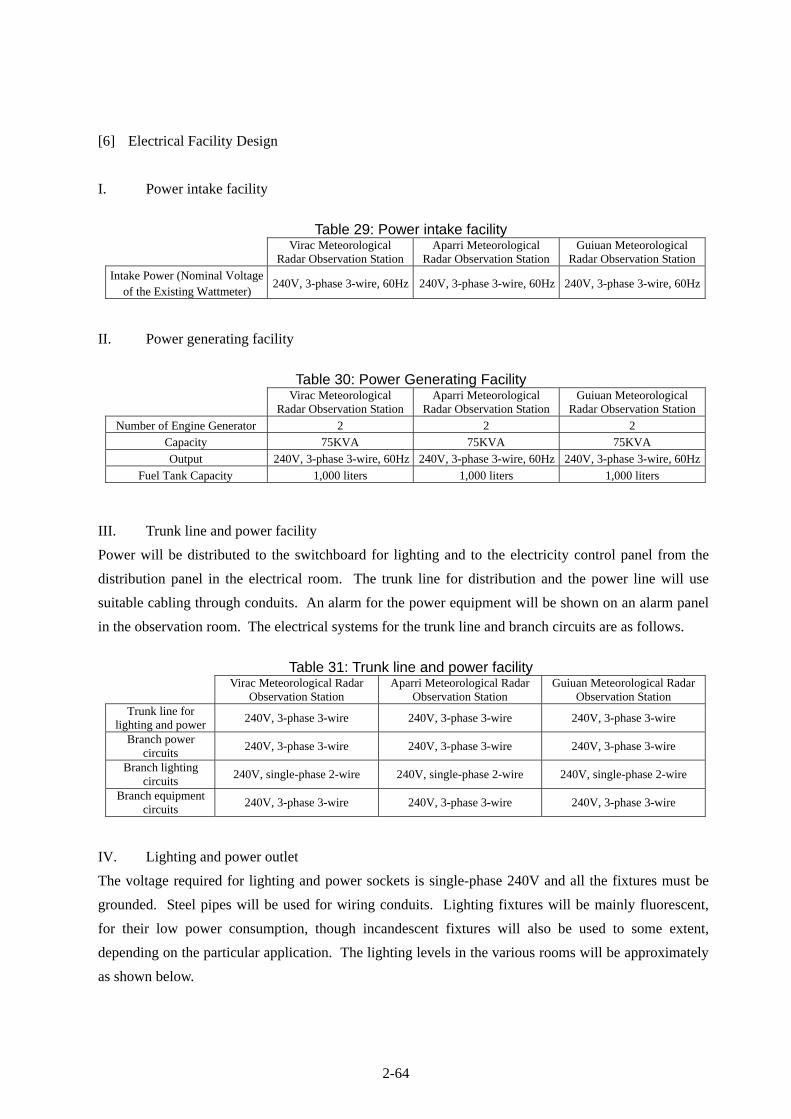
2-64
[6] Electrical Facility Design
I. Power intake facility
Table 29: Power intake facility
Virac Meteorological
Radar Observation StationAparri Meteorological
Radar Observation StationGuiuan Meteorological
Radar Observation Station
Intake Power (Nominal Voltage of the Existing Wattmeter)
240V, 3-phase 3-wire, 60Hz 240V, 3-phase 3-wire, 60Hz 240V, 3-phase 3-wire, 60Hz
II. Power generating facility
Table 30: Power Generating Facility
Virac Meteorological
Radar Observation StationAparri Meteorological
Radar Observation StationGuiuan Meteorological
Radar Observation Station
Number of Engine Generator 2 2 2
Capacity 75KVA 75KVA 75KVA
Output 240V, 3-phase 3-wire, 60Hz 240V, 3-phase 3-wire, 60Hz 240V, 3-phase 3-wire, 60Hz
Fuel Tank Capacity 1,000 liters 1,000 liters 1,000 liters
III. Trunk line and power facility
Power will be distributed to the switchboard for lighting and to the electricity control panel from the
distribution panel in the electrical room. The trunk line for distribution and the power line will use
suitable cabling through conduits. An alarm for the power equipment will be shown on an alarm panel
in the observation room. The electrical systems for the trunk line and branch circuits are as follows.
Table 31: Trunk line and power facility
Virac Meteorological Radar
Observation Station Aparri Meteorological Radar
Observation Station Guiuan Meteorological Radar
Observation Station Trunk line for
lighting and power 240V, 3-phase 3-wire 240V, 3-phase 3-wire 240V, 3-phase 3-wire
Branch power circuits
240V, 3-phase 3-wire 240V, 3-phase 3-wire 240V, 3-phase 3-wire
Branch lighting circuits
240V, single-phase 2-wire 240V, single-phase 2-wire 240V, single-phase 2-wire
Branch equipment circuits
240V, 3-phase 3-wire 240V, 3-phase 3-wire 240V, 3-phase 3-wire
IV. Lighting and power outlet
The voltage required for lighting and power sockets is single-phase 240V and all the fixtures must be
grounded. Steel pipes will be used for wiring conduits. Lighting fixtures will be mainly fluorescent,
for their low power consumption, though incandescent fixtures will also be used to some extent,
depending on the particular application. The lighting levels in the various rooms will be approximately
as shown below.

2-65
Table 32: Approximate lighting levels in the various rooms
Virac Meteorological Radar
Observation Station Aparri Meteorological Radar
Observation Station Guiuan Meteorological Radar
Observation Station Radome Room 200 Lx 200 Lx 200 Lx
Radar Equipment Room 300 Lx 300 Lx 300 Lx Observation Room 300 Lx 300 Lx 300 Lx
Data Analysis Room 300 Lx 300 Lx 300 Lx Data Storage Room 300 Lx 300 Lx 300 Lx Maintenance Room 300 Lx 300 Lx 300 Lx
Engine Generator Room 200 Lx 200 Lx 200 Lx Electricity Room 200 Lx 200 Lx 200 Lx
Power Supply Room 200 Lx 200 Lx 200 Lx Pump Room 200 Lx 200 Lx 200 Lx
Entrance Hall 200 Lx 200 Lx 200 Lx Other Rooms 200 Lx 200 Lx 200 Lx
General-purpose power outlets will be equipped with switches. Dedicated power outlets are required in
the radar equipment room, the observation room, the data analysis room, the data storage room and the
maintenance room for the Project computing equipment.
V. Telephone system
A service terminal box and a relay terminal box will be installed inside the radar tower buildings and
telephone lines will be installed to outlets in those rooms requiring a telephone.
VI. Intercom system
In order to control night shift personnel and visitors, intercom systems will be installed in the various
operating rooms (radar equipment room, observation room, maintenance room and data analysis room)
and outside of the building entrance, as a security measure.
VII. Alarm system
An alarm panel will be installed at the observation room. The following building equipment warnings
will be provided.
System failure of air-conditioning units in the radar equipment room
System failure of radar power backup unit
System failure and overheating of the engine generators
Breaker tripping of the distribution boards
VIII. Grounding system
Grounding cables for the equipment installed on 1st and 6th floors will be connected to the terminal box
for earthing. All the equipment to be installed in the electricity room and the power supply room will
be grounded via the terminal box, while the telephone equipment will be grounded by erecting a
grounding electrode and running a wire from there to the terminal box.

2-66
IX. Lightning protection system
A lightning rod will be installed on the top of the radome (included in the equipment portion of the
Project), with roof conductors on the concrete handrails of parapets, the roof top, and the observation
deck, to protect all the equipment and the radar tower buildings. A connection box will be placed at the
radome room for the lightning rod. Inside the building structure, copper tapes will be laid in a vinyl
pipe and grounded via the test terminal boxes.
X. Aviation obstruction light
A connection box for two obstruction lights on the top of the radome (which is part of the equipment
portion of the Project) will be placed in the radome room. Four obstruction lights, to be installed at the
observation deck, will be included in the building portion of the Project. For all of the obstruction
lights, two power distribution boards will be installed on the first floor and in the radar equipment room
and an automatic blinking switch will be installed on the first floor. All the aviation obstruction lights
will be furnished with surge arresters. Connecting work between the obstruction lights on the top of
radome and a connection box placed in the radome will be included in the equipment portion of the
Project.
XI. Fire detection and alarm system
Fire detectors will be installed in the radar equipment room, the electricity room, the power supply
room and the engine generator room, and an alarm system will be installed in the observation room.
[7] Water Supply, Drainage and Sanitary Fixture Design
I. Water supply system
The public water supply is not available in Virac, Aparri and Guiuan so that a well construction is
required for construction work of the radar tower building at each site. After the construction, this well
will be used as the water supply facility for the radar tower building. For the well water intake for the
radar tower building, a water supply gate valve will be installed.
II. Drainage system
Drainage will be divided into 2 systems - sewage and miscellaneous drainage. Sewage will primarily
be treated in a septic tank and then be permeated by a seepage pit into the ground. Miscellaneous
drainage will be fed directly into a seepage pit. A septic tank and a seepage pit must be constructed.
The capacity of the septic tank and seepage pit for the radar tower buildings have been designed for 12
PAGASA personnel in the operations area and for some visitors.
III. Sanitary fixtures
Closet bowl: European style
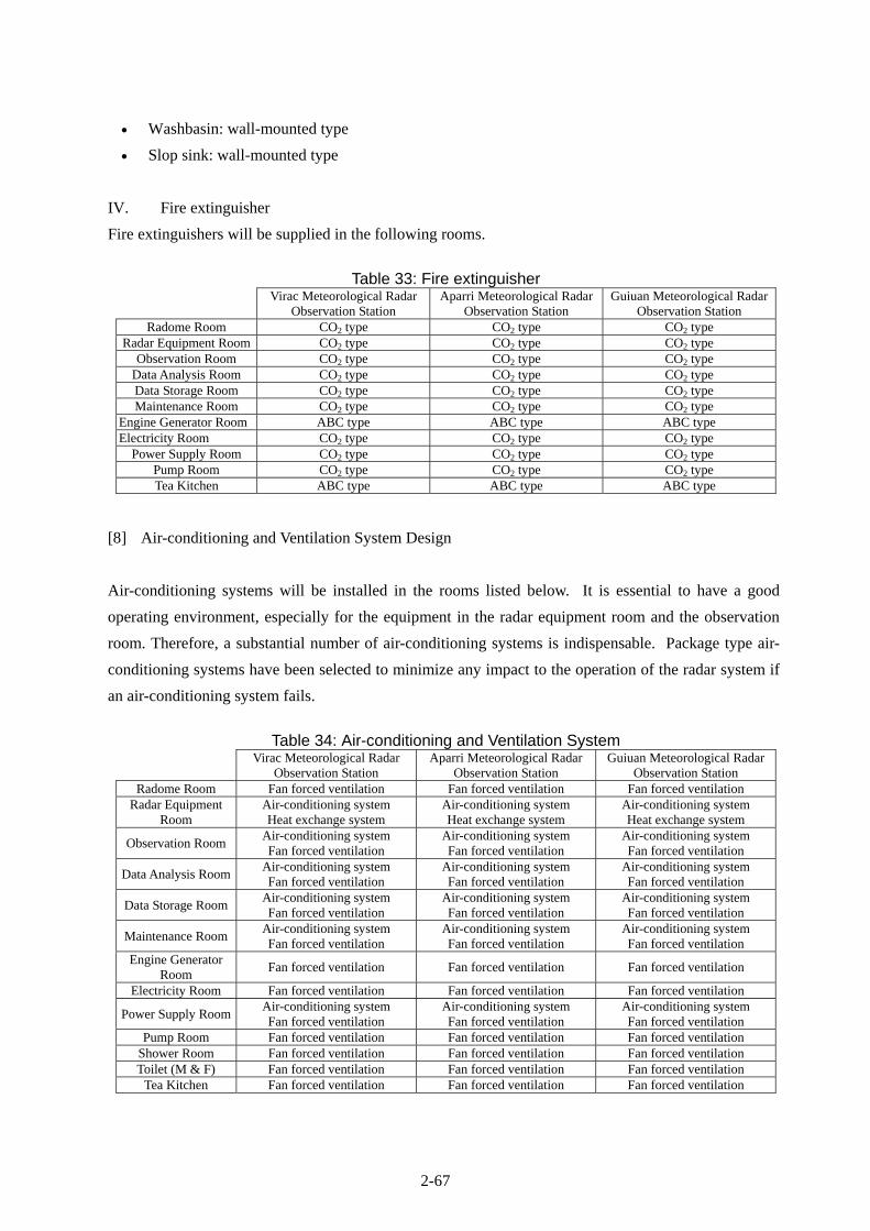
2-67
Washbasin: wall-mounted type
Slop sink: wall-mounted type
IV. Fire extinguisher
Fire extinguishers will be supplied in the following rooms.
Table 33: Fire extinguisher
Virac Meteorological Radar
Observation Station Aparri Meteorological Radar
Observation Station Guiuan Meteorological Radar
Observation Station Radome Room CO2 type CO2 type CO2 type
Radar Equipment Room CO2 type CO2 type CO2 type Observation Room CO2 type CO2 type CO2 type
Data Analysis Room CO2 type CO2 type CO2 type Data Storage Room CO2 type CO2 type CO2 type Maintenance Room CO2 type CO2 type CO2 type
Engine Generator Room ABC type ABC type ABC type Electricity Room CO2 type CO2 type CO2 type
Power Supply Room CO2 type CO2 type CO2 type Pump Room CO2 type CO2 type CO2 type Tea Kitchen ABC type ABC type ABC type
[8] Air-conditioning and Ventilation System Design
Air-conditioning systems will be installed in the rooms listed below. It is essential to have a good
operating environment, especially for the equipment in the radar equipment room and the observation
room. Therefore, a substantial number of air-conditioning systems is indispensable. Package type air-
conditioning systems have been selected to minimize any impact to the operation of the radar system if
an air-conditioning system fails.
Table 34: Air-conditioning and Ventilation System
Virac Meteorological Radar
Observation Station Aparri Meteorological Radar
Observation Station Guiuan Meteorological Radar
Observation Station Radome Room Fan forced ventilation Fan forced ventilation Fan forced ventilation
Radar Equipment Room
Air-conditioning system Heat exchange system
Air-conditioning system Heat exchange system
Air-conditioning system Heat exchange system
Observation Room Air-conditioning system Fan forced ventilation
Air-conditioning system Fan forced ventilation
Air-conditioning system Fan forced ventilation
Data Analysis Room Air-conditioning system Fan forced ventilation
Air-conditioning system Fan forced ventilation
Air-conditioning system Fan forced ventilation
Data Storage Room Air-conditioning system Fan forced ventilation
Air-conditioning system Fan forced ventilation
Air-conditioning system Fan forced ventilation
Maintenance Room Air-conditioning system Fan forced ventilation
Air-conditioning system Fan forced ventilation
Air-conditioning system Fan forced ventilation
Engine Generator Room
Fan forced ventilation Fan forced ventilation Fan forced ventilation
Electricity Room Fan forced ventilation Fan forced ventilation Fan forced ventilation
Power Supply Room Air-conditioning system Fan forced ventilation
Air-conditioning system Fan forced ventilation
Air-conditioning system Fan forced ventilation
Pump Room Fan forced ventilation Fan forced ventilation Fan forced ventilation Shower Room Fan forced ventilation Fan forced ventilation Fan forced ventilation Toilet (M & F) Fan forced ventilation Fan forced ventilation Fan forced ventilation
Tea Kitchen Fan forced ventilation Fan forced ventilation Fan forced ventilation

2-68
Ceiling fan forced ventilation will be installed in the tea kitchen and the toilets. Due to the heat
generated by the equipment in the radar equipment room, the engine generator room, the power supply
room, the electricity room, pump room, etc., forced ventilation systems will be adopted. Furthermore,
appropriate ventilation systems will be installed in other rooms to meet the following conditions.
<Environmental conditions>
Outside condition: 35C (maximum temperature)
Indoor condition: temperature 26C humidity 40-60%
In the radar equipment room and the power supply room: temperature 25C humidity 40-60%
2-69
The following diagrams of the building equipment plan for the radar tower buildings can be found in
the subsequent pages immediately hereafter.
<Virac, Aparri and Guiuan Meteorological Radar Tower Buildings>
Power Feeder Diagram : System Diagram 1 (SD-01)
Power Riser System : System Diagram 2 (SD-02)
Interphone System & Tel Diagram : System Diagram 3 (SD-03)
Riser Fire Alarm System : System Diagram 4 (SD-04)
Alarm System Diagram : System Diagram 5 (SD-05)
Riser Diagram Lighting Protection & Grounding System : System Diagram 6 (SD-06)
Riser Diagram Obstruction Lighting : System Diagram 7 (SD-07)
Water Supply & Drainage System : System Diagram 8 (SD-08)
Air-Conditioning & Ventilation Diagram : System Diagram 9 (SD-09)

2-70

2-71

2-72

2-73

2-74

2-75
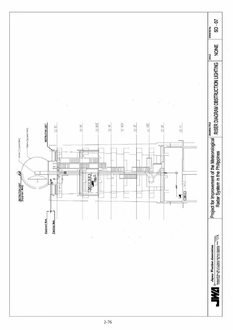
2-76

2-77

2-78