basic data report for monitor well cabin baby 1 …€¦ · basic data report for monitor well...
TRANSCRIPT

DOE/WIPP-04-3306
Basic Data ReportFor Monitor Well Cabin Baby 1 (CB-1)
Reconfiguration
Waste Isolation Pilot Plant
U.S. Department of EnergyCarlsbad Field Office
Revision 1
September 2008
This document supersedes DOE/WIPP-04-3306.

Basic Data Report for Monitor Well Cabin Baby 1 (CB-1) ReconfigurationDOE/WIPP-04-3306, Rev. 1
2
This document has been submitted as required to:
Office of Scientific and Technical InformationP.O. Box 62
Oak Ridge, TN 37831(615) 576-8401
Additional information about this document may be obtained by contacting the WIPPInformation Center at 1-800-336-9477. Copies may be obtained by contacting theNational Technical Information Service, U.S. Department of Commerce,5285 Port Royal Road, Springfield, VA 22101.
Processing and final preparation of this report was performed by the Waste IsolationPilot Plant Management and Operating Contractor for the U.S. Department of Energyunder Contract No. DE-AC04-01AL66444.

Basic Data Report for Monitor Well Cabin Baby 1 (CB-1) ReconfigurationDOE/WIPP-04-3306, Rev. 1
3
Basic Data ReportMonitor Well Cabin Baby 1 (CB-1)
(Waste Isolation Pilot Plant)
Richard A. SalnessWashington Regulatory and Environmental Services
P.O. Box 2078Carlsbad, NM 88220
September 2008

Basic Data Report for Monitor Well Cabin Baby 1 (CB-1) ReconfigurationDOE/WIPP-04-3306, Rev. 1
4
TABLE OF CONTENTS
ABBREVIATIONS AND ACRONYMS . . . . . . . . . . . . . . . . . . . . . . . . . . . . . . . . . . . . . . 5
1.0 INTRODUCTION . . . . . . . . . . . . . . . . . . . . . . . . . . . . . . . . . . . . . . . . . . . . . . . . 61.1 History of Monitor Well Cabin Baby 1 . . . . . . . . . . . . . . . . . . . . . . . . . . . 61.2 Regulatory Requirements for Reconfiguration of CB-1 . . . . . . . . . . . . . . 9
1.2.1 New Mexico Statutes . . . . . . . . . . . . . . . . . . . . . . . . . . . . . . . . . . 91.2.2 New Mexico OSE Rules and Regulations . . . . . . . . . . . . . . . . . . 101.2.3 State of New Mexico Energy, Minerals, and Natural
Resources Department Oil Conservation Commission(Order No. R-111-P) . . . . . . . . . . . . . . . . . . . . . . . . . . . . . . . . . . 11
2.0 WELL RECONFIGURATION . . . . . . . . . . . . . . . . . . . . . . . . . . . . . . . . . . . . . . 112.1 Removal of Packers and Tubing . . . . . . . . . . . . . . . . . . . . . . . . . . . . . . 122.2 Casing Preparation and Geophysical Logging . . . . . . . . . . . . . . . . . . . 122.3 Reconfiguration and Cement Emplacement . . . . . . . . . . . . . . . . . . . . . 132.4 Other Background . . . . . . . . . . . . . . . . . . . . . . . . . . . . . . . . . . . . . . . . . 15
3.0 WASTE MANAGEMENT . . . . . . . . . . . . . . . . . . . . . . . . . . . . . . . . . . . . . . . . . 15
4.0 SUMMARY . . . . . . . . . . . . . . . . . . . . . . . . . . . . . . . . . . . . . . . . . . . . . . . . . . . . 15
5.0 REFERENCES . . . . . . . . . . . . . . . . . . . . . . . . . . . . . . . . . . . . . . . . . . . . . . . . 15
Appendix A - Photographs . . . . . . . . . . . . . . . . . . . . . . . . . . . . . . . . . . . . . . . . . . . . . 16
Appendix B - Field Report by Baker Atlas Logging Engineer Charles Childress . . . . . 21
LIST OF FIGURES
Figure 1-1 - Location Map . . . . . . . . . . . . . . . . . . . . . . . . . . . . . . . . . . . . . . . . . . . . . . 7
Figure 1-2 - Configuration of Cabin Baby (CB-1) Before Reconfiguration (08/20/99) . 8
Figure 2-1 - Configuration of Cabin Baby (CB-1) After Reconfiguration (02/11/04) . 14

Basic Data Report for Monitor Well Cabin Baby 1 (CB-1) ReconfigurationDOE/WIPP-04-3306, Rev. 1
5
ABBREVIATIONS AND ACRONYMS
bgs below ground surfaceBLM U.S. Bureau of Land Management
CB-1 Cabin Baby Federal 1 Well|
DOE U.S. Department of Energy
EPA U.S. Environmental Protection Agency
ft foot/feet|
NMED New Mexico Environment Department
OSE Office of State Engineer (New Mexico)
P&A plugging and abandonment|PIP production-injection packerpsi pounds per square inch|
ROW right-of-way
SNL Sandia National Laboratories
WIPP Waste Isolation Pilot Plant

Basic Data Report for Monitor Well Cabin Baby 1 (CB-1) ReconfigurationDOE/WIPP-04-3306, Rev. 1
6
1.0 INTRODUCTION
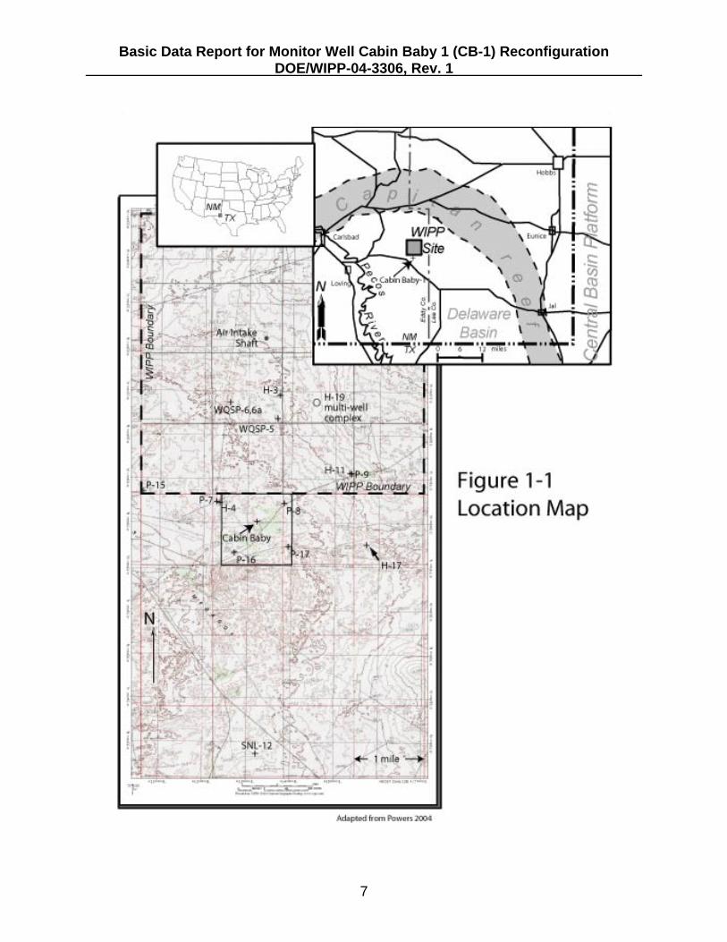
The Waste Isolation Pilot Plant (WIPP) is a U.S. Department of Energy (DOE) facilitydisposing of transuranic and mixed waste under the Hazardous Waste Facility Permit(Permit NM4890139088-TSDF, as amended) issued by the New Mexico EnvironmentDepartment (NMED). WIPP is located approximately 26 miles east of Carlsbad,New Mexico, in eastern Eddy County (Figure 1-1). Disposal panels are beingexcavated in the Permian Salado Formation at a depth of approximately 2,150 feet (ft)below ground surface (bgs).
Over the years, a number of groundwater monitor wells have been installed to monitortemporal and spatial changes in groundwater elevation and chemistry at WIPP. Manyof the wells used for this purpose were constructed of carbon steel casing that hasdeteriorated to varying degrees due to corrosion. For some wells, the deterioration hasled to failure of the well integrity. In such cases, the well must either be reconfigured orcompletely plugged, according to New Mexico Office of the State Engineer (OSE)regulatory requirements, to prevent commingling of groundwater from differentformations. Other wells are nearing the end of their useful life and/or are duplicative ofwells that serve the same purpose. Because of these integrity issues, WIPP has beguna program to plug and abandon wells that are no longer useful for the monitoringprogram or are redundant, and to reconfigure wells for future monitoring. One such wellis known as Cabin Baby Federal 1 (CB-1). In 2004, CB-1 was reconfigured to provideonly Bell Canyon Formation water level data. This basic data report provides ahistorical account of the well from the original installation to the current configuration.CB-1 was permitted by the New Mexico OSE and designated as "well C-2664." Thiswell has been part of the far-field monitoring network since it was reentered by WIPP in1978 up through reconfiguration in 2004. The well was used to obtain water levelelevations and hydraulic parameters from both the Bell Canyon Formation and theCulebra Member of the Rustler Formation.
1.1 History of Monitor Well Cabin Baby 1
CB-1 (OSE File #C-2664) is located 200 ft south of the southern WIPP site boundary inthe northeast quarter of Section 5, Township 23 south, Range 31 east (Figure 1-1). CB-1 was originally drilled in 1974 and 1975 as a petroleum wildcat well by theM.P. Grace Company. It was drilled to a depth of 4,150 ft bgs in the Bell CanyonFormation and cased with 13.375-inch outside diameter casing from ground surface to adepth of approximately 650 ft bgs, a few feet above the contact between the RustlerFormation and Salado Formation. M.P. Grace abandoned the well in 1974 after it wasproved to be a non-petroleum-producing "dry hole" (Beauheim 1983).
During 1978, D´Appolonia (on behalf of the DOE) deepened CB-1 to a total depth of4,290.6 ft and ran a caliper logging tool for borehole diameter measurements. From1983 through 1999, Sandia National Laboratories (SNL) set up the well with variationsof bridge plugs and production-injection packer (PIP) configurations for monitoring boththe Rustler and Bell Canyon Formations. In 1999, SNL installed a final PIP and bridgeplug configuration for multi-zone monitoring (Figure 1-2).
Basic Data Report for Monitor Well Cabin Baby 1 (CB-1) ReconfigurationDOE/WIPP-04-3306, Rev. 1
7
Figure 1-1 Location Map

Basic Data Report for Monitor Well Cabin Baby 1 (CB-1) ReconfigurationDOE/WIPP-04-3306, Rev. 1
8
Figure 1-2 Configuration of Cabin Baby (CB-1) BeforeReconfiguration (08/20/99)

Basic Data Report for Monitor Well Cabin Baby 1 (CB-1) ReconfigurationDOE/WIPP-04-3306, Rev. 1
9
M.P. Grace Company originally retained the right-of-way (ROW) reservation lease withthe U.S. Bureau of Land Management (BLM). This ROW was transferred to WIPP in1976 with special stipulations (ROW 107944). One of the stipulations required anymonitoring well which penetrated the salt section be cased. CB-1 was completed as anopen hole through the salt section. Therefore, based on this stipulation, the BLMrequired WIPP to reconfigure this well, or plug and abandon it, to prevent the saltsection exposure to the groundwater.
1.2 Regulatory Requirements for Reconfiguration of CB-1
Prior to initiating the plugging and abandonment (P&A)/reconfiguration program theapplicable regulations regarding the subject were analyzed. The following regulationswere reviewed for this analysis:
C New Mexico Statutes Annotated 1978, Section 72-14 regarding drilling, casing,repairing, and abandonment of artesian wells.
C New Mexico OSE Rules and Regulations regarding application filing for welldrilling, repair, and P&A.
C State of New Mexico Energy, Minerals, and Natural Resources Department OilConservation Commission (Order No. R-111-P) regarding the protection ofmineral resources from commingling or leaking water sources.
C BLM Stipulations for ROWs NM107944 and NM108365.
In the following sections there are terms used which are unique to the geology ofsoutheastern New Mexico.
C "Potash area" is defined in Oil Conservation Division Order No. R-111-P. Thisrepresents the area of which potash mining operations are now in progress, or inwhich core tests indicated commercial potash reserves. This area is coterminouswith the Known Potash Leasing Area, as determined by the BLM. CB-1 islocated in this area and is subject to these regulations.
C "Salt section" refers to the Salado Formation in which the McNutt Potash unit isdeposited. Figure 2-1 depicts the Salado Formation graphically.
The applicable portions of the listed regulations are described in the following sections.
1.2.1 New Mexico Statutes
Section 72-13-4 of the New Mexico Statutes Annotated prescribes the rules andregulations governing the drilling, casing, repairing, and abandonment of artesian wells. This section authorizes the State Engineer "to prescribe and enforce reasonable rulesand regulations consistent with terms of this act." Additionally, this section states thatapplication to the State Engineer is required to drill, repair, plug or abandon an artesian

Basic Data Report for Monitor Well Cabin Baby 1 (CB-1) ReconfigurationDOE/WIPP-04-3306, Rev. 1
10
well. All wells completed in the Magenta and Culebra Members of the RustlerFormation are considered artesian.
1.2.2 New Mexico OSE Rules and Regulations
Article 1-1 Filing
This Article defines the necessary action for filing an application to drill, repair, plug orabandon wells in the state of New Mexico. Prior to repair/reconfiguration activities theOSE must be notified through the application process of WIPP's intent torepair/reconfigure the monitoring wells at the site.
Article 4-16 Casing-Cementing-Testing
This Article describes the cementing and cement testing approval requirements foremplacing cement plugs in wells and boreholes. This is the only regulation thatprescribes types of cement, mixture ratios, and additive requirements. It is primarily forcasing cementation during well installation, but is also acceptable for plugging.
This article specifies pump and plug methodology. The primary specification in thisArticle is the use of Class C neat cement at a density of fifteen pounds per gallon.
This Article also specifies that cementing/P&A programs shall be witnessed andapproved by an authorized representative of the State Engineer.
Article 4-19 Artesian Wells - Repair
This article provides specifications that are most applicable to the P&A program. Priorto commencement of repairs (i.e., reconfiguration), a representative of the StateEngineer must inspect the well to "determine if the condition of the well is such that itmay be repaired." Additionally, "the hole shall be open to allow the entrance ofequipment for well logging and leakage measurement," which implies a degree of wellintegrity testing (e.g., cement bond log, ultrasonic imaging log).
Article 4-19.1 Plugging
This section prescribes that "All work shall be done under the supervision of the StateEngineer or his representative, or a representative of the appropriate ArtesianConservancy District who shall designate the amount of cement to be used and thedepths at which cement plugs shall be set."
Article 4-20 Test or Exploratory Wells
Article 4-20 contains the rules for test or exploratory wells, which all the monitoring wellsqualify. However, for P&A (Article 4-20.2) of these wells the regulations defer to theartesian specifications contained in Article 4-19. Additionally, this section further states"Such wells shall be plugged in accordance with Article 4-19.1 so that fluids will be

Basic Data Report for Monitor Well Cabin Baby 1 (CB-1) ReconfigurationDOE/WIPP-04-3306, Rev. 1
11
permanently confined to the specific strata in which they were originally encountered,thus preventing the commingling of water bearing zones."
1.2.3 State of New Mexico Energy, Minerals, and Natural Resources DepartmentOil Conservation Commission (Order No. R-111-P)
These regulations are designed to protect mineral resources from commingling orleaking water sources. The primary concern here is the potash area and protection ofthe salt section and any water bearing horizon. The regulations state:
1. "All wells heretofore and hereafter drilled within the potash area shall be pluggedin a manner and in accordance with the general rules or field rules established bythe Division that will provide a solid cement plug through the salt section and anywater-bearing horizon and prevent liquids or gasses from entering the hole aboveor below the salt section."
2. "The fluid used to mix the cement shall be saturated with the salts common to thesalt section penetrated and with suitable proportions but not more than three(3) percent of calcium chloride by weight of cement being considered the desiredmixture possible."
This regulation was discussed with the Oil Conservation Commission and BLMregarding applicability to cementing for reconfiguration. It was determinedthrough this discussion that it applied to drilling of wells and not thereconfiguration application for this program.
2.0 WELL RECONFIGURATION
Well CB-1 was reconfigured during January and February 2004 to monitor only the BellCanyon Formation. The purpose of this reconfiguration was twofold. First, when thewell was drilled, the completion was not compliant with OSE and BLM in that waterbearing formations were possibly commingling and the Salado Formation was notsealed off with well casing and/or cement. Second, water levels in the upper Culebrasection of this well had been rising over the years for reasons unknown, yet possiblydue to failed packer elements.
Figure 1-2 shows the configuration of well CB-1, as built in 1999, prior to thisreconfiguration. The center of the shallow packer was set at a depth of 608 ft bgs, whilethe center of the deeper packer isolating the Bell Canyon Formation was set at 4,290 ftbgs (Appendix A). Available data for these packers indicated they were Baker Atlaswater-inflatable packers with a shear pressure of 20,000 pounds per square inch (psi).
The new configuration for CB-1 was planned to monitor only the Bell Canyon Formation. To do this the existing packers and tubing needed to be removed from the borehole, thecasing needed to be prepared for geophysical logging, new tubing and packers neededto be installed, and the well cemented from the packer to the surface. The followingsections describe the reconfiguration process for CB-1.

Basic Data Report for Monitor Well Cabin Baby 1 (CB-1) ReconfigurationDOE/WIPP-04-3306, Rev. 1
12
2.1 Removal of Packers and Tubing
Removal of the packers and tubing took place during the period of January 21-23, 2004. Removal involved connecting the drill rig elevator to the existing tubing and applyingenough pressure to break the shear pin and drain the packer fluid, thus relieving thepressure, then pulling the remaining packer mandrel assembly and element from thehole. The shallow packer sheared at 50,000 psi after several attempts to release it. The packer was allowed to sit and drain for 15 minutes prior to attempting to release thedeeper packer.
After a period to allow the shallow packer to drain an attempt was made to release thelower packer from the hole. Several attempts at tension pressures exceeding60,000 psi were made to release the shear pin on the lower packer, without success. The decision was made to use a free-point indicator tool to determine the percent of thepacker that was bound in the hole. The free-point indicator tool measures the amountof stretch in the tubing when force is applied. The free-point indicator tool determinedthe lower 70% of the deep packer was bound up. At this point it was determined to usea perforating tool to assist in releasing the packer. Following discussions withWashington Regulatory and Environmental Services Site Environmental Complianceregarding use of shot, a single charge was detonated at a depth of 4,021 ft bgs. Afterdetonation the drill rig pulled on the tubing string once again, and after several attempts,the packer released from the hole and the tubing string with both packers were removed(Appendix A).
2.2 Casing Preparation and Geophysical Logging
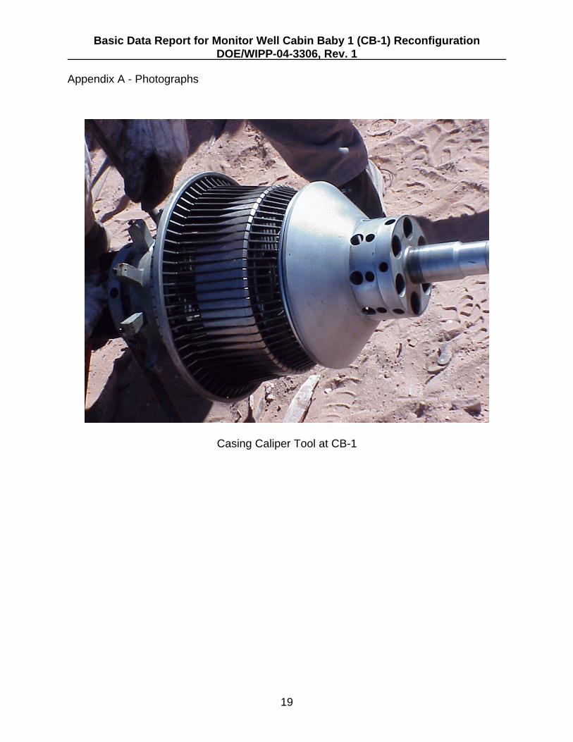
Casing preparation and geophysical logging took place during the period ofJanuary 24-28, 2004. Following the removal of the tubing and packers, the casing wasscraped to remove debris and significant pitting from the casing surface in preparationfor geophysical logging. Baker Atlas, a division of Baker Hughes performed thegeophysical logging. The types of geophysical logs performed were 3-Arm Caliper Log,Segment Cement Bond Log, and Profile Caliper Log.
The 3-Arm Dialog Profile Caliper Log was performed to provide information regardingthe diameter of the borehole, and by inference, the condition of the open-hole section ofthe borehole. These data provided the degree of halite dissolution and/or creep in theborehole, other formation stability, and the ability to determine optimum packerplacement and preliminary concrete volumes for plugging the open sections betweenthe casing and the new packer. The greatest measured borehole diameter was inexcess of 18 inches at depths of 660 ft bgs and 3,804 ft bgs, in the Rustler Formationand between the Halite I (HI) and the Anhydrite I (AI) units of the Castile Formation,respectively. Other than these locations, the open hole appeared to be stable. Basedon the logs it was determined the best location to install the center of the reconfigurationpacker in the AI at a depth of 4,015 ft bgs. This log also confirmed the total depth of theborehole to be 4,290 ft bgs.

Basic Data Report for Monitor Well Cabin Baby 1 (CB-1) ReconfigurationDOE/WIPP-04-3306, Rev. 1
13
The Segment Cement Bond Log was performed to evaluate the integrity of the cementbond with the casing and with the adjacent formation to assure there is no ability forinterstitial commingling of groundwater between water bearing zones (i.e., Magenta andCulebra Members). The bond log was run from the top of the casing to a depth of616 ft bgs. It was not run into the casing shoe to avoid the possibility of getting the toolstuck in the hole. According to the Baker Atlas logging Engineer, Charles Childers, theresulting analysis from this log indicated the cement bond is excellent with noindications of channeling and that there is bonding to both the casing and formation(Appendix B).
The Profile Caliper Log was performed to measure the wall thickness of the casing todetermine if detrimental corrosion had occurred since installation that would requirecorrective action prior to full well reconfiguration. According to the Baker Atlas loggingEngineer, Charles Childers, the quality of the pipe is very good and did not appear to bedamaged (Appendix B). Copies of all logs are contained in the project files at the WIPPsite.
2.3 Reconfiguration and Cement Emplacement
After geophysical logging and determining the packer placement, the tubing and packerwere installed in the borehole during February 3-5, 2004. Materials consisted of2.875-inch, 6.5#, J-55 tubing coated with Tube-Kote 70 (TK-70) manufactured byTuboscope®. TK-70 is a thick film, epoxy coating especially suited for harshenvironments. TK-70 resists hydrocarbons and provides outstanding protection of thesteel tubing. TK-70 resists most mechanical damage normally experienced in the fieldwhile retaining a high level of corrosion resistance. TK-70 was used on the tubing toprovide a longer life of the monitor well than typical steel tubing would. This materialwas used because this well is used to monitor the hydrostatic head in the Bell CanyonFormation, and due to the corrosive nature of the aqueous chemistry of this formation, itwas important to impede the reaction with bare steel. For this application, 79 ft of tubingthat is below the packer and submersed in the Bell Canyon was coated both on theinside and the outside with TK-70. The remaining tubing from the top of the packer tothe surface was coated only on the inside to prevent corrosion from contact with BellCanyon water and with ambient air (Figure 2-1).
Figure 2-1 shows the as-built construction of CB-1 after reconfiguration. Tubing coatedon the inside with TK-70 was installed from the surface to the top of the packer atapproximately 4,007 ft bgs. Tubing coated on the inside and outside was installed fromthe bottom of the packer to a depth of 4,097 ft bgs. The same deep packer removedfrom CB-1 was redressed and used for the new configuration. The packer wasredressed by Weatherford Tool Company. It is a 10.375-inch open hole Baker Atlasinflatable packer (Appendix A) with the center of the packer set at 4,015 ft bgs.
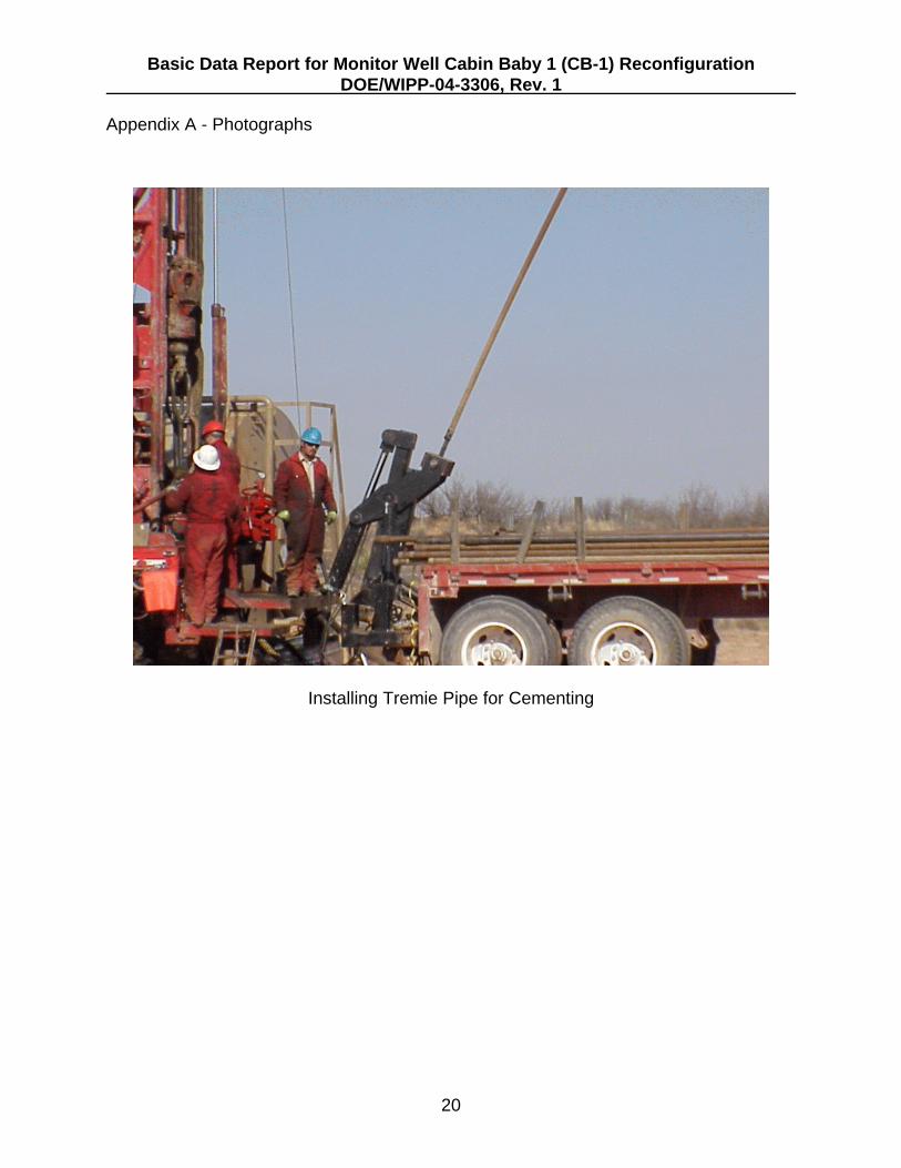
Following installation of the tubing and packer the well was prepared for cementing. Tremie pipe was placed into the hole to a depth of 3,997 ft bgs, 10 ft above the top ofthe packer. Portland cement was prepared at the Lafarge materials plant in Carlsbad,|

Basic Data Report for Monitor Well Cabin Baby 1 (CB-1) ReconfigurationDOE/WIPP-04-3306, Rev. 1
14
New Mexico, and trucked to the well pad for emplacement. Cement from the trucks waspoured into a tub at ground surface and pumped by tremie pipe into the borehole in lifts.
The first lift created a 100-ft column of cement on top of the packer. This column wasallowed to cure overnight before more lifts were emplaced. At total of 2,687 cubic ft ofcement was used to complete the configuration as presented in Figure 2-1. Cementwas emplaced in the well over the course of five days (February 6-10, 2004) and fourlifts. Lifts consisted of 95, 864, 648, and 1,080 cubic ft of cement, respectively.
Figure 2-1 - Configuration of Cabin Baby (CB-1) After Reconfiguration (02/11/04)

Basic Data Report for Monitor Well Cabin Baby 1 (CB-1) ReconfigurationDOE/WIPP-04-3306, Rev. 1
15
2.4 Other Background
Well work-over services were performed by Stewart Brothers Drilling Company, 306Airport Road, Milan, New Mexico, under contract with Washington TRU Solutions LLC. Their New Mexico Water Well Driller License number is WD-331. Fishing tool servicesand packers were provided by Weatherford, 2117 N. French Drive, Hobbs, New Mexico88241. Geophysical logging was conducted by Baker Atlas, 11717 County Road 125West, Midland, Texas 79711. Mike Stapleton of the New Mexico OSE witnessedcement emplacement.
3.0 WASTE MANAGEMENT
During the emplacement of cement during plugging activities the brine water in theborehole was displaced to the surface. The water was captured from the wellheadcasing through a right-angle discharge pipe at the surface, then a transfer pump movedthe water from the trough into a 500-barrel fractionation tank for storage prior todisposal. The captured water was characterized for disposal by analysis using ToxicityCharacteristic Leaching Procedures. The analyses were performed for ResourceConservation and Recovery Act metals. All analyses indicated the brine waternonhazardous. Following receipt of the analytical results the brine water collected atCB-1 was disposed in the lined H-19 evaporation pond. A total of 500 barrels weredisposed in the H-19 evaporation pond.
Analytical reports and disposal records are retained onsite in the site compliancerecords. These records may be obtained upon request.
4.0 SUMMARY
Well CB-1 was originally drilled in 1974 and 1975 as a petroleum wildcat well by theM.P. Grace Company. It was drilled to a depth of 4,150 ft bgs in the Bell CanyonFormation. M.P. Grace abandoned the well in 1974 after it was proved to be a "dryhole" (Beauheim 1983). From 1983 through 1999, SNL set up the well with variations ofbridge plugs and PIP configurations for monitoring both the Rustler and Bell CanyonFormations. In 1999, SNL installed a final PIP and bridge plug configuration formulti-zone monitoring.
Due to BLM requirements and uncertainty in water level measurements, the well wasreconfigured to only monitor the hydrostatic head in the Bell Canyon Formation. Thereconfiguration efforts took place during January 20 through February 10, 2004, andconsisted of, in order, removal of packers, scraping the casing, performing geophysicallogging, installation of a packer and tubing and emplacing cement from the packer tosurface.
5.0 REFERENCES
Beauheim, R. L., B. W. Hassinger, J. A. Klaiber, Basic Data Report for Borehole CabinBaby-1 Deepening and Hydrologic Testing. 1983.

Appendix A - Photographs
Basic Data Report for Monitor Well Cabin Baby 1 (CB-1) ReconfigurationDOE/WIPP-04-3306, Rev. 1
16
Removed Packers from CB-1Packer on Left is the Deep Packer (Figure 1-2)Packer on Right is the Shallow Packer (Figure 1-2)

Appendix A - Photographs
Basic Data Report for Monitor Well Cabin Baby 1 (CB-1) ReconfigurationDOE/WIPP-04-3306, Rev. 1
17
Casing Scraper at CB-1

Appendix A - Photographs
Basic Data Report for Monitor Well Cabin Baby 1 (CB-1) ReconfigurationDOE/WIPP-04-3306, Rev. 1
18
3-Arm Caliper Logging Tool
Appendix A - Photographs
Basic Data Report for Monitor Well Cabin Baby 1 (CB-1) ReconfigurationDOE/WIPP-04-3306, Rev. 1
19
Casing Caliper Tool at CB-1
Appendix A - Photographs
Basic Data Report for Monitor Well Cabin Baby 1 (CB-1) ReconfigurationDOE/WIPP-04-3306, Rev. 1
20
Installing Tremie Pipe for Cementing

Basic Data Report for Monitor Well Cabin Baby 1 (CB-1) ReconfigurationDOE/WIPP-04-3306, Rev. 1
21
Appendix B - Field Report by Baker Atlas Logging Engineer Charles Childress
Log Analysis of the Cabin Baby 1
The cement bond quality is excellent with no indications of channeling. There isbonding to both the pipe and the formation.
The Profile caliper log measures wall thickness of the casing. The quality of the pipeoverall is very good.
The 3-arm caliper log is self-explanatory. It shows the borehole diameter in inches.
The Tools
The Segment cement bond log tool is the conventional low frequency acoustic bondtool. This tool can only be used for the overall quality of the cement. It will indicatechannels but will not output a map of the channels.
The casing inspection tool used was a high frequency acoustic tool. This tool arrives atthe thickness by the frequencies returning to the receivers. It obtains the internaldiameter from the travel time of the sonic signal. This tool is only designed for anoverall quality of the pipe. It is unlikely to determine small holes since it is not takingreadings on 100% of the pipe.
The caliper tool is a 3-armed caliper tool which takes readings to measure the boreholediameter. This tool does not calculate hole volumes.
Charles ChildersLogging EngineerPermian Cased Hole432 563-6293