(basic certificate curriculumand syllabus …
TRANSCRIPT

KEMENTERIAN PERHUBUNGAN
DIREKTORAT JENDERAL PERHUBUNGAN UDARA
PERATURAN DIREKTUR JENDERAL PERHUBUNGAN UDARA
NOMOR : KP 269 Tahun 2017
TENTANG
PEDOMAN TEKNIS OPERASIONAL
PERATURAN KESELAMATAN PENERBANGAN SIPIL BAGIAN 147-02
(ADVISORY CIRCULAR 147-02)
PENYUSUNAN KURIKULUM DAN SILABUS SERTIFIKAT DASAR
(BASIC CERTIFICATE CURRICULUM AND SYLLABUS DEVELOPMENT)
DENGAN RAHMAT TUHAN YANG MAHA ESA
DIREKTUR JENDERAL PERHUBUNGAN UDARA,
Menimbang : a. bahwa pada butir 147.9 dalam Lampiran Peraturan
Menteri Perhubungan Nomor PM 85 Tahun 2017
tentang Peraturan Keselamatan Penerbangan Sipil
Bagian 147 (Civil Aviation Safety Regulations Part 147)
Organisasi Pusat Pelatihan Perawatan Pesawat Udara
(Aircraft Maintenance Training Organization) Edisi 1
Amandemen 0 (Edition 1 Amendment 0) telah mengatur
bahwa kurikulum dan silabus menjadi persyaratan
permohonan sertifikat organisasi pusat pelatihan
perawatan pesawat udara;
b. bahwa untuk memberikan panduan bagi pemohon
sertifikat organisasi pusat pelatihan perawatan
pesawat udara dalam menyusun kurikulum dan
silabus untuk sertifikat dasar, perlu disusun pedoman
teknis operasional;

c. bahwa berdasarkan pertimbangan sebagaimana
dimaksud dalam huruf a dan huruf b, perlu
menetapkan Peraturan Direktur Jenderal Perhubungan
Udara Tentang Pedoman Teknis Operasional Peraturan
Keselamatan Penerbangan Sipil Bagian 147-02
(Advisory Circular 147-02) Penyusunan Kurikulum Dan
Silabus Sertifikat Dasar (Basic Certificate Curriculum
And Syllabus Development);
Mengingat : 1. Undang-Undang Nomor 1 Tahun 2009 tentang
Penerbangan (Lembaran Negara Republik Indonesia
Tahun 2009 Nomor 1, Tambahan Lembaran Negara
Republik Indonesia Nomor 4956);
2. Peraturan Presiden Nomor 7 Tahun 2015 tentang
Organisasi Kementerian Negara (Lembaran Negara
Republik Indonesia Tahun 2015 Nomor 8);
3. Peraturan Presiden Nomor 40 Tahun 2015 tentang
Kementerian Perhubungan (Lembaran Negara Republik
Indonesia Tahun 2015 Nomor 75);
4. Peraturan Menteri Perhubungan Nomor PM 189 Tahun
2015 tentang Organisasi dan Tata Kerja Kementerian
Perhubungan (Berita Negara Republik Indonesia Tahun
2015 Nomor 1844) sebagaimana telah beberapa kali
diubah, terakhir dengan dengan Peraturan Menteri
Perhubungan Nomor PM 44 Tahun 2017 tentang
Perubahan Kedua atas Peraturan Menteri
Perhubungan Nomor PM 189 Tahun 2015 tentang
Organisasi dan Tata Kerja Kementerian Perhubungan
(Berita Negara Republik Indonesia Tahun 2017 Nomor
816);

5. Peraturan Menteri Perhubungan Nomor PM 85 Tahun
2017 tentang Peraturan Keselamatan Penerbangan
Sipil Bagian 147 (Civil Aviation Safety Regulations Part
147) Organisasi Pusat Pelatihan Perawatan Pesawat
Udara (Aircraft Maintenance Training Organization)
Edisi 1 Amandemen 0 (Edition 1 Amendment 0);
MEMUTUSKAN:
Menetapkan : PERATURAN DIREKTUR JENDERAL PERHUBUNGAN
UDARA TENTANG PEDOMAN TEKNIS OPERASIONAL
PERATURAN KESELAMATAN PENERBANGAN SIPIL BAGIAN
147-02 (ADVISORY CIRCULAR 147-02) PENYUSUNAN
KURIKULUM DAN SILABUS SERTIFIKAT DASAR (BASIC
CERTIFICATE CURRICULUM AND SYLLABUS DEVELOPMENT).
Pasal 1
Memberlakukan Pedoman Teknis Operasional Peraturan
Keselamatan Penerbangan Sipil Bagian 147-02 (Advisory
Circular 147-02) Penyusunan Kurikulum Dan Silabus
Sertifikat Dasar (Basic Certificate Curriculum And Syllabus
Development) sebagaimana tercantum dalam Lampiran yang
merupakan bagian tak terpisahkan dari Peraturan Direktur
Jenderal ini.
Pasal 2
Pada saat Peraturan ini mulai berlaku, Keputusan Direktur
Jenderal Perhubungan Udara Nomor SKEP/282/X/2000
tentang Advisory Circular 65-2 Aircraft Maintenance Engineer
Licence Examination Syllabus, dicabut dan dinyatakan tidak
berlaku.
Pasal 3
Direktur Jenderal Perhubungan Udara melakukan
pengawasan terhadap pelaksanaan Peraturan ini.

Pasal 4
Peraturan ini mulai berlaku sejak tanggal ditetapkan.
Ditetapkan di Jakarta
pada tanggal 2 OKTOBER 2017
DIREKTUR JENDERAL PERHUBUNGAN UDARA
ttd
Dr. Ir. AGUS SANTOSO, M.Sc
F R
Salinan sesuai aslinyaKEPALA BAGIAN HUKUM
SB*.«
ENDAH PURNAMA SARI
Pembina/ (IV/ a)NIP. 19680704 199503 2 00

LAMPIRAN
PERATURAN DIREKTUR JENDERAL PERHUBUNGAN UDARANOMOR : KP 269 TAHUN 2017
TANGGAL : 3 OKTOBER 2017
ADVISORY CIRCULAR
AC 147-02
BASIC CERTIFICATE CURRICULUM AND
SYLLABUS DEVELOPMENT
Edition
Amendment
Date
1
0
REPUBLIC OF INDONESIA - MINISTRY OF TRANSFORATIONSDIRECTORATE GENERAL OF CIVIL AVIATIONJAKARTA - INDONESIA

AC 147-02
AMENDMENT RECORD LIST
Amendment No. Issue Date Inserted By Insertion Date
Original

Amendment
No.
Edition 1
SUMMARY OF AMENDMENTS
Source/s
ICAO Doc 7192
Part D-1 Aircraft
Maintenance
Subject/s
Training Manual
AC 147-02
Approved
ii
1. PURPOSE
2. REFERENCES
3. CANCELLATION
4. AMENDEMENT
linan sesuai aslinya)PALA BAGIAN HUKUM
ENDAH PURNAMA SARI
AC 147-02
FOREWORD
This Advisory Circular provides informationabout some of the regulations in part 147 anddescribes the policies of the DGCA inadministering those regulations.
This Advisory Circular is to provide guidence toApproved Maintenance Training Organizations todevelop curriculum and syllabus for BasicAircraft Training.
This Advisory Circular should be used inaccordance with the applicable regulations.
(SKEP/262/X/2000) Advisory 65-2 AircraftMaintenance Engineer License ExaminationSyllabus is cancelled.
Amendment of this Staff Instruction shall beapproved by the Director General of Civil Aviation.
DIRECTOR GENERAL OF CIVIL AVIATION
ttd
Dr. Ir. AGUS SANTOSO, M.Sc
Pembina/(IV/a)NIP. 19680704 199503 2 00
Page 3 of 220

AC 147-02
Table of Contents
1. AMENDMENT RECORD LIST i
2. SUMMARY OF AMENDMENTS ii
3. FOREWORD 3
CHAPTER I. INTRODUCTION 19
A. PURPOSE 19
B. GENERAL 19
CHAPTER 2. BASIC CERTIFICATE CURRICULUM 26
A. CURRICULUM REQUIREMENTS 26
1.1 Hours of Instruction 26
1.2 Training Subject: knowledge 27
1.3 Practical Application Projects 28
1.4 Test 29
B. REVISIONS TO THE CURRICULUM 29
C. CREDIT FOR PREVIOUS INSTRUCTION OR EXPERIENCE 29
APPENDIX 1 31
A. RECOMMENDED TRAINING SUBJECT FOR LICENSE & BASIC
CERTIFICATE CATEGORIZATION 31
B. Recommended Training Subject Teaching Level 33
C. TRAINING SUBJECT: KNOWLEDGE 46
1. AVIATION REGULATIONS 46
TRAINING OBJECTIVES 46
REQUIRED KNOWLEDGE, SKILLS, AND ATTITUDES 46
1.1 International and State aviation laws 46
1.2 Airworthiness requirements 47
1.3 Civil aviation operating regulations (CASR 21, 43, 65, & 91) 47
1.4 Air transport operations 48
1.5 Organization and management of the operator 48
1.6 Operator economics related to maintenance 49
1.7 Approved maintenance organizations (AMOs) 50
1.8 Aircraft maintenance licence requirements 50
1.9 The role of the State aviation regulatory body 51
1.10 Aircraft certification, documents and maintenance 51
a. Aircraft, propeller and engine Type Certification 51
b. Individual aircraft certification 51
Page 4 of 217

AC 147-02
1.11 Issue of Certificate of Airworthiness (C of A) and Certificate ofRegistration (C of R) 52
Requirements for continuing airworthiness 52
2. NATURAL SCIENCE 53
REQUIRED KNOWLEDGE, SKILLS AND ATTITUDES 53
2.1 MATHEMATICS: 53
a. Arithmetic 53
b. Algebra 53
c. Geometry 53
d. Trigonometry 53
e. Logarithms 54
f. Calculators 54
g. Differential and integral calculus 54
2.2 PHYSICS: 54
a. Mechanics 54
b. Heat 55
c. Light 56
d. Electricity and magnetism 56
e. Wave motion and sound 58
2.3 TECHNICAL DRAWING 58
a. Introduction 58
b. Practice with drawing instruments 58
c. Simple orthographic projections 58
d. Simple isometric projections 58
e. Geometric construction 59
f. Practice in sketching 59
g. Orthographic projection 59
h. Shop terms and processes 59
i. Assembly drawing 59
j. Auxiliary projections 60
k. Axonometric projection 60
1. Oblique projection 60
m. Circuit layout 60
n. Exercises in blueprint reading 60
o. Exercises in engineering design 60
2.4 CHEMISTRY: 60
3. AERODYNAMICS: AEROPLANE 61
Page 5 of 217

AC 147-02
REQUIRED KNOWLEDGE, SKILLS AND ATTITUDES 61
3.1 Aerodynamic physics 61
3.2 Airflow 61
3.3 Aerofoils 61
3.4 Conditions of flight 62
3.5 Flight controls 62
3.6 High speed flight 63
4. AERODYNAMICS: HELICOPTER 65
REQUIRED KNOWLEDGE, SKILLS AND ATTITUDES 65
4.1 Introduction 65
4.2 Rotary wing theory of flight 65
4.3 Rotary wing stability 66
5. MAINTENANCE PRACTICES 67
REQUIRED KNOWLEDGE, SKILLSAND ATTITUDES 67
5.1 Aircraft, hangar and workshop safety precautions 67
5.2 Principles of workshop practice 67
5.3 General purpose tools 67
5.4 General purpose power tools 67
5.5 Precision measuring tools 67
5.6 Screw threads 67
5.7 Bolts, studs, screws and fasteners 68
5.8 Fits and clearances 68
5.9 Maintenance data, engineering drawings and diagrams 68
5.10 Electrical cables and connectors (as applicable to a mechanical AME)69
5.11 Aircraft fasteners 69
5.12 Pipes and unions 69
5.13 Springs 70
5.14 Bearings 70
5.15 Gears 70
5.16 Transmission systems 70
5.17 Cables and wires used in aircraft 70
5.18 Sheet metal work 71
5.19 Machine tool operation 71
5.20 Forging, welding, brazing, soldering and bonding 71
5.21 Aircraft materials: Ferrous 72
5.22 Aircraft materials: Non-ferrous 72
Page 6 of 217

AC 147-02
5.23 Aircraft materials: Composite/Non-metallic 72
5.24 Corrosion 73
5.25 Aircraft corrosion control 73
5.26 Non-destructive testing (NDT)/Non-destructive inspection (NDI). 74
5.27 Basic electricity 74
5.28 Aircraft handling 74
6. AIRCRAFT SYSTEMS AND STRUCTURES: AEROPLANE 75
REQUIRED KNOWLEDGE, SKILLS AND ATTITUDES 75
6.1 Mechanical control components: construction and function 75
6.2 Hydraulic system 75
6.3 Pneumatic and air systems 75
6.4 Airframe structures: General concepts 76
6.5 Wings, primary and auxiliary control surfaces 76
6.6 Inspection of structures 77
6.7 Airframe symmetry 78
6.8 Fastener installation 78
6.9 Sheet metal repair in aircraft 79
6.10 Tubular structure repair 79
6.11 Window and windshield repairs 79
6.12 Pressurized structures 79
6.13 Surface protection and paint systems 80
6.14 Landing gear and associated systems 80
6.15 Ice and rain protection 81
6.16 Cabin systems and installation 81
6.17 Environmental, air conditioning and oxygen systems 82
6.18 Fire warning, protection and control systems 83
6.19 Fuel supply systems 83
6.20 Aircraft electrical systems 84
6.21 Aircraft instrument systems 85
6.22 Float planes, amphibians and flying boats 85
7. AIRCRAFT SYSTEMS AND STRUCTURES: HELICOPTER 86
REQUIRED KNOWLEDGE, SKILLSAND ATTITUDES 86
7.1 Main rotor heads (MRH) 86
7.2 Tail rotors and anti-torque control 86
7.3 Clutches, freewheel units and rotor brakes 86
7.4 Cyclic control system 86
Page 7 of 217

AC 147-02
7.5 Collective control system 86
7.6 Main rotor gearbox and main rotor mast 87
7.7 Main/Tail rotor blades 87
7.8 Blade tracking and helicopter vibration analysis 87
7.9 Fuselage, doors, engine mounts and landing: (Gear attachments)878. PISTON ENGINES: 89
REQUIRED KNOWLEDGE, SKILLS AND ATTITUDES 89
8.1 Principles of operation and terminology 89
8.2 Engine construction: Top end 89
8.3 Engine construction: Valves and valve operating mechanisms .... 89
8.4 Engine construction: Bottom end 90
8.5 Engine power 90
8.6 Engine power measurement 90
8.7 Factors affecting engine power 90
8.8 Classification of engine lubricants and fuels 91
8.9 Magneto ignition system principles 91
8.10 Ignition systems 91
8.11 Spark plugs and ignition leads 91
8.12 Float chamber carburetors 92
8.13 Pressure injection carburettors 92
8.14 Fuel injection systems 92
8.15 Lubrication systems 92
8.16 Induction, exhaust and cooling systems 92
8.17 Supercharging/Turbocharging 93
8.18 Rotary (Wankel) engine theory 94
8.19 Piston engine installation 94
8.20 Piston engine operation, maintenance and ground running 94
9. GAS TURBINE ENGINES: 96
REQUIRED KNOWLEDGE, SKILLS AND ATTITUDES 96
9.1 Fundamental principles 96
9.2 Principles of propulsion 96
9.3 Inlet ducts 97
9.4 Centrifugal compressors 97
9.5 Axial compressors 97
9.6 Compressor operation 97
9.7 Combustion section 98
Page 8 of 217

AC 147-02
9.8 Turbine section 98
9.9 Exhaust section 98
9.10 Bearings and seals 99
9.11 Classification and properties of lubricants and fuels 99
9.12 Lubrication systems 100
9.13 Fuel control and metering systems 100
9.14 Engine air systems 100
9.15 Starting and ignition systems 100
9.16 Power augmentation systems 101
9.17 Engine controls 101
9.18 Engine operation, maintenance, and ground running 102
9.19 Engine installation, storage and preservation 102
9.20 Turboprop engines 102
10. PROPELLERS 103
REQUIRED KNOWLEDGE, SKILLS, AND ATTITUDES 103
10.1 Propeller theory 103
10.2 Propeller configuration and type 103
10.3 Propeller construction, assembly and installation 103
10.4 Pitch change mechanism 103
10.5 Governors: Principles of operation and construction 104
10.6 Damage and repair criteria 104
11. FUEL SYSTEMS: 105
REQUIRED KNOWLEDGE, SKILLS AND ATTITUDES 105
11.1 Operation, control, construction and indication 105
12. ELECTRICAL SYSTEMS 105
REQUIRED KNOWLEDGE, SKILLS AND ATTITUDES 105
12.1 Power supplies: Lead acid batteries 105
12.2 Power supplies: Nickel cadmium batteries 105
12.3 DC generation 106
12.4 AC generation 106
12.5 Auxiliary power units (APU) 107
12.6 Power conversion equipment 107
12.7 Power distribution systems 107
12.8 Circuit protection devices 108
12.9 Circuit controlling devices 108
12.10 DC motors and actuators 108
Page 9 of 217

AC 147-02
12.11 AC motors and actuators 108
12.12 Flight controls 109
12.13 Fuel systems 109
12.14 Hydraulic systems 109
12.15 Pneumatic systems 109
12.16 Landing Gear Systems 109
12.17 Propeller and engine control systems 109
12.18 Ignition systems (piston engines) 110
12.19 Ignition systems (turbine engines) 110
12.20 Fire detection and extinguishing systems 110
12.21 Aircraft lighting 110
12.22 Ice and rain protection systems Ill
12.23 Air conditioning and heating systems Ill
12.24 Centralized warning and indication systems 112
12.25 Galley and toilet service systems 112
12.26 Ground electrical power supplies 112
13. AIRCRAFT INSTRUMENT SYSTEMS 113
REQUIRED KNOWLEDGE, SKILLS AND ATTITUDES 113
13.1 Introduction 113
13.2 Atmospheric physics 113
13.3 Terminology and conversion 113
13.4 Pressure measuring devices 113
13.5 Pitot static systems 114
13.6 Altimeters 114
13.7 Vertical speed indicators (VSI) 114
13.8 Air speed indicators (ASI) 114
13.9 Miscellaneous altitude systems 115
13.10 Servo altimeters and air data computers 115
13.11 Instrument pneumatic systems and direct reading gauges 115
13.12 Temperature indicating systems 115
13.13 Fuel flow and fuel quantity indicating systems 115
13.14 DC synchronous systems and engine speed indicating system116
13.15 Engine indicating systems 116
13.16 Gyroscopic principles 116
13.17 Artificial horizons (AH) 117
13.18 Turn and bank and turn coordinators 117
Page 10 of 217

AC 147-02
13.19 Directional gyros (DG) 117
13.20 Compass systems 117
13.21 Ground proximity warning systems (GPWS) 118
13.22 Flight data and cockpit voice recording systems (FDR/CVR).. 118
13.23 Electronic instrument and information display system 119
13.24 Vibration measurement 119
14. ELECTRICAL AND ELECTRONIC FUNDAMENTALS 120
REQUIRED KNOWLEDGE, SKILLS AND ATTITUDES 120
14.1 Electron theory 120
14.2 Static electricity and conduction 120
14.3 Electrical terminology 120
14.4 Generation of electricity and heat 120
14.5 DC sources of electricity 121
14.6 DC circuits 121
14.7 Resistors and resistance 121
14.8 Power 121
14.9 Rheostats and potential dividers 122
14.10 Capacitors and Capacitancy 122
14.11 Magnetism 122
14.12 Inductors and inductance 123
14.13 DC motor/generator theory 124
14.14 AC theory 124
14.15 Resistive (R), capacitive (C) and inductive (L) circuits 124
14.16 Series and parallel resonance 124
14.17 Transformers 125
14.18 Filters 125
14.19 AC generators 125
14.20 AC motors 126
14.21 Signal processing devices 126
14.22 Servo-mechanisms 126
14.23 Semiconductors (diodes) 127
14.24 Semiconductors (bipolar junction transistors) 127
14.25 Types of transistor 128
14.26 Field effect transistors (FET) 128
14.27 Operational amplifiers (OPAMP) 128
14.28 Transistor circuits 129
Page 11 of 217

AC 147-02
14.29 Multi-vibrators and oscillators 129
15. DIGITAL TECHNIC 130
REQUIRED KNOWLEDGE, SKILLS AND ATTITUDES 130
15.1 Decimal to binary conversion 130
15.2 Octal and hexadecimal conversion 130
15.3 Signed numbers 130
15.4 Digital calculation 130
15.5 Logic circuits 130
15.6 Flip-flop terminology and operation 130
15.7 Data conversion 131
15.8 Computer-related terminology 131
15.9 Basic microcomputers 132
15.10 Memory devices 132
15.11 Integrated circuits (IC) 132
15.12 Displays 132
15.13 Multiplexers, de-multiplexers and tristate devices 133
15.14 Microprocessors 133
15.15 Encoding and decoding 133
15.16 Cathode ray tubes (CRT) 133
15.17 Electrostatic sensitive devices (ESD) 134
15.18 Fibre optics 134
15.19 Software management control 135
16. AVIONIC: MAINTENANCE PRACTICES 136
REQUIRED KNOWLEDGE, SKILLS AND ATTITUDES 136
16.1 Aircraft and workshop safety precautions 136
16.2 Principles of workshop practices 136
16.3 General purpose tools 136
16.4 General purpose power tools 136
16.5 Precision measuring tools 136
16.6 Screw threads 136
16.7 Bolts, studs, screws and fasteners 137
16.8 Fits and clearances 137
16.9 Engineering drawings and diagrams 137
16.10 Electrical cables and connectors 138
16.11 Soldering 133
16.12 General test equipment for avionics 139
Page 12 of 217

AC 147-02
16.13 Aerodynamics 139
16.14 Aircraft handling 139
17. AVIONIC: AUTOFIGHT SYSTEM AEROPLANE: 140
17.1 Fundamentals of AFCS 140
17.2 Command signal processing/turbulence penetration 141
17.3 Modes of operation: Roll channel 141
17.4 Modes of operation: Pitch channel 141
17.5 Yaw dampers 141
17.6 Automatic trim control 141
17.7 Autopilot navigation aids interface 142
17.8 Flight director systems 142
17.9 Maintenance data 142
18. AVIONIC: AUTOFIGHT SYSTEM AEROPLANE 143
REQUIRED KNOWLEDGE, SKILLS AND ATTITUDES 143
18.1 Fundamentals of AFCS 143
18.2 Rotary wing stability 144
18.3 Roll and pitch control 144
18.4 Helicopter yaw control and trim 144
18.5 System operation 144
18.6 Autopilot and navigation aids interface 144
18.7 Flight director systems 144
18.8 Maintenance data 145
19. AVIONIC : RADIO AND NAVIGATION SYSTEM 146
19.1 Terminology 146
19.2 Fundamentals and components of inertial navigation system (INS) 146
19.3 Reference system stabilization 147
19.4 Operational platforms 147
19.5 Accelerometer corrections 147
19.6 Platform alignment 147
19.7 System integration 147
19.8 Strap-down systems 148
19.9 Laser gyros 148
19.10 Inertial reference system (IRS) 148
19.11 Radio wave propagation 148
19.12 Fundamentals of antenna 149
19.13 Circuit analysis 150
Page 13 of 217

AC 147-02
19.14 Transmission lines 150
19.15 Principles of receiver 150
19.16 Principles of transmitter 152
19.17 Principles of communication 152
19.18 High Frequency (HF) communication systems 153
19.19 Very High Frequency communication systems (VHF) 153
19.20 Emergency Locator Transmitter (ELT) 154
19.21 Audio systems 154
19.22 Cockpit voice recorder system (CVR) 155
19.23 Automatic direction finder (ADF) systems 155
19.24 Very High Frequency omnidirectional radio range (VOR) systemsl56
19.25 Instrument landing system (ILS) 157
19.26 Microwave landing system (MLS) 158
19.27 Very Low Frequency (VLF) and hyperbolic navigation systems 158
19.28 Distance measuring equipment (DME) 160
19.29 Area navigation (RNAV) 160
19.30 Air traffic control (ATC) transponder systems 161
19.31 Radio altimeter systems 161
19.32 Doppler navigation system 162
19.33 Satellite navigation systems 162
19.34 Weather avoidance systems 162
19.35 Traffic alert and collision avoidance system (TCAS) 163
19.36 ARINC communication and reporting system (ACARS) 163
19.37 Passenger entertainment systems 163
20. HUMAN FACTOR 164
TRAINING OBJECTIVES 164
REQUIRED KNOWLEDGE, SKILLS AND ATTITUDES 164
20.1 Human Factors knowledge 164
20.2 Communication skills 165
20.3 Teamwork skills 165
20.4 Performance management 165
20.5 Situation awareness 165
20.6 Human error 166
20.7 Reporting and investigating errors 166
20.8 Monitoring and auditing 166
20.9 Document design 166
Page 14 of 217
AC 147-02
D. PRACTICAL MAINTENANCE SKILL: AIRFRAME 167
21. BASIC WORKSHOP AND MAINTENANCE PRACTICES: AIRFRAME167
TRAINING OBJECTIVES 167
21.1 Bench fitting 168
21.2 Forging, heat treatment, soldering and welding 169
21.3 Sheet metal work 169
21.4 Machine shop 169
21.5 Woodwork 170
21.6 Wire and cable work 170
21.7 Tube work 170
21.8 Airframe familiarization 170
21.9 Ground handling of aircraft 171
21.10 Installation and testing of equipment 171
21.11 Small aircraft 171
21.12 Fabric and dope 171
21.13 Wheels and tyres 172
21.14 Control surfaces 172
21.15 Multi-engined aircraft 172
22. BASIC WORKSHOP AND MAINTENANCE PRACTICES: REPAIR,MAINTENANCE AND FUNCTION TESTING OF AIRCRAFT
SYSTEMS/COMPONENT 173
22.1 Hydraulic systems 173
22.2 Pneumatic systems 173
22.3 Environmental control systems 173
22.4 Fire control systems 173
22.5 De-icing systems 174
22.6 Miscellaneous systems 174
23. JOB/TASK DOCUMENTATION AND CONTROL PRACTICES: AIRFRAME175
23.1 Aircraft heavy maintenance check 175
23.2 Aircraft or helicopter repair 175
E. PRACTICAL MAINTENANCE SKILLS: ENGINE AND PROPELLER.... 177
TRAINING OBJECTIVES 177
24. BASIC WORKSHOP AND MAINTENANCE PRACTICES: ENGINE AND
PROPELLER 178
Introduction 178
24.1 Bench fitting 178
Page 15 of 217

AC 147-02
24.2 Forging, heat treatment, soldering and welding 179
24.3 Sheet metalwork 179
24.4 Machine shop 179
24.5 Wire and cable work 179
24.6 Tube work 180
24.7 Familiarization 180
24.8 Initial inspection 180
24.9 Dismantling 180
24.10 Inspection of dismantled engine 181
24.11 Repair and reconditioning of engine parts 181
24.12 Reassembly 182
24.13 Engine test bed running and fault finding 182
24.14 Aircraft installation 182
24.15 Storage and transit of engines 182
24.16 Propeller maintenance tasks 183
25. BASIC WORKSHOP AND MAINTENANCE PRACTICES:
ENGINE/PROPELLER SYSTEMS/COMPONENTS AND FUNCTION TESTING184
25.1 Components: Ignition 184
25.2 Components: Fuel and control 184
26. JOB/TASK DOCUMENTATION AND CONTROL PRACTICES:
PROPELLER & ENGINE 185
26.1 Heavy maintenance check or overhaul of engine/propeller 185
26.2 Engine/propeller repair 185
F. PRACTICAL MAINTENANCE SKILLS: AVIONICS — ELECTRICAL,
INSTRUMENT, AUTOFLIGHT AND RADIO 186
TRAINING OBJECTIVES 186
27. BASIC WORKSHOP AND MAINTENANCE PRACTICES: AVIONICS —
ELECTRICAL 187
27.1 Lead acid batteries 187
27.2 Nickel cadmium batteries 187
27.3 Wire and cable work 187
27.4 Bonding, continuity and insulation testing 187
27.5 Generators and electric motors 188
27.6 Voltage regulators, cut-outs and relays 188
27.7 Generators and alternators 188
27.8 Electric motors 188
27.9 Inverters and converters 189
Page 16 of 217

AC 147-02
27.10 Equipment 189
27.11 Electrical circuit equipment 189
28. BASIC WORKSHOP AND MAINTENANCE PRACTICES: AVIONICS —
INSTRUMENT 190
28.1 Pressure indication 190
28.2 Flight instruments 190
28.3 Gyroscopic instruments 190
28.4 Engine speed indication (ESI) 192
28.5 Thermometers and temperature indication 192
28.6 Fuel contents indication 192
28.7 Compass systems 192
28.8 Miscellaneous instruments 193
29. BASIC WORKSHOP AND MAINTENANCE PRACTICES: AVIONICS —
AUTOFLIGHT 194
29.1 Autopilots 194
29.2 Flight control systems 194
30. BASIC WORKSHOP AND MAINTENANCE PRACTICES: AVIONICS —
RADIO 195
30.1 Radio workshop: fundamental techniques 195
30.2 Demonstration of test procedures on airborne equipment 196
30.3 Wiring, cabling and soldering techniques 196
30.4 Instrumentation 196
30.5 Antennae 197
31. REPAIR, MAINTENANCE AND FUNCTION TESTING OF AIRCRAFT
SYSTEMS/COMPONENT: AVIONICS 198
31.1 Airborne and test equipment practice 198
32. JOB/TASK DOCUMENTATION AND CONTROL PRACTICES: AVIONIC199
32.1 Aircraft heavy maintenance check: Avionics 199
32.2 Aircraft repair or modification: Avionics 199
APPENDIX 2 200
A. PRACTICAL MAINTENANCE SKILLS: AIRFRAME — FACILITIES, TOOLSAND EQUIPMENT 200
B. SPECIALIST ACTIVITIES: WOOD AND FABRIC, WELDING, ANDCOMPOSITES 204
C. PRACTICAL MAINTENANCE SKILLS: ENGINE AND PROPELLER —
FACILITIES, TOOLS AND EQUIPMENT 207
Page 17 of 217

AC 147-02
D. PRACTICAL MAINTENANCE SKILLS: AVIONICS — ELECTRICAL,INSTRUMENT, AUTOFLIGHT AND RADIO — FACILITIES, TOOLS ANDEQUIPMENT 210
Page 18 of 217

A. PURPOSE.
CHAPTER I
INTRODUCTION
AC 147-02
This advisory circular provides guidance for developing the curriculum
of an Aircraft Maintenance Training Organizations (AMTO) certificatedunder CASR part 147.
B. GENERAL.
1. Definitions.
a. Approved Noncertificated Instructors (Specialized Instructors).
Individuals who are not certificated but who have been found
qualified by the AMTO to teach mathematics, physics, basic
electricity, basic hydraulics, drawing, and similar subjects.
The applicant is required to maintain a list of the names and
qualifications of specialized instructors, and upon.
b. Certificated Instructors. Those instructors who hold DGCA
Basic Certificate and the category appropriate for the AMTO
subjects to be taught.
c. Common Hand Tools. Small, ordinary tools such as ratchets,
sockets, and screwdrivers. This should not be considered an
all-inclusive list, but simply an example for the aviation safetyinspector (ASI) to consider.
d. Instruction Hour. The educational unit hour, as used by an
AMTO, that consists of a time period of 50 minutes. This
instructional time period conforms to the existing practices at
many education institutions.
e. Instructional equipment or instructional aids. Equipment or aids
used to provide instruction and instructional equipment is not
required to meet return to service standards.
Examples include diagrams, visual aids, computers,
interactive software, aircraft, and mockups of aircraft, engines,
Page 19 of 221

AC 147-02
and components, as well as actual components, such as
magnetos and fuel controls.
f. Shop. Facilities for providing instruction on projects taught at
teaching Level 2 or 3. The shop environment should resemble
a typical aviation repair facility.
g. Shop Equipment. Machinery and supportive equipment, such
as air compressors, work stands, racks, benches, fabricating
devices, sheet metal equipment, and battery chargers.
h. Simulated Approval for Return to Service. A measured standard
of instructing students' academic and skills in which to
prepare them with the needed skills to maintain and properly
return aircraft, parts, or components to service.
i. Special Tools. Highly specialized tools, such as tension meters,
micrometers, and torque wrenches.
j. Teaching Levels. Three levels of instruction with varying
degrees of difficulty.
a) Level 1 requires:
Knowledge of general principles, but no practical
application.
No development of skill.
Instruction by lecture, demonstration, and
discussion.
b) Level 2 requires:
Knowledge of general principles, and limited practical
application.
Development of sufficient skill to perform basic
operations.
Instruction by lecture, demonstration, discussion,
and limited practical application.
c) Level 3 requires:
Knowledge of general principles, and performance of
a high degree of practical application.
Development of sufficient skills to simulate return to
service.
Instruction by lecture, demonstration, discussion,
and a high degree of practical application.
Page 20 of 221

AC 147-02
k. Troubleshoot. To systematically analyze and identify
malfunctions, and to identify the source of trouble in an
airframe, powerplant, or aircraft component. For the purposes
of AMTO, the item of equipment or simulator training aids
must be in operating condition. For example, a turbine
powerplant must be operational for the student to
troubleshoot.
1. Curriculum Components. The DGCA must approve the
curriculum or revision. The part 147 approved curriculum will
consist of the following for each subject:
1) Training Subjects taught in accordance with this Advisory
Circular;
2) Training objective;
3) Teaching level requirements;
4) The total number of hours required for successful
completion;
5) Required practical projects with corresponding lab or
shop hours;
6) A schedule of required tests or quizzes for each subject
area;
7) Order of instruction or prerequisites for each subject
area;
2. Acronyms and Abbreviations.
ACARS ARINC Communication and Reporting System
AD Airworthiness Directives
ADF Automatic direction finder
ADG Air driven generator ADI Altitude direction indicator
AED Aeronautical Engineering Directorate
AF Audio frequency
AFC Automatic frequency control
AFCS Automatic flight control system
AH Artificial horizon
AID Aeronautical Inspection Directorate
AIP Aeronautical information publication
ALU Arithmetic logic unit
Page 21 of 221

AM
AME
AMM
AMO
APU
ATA
ATC
AWO
BCD
BDC
BITE
BMEP
BSFC
CADC
CAT
CDFMCW
CDI
CDU
CG
CofA
CofR
CRM
CRO
CRT
CSD
CVR
EADI
ECAM
EFIS
EHIS
EICAS
ELT
EMF
ESD
ESI
AC 147-02
Amplitude modulation
Aircraft Maintenance (Technician/Engineer
/Mechanic)
Aircraft Maintenance Manual
Approved maintenance organization
Auxiliary power unit ASI Air speed indicator
Air Transport Association (of America)
Air traffic control
All Weather Operations
Binary coded decimal
Bottom dead centre
Built-in Test Equipment
Brake mean effective pressure
Brake specific fuel consumption
Central air-data computer
Computer Applications in Training
Constant difference frequency modulated carrier
wave
Course deviation indicator
Control display unit
Centre of gravity
Certificate of Airworthiness
Certificate of Registration
Crew resource management
Cathode ray oscilloscope
Cathode ray tube
Constant speed drives
Cockpit voice recording system
Electronic attitude direction indicator
Electronic centralized aircraft monitoring system
Electronic flight instrument system
Electronic horizontal situation indicator
Engine indicating and crew alerting system
Emergency locator transmitter
Electromotive force
Electrostatic sensitive devices
Engine speed indication
Page 22 of 221

ETOPS Extended Operations
FADEC Full authority digital engine control
FBW Fly-by-wire system
FDR Flight data recording system
FET Field effect transistors
FM Frequency modulation
FMCW Frequency modulated carrier wave
FMEP Friction mean effective pressure
FMS Flight management system
GCU Generator control unit
GNSS Global navigation satellite system
GPS Global positioning system
GPU Ground power units
GPWS Ground proximity warning system
G/S Glideslope systems
GS Ground speed
HEIU High energy ignition units
HF High frequency
HSI Horizontal situation indicator
IAS Indicated air speed
IATA International Air Transport Association
IC Inductive capacitive; Integrated circuits
IDG Integrated drive generator
IF Intermediate frequency
IFR Instrument flight rules
IGFET Insulated gate
FET ILS Instrument landing system
IMEP Indicated mean effective pressure
INS Inertial navigation system
I/R Insulation and resistance
IR Inductive resistive
IRS Inertial reference system
JFET Junction FET
KSA Knowledge, skills and attitude
KVAR Reactive component
LCD Liquid crystal display
LED Light emitting diode
AC 147-02
Page 23 of 221

AC 147-02
LF Low frequency
LOC Localizer
LOFT Line-oriented flight trainingLOP Lines of position
LSI Large scale integration
LWTR Licence without type rating (an aircraft maintenance
licence)
MAC Mean aerodynamic chord
MAP Manifold absolute power
MAT Mass/altitude/ temperature
MEL Minimum equipment list
MIG Metal inert gas arc welding
MKR Marker system
MLS Microwave landing system
MMEL Master minimum equipment list
MMF Magnomotive force
MMO Maximum operating mach number
MNPS Minimum navigation performance specificationMOSFET Metal oxide silicon FET
MRH Main rotor head
MRM Maintenance resource managementMSI Medium scale integration
NDB Non-directional radio beacon
NGT Negative going transition
NOTAM Notices to airmen
OAT Outside air temperature
OBI Omni-bearing indicator
OEU Operational equipment unit
ONS Omega navigation system
OPAMP Operational Amplifiers
PCU Power control unit
PLL Phrase locked loop
PRF Pulse repetition frequency
PSU Passenger service unit
RA Resolution advisory
RAT Ram air turbine
RBI Relative bearing indicator
Page 24 of 221

RC
RCU
RF
RMI
RNAV
RNP
RPM
RVSM
SAE
SAS
SCR
SRM
SSB
STC
TAS
TC
TCAS
TDC
TDG
TIG
TMG
TOW
TR
TRSB
TRU
TWT
ULB
VCO
VHF
VLF
VLSI
VMO
VOR
VSI
VSWR
AC 147-02
Resistive capacitive
Receiver computer unit
Radio frequency
Radio magnetic indicator
Area navigation
Required Navigation Performance
Revolutions per minute
Reduced Vertical Separation Minima
Society of Automotive Engineers
Stability augmentation system
Silicon controlled rectifier
Structural repair manual
Single sideband
Sensitivity time control
True air speed
Type certification
Traffic Alert and Collision Avoidance System
Top dead centre
TRAINAIR Training Development Guideline
Tungsten inert gas arc welding
TRAINAIR Training Management Guidelines
Take-off weight (mass)
Type rating (on an aircraft maintenance licence)
Time referenced scanning beam system
Transformer rectifier unit
Travelling wave tube
Underwater locator beacon
Voltage controlled oscillator
Very high frequency
Very low frequency
Very large scale integration
Maximum operating speed/velocity
VHF omnidirectional radio range
Vertical speed indicators
Voltage standing wave meter
Page 25 of 221

AC 147-02
CHAPTER 2. BASIC CERTIFICATE CURRICULUM
A. CURRICULUM REQUIREMENTS.
1.1 Hours of Instruction.
Minimum Hours Specified by CASR 147.29. The number of hours
of instruction offered by a curriculum must be at least the
minimum specified by CASR 147.29. The training organization may
offer more hours of instruction; however, regardless of the number
of hours offered, the DGCA must approve the entire AMTO
curriculum at the time of initial certification or any subsequent
revisions to the curriculum as requested by the AMTO.
Deviations to the Curriculum. The following blocks of time are not
to be included in calculating the minimum number of instructional
hours specified in CASR 147.29:
- Time used to take the DGCA oral and practical test,
- Time spent in taking the DGCA written test, and
- Specific DGCA test-prep courses.
Order of Instruction. The curriculum must describe the order of
course progression for each rating offered. For example, basic
electricity would be a prerequisite for Aircraft Electrical Systems.
The order of instruction or prerequisites must be identified and
evaluated by the DGCA during the curriculum approval process
during initial certification and during review of subsequent
curriculum revisions.
Interruption in the Order of Instruction (Curriculum). Interruptions
causing deviations from the approved course curriculum (however
frequent) must be reported by the AMTO to the principal training
inspector (PTI). Reporting of an interruption in the order of
instruction allows for discretionary surveillance by the PTI.
Allowances to deviate from the approved curriculum order of
instruction may be permitted on a case-by-case basis (inoperative
mockups, hospitalized instructor, etc.) in accordance with
Page 26 of 221

AC 147-02
procedures described in the curriculum and/or the training
organization's operating procedures.
Revisions to the Curriculum. Deviations that are deemed to be
continuous, on-going will necessitate a revision to the curriculum
and subsequent DGCA approval. The assigned PTI will monitor all
interruptions in the order of instruction to ensure that these
interruptions do not detract from the quality of instruction.
Prolonged or extended continuous interruptions in the order of
instruction may require DGCA approval.
The DGCA does not consider student-induced interruptions in
training due to absence (illness, financial problems, vacation, etc.)
as a change in the order of instruction. These types of interruptions
may require makeup provisions covering the missed subject matter.
1.2 Training Subject: knowledge.
The curriculum must cover the subjects and items prescribed in
CASR 147 and CASR 65, as describes in Appendix 1 of this
advisory circular as applicable.
Subjects that are submitted for approval as part of the curriculum
will not be made part of the curriculum until approved by the
DGCA.
Each subject item must be taught at the minimum level of
proficiency as defined in appendix 1 of this advisory circular. When
the training organization wishes to teach a subject item to a level
beyond the requirements, the teaching level must be made part of
the approved curriculum. Subject items must not be taught to a
level less than that shown in the approved curriculum.
Additional subjects/courses that are required by the training
organization for their purposes (i.e., degree programs) must not be
submitted as part of the DGCA-approved curriculum.
A distinction must be made between additional courses/subjects
that are part of the approved curriculum under part 147, and those
that are not.
Page 27 of 221

•
«
AC 147-02
The teaching of additional subject material beyond therequirements of this this advisory circular items will requireadditional instruction hours beyond those required byCASR 147.29.
1.3 Practical Application Projects.
The curriculum must list the practical projects that must be
completed for each subject item. There must be sufficient practicalprojects to address the requirements ofAppendix 1 of this advisorycircular, as applicable. The curriculum must include enough detailto evaluate the practical projects for correct teaching level, for
equipment and tools needed, and for performance standards and
objective grading criteria.
The teaching level must be specified for each project under each
subject item. The minimum teaching level is specified in Appendix1 of this advisory circular. As in the case of theoretical courses, if
the teaching level is to exceed this advisory circular requirements,
it must be specified as such in the curriculum.
The curriculum must show an appropriate amount of time for each
subject area, consistent with the levels and definitions as specifiedin this advisory circular.
The curriculum must provide that each task in each subject item is
accomplished. For example, if a project requires that the student
inspect and repair to accomplish a practical project, a requirement
for both inspection and repair must be included in the project plan.
The AMTO should ensure that instructional hours for each subjectare distributed in a manner which allows both adequate theory
instruction (Levels 1,2, and 3) and sufficient lab/shop instruction
(Levels 2 and 3) to obtain the required practical application(teaching level) for the item being taught.
Page 28 of 221

AC 147-02
1.4 Test.
Scheduling of Tests. Upon completion of each curriculum subject, a
test must be scheduled. Additional tests and quizzes may be
administered during the subject being taught.
Grading Criteria. A generally accepted academic standard for
passing (including the DGCA written exams) is a minimum of
70 percent. However, the training organization may require a higher
minimum passing grade. All theoretical and practical portions of
each subject listed in the curriculum must be passed to the
approved grading standard. Each practical project must be passed
to the approved standard.
B. REVISIONS TO THE CURRICULUM.
Changes to the approved curriculum must be approved before
implementation. Changes in the curriculum may include changes in any
of the following:
Teaching level;
Hours of instruction;
Testing;
Makeup provisions;
Course descriptions (theory and lab proportions);
Equipment or facilities affecting instruction in theoretical subjects
or the accomplishment of practical projects;
Order of instruction such as changes in the logical sequence of
instruction;
Addition or deletion of a rating;
Interruptions in the order of instruction.
C. CREDIT FOR PREVIOUS INSTRUCTION OR EXPERIENCE.
Crediting Previous Instruction at a Certificated AMTO. The AMTO must
use either a reliable method of evaluating documentation or an entrance
test to ensure that previous instruction is comparable to that offered by
the crediting AMTO. When not using an entrance test, training
Page 29 of 221

AC 147-02
organizations should be encouraged to use transcripts, course
descriptions, and other documents to determine the credit to be granted.
AMTO students may take a course of study for one category. The course
of study will include the general curriculum subjects. A person
returning to, or applying to, an AMTO to further study for another
category after having graduated from an AMTO will not be required to
retake the general curriculum subjects. This applies to individuals
having acquired one category through experience or as an AMTO
graduate. The general curriculum subjects must be separate and
distinct from each category curriculum subjects and must conform to
the requirements of part 147 and this advisory circular.
If a certificated AMTO is under suspension by the DGCA, courses taught
during the suspension period must not be credited retroactively, even if
the training organization becomes re-certificated later.
An AMTO applicant must not teach students as an AMTO before
training organization certification is granted, and then give credit for
that training after the training organization becomes certificated.
A training organization may not credit a student with instruction that
was completed satisfactorily at another AMTO before receiving its
certification.
Crediting Previous Instruction from Other Training organizations
(Non-AMTO, Accredited and Non-Accredited). As a general practice,
credit may be granted only for subjects that apply to the general portion
of the curriculum, including (but not limited to) mathematics, basic
physics, and similar subjects.
Credit for Previous Experience. Previous mechanic experience must be
aviation maintenance experience to be considered for credit. Credit for
all previous experience must be documented, demonstrated by testing
and approved by PTI. The test must be equal to the test given to
students who complete the comparable required curriculum subjects at
the training organization.
Page 30 of 221

AC 147-02
APPENDIX 1
A. RECOMMENDED TRAINING SUBJECT FOR LICENSE & BASIC
CERTIFICATE CATEGORIZATION
Table Al.l illustrates the various of modul subject of this advisorycircular in order to determine the qualifications on basic topics thatshould be included in the license or basic certificate categories.
Table Al.l
ICAO Subject
DGCA
Subject
No.
Modul Subject
LICENSE
A1.3 A1.4 A2.3 A2.4 c
Aviation Legislation
& Airworthiness
Requirement
01 Aviation Regulation X X X X X
Natural Science &
Aircraft General
02 Natural Science X X X X X
03
Aerodynamic :
AirplaneX X
04Aerodynamic :
HelicopterX X
Aircraft
Engineering &
Maintenance
05 Maintenance Practice X X X X
06
Aircraft System and
Structure : AirplaneX X
07Aircraft System and
Structure : HelicopterX X
08 Piston Engines X X
09 Gas Turbine Engine X X
10 Propellers X X X X
11 Engine Fuel System X X X X
12 Electrical System X
13 Instrument System X
14
Electrical and
Electronic
Fundamental
X
Page 31 of 221

AC 147-02
15 Digital Technic X
16Avionic : Maintenance
PracticeX
17
Avionic : Autoflight
System AirplaneX
18
Avionic : Autoflight
System HelicopterX
19Avionic : Radio &
Navigation SystemX
Human Factor 20 Human Factor X X X X X
Note.
A1.3 : Airplane and piston engine A2.4 : Helicopter and turbine
A1.4 : Airplane and turbine engine engine
A2.3 : Helicopter and piston engine C : Avionic
Page 32 of 221

AC 147-02
B. RECOMMENDED TRAINING SUBJECT TEACHING LEVEL
Table A1.2 illustrates the teaching level of training subject of thisadvisory circular in order to determine the qualifications on basic
topics that should be included in the license or basic certificatecategories.
MODUL TRAINING SUBJECTLICENSE
A1.3 A1.4 A2.3 A2.4 C
MODUL1 AVIATION REGULATION
1.1International and State aviation
laws1 1 1 1 1
2
2
1.2 Airworthiness requirements 2 2 2 2
1.3 Civil Aviation Safety Regulations 2 2 2 2
1.4 Air Transport Operations 1 1 1 1 1
11.5Organization and management of
the operator1 1 1 1
1.6Operator economics related to
maintenance1 1 1 1 1
1.7Approved maintenance
organizations (AMOs)2 2 2 2 2
1.8Aircraft maintenance licence
requirements2 2 2 2 2
1.9The role of the State aviation
regulatory body1 1 1 1 1
1.10Aircraft certification, documents
and maintenance2 2 2 2 2
MODUL 2 NATURAL SCIENCE
2.1 Mathematic 3 3 3 3 3
2.2 Physic 2 2 2 2 2
2.3 Technical Drawing 3 3 3 3 3
22.4 Chemistry 2 2 2 2
MODUL 3 AERODYNAMIC: AEROPLANE
Page 33 of 221

• AC 147-02
MODUL TRAINING SUBJECTLICENSE
A1.3 A1.4 A2.3 A2.4 C
3.1 Aerodynamic physics 2 2
3.2 Airflow 2 2
3.3 Aerofoils 2 2
3.4 Conditions of flight 2 2
3.5 Flight stability 2 2
3.6 Flight controls 2 2
3.7 High speed flight 2 2
MODUL 4 AERODYNAMIC: HELICOPTER
4.1 Introduction 2 2
4.2 Rotary wing theory of flight 2 2
4.3 Rotary wing stability 2 2
MODUL 5 MAINTENANCE PRACTICE
5.1Aircraft, hangar and workshop
safety precautions3 3 3 3
5.2 Principles of workshop practice 3 3 3 3
5.3 General purpose tools 3 3 3 3
5.4 General purpose power tools 3 3 3 3
5.5 Precision measuring tools 3 3 3 3
5.6 Screw threads 3 3 3 3
5.7 Bolts, studs, screws and fasteners 3 3 3 3
5.8 Fits and clearances 3 3 3 3
5.9Maintenance data, engineering
drawings and diagrams3 3 3 3
5.1Electrical cables and connectors (as
applicable to a mechanical AME)3 3 3 3
5.11 Aircraft fasteners 3 3 3 3
5.12 Pipes and unions 2 2 2 2
5.13 Springs 2 2 2 2
5.14 Bearings 2 2 2 2
5.15 Gears 2 2 2 2
5.16 Transmission systems 2 2 2 2
Page 34 of 221

AC 147-02
MODUL TRAINING SUBJECTLICENSE
A1.3 A1.4 A2.3 A2.4 C
5.17 Cables and wires used in aircraft 3 3 3 3
5.18 Sheet metal work 3 3 3 3
5.19 Machine tool operation 2 2 2 2
5.2Forging, welding, brazing, soldering
and bonding3 3 3 3
5.21 Aircraft materials: Ferrous 2 2 2 2
5.22 Aircraft materials: Non-ferrous 2 2 2 2
5.23Aircraft materials: Composite/Non-
metallic2 2 2 2
5.24 Corrosion 2 2 2 2
5.25 Aircraft corrosion control 2 2 2 2
5.26Non-destructive testing (NDT)/Non
destructive inspection (NDI)2 2 2 2
5.27 Basic electricity 2 2 2 2
5.28 Aircraft handling 2 2 2 2
MODUL 6AIRCRAFT SYSTEM & STRUCTURE:
AEROPLANE
6.1Mechanical control components :
construction and function2 2
6.2 Hydraulic system 2 2
6.3 Pneumatic and air systems 2 2
6.4Airframe structures: General
concepts2 2
6.5Wings, primary and auxiliary
control surfaces2 2
6.6 Inspection of structures 3 3
6.7 Airframe symmetry
6.8 Fastener installation 3 3
6.9 Sheet metal repair in aircraft 3 3
6.1 Tubular structure repair 2 2
6.11 Window and windshield repairs 3 3
6.12 Pressurized structures 2 2
Page 35 of 221

AC 147-02
MODUL TRAINING SUBJECTLICENSE
A1.3 A1.4 A2.3 A2.4 C
6.13Surface protection and paint
systems3 3
6.14Landing gear and associated
systems3 3
6.15 Ice and rain protection 2 2
6.16 Cabin systems and installation 2 2
6.17Environmental, air conditioning and
oxygen systems2 2
6.18Fire warning, protection and control
systems3 3
6.19 Fuel supply systems 2 2
6.2 Aircraft electrical systems 3 3
6.21 Aircraft instrument systems 3 3
6.22Float planes, amphibians and flying
boats1 1
MODUL 7AIRCRAFT SYSTEM & STRUCTURE:
HELICOPTER
7.1 Main rotor heads (MRH) 2 2
7.2 Tail rotors and anti-torque control 2 2
7.3Clutches, freewheel units and rotor
brakes2 2
7.4 Cyclic control system 2 2
7.5 Collective control system 2 2
7.6Main rotor gearbox and main rotor
mast3 3
7.7 Main/Tail rotor blades 3 3
7.8Blade tracking and helicopter
vibration analysis3 3
7.9Fuselage, doors, engine mounts and
landing: (Gear attachments)2 2
MODUL 8 PISTON ENGINES
8.1 Principles of operation and 1 1
Page 36 of 221

AC 147-02
MODUL TRAINING SUBJECTLICENSE
A1.3 A1.4 A2.3 A2.4 C
terminology
8.2 Engine construction: Top end 2 2
8.3Engine construction: Valves and
valve operating mechanisms2 2
8.4 Engine construction: Bottom end 2 2
8.5 Engine power 2 2
8.6 Engine power measurement 2 2
8.7 Factors affecting engine power 2 2
8.8Classification of engine lubricants
and fuels2 2
8.9 Magneto ignition system principles 2 2
8.1 Ignition systems 2 2
8.11 Spark plugs and ignition leads 2 2
8.12 Float chamber carburetors 2 2
8.13 Pressure injection carburettors 2 2
8.14 Fuel injection systems 2 2
8.15 Lubrication systems 2 2
8.16Induction, exhaust and cooling
systems2 2
8.17 Supercharging/Turbocharging 2 2
8.18 Rotary (Wankel) engine theory 1 1
8.19 Piston engine installation 3 3
8.2Piston engine operation,
maintenance and ground running3 3
MODUL 9 GAS TURBINE ENGINES
9.1 Fundamental principles 1 1
9.2 Principles of propulsion 1 1
9.3 Inlet ducts 2 2
9.4 Centrifugal compressors 2 2
9.5 Axial compressors 2 2
9.6 Compressor operation 2 2
9.7 Combustion section 2 2
Page 37 of 221

AC 147-02
MODUL TRAINING SUBJECTLICENSE
A1.3 A1.4 A2.3 A2.4 C
9.8 Turbine section 2 2
9.9 Exhaust section 2 2
9.1 Bearings and seals 2 2
9.11Classification and properties of
lubricants and fuels2 2
9.12 Lubrication systems 2 2
9.13 Fuel control and metering systems 2 2
9.14 Engine air systems 2 2
9.15 Starting and ignition systems 2 2
9.16 Power augmentation systems 2 2
9.17 Engine controls 2 2
9.18Engine operation, maintenance, and
ground running3 3
9.19Engine installation, storage and
preservation3 3
9.2 Turboprop engines 2 2
MODUL 10 PROPELLERS
10.1 Propeller theory 1 1
10.2 Propeller configuration and type 2 2
10.3Propeller construction, assembly
and installation3 3
10.4 Pitch change mechanism 2 2
10.5Governors : Principles of operation
and construction2 2
10.6 Damage and repair criteria 3 3
MODUL11 ENGINES FUEL SYSTEM
11.1Operation, control, construction and
indication2 2 2 2
MODUL 12 ELECTRICAL SYSTEM
12.1 Power supplies: Lead acid batteries 3
Page 38 of 221

AC 147-02
MODUL TRAINING SUBJECTLICENSE
A1.3 A1.4 A2.3 A2.4 C
12.2Power supplies: Nickel cadmium
batteries3
12.3 DC generation 3
12.4 AC generation 3
12.5 Auxiliary power units (APU) 2
12.6 Power conversion equipment 3
12.7 Power distribution systems 3
12.8 Circuit protection devices 2
12.9 Circuit controlling devices 2
12.1 DC motors and actuators 2
12.11 AC motors and actuators 2
12.12 Flight controls 2
12.13 Fuel systems 2
12.14 Hydraulic systems 2
12.15 Pneumatic systems 2
12.16 Landing Gear Systems 3
12.17Propeller and engine control
systems3
12.18 Ignition systems (piston engines) 3
12.19 Ignition systems (turbine engines) 2
12.2Fire detection and extinguishing
systems2
12.21 Aircraft lighting 2
12.22 Ice and rain protection systems 2
12.23Air conditioning and heating
systems2
12.24Centralized warning and indication
systems2
12.25 Galley and toilet service systems 2
12.26 Ground electrical power supplies 2
MODUL 13 INSTRUMENT SYSTEM
13.1 Introduction 2
Page 39 of 221

AC 147-02
MODUL TRAINING SUBJECTLICENSE
A1.3 A1.4 A2.3 A2.4 C
13.2 Atmospheric physics 1
13.3 Terminology and conversion 3
13.4 Pressure measuring devices 2
13.5 Pitot static systems 3
13.6 Altimeters 3
13.7 Vertical speed indicators (VSI) 2
13.8 Air speed indicators (ASI) 3
213.9 Miscellaneous altitude systems
13.1Servo altimeters and air data
computers2
13.11Instrument pneumatic systems and
direct reading gauges2
13.12 Temperature indicating systems 2
213.13Fuel flow and fuel quantity
indicating systems
13.14DC synchronous systems and
engine speed indicating system2
13.15 Engine indicating systems 2
13.16 Gyroscopic principles 2
13.17 Artificial horizons (AH) 2
13.18Turn and bank and turn
coordinators2
213.19 Directional gyros (DG)
13.2 Compass systems 3
213.21Ground proximity warning systems
(GPWS)
13.22Flight data and cockpit voice
recording systems (FDR/CVR)3
13.23Electronic instrument and
information display system3
13.24 Vibration measurement 2
MODUL 14ELECTRICAL & ELECTRONIC
FUNDAMENTAL
Page 40 of 221

AC 147-02
MODUL TRAINING SUBJECTLICENSE
A1.3 A1.4 A2.3 A2.4 C
14.1 Electron theory 1
14.2 Static electricity and conduction 1
14.3 Electrical terminology 1
14.4 Generation of electricity and heat 1
14.5 DC sources of electricity 2
14.6 DC circuits 2
14.7 Resistors and resistance 2
14.8 Power 2
14.9 Rheostats and potential dividers 2
14.1 Capacitors and Capacitancy 2
14.11 Magnetism 2
14.12 Inductors and inductance 2
14.13 DC motor/generator theory 2
14.14 AC theory 2
14.15Resistive (R), capacitive (C) and
inductive (L) circuits2
14.16 Series and parallel resonance 2
14.17 Transformers 2
14.18 Filters 2
14.19 AC generators 2
14.2 AC motors 2
14.21 Signal processing devices 2
14.22 Servo-mechanisms 2
14.23 Semiconductors (diodes) 2
14.24Semiconductors (bipolar junction
transistors)2
14.25 Types of transistor 2
14.26 Field effect transistors (FET) 2
14.27 Operational amplifiers (OPAMP) 2
14.28 Transistor circuits 2
14.29 Multi-vibrators and oscillators 2
MODUL 15 DIGITAL TECHNIC
Page 41 of 221

AC 147-02
MODUL TRAINING SUBJECTLICENSE
A1.3 A1.4 A2.3 A2.4 C
15.1 Decimal to binary conversion 3
15.2 Octal and hexadecimal conversion 3
15.3 Signed numbers 3
15.4 Digital calculation 3
15.5 Logic circuits 3
15.6 Flip-flop terminology and operation 2
15.7 Data conversion 3
15.8 Computer-related terminology 2
15.9 Basic microcomputers 2
15.1 Memory devices 2
15.11 Integrated circuits (IC) 2
15.12 Displays 2
15.13Multiplexers, de-multiplexers and
tristate devices2
15.14 Microprocessors 2
15.15 Encoding and decoding 2
2
2
15.16 Cathode ray tubes (CRT)
15.17 Electrostatic sensitive devices (ESD)
15.18 Fibre optics 2
15.19 Software management control 2
MODUL 16AVIONIC: MAINTENANCE
PRACTICE
16.1Aircraft and workshop safety
precautions3
16.2 Principles of workshop practices 3
316.3 General purpose tools
16.4 General purpose power tools 3
16.5 Precision measuring tools 3
16.6 Screw threads 3
16.7 Bolts, studs, screws and fasteners 3
16.8 Fits and clearances 3
16.9 Engineering drawings and diagrams 3
Page 42 of 221

AC 147-02
MODUL TRAINING SUBJECTLICENSE
A1.3 A1.4 A2.3 A2.4 C
16.1 Electrical cables and connectors 3
316.11 Soldering
16.12 General test equipment for avionics 3
16.13 Aerodynamics 2
316.14 Aircraft handling
MODUL 17AVIONIC: AUTOFLIGHT SYSTEM
AEROPLANE
17.1 Fundamentals of AFCS 2
2
2
17.2Command signal
processing/ turbulence penetration
17.3 Modes of operation: Roll channel
17.4 Modes of operation: Pitch channel 2
17.5 Yaw dampers 2
17.6 Automatic trim control 2
2
2
17.7 Autopilot navigation aids interface
17.8 Flight director systems
17.9 Maintenance data 1
MODUL 18AVIONIC: AUTOFLIGHT SYSTEM
HELICOPTER
18.1 Fundamentals of AFCS 2
18.2 Rotary wing stability 2
18.3 Roll and pitch control 2
18.4 Helicopter yaw control and trim 2
18.5 System operation 2
18.6Autopilot and navigation aids
interface2
218.7 Flight director systems
18.8 Maintenance data 1
MODUL 19AVIONIC: RADIO & NAVIGATION
SYSTEM
Page 43 of 221

AC 147-02
MODUL TRAINING SUBJECTLICENSE
A1.3 A1.4 A2.3 A2.4 C
19.1 Terminology 1
19.2Fundamentals and components of
inertial navigation system (INS)2
19.3 Reference system stabilization 2
19.4 Operational platforms 1
19.5 Accelerometer corrections 1
19.6 Platform alignment 2
19.7 System integration 3
19.8 Strap-down systems 2
19.9 Laser gyros 2
19.1 Inertial reference system (IRS) 3
19.11 Radio wave propagation 2
19.12 Fundamentals of antenna 2
19.13 Circuit analysis 2
19.14 Transmission lines 2
19.15 Principles of receiver 2
19.16 Principles of transmitter 2
19.17 Principles of communication 2
19.18High Frequency (HF)
communication systems3
19.19Very High Frequency
communication systems (VHF)3
19.2Emergency Locator Transmitter
(ELT)2
19.21 Audio systems 2
19.22 Cockpit voice recorder system (CVR) 2
19.23Automatic direction finder (ADF)
systems3
19.24
Very High Frequency
omnidirectional radio range (VOR)
systems
3
19.25 Instrument landing system (ILS) 3
219.26 Microwave landing system (MLS)
Page 44 of 221

AC 147-02
MODUL TRAINING SUBJECTLICENSE
A1.3 A1.4 A2.3 A2.4 C
19.27Very Low Frequency (VLF) and
hyperbolic navigation systems2
19.28Distance measuring equipment
(DME)3
19.29 Area navigation (RNAV) 3
19.3Air traffic control (ATC) transponder
systems3
19.31 Radio altimeter systems 3
3
3
19.32 Doppler navigation system
19.33 Satellite navigation systems
19.34 Weather avoidance systems 3
19.35Traffic alert and collision avoidance
system (TCAS)3
19.36ARINC communication and
reporting system (ACARS)3
219.37 Passenger entertainment systems
MODUL 20 HUMAN FACTOR
20.1 Human Factor Knowledge 2 2 2 2 2
20.2 Communication Skill 3 3 3 3 3
20.3 Teamwork Skills 3 3 3 3 3
20.4 Performance Management 3 3 3 3 3
20.5 Situation Awareness 3 3 3 3 3
20.6 Human Error 2 2 2 2 2
20.7 Reporting & Investigation Errors 3 3 3 3 3
20.8 Monitoring & Auditing 2 2 2 2 2
20.9 Document Design 3 3 3 3 3
Page 45 of 221

AC 147-02
C. TRAINING SUBJECT: KNOWLEDGE
1. AVIATION REGULATIONS
TRAINING OBJECTIVES
Conditions:
The trainees will be provided with a broad outline of the
regulatory requirements that must be met by an operator engagedin commercial air transport and an outline of regulatory documents
that are significant to the Aircraft Maintenance (Engineer/Technician/Mechanic) (AME) (including those on maintenance), andmaintenance control concepts that illustrate the application of
regulatory requirements as they relate to the responsibilities andwork of the AME.
Performance:
The trainees will be able to identify the role of international and
national aviation regulatory bodies, identify the importance of
applicable regulations to aircraft maintenance activities, and
describe the application of regulations relating to aircraft
maintenance in those areas which fall under the duties and
responsibilities of the AME.
Standard of accomplishment:
The regulations and legislation applicable to the described case
will be accurately identified. Provisions, practical applications and
implementation will also be described to demonstrate
understanding of the relevant issues.
REQUIRED KNOWLEDGE, SKILLS, AND ATTITUDES
1.1 International and State aviation laws
International Civil Aviation Organization (ICAO):
formation, structure, functions, obligations and
responsibilities.
Page 46 of 221

AC 147-02
Review of ICAO Annexes, particularly Annex 1 —
Personnel Licensing, Annex 6 — Operation of Aircraft
and Annex 8 — Airworthiness of Aircraft.
ICAO specifications applicable to the particular course
of study.
Aviation law No. 1 Year 2009
Government, ministerial and departmental
responsibilities for civil aviation within the State.
1.2 Airworthiness requirements
Design requirements: performance, structural strength,
handling, aerodynamics, reliability, system or
component performance and reliability, engine types
and tests.
Construction requirements: material quality,
construction methods, approved manufacturing
organizations (AMOs), systems of traceability to source
of origin, and quality control/assurance.
Test requirements: structural test programmes,
including "safe life", "fail safe" and "damage tolerant"
testing.
Component testing and systems testing.
Flight test schedules and engine test schedules.
Test programmes for special cases (aircraft, systems
and components).
Procedures for the maintenance of continuing
airworthiness.
Airworthiness Directives (AD): indigenous, foreign,
issue dissemination, and action.
Operational requirements: performance scheduling,
flight and operations manuals.
1.3 Civil aviation operating regulations (CASR 21, 43, 65, & 91)
Regulations concerning aircraft, aircraft operations,
safety, and airworthiness requirements.
Personnel licensing, maintenance of competency,
approved organizations, and training requirements
Page 47 of 221

AC 147-02
State competency and licensing regulations for AMEs
Formalities prescribed by the State: Certificates of
airworthines (C of A), logbooks, Certificates of
maintenance, maintenance schedule and certificate of
approval.
Aircraft and aircraft maintenance documentation
Format of documents, required signatures, conditions
for issue of or compliance, and period of validity.
1.4 Air transport operations
Brief historical review of commercial aviation.
Outline of major factors in airline organization and
economics
Description of route network of State concerned.
1.5 Organization and management of the operator
Understanding of the air operator's responsibilities for
maintenance and the relationship between the
operator's Maintenance Control Manual and the
maintenance organization's Procedures Manual.
General structure of an airline; functions and
organization of various departments; organization of the
maintenance department and AMOs; and detailed
functions of departments such as Technical, Engin
eering, Production Engineering, Quality Control/
Assurance and Inspection.
Documentation of maintenance: use of aircraft
manuals, manufacturer's bulletins and ADs,
preparation and approval of maintenance schedules,
job/task cards, worksheets, aircraft/engine logbooks
and operator's technical logbooks.
Operation of inspection and/or quality departments.
Stores organization and procedures.
Planned maintenance work: inspection periods and
component lifing, check cycles, rotation of components,
and overhaul requirements.
Page 48 of 221

AC 147-02
Maintenance requirements: use of aircraft manuals,maintenance schedules, overhaul periods/lives, "oncondition" maintenance programmes and "condition
monitoring" programmes.
Responsibilities of licensed aircraft maintenance
personnel working in an.
Hangar layout and equipment, and maintenance docks.
Workshop safety, fire prevention and first aid.
Responsibilities of departmental managers.
Management methods: methods study, time and motion
study, statistical methods.
1.6 Operator economics related to maintenance
Maintenance costs: percentage of operating costs,
capital equipment costs, labour, consumable stores,stores inventory, effect of elapsed time on airline costs,
man-hours required to complete typical work, and
maintenance time overrun penalties.
Relative costs of overhaul by manufacturer or airline.
Component/powerplant leasing.
Planning: analysis of different cyclic systems (progressive and equalized checks, etc.), long-term planning formixed fleet, balancing work loading, effects of seasonal
peaks on work loading, etc.
Preparation of worksheets and job cards, task time
analysis, and task sequencing for optimum down time.
Development engineering: liaison with manufacturers;
study of new aircraft types; performance analysis;modifications policy; defect analysis; engineeringcontributions to improved utilization; reliabilityprogrammes; engine trend monitoring and reliabilitycentred maintenance studies.
Labour policy: skills required, training and recruitment,grading and qualifications; salary structures; agreements with trade unions etc.
State regulations, incentives and discipline, andwelfare.
Page 49 of 221

AC 147-02
Quality control/assurance: inspection procedures,documents, records, and sampling techniques;psychological aspects of inspection, and duplicateinspections according to international, national andairline standards.
Safety: national requirements for industrial safety,insurance requirements, hazards from hazardous fluids
and gases (such as fuel, hydraulic fluid, vapours),mechanical dangers, and protective measures in work
areas.
1.7 Approved maintenance organizations (AMOs)
Concept of a corporate body, its legal responsibilities
and organizational structure.
Group of persons nominated as being responsible for
ensuring compliance with approval requirements.
Establishment of the competence of personnel and
training of persons signing maintenance release.
Issue of terms of approval by the State.
AMO procedures and procedure manual.
AMO quality assurance or inspection system.
AMO facilities, tools, equipment and workingenvironment.
AMO storage facilities and procedures.
Access to necessary technical data.
Record-keeping and records procedures, and issue of a
maintenance release.
1.8 Aircraft maintenance licence requirements
Eligibility, age, limits of location, language and fees.
Categories of licence as defined in State requirements.
Knowledge and experience requirements.
Training requirements.
Examination requirements and content and issue of
licence document.
Privileges of the licence.
Revocation and suspension procedures by the State.
Page 50 of 221

AC 147-02
1.9 The role of the State aviation regulatory body
Protection of public interests by establishing the need
for and feasibility of air service and ensuring the safety
of flight operations conducted within the State.
Regulation of the degree of competition between
operators and exercise of control over commercial air
operators.
State authority is normally exercised through the
incorporation of civil aviation acts, laws and statutes
into the State's legal system. It is also asserted through
the establishment of a State Civil Aviation Authority
(CAA) which has the power to apply principles set forth
in aviation law, develop civil aviation regulations and
orders, and establish requirements for the issue of
licences, certificates and other instruments of authority
deemed necessary for commercial air transport. The
State must also inspect all aspects of commercial air
transport operations to ensure continuing compliance
with State requirements, recommend corrective action
to air operators and revoke air operators' licences.
1.10 Aircraft certification, documents and maintenance
a. Aircraft, propeller and engine Type Certification
Certification rules (CASR Part 23, 25, 27 and 29).
Type Certification (TC), TC issue, and associated
TC Data Sheet.
Supplemental Type Certification or major
modification.
b. Individual aircraft certification
Approval of design or production organizations
Page 51 of 221

AC 147-02
1.11 Issue of Certificate of Airworthiness (C ofA) and Certificateof Registration (C of R).
Documents to be carried on-board the aircraft: C of A,C of R, Noise Certificate, Weight and Balance Reports,and Radio Station Licence and Approval
Understanding of the concept that continuingairworthiness is the process of ensuring that any timein its operating life, the aircraft should comply withairworthiness requirements and should be in a
condition for safe operation.
Special operational approvals (e.g. extended operations
by Aeroplanes by Twin-engined (ETOPS), all weather
operations, Reduced Separation Minima (RVSM),Required Performance (RNP), and Minimum
Performance Specifications (MNPS).
Requirements for continuing airworthiness
Renewal or continued validity of the CofA.
State approval or acceptance of maintenance
programmes, minimum equipment lists, ADs, manufac
turer's service information (SBs, SLs, etc.), aircraft
maintenance manual, operator maintenance control
manual, and AMO Maintenance Procedures Manual.
Understanding of the importance of defect reporting tothe State of Registry and to the organization responsiblefor the type design.
Analysis of defect accident or other maintenance or
operational information by the organization responsiblefor the type design.
Importance of structural integrity with particular
reference to supplemental structural inspectionprogrammes and any other requirements related to
ageing aircraft.
Page 52 of 221

AC 147-02
2. NATURAL SCIENCE
REQUIRED KNOWLEDGE, SKILLSAND ATTITUDES
2.1 MATHEMATICS:
a. Arithmetic
- Arithmetical terms and signs; methods of
multiplication and division; fractions and decimals;
factors and multiples; weights, measures and
conversion factors; ratio and proportion; averages
and percentages; areas and volumes; squares, cubes,
square and cube roots.
b. Algebra
Evaluation of simple algebraic expressions; addition,
subtraction, multiplication and division; use of
brackets; simple algebraic fractions, linear equations
and their solutions; and introduction to simultaneous
equations.
Polynomials and binomial theorem, solution of
second degree equations with one unknown, solution
of simul- taneous linear equations, and use of
complex numbers.
c. Geometry
Simple geometrical constructions.
Graphical representation: nature and uses of
graphs, rectangular and polar coordinates; graphs of
equations.
Simple trigonometry: trigonometrical relationships
and use of tables.
d. Trigonometry
Solution of plane triangles; solution of spherical
triangles; application of some hyperbolic functions.
Page 53 of 221

AC 147-02
e. Logarithms
Indices and powers: negative and fractional indices;
square root; reciprocal and exponential tables.
Logarithms: use of log tables, and logarithms of
produces, quotients, powers and root.
f. Calculators
Use of electronic calculators for logarithmic and
trigonometric applications.
g. Differential and integral calculus
Derivatives and differentials; maxima and minima;
expansion in series; indeterminate forms;
curvatures; table of indefinite integrals, definite
integrals; differential.
2.2 PHYSICS:
a. Mechanics
Forces as vectors: scalars, vectors, resultants,
triangle of vectors, polygon of vectors, and resolution
of a vector.
Forces and moments, composition and resolution.
Centre of gravity.
Uniform motion in a straight line; acceleration;
motion under gravity; Newton's Laws; momentum;
force; mass and weight; work, energy, rate of doingwork, potential energy, relative velocity, angular
velocity, physical units of mass, force, speed, workand power.
Friction: nature and effects, and coefficient of
friction.
Specific gravity and density.
Viscosity, fluid resistance and rolling resistance.
Pressure and buoyancy in liquids (barometers).
Elements of fluid dynamics: streamlines, Bernouilli's
Theorem, venturi, Pitot tube and speed of sound.
Page 54 of 221

AC 147-02
Elements of vibration theory: harmonic motion,
pendulum, damped harmonic motion, forced
harmonic motion, and resonance.
Velocity ratio, mechanical advantage and efficiency.
Elements of theory on stress, strain and elasticity;
tension, compression, shear and torsion stress;
Hooke's Law and Young's Modulus.
Dynamics: kinematics of pure rotation, work, power,
torque, kinetic energy, moment of inertia, radius of
gyration, rotational equilibrium, centre of
mass, couples, momentum and impulse,
conservation of momentum, elastic and
inelastic collisions, two-dimensional motion, and
rolling bodies.
Equations involving two variables; equations for
empirical curves; use of logarithmic paper; equations
involving three variables; alignment charts.
Elasticity: internal forces in solids, stress, strain,
Hooke's Law, Poisson's ratio, shear, torsion, and bulk
modulus.
Periodic motion: motion in a circle at constant speed,
energy relations in simple harmonic motion, angular
harmonic motion, and equilibrium of a dynamical
system.
b. Heat
Temperature: thermometers and temperature scales
(Celsius/Centigrade, Fahrenheit, Rankine and
Kelvin); conversion from one scale to another.
Expansion: linear expansion, surface and volume
expansion.
Quantity of heat: units of heat (calories, BTU, CHU),
heat capacity and specific heat.
Heat transfer: convection, radiation and conduction.
Mechanical equivalent of heat, first and second laws
of thermodynamics.
Page 55 of 221

AC 147-02
Properties of fluids: solid, liquid and gaseous states,
melting, boiling, evaporation and reverse processes,
vapour pressure, absolute and relative humidity.
Gases: ideal gas; Charles' and Boyle's Laws; internal
energy of a gas; specific heat of a gas; relationship
between internal energy and heat.
Latent heats of fusion and evaporation, thermal
energy, and heat of combustion.
Gases: specific heat at constant volume and constant
pressure; work done by expanding gas; kinetic theory
of gases.
Avogadro's number.
Thermodynamics: isothermal expansion and com
pression; adiabatic expansion and compression; the
Carnot cycle; engine cycles; constant volume and
constant pressure; refrigerators and heat pumps.
c. Light
Introduction to nature of light; speed of light.
Laws of reflection and refraction: reflection at plane
surfaces; reflection by spherical mirrors, refraction,
lenses, cameras and projectors, microscopes and
telescopes.
Propagation of light, illumination, and photometry.
Wave optics: interference, interferometers, Huygens'
model, diffraction, diffraction gradings, and
polarization.
Spectra: dispersion by refraction,
spectrometers, emission and absorption spectra, and
quanta.
d. Electricity and magnetism
Fundamentals: atoms and electrons, conductors and
insulators, electric currents, electromotive force,
difference of potential, electrical units, power, work
and energy, Ohm's Law, specific resistance, series,
Page 56 of 221

AC 147-02
parallel and combined DC circuits, Kirchoffs Laws
and the Wheatstone Bridge.
Batteries and thermal EMF: theory of electrolysis,
primary cells, secondary cells; lead-acid and alkaline
accumulators; and thermocouples.
Magnetism: permanent magnets, laws of magnetism,
the earth's magnetism, magnetic fields, electro-
magnetism, polarity rules, field strength and flux
density, permeability, hysteresis, and reluctance.
Electrostatics: positive and negative charges, charges
developed by friction, electrostatic induction, surface
charges, electrostatic fields, static charges on aircraft
and methods of dispersing them.
Electromagnetic induction: Faraday's Laws, Lenz's
Law, magnitude and direction of induced EMF,
generators, and induction coils.
Inductance and capacitance: mutual inductance;
self- inductance; unit of capacitance; specific
inductive capacity; dielectric strength; losses and
efficiency.
Outline of AC theory: generation,
principles, single-phase and three-phase generation,
measurement of current and voltage, RMS, audio and
radio frequencies.
Resistance, inductance and capacitance in AC
circuits: inductive reactance, resistance and
inductance in series, impedance, power factor and
true power, capacitive reactance, resistance and
capacitance in series, reson- ance, Q factor, and
voltage developed at resonance.
Resistance, inductance, capacity and parallel
combinations.
Methods of coupling: mutual inductive
coupling, resistive coupling, auto-inductive coupling,
capacitive coupling, equivalent resistance, equivalent
reactance, coupling factor, and resonance curves.
Page 57 of 221

AC 147-02
Transformers: primary and secondary EMF; load-on
secondary, resistive, inductive and capacitive loads;
transformer losses; tests of transformers; X-rays andnatural radioactivity; photoelectric and inverse
photo- electric effect; generation of X-rays;radioactive substances; radiography with X-rays andgamma-rays.
e. Wave motion and sound
Wave motion: mechanical waves, sinusoidal wave
motion, interference phenomena, and standingwaves.
Sound: speed of sound, production of sound,intensity, pitch and quality, and Doppler Effect.
2.3 TECHNICAL DRAWING
a. Introduction
Purpose of technical drawing.
Care and use of drawing instruments.
Standard paper sizes, blocks, conventions for lines,and dimensions.
b. Practice with drawing instruments
Lettering
Simple geometric constructions
Layout of patterns with metric or inch dimensions.
c. Simple orthographic projections
Orthographic conventions
Practice in first angle projections
Practice in third angle projections
d. Simple isometric projections
Isometric conventions
Page 58 of 221

AC 147-02
Practice in making workshop sketches
e. Geometric construction
Constructions involving lines and angles, circles and
conic sections.
Geometric projections.
f. Practice in sketching
Proportioning
Orthographic sketching
Pictorial sketching
g. Orthographic projection
Rules, determination of number of views, notation and
representations, layout of three-view drawings,
computation of weights.
Sectional views, standard symbols for sections and
materials.
Dimensioning.
Representation of machine elements, threads, bolts,
nuts, rivets, etc.
Exercises incorporating standard conventions.
h. Shop terms and processes
Relationship between drawing and manufacturing
processes.
Drawings for castings, forgings, machined parts,
sheet metal parts, and welded constructions.
Practices as appropriate to particular course.
i. Assembly drawing
Layout drawing
Assemblies, erection and installation changeability,
tolerances, fits and surfaces, tolerancing of form and
position.
Surface finish, finish marks and specification.
Checking drawings
Page 59 of 221

AC 147-02
j. Auxiliary projections
Notation and relationship of auxiliary planes.
Layout of drawing with one auxiliary view.
Layout of drawing with two auxiliary views.
k. Axonometric projection
Isometric projections, dimetric and trimetric
projections.
Theory of axonometric projections.
1. Oblique projection
Theory
Cavalier projection
Cabinet projection
m. Circuit layout
Convention for electrical and radio components.
Standard symbols for theoretical circuits and wiringdiagrams.
n. Exercises in blueprint reading
Interpretation of blueprint data.
Check for consistency
o. Exercises in engineering design
To be selected by the instructor in accordance with
the nature of the particular course and the type ofwork that the student will undertake in the future.
2.4 CHEMISTRY:
Nature of matter: the chemical elements; structure of
atoms, molecules, crystals, colloids, solutions and
solvents; hardness and ductility.
Page 60 of 221

AC 147-02
3. AERODYNAMICS: AEROPLANE
REQUIRED KNOWLEDGE, SKILLS AND ATTITUDES
3.1 Aerodynamic physics
- Application of International Standard Atmosphere(ISA) to aerodynamics
Newton's Laws of Motion
Boyle's Law
Charles' Law
General Gas Laws
Archimedes Principle
Bernoulli's Theorem.
Dalton's Law
3.2 Airflow
Airflow in relation to a body at rest and in motion
Boundary layer: laminar and turbulent flow, free streamflow, relative airflow, upwash and downwash, vortices andstagnation.
Effect of ice on an aircraft
3.3 Aerofoils
Understanding of the following terms :
Camber
Chord
Mean aerodynamic chord
Parastic drag
Induced drag
Centre of pressure.
Angle of attack
Angle of incidence
Wash in and wash out.
Fineness ratio
Wing shape
Aspect ratio
Relationship between lift, weight, thrust and drag.
Page 61 of 221

AC 147-02
3.4 Conditions of flight
Understanding of the following terms:wing loading
centrifugal force
centripetal force
gravitational force
sideslip
skidding
stall
centre of gravity
Effects on wing loading and stalling speed due to changesin wing area, angle ofbank, angle ofattack, and mass.Relationship between ground speed (GS), true air speed(TAS) and indicated air speed (IAS).
Understanding of the following terms:
Dihedral
longitudinal dihedral
anhedral
sweepback
taper
torque effect
slipstream
gyroscopic effect
asymmetric power/thrust
longitudinal stability
lateral stability
directional stability
flutter
Dutch roll
pitch up
3.5 Flight controls
Operation and effect of roll control: ailerons and
spoilers pitch control; elevators, stabilators, variable
incidence stabilizers and canards yaw control; ruddersincluding rudder throw limiters.
Page 62 of 221

AC 147-02
Control about two axes, elevons, and ruddervators.
High lift devices, slots, slats, and flaps (includingleading edge flaps).
Drag inducing devices, spoilers, lift dumpers, and speedbrakes.
Boundary layer control using wing fences, saw-toothleading edges, vortex generators, stall wedges or leadingedge spoilers.
Operation and effect of trim tabs, balance (lagging) andanti-balance (leading) tabs, servo tabs, spring tabs, bobweights, control surface bias, and aerodynamic balancepanels.
Understanding of aerodynamic balance.
Power-boosted and power-operated controls: purpose,layouts, power supplies, artificial feel devices, installation, adjustments and testing.
Fly-by-wire systems (FBW) (both digital and analogue),full FBW system and FBW with manual reversion.
3.6 High speed flight
Understanding of the following terms and of the factors
which affect them:
speed of sound
subsonic flight
transonic flight
supersonic flight
mach number
critical mach number
mach cone
compressibility
shock wave (oblique and normal)
expansion waves
shock-induced stall
shock-induced drag
aerodynamic heating
area rule
Page 63 of 221

AC 147-02
4. AERODYNAMICS: HELICOPTER
REQUIRED KNOWLEDGE, SKILLSAND ATTITUDES
4.1 Introduction
Classification of helicopter types.
Guide to operating environment peculiar to helicopters.
Names of airframe components of helicopter and
function of main components.
Strength and weight of components.
4.2 Rotary wing theory of flight
Understanding of the following terms:
air density
centrifugal force
tip path plane
coning angle
lift thrust vector resultant
pitch angle
angle of attack
collective pitch
cyclic pitch
disc loading
blade loading
node
relative airflow
feathering
axis of rotation or shaft axis
Vortex ring state, power settling, overpitching and their
relationship.
Understanding of the relationship between: lift, thrust,
weight, drag and centre of gravity.
Torque reaction and its effect on directional control of
helicopter.
Gyroscopic precession and the use of this effect in
providing control of the main rotor disc for forward,
sideways and rearward flight.
Page 65 of 221

AC 147-02
Dissymmetry of lift and its control.
Understanding of corriolis effect and features (lead/laghinges, underslung rotor) used to relieve stresses which it
creates.
Ground effect and translational lift and ther relationship.
Translation of tendency and its correction by mast offset
and cyclic rigging.
Understanding of the reason for built-in twist in rotor
blades.
Understanding of the reasons for blade tip stall and why it
results in nose pitch up of the helicopter.
4.3 Rotary wing stability
Understanding of static and dynamic stability and why
most helicopters are considered to be statically stable
and dynamically unstable.
Understanding of how inherent dynamic instability is
overcome by the use of the following design methods:
stabilizer bar, offset flapping hinges and delta three
hinges.
Ground resonance, its causes and remedial maintenance
action to be taken should it occur.
Page 66 of 221

AC 147-02
5. MAINTENANCE PRACTICES
REQUIRED KNOWLEDGE, SKILLSAND ATTITUDES
5.1 Aircraft, hangar and workshop safety precautions
A guide to the various aspects of safe working
practices, including the precautions to be taken when
working with electricity, gases, oils and chemicals.
Instruction in the remedial action to be taken in the
event of an accident with one or more of the hazards.
5.2 Principles of workshop practice
Care of tools.
Use of workshop materials.
Dimensions and standards of workmanship.
5.3 General purpose tools
Review of types of tools: hammers and mallets,
screwdrivers, wrenches (spanners), torque wrenches,
punches, pliers, clamps/vices/presses, hacksaws,
snips/ nibblers, chisels, files, taps and dies, reamers,
drill bits, thread gauges and crimping tools, grease guns,
oil cans and lubrication methods.
5.4 General purpose power tools
Electric and pneumatic powered saws, drills, grinders,
sanders, routers, nibblers, rivet guns and heat guns.
5.5 Precision measuring tools
Micrometers: metric/inch, vernier gauge, vernier
calipers, surface table and accessories, marking out,
dial test indicators, go/no-go gauges, combination sets,
bore and depth gauges, steel rule, inside and outside
calipers, slip gauges and feeler gauges.
5.6 Screw threads
Screw nomenclature.
Thread forms, dimensions and tolerances for standard
threads used in aircraft.
Page 67 of 221

AC 147-02
Measuring screw threads.
5.7 Bolts, studs, screws and fasteners
Bolt types: specification, identification and marking ofaircraft bolts, Society of Automotive Engineers (SAE) andmetric.
Nuts: self-locking, anchor, and standard types.
Machine screws: aircraft specifications.
Studs: types and uses, insertion and removal.
Woodscrews, cotter pins, dowels, self-tapping screws and
nuts.
Locking devices: tab and spring washers, locking
plates, split pins, pal-nuts, wire locking, quick release
fasteners, keys and circlips.
5.8 Fits and clearances
Allowances and tolerances, drill sizes for bolt holes, and
classes of fits.
Common system of fits and clearances.
Schedule of fits and clearances for aircraft and engines.
Limits for bow, twist and wear.
Standard methods for checking shafts, bearings and
other parts.
5.9 Maintenance data, engineering drawings and diagrams
Understanding of the following drawing types and
diagrams, their symbols, dimensions and tolerances:
Orthographic
Isometric
Oblique
Perspective
Electrical
Block
Schematic
Sectional
Blueprint
logic flow chart
Page 68 of 221

AC 147-02
Identification of the following information within the title
block:
• drawing and revision number
• reference number
• scale
• weight
Understanding of the use of maintenance data to
Specifications 100 and 2100 of the Air Transport
Association (ATA) of America.
5.10 Electrical cables and connectors (as applicable to a mechanical
AME)
Electrical connector: identification, codes, shape,
locking pins, removal, insertion, crimping and soldering.
Electric cables: types, sizes, gauges, insulation,
properties application, temperature ranges, numbering
and identification.
Coaxial cables, high and low tension cables and
precautions when attaching them.
Crimping, terminal ends, splices, wire grip, insulation
grip, diamond grip, tools, colour codes, crimp
insulation dimple codes tool testing, millivolt drop test,
and go/no-go gauges.
5.11 Aircraft fasteners
Types of riveted joints, rivet spacing, and pitch.
Types of solid rivets: specifications and identification.
Types of hollow rivets: cherry, pop, chobert, avdel and
semi-pierced.
Tools used for riveting and dimpling.
Inspection of rivets.
5.12 Pipes and unions
Identification of types of rigid and flexible pipes and their
connectors that are used in aircraft.
Bending and belling/flaring aircraft pipes.
Page 69 of 221

AC 147-02
Standard unions for aircraft hydraulic, fuel, oil,
pneumatic and air system pipes.
Inspection and testing of aircraft pipes and hoses.
5.13 Springs
Types of springs, materials, applications, limitations,
inspection and testing.
5.14 Bearings
Purpose of bearings, loads, material, construction and
application.
Types of bearing: plain, ball, roller, needle, self-
aligning and air bearing.
Testing, cleaning and inspection of bearings.
Lubrication requirements of bearings.
Defects in bearings and their causes: brinelling,
burnishing, galling, spalling, abrasion, burning,
burring, chafing, chipping, corrosion, fretting, gouging,
grooving, cutting, inclusions; nicks, peening, pitting
and scoring.
5.15 Gears
Gear types: spur, helical, bevel, hypoid, worm,
planetary, differential, sector, rack and pinion.
Gear ratios, reduction and multiplication gear systems,
driven and driving gears, idler gears, and mesh
patterns.
Inspection of gears, backlash and lubrication.
5.16 Transmission systems
Belts and pulleys, Bowden cables, and chains and
sprockets.
Aircraft flexible control systems.
Screw jacks, lever devices, and push-pull rod systems.
5.17 Cables and wires used in aircraft
Standard wire gauges: British, American and metric.
Page 70 of 221

AC 147-02
Types of wire used on aircraft and specification for
aircraft wire ropes.
Splicing and swaging of end fittings and types of end
fittings.
Turnbuckles and standard tensioning devices, pulleys
and cable system components.
Inspection and testing of flying control cables.
5.18 Sheet metal work
Marking out of sheet metal.
Calculation of bending allowance.
Folding, bending, and forming, stretching, shrinking,
shearing and riveting of sheet metal.
5.19 Machine tool operation
General understanding of operation of lathes,
grinders, milling machines, shapers, scrapers, drills
and saws (band).
5.20 Forging, welding, brazing, soldering and bonding
Forging: hand forging of simple items, hardening and
tempering of carbon steel using forge.
Welding: gas welding and brazing.
Electric arc welding: metallic arc welding, tungsten
inert gas arc welding (TIG), atomic hydrogen arc
welding, carbon arc welding, and metal inert gas arc
welding (MIG).
Resistance welding and spot welding.
Identification of welding defects, bad depth and width,
penetration, undercut and spatter.
Soldering: soft soldering, hard soldering, silver
soldering, flux, tinning, lead/tin content, melting
points, and cold/dry joints.
Use of heat sinks.
Soldering iron types, temperature controlled and bits.
Bonding: resin bonding and adhesives.
Page 71 of 221

AC 147-02
5.21 Aircraft materials: Ferrous
Iron and steel production, strength, and melting
points.
Characteristics of low, medium and high carbon steels.
Identification of common steels used in aircraft by SAE
number.
Characteristics of various alloy steels.
Heat treatment, properties and application of
carbon/alloy steels.
Testing of ferrous materials for hardness,
tensile strength, fatigue strength and impact
resistance.
Electrical/magnetic properties of the material.
5.22 Aircraft materials: Non-ferrous
Aluminum, magnesium, brass, bronze, copper, lead,
tin, zinc and titanium: production, weight, strength,
melting points, heat treatment, anodic treatment,
plating, appli- cations and limitations.
Common alloying elements for magnesium and
aluminum and the effect on the base metal.
Identification of heat treatment of aluminum alloys by
code number.
Testing of non-ferrous metal for hardness, tensile
strength, fatigue strength and impact resistance.
Electrical/magnetic properties of the material.
5.23 Aircraft materials: Composite/Non-metallic
Wood: types, specifications, plywoods, damage/failure
mode, environmental contamination, disease, joining,
cutting, grain, protection, sealing, application and
uses.
Identification of composite materials commonly used in
non-structural aircraft applications: glass, carbon, and
kevlar fibres.
Standard weaves used in fibre mats and properties of
fibre elements.
Page 72 of 221

AC 147-02
Resin matrixes and their properties.
Core material used in sandwich-type construction.
Defects in non-structural composite material; its detec
tion and rectification.
Repair of laminates and fibre reinforced plastics, tools,
testing, and vacuum processes.
Plastics, transparent materials, acrylics, glass and
wood.
Sealants, bonding agents, rubbers, synthetic rubbers,
characteristics, handling precautions, vulcanizing and
inspection.
Electrical properties of the material.
Fabric covering, dopes, thinners, paints, cements,
stitching, nails, tapes, patches, zips, and inspection
panels.
5.24 Corrosion
Formation by galvanic action process, microbial and
stress.
Types of corrosion: surface, intergranular,
pitting, filiform and exfoliation.
Causes of corrosion: dissimilar metals, heat treatment,
welding, fretting and stress.
Material types susceptibility to corrosion.
Identification of corrosion types, forms and effect.
5.25 Aircraft corrosion control
Methods of corrosion removal from common aircraft
metals.
Corrosion protection treatment methods: chemical,
sacrificial and mechanical.
Mercury contamination of aircraft structure, removal,
protection and precautions.
Page 73 of 221

AC 147-02
5.26 Non-destructive testing (NDT)/Non-destructive inspection
(NDI)
Dye/chemical penetrant method: water washable, post-
emulsifiable and solvent removable.
Magnetic particle, eddy current, conductivity and
ultrasonic.
Radiographic X-ray/gamma ray.
Use of ultraviolet light with fluorescent dyes.
Methods for testing, castings, forgings, extrusions,
welds aircraft and engine components.
Visual probes and eyeglass equipment.
5.27 Basic electricity
Use of electricity in aircraft.
Elementary electrical physics: types of electricity.
Units: amps, ohms, volts, watts, and Ohm's Law.
Mechanical and chemical methods of producing
electricity.
5.28 Aircraft handling
Aircraft towing: safety precautions, towing arms, weak
links, locking devices, weight limits, turning angle
limits, control of aircraft brakes, lookouts, tugs and
tractors.
Aircraft jacking: principles of aircraft jacking, safety
precautions, weight and balance limits, jack types,
jacking points and jacking techniques
Page 74 of 221

AC 147-02
6. AIRCRAFT SYSTEMS AND STRUCTURES: AEROPLANE
REQUIRED KNOWLEDGE, SKILLS AND ATTITUDES
6.1 Mechanical control components: construction and function
Function and adjustment (where applicable) of bell cranks,
quadrants, levers, torque arms, torque tubes, push-pull rods
and their end fittings, universal joints, fire and vapour seals
for control system.
Function, inspection, maintenance and identifixcation of
cables, cable end fittings, pulleys, cable guards, and cable
tensioning devices.
Chains and sprockets : types, constructions, distortion,
wear, elongation, and prevention against jamming.
6.2 Hydraulic system
Principles of hydraulics: its relation to Pascal's Law,
understanding of the relationship between pressure, force
and area relating to differential areas, pressures and
mechanical advantage.
Hydraulic fluids: types, identification, military
specifications, colour, properties, user precautions, and
applications.
Hydraulic seals: types, seal/fluid correct compatibility,
identification, applications, tools, storage life, and
maintenance practices.
Fittings and flexible pipes: identification of pipes,
inspection and maintenance of pipes, and hydraulic
accumulators.
Pumps: manual and power operated; reservoirs; filters;
regulating valves; hydraulic fuses; priority systems.
Pressure/contents/ temperature indication.
Interface with electrical and emergency systems.
Typical hydraulic systems in aircraft.
6.3 Pneumatic and air systems
High-pressure air systems and components
Bleed air pneumatic systems
Page 75 of 221

AC 147-02
Safety precautions when working with high-pressure gassystem.
Pneumatic control system features, components and
function.
Inspection and maintenance of air/pneumatic systems.
Ducting, mass flow, pressure control/indication, leak
detection, valves, alternate supply, auxiliary Power Unit
(APU), and ground cart supply.
Indication and system protection devices.
6.4 Airframe structures: General concepts
Airworthiness requirements for structural strength
Understanding of the following terms:
Stress
Strain
Bending
Compression
Shear
Torsion
Tension
hoop stress
Understanding of the principles of "fail safe" design, fatigue
life, strength and rigidity,
Construction methods: monococque, semi-monococque and
truss (Pratt truss and Warren truss)
Non-stressed skin fuselage construction and stressed skin
fuselage construction.
Formers, stringers, longerons, bulkheads, frames, struts,
ties, beams, floor structures, reinforcement methods of
skinning, anti-corrosive protection skin, wing and
empennage attachments, doors, windows, nacelles, engine
mounts, pylons, vibration damping methods, and
firewalls.
6.5 Wings, primary and auxiliary control surfaces
Wing construction methods: monospar, multispar, and box
beam
Page 76 of 221

AC 147-02
Wood, metal and composite spars.
Constructional features: ribs, struts, wires, tie rods, braces,
stringers, stressed skin, and biplanes.
Leading and trailing edges, and wing tips.
Fuel tanks: integral and detachable, internal and
external, sealing of fuel tanks and inspection of tanks.
Load distribution on cantilever spar beams.
Special construction methods: spot welding, adhesive
bonding, honeycomb structures, integral milling, and
contour etching.
Constructional and general features of primary and
auxiliary control surfaces.
Static and aerodynamic balancing of control surfaces.
Calculations for the balance of controls following repair or
repainting.
Trim and balance tabs, and mass balance.
6.6 Inspection of structures
Understanding of the following terms:
• fuselage station
• wing station
• water lines
• butt lines or buttock lines
ATA-100 zoning system used to identify aircraft component
locations and access points.
Inspection of structures for wear, damage and
deterioration.
Identification of visual indications of flight or ground
overloads, structural failure of adjacent members and
corrosion.
Classification of damage, repair or maintenance
implications attributed to structures.
Page 77 of 221

AC 147-02
6.7 Airframe symmetry
Methods of alignment and symmetry checks: wings and
horizontal stabilizers for dihedral and incidence;
vertical stabilizers for alignment; fuselage for twist and
bending, and complete airframe for symmetry.
Understanding of the following terms as they are
applied to airframe symmetry requirements:
rigging position
incidence angle
wash in
wash out
anhedral
dihedral
longitudinal dihedral
stagger
decolage
cabane struts
interplane struts
6.8 Fastener installation
Identification of solid and blind rivets by head markings,
physical characteristics and identification number.
Requirement for edge distance, pitch and gauge for rivet
installation
Identification of incorrectly installed rivets and rivet failure.
Understanding of the following terms in relation to rivet
design, installation or layout:
Pitch
Gauge
Clearance
Dimpling
Shaving
Countersinking
Page 78 of 221

AC 147-02
6.9 Sheet metal repair in aircraft
Understanding of the following processes used in the
fabrication/ repair of sheet metal parts: folding,
bumping, dimpling, crimping, stretching, shrinking,
joggling, coining operation and use of the hand and power
tools such as shears, presses, brakes/folding machines, roll
formers, cutters and guillotine.
Calculation of bend allowance and setback.
Calculation of geometric shapes: circumference of
circles, length and angles of the sides of triangles, etc.
Calculation of weight of completed repair and determination
of its effect on surrounding structure.
6.10 Tubular structure repair
Design characteristics: angles and dimensions of
tubular weld repairs patching, inner and outer sleeves, and
splicing.
Typical non-welded repairs of tubular structural
members.
6.11 Window and windshield repairs
Hot and cold methods of forming acrylic sheet
Considerations and precautions to be taken when cutting
acrylic sheet
Cementing and curing of acrylic sheet.
Finishing methods for acrylic sheet, buffing, polishing and
cleaning.
Glass windshield : construction, lamination, fitting, removal,
handling, storage, inspection, heating, sealing, cleaning, and
minor damage repair techniques.
6.12 Pressurized structures
Understanding of aircraft design related to load
transfer, load path continuity and reduction of stress
raisers in pressurized fuselages.
Page 79 of 221

AC 147-02
Methods by which doors and other large cutouts are
restrained from opening under pressurization loads.
Methods used to seal structure and components to the
structure of airframe pressure cells.
Methods used to ensure structural protection from rapid
decompression.
Sealing methods at pressure bulkheads for control and
electrical cables.
Sealing methods used in doors and cutouts in pressure
cells.
Maintenance precautions in maintenance of blowout
panels, airflow louvres, and decompression doors.
Methods used to achieve minimum drag and aero-
dynamically clean structures.
6.13 Surface protection and paint systems
Methods for the removal of existing corrosion
protection and surface corrosion
Methods of preparation, cleaning and degreasing prior to
surface treatment
Methods of pre-treatment prior to application of
finishes.
Various types of primers; advantages, disadvantages and
uses.
Various types of topcoat finishes: advantages,
disadvantages and uses.
Physical conditions necessary for correct application of
particular finishes: temperature, humidity, dust free, etc.
6.14 Landing gear and associated systems
Fixed landing gear: tail wheel assemblies, nose wheel types,
shock struts, shock or bungee cords, bracing, spring steel
struts, air-oil oleo struts, spring-oleo struts, floats and
skids.
Retractable landing gear: geometry, construction, actuation,
locking, position indication, torque links, drag braces and
bogey beams.
Page 80 of 221
AC 147-02
Limit vertical inertia load factor and energy dissipation rate.
Tail wheel and nose wheel types, track-type gear,
tandem and multi-contact gears, crosswind landing gear,anti-shimmy mechanisms, gear doors and mech- anisms,and emergency extension.
Nose wheel steering: principles, control, actuation,
maintenance and inspection'
Wheels and tyres: treads, size, construction, speed limits,
identification/markings, pressures, valves, safety devices,
inflation, inspection and maintenance.
Brakes: braking factors, actuation, heat dissipation, anti
skid devices, disc brakes, drum brakes and expand- ing tube
brakes.
Auto-brakes, single and dual servo brakes, and master
cylinders.
6.15 Ice and rain protection
Ice formation on aircraft, engines and propellers, its effects
and classification
Anti-icing systems: electric, thermal and chemical.
De-icing systems: electric, pneumatic and chemical sensors,
and indicators for quantity or temperature cyclic systems.
Chemical rain repellant systems.
Pneumatic rain removal.
Ice detection systems.
Water and toilet drain heater
Windshield wipers: electric and hydraulic
Demisting
Ground removal of frost, ice and snow: temperatures, time
limits, materials and application techniques.
6.16 Cabin systems and installation
Water systems and pressure control.
Safety installations: emergency exits, life jackets and
dinghies, escape slides, harnesses and safety belts, seats
and seat belts, freight stowage, and catering trolleys, and
crash, rescue and first aid equipment.
Page 81 of 221

AC 147-02
Operation of safety devices and control of service power
supply (such as refrigeration, galleys, heaters and other
cabin equipment including lift mechanisms).
Toilet and sanitary equipment including health
precautions.
Waste collection and drainage.
Safety precautions related to emergency exits and
escape slides.
Cabin entertainment (films, video, television and audio) and
public address.
Furnishings, soundproofing, and role change equipment.
Operation of internal and external, normal and
emergency lighting systems.
6.17 Environmental, air conditioning and oxygen systems
Gas composition of the atmosphere and the physical
properties of oxygen.
Understanding of hypoxia, anoxia, hyperventilation and
carbon monoxide poisoning, including related symptoms
for each.
Elements and principles of cabin air conditioning:
power, air supply, cabin structure, pressure control,
pneumatic and electronic control devices and sensors,
safety and warning devices.
Cooling and heating: air cycle machines, refrigeration
equipment, vapour cycle systems and controls, elec- trical,
exhaust and combustion heaters, temperature control
equipment, and circulation systems.
Humidity control : humidification, water separation, and
humidity control devices.
Oxygen system : oxygen storage, distribution and
production.
System components : regulators (continuous flow, demand,
diluter-demand and pressure-demand types), oxygen
bottles, identification of oxygen equipment, demand valves,
charging valves, quantity and pressure indication, pipes
and connectors, masks, safety and pressure relief devices,
Page 82 of 221
AC 147-02
liquid oxygen systems, gaseous oxygen system, chemical
oxygen systems, on-board oxygen generation systems, and
purging method for oxygen systems.
Safety precautions related to the handling andreplenishment of oxygen system.
Testing of oxygen systems, pressure cabins and test
equipment.
Bleed air, turbo-charged bleed air, mass flow control,
temperature control, differential pressure and maximum
pressure.
6.18 Fire warning, protection and control systems
Aircraft and engine fire warning principles and control
Principles of fire and smoke warning and detection systems
Principles of fire extinguishers: extinguishing agents, types
of extinguishers and their operation.
Installation layout of typical fire warning and detection
systems in aircraft and their operation.
Awareness of life limitations of fire extinguisher components.
Testing of fire warning/detection/extinguisher systems.
Precautions to be taken during servicing and maintenance.
Centralized warning systems, principles of inputs-
outputs and priority philosophy.
6.19 Fuel supply systems
Layout of fuel supply system for piston- and turbine-
powered aircraft
Contents indication, instrument and electrical interface.
Identification and location of fuel system components.
Fuel spesific gravit, densiometer, and fuel properties.
Boost/scavenge systems.
Non-return valves : refuelling/de-fuelling/fuel dump.
Venting, tank sealing, and sealants.
Usable/unusable fuel.
Use of fuel for aircraft trim control.
Page 83 of 221

AC 147-02
6.20 Aircraft electrical systems
Lead acid batteries: plate material, electrolyte, specific
gravity, capacity and capacity testing, determination of
state of charge, charging constant voltage /constant
current, gassing, sulphation, temperature, hydrometer, and
insulation and resistance (I/R) checks.
Safety precautions when dealing with lead acid
batteries.
Neutralization of acid spills, cleaning and maintenance.
Storage and shipping requirements.
Environmental hazards associated with lead acid
batteries.
Separation of lead acid and nickel-cadmium battery:
charging facilities, location, storage, components,
chemicals and service equipment
Nickel-cadmium batteries: plate material, electrolyte,
capacity and capacity testing, determination of state of
charge, gassing, charging constant current, cell
imbalance /balance, cell voltage reversal, I/R checks deep
cycle recovery, cell removal/replacement, and cell leak
tests.
Thermal runaway: cause and prevention, temperature
indication/warning and control.
Neutralization of electrolyte spills, cleaning and
maintenance.
Storage and shipping requirements.
DC power supplies: generators construction, function and
maintenance, and generator balancing.
Voltage regulators: carbon pile, mechanical, electronic, cut
outs, reverse current relays, and circuit protection.
Typical DC circuits, DC motors and actuators.
AC power supplies : alternators (single phase and three
phase), inventers (static and rotary), transformers,
rectifiers, transformer rectifier units and protection devices.
Alternator drives, constant speed devices, integrated drive
generator systems, and data bus systems.
Page 84 of 221

AC 147-02
Aircraft electrical wiring : cable spesifications, looms,
identification, fuses, circuit brakers, current limiters,
bonding and discharge of static.
Logic gates, electrostatic devices handling and protection.
Engine starter motors.
6.21 Aircraft instrument systems
Pitot static system : function, layout, testing, airspeed
indicators, pressure altimeters, and vertical speed
indicators.
Gyroscopic components : principles, turn and slip
indicators, directional gyros, artificial horizons, and turn
coordinators.
Precautions when handling gyroscopic instruments.
Engine instruments, manifold pressure gauge, oil pressure
gauge, electrical and mechanical tachometers.
Electrical resistance thermometers, thermocouples,
radiometer and torque meters.
Flow measuring instruments : pressure/volume, fuel and
mass airflow, sensing type, fuel quantity indicator
capacitive and float types.
Compasses : principles and funtion of magnetic compasses,
standby and remote reading.
Effect of faults in components of the aircraft/engine
instrument system.
6.22 Float planes, amphibians and flying boats
Floats: design, construction, material, corrosion protection,
draining and plugs drive generator systems, and data bus
system.
Hull : shape, step, planing and starkes.
Water rudders : design, construction and control.
Mooring, fitting and mooring points, tie down points,
anchors and life jackets.
Taxiing, manouvre and control of aircraft on water.
Docking and slipping.
Page 85 of 221

AC 147-02
7. AIRCRAFT SYSTEMS AND STRUCTURES: HELICOPTER
REQUIREDKNOWLEDGE, SKILLS AND ATTITUDES
7.1 Main rotor heads (MRH)
Main rotor head: various designs and features to
accommodate flapping, feathering, leading and laggingactions of main rotor blades.
Operation of swash plate and its effect on tip path plane.
Construction and operation of rotor blade dampers.
Mounting, inspection and maintenance of main rotor
heads.
7.2 Tail rotors and anti-torque control
Methods of achieving directional/anti-torque control
through tail rotor, bleed air or aerodynamics.
Principles, construction, mounting and maintenance
requirements of typical tail rotor drive systems (including
shafts, bearings, couplings, universal joints, gearboxes and
pitch change mechanisms).
7.3 Clutches, freewheel units and rotor brakes
Operation, function, construction, and component
location.
7.4 Cyclic control system
Operation and function of system.
Layout and location of components (cyclic stick to pitch-
change rod inclusive).
7.5 Collective control system
Operation and function of system.
Layout and location of components (collective lever to pitch-
change rod inclusive).
Pilot control for power and non-power assisted flying
controls.
Page 86 of 221

AC 147-02
Methods of rotor revolutions per minute (RPM)
compensation applicable to collective control.
7.6 Main rotor gearbox and main rotor mast
Operation, function and mounting methods of gear- boxes
and masts.
Lubrication and loads.
Inspection and maintenance of gearboxes and masts.
7.7 Main/Tail rotor blades
Construction methods and materials used in wood,
metal and composite main and tail rotor blades.
Blade attachment systems.
Inspection and maintenance of main and tail rotor
blades.
7.8 Blade tracking and helicopter vibration analysis
Precautions to observe when moving and positioning
helicopters (e.g. turning rotor blades.
Methods of and requirements for tracking main and tail
rotor blades.
Balancing, static and dynamics of main and tail rotor
blades.
Hub and main rotor alignment; checks and adjustment on
semi-rigid rotor head.
Types of vibration experienced in helicopters: causes and
effects.
Methods used to reduce vibration and dampers.
Auto-rotation: calculation of correct rotor speed and effects
of too high or too low rotor RPM.
7.9 Fuselage, doors, engine mounts and landing: (Gear attachments)
Construction methods: truss (Pratt truss and Warren
truss), monocoque and semi-monocoque (including the
identification of load-carrying members).
Construction of doors, nacelles and firewalls.
Page 87 of 221

AC 147-02
Engine mountings, pylons, and vibration damping.
Landing gear and skid mounting attachment points.
Winches, cables, supports, lifting hooks, and hard
points.
Flotation devices: explosive and mechanical activation.
Page 88 of 221

AC 147-02
8. PISTON ENGINES:
REQUIRED KNOWLEDGE, SKILLS AND ATTITUDES
8.1 Principles of operation and terminology
Understanding of the following terms:
Bore
Stroke
top dead centre (TDC)
bottom dead centre (BDC)
swept volume
clearance volume
Calculation of mechanical and thermal efficiency.
Four-stroke operating cycle: efficiency, volumetric
efficiency, piston displacement and compression ratio.
Two-stroke operating cycle: piston displacement and
compression ratio.
Valve operating cycle: valve lead, valve lag and valve
overlap.
Layout and typical firing order of in-line, horizontally
opposed, vee and radial piston engines.
8.2 Engine construction: Top end
Constructional features, function, and
classification and material composition of:
cylinders, pistons, piston rings, piston or gudgeon
pins, connecting rods, inlet and exhaust manifolds.
8.3 Engine construction: Valves and valve operating mechanisms
Constructional features, function, classification and
material composition of: rocker assemblies, push rods, cam
followers, tappets, inlet and exhaust valves/seats/
guides/springs.
Valve types: poppet, sleeve, rotary, disc and reed.
Page 89 of 221

AC 147-02
8.4 Engine construction: Bottom end
Constructional features, function, classification and
material composition of: crankshafts, cam shafts, cam rings,
engine casings, sumps, and accessory/reduction gearboxes.
Typical ball, roller and plain bearings.
8.5 Engine power
Calculation of mechanical efficiency, thermal
efficiency, volumetric efficiency, piston displacement and
compression ratio from given information.
Effect of incorrect valve timing on the above
parameters.
Measurement of piston displacement, compression ratio and
manifold pressure.
8.6 Engine power measurement
Determination/calculation of horsepower (HP) and/or
kilowatt (KW); indicated horsepower (IHP); friction
horsepower (FHP); brake horsepower (BHP); indicated mean
effective pressure (IMEP); brake mean effective pressure
(BMEP); friction mean effective pressure (FMEP).
Plot of fuel consumption and engine power charts from given
information.
8.7 Factors affecting engine power
Rich and lean mixture burn rates and effect upon engine.
Symptoms and causes of: pre-ignition, detonation, after
firing and backfiring.
Calculation of brake-specific fuel consumption (BSFC) from
given engine data.
Definition of the following terms:
• Stoichiometric mixture.
• Rich best power mixture.
• Lean best power mixture.
• Cruise power mixture.
Page 90 of 221

AC 147-02
8.8 Classification of engine lubricants and fuels
Properties and specific uses of mineral, ashless
dispersant, detergent and hypoid oils.
Terms in relation to engine oil ratings: viscosity and
viscosity index, flashpoint, pour point and cloud point.
Classification methods of piston engine fuels (aviationgasolines).
Terms in relation to piston engine fuels: octane rating, anti
knock additive (tetraethyl lead), performance number,
volatility, specific gravity, and Reid vapour pressure test
values.
Grease: types, characteristics and uses.
8.9 Magneto ignition system principles
Magneto principles.
Terms: "E" gap, flux eddies, flux reversal, etc.
Function of contact breaker and condenser/capacitor
distributor.
Primary and secondary systems.
8.10 Ignition systems
Construction of polar inductor and rotating magnet
magneto types.
Effect on timing of magneto points gapping.
Advanced and retarded ignition timing.
Magneto switches, harnesses, screening and bonding.
Construction and function of magneto compensating cam.
Battery ignition systems.
Auxiliary ignition systems, booster coil, induction vibrator
and impulse coupling.
Low and high tension systems.
Safety precautions associated with ignition systems.
8.11 Spark plugs and ignition leads
Constructional features and materials, temperature
classification, reach, gapping and effect on spark plug
performance.
Page 91 of 221

AC 147-02
Diagnosis of engine condition by spark plug appearance.
Ignition lead/harness construction, features and screening.
8.12 Float chamber carburetors
Principles, features and construction.
Configurations, updraught and downdraught.
Operation of: throttle valves, main and idle jets, power
enrichment systems, float chambers, discharge nozzles,
accelerator pumps, mixture control systems, and
altitude control.
Causes and effects of impact, throttle and fuel ice.
Carburettors heat.
8.13 Pressure injection carburettors
Principles, features and construction.
Operation of air/ fuel metering forces, mixture control
system, idle system, acceleration system and power
enrichment system (manual/airflow).
8.14 Fuel injection systems
Principles, features and construction.
Operation and function of air/fuel metering forces, impact
tubes, Venturis, flow dividers, throttle valves, altitude
mixture controls, fuel injection nozzles, fuel injection
pumps, fuel control units, and electronic control.
8.15 Lubrication systems
Principles, features, operation and construction of wet and
dry sump lubrication systems.
Operation, features and construction of pressure pumps,
scavenge pumps, oil coolers, oil cooler regulators, oil
tank/hoppers, relief valves, check valves, oil filters, and oil
dilution systems.
Oil pressure regulation and indication.
8.16 Induction, exhaust and cooling systems
Construction and operation of typical engine
induction/intake and alternate air systems.
Page 92 of 221

AC 147-02
Construction, features, material and operation of typicalengine exhaust systems.
Engine cooling: air and liquid, and cooling efficiency.
Radiators, liquid jackets, pipes and connections.
Coolant fluids: types, characteristics and hazards.
Heat exchangers, fins, baffles, cowls, cowl flaps, gills,panels, and air seals.
8.17 Supercharging/Turbocharging
Principles and purpose of supercharging and its effects on
charge density and temperature; brake horsepower (BHP);
manifold absolute pressure (MAP); detonation; revolutions
per minute (RPM); fuel consumption.
Construction and operation of typical geared super
charger.
Construction and function of impeller; diffuser; engine gear
drives; turbine; intercooler.
Understanding of the following terms:
rated altitude
critical altitude
overshoot
boot strapping
upper deck pressure
manifold pressure
System configurations: internal (supercharger), external
(turbo supercharger), multi-stage and multi-speed.
Differences between ground and altitude boosted engines.
Function and construction of system control components:
absolute pressure controller; variable absolute pressure
controller; ratio controller; manifold pressure relief valve;
waste gate assembly.
Operation and function of system with ground adjusted
waste gate valve and manifold pressure relief valve.
Function, requirements and operation of lubrication
system.
Page 93 of 221

AC 147-02
Identification of supercharging faults involving low power,
surging, low deck pressure, high deck pressure, low critical
altitude, and low oil pressure.
Lubrication system and protective devices.
Control system adjustments.
8.18 Rotary (Wankel) engine theory
Analysis of Wankel (rotary) cycle.
Rotor design and shape: rotor tip seals.
Combustion chamber shape and sealing.
Rotor shaft and epitrochoidal gear drive to output shaft.
Unit construction, weight, power, and fuel consumption.
Lubrication system.
Carburation and control system adjustments.
8.19 Piston engine installation
Safety precautions associated with the installation and
removal of engines.
Storage, preservation and inhibiting techniques required for
piston engines.
Engine bearers, anti-vibration mounts, and bearer mounting
points.
Hoses, pipes, feeders and connections from systems to
engine.
Control lines and cable lifting points.
Inspection of engine bearers for serviceability and condition.
Cowls, drains, electrical wiring, exhaust and inlets
associated with engine installations.
8.20 Piston engine operation, maintenance and ground running
Precautions and pre-start checks prior to ground
running a piston engine.
General precautions for starting, running and stopping a
piston engine.
Use of power charts and graphs to determine engine
performance.
Page 94 of 221

AC 147-02
Determination of piston engine defects from data
obtained during an engine run.
Maintenance procedures: removal, replacement and
inspection of valve operating assemblies, cylinders, pistons,
bearings and associated components.
Top-end overhauls.
Understanding of the use of maintenance data in
Specification 100 or 2100 of the Air Transport Association
(of America) (ATA).
Page 95 of 221

AC 147-02
9. GAS TURBINE ENGINES:
REQUIRED KNOWLEDGE, SKILLS AND ATTITUDES
9.1 Fundamental principles
Relationship between force, work, power, energy, velocity,
and acceleration and their respective relationship to gas
turbine operation.
Definition and application to gas turbine operation of the
following :
Potential energy
Kinetic energy
Newton's Laws of Motion.
Brayton cycle.
Bernoulli's theorem
Thermodynamic laws
Constant pressure gas turbine cycle, open cycle and closed
cycle gas turbines.
Basic constructional arrangement and the relative merits of
the following engine types : turbojet, turbofan, turboshaft,
turboprop, prop fan and ducted fan.
9.2 Principles of propulsion
Undestanding of the following conditions, their relationship
to each other and their application to engine operation :
Gross thrust.
Net thrust.
Chocked nozzle thrust.
Thrust distribution.
Resultant thrust
Thrust horsepower
Equivalent shaft horsepower
Spesific fuel consumption.
Adiabatic, thermal and propulsive engine efficiencies and
ways to derive them.
Bypass ratio and engine pressure ratio.
Page 96 of 221

AC 147-02
Pressure, temperature and velocity of the gas flow as it
passes through each section of engine.
9.3 Inlet ducts
Principles of operation and construction of the
following compressor inlet ducts: subsonic, supersonic and
bell-mouth.
Effects on pressure, velocity and temperature of airflow
through convergent, divergent and convergent- divergent
ducts.
Effects of ram recovery and the causes of inlet duct losses.
9.4 Centrifugal compressors
Constructional features, materials, operating principles and
applications of single stage and multi-stage centrifugal
compressors.
Purpose and function of impellers, diffusers, and inlet guide
vanes.
Pressure ratios, inspection and balancing.
9.5 Axial compressors
Constructional features, materials, operating principles and
applications of the following axial flow compressors: single
spool, dual/twin spool and triple spool.
Purpose and function of rotor blades, stator blades, and
fixed inlet guide vanes and variable inlet guide vanes.
9.6 Compressor operation
Purpose, constructional features, materials, operating
principles and application of the following axial flow
compressors : single spool, dual/twin spool and triple spool.
Causes, effect and control of compressor stall and surge.
Principal methods of air flow control : bleed valves, variable
inlet guide vanes, variable stator vanes and rotating stator
vanes.
Compressor ratio and ways to derive it.
Page 97 of 221

AC 147-02
9.7 Combustion section
Constructional features, materials and principles of
operation of the following combustion chambers and their
respective advantages and disadvantages : can type, can-
annular type and reverse flow annular type.
Understanding of the following terms :
• Primary zone/airflow
• Secondary xone/airflow (dilution and cooling)
• Combustion fuel/ air ratio
• Overall fuel/air ratio
• Flame temperatures
• Flame stabilization
Construction, purpose and principles of simplex (single
orifice) atomizing fuel nozzles, duplex (dual orifice) atomizing
fuel nozzles, spill type atomizing fuel nozzles and
vapourizing type nozzles.
Construction, purpose and operation of swirl chambers, air
shrouds and discharge orifice.
9.8 Turbine section
Principles of operation and characteristics of the following
turbine blading: impulse, reaction and impulse-reaction.
Purpose and function of nozzle guide vanes and driving force
for impulse and impulse reaction turbines.
Differences between turbine power extractions require
ments for turbojet, turbofan and turboprop engines.
Various methods of turbine blade to disc attachment.
Causes and effects of turbine blade stress.
Factors which determine blade creep.
Constructional properties of typical materials used in the
fabrication of turbine components.
9.9 Exhaust section
Constructional features, purpose, operating principles and
materilas of exhaust system: cone, tailpipe, propelling
nozzle, cooling shroud, and gas flow straighteners.
Purposes of convergent, divergent and variable area nozzles.
Page 98 of 221

AC 147-02
Pressure, velocity and temperature changes that occur in
various types of exhaust systems.
Principles of operation, constructional features and purpose
of thrust reverser.
Effect of thrust reverses on engine effecieny, re-ingestion of
exhaust gases, and magnitude of reverse thrust produced.
Methods of reducing engine noise level.
Relationship between turbulence and energy in the exhaust
gas stream to engine noise levels, typical noise patterns and
methods of reducing noise levels.
9.10 Bearings and seals
Types, constructional features and principles of
operation of bearings used in gas turbine engines.
Primary loads and causes acting on the engine main
bearings.
Purpose, construction and principles of operation of typical
gas turbine engine bearing seals.
9.11 Classification and properties of lubricants and fuels
Basic requirements of a gas turbine lubricant: viscosity and
viscosity index.
Desirable characteristics of synthetic-based lubricants: low
volatility, anti-foaming quality, low lacquers and coke
deposit, high flashpoint, and low pour point.
Properties of gas turbine fuels: specific gravity,
calorific value, vapour pressure, flashpoint, fire hazard, fuel
icing, and corrosion characteristics.
Fuel additives: anti-icing and anti-microbiological.
Ground handling requirements and safety precautions to
be observed in relation to gas turbine engine fuels, oils and
additives.
Effects of the following on safety, handling and
inspection procedures: exposure to skin or eyes,
flammability, misting, evaporation rate, gum formation,
corrosion, contamination (water and dirt), and sampling.
Page 99 of 221

AC 147-02
9.12 Lubrication systems
Arrangement, requirements and principles of operation of
gas turbine engine lubrication system.
Function, relationship and typical location of oil tank; oil
pumps (pressure/scavenge); oil filters/screens; oil jets; oil
cooler; scavenge sub-system; vent sub-system (air/oil
separators); valves (bypass/check/relief).
9.13 Fuel control and metering systems
Requirements, arrangement and principles of operation of
gas turbine fuel control and metering system including:
starting control, acceleration scheduling, over-speed
governing, power limiting, temperature limiting, air
density/altitude/outside air temperature (OAT)/airspeed
compensation, and shutdown control.
Operation and function of fuel system components:
main fuel pumps, fuel filters (HP and LP), fuel heater, fuel
control unit (hydro-pneumatic, hydro mechanical and
electromechanical), governors and limiting devices, engine
sensing variables, and valves (throttle/dump/ shut off).
9.14 Engine air systems
Requirements, arrangements and principles of operation of
gas turbine engine air distribution and anti-ice control
systems (including internal cooling, sealing and external air
services).
Relationship, location and operation of engine internal
cooling/ sealing system components, air distribution/
external services components, and air starting system
components.
Effects of faults in components on internal cooling/
sealing, anti-icing, anti-surge, bleed and air distribution
systems.
9.15 Starting and ignition systems
Requirements, arrangements and principles of operation of
gas turbine engine starter systems and their com- ponents:
Page 100 of 221

AC 147-02
electric starters, starter generators, air turbine starters,
turbo starter systems (cartridge and monofuel), and
pressure regulating and shut-off valves.
Requirements, arrangements and principles of operation of
the following engine ignition systems and their
components: low voltage D.C. input, high voltage AC input,
igniter and glow plug types, and harnesses.
Safety precautions during servicing and maintenance of
engine ignition systems.
Effect of faults in components of engine ignition and
starting systems.
9.16 Power augmentation systems
Principles of operation, requirements and typical
location of components in water injection and water/
methanol injection systems.
Interrelationship between the augmentation system
components and the fuel control system.
Principles of operation and typical location of
components in a reheat/afterburner system: burner ring,
variable propulsion nozzle/two-position propulsion nozzle,
burner ignition (spark, hotshot and catalytic), jet pipe,
cooling/airflow, and heat shield.
Effects of faults in engine power augmentation systems.
9.17 Engine controls
Principles of operation, requirements and typical
location of components of the following engine
controls: linkages and controls to and from propeller
coordinator/interconnector and fuel control unit; units and
components interconnected for emergency shut- down;
mechanical control inputs and outputs for electrical fuel
control systems; throttle/power/condition levers, cables and
linkages.
Effects and rectification of faults in engine controls.
Electronic engine control (digital and analogue) includ- ing
Full Authority Digital Engine Control (FADEC).
Page 101 of 221

AC 147-02
9.18 Engine operation, maintenance, and ground running
Precautions and pre-start checks prior to ground
running a gas turbine engine.
General procedures for starting, ground run-up and
stopping a gas turbine engine.
Determination of engine and system malfunctions by using
given typical manufacturers' data.
Interpretation of engine power output and parameters from
limitation/performance charts.
Principles of trend monitoring pertaining to engine
condition.
Determination of engine condition/defects from obtained
data.
Inspection of engine and components according to criteria,
tolerances and data specified by engine manufacturer.
Hot section inspections and manufacturer designated
module split inspections.
Compressor washing/ soft blasting.
9.19 Engine installation, storage and preservation
9.20 Function, construction and configuration of typical gas turbine
engine firewalls; cowlings; acoustic panels; engine mountings;
anti-vibration mounts; hoses; pipes; feeders; connectors; wiring
looms; control cables and rods; lifting points and drains.
Blade containment areas/rings.
Basic requirements for the preservation and de-
preservation of gas turbine engines, accessories and
systems (both installed (on the wing) and during storage).
9.21 Turboprop engines
Gas-coupled and gear-coupled turbines.
Reduction gears: construction, function and layout.
Over-speed safety devices.
Propellers for turboprops: design factor, starting
requirements, constant speeding, feathering and braking
control systems.
Page 102 of 221

AC 147-02
10. PROPELLERS
REQUIRED KNOWLEDGE, SKILLS, AND ATTITUDES
10.1 Propeller theory
Blade element theory.
Effects on propeller thrust by high/low blade angle and
reverse angle, angle of attack, pitch, and rotational speed.
Understanding of propeller slip.
Forces affecting rotating propeller blade: aerodynamic force,
centrifugal force, torque and thrust.
Effects in changes in the direction of relative airflow on
blade angle of attack.
10.2 Propeller configuration and type
Propeller types: fixed pitch, ground adjustable, controllable
pitch, and constant speeding.
10.3 Propeller construction, assembly and installation
Construction methods and specific materials used in
composite, metal and wooden propeller.
Typical mounting requirements for tapered and splined
propeller installations.
Understanding of the following terms:
blade station
blade face
blade shank
black back
hub assembly
10.4 Pitch change mechanism
Operation and function of the following pitch change
mechanism : mechanical, hydraulic, aerodynamic,
aerodynamic and hydraulic combination, and electrical.
Function and operation of propeller feathering and
synchronizer systems.
Page 103 of 221

AC 147-02
10.5 Governors: Principles of operation and construction
Operation of typical governors
Effects of variation in spring pressure and engine RPM on
governor operation.
Single and double acting governors.
Operation and function of speeded springs, pitch change
stops, pilot valves, and fly weights.
Understanding of the following condition on speed :
Under speed.
Over speed
Alpha
Beta
Feathering
Unfeathering
Reverse pitch
10.6 Damage and repair criteria
Assesment of propeller blade damage.
Errosion, corrosion, impact damage and delamination.
Treatment/repair schemes for metal, wooden and composite
blades.
Page 104 of 221

AC 147-02
11. FUEL SYSTEMS:
REQUIRED KNOWLEDGE, SKILLS AND ATTITUDES
11.1 Operation, control, construction and indication
Fuel boost pumps, engine high-pressure pumps and fuel
heaters.
Refuel/de-fuel, feed, jettison and cross-feed systems.
Fuel valve operation and control.
12. ELECTRICAL SYSTEMS
REQUIRED KNOWLEDGE, SKILLS AND ATTITUDES
12.1 Power supplies: Lead acid batteries
Plate materials, insulators, electrolyte, casing, terminals,
specific gravity, capacity and capacity testing, determi- nation
of state of charge, constant current charging and constant
voltage charging, gassing, sulphation, temperature,
hydrometer, insulation and resistance (I/R) checks, and
venting.
Safety precautions to be taken when dealing with lead acid
batteries.
Neutralization of acid spills, action to take in the event of an
acid spill and battery boil in an aircraft, cleaning,
maintenance, and storage and shipping requirements.
Enviromental hazards associated with lead acid batteries.
Battery maintenance facilities, separation of location from
nickel cadmium battery servicing area, ventilation, storage of
acid and distilled water, mixing and dilution of sulphuric acid,
protective clothing, battery service life and records of
maintenance.
12.2 Power supplies: Nickel cadmium batteries
Plate materials, insulators, electrolyte, casing, ter
minals, capacity and capacity testing, determination of state
of charge, gassing, venting, constant current charging and
constant voltage charging, cell imbalance, cell voltage
reversal, cell removal and replacement, cell leak testing,
Page 105 of 221

AC 147-02
thermal runaway causes and prevention, temperature
monitoring and warning, deep cycle recovery, and insulation
and resistance (I/R) testing.
Neutralization of electrolyte spills, cleaning, mainten- ance,
storage and shipping requirements.
Environmental hazards associated with nickel cadmium
batteries.
Battery maintenance facilities, separation of location from
lead acid servicing area, ventilation, storage of potassium
hydroxide, protective clothing, and battery service life
and records of maintenance.
12.3 DC generation
Operation and characteristics of separately excited,
shunt, series, compound wound and permanent magnet
generators.
Generator construction: yoke, interpole and compensation
windings, auxiliary interpoles, armature assembly, end frame
assembly, brushes and gear assembly, terminal blocks, spark
suppression, and installation.
Residual magnetism and effects of "flashing the field".
Voltage regulation: carbon pile, vibrator type, cut-out,
transistor type, solid state, and reverse current relays.
Multi-generator distribution: load sharing/paralleling,
system layouts, and interlock circuits.
Starter generator systems, control, switching, and generator
control units (GCU).
12.4 AC generation
Cycle and frequency, instantaneous and amplitude values,
root mean square values, phasing and phase relationships,
amd interconnection of phases.
Generator power ratings, power factor, effective power,
apparent power, and reactive component (KVAR).
Frequency wild generation systems : operation and
application.
Generator construction : rotor, stator, brushes and gear
assembly, slip rings, cooling fan, casing and end frame.
Page 106 of 221
AC 147-02
Constant frequency generation systems : operation and
application (including brushless units).
Generator construction: rotor, stator, exciter shunt field and
stabilizing windings permanent magnet, exciter main poles,
cooling system, and temperature compensation.
Constant speed drives (CSD): operation and construe- tion,
CSD and generator disconnect mechanisms.
Integrated drive generators (IDG): construction and operation.
Air driven generators (ADG) and ram air turbines (RAT):
operation, function, and deployment.
Multi-generator distribution.
Load sharing and paralleling, real load sharing and reactive
load sharing.
12.5 Auxiliary power units (APU)
Operation, control and protection of auxiliary power units.
Function of power generation
Fire protection and warning
12.6 Power conversion equipment
Rectifiers (conversion of AC into DC): selenium rectifiers,
silicon rectifiers, operating limitations of rectifiers, silicon
controlled rectifiers (SCR), rectifier circuit connections, and
three-phase rectifiers.
Transformers: auto transformers, current transformers,
potential/parallel transformers, control transformers, winding
configuration star/delta, transformer ratings, and transformer
rectifier units (TRU).
Rotary conversion equipment: rotary converters, motor
generators, rotary inverters and static inverters.
Frequency, voltage and current control.
12.7 Power distribution systems
Classification of power service requirements into vital,
essential and non-essential.
Operation and layout of split and parallel bus systems, load
shedding systems, priority bus systems, emergency bus,
battery bus and ground power bus.
Page 107 of 221

AC 147-02
Defect analysis and fault finding.
Wire and cable types: identification, uses, character- istics,
screening, protection, pressure and moisture sealing, looms,
conduit and ducting, and clamping.
Bonding, earth/ground points, and DC/ACIRF earths.
Plugs and connectors and associated insertion and removal
tooling.
Auxiliary power unit (APU) and ground power unit (GPU)
interlocks and interface.
12.8 Circuit protection devices
Fuses, fuse holders, current limiters, limiting resistors,
circuit breakers, reverse current cut-out relay, and reverse
current circuit breaker, over voltage protection, under voltage
protection, over frequency protection, under frequency
protection, Merz-Price protection system, and power
contactors.
12.9 Circuit controlling devices
Switches, single and multi-pole/throw varieties.
Toggle and tumbler switches, push switches,
rocker-button switches, roller switches, microswitches, time
switches, rheostats, pressure switches, mercury switches,
thermal switches, relays, proximity switches, attracted-core
heavy duty relay, attracted-armature light duty relay,
polarized armature relay, slugged relay, and magnetic
amplifiers.
12.10 DC motors and actuators
Operation and construction of DC motors and actuators.
Characteristics and uses of shunt, series and compound
motors (normal compound, stabilized shunt and shunt
limited), and split field motors.
Speed direction and travel control, regulation and
position feedback.
Clutches and brakes.
12.11 AC motors and actuators
Operation and construction of AC motors and actuators.
Page 108 of 221

AC 147-02
Methods of speed and rotational control: single-phase, two-
phase and three-phase.
Clutches and brakes.
12.12 Flight controls
Function and control of automatic braking systems.
Function, testing and operation of electric anti-skid system
(covering each situation: no skid, skid and landing).
12.13 Fuel systems
Fuel booster pump operation, control, construction and
indication.
Function and operation of electrically controlled fuel valves.
12.14 Hydraulic systems
Function, operation, location and construction of
electric pumps (indication and control).
Function and operation of electrically controlled air valves.
12.15 Pneumatic systems
Operation of control indication and protection devices.
Function and operation of electrically controlled air valves.
12.16 Landing Gear Systems
Operation and function of electrical landing gear control and
position indication.
Air/ground sensor systems.
Function and control of automatic braking systems.
Function, testing and operation of electric anti-skid system
(covering each situation : no skid, skid and landing).
12.17 Propeller and engine control systems
Function, operation, testing and maintenance of electrical
propeller synchronizer and synchro-phaser systems.
Function, operation, and testing of electric propeller feathering
systems.
Function, operation, and control of electronic engine control
systems ( both digital and analogue) including Full Authority
Digital Engine Control (FADEC).
Page 109 of 221
AC 147-02
Function and operation of electrical engine temperature and
speed limiting system.
12.18 Ignition systems (piston engines)
Safety precautions associated with aircraft ignition systems.
Function, operation and testing of magneto ignition (high and
low tension systems), magneto and distribution speeds, "E"
gap significance and adjustment, auxiliary starting devices,
impulse couplings, compensating cams, ignition switches,
dual ignition, and ignition leads.
12.19 Ignition systems (turbine engines)
Safety precautions associated with aircraft ignition systems.
Operation and layout of high energy ignition units (HEIU)
(both AC- and DC-powered).
High-energy igniter plugs : types, construction and
maintenance.
12.20 Fire detection and extinguishing systems
Construction, operation, layout, testing and trouble
shooting of the following fire detection systems:
• Thermal switch.
• Continuous loop (fire wire).
• Continuous element or pressure type sensor
responder.
Operation, construction, layout, testing and trouble- shooting
of the electrical aspects of aircraft fire extinguisher systems.
Safety precautions to be observed when dealing with aircraft
fire extinguisher systems (including handling of explosive
cartridges).
Construction and operation of the following smoke detection
systems: carbon monoxide, photoelectric and visual.
Typical fire and smoke cockpit warning indications, lights,
bells, annunciator panels, and audio warnings.
12.21 Aircraft lighting
Operation, control layout and testing of typical aircraft lighting
systems (both internal and external).
Page 110 of 221

AC 147-02
External lighting: navigation lights, anti-collision lights
(rotating and flashing), strobe lights, landing and taxi lamps,
ice inspection lights, area inspection lights and logo lights.
Safety precautions when handling high-energy strobe light
components.
Internal lighting: cockpit area lighting, instrument panel
lights, instrument integral lighting, flood lighting,
electroluminescent lighting, passenger cabin lighting,
passenger instructional lighting (no smoking and fasten seat
belts), strip lighting and passenger service unit (PSU)
lighting.
Emergency lighting including crash inertia switches, floor
proximity emergency escape path lighting and emergency exit
lighting.
12.22 Ice and rain protection systems
Function of system control and overheat components.
Windscreen heating: control, indication and failure.
Windscreen wiper, washer and rain repellant systems.
Engine, propeller and airframe anti-ice protection:
thermal, pneumatic, and electrical.
Sensor ice protection : pitot head, static port, angle of airflow,
and temperature probes.
Waste water and toilet drain heaters.
Antenna heaters.
Overheat indications and protection.
Ice warning and sensing device indications.
12.23 Air conditioning and heating systems
Principles and operation of air conditioning.
Understanding of the following terms:
• Sensible heat.
• Latent heat.
• Conduction
• Convection.
• radiation
Principles, operation, construction and maintenance of
typical vapour cycle air conditioning systems.
Page 111 of 221

AC 147-02
Refrigerant types and uses, and physical and environmental
hazards associated with each type.
Principles, operation, construction and maintenance of
typical air cycle machines.
Control, monitoring, protection, maintenance and
airflow of typical air conditioning systems.
Operation, construction and maintenance of typical
combustion heater.
Heater warning and protection devices.
12.24 Centralized warning and indication systems
Operation of central warning and indication systems
including inputs, output warnings and priority philosophy.
12.25 Galley and toilet service systems
Operation, safety devices and control of service power:
supplies, water heaters, ovens, toilets and associated systems
and equipment.
12.26 Ground electrical power supplies
Understanding of the operation and control of typical ground
supply equipment including :
• DC battery cards.
• DC GPU
• AC/DC GPU
• Rectifiers and inverters
Ground power supply plugs : types and patterns.
Ground power and aircraft interface, interlocks and safety
devices.
Page 112 of 221

AC 147-02
13. AIRCRAFT INSTRUMENT SYSTEMS
REQUIRED KNOWLEDGE, SKILLS AND ATTITUDES
13.1 Introduction
Information required by pilot and crew.
Mandatory instrument.
Classification of aircraft instrument by type.
Classification of aircraft instrument by principles.
Classification of aircraft instrument by function.
Information presentation and dial design.
Instrument panel configuration.
13.2 Atmospheric physics
Understanding of the atmosphere, its layers and
pressure, temperature and density variance with altitude.
Methods for measuring atmospheric pressure.
ICAO Standard atmosphere.
Operation of aneroid and mercury barometers for
measuring atmospheric pressure.
13.3 Terminology and conversion
Understanding of the following instrument terminology:
• Hysteresis error.
• Parallax error.
• Absolute, differential and gauge pressure.
Methods of compensation of instrument mechanisms for
temperature variations.
Reasons for hermetically sealing instruments.
Conversion from and to:
• Millimetres (mm) of mercury to inches of mercury, to
millibars, to hecto Pascals, to pounds per square inch.
• Knots to miles per hour.
• US gallons to imperial gallons to litres to pounds.
13.4 Pressure measuring devices
Operation, function and construction of capsules
(absolute and differential), diaphragms, bellows (absolute and
differential) and bourdon.
Page 113 of 221

AC 147-02
13.5 Pitot static systems
Operation and construction of pitot static probes and static
vents ( primary and alternate ).
Layout of typical pitot static systems.
Pressure (position) error and its effect on pitot static
instruments.
Pitot static system maintenance and leak testing.
13.6 Altimeters
Operation and construction of counter pointer altimeters
including the effects that variation in temperature and
atmospheric pressure have on their indications.
Understanding of the "Q" code terms: QFE, QNE and QNH.
Effect of QFE, QNE and QNH settings on the reading of an
altimeter.
Effects and conditions associated with altimeters:
• after effect
• scale error and barometric scale error
• friction
Altimeter testing procedures
13.7 Vertical speed indicators (VSI)
Operation and construction of vertical speed indicators,
including instantaneous vertical speed indicators
13.8 Air speed indicators (ASI)
Understanding of the following ASI-related terms:
• indicated, calibrated and true air speed
• speed of sound (subsonic, sonic, transonic and
supersonic)
• mach number and critical mach number
• maximum operating speed/velocity (VMO)
• maximum operating mach number (MMO)
Operation, function and construction of: ASI and switches,
Machmeter, mach/ASI, maximum allowable indicators.
ASI testing procedures.
Page 114 of 221

AC 147-02
13.9 Miscellaneous altitude systems
Operation, function and construction of typical altitude
alerting and reporting systems, including encoding altimeters.
13.10 Servo altimeters and air data computers
Operation, function and construction of servo altimeters.
Principles of operation and layout of a typical air data
computer system, including inputs and outputs.
Signal processors: mechanical, electrical and electronic.
13.11 Instrument pneumatic systems and direct reading gauges
Operation, function, construction and layout of a
typical aircraft instrument pneumatic system.
Operation and construction of direct reading pressure,
capillary type pressure and temperature gauges.
13.12 Temperature indicating systems
Wheatstone bridge application to instrument indication.
Operation and construction of various types of thermocouple.
Measurement of static air temperature indicating
systems and total air temperature.
Cold junction compensation, material and construction of
thermocouple leads and probes.
Operation and construction of radiation pyrometer type
temperature indicating system.
Operation, construction and advantages of radiometer type
indicators.
13.13 Fuel flow and fuel quantity indicating systems
Principles, operation, function and layout of typical float,
capacitance and electronics type fuel quantity indicating
systems.
Effects of temperature on fuel indicating system.
System compensation, adjustment and power supplies.
Principles, operation, function and location of typical fuel
indicating system, including indicator, transmitter and power
supplies.
Page 115 of 221

AC 147-02
13.14 DC synchronous systems and engine speed indicating system
Operation and construction of DC desyn and selsyn
systems.
Operation, construction and maintenance of mechanical and
electrical engine speed indicating systems and associated
components.
13.15 Engine indicating systems
Operation, construction and maintenance of the
following engine instruments:
manifold pressure gauges
torque meters
Exhaust gas temperature gauges.
engine pressure ratio gauges.
turbine inlet temperature gauges.
engine vibration systems.
AC inductor.
ratiometer oil pressure system
Understanding of terminology associated with engine
indicating/data systems.
13.16 Gyroscopic principles
Understanding of gyroscopic principles and termin- ology,
including axis and plane of spin, degree of freedom, input
and output axis, displacement gyro, topple and precession.
Relationship of Newton's First Law of Motion to Gyroscopes.
Gyroscopic precession and determination of the direction of
precession resetting from applied force.
Apparent precession and calculation of earth rate.
Rigidity and its affecting factors.
Gimbal lock, gimbal layout for two and three gimbal
gyroscopes.
Drift (real and apparent) and affecting factors.
Gyro types : free, rate, tied, and earth.
Precautions associated with the use and handling of
gyroscopic instruments.
Page 116 of 221

AC 147-02
13.17 Artificial horizons (AH)
Operation, function and construction of air- and electrically-driven AH.
Understanding of the information displayed on AH.
Errors, acceleration, turn and erection, and methods for
overcoming them.
Operation of the following erection systems: pendulous vane,ball type, torque motor and levelling switch.
Operation and precautions associated with fast erect
systems
13.18 Turn and bank and turn coordinators
Operation, function and construction of air- and electrically-
driven turn coordinators, and turn and bank indicators.
Understanding of the information presented on turn
coordinators, and turn and bank indicators.
13.19 Directional gyros (DG)
Operation, function and construction of directional gyros.
Operation and use of manual caging knobs.
Effects of gimbal re-balancing and gimbal errors on
instrument operation.
13.20 Compass systems
Understanding of the following in relation to terrestrial
magnetism :
True magnetic and geographic poles
Magnetic meridian
Variation or declination
Isogonal lines
agonic lines
magnetic equator
angle of dip or magnetic inclination
isoclinal lines
aclinic lines or magnetic equator
deviation
isodynamic lines
Page 117 of 221

AC 147-02
Effects on compass readings of soft and hard iron
magnetism.
Methods used to overcome inherent errors and deficiencies
in compass systems.
Problems associated with navigation over polar regions.
Understanding of the terms related to remote reading
compasses: nutation, null, synchronized, slaved and free.
Operation, function and layout of remote compass
system, including remote sensors, flux detectors, power
supplies and heading reference outputs.
Modes of operation: slaved, free and directional gyros (DG).
System synchronization methods.
Compass swinging: calculation of (from information obtained)
and removal of errors in coefficients A, B and C.
Calculation and completion of compass calibration card.
13.21 Ground proximity warning systems (GPWS)
Requirements for GPWS.
Visual and aural indications for modes 1 to 5 (including sub-
modes).
Inputs required for operation of a typical GPWS and aircraft
system interface.
Operation and function of typical GPWS.
Interpretation of mode and sub-mode envelope graphs.
Override and inhibit functions.
13.22 Flight data and cockpit voice recording systems (FDR/CVR)
System requirements, operation, protection and installation of
FDR/CVR, including the following primary parameters: time,
pressure altitude, vertical acceler- ation, magnetic heading,
and press-to-transmit (radio transceiver)/event marker.
Methods of recording information: trace recording and
electromagnetic.
Function of system components including signal conditioning
units, entry and encoding panels.
Interface with aircraft systems.
Data recovery, analysis and verification.
Page 118 of 221

AC 147-02
13.23 Electronic instrument and information display system
Display types: CRT, LED and LCD
Symbol generation and symbol generators.
System operation, system layout and interpretation of
information presented on the following:
• electronic centralized aircraft monitoring system
(ECAM).
• engine indicating and crew alerting system
(EICAS).
• flight management system (FMS).
• electronic horizontal situation indicator (EHSI).
• electronic attitude direction indicator (EADI).
Head-up displays and presentation.
Moving map and flight tracking systems.
13.24 Vibration measurement
Sensing devices,
signal conditioning and process,
display and indication,
alarm levels and warnings.
Page 119 of 221

AC 147-02
14. ELECTRICAL AND ELECTRONIC FUNDAMENTALS
REQUIRED KNOWLEDGE, SKILLS AND ATTITUDES
14.1 Electron theory
Structure and distribution of electrical charges within
atoms, molecules, ions and compounds.
Molecular structure of conductors, semiconductors and
insulators.
14.2 Static electricity and conduction
Static electricity and sistribution of electrostatic charges.
Electrostatic laws of attraction and repulsion.
Units of charge
Coulomb's law
Conduction of electricity in solids, liquids gases and in a
vacuum.
14.3 Electrical terminology
Definition of the following terms, their units and the factors
affecting them :
Potential difference
Electromotive force
Voltage
Current
Resistance
Conductance
Charge
conventional current flow
electron flow
Definition of the following units and conversion from one unit
into another unit: giga-, mega-, kilo-, milli-, micro-, nano-,
pico-, and degrees (Fahrenheit, Celsius/ Centigrade and
Kelvin).
14.4 Generation of electricity and heat
Production of electricity by the following methods: light,
heat, friction, pressure, chemical action, magnetism and
motion.
Page 120 of 221

AC 147-02
British Thermal Unit: calorie, specific heat and latent heat.
Heat transfer, convection, conduction and radiation.
Thermal expansion.
Coefficient of linear expansion.
Bimetallic strips
14.5 DC sources of electricity
Construction and basic chemical action of the
following: primary cells, secondary cells, lead acid cells,
nickel cadmium cells and other alkaline cells.
Cells connected in series and in parallel.
Internal resistance and its effect on a battery.
Construction, materials and operation of thermocouples.
14.6 DC circuits
Ohm's Law
Kirchoffs Voltage and Current Laws.
Calculation to find resistance, voltage and current by using
Ohm's Law, Kirchoff's Voltage and current laws, etc.
Significance of the internal resistance of a supply.
14.7 Resistors and resistance
Resistance and affecting factors.
Specific resistance.
Positive and negative temperature coefficient
conductance.
Fixed resistors including their stability, tolerance and
limitations: carbon composition, carbon film, wire wound, and
metallic film.
Variable resistors: wire wound, carbon film, thermis- tors,
voltage dependent resistors and varistors.
Resistor colour code, values and tolerances, preferred values,
and wattage ratings.
Resistors in series and in parallel.
Calculation of total resistance by using series, parallel and
series-parallel combinations.
14.8 Power
Dissipation of power by a resistor.
Page 121 of 221

AC 147-02
Power, work and energy (kinetic and potential).
Conversion of horsepower to watts and vice versa.
Power formula.
Maximum power transfer theorem.
Calculations involving power, work and energy.
14.9 Rheostats and potential dividers
Construction, operation and use of potentiometers and
rheostats, and the effect of varying the load on the
output voltage.
Construction and operation of Wheatstone bridge.
Polarities of potential differences in resistive circuits.
14.10 Capacitors and Capacitancy
Principles of the operation and function of a capacitor.
Factors affecting the capacitance area of plates, distance
between plates, number of plates, dielectric and dielectric
constant.
Units of capacitance and their interrelationships.
Working voltage, voltage rating, and relationship
between capacitance and working voltage.
Construction and function of the following capacitors: paper,
mica, ceramic, electrolytic and tantalum.
Capacitor colour coding and preferred values.
Variable capacitors: air and solid dielectric.
Calculations of capacitance and voltage in series and parallel
circuits.
Exponential charge and discharge of a capacitor, and time
constants.
Testing of capacitors using an ohmmeter for short
circuit, open circuit, and leaky capacitor.
14.11 Magnetism
Properties of a magnet
Theory of magnetism, molecular and domain.
Laws of attraction and repulsion.
Action of a magnet suspended in the earth's magnetic field.
Magnetization and demagnetization.
Page 122 of 221

AC 147-02
Artificially-made magnets
Magnetic shielding
Various types of magnetic material.
Electromagnets : construction and principles of operation
Hand-clasp rules to determine magnetic field around current
carrying conductor : north and south poles; direction of
current flow through a coil.
Factors affecting Field strength in electromagnets.
Magnomotive force (MMF): field strength (H), magnetic flux
density (B),l permeability, B/H curves, by steresis loop,
retentivity, coercive force, reluctance, saturation point, and
eddy current.
Precautions for care and storage of magnets.
14.12 Inductors and inductance
Faraday's Law
Action of inducing a voltage in a conductor moving in a
magnetic field.
Effects of the following on the magnitude of an induced
voltage:
• magnetic field strength
• rate of change of flux
• the number of conductor turns
Mutual induction
Effect of the rate of change in primary current and of mutual
inductance on induced voltage.
Factors affecting mutual inductance:
• number of turns in coil
• physical size of coil
• permeability of coil
• position of coils with respect to each other
Unit of inductance
Lenz's Law and the rules determining polarity.
Back electromotive force (BMF) and self induction
Calculation of total inductance in series, parallel and series-
parallel circuit.
Inductive resistive circuit: functions and time constants.
Saturation points
Page 123 of 221

AC 147-02
Principal uses of inductors
Construction and functions of foxed inductors : laminated
iron core, iron dust core, air core and ferrite core.
Methods of varying inductor value : tapped coil, slider contact
on coil, adjustable slug, and variometer.
Testing inductors for faults, open circuit coil, and shorted
turns.
14.13 DC motor/generator theory
Construction and purpose of components in DC
generator.
Operation of and factors affecting output and direction of
current flow in DC generators.
Operation of and factors affecting output power, torque, speed
and direction of rotation of DC motors.
Series wound, shunt wound and compound motors.
14.14 AC theory
Analysis and terms related to sinusoidal waveform : radian,
angular velocity, phase, period, frequency and cycle.
Harmonic: effects of even and odd harmonics on fundamental
waveform.
Current and power calculations of the following values in
relation to voltage: instantaneous, average, root mean square,
peak and peak-to-peak.
14.15 Resistive (R), capacitive (C) and inductive (L) circuits
Phase relationship of voltage and current in L, C and R
circuits: parallel, series and series-parallel.
Power dissipation in L, C and R circuits.
Factors affecting inductive and capacitive reactance.
Calculations of inductive and capacitive reactance.
Impedance, phase angle, power factor and current
calculations.
Calculations of true power, apparent power and reactive power.
14.16 Series and parallel resonance
Definition of resonance
Page 124 of 221

AC 147-02
Changes in circuit properties at resonance of parallel and
series-tuned circuits.
Effects of circuit prior to and after resonance.
Effects on impedance, current and phase angle when
frequency of a series or parallel resonant circuit is varied.
Frequency response curves for series and parallel resonant
circuits.
Voltage magnification factor (Q) of a circuit.
Effects of resistance on circuit "Q" and resonance curves.
Calculation of circuit resonant frequency.
Operation and use of tank circuit.
14.17 Transformers
Operation of transformer.
Transformer: losses and methods for overcoming them.
Transformer action under load and no-load conditions.
Power transfer, efficiency, and polarity markings.
Calculation of primary and secondary current, primary and
secondary voltage, turns ratio, power, and efficiency.
Auto transformers and variacs.
14.18 Filters
Operation, application and uses of the following filters: low
pass, high pass, band pass and band stop.
Interpretation of filter response curves.
Function of and differences between active filters and passive
filters.
14.19 AC generators
Rotation of loop in a magnetic field and the waveform
produced.
Principles, operation and construction of revolving field type
AC generators.
Single-phase, two-phase and three-phase alternators.
Three-phase star and delta connections : advantages and
uses.
Calculation of line and phase voltages and currents.
Calculation of power in three-phase system.
Page 125 of 221

AC 147-02
14.20 AC motors
Construction, principles of operation and characteristics ofACsynchronous motors and induction motors (both single andpolyphase).
Methods of speed control and direction of rotation.
Methods of producing a rotating field: capacitor,inductor, shaded or split pole.
14.21 Signal processing devices
Principles, operation and uses of the following signalprocessing devices: summing networks or points, integrators,limiters, modulators, demodulators, adders and subtracters.
14.22 Servo-mechanisms
Understanding of the following terms:
open and closed loop
follow-up
servo-mechanism
analogue
transducer
null
damping
feedback
dead band
hunting
Construction, operation and uses of the following synchro-system components:
Resolvers
Differential
Control
Torque
E and I transformers.
inductance transmitters
capacitance transmitters
Control and displacement: rate/rate, rate/displacement,
displacement/rate, and displacement/displacement.
Page 126 of 221

AC 147-02
Servo-mechanism defects, reversal of synchro leads, andhunting.
14.23 Semiconductors (diodes)
Materials (silicon and germanium): electron configur- ation,crystalline structure, and electrical properties.
P and N type materials: effects of impurities on conduction,doping process to produce P and N type materials, majorityand minority characters.
PN junction in a semiconductor.
Development of a potential across a PN junction inunbiased, forward biased and reverse biased conditions.
Diodes: symbols.
Characteristics of diodes: ideal, silicon, germanium and Zener.
Parameters of diodes: peak inverse voltage, maximum forward
current, temperature, frequency, leakage current, and
power dissipation.
Diodes in series and in parallel.
Zener effect.
Operation and function of diodes in the following circuits:
clippers, clampers, full- and half-wave rectifiers, bridgerectifiers, voltage doublers and triplers (multipliers).
Testing of diodes with an ohmmeter.
Operation and characteristics of the following devices: tunnel
diode, silicon controlled rectifier (SCR), light emitting diode
(LED), Shockly diode, photo conductive diode, varactor diode,
varistor, Shottky barrier diode, diacs and triacs.
14.24 Semiconductors (bipolarjunction transistors)
Construction and operation of PNP and NPN transistors.
Base, collector and emitter junctions.
Transistor parameters: IB, IC, IE, beta, alpha, Vbe, power
gain, distortion and saturation, input and output impedance,and frequency response.
Diagrammatical symbols for PNP and NPN transistors.
Amplification, current voltage and power.
Temperature effects on transistors.
Page 127 of 221

AC 147-02
Biassing required to operate a transistor as a switch, class Aamplifier, class B amplifier and class C amplifier.
Characteristics of the following amplifiers: class A, class Band class C.
Methods of bias stabilization: negative feedback, temperaturestabilization resistor, thermistor, diode and transistor.
Transistor configurations, operation and characteristics of the
following: common base, common collector and common
emitter.
Transistor data sheets: interpretation of specification.
Identification of standard transistor package forms.
Testing transistors by using an ohmmeter.
14.25 Types of transistor
Characteristics, operation and application of the
following devices:
• injunction transistor.
• programmable injunction transistor.
• opto isolator.
• power transistor.
• photo transistor.
• small signal transistor.
• hall effect devices
14.26 Field effect transistors (FET)
Operation, characteristics and basic circuit configur- ation
of the following FET:
• junction (JFET)
• metal oxide silicon (MOSFET)
• insulated gate (IGFET)
14.27 Operational amplifiers (OPAMP)
Operation and function of an operational amplifier used as:
• an integrator
• a differentiator
• a voltage follower
• a comparator
Parameters of OPAMP:
Page 128 of 221

AC 147-02
open loop gain
bandwidth
slew rate
input and output impedance
drift
input offset voltage and current
Operation and function of the following amplifiers:
inverting amplifier
non-inverting amplifier
summing amplifier
differential amplifier
Operation and connecting methods of amplifier stages:
resistive capacitive (RC)
inductive (transformer)
inductive resistive (IR)
Advantages and disadvantages of positive and negative
feedback.
14.28 Transistor circuits
Operation and characteristics of the following circuits:
• push-pull amplifiers
• darlington pairs
• complementary symmetry configuration.
14.29 Multi-vibrators and oscillators
- Characteristics and operation of the following multi
vibrators:
• astable or free running
• bistable or flip-flop
• monostable or one shot
- Operation and function of the following transistor and FET
oscillators:
Hartley
Colpitts
resistive capacitive (RC)
inductive capacitive (IC)
crystal
Page 129 of 221

AC 147-02
15. DIGITAL TECHNIC
REQUIRED KNOWLEDGE, SKILLS AND ATTITUDES
15.1 Decimal to binary conversion
Comparison of decimal and binary numbering systems.
Conversion of decimal into binary, and vice versa.
Addition and subtraction of binary numbers.
15.2 Octal and hexadecimal conversion
Conversion of decimal into octal and hexadecimal, and vice
versa.
15.3 Signed numbers
Conversion of positive and negative numbers into their 1's and
2's compliment.
Addition of numbers in the 2's compliment.
15.4 Digital calculation
Addition and subtraction in binary coded decimal (BCD)
and hexadecimal forms.
Conversion of hexadecimal numbers into 2's compliment
form.
15.5 Logic circuits
Expression of logic diagrams in terms of Boolean algebra.
Conversion of Boolean algebraic expressions.
Identification of logic circuits.
Identification of the following logic gates symbols, their
truth tables and equivalent circuits:
AND
NAND
OR
NOR
EXCLUSIVE OR
INVERTER
15.6 Flip-flop terminology and operation
Understanding of the following flip-flop terms:
• set up and hold times
Page 130 of 221

AC 147-02
asynchronous input
synchronous input
transition (positive and negative)
propagation delay
maximum clock frequency
Symbols used to indicate clocked inputs and negative goingtransition (NGT).
Operation and identification of symbols and truth tables for
the following types of flip-flop: SC or RS, JK, and D type.
Operation and application of digital counters, shift registers,and data storage devices.
Operation, advantages and disadvantages of serial and paralleldata transfer.
15.7 Data conversion
Operation and application of analogue to digital, and digital
to analogue converters, inputs and outputs, and limitations of
various types.
15.8 Computer-related terminology
Understanding of the following computer-related terminology:
Bit
Byte
Address
Nibble
Operand
op code
label
software
mnemonic
hardware
firmware
instruction
instruction word
language
machine language
CPU (central processing unit)
Page 131 of 221

AC 147-02
• Accumulator
15.9 Basic microcomputers
Operation, layout and interface of the major com
ponents in a microcomputer, including their associated bus
systems.
Information contained in single and multi-address
instruction words.
15.10 Memory devices
Understanding of the following memory-associated terms:
• memory cell
• memory word
• capacity
• read option
• write option
• access time
• cycle time
Operation of typical memory devices during READ and WRITE
modes.
Operation, advantages and disadvantages of the follow- ing
data storage systems: magnetic disk, magnetic bubble,
magnetic core and magnetic tape.
15.11 Integrated circuits (IC)
Operation and use of encoders and decoders.
Function of the following encoder types:
• binary coded decimal (BCD) to decimal or (4 ~ol0).
• binary to octal or (1 to 8).
• octal to binary or (8 to 3).
• priority encoders
Understanding of the uses of:
• medium scale integration (MSI)
• large scale integration (LSI)
• very large scale integration (VLSI)
15.12 Displays
Function and operation of the following types of display:
Page 132 of 221

AC 147-02
• liquid crystal display (LCD)
• LED
• Nixie tube
• gas discharge
15.13 Multiplexers, de-multiplexers and tristate devices
- Operation, application and identification in logicdiagrams of multiplexers, de-multiplexers and tristate devices.
15.14 Microprocessors
- Understanding of the overall operation and functions
performed by a microprocessor
Basic operation of each of the following micro- processor
elements:
• control and CPU
• clock
• register
• arithmetic logic unit (ALU)
15.15 Encoding and decoding
Understanding of binary coded decimal (BCD), excess
3, and grey codes and their uses in converting binary and
decimal numbers.
Understanding of the structure and uses of the ASCII code.
Understanding of the use of the parity method of error
detection.
Information transmission via data buses, including
various bus languages used by interconnecting systems.
15.16 Cathode ray tubes (CRT)
Principles of electrostatic and magnetic deflection as
applied to cathode ray tubes.
Construction and basic operation of monochromatic and
colour tubes.
Understanding of the following terms:
• raster scanning
• stroke pulse scanning.
• rho-theta and X-Y screen formats.
Page 133 of 221
AC 147-02
• interface scanning
15.17 Electrostatic sensitive devices (ESD)
Sources of electrostatic sensitive devices (ESD) and the typeof damage that static electricity can cause.
Special handling, identification, packaging, and protec- tionrequirements for ESD.
Personal anti-static protection devices.
Awareness of dangerous situations where there is a
possibility of static charge build-up.
15.18 Fibre optics
Advantages and disadvantages of fibre optic data
transmission over electrical wire propagation.
Fibre optic data bus
Understanding of the following terms and effects
relating to fibre optics:
Absorption
Attenuation
active medium
black body
coherent light
coherent bundle
dark current
diffraction
dopant
dispersion
flux rise time
LED
multimode fibres
optical attenuators
signal-to-noise ratio
fibre data bus
bit rate
two-state modulation
Topology: passive star, active star and transmissive star.
Page 134 of 221

AC 147-02
Terminations: cleaving, stripping, splicing, and terminationlosses.
Couplers, control terminals and remote terminals.
Application of fibre optics in aircraft and systems.
15.19 Software management control
Awareness of the necessary restrictions, airworthiness
requirements and possible catastrophic effects of unapproved modifications or alterations to manufacturers' software
programmes.
Page 135 of 221

AC 147-02
16. AVIONIC: MAINTENANCE PRACTICES
REQUIRED KNOWLEDGE, SKILLS AND ATTITUDES
16.1 Aircraft and workshop safety precautions
A guide to the various aspects of safe workingpractices, including precautions to be taken when workingwith electricity, gases, oils and chemicals.
Instruction in the remedial action to be taken in the event
of an accident with one or more of the hazards.
16.2 Principles of workshop practices
Care of tools
Use of workshop materials.
Dimension and standards of workmanship.
16.3 General purpose tools
Review of types of tools: hammers, mallets, screw
drivers, wrenches (spanners), torque wrenches, punches,
hacksaws, clamps, vices and presses, snips and nibblers,
chisels, files, reamers, taps and dies, drill bits, thread
gauges, strippers, crimping tools, grease guns, oil cans,
and lubricating syringes.
16.4 General purpose power tools
Electric and pneumatic-powered saws, drills, grinders,
sanders, routers, nibblers, riveting guns and heat guns.
16.5 Precision measuring tools
Micrometers: metric and inch, vernier gauge, vernier calipers,
surface table and accessories, marking out, dial test
indicators, go/no-go gauges, combination sets, bore and depth
gauges, steel rule, inside and outside calipers, slip gauge and
feeler gauge.
16.6 Screw threads
Screw nomenclature.
Thread forms, dimensions and tolerances for standard
threads used in aircraft.
Measuring screw threads.
Page 136 of 221

AC 147-02
16.7 Bolts, studs, screws and fasteners
Bolt types: specification, identification and marking of aircraft
bolts, Society of Automotive Engineers (SAE), and metric.
Nuts: self-locking, anchor and standard types.
Machine screws: aircraft specifications.
Studs: types and uses, insertion and removal.
Woodscrews, cotter pins, self-tapping screws and nuts, and
dowels.
Locking devices: tab and spring washers, locking plates,
split pins, pal-nuts, wire locking, quick release fasteners,
keys, circlips and turnbuckles.
16.8 Fits and clearances
Allowances and tolerances, drill sizes for bolt holes, and
classes of fits.
Common system of fits and clearances.
Schedule of fits for avionics systems installation.
Limits for bow, twist and wear.
16.9 Engineering drawings and diagrams
Understanding of the following drawing types and diagrams,
their symbols, dimensions and tolerances:
Orthographic
Isometric
Oblique
Perspective
Electrical
Block
Schematic
Sectional
Blueprint
logic flow chart
Identification of the following information from the title
block:
• drawing and revision number
• reference number
• scale
• weight
Page 137 of 221

AC 147-02
Understanding ofthe use ofmaintenance data in Specification100 and 2100 of the Air Transport Association (ATA) ofAmerica.
16.10 Electrical cables and connectors
Wire types: insulation, strand metal composition, strandnumber and diameter, wire gauge rating, voltage andcurrent-carrying capacity and rating, temperature
characteristics, uses, identification of wire codes, andbraiding.
High-tension cables: precautions, identification, and routing.Coaxial cables: identification, uses, methods of attachingconnectors, testing, and installation precautions.
Crimping: types of crimp ends, in-line, lug, bayonet, wristjoint, blind end, and terminal.
Identification of crimps: colour code, identification marks,insulation grip, wire grip, and crimp form.
Testing of crimp joints: millivolt drop test, crimp pull test,etc.
Crimp tools: types, colour codes, ratchet devices, jaws andchucks, testing and go/no-go gauges.
Connector types, pins, pin removal and insertion, insertion
and removal tools, plugs, sockets, insulators, current and
voltage rating, coupling, and identification codes.
16.11 Soldering
Soldering irons: types, sizes and uses.
Solder: tin/lead content, melting point, and chemical
combinations.
Flux: types, uses and purpose of flux, core flux, flux removal,flux corrosion and flux temperatures.
Special solder for non-ferrous metals.
Soldering techniques.
Anti-static considerations when soldering.
Heat shunts and de-soldering.
Dry joints and soldering defects.
Page 138 of 221

AC 147-02
16.12 General test equipment for avionics
Operation, construction, functions and uses of the following:AC and DC voltmeters, ammeters, ohm- meters, multimeters,bonding testers, Meggers, decade boxes, attenuators,frequency meters, watt/meters, Wheatstone bridge, volt ampsreactive (VAR) meter, logic probe, cathode ray oscilloscope(CRO), dummy loads, audio frequency (AF) and radiofrequency (RF) output power meters, voltage standing wavemeter (VSWR), spectrum analyser, and AF/RF signalgenerators.
16.13 Aerodynamics
Control surfaces: elevators, ailerons, rudders, elevons,ruddervators, stabilators and canards.
Boundary layer control: aerodynamic balancing.
Considerations and factors affecting high speed andsupersonic flight.
16.14 Aircraft handling
Aircraft towing: safety precautions, towing arm types, weaklinks, locking devices, weight and balance limits, turn anglelimits, aircraft brake control, lookouts, tugs and tractors.
Aircraft jacking: principles of aircraft jacking, safetyprecautions, weight and balance limits, jack types, jackingpoints and jacking techniques.
Page 139 of 221

AC 147-02
17. AVIONIC: AUTOFIGHT SYSTEM AEROPLANE:
17.1 Fundamentals of AFCS
Understanding of the following terms:Authority
single axis autopilot
wing leveller and auto-stabilizer
couple
engaged
captured
crosswind effect
gain
washout
cone of confusion
versine generation and application
Operation and typical layout of a single axis (roll) AFCS.Operation of moving vane and E and I bar sensors.
Understanding of inner loop stabilization and outer loopcontrol.
Purpose, advantages and disadvantages of control signallimiting and gain adjustment.
Methods by which roll and roll/yaw error signals are sensedin rate, displacement and inclined rate gyros.Operation and construction of duplex, electro- pneumatic,electro-mechanical and electro-hydraulic servo-motors.Differences between series and parallel connected servo-motors.
Operation and methods of torque limiting.Methods of achieving and factors affecting artificial feel.Understanding of the basic operation of a fly-by-wire systemof controlling an aircraft's control system.Understanding of power-assisted and power-operated flightcontrols.
Page 140 of 221

AC 147-02
17.2 Command signal processing/turbulence penetration
Methods by which attitude changes are detected in roll, pitch
and yaw.
Methods and purposes of achieving the following signal
processes within an autopilot system:
• Synchronization
• Limiting
• gain and adaptive control
Operation and layout of control wheel steering.
Operation and function of trim indicators.
Methods of reducing or eliminating the effects of turbulence
on the operation of a flight control system.
17.3 Modes of operation: Roll channel
Selection and the operation of the following modes:
• basic stabilization
• turn command
• heading hold
• VHF omnidirectional radio range (VOR)/localizer (LOC).
17.4 Modes of operation: Pitch channel
Selection and the operation of the following modes:
basic stabilization
pitch command
altitude hold
vertical speed
mach hold
Operation and purpose of a mach trim system.
17.5 Yaw dampers
Operation and function of yaw damping systems.
Interaction of a yaw damper with an autopilot (includingautopilot interlocks).
Understanding of Dutch Roll phenomenon.
Aileron and rudder control interaction during turns.
17.6 Automatic trim control
Operation of automatic pitch trim systems.
Page 141 of 221

AC 147-02
- Operation and function of flap compensation systems.- Operation and function of mach trim.
- Operation and function of alpha trim.
- Operation and function of centre of gravity (CG)trimmers.
17.7 Autopilot navigation aids interface
- Operation and function of the following navigation systeminputs and their effects and interface with an autopilot:
VOR
LOC
glideslope systems (G/S)
Doppler
compass systems
inertial naviga
Operation of crosswind compensation
17.8 Flight director systems
- Operation, function and construction of an altitude direction
indicator (ADI) and a horizontal situation indicator (HSI).- Operation and layout of typical flight director systems
operating in both coupled and uncoupled modes.
- Information display, both analogue (mechanical instru
ments) and electronic flight instrument system (EFIS).
17.9 Maintenance data
- Understanding of the use of maintenance data to
Specifications 100 or 2100 of the Air Transport Association(ATA) of America.
Page 142 of 221

18. AVIONIC: AUTOFIGHT SYSTEM AEROPLANE
REQUIRED KNOWLEDGE, SKILLS AND ATTITUDES
AC 147-02
18.1 Fundamentals of AFCS
Understanding of the following terms and theirinteraction with each other:
air density
centrifugal force
tip path plane
coning angle
lift thrust vector resultant
pitch angle
angle of attack
collective pitch
cyclic pitch
blade loading
relative airflow
thrust or virtual axis
axis of rotation or shaft axis
feathering
Understanding of the relationship between: lift, thrust, weight,drag, and CG range
Understanding of the terms and the relationshipbetween: vortex ring state, power settling, and over pitching.Torque reaction and its effect on directional control ofhelicopter.
Gyroscopic precession and the use of this effect in
providing control of the main rotor disc for forward, sidewaysand rearward flight.
Dissymmetry of lift and its control.
Understanding of corriolis effect and features (lead/lag hingesand underslung rotor) used to relieve stresses it creates.
Ground effect and translational lift and their relationship.Translating tendency and its correction by mast offset andcyclic rigging.
Understanding of the reason for blade tip stall and why itresults in nose pitch up of the helicopter.
Page 143 of 221

AC 147-02
18.2 Rotary wing stability
Understanding of static and dynamic stability and why most
helicopters are considered to be statically stable and
dynamically unstable.
Understanding of how the inherent dynamic instability is
overcome by the use of the following design methods:
stabilizer bar, offset flapping hinges and delta three hinges.
Ground resonance and its causes, and remedial maintenance
action to be taken should it occur.
18.3 Roll and pitch control
Operation, function and layout of basic helicopter flight
control system, particularly the operation of pitch and roll
channels.
18.4 Helicopter yaw control and trim
Operation, purpose and layout of the yaw channel.
Function of yaw and gravity trim systems.
18.5 System operation
Operation of helicopter automatic flight control system when
operating collective or power axis mode, coupled or
instrument flight rules (IFR), and stability augmentation
system (SAS).
18.6 Autopilot and navigation aids interface
Operation and function of the following navigation system
inputs, their effects and interface with the autopilot system:
VOR, LOC, glideslope and marker and instrument landing
system (ILS).
18.7 Flight director systems
Operation, function and control of altitude direction
indicator (ADI) and HSI.
Operation and location of typical helicopter flight director
system operating in both coupled and uncoupled
modes.
Information display, both analogue mechanical instruments
and EFIS.
Page 144 of 221

AC 147-02
18.8 Maintenance data
Understanding of the use of maintenance data to
Specification 100 or 2100 of the Air Transport Association(ATA) of America.
Page 145 of 221

AC 147-02
19. AVIONIC : RADIO AND NAVIGATION SYSTEM
19.1
19.2
Terminology
Understanding of the following terms:
Bearing
Course
Latitude
Longitude
Drift
rhumb line
align
cross couple
great circle
gyrocompass
local vertical
orthogonal
grid
heading
dead reckoning
cross track
azimuth
pendulum
elevation
coordinate system
waypoint
track angle error
Fundamentals and components of inertial navigation system (INS)
Relationship of Newton's Second Law of Motion to Inertial
Navigation.
Understanding of inertia, velocity, acceleration and
displacement, variation of velocity and displacement withtime.
Construction, operation and function of mechanical
gyroscopes and accelerometer used in a typical system.
Construction and layout of a typical platform.
Page 146 of 221

AC 147-02
Understanding of gimbal lock, random drift and cross coupleerror and how they may be eliminated.
19.3 Reference system stabilization
Operation of the following items in maintaining the stableelement level:
• Gyroscopes
• Accelerometers
• gimbal system
• azimuth resolver
Methods by which aircraft heading and altitude are measured.
Operation of a wander azimuth inertial system and its
advantage over a typical north pointing system.
19.4 Operational platforms
Effects of earth rate and transport rate on the
orientation of the stable element including methods of
compensation for the overall operation of the system.
Factors affecting the Schuler pendulum.
Effect of the Schuler pendulum on the INS and how a
platform is Schuler tuned.
19.5 Accelerometer corrections
Effect of centripetal and corriolis errors on the output of anaccelerometer.
Factors affecting centripetal and corriolis errors and
methods by which these errors are overcome in a
typical system.
19.6 Platform alignment
Operation of an INS during the following modes of self-
alignment: rough alignment (caging), fine align- ment(levelling) and gyro-compassing.
Differences in the alignment between a typical northpointing system and wander azimuth inertial system.
19.7 System integration
Purpose and layout of the components in a typical INS.
Inputs to and outputs available from a typical INS.
Page 147 of 221

AC 147-02
Procedures for aligning an INS before flight and indications
provided during flight.
19.8 Strap-down systems
Operation and construction of a strap-down INS and the
differences with the conventional gimbal system.
Differences between INS and inertial reference system (IRS).
19.9 Laser gyros
Operation, function and construction of a typical laser gyro.
Limitations and methods of improving limitations of laser
gyros.
19.10 Inertial reference system (IRS)
Operation, function and construction of a typical IRS.
Information transfer between system components and
capacity for system redundancy (various data buses).
Conversion of true heading into magnetic heading.
Inputs required for system operation and outputs
available.
Indications presented by the system during various
modes of operation.
Built-in test equipment (BITE), its operation and
limitations.
Provisions and procedures for obtaining maintenance data.
19.11 Radio wave propagation
Radio frequency spectrum, bands, uses and propagation
characteristics.
Causes and effects of absortion, scatter, refletion, refraction,
fading, cyclic and irregular variations, critical frequency,
maximum usable frequency, temperature inversion, and
ducting.
Relationship between velocity of propagation, frequency andwavelength.
Understanding of the following terms :
• Ground wave
• Sky wave
• Surface wave
Page 148 of 221

AC 147-02
Radiation angle
Skip distance
Diffraction
Field strength
Doppler effect
Effect that water and various land surfaces have on radio wave
propagation.
19.12 Fundamentals of antenna
Operation, construction and radiation field patterns of the
following antenna types:
dipole (half wavelength and folded)
Marconi
long wire
Yagi antenna
Parabolic
loop
Voltage and current distribution along antennae of
various lengths.
Alteration of the electrical length of antennae.
Ground planes and their characteristics.
Understanding of the following terms:
antenna impedance
radiation resistance
radiation power
polarization
effective height
reciprocity
gain
directivity
bandwidth
beamwidth
lobes
isotropic radiator
Page 149 of 221

AC 147-02
19.13 Circuit analysis
Analysis of capacitance, capacitive reactance, Inductance, and
L, C, and R circuits.
Resonant circuit: series and parallel.
Diodes, triodes, pentodes, gas tube, bipolar transistor, field
effect transistors (FET), uni-junction transistor, variac diode,
darlington pair, biassing, electronic voltage regulators,
resistance coupled amplifiers, impedance and transformer
coupled amplifiers, phase splitters, audio power amplifiers,
the Hartley oscillator, colpitts oscillator, voltage controlled
oscillator (VCO), and phrase locked loop (PLL).
Operational amplifiers (inverting/non-inverting), comparators,
voltage followers, adders and substracters.
19.14 Transmission lines
Characteristics and construction of the following types of
transmission lines:
parallel wire
coaxial cable
waveguide
skin effect
Understanding of the following terms:
characteristic impedance
reflected power
forward power
standing wave ratio balanced line
unbalanced line
velocity factor
Effect upon a transmission line when it is terminated in: a
short circuit, an open circuit, and an impedance equal to its
characteristic impedance.
19.15 Principles of receiver
Amplitude modulation (AM) and frequency modulation (FM).
Stages and characteristics of superheterodyne (AM)
receiver:
• radio frequency (RF) amplifier
• local oscillator
Page 150 of 221

AC 147-02
mixer
intermediate frequency (IF) amplifier
detector
audio frequency (AF) amplifier
Stages and characteristics of FM receiver:
RF amplifier
local oscillator
mixer
wide filter
IF amplifier
limiter
frequency discriminator
AF amplifier
Noise: sources, precautions to prevent random and non-
andom noise, and others
Understanding of the following terms:
sensitivity
selectivity
stage gain
bandwidth
resonance
image rejection
adjacent channel rejection
noise factor
distortion
Operation, construction and characteristics of head- phones,
speakers and microphones
Methods used for tuning, including:
• ferrite materials
• variable capacitors
• voltage variable capacitors
• frequency synthesis
• voltage controlled oscillators
• phrased locked loops
Understanding in both time and frequency domains of the
following signals and methods used to demodulate them:
• amplitude modulation (AM)
Page 151 of 221

AC 147-02
• frequency modulation (FM)
• single sideband (SSB)
• continuous wave
Operation of simple and automatic gain control.
Operation and function of noise limiters, limiters, clarifiers,
squelch control and automatic frequency control (AFC).
19.16 Principles of transmitter
Characteristics and principles of the stages which compriseboth FM and AM transmitters.
Function and characteristics of the modulators used to
generate the following types of signal:
AM
FM
SSB
Understanding of the following terms:
bandwidth
modulation index
clipping
harmonics
high-level modulation
low-level modulation
frequency stability
output power
parasitic oscillation
neutralization
Operation and function of variable frequency oscillators,
crystal oscillators, and multiplier.
Principles of time and frequency division.
Muting of receivers during transmission.
Classes of operation of transmitter power output stages.
Operation and limitations of regulated power supplies and
switched mode power supplies (DC to DC converter).
19.17 Principles of communication
Frequency bands allocated to high frequency (HF) and very
high frequency (VHF) airborne communications systems.
Page 152 of 221

AC 147-02
Methods of signal propagation and expected ranges (bothday and night).
Calculation of approximate ranges of communication (line ofsight).
Characteristics and performance levels of typical HF and
VHF communications systems including frequency range,power output, sensitivity, stability, and channel spacing.
Characteristics, advantages and disadvantages of thefollowing HF/VHF antennae:
wire
notch
probe
whip
blade
19.18 High Frequency (HF) communication systems
Principles and operation of a typical HF transceiver
(including the functions at each stage).
Principles of operation and characteristics of typicalantenna tuning units, both preset and automatic and their
respective advantages and disadvantages.
System controls, their operation and limitations.
Interference: types and sources associated with HF
systems and methods of eliminating interference.
System installation including location of equipment, antenna
position, power supplies and audio system interface.
Functional testing of system and communication with other
stations.
19.19 Very High Frequency communication systems (VHF)
Principles and operation of a typical VHF transceiver
(including the functions at each stage).
System controls, their operation and limitations.
Interference: types and sources associated with VHF
systems and methods of eliminating interference.
System installation including location of equipment, antenna
position, power supplies and audio system interface.
Page 153 of 221

AC 147-02
Functional testing of system and communication with other
stations.
19.20 Emergency Locator Transmitter (ELT)
Purpose and function of an emergency locator
transmitter.
Frequency/frequencies of operation.
Methods for activating system.
Methods for testing system.
Installation: location, antenna and switching.
Safety precautions to be observed particularly with
regard to spurious/unintentional transmissions.
19.21 Audio systems
Characteristics of sound, upper and lower limits of
hearing.
Microphones types: carbon, dynamic and piezoelectric.
Output levels, frequency response, and directional properties.
Operation of noise-cancelling microphones.
Matching transformers: uses in system, calculation of
impedance and turns ratio.
Understanding of the uses and characteristics of the
following:
isolation amplifiers
attenuators
distribution networks
side tone
muting
insertion losses
Principle, operation and functions of an audio
integration system.
Typical performance levels and specifications expected froman aircraft audio system.
Noise and other undesirable influences associated with audio
systems and their elimination.
Installation interface with other aircraft systems.
Battery power supplies: condition, life and others.
Page 154 of 221

AC 147-02
19.22 Cockpit voice recorder system (CVR)
Purpose and requirements of a CVR.
Performance levels expected and specifications of typicalCVR.
Theory of operation of a typical CVR.
Cockpit microphones including locations and concept of"hot" and "area" microphones.
Understanding of the following terms:
Crosstalk
wow and flutter
record head
erase head
bias oscillator
bulk erase
track
frequency response
monitor head
Installation of CVR, interface with audio system, powersupplies, and favourable location.
System testing in aircraft (both audio and visual),downloading of recordings, etc.
Underwater locator beacon (ULB): purpose, function, testing,battery type and life.
CVR protection against shock, fire, immersion in fluids,and erasure of recordings.
19.23 Automatic direction finder (ADF) systems
Principles of aircraft navigation using an ADF system.Understanding of the following terms:
• relative bearing
• magnetic bearing
• drift angle
• homing
• position fixing
• aural bearing
Page 155 of 221

AC 147-02
Antenna field patterns for or radiated by: non-
directional radio beacon (NDB) — ADF ground station, loopantenna, sense antenna, and combined loop/sense antennae.
Composite field pattern created by loop and sense
antenna (cardioid), phase relationship between loop and
sense antenna output signals, antenna feeder lengths, sense
antenna quality factor and sense antenna critical
capacitance.
ADF frequency range, accuracy, sensitivity and hunting.
Principles of operation of a typical ADF receiver including:
channel selection, loop antenna and goniometer, frequency
synthesis, balanced modulator, beat frequency oscillators,
and gain control ADF to radio magnetic indicator (RMI)adaptors.
Information presentation: relative bearing indicator (RBI)and RMI.
System installation (including location and mounting), power
supplies, interface with audio system and navigation system.
Kinds of interference and errors affecting ADF
systems, and their elimination or reduction of
quadrantal error, loop alignment error, night effect, coastal
refraction, vertical effect, mountain effect, static interference
and station interference.
Calibration — loop swinging both air and ground functional
testing of ADF systems.
19.24 Very High Frequency omnidirectional radio range (VOR) systems
Principles of aircraft navigation using VOR systems, homing
directly to a VOR station, intercepting an inbound track and
intercepting an outbound track.
Understanding of the following terms: radial, heading,
automatic VOR, manual VOR, selected course, track, and
cone of confusion.
Field pattern and signals radiated by VOR ground station.
Operation and characteristics of a typical VOR
receiver, including frequency range, channel spacing, signal
polarization, variable phase circuitry, resolver, reference
Page 156 of 221

AC 147-02
phase amplifier, VOR warning and TO/FROM circuitry, and
omni-bearing selection.
Information presentation: RMI and omni bearing
indicator (OBI).
VOR system outputs/interface with other systems: distance
measuring equipment (DME) channelling, audio output,
autopilot output, RMI/OBI, TO/FROM, warning, and deviation
from selected radial.
Compensating load resistors in place of indicators.
VOR system errors: course error, reciprocal error and VOR
site error.
VOR antennae: types, dual systems run from single
antenna, receiver duplexer, diplexers, and critical cable
lengths.
System installation (including location and mounting) and
antenna location.
Testing of VOR systems by using appropriate bearing
simulation test set.
19.25 Instrument landing system (ILS)
Operation of an ILS, including ground station position with
respect to runway, signal format, range, and information
displayed to pilot.
Difference in depth of modulation (DDM).
Systems comprising an ILS: localizer, glideslope and marker.
Localizer (LOC) systems: frequency range, channel spacing,
modulation, signal polarization, pairing of localizer and
glideslope channels, and joint VOR/LOC antennae.
Glideslope systems (G/S): frequency range, channel spacing,
modulation, signal polarization, and antenna.
Marker system (MKR): operating frequency, modu- lation
and antenna.
Localizer back course switching and operation, and
precautions to take when using back course particularly
concerning glideslope.
Load compensating resistors in place of indicators.
Page 157 of 221

AC 147-02
Principle and operation of a localizer receiver including:
receiver element, filters, oscillators, metre circuits, flag circuits,
and power supplies.
Principle and operation of a glideslope receiver including:
receiver element, filters, oscillators, metre circuits, flag circuits,
and power supplies.
Principle and operation of a marker receiver including:
receiver element, sensitivity circuitry, filters, lamp circuits,
and power supplies.
ILS information presentation on the following indicators:
course deviation indicator (CDI), HSI, ADI, and marker lights
and tones.
System outputs: audio, autopilot, warning, and
LOC/G/S.
System installation including mounting, location and
antenna location.
Interface of ILS/MKR system with audio and
navigation system.
Testing of system by using an appropriate ILS/MKR signal
simulator test set.
19.26 Microwave landing system (MLS)
Principles of time referenced scanning beam system (TRSB).
Operation of a MLS (including ground station position with
respect to the runway, beam patterns, signal format,
antennae P-DME): transmission data and structure, flair
guidance, curved approach and terminal waypoints.
Range and information displayed to pilot.
Interface of MLS with other aircraft systems.
Testing of MLS by using appropriate test set.
19.27 Very Low Frequency (VLF) and hyperbolic navigation systems
Characteristics and factors affecting the propagation of VLF
and low frequency (LF) electromagnetic wave.
Understanding of the following terms:
• great circle
• circular lines of position (LOP)
• hyperbolic LOP
Page 158 of 221

AC 147-02
• lane
• lane slip
• lane ambiguity
Principles of position fixing by the following means:
• pulsed hyperbolic
• continuous wave hyperbolic
• CW rho rho
• CW rho rho rho
Signals radiated by Omega navigation system (ONS),including: transmission format, transmitted frequencies,
phase locking of signals, useful range, and rate aiding.Characteristics of a typical ONS.
Construction, function and characteristics of ONS
antennae and its couplers.
Function of operating controls and presentation of information
of a typical ONS.
Principles and operation of a typical ONS control displayunit (CDU), receiver computer unit (RCU), operationalequipment unit (OEU) and power supplies.
Interface of ONS with other aircraft systems.
ONS testing using built-in test equipment (BITE).
Principles and operation of Loran-C navigation systemincluding: signal transmission format, transmitter frequency,station synchronization, and useful range.
Operation ofa typical Loran-C navigation receiver, including:receiver element
phase decoder
master and slave phrased locked loops
gate pulse formers
time difference measurement
Presentation of information from a typical Loran-Csystem.
Installation of Loran-C system, including mounting, locationand antenna position and power supplies.
Page 159 of 221

AC 147-02
19.28 Distance measuring equipment (DME)
Principles of operation of DME systems (including groundstation responses.
Characteristics of interrogation and reply pulse trains.
Location of ground beacons including co-located
VOR/DME (or VORTAC, VOR and TACAN beacons).
Understanding of the following terms:
Jitter
automatic standby
squitter
search
track
memory
percentage reply echo protection
suppression
Characteristics of DME system: transmitted frequency,
received frequency, transmitter power, useful range, number
of channels, and outputs.
Principles of operation of a typical DME transmitter receiver,
including interrogation function, reply and decoding circuitry,
indicator, power supplies, and antenna.
Interference with and from other avionics systems.
Installation of DME (including mounting, location and
antenna position).
Testing of DME systems by using an appropriate DME test
set.
19.29 Area navigation (RNAV)
Principles of area navigation using VOR and DME
systems.
Understanding of waypoint offset computation.
Control of system including data entry, output
information presentation and interpretation.
Installation of RNAV system and its interface with DME
and VOR systems and other aircraft systems.
Switching and annunciation of mode of operation of RNAV
system.
Page 160 of 221

AC 147-02
Testing of RNAV system by using appropriate VOR and DME
test sets.
19.30 Air traffic control (ATC) transponder systems
Differences between primary and secondary surveillance radar
system.
Presentation of data on ATC radar display.
Principles of operation of ATC transponder systems,
including transmitter, receiver, reply, code, mode, and side
lobe suppression.
Transponder transmitter frequency, receiver frequency,
typical power output, antenna polarization, suppression and
system range.
Functions of modes "A" and "C, and attitude reporting
function.
Mode "S" interface with Traffic Alert and Collision
Avoidance System (TCAS).
Characteristics of ground transmitted interrogations and
transponder reply pulse trains.
Interface of transponder with other aircraft systems.
Testing of transponder systems by using appropriate test
set.
19.31 Radio altimeter systems
Aircraft altitude measurement using the following radio/radar
techniques: pulsed, frequency modulated carrier wave
(FMCW) and constant difference frequency modulated
carrier wave (CDFMCW).
Understanding of the terms with respect to FMCW radio
altimeters:
• frequency modulation
• frequency deviation
• modulation index
• system errors
Operating frequencies, accuracy, typical output power,
modulation frequency, maximum and minimum height.
Antenna types, microwave and transmission line feeds.
Interface with other aircraft systems.
Page 161 of 221

AC 147-02
Testing of radio altimeter system.
19.32 Doppler navigation system
Principles of Doppler navigation systems.
Understanding of the following terms :
Drift angle
Track
Heading
ground speed
vertical velocity
across heading velocity
along heading velocity
Radiation patterns of antenna, and antenna stabilizations.
Interface of Doppler navigation system with other aircraft
systems.
Testing of Doppler navigation system.
19.33 Satellite navigation systems
Principles of global positioning system (GPS).
Differential GPS.
Characteristics of GPS.
Receiver autonomous integrity monitoring.
Antennae and transmission lines.
Installation and operation of GPS.
Testing and maintenance of GPS.
19.34 Weather avoidance systems
Principles of weather radar operation including:
pulse repetition frequency (PRF)
pulse width
radar mile
frequency of transmission
received signal strength
beam width
automatic frequency control (AFC)
sensitivity time control (STC)
Page 162 of 221

AC 147-02
Antenna types, stabilization, tilt, scan, waveguides (flexible
and rigid), rotary joints, choke joints, non resonant lines,
resonant lines, resonant cavities, and T/R switches.
Microwave devices: magnetrons, klystrons, travelling wave
tube (TWT), Gunn diodes, circulators, and Impact diodes.
CRT displays, information presentation, ranges, weather and
mapping.
Interface with other aircraft systems.
Precautions to be observed when operating radar systems.
Principles of operation of Stormscope weather detection
system : range, area coverage, antenna and limitations.
Interface with weather radar and other systems.
Testing of weather avoidance systems.
19.35 Traffic alert and collision avoidance system (TCAS)
Principles of operation of a TCAS.
Range, altitude and resolution of operating area
including warning indications (both visual and aural) of
potential and immediate threats.
Resolution advisory (RA): corrective and preventive.
Interface of TCAS with other aircraft systems.
Testing of TCAS
19.36 ARINC communication and reporting system (ACARS)
Principle, operation and function of ACARS.
Information/data processed by ACARS: parameters and
limitations.
ACARS ground stations.
Typical aircraft ACARS installation, including interface with
other system.
Testing of ACARS.
19.37 Passenger entertainment systems
Principles and operation of passenger video and audio
entertainment systems, including interface with other aircraft
systems.
In-flight telephone (air/ground) systems.
Page 163 of 221

AC 147-02
20. HUMAN FACTOR
TRAINING OBJECTIVES
Conditions:
The trainees will use guidance already developed for flight crew
members and other groups with respect to training in resource
management. They will also use role playing to simulate conditions
that require the application of Human Factors concepts.
Performance:
The trainees will be able to apply concepts learned in Human
Factors training in the performance of their role-playing duties and
responsibilities. They will be able to develop awareness of
"good" versus "poor" performance, accept the need for supportive
and cooperative interrelationships between AMEs and crew
members, and cope with difficult situations.
Standard of accomplishment:
During training, the recorded role-playing performance of the trainees
can be compared with models provided as references.
REQUIRED KNOWLEDGE, SKILLS AND ATTITUDES
The following is a recommended outline of topics for HumanFactors training:
20.1 Human Factors knowledge
Understanding maintenance operations as a system:seeing the "big picture".
Understanding basic Human Factors issues and human
limitations: vision, hearing, information processing, attention
and perception, memory, and the associated ergonomic issuesrelated to workplace and task design.
Recognizing the contributory causes to human errors:
interactions with organizational procedures, groups andindividual factors; reason model and the "Dirty Dozen".
Page 164 of 221

AC 147-02
20.2 Communication skills
Understanding the consequences of poor communication.
Communication methods (written, verbal, etc.).
Communication content: relevance, correctness, conciseness
and completeness.
Communication purpose and target audience.
Communication behaviour/style: assertiveness, aggression
and feedback.
Active listening, feedback, body language and facial
expression.
Effective writing.
Recognizing approved or unapproved data.
Overcoming barriers to the use of approved data.
Shifting turnover/ handover process
20.3 Teamwork skills
Team definition and discrimination from group.
Team dynamics (positive/neutral).
Team leadership: telling or selling, involving or delegating.
Team building.
Inter- and intra-team communication.
Coordination and decision-making.
Understanding the characteristics of an effective team.
Understanding norms, their definition and identification.
Effective meetings and different roles: chair, shaper, worker
and finisher.
20.4 Performance management
Stress: identifying stressors e.g. communication, role
conflict, others.
Pressure: be organized, get help and facts, and delegate.
Shift work: fatigue, working hours, sleep, stress, and
environmental factors.
Complacency: identification and management
20.5 Situation awareness
Error chain recognition and control.
Workload management: learning to say no.
Page 165 of 221

AC 147-02
Supervision and leadership
20.6 Human error
Error models (latent and active).
Error classification and prevention.
Task analysis: be proactive; "plan — do — check"; others.
Defences: documentation; don't assume — check and ask;others.
Changing conditions rather than changing people.
20.7 Reporting and investigating errors
Company and state regulatory requirements.
Immunity statements and disciplinary issues.
Confidential reporting systems.
Investigation responsibilities and procedures.
Maintenance error data analysis and reporting of results.
Feedback.
Management decision-making.
20.8 Monitoring and auditing
Team or individual: composition
Purpose: quality, ergonomic or others.
Process and procedure.
Audit findings, reporting and data analysis.
Feedback and corrective action.
20.9 Document design
Information content and readability
Writing well: be clear, concise and accurate.
User involvement and field testing
Page 166 of 221
AC 147-02
D. PRACTICAL MAINTENANCE SKILL: AIRFRAME
In order to be able to satisfactorily assimilate the training on individualaircraft and systems, the Aircraft Maintenance
(Technicians/Engineers/Mechanics) (AMEs) must have good fundamentalpractical skills and understand the maintenance processes and principlesgenerally used in aircraft hangars and workshops.
In order to be able to perform or supervise "hands-on" tasks of
mechanic/technician on the aircraft, the aircraft engines and systems, theAME must have a very complete knowledge of all the tools and associated
maintenance processes that are likely to be used in hangars andworkshops.
21. BASIC WORKSHOP AND MAINTENANCE PRACTICES: AIRFRAME
TRAINING OBJECTIVES
Conditions:
The trainees will be provided with appropriate facilities; tools
(both hand and machine); materials; a selection of airframe
assemblies, component or parts; specially- made repair, assemblyand rigging test exercises. (See Appendix 1 to Chapter 10.)
Performance:
a. The trainees will practise repair schemes on
airframe components as well as assemble and adjust
test exercise pieces and/or assemblies by using simple
engineering drawings and aircraft maintenance test (real or
simulated).
b. The trainees will practise fault finding, dismantling,inspecting, repairing, decision-making regarding repair or
replacement, reassembly and testing. They will also use
engineering drawings as well as engine manufacturers'
maintenance, overhaul and repair manuals.
Page 167 of 221

AC 147-02
Standard of accomplishment:
During workshop training, the standard is a function of the
variety of exercises completed and the time spent in workshop
training. The trainees/students should work individually on
airframe exercises so that they have "ownership" of the standard.
If necessary, they should practise and repeat increasingly complex
exercises to develop greater manual skills within their respective
areas of competence. Finally, they should carry out tests or
operate the system exercise rigs.
Introduction
a) Training in workshop practice should begin with
exercises in the use of hand tools to make a series of
simple shapes to specified dimensions from various metals.
Each shape should be progressively more complicated with
more precise tolerances. From the start, instructors should
ensure that students develop the habit of handling basic
hand or machine tools in the correct manner, and action
should be taken to correct any bad or potentially dangerous
practices before they become habitual. At all times, and
particularly during the early stages of training, the
importance of producing accurate and careful work must be
stressed. These exercises can be used to develop the trainees'
inspection ability, i.e. the necessary judgement and sense
of responsibility required to assess the accuracy of their own
work and that of others.
b) It is desirable that licensed AME students should have the
opportunity to remove and replace major components.
Practice in inspection functions during simulated repair or
maintenance activities is considered an important training
element in this phase.
21.1 Bench fitting
Cutting and filing: exercises in cutting metal with hacksaws;
filing; drilling; drill grinding; thread cutting with taps and
dies; and scraping
Page 168 of 221

AC 147-02
Measurements: use of steel rule, dividers, calipers,
micrometers, vernier, combination set, surface place, and
dial test indicator
21.2 Forging, heat treatment, soldering and welding
Forging by hand simple specimens such as chisels, punches
and others
- Hardening and tempering carbon steel by using forge
Tin soldering, tin-plating, and use of proper flux
Silver soldering and brazing
Welding: oxyacetylene and metallic arc welding of different
materials
Inspection of welded joints for flaws
21.3 Sheet metal work
Sheet aluminium alloy: cutting, marking out, drilling,
forming, bending, bending allowances, shrinking and flashing
Forming sheet metal by pressing and rolling
Riveting: types of rivets, riveting with hand tools, rivet
spacing, countersinking and dimpling
- Use of pneumatic riveting hammer
Blind riveting
- Inspection of rivets, removal of rivets, use of oversized rivet
and rivet jackets
Tube work: use of taper pins and tubular rivets
Exercises in sheet metal patching and repair work
- Heat treatment of aluminium alloy and alloy rivets: use of
salt baths and furnaces; annealing and solution treatment
21.4 Machine shop
Drilling: using machine drills to drill close tolerance holes in
various materials; reaming hoi es to close tolerances; others
Turning: exercises in turning steel, aluminium alloy and
brass parts; use of lathe for thread cutting; others
Grinding: use of grinding wheels for tool sharpening
Page 169 of 221

AC 147-02
21.5 Woodwork
Cutting and smoothing of wood: marking out, sawing andplaning wood, and exercises in woodwork involv- ing tenonand scarf joints
Selection of aircraft woods: defects of timber, timber, testsfor moisture content, and straightness ofgrain
Plywoods and laminated woods: bending, patching, andstandard repairs to aircraft woodwork
Gluing: approved glues (casein and synthetic resin);mixing; uses; drying times
Varnishing and protection of aircraft woodwork
Environmental aspects
21.6 Wire and cable work
Inspection of aircraft cables for defects
Splicing exercise
Swagging exercise: attachment of standard end fittings toflying control cables
21.7 Tube work
Tube bending, with or without heat treatment
Tube flaring
Fitting of different kinds of unions used in fuel, oil andhydraulic systems
Inspection and testing of tubes and flexible hoses
21.8 Airframe familiarization
Airframe structures: detailed examination of various types ofwing and fuselage construction, including primary andsecondary structures
Use of forged, extruded, cast and sheet material
Main joints: methods of riveting, spot welding, and adhesivebonding
Doors and cut-outs, positions of inspection panels, removal offairings, and methods of gaining access to all parts ofstructure
Landing gear: examination of control system; checking ofcontrol surface movements and cable tensions;
Page 170 of 221

AC 147-02
interconnections of autopilot to control systems; examination
(by visiting airline, if necessary) of power-operated control
systems
21.9 Ground handling of aircraft
Pre-flight inspection with aircraft on apron
Starting and running of engines and auxiliary power unit
(APU); observation of instrument readings; function
check(s) of electrical components and radios; stopping of
engines
- Compass swinging and automatic direction finder
(ADF) loop swinging
Use of ground equipment for moving, lifting or servicing
aircraft
Exercises in covering frames with hand-sewn fabric; doping;
stringing; repairing cuts in fabric; patching
21.10 Installation and testing of equipment
Removal, replacement, in situ inspection, and function testing
- Testing for leaks, errors and electrical faults of electrical
equipment, instruments, autopilots, communication and
navigation equipment as appropriate
21.11 Small aircraft
Dismantling of aircraft: removal of engine, control surfaces,
landing gear, wings, tail plane and fin, and seats
- Inspection: inspection of condition of fuselage alignment
checks, freedom from distortion, and symmetry
- Checking of wings and other airframe components for
condition, and freedom from distortion
- Reassembly of aircraft: replace wings, empennage, control
surfaces, and engine; check rigging angles of wings and tail
plane; adjust flying controls and check control surface
movements; replace landing gear and check alignment track
21.12 Fabric and dope
- Exercises in covering frames with hand-sewn fabric; doping;
stringing; repairing cuts in fabric; patching
Page 171 of 221

AC 147-02
21.13 Wheels and tyres
Complete wheel assemblies: dismantling, inspection
(including crack detection of wheels) and reassembly- Inner tubes: puncture repairs
Outer covers: inspection, identification of defects, and spotvulcanizing
Brake units: inspection and salvage of brake pads and discs
Inspection and testing of anti-skid devices
21.14 Control surfaces
Overhaul and repair: repairs to typical fabric-covered and
metal-skinned ailerons, and elevators
Hinges and actuating mechanisms: inspection, and
renewal of ball race
Correction of mass balance after repair
Adjustment of balance tabs, and servo-tabs on aircraft (to
correct for hinge moments and flying faults)
21.15 Multi-engined aircraft
Simulated airline check: familiarization with maintenance
schedule
- Performance of sequence of major periodic inspection by the
students, including signing of check sheets for each job done
and recording of and, if possible, rectification of all defects
Full functioning checks after replacement of components,
including ground testing of hydraulic system with retraction of
landing gear and function testing of electrical system; ground
running of engines; weighing of the aircraft and calculation of
centre of gravity
Page 172 of 221

AC 147-02
22. BASIC WORKSHOP AND MAINTENANCE PRACTICES: REPAIR,
MAINTENANCE AND FUNCTION TESTING OF AIRCRAFT
SYSTEMS/COMPONENT
22.1 Hydraulic systems
Demonstration of hydraulic system rig
- Dismantling and reassembly of typical components such
as hydraulic pumps, regulators, selectors, control valves,
accumulators and actuators
- Dismantling and examination of control and actuating
devices from powered flying control systems
Dismantling, reassembly and recharging of selection of
landing gear shock struts, nose-wheel steering mechanisms,
anti-shimmy devices and other landing gear components
22.2 Pneumatic systems
Demonstration of pneumatic system rig, examination of
typical components such as compressors, regulators,
selectors and actuators
Dismantling, reassembly and testing of representative
selection of pneumatic components: selectors, thrust reversal
rams, and others
22.3 Environmental control systems
Demonstration of pressurization system models or rigs
Dismantling and reassembly of selected components such
as cabin superchargers, mass flow controllers, cabin
pressure controllers, discharge valves and safety valves
Demonstration and partial dismantling of cabin heating,
cooling and humidifying devices
Dismantling, reassembly and testing of selected components
22.4 Fire control systems
Inspection, weighing and recharging of fire extinguisher
bottles
Page 173 of 221

AC 147-02
Demonstration of fire detection and extinguishing
system principles by using simulators, individual
components, and operation
Practice in controlling aircraft and shop fires
Familiarization with different types of alarm systems,
extinguishers and their uses
22.5 De-icing systems
Demonstration of rigs and individual de-icing systemcomponents
Dismantling, reassembly and testing of air control
devices for mechanical de-icing systems; repairs to inflatable
leading-edge overshoes/boots
Hot air systems: overhaul procedures for combustion
heaters, and hot air control valves
Repair schemes for air-to-air heat exchangers, and
mixing valves
Repair schemes for electrically heated overshoes, and
spray-mats
22.6 Miscellaneous systems
Conclusion of Heavy Maintenance Check: replacement of
components, function tests, restoration of internal
Inspection and tests, as necessary, of fuel system
components: cocks, line booster pumps, filters, and
refuelling valves
Tests and repairs, as necessary, of safety equipment:
inspection of dinghies, life jackets, survival kits, safety belts
etc.
Page 174 of 221

AC 147-02
23. JOB/TASK DOCUMENTATION AND CONTROL PRACTICES:
AIRFRAME
23.1 Aircraft heavy maintenance check
Preparation for Heavy Maintenance Check:
documentation (task/job cards), logbooks, defect
records, modification instructions; emptying and
inserting fuel tanks, draining oil and other systems;
selection and display of equipment; tools required
- Selected major operations: internal inspection of
internal tanks; detailed examination of cabin structure
followed by pressurization and leak rate test; change of
main landing gear
Adherence to aircraft maintenance manual and a
typical airline major check schedule for each job
Conclusion of Heavy Maintenance Check: replacement
of components, function tests, restoration of internal
and external finish, weighing and calculation of centre
of gravity, preparation for flight test, and completion of
documentation.
23.2 Aircraft or helicopter repair
Selection of repair scheme: damage to be studied and
related to approved repair scheme as shown on
manufacturers' drawings or structural repair manual
(SRM)
Selection of material to be checked for compliance with
specification
Embodiment of repairs according to prepared drawings
or SRM
- Testing to destruction of selected repair specimens to
demonstrate strength of repair
- Experience in workshop processes as applicable to
repair and reconditioning of aircraft parts (e.g.
enlargement or reduction of dimensions to accept
oversized or undersized parts; chemical or
electrochemical treatments for the protection of metals;
Page 175 of 221

AC 147-02
metal depositing processes; special methods of heat
treatment; special methods of welding; advanced metal
processing techniques, surface texture measurement)Acceptance tests and final inspection
Completion of documentation
Page 176 of 221

AC 147-02
E. PRACTICAL MAINTENANCE SKILLS: ENGINE AND PROPELLER
TRAINING OBJECTIVES
Conditions:
The trainees will be provided with appropriate facilities; tools
(both hand and machine); materials; a test/demonstration engine,
propeller, necessary parts and raw materials; specially-made repair,
assembly and rigging test exercises. (See Appendix 1 to Chapter 11.)
Performance:
a) The trainees will practise dismantling, repairing and reassembly by
using non- airworthy parts and/or specially- designed test exercise
pieces and/or assemblies. They will also use simple engineering
drawings as well as engine manufacturers' maintenance, overhaul
and repair tests (real or simulated).
b) The trainees will practise fault finding, dismantling, inspecting,
repairing, decision making regarding repair or replacement,
reassembly and test running of engines and propellers. They will
also use engineering drawings and engine manufacturers'
maintenance, overhaul and repair manuals.
Standard of accomplishment:
During workshop training, the standard is a function of the variety of
exercises com- pleted and the time spent in workshop training. The
trainees/students should work individually on engine and/or propeller
exercises so that they have "ownership" of the standard. If necessary,
they should practise and repeat increasingly complex exercises to
develop greater manual skills within their respective areas of
competence. Finally, they should ground run the engine and/or
propeller, either on a test bed or on an actual aircraft.
Page 177 of 221

AC 147-02
24. BASIC WORKSHOP AND MAINTENANCE PRACTICES: ENGINE AND
PROPELLER
Introduction
Training in workshop practice should begin with exercises in the use
of hand tools to make a series of simple shapes to specified
dimensions from various metals. Each shape should be progressively
more complicated with more precise tolerances. From the start,
instructors should ensure that students develop the habit of
handling basic hand or machine tools in the correct manner, and
action should be taken to correct any bad or potentially dangerous
practices before they become habitual. At all times, and particularly
during the early stages of training, the importance of producingaccurate and careful work must be stressed. These exercises can be
used to develop the trainees' inspection ability, i.e. the necessary
judgment and sense of responsibility required to assess the accuracyof their own work and that of others.
It is desirable that licensed AME students should have the
opportunity to remove and replace major components. Practise in
inspection functions during simulated repair or maintenance
activities is considered an important training element in this phase.
24.1 Bench fitting
• Cutting and filing: exercises in cutting metal with
hacksaws, filing, drilling, drill grinding, thread cuttingwith taps and dies, and scraping
• Measurements: use of steel rule, dividers, calipers,
micrometers, vernier, combination set, surface place,and dial test indicator
24.2 Forging, heat treatment, soldering and welding
• Forging by hand simple specimens such as chisels,
punches and others
• Hardening and tempering carbon steel by using forge
• Tin soldering, tin-plating, and use of proper flux
• Silver soldering and brazing
Page 178 of 221

AC 147-02
• Welding: oxyacetylene and metallic arc welding of
different materials
• Inspection of welded joints for flaws
24.3 Sheet metalwork
• Sheet aluminium alloy: cutting, marking out, drilling,
forming, bending, bending allowances, shrinking and
flashing
• Forming sheet metal by pressing and rolling
• Riveting: types of rivets, riveting with hand tools, rivet
spacing, countersinking and dimpling
• Use of pneumatic riveting hammer
• Blind riveting
• Inspection of rivets, removal of rivets, use of oversized
rivet and rivet jackets
• Tube work: use of taper pins and tubular rivets
• Exercises in sheet metal patching and repair work
• Heat treatment of aluminium alloy and alloy rivets: use
of salt baths and furnaces; annealing and solution
treatment
24.4 Machine shop
• Drilling: using machine drills to drill close tolerance
holes in various materials; reaming holes to close
tolerances; others
• Turning: exercises in turning steel, aluminium alloy and
brass parts; use of lathe for thread cutting; others
• Grinding: use of grinding wheels for tool sharpening
24.5 Wire and cable work
• Inspection of aircraft cables for defects
• Splicing exercises
Swagging exercise: attachment of standard end fittings
to engine control cables
Demonstration of proof test on engine control cable
Page 179 of 221
AC 147-02
24.6 Tube work
• Tube bending, with and without heat treatment
• Tube flaring
• Fitting of different kinds of unions used in fuel, oil and
hydraulic systems
• Inspection and testing of tubes and flexible hoses
24.7 Familiarization
• Practical explanation of the mechanical arrangement of
the engines available for work and practice (e.g. 2-
stroke and 4-stroke spark ignition and compression
ignition engines); air-cooled and water-cooled piston
engines; piston aero engines of various types; turbojet,
turboshaft, turbofan and turboprop aero engines; others
24.8 Initial inspection
• Examination of complete engine and propeller for
identification to manufacturers' service publications
• Confirmation of external accessories and features
• Recognition of visible defects
• Ground run of engines (if possible) and recording of
performance
• Ensured availability of manuals, workshop tools and
equipment
• Identification of safety precautions to be observed
24.9 Dismantling
• Removal of accessories as appropriate (i.e. starters,
generators and electrical equipment, pressure
transmitters, transducers, thermocouples, magnetos,
carburettors and spark plugs)
• Dismantling ofcore engine to a specified level according tomanufacturer's service publications
• Complete dismantling of smaller engines: removal of all
accessories, manifolds, cylinders, pistons, connecting
rods, crankshaft and bearings; cleaning and laying out of
these components for inspection
Page 180 of 221

AC 147-02
• Partial dismantling of larger engines: removal of
accessories, reduction gear, cylinders, and pistons
(without disturbing crankshaft or crankcase)
• Partial dismantling of gas turbines: removal of access
ories, jet pipe assembly, and combustion chambers
(without disturbing turbine/compressor assembly)
24.10 Inspection of dismantled engine
• Visual inspection in accordance to manufacturer's
service publications
• Dimensional checks in accordance with procedures
given in manufacturers' manuals for deterioration in
accordance to manufacturer's service publications on
blades, vanes, shafts, bearings, and connecting rods for
wear, ovality, twist and distortion
• Checking of cylinder valves, pistons and piston rings as
directed in overhaul manual: checking of fits and
clearances; practise on repair schemes, as applicable
• Non-destructive crack detection: electromagnetic, dye
penetrant, etc. on crankshafts and camshafts
• Checking for cracks and distortion on exhaust
manifolds, jet pipes, and combustion chamber flame
tubes
• Inspection of gas turbine and turbo-supercharger
compressor and turbine assemblies; inspection of
blades for deposits, damage and distortion
24.11 Repair and reconditioning of engine parts
• Repairs by machining and grinding; checks for fits and
clearances; fitting of oversized or undersized parts
• Castings: checks and rectification of cracks, porosity
and corrosion
• Rigid and flexible pipes and hoses: testing and
reconditioning
• Inspection and repair of gears, accessory drives, and
torque metre components
• Welding repairs to nickel alloy components (e.g. jet
pipes)
Page 181 of 221
AC 147-02
24.12 Reassembly
• Rebuilding of totally or partially dismantled engines
(with particular attention to be paid to cleanliness,
correct torquing and safety, correctness of working
clearances, and accuracy of valve and ignition timing)
24.13 Engine test bed running and fault finding
• Installation of engine on test bed, checking of
instrumentation, control runs, and fuel supplies
• Fan testing of piston engines: calibration of test fan for
test site, and engine type
• Full "after overhaul" test programme as specified in the
State's airworthiness requirements and in the
manufacturer's approved test schedule, using a method
appropriate to the type of engine: initial test, strip
inspection, reassembly and final test
• Interpretation of engine performance based on test results
• Experience in starting, running and ground testing of
aero engines
• Inspection of powerplant installed in aircraft
• Fault finding and rectification
24.14 Aircraft installation
• Preparation of powerplant for installation in aircraft-
functional checks on controls and interconnections
• Flow tests of fuel system
• Checks on pyrometry and on fire warning system
• Checks on engine bearers and alignment
• Slinging and installation of powerplant
• Ground running tests after installation
24.15 Storage and transit of engines
• Protection against corrosion
• Engine stands, crating, lifting and tie-down points
• Storage bags/covers and use of desiccant
• Preparation of engines for running after long-term
storage
Page 182 of 221

AC 147-02
24.16 Propeller maintenance tasks
• Practise in removal and replacement of propellers on
engine propeller shaft
• Dismantling and inspection of typical variable pitch
propeller
• Checking of blades and blade root bearings for damage
and permissible repairs
• Reassembly, resetting of blade angles, blade torque
loadings, static balance of propeller, and inspection
Page 183 of 221

AC 147-02
25. BASIC WORKSHOP AND MAINTENANCE PRACTICES:
ENGINE/PROPELLER SYSTEMS/COMPONENTS AND FUNCTION
TESTING
25.1 Components: Ignition
• Dismantling, reassembly and testing of various kinds of
magnetos and distributors
• Renewal of cables in an ignition harness
• Continuity and insulation tests
• Cleaning and testing of spark plugs
• Inspection and testing of igniter equipment for turbine
engines
• Safety precautions associated with ignition equipment
25.2 Components: Fuel and control
• Float and injection carburettors: partial dismantling
and inspection; reassembly and flow tests; others
• Propeller control devices, governors and feathering
pumps: partial dismantling, reassembly and bench
tests
• Fuel pumps, oil pumps, oil coolers, gearboxes, flow,
pressure and other tests as specified in manufacturer's
manuals
• Gas turbine fuel system components: pumps, pressure
and flow control units, metering devices, automatic
valves, and burners; partial dismantling to view and
understand mechanism; reassembly testing; others
Page 184 of 221

AC 147-02
26. JOB/TASK DOCUMENTATION AND CONTROL PRACTICES:PROPELLER & ENGINE
26.1 Heavy maintenance check or overhaul of engine/propeller
• Preparation for Heavy Maintenance Check: documen
tation (task/job cards), logbooks, defect record
modification instructions; draining oil and other
systems; selection and display of equipment; toolsrequired
• Selected major operations (e.g. turbine blade inspectioneither by dismantling or by optical probe techniques)
• Adherence to the aircraft maintenance manual and to a
typical airline check or overhaul schedule for each job• Conclusion of Heavy Maintenance Check or overhaul:
replacement of components, function tests, restoration
of internal and external finish, preparation for enginerun, and completion of documentation
26.2 Engine/propeller repair
• Selection of repair scheme: damage to be studied and
related to approved repair scheme as shown on
manufacturers' drawings or repair manual
• Selection of material to be checked for compliance withspecification
• Embodiment of repairs according to prepared drawingsor repair manual
• Testing to destruction of selected repair specimens todemonstrate strength of repair
• Experience in workshop processes as applicable to repairand reconditioning of aircraft parts (e.g. enlargement orreduction of dimensions to accept oversized or under
sized parts; chemical or electrochemical treatments for
the protection of metals; metal depositing processes;special methods of heat treatment; special methods of
welding; advanced metal processing techniques; surfacetexture measurement)
• Acceptance tests and final inspection engine run
• Completion of documentation
Page 185 of 221

AC 147-02
F. PRACTICAL MAINTENANCE SKILLS: AVIONICS — ELECTRICAL,
INSTRUMENT, AUTOFLIGHT AND RADIO
TRAINING OBJECTIVES
Conditions:
The trainees will be provided with appropriate facilities; tools (both
hand and machine); materials; test/demonstration avionics, electrical,
instrument, autoflight items of equipment, necessary parts and raw
materials or specially-made repair, assembly and rigging test exercises.
Performance:
a) The trainees will practise equipment removal, replacement,
dismantling, in- spection, decision-making regarding repair or
replacement, reassembly and function testing using simple
engineer- ing drawings and manufacturers' maintenance, overhaul
and repair tests (real or simulated).
b) The trainees will practise fault finding, dismantling, inspecting,
repairing, decision-making regarding repair or replacement,
reassembly and testing of avionics units. They will also use
engineering drawings and engine manu- facturers' maintenance,
overhaul and repair manuals.
Standard of accomplishment:
During workshop training, the standard is a function of the variety of
exercises completed and the time spent in workshop training. The
trainees/students should work individually on the avionics exercises so
that they have "ownership" of the standard. If necessary, they should
practise and repeat increasingly complex exercises to develop greater
manual skills within their respective areas of com- petence. Finally, they
should function test the units or systems on a test rig.
Page 186 of 221

AC 147-02
27. BASIC WORKSHOP AND MAINTENANCE PRACTICES: AVIONICS —
ELECTRICAL
27.1 Lead acid batteries
• Checking of battery condition, adjustment of specific
gravity of electrolyte, battery charging practise;
capacity, discharge and insulation tests; others
• Overhaul procedures, including leak test of cells and
cell replacement
• Safety precautions
27.2 Nickel cadmium batteries
• Checking of battery condition: determining state of
charge, cell balancing, charging, etc.
• Checking of electrolyte level and insulation tests
• Safety precautions
• Cell replacement
• Deep cycling of nickel cadmium units
27.3 Wire and cable work
• Making up of wire lengths and specimen cable looms:
soldering and crimping ends, identification of cables,
using routing charts, and fitting plugs and sockets
• Cable tracing practise: continuity and insulation checks
on cable runs
• Practice in aircraft wiring as carried out during
modification or repair work: full tests of circuit
27.4 Bonding, continuity and insulation testing
• Bonding checks: use of bonding tester
• Continuity and insulation tests on aircraft circuit; use of
Megger testers
• Millivolt drop checks at cable joints and terminal ends
Page 187 of 221

AC 147-02
27.5 Generators and electric motors
• Dismantling, examination and reassembly
• Demonstration of generator test
27.6 Voltage regulators, cut-outs and relays
• Partial dismantling, followed by examination and
reassembly, of carbon pile and other types of voltage
regulators
• Dismantling, examination and reassembly of
accumulator cut-outs, reverse current relays, solenoids
and relays from various circuits, and thermal circuit
breakers
27.7 Generators and alternators
• Strip inspection: undercutting of commutators, checks
for brush wear, brush spring loading and brush
bedding
• Testing of generator elements: armature testing,
continuity tests on field coils, armature shaft alignment,
and wear of ball races and housings
• Reassembly and insulation test of generator
• Testing of generators and alternators on test rig
• Voltage regulators: overhaul procedure, correction of
basic setting and adjustments making
• Adjustment and rig testing of cut-outs and relays
• Current balancing adjustments of DC power circuits on
simulator of multi-engined aircraft electrical system
• Electromagnetic relays: inspection and polishing of
contacts, setting and adjustment, and millivolt drop
tests on test rig
• Constant speed drives (CSD): removal from alternator
and testing
• Integrated drive generator (IDG): dismantling,inspection, and overhaul
Page 188 of 221

AC 147-02
27.8 Electric motors
• Starter motors for piston and turbine aero engines:
dismantling, examination for condition and wear, check
for brush gear and commutator, check of clutches and
geared drives; reassembly and test
• Dismantling, inspection, reassembly and test of motors
for fuel line pumps, hydraulics, propeller feathering,and windscreen wipers
• Linear and rotary actuators: dismantling, reassembly,and bench testing
27.9 Inverters and converters
• Rotary inverters and converters: dismantling and check
for brushes and commutators, cleaning and testing ofarmature, and reassembly and adjustment
• Testing: checking of input and output voltages;adjustment of frequency control
• Static inverters and converters: inspection, adjustment
and testing of output voltage and frequency
27.10 Equipment
• Magnetos: overhaul and test procedure for high and lowtension systems
• Spark/igniter plug testing, ignition lead testing andinspection, and booster coil testing
• Engine high-energy ignition units: overhaul and test
procedure
• Safety precautions
27.11 Electrical circuit equipment
• Examination and partial overhaul of a wide range ofmiscellaneous electrical components such as trans
ducers, magnetic amplifiers, rectifiers, transformers,Wheatstone bridge and other balancing devices, andsensing elements
• Adherence of all testing in accordance with manu
facturers' instructions
Page 189 of 221

AC 147-02
Dismantling (as appropriate), examination and
reassembly of electrical components, including conver
ters, inverters, switchgear, heating units, and actuators
Page 190 of 221

AC 147-02
28. BASIC WORKSHOP AND MAINTENANCE PRACTICES: AVIONICS —
INSTRUMENT
28.1 Pressure indication
• Mechanically-operated gauges (e.g. Bourdon tube
gauges): partial dismantling, examination, strip inspec
tion, reassembly and calibration with dead weight tester
• Pressure transducers, electrically-operated
transmitters, ratio metres, etc.: strip inspection,reassembly and calibration
• Electrically-operated gauges: strip inspection,reassembly and calibration
28.2 Flight instruments
• Calibration checks of flight instruments
• Pitot heads and static vents: maintenance checks
• Altimeters: dismantling, inspection, reassembly andcalibration checks
• Air speed indicators (ASI): dismantling, inspection,reassembly and calibration checks
• Machmeters: dismantling, inspection, reassembly andcalibration checks
• Rate-of-climb indicators: dismantling, inspection,reassembly and calibration checks
28.3 Gyroscopic instruments
• Air-driven gyroscopic instruments: partial dismantling,examination and reassembly
• Electrically-driven gyroscopic instruments: partialdismantling, examination and reassembly
• Artificial horizon: dismantling, inspection andreassembly
• Directional gyro: dismantling, inspection andreassembly
• Turn and bank indicator: dismantling, inspection andreassembly
• Zero reader: dismantling, inspection and reassembly• Calibration checks on gyroscope test turntable
Page 191 of 221

AC 147-02
28.4 Engine speed indication (ESI)
• ESI generators (DC and AC types): partial dismantling,
inspection and reassembly
• ESI gauges: partial dismantling, inspection and
reassembly
• Engine speed synchronizing gear: examination and
demonstration of principles
• Generators and gauges: dismantling, inspection,
reassembly and calibration checks
28.5 Thermometers and temperature indication
• Engine temperature thermocouples: demonstration of
cylinder head, jet-pipe temperature and other types
• Radiometer temperature gauges: partial dismantling,
examination and reassembly of transmitter and
indicator units
• Dismantling, reassembly and testing of temperature,
• Remote compass: partial dismantling, inspection,
reassembly and test
28.6 Fuel contents indication
• Float-operated desynn contents gauges: examination
and demonstration of operation dismantling, inspection,
reassembly and test
• Capacitance type contents gauges: examination and
demonstration of operation reassembly and test
• Flowmeters: dismantling, inspection, reassembly and
test
28.7 Compass systems
• Magnetic compasses: friction and damping tests,
practice compass swing, and compensation
• Remote compass: examination and demonstration
• Tests of compass swinging site
• Swing of compass in available aircraft: compensation
practice
Page 192 of 221

AC 147-02
Examination and testing of elements of flight director
systems, automatic flare and automatic landing
systems, as required
28.8 Miscellaneous instruments
Examination and demonstration of other types of
instruments (flowmeters, navigation and landing aid
presentations)
Page 193 of 221

AC 147-02
29. BASIC WORKSHOP AND MAINTENANCE PRACTICES: AVIONICS —
AUTOFLIGHT
29.1 Autopilots
• Examination and demonstration of autopilot mock-up
and components
29.2 Flight control systems
• Autopilots (electrical or electronic): dismantling,
examination of components, reassembly, and
installation in aircraft or on simulator by following
manufacturer's test programme; practise with portable
test kit
• Autopilots (pneumatic or hydraulic actuation):
dismantling of component parts, reassembly,
installation in aircraft or simulator, and function tests
• Examination and testing of elements of flight director
systems, automatic flare and automatic landing
systems, as required
Page 194 of 221

AC 147-02
30. BASIC WORKSHOP AND MAINTENANCE PRACTICES: AVIONICS —
RADIO
30.1 Radio workshop: fundamental techniques
• Safety precautions associated with radio equipment
hazards: high voltages, radio frequency (RF) emissions
and microwave emissions, electrostatic discharge, etc.
• Wiring and cabling: demonstration and practice in
wiring and soldering radio circuits.
• Multimeters, Megger and bonding testers: demon
strations and practice
• Identification and inspection of antenna: external wire
aerials, blade, rod and rail aerials, D/F loops, and
suppressed aerials; viewing on aircraft, and inspection
for physical condition
• Aerial masts, static dischargers, etc.: inspection and
servicing
• Chassis: sheet metalwork using drawings
• Simple receiver assembly kit: study of circuit, demon
stration of assembly, operation and testing
• Measurements and experiments with circuit demon
stration units simulating the following system elements:
TRF receiver
- intermediate frequency amplifier
frequency converter
superheterodyne alignment
buffer-doubler amplifier
RF amplifier
- modulation
transmission lines
- reactance tube modulators
interference (filtering and shielding)
• Troubleshooting practice
Page 195 of 221

AC 147-02
30.2 Demonstration of test procedures on airborne equipment
• Identification: identity and location of principal types
of airborne communication and navigation equipment:
racking systems, power supplies, antennae and other
interconnections
• Demonstrations of bench tests on sample equipment,
including use of screened rooms
30.3 Wiring, cabling and soldering techniques
• Wiring: practice in stripping insulation; splicing; wiring
to lugs; terminals and tube sockets; and dismantling,
soldering and reassembly of connectors
• Cables: lacing of wires to form a cable, termination and
soldering of cable ends, and serving of coaxial cables
• Soldering: practice with different sizes of soldering
irons, different grades of solder, fluxes and types of
connectors
• Microminiature precision soldering techniques
• Handling of electrostatic sensitive devices
30.4 Instrumentation
• Multimeter: practice in measuring and calculating
series and parallel resistance; voltage and current
measurements on various circuits; others
• Megger: continuity and insulation tests on aircraft
cable assemblies structure; practice with circuit
boards; others
• Simple valve voltmeter
• Frequency metres, absorption and heterodyne:
practice in frequency measurement
• "Q" metres: practice in measuring L, R, C and Q
• Signal generators: demonstration of cathode ray
oscilloscope; demonstration of use to examine wave
forms, wave envelopes, and DC measurements
Page 196 of 221

AC 147-02
30.5 Antennae
• External wire aerials: splicing, tensioning and making
connections
• Static dischargers: inspection, servicing and
renewal procedures
• Fibreglass and resin laminate aerial masts:
maintenance and repair
• External blade, rod and rail aerials: removal, mainten
ance and repair, and replacement
• Suppressed aerials: care and maintenance,
maintenance and repair of dielectric covers
• DF loops: inspection, routine maintenance, ground
calibration, and preparation of correction chart
• Reflectors and directors: care and maintenance
Page 197 of 221

AC 147-02
31. REPAIR, MAINTENANCE AND FUNCTION TESTING OF AIRCRAFT
SYSTEMS/COMPONENT: AVIONICS
31.1 Airborne and test equipment practice
• Use of representative airborne radio and radar equip
ment and practice in servicing, installation and
overhaul according to procedures laid down in the
manu- facturers' approved manual
• Removal and replacement of equipment from aircraft
racks, checks on power supplies, and remote controls
• Routine maintenance inspections of equipment in situ
• Operational checks
• Bench tests, measurement of performance
character- istics, tuning, adjusting, fault finding,
aligning and repairing
• Understanding and use of remote specialist communi
cations, navigation and radio test equipment for both
ramp and workshop
• Understanding and use of system built-in test equip
ment (BITE), including comprehension of output data
• Power supplies, installation and wiring, signal tracing,
and use of cathode ray oscilloscope (CRO)
• Audio amplifier, installation and wiring, fault tracing
and rectification
Page 198 of 221

AC 147-02
32. JOB/TASK DOCUMENTATION AND CONTROL PRACTICES:
AVIONIC
32.1 Aircraft heavy maintenance check: Avionics
• Preparation for Heavy Maintenance Check:
documentation (task/job cards), logbooks, defect
records, modification instructions; selection and
display of equipment; tools required
• Selected heavy maintenance operations
• Compliance to the aircraft maintenance manual
and typical airline major check schedule for each job
• Conclusion of Heavy Maintenance Check: replacement
of components; function tests; preparation for flight
test; completion of documentation
32.2 Aircraft repair or modification: Avionics
• Selection of repair scheme or modification: damage to
be studied and related to approved repair scheme as
shown on manufacturers' drawings
• Selection of material (to be checked for compliance
with specification)
• Embodiment of repairs according to prepared drawings
or manufacturers' manuals
• Testing to destruction of selected repair specimens to
demonstrate strength of repair
• Experience in workshop processes as applicable to
testing, repair and reconditioning of aircraft parts
• Acceptance tests and final inspection
• Completion of documentation
Page 199 of 221

AC 147-02
APPENDIX 2
A. PRACTICAL MAINTENANCE SKILLS: AIRFRAME —FACILITIES, TOOLSAND EQUIPMENT
1. INTRODUCTION
This appendix provides guidance for the kind of facilities, tools and
equipment that are likely to be needed to meet the TrainingObjectives of Part D, Appendix 1 this advisory circular.
2. METALWORK AND SHEET METAL WORK WITH HAND TOOLS
For basic skills training, the training workshop should be equippedwith study benches mounted with vices at approximately 2-m
intervals, one vice per student. Other items required include:
a. powered grinding wheel for tool sharpening
b. powered drilling machine
c. large surface table for precision marking-off
d. compressor air supply suitable for use with
pneumatic hand tools
e. powered hacksaw for cutting stock material
f. sheet metal guillotine
g. chalkboard/whiteboard for workshop instruction and work
schedule
For airframe skills training, the workshop should ideally include
the following:
a. A complete aircraft of all-metal construction with retractable
landing gear, complete with engines in
b. running order, or alternatively, an all-metal fuselage,
wings and control surfaces of stressed skin type suitable
for practicing repair and inspection duties
c. Hydraulic lifting jacks, trestles, fuselage cradles, lifting
slings, cables and steering bars, dihedral and incidence
boards, and work and tools suitable for aircraft types provided
d. Desk for manuals and notices
Page 200 of 221

AC 147-02
e. Display board for inspection worksheets e) Ground electrical
power trolley
f. Apron-type fire extinguisher trolley
g. Hangar access equipment such as benches, trestles, ladders,
chocks, etc.
h. Mobile lifting equipment, i.e. small crane or overhead
gantry
i. Spray guns for aircraft paint and dope j) Oil and fuel
replenishing bowsers
j. Cable swaging machine
k. 1) Mobile hydraulic test trolley
1. Landing gear oleo cylinders and retraction jacks, and wheel
and brake units
m. Hydraulic pumps (both fixed and variable delivery)
n. Flying control surface hydraulic actuators
o. Flap/slat drive motors gearboxes and screw jacks
p. Airflow control valves and actuators
q. Air cycle machines (cold air units)
r. Flying control pulley, lever assemblies, tensioners and spring
tab units
s. Seats and safety equipment
Personal tool kit. Students should have their own tools and a
toolbox. This may be issued on a shop basis, i.e. a kit issued in the
basic metalwork shop may contain only tools required for training
in this shop and be retained by the shop when the student
progress to the next phase, or students may be issued, and retain
on a permanent basis, a personal basic kit which is their own
property until completion of their training. Some schools may
require students to purchase their own tools, their kits becoming
more complete as their training advances. The following items are
suggested for basic metalwork:
a. Measuring and marking-off tools
30-cm steel rule graduated in fractions of inches
and millimeters
Page 201 of 221

AC 147-02
Outside and inside calipers
Try square
Set of feeler gauges
15-cm dividers
Scriber
b. Fitter's tools
Round-nose and side-cutter pliers
15-cm long screwdriver
Sheet metal snips
Various sizes and types of screwdrivers
Set of double-ended, open-ended and ring spanners of
appropriate range in sizes and appropriate type
(American, BSF, Unified or Metric) to suit available
airframes
Set of socket wrenches with handles and accessories to
suit available airframes
3. METALWORK WITH MACHINE TOOLS
Workshop equipment. It is not important for Aircraft Maintenance
(Technician / Engineer / Mechanic) (AMEs) to acquire a high
degree of skill as machine tool craftsmen but they should
understand the principles of turning, screw cutting, etc. For this
reason, it is generally sufficient to have one or two center lathes
while a capstan or turret lathe is not essential. A small machine
shop can be incorporated in the basic metalwork shop or can be
housed separately, according to the premises available. It is
suggested that the machine tools provided should generally be the
simple, robust types suitable for training and might include the
following:
a. Sensitive drilling machines
b. Surface grinding machine
c. Buffing machine
d. Centre lathe
e. Horizontal milling machine
f. Slotting or shaping machine
Page 202 of 221

AC 147-02
g. Slotting or shaping machine
Trainees will not normally need any specific personal tool kit. Other
items may be included to suit local needs
4. AIRFRAME FAMILIARIZATION WORKSHOP
Shop equipment in the airframe workshop is determined
according to the requirements of the technicians undergoing
simulated repair or maintenance activities is considered an
important training element in this phase. The requirements for the
training of licensed AMEs are as follows:
a. Ideally, a complete aircraft of all-metal construction with
retractable landing gear, complete with engines in
running order
b. Alternatively, an all-metal fuselage, wings and control
surfaces of stressed skin type suitable for practicing repair
and inspection duties
c. Hydraulic lifting jacks, trestles, fuselage cradles, lifting
slings, cables and steering bars, dihedral and incidence
boards, and work and tools suitable for aircraft types provided
d. Desk for manuals and notices
e. Display board for inspection worksheets
f. Ground electrical power trolley
g. Apron-type fire extinguisher trolley
h. Hangar access equipment such as benches, trestles, ladders,
chocks, etc.
i. Mobile lifting equipment, i.e. small crane or overhead
gantry
j. Spray guns for aircraft paint and dope
k. Oil and fuel replenishing bowsers
1. Cable swaging machine
m. Mobile hydraulic test trolley
n. Test boards designed to represent sections of typical aircraft
cable, air and fluid systems. These should be complete with
rigging instructions so that student errors are known upon
completion of training
Page 203 of 221
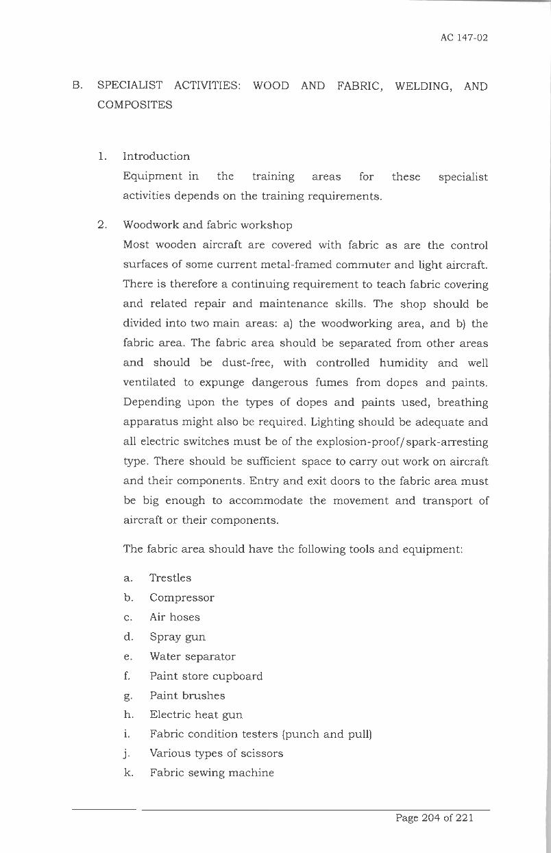
AC 147-02
B. SPECIALIST ACTIVITIES: WOOD AND FABRIC, WELDING, AND
COMPOSITES
1. Introduction
Equipment in the training areas for these specialist
activities depends on the training requirements.
2. Woodwork and fabric workshop
Most wooden aircraft are covered with fabric as are the control
surfaces of some current metal-framed commuter and light aircraft.
There is therefore a continuing requirement to teach fabric covering
and related repair and maintenance skills. The shop should be
divided into two main areas: a) the woodworking area, and b) the
fabric area. The fabric area should be separated from other areas
and should be dust-free, with controlled humidity and well
ventilated to expunge dangerous fumes from dopes and paints.
Depending upon the types of dopes and paints used, breathing
apparatus might also be required. Lighting should be adequate and
all electric switches must be of the explosion-proof/ spark-arresting
type. There should be sufficient space to carry out work on aircraft
and their components. Entry and exit doors to the fabric area must
be big enough to accommodate the movement and transport of
aircraft or their components.
The fabric area should have the following tools and equipment:
a. Trestles
b. Compressor
c. Air hoses
d. Spray gun
e. Water separator
f. Paint store cupboard
g- Paint brushes
h. Electric heat gun
i. Fabric condition testers (punch and pull)
j- Various types of scissors
k. Fabric sewing machine
Page 204 of 221

AC 147-02
The woodwork workshop should be equipped with carpenters'
benches and with a carpenter's vice at each workstation. It should
have the following combination of powered tools:
a. one carpenter's lathe
b. one wood planer
c. one circular saw
d. one disc sander
The following tools should be issued to form part of the students'
personal basic tool kits or be made available to them from the
woodwork workshop:
a. 50-cm panel saw
b. 2 5-cm dovetail saw
c. 30-cm pad saw
d. metal jack plane
e. 20-cm smoothing plane
f. one wood type spokes have
g. two Firmer chisels (6 mm and 20 mm)
h. one 12-mm sash-mortise chisel
i. one claw hammer (600 to 700 g)
j. one 150-g pattern maker's hammer
k. one carpenter's try square
1. one adjustable bevel
m. one marking gauge
n. one 1-m long folding rule
o. one ratchet brace and a selection of bits and
countersinks
p. one bradawl
q. one 30-cm cabinet pattern screwdriver
r. one 20-cm ratchet screwdriver
s. one mallet
t. one carpenter's toolbox with lock and key
Page 205 of 221

AC 147-02
3. Welding
The purpose of a short course on welding is to impart enough
knowledge of welding techniques to enable students to assess the
airworthiness of welded joints and structures. It is not intended to
produce skilled welders. The welding shop must be chosen and
equipped to comply with the safety regulations for oxyacetylene and
other types of welding. Metal-screened working bays with metal
workbenches should be built according to the number of
workstations required.
Welding equipment might include the following:
a. Set of oxyacetylene welding equipment
b. Electric arc welder
c. Electric TIG or MIG welder
d. Eye and face shields, goggles, leather gloves and aprons
e. Electrodes, welding rods and welding fluxes
f. Electric resistance welder for spot welding (may be stored in
sheet metal shop)
4. Fibreglass and reinforced plastics workshop
Many aircraft are fitted with secondary structures
constructed from fibre or glass materials. (Indeed, some
aircraft even have their primary structures made of fibre or glass
materials.) From the training point of view, only secondary
structures should be of concern. The repair of structures is a
complex and specialized operation that requires expertise often
available only from the aircraft manufacturer.
As far as space, a dust-free, humidity- controlled
atmosphere, lighting and doors are concerned, the workshop
should follow the general pattern of the fabric shop. Fireproof
storage facilities for highly inflam- mable and corrosive resins and
activators are also required. The correct type of extinguishers
must also be available. The following tools should be provided for
the fibreglass and reinforced plastics workshop:
a. Laying-up tables
b. Brushes and spatulas
Page 206 of 221

c. Scissors and cutters
d. Sanders
e. Measuring cups
f. Heat lamps
g. Pots and trays
AC 147-02
Page 207 of 221

AC 147-02
C. PRACTICAL MAINTENANCE SKILLS: ENGINE AND PROPELLER —
FACILITIES, TOOLS AND EQUIPMENT
1. INTRODUCTION
This appendix provides guidance for the kind of facilities, tools and
equipment that are likely to be needed to meet the Training
Objectives of Part E, Appendix 1 this advisory circular.
2. METALWORK AND SHEET METALWORK WITH HAND TOOLS
For basic skills training, the training workshop should be equipped
with sturdy benches mounted with vices at approximately 2-m
intervals, one vice per student. Other items required include:
a) powered grinding wheel for tool sharpening
b) powered drilling machine
c) large surface table for precision marking-off
d) compressor air supply suitable for use with
pneumatic hand tools
e) powered hacksaw for cutting stock material
f) sheet metal guillotine
g) chalkboard/whiteboard for workshop instruction and work
schedule
For engine skills training, the workshop should ideally include the
following:
a) Sectioned engines (piston or turbine, according to the needs
of the company or State), mounted and rotatable for
demonstration purposes
b) Solvent washing plant for cleaning parts
c) Mobile lifting gantry for hoisting engines and heavy
equipment
d) Engine slings and work stands for each type of engine in
the shop
e) Manufacturer's tool kits for each type of engine (including
extractors, assembly jigs, etc.) used for the complete
dismantling of engines
Page 208 of 221

AC 147-02
f) Electromagnetic (magnetic particle) crack detection equipment
g) Medium-sized surface table with vee-blocks, DTI stand, etc.
h) Propeller assembly bench with tools for measuring blade
torque
i) Propeller manufacturer's tool kit for each type of propeller
used
j) Example of contemporary propeller controllers
k) Example of various types of magnetos
1) Example of various high-energy and other types of gas turbine
igniter
m) Example of various types of carburetor and petrol injection
equipment
n) Example of turbocharger
Personal tool kit Students should have their own tools and a
toolbox. This may be issued on a shop basis, i.e. a kit issued in the
basic metalwork shop may contain only tools required for training
in this shop and be retained by the shop when the students
progress to the next phase, or students may be issued, and retain
on a permanent basis, a personal basic kit which is their own
property until com- pletion of their training. Some schools may
require students to purchase their own tools, their kits becoming
more com- plete as their training advances. The following items are
suggested for basic metalwork, airframe or engine tool kit:
a) Measuring and marking-off tools
30-cm long steel rule, graduated in fractions of
inches and millimeters
Outside and inside calipers
Try square
Set of feeler gauges
15-cm dividers
Scriber
b) Fitter's tools
- Round-nose and side-cutter pliers
- 15-cm long screwdriver
- Hacksaw
Page 209 of 221

AC 147-02
- Selection of files of different sections, lengths and cuts
- Hand drill and a set of small diameter drills
- Set of center and pin punches
- Ball-peen and cross-pane hammers
- 20-cm flat chisel and a set of small chisels
(including flat, cross-cut and round-nose)
- Plastic or hide-faced hammer
- Sheet metal snips
- Various sizes and types of screwdrivers
- Set of double-ended, open-ended and ring spanners of
appropriate range in sizes and appropriate type
(American, BSF, Unified or Metric) to suit available
airframes
- Set of socket wrenches with handles and accessories to
suit available airframes
3. ENGINE FAMILIARIZATION WORKSHOP
The supply or provision of engines in the airframe workshop is
determined according to the requirements of the technicians
undergoing training (e.g. piston or turbine engines). In general it is
desirable that licensed Aircraft Maintenance
(Technician/Engineer/Mechanic) (AME) students should have the
opportunity to remove and replace major components. Practice in
inspection functions during simulated repair or maintenance
activities is considered an important training element in this phase.
The requirements for the training of licensed AMEs are as follows:
a) Ideally, a complete engine piston and/or turbine
b) Engine test bed or airframe on which the engine can be
operated
c) Mobile lifting equipment (i.e. small crane or over- head gantry
lifting slings) and tools suitable for engine types provided
d) Desk for manuals and notices
e) Display board for inspection work sheets
f) Access and storage equipment such as benches, trestles,
shelves, etc.
g) Oil and fuel replenishing bowsers
Page 210 of 221
AC 147-02
h) Test boards designed to represent sections of typical
aircraft/engine cable, air and fluid systems. These should be
complete with rigging instructions so that student errors are
detected immediately.
Page 211 of 221

AC 147-02
D. PRACTICAL MAINTENANCE SKILLS: AVIONICS — ELECTRICAL,
INSTRUMENT, AUTOFLIGHT AND RADIO — FACILITIES, TOOLS AND
EQUIPMENT
1. INTRODUCTION
This appendix provides guidance for the kind of facilities, tools and
equipment that are likely to be needed to meet the Training
Objectives of Part F, Appendix 1 this advisor circular.
2. AVIONICS WORKSHOP: ELECTRICAL
Shop equipment. The electrical workshop should be equipped with
demonstration mock-ups representing typical aircraft circuits. If
made realistically, these can be of value for practicing adjustments
and troubleshooting as well as for demonstration. All areas of the
engine shop should have adequate benches, racks, shelves and
storage bins; electric power points and piped compressed air to
operate powered hand tools; factory safety precautions with fire
warning and extinguishing provisions. Benches should be smooth-
topped and have sufficient vices and power points (for soldering
irons) to suit the class size planned. The following major equipment
items should also be available:
a) workshop test unit for testing electrical machines (universal
types are available for testing a wide variety of generators
and motors)
b) appropriate special tools and test meters (necessary because
of the considerable range and variety of electrical equipmenton the modern aircraft)
c) Battery charging plant, preferably housed in a separate, well-
ventilated charging room. For lead acid batteries, the charging
plant should be of the series type suitable for charging several
batteries at different rates.
Page 212 of 221

AC 147-02
Note.— For charging lead acid and nickel cadmium batteries, a
separate and totally isolated charging room and equipment will be
required for each type. For nickel cadmium batteries, a constant
current charger and battery analyzer must be specified.
Personal tool kit. Students should have their own tools and a
toolbox. This may be issued on a shop basis, i.e. a kit issued in the
electrical shop may contain only tools required for training in this
shop and be retained by the shop when the students' progress to
the next phase, or students may be issued, and retain on a
permanent basis, a personal basic kit which is their own property
until the completion of their training. Some schools may require
students to purchase their own tools, their kits becoming more
complete as their training advances. The following items are
suggested for basic electrical work:
a) One electric 5-mm point temperature-controlled soldering iron
(soldering copper)
b) One wire stripper for removing insulation
c) aselectionof small screwdrivers (including a Phillips)
d) One adjustable hook wrench (18 to 50 mm)
e) One set of Allen keys
The exercises with components should be designed to develop skills
in dismantling, inspection, decision-making and assembly. The
following types of components should be available and used as
appropriate according to the potential needs of the trainees:
a) Lengths of aircraft cabling with typical plugs, sockets,
bulkhead sealing bungs, grommets, etc. for practicing wire
work and making up looms
b) A selection of switches, fuses, thermal circuit breakers, wire
connecting devices, junction boxes and other electrical system
elements
c) Specimens of airborne batteries (both lead acid and nickel
cadmium): sectioned, serviceable and chargeable
d) DC generators and AC alternators (constant speed drives)
Page 213 of 221

AC 147-02
e) Voltage regulators, generator control unit (GCU), and other
types of current limiting devices (i.e. vibrator types and
variable-resistance types)
f) Various types of DC and AC motors, including engine
starters, continuously rated motors, rotary and linear
actuators
g) Static and rotary inverters and specimens of other types of
current conversion devices, such as transformer rectifier units
(TRUs)
h) Specimens of various types of airborne electrical instruments,
including instruments embodying principles of the voltmeter,
ammeter, ohmmeter, Wheatstone bridge, thermocouple, ratio
meter, servos and synchro's, etc.
i) Specimens of aircraft electric heating devices, such as pitot
heads, thermal de-icing shoes, etc.
j) Specimens of aircraft lighting appliances, such as cabin
fluorescent lamps, landing lamps, navigation lights, etc.
3. AVIONICS WORKSHOP: INSTRUMENT
Workshop equipment. This shop should be a "clean a r e a," i. e. It
should be protected from dust, workshop fumes and industrial
contaminants. Ideally, a separate building or room with filtered
ventilation is desirable and in very humid climates, air conditioning
is essential. Benches should be topped with smooth hardwood or
covered with a Formica top. If air conditioning is not installed, it
may be necessary to provide sealed cabinets with silica gel (for
air drying) for storage of some of the test equipment and
instrument specimens.
The instrument workshop should be equipped with demonstration
mock-ups representing typical aircraft circuits. If made
realistically, these can be of value for practicing adjustments and
troubleshooting as well as for demonstration. Benches should be
smooth-topped and have
Page 214 of 221

AC 147-02
Sufficient vices and power points (for soldering irons) to suit the
class size planned. The following major equipment items should
also be available:
a) Dead weight tester for pressure gauges
b) Altimeter test chamber with substandard instrument
c) Mock-up of air speed indicator (ASI) system for leak test
practice
d) Gyroscopic instrument test table
e) Mock-up for compass swinging practice (i.e. an old aircraft or
a specially-made trolley which can be used on an outdoor site
selected as compass base)
f) Bridge Megger for insulation testing of electrical items
The personal basic tool kits of students should be supplemented by
the following items:
a) one set of watchmaker's screwdrivers
b) one set of miniature spanners
c) one set of Allen keys (appropriately sized)
d) one set of Bristol spline keys
e) one electric temperature-controlled soldering iron with fine
point (similar to that issued in the electrical workshop)
The exercises with components should be designed to
develop skills in dismantling, inspection, decision-making and
assembly. The following types of components should be available
and used as appropriate according to the potential needs of the
trainees:
a) Boost or manifold pressure gauge
b) Hydraulic pressure gauge
c) Engine oil pressure gauge (Bourdon tube type)
d) Engine oil pressure gauge (electrical type)
e) ASI
f) Pitot static head
g) Altimeter (simple and sensitive types)
Page 215 of 221

AC 147-02
i) Rate-of-climb indicatorTurn and slip indicator (air-driven
and electrical types)
j) Directional gyroscope (air-driven and electrical types)
k) Artificial horizon (air-driven and electrical types)
1) Engine speed indicator (DC and AC types)
m) Oil thermometer (physical and electrical types)
n) Cylinder head or jet-pipe thermocouple
0) Fuel content gauge (float-operated and capacitance types)
p) Magnetic compass
q) Simple type of autopilot
4. AVIONICS WORKSHOP: AUTOFLIGHT, NAVIGATION AND RADIO
Workshop equipment. This shop should be a "clean area," i. e. It
should b e protected f r o m dust, workshop fumes and industrial
contaminants. The shop could be combined with the instrument
workshop. Ideally, a separate building or room with filtered
ventilation is desirable and in very humid climates, air conditioning
is essential. Benches should be topped with smooth hardwood or
covered with a Formica top. If air conditioning is not installed, it
may be necessary to provide sealed cabinets with silica gel (for
air drying) for storage of some of the test equipment and
instrument specimens.
The following test equipment items should also be available:
a) Variable stabilized power supply unit
b) Signal generator (high grade)
c) Signal generators for bench
d) Signal generator (UHFNHF)
e) Audio-frequency oscillators
f) Spectrum analyzer
g) Cathode ray oscilloscopes
h) Frequency meters
i) Moving coil, volt-ohm-milliamp ere, and mustimeters j) Varian
k) Digital analyzer
1) Valve and transistor characteristics tester
m) Digital voltmeter/ohmmeter/ammeter
Page 216 of 221

AC 147-02
n) Logic probe
0) R, L, C bridge
p) Voltage standing wave meters
q) Absorption and thermocouple watt meter
The workshop should be equipped with demonstration mock-ups
representing typical aircraft circuits. The following equipment may
be of value for practicing adjustments and troubleshooting as well
as for demonstration:
a) High frequency (HF) transmitter/receiver
b) Very high frequency (VHF) transmitter/receiver
c) Automatic direction finder system
d) VHF omnidirectional radio range/instrument landing system
(VOR/ILS) system (including glideslope and marker receivers)
e) Distance measuring equipment system
f) Air traffic control transponder system (including altitude
reporting mode)
g) Radio altimeter
h) Weather radar
i) Very Low Frequency (VLF) Omega navigation system
j) Loran-C system
k) Doppler navigation system
1) Navigation indicators capable of presenting combined
navigation information, typically a radio magnetic indicator
(RMI) and horizontal situation indicator (HSI) wired for both
compass and various radio navigation input
m) Instrument systems with electronic amplifiers (e.g.
capacitance type fuel contents gauges, cabin temperature
controllers, and automatic pilots)
Page 217 of 221

AC 147-02
The radio section of the workshop needs a screened room or "cage"
to prevent undue radiation from equipment undergoing testing and
to provide an interference-free region for fine measurement.
Although it is desirable to have this room adjoining the radio
workshop, they should not be close to sources of interference, such
as an electrical overhaul shop or spark plug testing equipment. As
a further safeguard against interference, all power supplies to the
radio workshop should be filtered, and outgoing interference
should be suppressed by adequate screening of aerial cables and
artificial aerials. Alternatively, if a screened room is unavailable,
for certain types of equipment, it is possible to use a field
simulator specified by the equipment manufacturer. (A metal box
in which the respective antenna is placed to eliminate unwanted
radiations a n d interference.) The following power supplies will
be required:
a) AC mains supply for lighting, heating, air conditioning, mains
rectifiers, test instruments, soldering irons, etc. (This will be
at the standard voltage of the locality and the supply should
be wired throughout in screened conduit.)
b) 30-volt DC supply, surge-free and of adequate capacity for the
size of the workshop. (A ring main supply from lead acid or
alkaline cells, ripple-free and filtered is suitable or a mains
rectifier/regulator can be used.)
c) 15-volt DC supply, also surge-free
d) 115-volt, 400-cycle, single-phase AC supply. (This should be
frequency-monitored and can be taken from a static inverter.)
e) 115-volt, 400-cycle, three-phase AC supply, frequency-
monitored and wired to the working benches by screened
cable
f) 26-volt, 400-cycle, single-phase AC supply, taken from the
115-volt AC supply through a transformer or from the 26-volt
AC output from the static inverter
g) Compressed air and vacuum supplies
Page 218 of 221

AC 147-02
The personal basic tool kits of students should be the same as
specified for the instrument workshop but may be supplemented to
suit local needs.
The exercises with components and system demonstration rigs
should be designed with a view to developing skills in inspection
fault finding and decision- making.
DIRECTOR GENERAL OF CIVIL AVIATION
ttd
Dr. Ir. AGUS SANTOSO, M.Sc
Salinan sesuai aslinyaKEPALA BAGIAN HUKUM
;ndah purnama sari
Pembina/(IV/a)NIP. 19680704 199503 2 00
Page 219 of 220
:.