base station antennas1
DESCRIPTION
Base Station AntennasTRANSCRIPT

Allgon Antenna Systems
Future on Demand.
NMT 900, ETACS 900, GSM 900, DCS 1800
TAB
LE OF C
ON
TEN
TS
TABLE OF CONTENTS
Table of Contents Page 3
What’s Inside
Allgon 1800 MHz Metro Panel Antennas (M)Overview Page 4Quick Reference Guide Page 533 Degree Beamwidth Page 665 Degree Beamwidth Page 790 Degree Beamwidth Page 9
Allgon Dual Polarized Antennas (XM,XU)Overview Page 11Quick Reference Guide Page 1265 Degree Beamwidth 1800 MHz Dual Polarized Page 1390 Degree Beamwidth 1800 MHz Dual Polarized Page 1565 Degree Beamwidth 900 MHz Dual Polarized Page 16
Allgon 900 MHz Log Periodic (A)Overview Page 19Quick Reference Guide Page 2035 Degree Beamwidth Page 21
Allgon 900 MHz City Panel Antennas (CI)Overview Page 22Quick Reference Guide Page 2360 Degree Beamwidth Page 2490 Degree Beamwidth Page 26105 Degree Beamwidth Page 28120 Degree Beamwidth Page 29
Allgon 900 MHz Adjustable ElectricalDowntilt Panel Antennas (CI-A)Overview Page 31Quick Reference Guide Page 3260 Degree Beamwidth Page 3390 Degree Beamwidth Page 33105 Degree Beamwidth Page 34120 Degree Beamwidth Page 34
Allgon 900 MHz Urban Panel Antennas (U)Overview Page 35Quick Reference Guide Page 3665 Degree Beamwidth Page 3790 Degree Beamwidth Page 39
Allgon Omnidirectional Antennas (O)Overview Page 41Quick Reference Guide Page 42900 MHz Omni Page 43
Allgon Indoor Antennas (CO, ALIC)Overview Page 44Quick Reference Guide Page 45900 MHz Panel Antenna Page 46Multi-band Omni Page 46
Allgon Dualband Solution (ALXC)Overview Page 48Quick Reference Guide Page 4965 Degree Beamwidth Page 50900/1800 MHz Dualband Filter Page 52
Mounting Brackets Page 53Testing Procedures Page 54
Tower Top AmplifierOverview Page 55Quick Reference Guide Page 56Tower Top Amplifiers Page 57
Tower Top Power AmplifierOverview Page 59Quick Reference Guide Page 60Tower Top Amplifiers Page 61
We also have a wide range of 800 and 1900 MHzantennas. For more information, see our websiteat www.allgon.com.
Digital pattern information for Allgon antennascan be obtained from www.allgon.com.

1800 MH
z Metro
Panel Antenna
1800 MHz Metro Panel Antenna
Features
• High pattern stability over entire frequency band• Superior vertical pattern shaping for interference
reduction• 100% verified for vertical pattern performance• Mechanical design allows for thermal expansion• Aesthetically pleasing
Design Philosophy
Quality Materials
Our Metro panel antenna is designed andmanufactured by a repeatable procedure, whichallows the product to pass stringent electricaltesting in production in its “as built” configuration.The 1800 MHz panel antenna has a robust me-chanical design, which does not rely on the radomefor support. The radome, which is only used forweatherproofing, is set inside the endcaps andallows for thermal expansion.
Proper use of materials and their structure ensuresperformance integrity. In antennas the electrical per-formance is directly related to mechanical performance.The choice of radome material is crucial since it actsas a window between the radiating elements and thecoverage area. Our UV stabilized PVC radome isresistant to moisture absorption. Furthermore, ourradomes can withstand mechanical stresses, even atlow temperatures and long exposure to UV radiation.For corrosion inhibition, we use aircraft quality alumi-num alloy that is inherently resistant to corrosioncaused by the environment.
The Allgon 1800 MHz panel antennas haveverified vertical pattern performance on 100% ofthe antennas. Given the narrow mechanicalwidth and depth of the product, the offerings areunmatched in Front-to-Back Ratio for all openingangles. The 1800 MHz panel antenna hasconsistent reliable performance from frequencyto frequency and product to product.
Performance
Bracket hardware for the 1800 MHz panel antennais made of only the highest quality aircraftaluminum and galvanized or stainless steel, and isavailable in non-tilt and mechanical tilt for mountingto a pipe. The 1800 MHz panel antenna can also beflush mounted with tilt or panning. For more infor-mation, please see page 53.
Brackets
Base Station Antennas Page 4
Allgon prides itself on stringent testing require-ments with conservative, yet realistic claims ofthe performance of our product offering. Formore information on testing procedures, seepage 54. Our front-to-back ratios are specifiedfor ±20° from 180° (worst case) to 0°.
Testing
Upper & Lower Placement7/16 DIN Connector
Connectors
Base Station Antennas Page 5
1800
MH
z M
etro
Pan
el A
nten
naQUICK REFERENCE GUIDE
90 Degree 1800 MHz Panel
Gain Part Number Description Page13.5 dBi
15.5 dBi
16.5 dBi
17.5 dBi
7194.01 M-1800-90-13.5i-6-D 9
7198.01 M-1800-90-15.5i-2-D 9
7184.01 M-1800-90-16.5i-2-D 10
7187.01 M-1800-90-17.5i-2-D 107187.02 M-1800-90-17.5i-2-D-U 107187.03 M-1800-90-17.5i-4-D 107187.04 M-1800-90-17.5i-4-D-U 10
65 Degree 1800 MHz Panel
Gain Part Number Description Page
12.5 dBi
15 dBi
17 dBi
18 dBi
17.5 dBi
7205.01 M-1800-65-12.5i-0-D 77205.02 M-1800-65-12.5i-0-D-U 7
7195.05 M-1800-65-15i-2-D 77195.01 M-1800-65-15i-6-D 77195.02 M-1800-65-15i-6-D-U 7
7183.01 M-1800-65-17i-2-D 8
7182.10 M-1800-65-18i-0-D 87182.11 M-1800-65-18i-0-D-U 87182.01 M-1800-65-18i-2-D 87182.02 M-1800-65-18i-2-D-U 8
7182.05 M-1800-65-17.5i-6-D 87182.06 M-1800-65-17.5i-6-D-U 8
33 Degree 1800 MHz Panel
Gain Part Number Description Page
19.5 dBi7185.01 M-1800-33-19.5i-2-D 67185.02 M-1800-33-19.5i-2-D-U 6
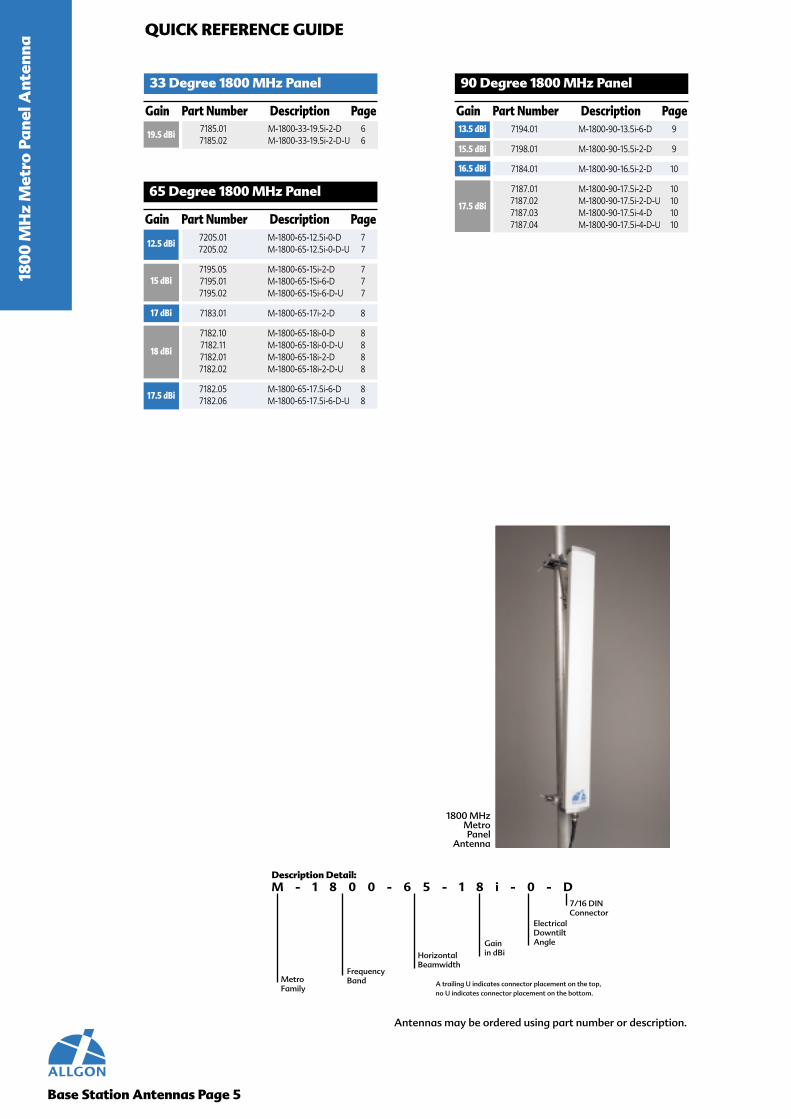
1800 MHzMetroPanel
Antenna
M - 1 8 0 0 - 6 5 - 1 8 i - 0 - D7/16 DINConnector
Description Detail:
MetroFamily
FrequencyBand
HorizontalBeamwidth
Electrical DowntiltAngleGain
in dBi
A trailing U indicates connector placement on the top, no U indicates connector placement on the bottom.
Antennas may be ordered using part number or description.

M-1800-33-19.5i
Electrical Specifications 7185(M-1800-33-19.5i)
Base Station Antennas Page 6
1800 MHz Metro Panel Antenna
Gain 19.5 dBi (17.5 dBd)Polarization linear, verticalVSWR, 50Ω <1.3:1 (1710 MHz to 1880 MHz)
Horizontal 3dB beamwidth 33°Vertical 3dB beamwidth 9°Custom electrical downtilts 2°
40 degree cone Front-to-back ratio >30 dBSuppression of first upper side lobe >14 dBFirst lower null fill >-23 dB
Maximum CW input power 200WTwo tone intermodulation 3rd order <-103 dBm for 2x10W
(143 dBc at 2x40 dBm)
A poster displaying a comparison of antenna patterns has been included at the back of the catalog.
Mechanical Specifications
Connector 7/16 DIN bottom or top mountHeight 1000 mm (39.4")Width 265 mm (10.4")Depth 43 mm (1.7")
Weight 5 kg (11 lb)Survival wind speed 70 m/s (156 mph)Maximum wind area 0.27 sq.m (2.9 sq ft)Frontal wind load @ 150 km/h (C=1) 290 N (65.2 lbf)
*All metallic components DC grounded for Lightning Protection
Mounting Hardware Options for Installation1) Pole mount 2165.102) Combined pole mount/downtilt bracket 7254.10 (-1° to +22°)
CommentsGain is typical within frequency band.Front-to-back ratio is defined within 20° from the backwards direction in any plane.Sidelobe suppression and null fill is relative to peak of main beam.Radome color is NCS 2502-B (RAL 7035)(gray).
For a complete list of released models pertaining to gain, electrical downtilt and connector placement,
please see the quick reference guide on page 5.
1800 MH
z Metro
Panel Antenna
Typical Horizontal and Vertical 7185.01 Patterns

Electrical Specifications 7205 7195(M-1800-65-12.5i) (M-1800-65-15i)
Base Station Antennas Page 7
1800 MHz Metro Panel Antenna
Gain 12.5 dBi (10.5 dBd) 15 dBi (13 dBd)Polarization linear, vertical linear, verticalVSWR, 50Ω <1.3:1 (1710 MHz to 1880 MHz) <1.3:1 (1710 MHz to 1880 MHz)
Horizontal 3dB beamwidth 65° 65°Vertical 3dB beamwidth 26° 15°Custom electrical downtilts 0° 2° & 6°
40 degree cone Front-to-back ratio >25 dB >26 dBSuppression of first upper side lobe N/A >14 dBFirst lower null fill N/A >-20 dB
Maximum CW input power 200W 200WTwo tone intermodulation 3rd order <-103 dBm for 2x10W <-103 dBm for 2x10W
(143 dBc at 2x40 dBm) (143 dBc at 2x40 dBm)
A poster displaying a comparison of antenna patterns has been included at the back of the catalog.
Mechanical Specifications
Connector 7/16 DIN top or bottom mount 7/16 DIN top or bottom mountHeight 380 mm (15") 660 mm (26")Width 136 mm (5.4") 136 mm (5.4")Depth 50 mm (2") 50 mm (2")
Weight 1.4 kg (3.1 lb) 2.6 kg (5.7 lb)Survival wind speed 70 m/s (156 mph) 70 m/s (156 mph)Maximum wind area 0.05 sq.m (0.56 sq ft) 0.09 sq.m (0.97 sq ft)Frontal wind load @150 km/h (C=1) 60 N (13.5 lbf) 100 N (22.5 lbf)
*All metallic components DC grounded for Lightning Protection
Mounting Hardware Options for Installation1) Pole mount 2165.10 2165.102) Combined pole mount/downtilt bracket 7254.10 (-2.7° to +71°) 7254.10 (-1.3° to +33°)
CommentsGain is typical within frequency band.Front-to-back ratio is defined within 20° from the backwards direction in any plane.Sidelobe suppression and null fill is relative to peak of main beam.Radome color is NCS 2502-B (RAL 7035)(gray).
For a complete list of released models pertaining to gain, electrical downtilt and connector placement,
please see the quick reference guide on page 5.
1800
MH
z M
etro
Pan
el A
nten
naM
-180
0-65
-15i
Typical Horizontal and Vertical 7205.01 Patterns Typical Horizontal and Vertical 7195.05 Patterns
M-1
800-
65-1
2.5i

Base Station Antennas Page 8
Electrical Specifications 7183 7182(M-1800-65-17i) (M-1800-65-18i)
1800 MHz Metro Panel Antenna
Gain 17 dBi (15 dBd) 18 dBi (16 dBd)Polarization linear, vertical linear, verticalVSWR, 50Ω <1.3:1 (1710 MHz to 1880 MHz) <1.3:1 (1710 MHz to 1880 MHz)
Horizontal 3dB beamwidth 65° 65°Vertical 3dB beamwidth 9° 7°Custom electrical downtilts 2° 0°, 2 & 6°
40 degree cone Front-to-back ratio >27 dB >27 dBSuppression of first upper side lobe >15 dB >16 dBFirst lower null fill >-23 dB >-23 dB
Maximum CW input power 200W 200WTwo tone intermodulation 3rd order < -103 dBm for 2x10W < -103 dBm for 2x10W
(143 dBc at 2x40 dBm) (143 dBc at 2x40 dBm)
A poster displaying a comparison of antenna patterns has been included at the back of the catalog.
Mechanical Specifications
Connector 7/16 DIN bottom mount 7/16 DIN bottom or top mountHeight 1000 mm (39.4") 1300 mm (51.3")Width 136 mm (5.4") 136 mm (5.4")Depth 50 mm (2") 50 mm (2")
Weight 3.6 kg (8 lb) 4.4 kg (9.7 lb)Survival wind speed 70 m/s (156 mph) 70 m/s (156 mph)Maximum wind area 0.14 sq.m (1.5 sq ft) 0.18 sq.m (1.9 sq ft)Frontal wind load @150 km/h (C=1) 150 N (33.7 lbf) 190 N (42.7 lbf)
*All metallic components DC grounded for Lightning Protection
Mounting Hardware Options for Installation1) Pole mount 2165.10 2165.102) Combined pole mount/downtilt bracket 7254.10 (-1° to +22°) 7254.10 (-0.7° to +16°)
CommentsGain is typical within frequency band.Front-to-back ratio is defined within 20° from the backwards direction in any plane.Sidelobe suppression and null fill is relative to peak of main beam.Radome color is NCS 2502-B (RAL 7035)(gray).
For a complete list of released models pertaining to gain, electrical downtilt and connector placement,
please see the quick reference guide on page 5.
M-1800-65-17i
1800 MH
z Metro
Panel Antenna
M-1800-65-18i
Typical Horizontal and Vertical 7183.01 Patterns Typical Horizontal and Vertical 7182.10 Patterns

Electrical Specifications 7194 7198(M-1800-90-13.5i) (M-1800-90-15.5i)
Base Station Antennas Page 9
1800 MHz Metro Panel Antenna
Gain 13.5 dBi (11.5 dBd) 15.5 dBi (13.5 dBd)Polarization linear, vertical linear, verticalVSWR, 50Ω <1.3:1 (1710 MHz to 1880 MHz) <1.3:1 (1710 MHz to 1880 MHz)
Horizontal 3dB beamwidth 90° 90°Vertical 3dB beamwidth 15° 9°Custom electrical downtilts 6° 2°
40 degree cone Front-to-back ratio >23 dB >25 dBSuppression of first upper side lobe >14 dB >15 dBFirst lower null fill >-23 dB >-23 dB
Maximum CW input power 200W 200WTwo tone intermodulation 3rd order <-103 dBm for 2x10W <-103 dBm for 2x10W
(143 dBc at 2x40 dBm) (143 dBc at 2x40 dBm)
A poster displaying a comparison of antenna patterns has been included at the back of the catalog.
Mechanical Specifications
Connector 7/16 DIN bottom mount 7/16 DIN bottom mountHeight 660 mm (26") 1000 mm (39.4")Width 136 mm (5.4") 136 mm (5.4")Depth 50 mm (2") 50 mm (2")
Weight 2.6 kg (5.7 lb) 3.6 kg (7.9 lb)Survival wind speed 70 m/s (156 mph) 70 m/s (156 mph)Maximum wind area 0.9 sq.m (0.97 sq ft) 0.14 sq.m (1.5 sq ft)Frontal wind load @150 km/h (C=1) 100 N (22.5 lbf) 150 N (33.7 lbf)
*All metallic components DC grounded for Lightning Protection
Mounting Hardware Options for Installation1) Pole mount 2165.10 2165.102) Combined pole mount/downtilt bracket 7254.10 (-1.3° to +33°) 7254.10 (-1° to +22°)
CommentsGain is typical within frequency band.Front-to-back ratio is defined within 20° from the backwards direction in any plane.Sidelobe suppression and null fill is relative to peak of main beam.Radome color is NCS 2502-B (RAL 7035)(gray).
For a complete list of released models pertaining to gain, electrical downtilt and connector placement,
please see the quick reference guide on page 5.
M-1
800-
90-1
3.5i
1800
MH
z M
etro
Pan
el A
nten
naM
-180
0-90
-15.
5i
Typical Horizontal and Vertical 7194.01 Patterns Typical Horizontal and Vertical 7198.01 Patterns

Electrical Specifications 7184 7187(M-1800-90-16.5i) (M-1800-90-17.5i)
Base Station Antennas Page 10
1800 MHz Metro Panel Antenna
Gain 16.5 dBi (14.5 dBd) 17.5 dBi (15.5 dBd)Polarization linear, vertical linear, verticalVSWR, 50Ω <1.3:1 (1710 MHz to 1880 MHz) <1.3:1 (1710 MHz to 1880 MHz)
Horizontal 3dB beamwidth 90° 90°Vertical 3dB beamwidth 7° 5°Custom electrical downtilts 2° 2° & 4°
40 degree cone Front-to-back ratio >25 dB >25 dBSuppression of first upper side lobe >16 dB >17 dBFirst lower null fill >-23 dB >-18 dB
Maximum CW input power 200W 200WTwo tone intermodulation 3rd order <-103 dBm for 2x10W <-103 dBm for 2x10W
(143 dBc at 2x40 dBm) (143 dBc at 2x40 dBm)
A poster displaying a comparison of antenna patterns has been included at the back of the catalog.
Mechanical Specifications
Connector 7/16 DIN bottom mount 7/16 DIN bottom or top mountHeight 1300 mm (51.2") 1900 mm (74.8")Width 136 mm (5.4") 136 mm (5.4")Depth 50 mm (2") 50 mm (2")
Weight 4.4 kg (9.7 lb) 5.8 kg (12.8 lb)Survival wind speed 70 m/s (156 mph) 70 m/s (156 mph)Maximum wind area 0.18 sq.m (1.9 sq ft) 0.26 sq.m (2.8 sq ft)Frontal wind load @150 km/h (C=1) 190 N (42.7 lbf) 280 N (62.9 lbf)
*All metallic components DC grounded for Lightning Protection
Mounting Hardware Options for Installation1) Pole mount 2165.10 2165.112) Combined pole mount/downtilt bracket 7254.10 (-0.7° to +16°) 7254.11 (-0.5° to +11°)
CommentsGain is typical within frequency band.Front-to-back ratio is defined within 20° from the backwards direction in any plane.Sidelobe suppression and null fill is relative to peak of main beam.Radome color is NCS 2502-B (RAL 7035)(gray).
For a complete list of released models pertaining to gain, electrical downtilt and connector placement,
please see the quick reference guide on page 5.
1800 MH
z Metro
Panel Antenna
M-1800-90-17.5i
Typical Horizontal and Vertical 7184.01 Patterns Typical Horizontal and Vertical 7187.01 Patterns
M-1800-90-16.5i

1800 & 900 M
Hz D
ual Polarized
Antenna
1800 & 900 MHz Dual Polarized Antenna
Features
• Slant 45 degree design to optimizeperformance
• Superior diversity performance due topatented element design
• High cross polar discrimination factor• High port to port isolation • Exact aperture angle• Minimum squint and tracking• Superior vertical pattern shaping for
interference reduction• 100% verified for vertical pattern
performance
Design Philosophy
The Allgon Dual Polarized antenna is designedwith a slant +45° configuration which has equalsignal strengths. Research has determined that thehorizontal/vertical configuration has large differ-ences in mean signal strength between the twobranches, because the horizontal component hasgreater propagation loss than the vertical. Our de-sign is backed by thorough research and testing toinsure the highest possible diversity gain, isolation,and cross polarization discrimination.
Proper use of materials and their structure ensureperformance integrity. In antennas, the electrical per-formance is directly related to mechanical structure.The choice of radome material is crucial since it actsas a window between the radiating elements and thecoverage area. Our UV stabilized PVC and extrudedfiberglass radomes have extremely low moistureabsorption. Further, our radomes withstand mechan-ical stresses, even at low temperatures and longexposure to UV radiation. For corrosion inhibition, weuse aircraft quality aluminum alloy that is inherentlyresistant to corrosion caused by the environment.
The Allgon Dual Polarized antenna has beendesigned and tested to ensure maximumperformance and reduced polarization errors.Isolation is another important aspect of dualpolarized antennas. A well designed antenna shouldhave at least 30 dB - it is a sign of quality and showshow much effort has been put into the design stage.
Performance
Bracket hardware for the Allgon Dual Polarizedantennas is made of only the highest quality aircraftaluminum and galvanized or stainless steel, and isavailable in non-tilt and mechanical tilt for mountingto a pipe. The 900 & 1800 MHz Dual Polarizedantennas can also be flush mounted with tilt or pan-ning. For more information, please see page 53.
Brackets
Quality Materials
Base Station Antennas Page 11
Allgon prides itself on stringent testing require-ments with conservative, yet realistic claims ofthe performance of our product offering. Formore information on testing procedures, seepage 54. Our front-to-back ratios are specifiedfor ±20° from 180° (worst case) to 0° in a totalpower configuration.
Testing
Connectors
7/16 DIN ConnectorType “N” Connector
Base Station Antennas Page 12
1800
& 9
00 M
Hz
Dua
l Po
lari
zed
Ant
enna
QUICK REFERENCE GUIDE
65 Degree 900 MHz Dual Polarized
Gain Part Number Description Page
12.5 dBi
16.5 dBi
14.5 dBi
17.5 dBi
15.5 dBi
17 dBi
15 dBi
18 dBi
7216.01 XU-900-65-12.5i-0-N 167216.03 XU-900-65-12.5i-0-D 16
7217.01 XU-900-65-15.5i-0-N 177217.04 XU-900-65-15.5i-0-D 17
7217.03 XU-900-65-15i-7-D 17
7217.11 XU-900-65-14.5i-9-D 17
7255.01 XU-900-65-17i-0-N 177255.04 XU-900-65-17i-0-D 17
7255.05 XU-900-65-16.5i-6-N 177255.03 XU-900-65-16.5i-6-D 17
7218.01 XU-900-65-18i-0-N 187218.05 XU-900-65-18i-0-D 18
7218.04 XU-900-65-17.5i-4-D 187218.03 XU-900-65-17.5i-6-D 18
18.5 dBi
65 Degree 1800 MHz Dual Polarized
Gain Part Number Description Page14.5 dBi 7289.02 XM-1800-65-14.5i-0-D 13
7247.03 XM-1800-65-18.5i-2-D 147247.04 XM-1800-65-18.5i-6-D 14
90 Degree 1800 MHz Dual Polarized
Gain Part Number Description Page16 dBi 7248.02 XM-1800-90-16i-0-D 15
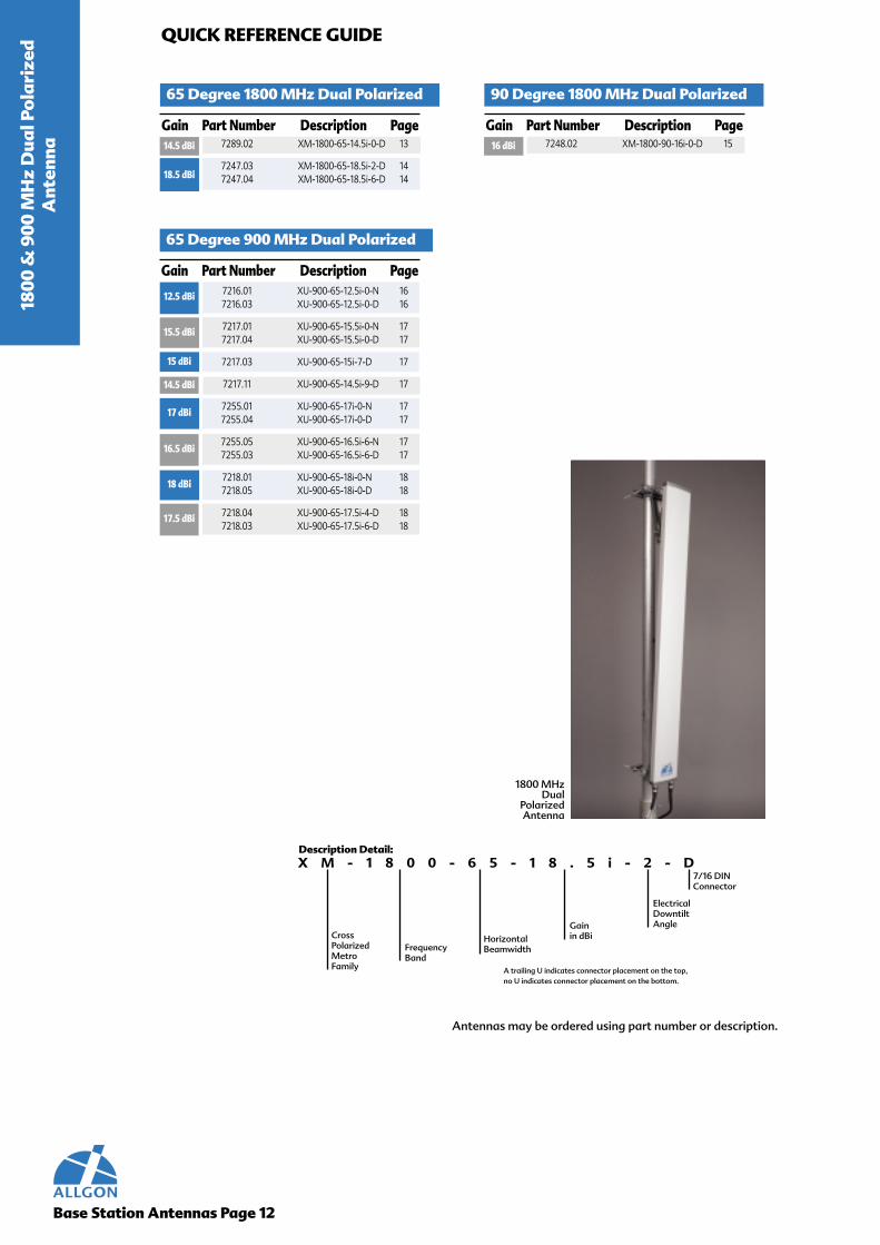
1800 MHzDual
PolarizedAntenna
X M - 1 8 0 0 - 6 5 - 1 8 . 5 i - 2 - D7/16 DINConnector
Description Detail:
CrossPolarizedMetroFamily
FrequencyBand
HorizontalBeamwidth
Electrical DowntiltAngleGain
in dBi
A trailing U indicates connector placement on the top, no U indicates connector placement on the bottom.
Antennas may be ordered using part number or description.

Electrical Specifications 7289(XM-1800-65-14.5i)
Base Station Antennas Page 13
1800 & 900 MHz Dual Polarized Antenna
Gain 14.5 dBi (12.5 dBd)Polarization linear, dual slant 45VSWR, 50Ω <1.3:1 (1710 MHz to 1880 MHz)Horizontal 3dB beamwidth 65°Vertical 3dB beamwidth 18°Custom electrical downtilts 0°40 degree cone Front-to-back ratio >23 dB co-polar, >19 dB total power Cross-polar discrimination, boresite >17 dBSuppression of first upper side lobe >14 dBFirst lower null fill N/AMaximum CW input power 500W total at 250W per inputTwo tone intermodulation 3rd order <-107 dBm for 2x10W (147 dBc at 2x40 dBm)Isolation between ports >30 dB
A poster displaying a comparison of antenna patterns has been included at the back of the catalog.
Typical Horizontal and Vertical 7289.02 Patterns
Mechanical Specifications
Connector 7/16 DIN bottom mountHeight 596 mm (23.5")Width 166 mm (6.6")Depth 55 mm (2.2")Weight 2.8 kg (6.2 lb))Survival wind speed 70 m/s (156 mph)Maximum wind area 0.10 sq.m (1.05 sq ft)Frontal wind load @150 km/h (C=1) 100 N (22.5 lbf)
*All feed network components DC grounded for Lightning Protection
Mounting Hardware Options for Installation1) Pole mount 2165.102)Combined pole mount/downtilt bracket 7254.10 (-1.5° to +35°)
CommentsGain is typical within frequency band.Beamwidths are defined using total power.Cross-polar discrimination is defined within -3 dB beamwidth.Front-to-back ratio is defined within 20° from the backwards direction in any plane.Sidelobe suppression and null fill is relative to peak of main beam.Maximum input power is total input power, divided arbitrarily between inputs.Radome color is NCS 2502-B (RAL 7035)(gray).
For a complete list of released models pertaining to gain, electrical downtilt and connector placement,
please see the quick reference guide on page 14.
XM
-1800-65-14.5i1800 &
900 MH
z Dual Po
larized
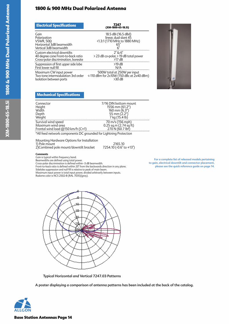
Electrical Specifications 7247(XM-1800-65-18.5i)
Base Station Antennas Page 14
1800 & 900 MHz Dual Polarized Antenna
Gain 18.5 dBi (16.5 dBd)Polarization linear, dual slant 45VSWR, 50Ω <1.3:1 (1710 MHz to 1880 MHz)Horizontal 3dB beamwidth 65°Vertical 3dB beamwidth 6°Custom electrical downtilts 2° & 6° 40 degree cone Front-to-back ratio > 23 dB co-polar, > 19 dB total powerCross-polar discrimination, boresite >17 dBSuppression of first upper side lobe >19 dBFirst lower null fill N/AMaximum CW input power 500W total at 250W per inputTwo tone intermodulation 3rd order <-110 dBm for 2x10W (150 dBc at 2x40 dBm)Isolation between ports >30 dB
A poster displaying a comparison of antenna patterns has been included at the back of the catalog.
Typical Horizontal and Vertical 7247.03 Patterns
Mechanical Specifications
Connector 7/16 DIN bottom mountHeight 1556 mm (61.2")Width 160 mm (6.3")Depth 55 mm (2.2")Weight 7 kg (15.4 lb)Survival wind speed 70 m/s (156 mph)Maximum wind area 0.25 sq.m (2.74 sq ft)Frontal wind load @150 km/h (C=1) 270 N (60.7 lbf)*All feed network components DC grounded for Lightning Protection
Mounting Hardware Options for Installation1) Pole mount 2165.102)Combined pole mount/downtilt bracket 7254.10 (-0.6° to +13°)
CommentsGain is typical within frequency band.Beamwidths are defined using total power.Cross-polar discrimination is defined within -3 dB beamwidth.Front-to-back ratio is defined within 20° from the backwards direction in any plane.Sidelobe suppression and null fill is relative to peak of main beam.Maximum input power is total input power, divided arbitrarily between inputs.Radome color is NCS 2502-B (RAL 7035)(gray).
For a complete list of released models pertaining to gain, electrical downtilt and connector placement,
please see the quick reference guide on page 14.
XM
-180
0-65
-18.
5i18
00 &
900
MH
z D
ual P
ola
rize
d A
nten
na

Base Station Antennas Page 15
1800 & 900 MHz Dual Polarized Antenna
A poster displaying a comparison of antenna patterns has been included at the back of the catalog.
Typical Horizontal and Vertical 7248.02 Patterns
1900 & 800 M
Hz D
ual Polarized A
ntennaX
M-1800-90-16i
Electrical Specifications 7248(XM-1800-90-16i)
Gain 16 dBi (14 dBd)Polarization linear, dual slant 45VSWR, 50Ω <1.3:1 (1710 MHz to 1880 MHz)Horizontal 3dB beamwidth 90°Vertical 3dB beamwidth 7.5°Custom electrical downtilts 0°40 degree cone Front-to-back ratio > 25 dB co-polar, > 20 dB total powerCross-polar discrimination, boresite >15 dBSuppression of first upper side lobe >20 dBFirst lower null fill >-18 dBMaximum CW input power 500W total at 250W per inputTwo tone intermodulation 3rd order <-110 dBm for 2x10W (150 dBc at 2x40 dBm)Isolation between ports >30 dB
Mechanical Specifications
Connector 7/16 DIN bottom mountHeight 1300 mm (51.2")Width 126 mm (5")Depth 80 mm (3.2")Weight 4.9 kg (10.8 lb)Survival wind speed 70 m/s (156 mph)Maximum wind area 0.16 sq.m (1.8 sq ft)Frontal wind load @150 km/h (C=1) 180 N (40.4 lbf)*All feed network components DC grounded for Lightning Protection
Mounting Hardware Options for Installation1) Pole mount 2165.102)Combined pole mount/downtilt bracket 7254.10 (-0.7° to +16°)
CommentsGain is typical within frequency band.Beamwidths are defined using total power.Cross-polar discrimination is defined within -3 dB beamwidth.Front-to-back ratio is defined within 20° from the backwards direction in any plane.Sidelobe suppression and null fill is relative to peak of main beam.Maximum input power is total input power, divided arbitrarily between inputs.Radome color is NCS 2502-B (RAL 7035)(gray).
For a complete list of released models pertaining to gain, electrical downtilt and connector placement,
please see the quick reference guide on page 14.

XU
-900
-65-
12.5
i
Electrical Specifications 7216(XU-900-65-12.5i)
Base Station Antennas Page 16
1800 & 900 MHz Dual Polarized Antenna
Gain 12.5 dBi (10.5 dBd)Polarization linear, dual slant 45VSWR, 50Ω <1.4:1 (880 MHz to 915 MHz)VSWR, 50Ω <1.3:1 (925 MHz to 960 MHz)Horizontal 3dB beamwidth 65°Vertical 3dB beamwidth 26°Custom electrical downtilts 0°40 degree cone Front-to-back ratio >24 dB co-polar, >20 dB total powerCross-polar discrimination, boresite >20 dBSuppression of first upper side lobe >10 dBMaximum CW input power 250WTwo tone intermodulation 3rd order< -107 dBm for 2x20W (150 dBc at 2x43 dBm)Isolation between ports >30 dB
A poster displaying a comparison of antenna patterns has been included at the back of the catalog.
Typical Horizontal and Vertical 7216.03 Patterns
Mechanical Specifications
Connector 7/16 DIN or type N bottom mountHeight 660 mm (25.9")Width 256 mm (10.1")Depth 50 mm (2")Weight 4kg (8.8 lb)Survival wind speed 55 m/s (123 mph)Maximum wind area 0.17 sq.m (1.8 sq ft)Frontal wind load @150 km/h (C=1) 190 N (42.7 lbf)*All feed network components DC grounded for Lightning Protection
Mounting Hardware Options for Installation1) Pole mount 2165.102) Combined pole mount/downtilt bracket 7254.10 (-1.5° to +35°)
CommentsGain is typical within frequency band.Beamwidths are defined using total power.Cross-polar discrimination is defined within -3 dB beamwidth.Front-to-back ratio is defined within 20° from the backwards direction in any plane.Sidelobe suppression and null fill is relative to peak of main beam.Maximum input power is total input power, divided arbitrarily between inputs.Radome color is NCS 2502-B (RAL 7035)(gray).
For a complete list of released models pertaining to gain, electrical downtilt and connector placement,
please see the quick reference guide on page 14.
1900
& 8
00 M
Hz
Dua
l Po
lari
zed
Ant
enna
Electrical Specifications 7217 7255(XU-900-65-15.5i) (XU-900-65-17i)
Base Station Antennas Page 17
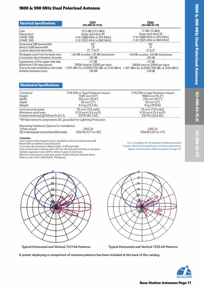
1800 & 900 MHz Dual Polarized Antenna
Gain 15.5 dBi (13.5 dBd)Polarization linear, dual slant 45VSWR, 50Ω <1.4:1 (880 MHz to 915 MHz)VSWR, 50Ω <1.3:1 (925 MHz to 960 MHz)Horizontal 3dB beamwidth 65°Vertical 3dB beamwidth 13°Custom electrical downtilts 0°, 7° & 9°40 degree cone Front-to-back ratio >24 dB co-polar, >20 dB total powerCross-polar discrimination, boresite >20 dBSuppression of first upper side lobe >17 dBMaximum CW input power 500W total at 250W per inputTwo tone intermodulation 3rd order <-107 dBm for 2x20W (150 dBc at 2x43 dBm)Isolation between ports >30 dB
A poster displaying a comparison of antenna patterns has been included at the back of the catalog.
Typical Horizontal and Vertical 7217.04 Patterns Typical Horizontal and Vertical 7255.04 Patterns
Mechanical Specifications
Connector 7/16 DIN or Type N bottom mount 7/16 DIN or type N bottom mountHeight 1320 mm (52") 1940 mm (76.3")Width 256 mm (10.4") 256 mm (10.1")Depth 50 mm (2") 50 mm (2")Weight 6.5 kg (14.3 lb) 9 kg (19.8 lb)Survival wind speed 55 m/s (123 mph) 55 m/s (123 mph)Maximum wind area 0.33 sq.m (3.6 sq ft) 0.50 sq.m (5.4 sq ft)Frontal wind load @150 km/h (C=1) 370 N (83.1 lbf) 550 N (123.6 lbf)*All feed network components DC grounded for Lightning Protection
Mounting Hardware Options for Installation1) Pole mount 2165.10 2165.10 2)Combined pole mount/downtilt bracket 7254.10 (-0.7° to +16°) 7254.10 (-0.5° to +11°)
CommentsGain is typical within frequency band, specified for minimum electrical downtilt.Beamwidths are defined using total power.Cross-polar discrimination is defined within -3 dB beamwidth.Front-to-back ratio is defined within 20° from the backwards direction in any plane.Sidelobe suppression and null fill is relative to peak of main beam.Maximum input power is total input power, divided arbitrarily between inputs.Radome color is NCS 2502-B (RAL 7035)(gray).
For a complete list of released models pertaining to gain, electrical downtilt and connector placement,
please see the quick reference guide on page 14.
17 dBi (15 dBd)linear, dual slant 45
<1.4:1 (880 MHz to 915 MHz)<1.4:1 (925 MHz to 960 MHz)
65°9°
0° & 6°>24 dB co-polar, >20 dB total power
>20 dB>17 dB
500W total at 250W per input<-107 dBm for 2x20W (150 dBc at 2x43 dBm)
>30 dB
1800 & 900 M
Hz D
ual Polarized A
ntennaX
U-900-65-15.5i
XU
-900-65-17i
XU
-900
-65-
18i
Preliminary Electrical Specifications 7218(XU-900-65-18i)
Base Station Antennas Page 18
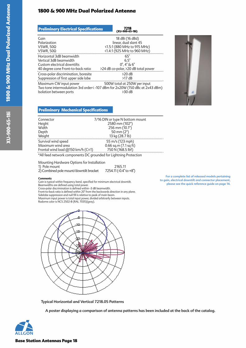
1800 & 900 MHz Dual Polarized Antenna
Gain 18 dBi (16 dBd)Polarization linear, dual slant 45VSWR, 50Ω <1.5:1 (880 MHz to 915 MHz)VSWR, 50Ω <1.4:1 (925 MHz to 960 MHz)Horizontal 3dB beamwidth 65°Vertical 3dB beamwidth 6.5°Custom electrical downtilts 0°, 4° & 6°40 degree cone Front-to-back ratio >24 dB co-polar, >20 dB total powerCross-polar discrimination, boresite >20 dBSuppression of first upper side lobe >17 dBMaximum CW input power 500W total at 250W per inputTwo tone intermodulation 3rd order< -107 dBm for 2x20W (150 dBc at 2x43 dBm)Isolation between ports >30 dB
A poster displaying a comparison of antenna patterns has been included at the back of the catalog.
Preliminary Mechanical Specifications
Connector 7/16 DIN or type N bottom mountHeight 2580 mm (102")Width 256 mm (10.1")Depth 50 mm (2")Weight 13 kg (28.7 lb)Survival wind speed 55 m/s (123 mph)Maximum wind area 0.66 sq.m (7.1 sq ft)Frontal wind load @150 km/h (C=1) 750 N (168.5 lbf)*All feed network components DC grounded for Lightning Protection
Mounting Hardware Options for Installation1) Pole mount 2165.112) Combined pole mount/downtilt bracket 7254.11 (-0.4° to +8°)
CommentsGain is typical within frequency band, specified for minimum electrical downtilt.Beamwidths are defined using total power.Cross-polar discrimination is defined within -3 dB beamwidth.Front-to-back ratio is defined within 20° from the backwards direction in any plane.Sidelobe suppression and null fill is relative to peak of main beam.Maximum input power is total input power, divided arbitrarily between inputs.Radome color is NCS 2502-B (RAL 7035)(gray).
For a complete list of released models pertaining to gain, electrical downtilt and connector placement,
please see the quick reference guide on page 14.
1800
& 9
00 M
Hz
Dua
l Po
lari
zed
Ant
enna
Typical Horizontal and Vertical 7218.05 Patterns

90
0 M
Hz A
llgo
n Lo
gP
erio
dic A
nte
nn
a900 MHz Allgon Log Periodic Antenna
Features
• Industry norm• Proven 10 year track record • Workhorse of the cellular industry• World-class manufacturing• Problem-free design• Trail blazer of front-to-back• Used as the F/B figure of merit• Used in : Europe, Asia, North America,
Central America, and South America.
Design Philosophy
Our log periodic is designed in a highly repeatableprocess that is so precise that absolutely no tuning isrequired. No adjustments are made because withAllgon quality built in by design, no adjustments arenecessary. For long life and problem free performance,Allgon uses a robust mechanical design. Two highstrength plates of aircraft quality aluminum arefastened together to form an extremely rugged pack-age. The mechanical strength is independent of theradome, which acts only to physically protect andform a weather shield for the elements.
Proper use of materials and their structure ensuresperformance integrity. In antennas the electricalperformance is directly related to mechanicalperformance. The choice of radome material iscrucial as it acts as a window between theradiating elements and the coverage area. Our UVstabilized PVC radome is resistant to moistureabsorption. Further, our radomes can withstandmechanical stresses, even at low temperaturesand long exposure to UV radiation. For corrosioninhibition, we use aircraft quality aluminum alloythat is inherently resistant to corrosion that mightbe caused by the environment.
The Allgon Log Periodic is known to be the mostconsistent performing antenna on the markettoday. While others have only a select few modelswith high Front-to-Back, Allgon’s high Front-to-Back ratio is exhibited over a complete selection ofgains and azimuth opening angles.
Performance
Bracket hardware for the Allgon Log Periodicantennas is made of only the highest quality aircraftaluminum and galvanized or stainless steel, and isavailable in non tilt and mechanical tilt for mountingto a pipe. For more information please see page 53.
Brackets
Base Station Antennas Page 19
Allgon prides itself on stringent testing require-ments with conservative, yet realistic claims of theperformance of our product offering. For moreinformation on testing procedures, see page 54.Our front-to-back ratios are specified for ±20°from 180° (worst case) to 0°.
Testing
Quality Materials
7/16 DIN Connector, Type “N” Connector
Connectors

Base Station Antennas Page 20
900
MH
z A
llgo
n Lo
g Pe
rio
dic
Ant
enna QUICK REFERENCE GUIDE
35 Degree 900 MHz ALP
Gain Part Number Description Page
16 dBi
18 dBi
7131.19.05.00 A-900-35-16i-0-N 217131.19.33.00 A-900-35-16i-0-D 21
7131.15.05.00 A-900-35-18i-0-N 217131.15.33.00 A-900-35-18i-0-D 21
900 MHzAllgon
LogPeriodic
Antenna
A - 9 0 0 - 3 5 - 1 8 i - 0 - D7/16 DINConnector
Description Detail:
AllgonLogPeriodicFamily
FrequencyBand
HorizontalBeamwidth
Electrical DowntiltAngleGain
in dBi
Antennas may be ordered using part number or description.

A-900-35-16i
Electrical Specifications 7131.19 7131.15(A-900-35-16i) (A-900-35-18i)
Base Station Antennas Page 21
900 MHz Allgon Log Periodic Antenna
Gain 16 dBi (14 dBd) 18 dBi (16 dBd)Polarization linear, vertical linear, verticalVSWR, 50Ω <1.5:1 (870 MHz to 960 MHz) <1.5:1 (870 MHz to 960 MHz)Horizontal 3dB beamwidth 35° 35°Vertical 3dB beamwidth 24° 14°Custom electrical downtilts 0° 0°40 degree cone Front-to-back ratio >30 dB >30 dBSuppression of first upper side lobe >25 dB >18 dBMaximum CW input power 500W 500WTwo tone intermodulation 3rd order <-103 dBm for 2x20W <-103 dBm for 2x20W
(146 dBc at 2x43 dBm) (146 dBc at 2x43 dBm)
A poster displaying a comparison of antenna patterns has been included at the back of the catalog.
Typical Horizontal and Vertical 7131.19 Patterns Typical Horizontal and Vertical 7131.15 Patterns
Mechanical Specifications
Connector 7/16 DIN or Type N side mountedHeight 800 mm (31.5") 1320 mm (52")Width 590 mm (23.2") 590 mm (23.2")Depth 350 mm (13.8") 350 mm (13.8")Weight 7 kg (15.4 lbs) 11 kg (23.2 lbs)Survival wind speed 70 m/s (156 mph) 70 m/s (156 mph)Maximum wind area 0.37 sq.m (4 sq.ft) 0.60 sq.m (6.5 sq.ft)Maximum wind load @150 km/h 630 N (105 lbf @ 100 mph) 675 N (171 lbf @ 100 mph)*All metallic components DC grounded for Lightning Protection
Mounting Hardware Options for Installation1) Pole mount 2165.10 2165.10 2) Combined pole mount/downtilt bracket 7254.10 (-1.5° to +34°) 7254.10 (-1° to +24°)
CommentsGain is typical within frequency band.Front-to-back ratio is defined within 20° from the backwards direction in any plane.Sidelobe suppression and null fill is relative to peak of main beam.Radome color is NCS 2502-B (RAL 7035)(gray).
For a complete list of released models pertaining to gain, electrical downtilt and connector placement,
please see the quick reference guide on page 22.
900 MH
z Allgo
n Log Perio
dicA
ntennaA
-900-35-18i
900 MH
z City Panel A
ntenna900 MHz City Panel Antenna
Features
• Unique structure providing a high front-to-back ratio
• Used in: Europe, Africa, Middle East, Asia,South America, and North America.
• Pattern shaping to define Upper LobeSuppression and Lower Null Fill
• Helped pioneer the wide spread use ofvertical pattern shaping for enhancedsystem performance
Design Philosophy
Quality Materials
The Allgon City Panel Antenna has a robustdesign, which yields the same Front-to-Back per-formance as a log periodic through uniquegeometric configuration. The pattern shaping inthe upper lobe suppression and lower null fill isunique and ensures maximum coverage andcontainment. The Allgon City antenna has helpedpioneer the wide spread use of pattern shaping forenhanced system performance.
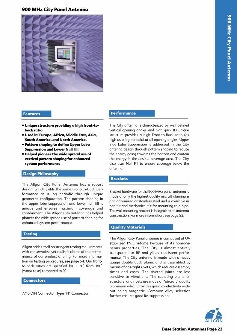
The Allgon City Panel antenna is composed of UVstabilized PVC radome because of its homoge-neous properties. The City is almost entirelytransparent to RF and yields consistent perfor-mance. The City antenna is made with a heavygauge double back plane, and is assembled bymeans of gas-tight rivets, which reduces assemblytimes and costs. The riveted joints are lesssensitive to vibrations. The radiating elements,structure, and rivets are made of “aircraft" qualityaluminum which provides good conductivity with-out being magnetic. Common alloy selectionfurther ensures good IM suppression.
The City antenna is characterized by well definedvertical opening angles and high gain. Its uniquestructure provides a high Front-to-Back ratio (ashigh as a log periodic) at all opening angles. UpperSide Lobe Suppression is addressed in the Cityantenna design through pattern shaping to reducethe energy going towards the horizon and containthe energy in the desired coverage area. The Cityalso uses Null Fill to ensure coverage below theantenna.
Performance
Bracket hardware for the 900 MHz panel antenna ismade of only the highest quality aircraft aluminumand galvanized or stainless steel and is available innon tilt and mechanical tilt for mounting to a pipe.The wall mounting bracket is integral to the antennaconstruction. For more information, see page 53.
Brackets
7/16 DIN Connector, Type “N” Connector
Connectors
Base Station Antennas Page 22
Allgon prides itself on stringent testing requirementswith conservative, yet realistic claims of the perfor-mance of our product offering. For more informa-tion on testing procedures, see page 54. Our front-to-back ratios are specified for ± 20° from 180°(worst case) compared to 0°.
Testing

Base Station Antennas Page 23
900
MH
z C
ity
Pane
l Ant
enna
QUICK REFERENCE GUIDE
90 Degree 900 MHz Panel
Gain Part Number Description Page
8.5 dBi
14 dBi
15.5 dBi
16.5 dBi
7144.11.05.00 CI-900-90-8.5i-0-N 267144.11.33.00 CI-900-90-8.5i-0-D 26
7144.14.33.00 CI-900-90-14i-0-D 27
7144.16.33.00 CI-900-90-15.5i-0-D 277144.16.33.04 CI-900-90-15.5i-4-D 27
7144.38.33.00 CI-900-90-16.5i-0-D 287144.38.33.04 CI-900-90-16.5i-4-D 287144.38.33.05 CI-900-90-16.5i-5-D 28
60 Degree 900 MHz Panel
Gain Part Number Description Page
10 dBi
13 dBi
15.5 dBi
17 dBi
18 dBi
7143.11.05.00 CI-900-60-10i-0-N 247143.11.33.00 CI-900-60-10i-0-D 24
7143.12.05.00 CI-900-60-13i-0-N 247143.12.33.00 CI-900-60-13i-0-D 24
7143.14.05.00 CI-900-60-15.5i-0-N 257143.14.33.00 CI-900-60-15.5i-0-D 25
7143.16.05.00 CI-900-60-17i-0-N 257143.16.33.00 CI-900-60-17i-0-D 257143.16.33.04 CI-900-60-17i-4-D 257143.16.33.06 CI-900-60-17i-6-D 257143.16.33.08 CI-900-60-17i-8-D 257143.16.33.09 CI-900-60-17i-9-D 25
7143.38.05.00 CI-900-60-18i-0-N 267143.38.33.00 CI-900-60-18i-0-D 267143.38.33.02 CI-900-60-18i-2-D 267143.38.33.05 CI-900-60-18i-5-D 26
105 Degree 900 MHz Panel
Gain Part Number Description Page13.5 dBi 7145.14.33.00 CI-900-105-13.5i-0-D 28
120 Degree 900 MHz Panel
Gain Part Number Description Page10.5 dBi
13 dBi
14.5 dBi
15.5 dBi
7146.12.05.00 CI-900-120-10.5i-0-N 29
7146.14.05.00 CI-900-120-13i-0-N 297146.14.33.00 CI-900-120-13i-0-D 29
7146.16.05.00 CI-900-120-14.5i-0-N 307146.16.33.00 CI-900-120-14.5i-0-D 307146.16.33.08 CI-900-120-14.5i-8-D 30
7146.38.05.00 CI-900-120-15.5i-0-N 307146.38.33.00 CI-900-120-15.5i-0-D 307146.38.33.05 CI-900-120-15.5i-5-D 30
C I - 9 0 0 - 6 0 - 1 5 . 5 i - 0 - D7/16 DINConnector
Description Detail:
CityPanelFamily
FrequencyBand
HorizontalBeamwidth
Electrical DowntiltAngleGain
in dBi
A trailing B indicates connector placement on the back panel, no B indicates connector placement on the bottom.
Antennas may be ordered using part number or description.

Base Station Antennas Page 24
900 MHz City Panel Antenna
A poster displaying a comparison of antenna patterns has been included at the back of the catalog.
Typical Horizontal and Vertical 7143.11 Patterns Typical Horizontal and Vertical 7143.12 Patterns
For a complete list of released models pertaining to gain, electrical downtilt and connector placement,
please see the quick reference guide on page 31.
900 MH
z City Panel A
ntennaCI-900-60-10i
Electrical Specifications 7143.11 7143.12(CI-900-60-10i) (CI-900-60-13i)
Gain 10 dBi (8 dBd) 13 dBi (11 dBd)Polarization linear, vertical linear, verticalVSWR, 50Ω <1.4:1 (870 MHz to 925 MHz) <1.4:1 (870 MHz to 925 MHz)VSWR, 50Ω <1.2:1 (925 MHz to 960 MHz) <1.2:1 (925 MHz to 960 MHz)Horizontal 3dB beamwidth 60° 60°
Vertical 3dB beamwidth 65° 30°Custom electrical downtilts 0° 0°40 degree cone Front-to-back ratio >30 dB >30 dBSuppression of first upper side lobe N/A >16Maximum CW input power 300W 500WTwo tone intermodulation 3rd order <-103 dBm for 2x20W <-103 dBm for 2x20W
(146 dBc at 2x43 dBm) (146 dBc at 2x43 dBm)
Mechanical Specifications
Connector 7/16 DIN or Type N on bottomHeight 300 mm (11.8") 600 mm (23.6")Width 300 mm (11.8") 300 mm (11.8")Depth 130 mm (5.1") 130 mm (5.1")Weight 2.3 kg (5.1 lbs) 5 kg (11.1 lbs)Survival wind speed 70 m/s (156 mph) 70 m/s (156 mph)Maximum wind area 0.09 sq.m (0.97 sq.ft) 0.18 sq.m (1.9 sq.ft)Frontal wind load @150 km/h (C=1) 100 N (25.5 lbf @ 100 mph) 200 N (50.9 lbf @ 100 mph)*All metallic components DC grounded for Lightning Protection
Mounting Hardware Options for Installation1) Pole mount 2165.10 2165.102) Combined pole mount/downtilt bracket 7254.10 (-2.5° to +64°) 7254.10 (-1.4° to +32°)
CommentsGain is typical within frequency band.Front-to-back ratio is defined within 20° from the backwards direction in any plane.Sidelobe suppression and null fill is relative to peak of main beam.Radome color is NCS 2502-B (RAL 7035)(gray).
CI-900-60-13i

CI-9
00-6
0-17
i
Base Station Antennas Page 25
900 MHz City Panel Antenna
A poster displaying a comparison of antenna patterns has been included at the back of the catalog.
For a complete list of released models pertaining to gain, electrical downtilt and connector placement,
please see the quick reference guide on page 31.
900
MH
z C
ity
Pane
l Ant
enna
CI-9
00-6
0-15
.5i
Typical Horizontal and Vertical 7143.14 Patterns Typical Horizontal and Vertical 7143.16 Patterns
Electrical Specifications 7143.14 7143.16(CI-900-60-15.5i) (CI-900-60-17i)
Gain 15.5 dBi (13.5 dBd) 17 dBi (15 dBd)Polarization linear, vertical linear, verticalVSWR, 50Ω <1.4:1 (870 MHz to 925 MHz) <1.4:1 (870 MHz to 925 MHz)VSWR, 50Ω <1.2:1 (925 MHz to 960 MHz) <1.2:1 (925 MHz to 960 MHz)Horizontal 3dB beamwidth 60° 60°Vertical 3dB beamwidth 16° 11°Custom electrical downtilts 0° 0°, 4°, 6°, 8°, & 9°40 degree cone Front-to-back ratio >30 dB >30 dBSuppression of first upper side lobe >18 dB >18 dBFirst lower null fill >-21 dB >-12 dBMaximum CW input power 500W 500WTwo tone intermodulation 3rd order <-103 dBm for 2x20W <-103 dBm for 2x20W
(146 dBc at 2x43 dBm) (146 dBc at 2x43 dBm)
Mechanical Specifications
Connector 7/16 DIN or Type N on bottom 7/16 DIN or Type N on bottomHeight 1200 mm (47.2") 1800 mm (70.9")Width 300 mm (11.8") 300 mm (11.8")Depth 130 mm (5.1") 130 mm (5.1")Weight 9.5 kg (21 lbs) 14 kg (30.9 lbs)Survival wind speed 70 m/s (156 mph) 70 m/s (156 mph)Maximum wind area 0.36 sq.m (3.9 sq.ft) 0.54 sq.m (5.8 sq.ft)Frontal wind load @150 km/h (C=1) 400 N (102 lbf @ 100 mph) 600 N (153 lbf @ 100 mph)*All metallic components DC grounded for Lightning Protection
Mounting Hardware Options for Installation1) Pole mount 2165.10 2165.102) Combined pole mount/downtilt bracket 7254.10 (-0.7° to +16°) 7254.10 (-0.5° to +11°)
CommentsGain is typical within frequency band.Front-to-back ratio is defined within 20° from the backwards direction in any plane.Sidelobe suppression and null fill is relative to peak of main beam.Radome color is NCS 2502-B (RAL 7035)(gray).

CI-900-60-18i
Base Station Antennas Page 26
900 MHz City Panel Antenna
A poster displaying a comparison of antenna patterns has been included at the back of the catalog.
Typical Horizontal and Vertical 7143.38 Patterns Typical Horizontal and Vertical 7144.11 Patterns
For a complete list of released models pertaining to gain, electrical downtilt and connector placement,
please see the quick reference guide on page 31.
900 MH
z City Panel A
ntennaCI-900-90-8.5i
Electrical Specifications 7143.38 7144.11(CI-900-60-18i) (CI-900-90-8.5i)
Gain 18 dBi (16 dBd) 8.5 dBi (6.5 dBd)Polarization linear, vertical linear, verticalVSWR, 50Ω <1.4:1 (870 MHz to 925 MHz) <1.4:1 (870 MHz to 925 MHz)VSWR, 50Ω <1.2:1 (925 MHz to 960 MHz) <1.2:1 (925 MHz to 960 MHz)Horizontal 3dB beamwidth 60° 90°Vertical 3dB beamwidth 7° 65°Custom electrical downtilts 0°, 2°, & 5° 0°40 degree cone Front-to-back ratio >30 dB >28 dBSuppression of first upper side lobe >17 dB N/AFirst lower null fill N/A N/AMaximum CW input power 500W 300WTwo tone intermodulation 3rd order <-103 dBm for 2x20W <-103 dBm for 2x20W
(146 dBc at 2x43 dBm) (146 dBc at 2x43 dBm)
Mechanical Specifications
Connector 7/16 DIN or Type N on bottomHeight 2300 mm (90.5") 300 mm (11.8")Width 300 mm (11.8") 300 mm (11.8")Depth 130 mm (5.1") 130 mm (5.1")Weight 17 kg (37.5 lbs) 2.3 kg (5.1 lbs)Survival wind speed 70 m/s (156 mph) 70 m/s (156 mph)Maximum wind area 0.69 sq.m (7.4 sq.ft) 0.09 sq.m (0.97 sq.ft)Frontal wind load @150 km/h (C=1) 760 N (195 lbf @ 100 mph) 100 N (25.5 lbf @ 100 mph)*All metallic components DC grounded for Lightning Protection
Mounting Hardware Options for Installation1) Pole mount 2165.10 2165.102) Combined pole mount/downtilt bracket 7254.10 (-0.4° to +8°) 7254.10 (-2.5° to +64°)
CommentsGain is typical within frequency band.Front-to-back ratio is defined within 20° from the backwards direction in any plane.Sidelobe suppression and null fill is relative to peak of main beam.Radome color is NCS 2502-B (RAL 7035)(gray).
CI-9
00-9
0-15
.5i
Base Station Antennas Page 27
900 MHz City Panel Antenna
A poster displaying a comparison of antenna patterns has been included at the back of the catalog.
For a complete list of released models pertaining to gain, electrical downtilt and connector placement,
please see the quick reference guide on page 31.
900
MH
z C
ity
Pane
l Ant
enna
CI-9
00-9
0-14
i
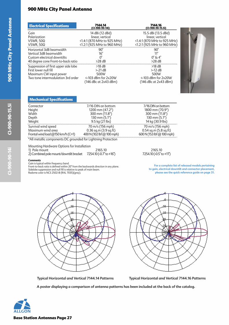
Typical Horizontal and Vertical 7144.14 Patterns Typical Horizontal and Vertical 7144.16 Patterns
Electrical Specifications 7144.14 7144.16(CI-900-90-14i) (CI-900-90-15.5i)
Gain 14 dBi (12 dBd) 15.5 dBi (13.5 dBd)Polarization linear, vertical linear, verticalVSWR, 50Ω <1.4:1 (870 MHz to 925 MHz) <1.4:1 (870 MHz to 925 MHz)VSWR, 50Ω <1.2:1 (925 MHz to 960 MHz) <1.2:1 (925 MHz to 960 MHz)Horizontal 3dB beamwidth 90° 90°Vertical 3dB beamwidth 16° 11°Custom electrical downtilts 0° 0° & 4°40 degree cone Front-to-back ratio >28 dB >28 dBSuppression of first upper side lobe >18 dB >18 dBFirst lower null fill >-21 dB >-12 dBMaximum CW input power 500W 500WTwo tone intermodulation 3rd order <-103 dBm for 2x20W <-103 dBm for 2x20W
(146 dBc at 2x43 dBm) (146 dBc at 2x43 dBm)
Mechanical Specifications
Connector 7/16 DIN on bottom 7/16 DIN on bottomHeight 1200 mm (47.2") 1800 mm (70.9")Width 300 mm (11.8") 300 mm (11.8")Depth 130 mm (5.1") 130 mm (5.1")Weight 9.5 kg (21 lbs) 14 kg (30.9 lbs)Survival wind speed 70 m/s (156 mph) 70 m/s (156 mph)Maximum wind area 0.36 sq.m (3.9 sq.ft) 0.54 sq.m (5.8 sq.ft)Frontal wind load @150 km/h (C=1) 400 N (102 lbf @ 100 mph) 600 N (153 lbf @ 100 mph)*All metallic components DC grounded for Lightning Protection
Mounting Hardware Options for Installation1) Pole mount 2165.10 2165.102) Combined pole mount/downtilt bracket 7254.10 (-0.7° to +16°) 7254.10 (-0.5° to +11°)
CommentsGain is typical within frequency band.Front-to-back ratio is defined within 20° from the backwards direction in any plane.Sidelobe suppression and null fill is relative to peak of main beam.Radome color is NCS 2502-B (RAL 7035)(gray).

CI-900-90-16.5i
Base Station Antennas Page 28
900 MHz City Panel Antenna
A poster displaying a comparison of antenna patterns has been included at the back of the catalog.
Typical Horizontal and Vertical 7144.38 Patterns Typical Horizontal and Vertical 7145.14 Patterns
For a complete list of released models pertaining to gain, electrical downtilt and connector placement,
please see the quick reference guide on page 31.
900 MH
z City Panel A
ntennaCI-900-105-13.5i
Electrical Specifications 7144.38 7145.14(CI-900-90-16.5i) (CI-900-105-13.5i)
Gain 16.5 dBi (14.5 dBd ) 13.5 dBi (11.5 dBd)Polarization linear, vertical linear, verticalVSWR, 50Ω <1.4:1 (870 MHz to 925 MHz) <1.4:1 (870 MHz to 925 MHz)VSWR, 50Ω <1.2:1 (925 MHz to 960 MHz) <1.2:1 (925 MHz to 960 MHz)Horizontal 3dB beamwidth 90° 105°Vertical 3dB beamwidth 7° 16°Custom electrical downtilts 0°, 4°, & 5° 0°40 degree cone Front-to-back ratio >28 dB >25 dBSuppression of first upper side lobe >17 dB >18 dBFirst lower null fill N/A >-21 dBMaximum CW input power 500W 500WTwo tone intermodulation 3rd order <-103 dBm for 2x20W <-103 dBm for 2x20W
(146 dBc at 2x43 dBm) (146 dBc at 2x43 dBm)
Mechanical Specifications
Connector 7/16 DIN or Type N on bottomHeight 2300 mm (90.5") 1200 mm (47.2")Width 300 mm (11.8") 300 mm (11.8")Depth 130 mm (5.1") 130 mm (5.1")Weight 17 kg (37.5 lbs) 9.5 kg (21 lbs)Survival wind speed 70 m/s (156 mph) 70 m/s (156 mph)Maximum wind area 0.69 sq.m (7.4 sq.ft) 0.36 sq.m (3.9 sq.ft)Frontal wind load @150 km/h (C=1) 760 N (195 lbf @ mph) 400 N (102 lbf @ 100 mph)*All metallic components DC grounded for Lightning Protection
Mounting Hardware Options for Installation1) Pole mount 2165.10 2165.102) Combined pole mount/downtilt bracket 7254.10 (-0.4° to +8°) 7254.10 (-0.7° to +16°)
CommentsGain is typical within frequency band.Front-to-back ratio is defined within 20° from the backwards direction in any plane.Sidelobe suppression and null fill is relative to peak of main beam.Radome color is NCS 2502-B (RAL 7035)(gray).

Base Station Antennas Page 29
900 MHz City Panel Antenna
A poster displaying a comparison of antenna patterns has been included at the back of the catalog.
For a complete list of released models pertaining to gain, electrical downtilt and connector placement,
please see the quick reference guide on page 31.
Typical Horizontal and Vertical 7146.12 Patterns Typical Horizontal and Vertical 7146.14 Patterns
Electrical Specifications 7146.12 7146.14(CI-900-120-10.5i) (CI-900-120-13i)
Gain 10.5 dBi (8.5 dBd) 13 dBi (11 dBd)Polarization linear, vertical linear, verticalVSWR, 50Ω <1.4:1 (870 MHz to 925 MHz) <1.4:1 (870 MHz to 925 MHz)VSWR, 50Ω <1.2:1 (925 MHz to 960 MHz) <1.2:1 (925 MHz to 960 MHz)Horizontal 3dB beamwidth 120° 120°Vertical 3dB beamwidth 30° 16°Custom electrical downtilts 0° 0°40 degree cone Front-to-back ratio >25 dB >25 dBSuppression of first upper side lobe >16 dB >18 dBFirst lower null fill N/A >-21 dBMaximum CW input power 500W 500WTwo tone intermodulation 3rd order <-103 dBm for 2x20W <-103 dBm for 2x20W
(146 dBc at 2x43 dBm) (146 dBc at 2x43 dBm)
Mechanical Specifications
Connector Type N on bottom 7/16 DIN or Type N on bottomHeight 600 mm (23.6") 1200 mm (47.2")Width 300 mm (11.8") 300 mm (11.8")Depth 130 mm (5.1") 130 mm (5.1")Weight 5 kg (11 lbs) 9.5 kg (21 lbs)Survival wind speed 70 m/s (156 mph) 70 m/s (156 mph)Maximum wind area 0.09 sq.m (1.9 sq.ft) 0.36 sq.m (3.9 sq.ft)Frontal wind load @150 km/h (C=1) 200 N (50.9 lbf @ 100 mph) 400 N (102 lbf @ 100 mph)*All metallic components DC grounded for Lightning Protection
Mounting Hardware Options for Installation1) pole mount 2165.10 2165.102) combined pole mount/downtilt bracket 7254.10 (-1.4° to +32°) 7254.10 (-0.7° to +16°)
CommentsGain is typical within frequency band.Front-to-back ratio is defined within 20° from the backwards direction in any plane.Sidelobe suppression and null fill is relative to peak of main beam.Radome color is NCS 2502-B (RAL 7035)(gray).
CI-9
00-1
20-1
3i90
0 M
Hz
Cit
y Pa
nel A
nten
naCI
-900
-120
-10.
5i
Base Station Antennas Page 30
900 MHz City Panel Antenna
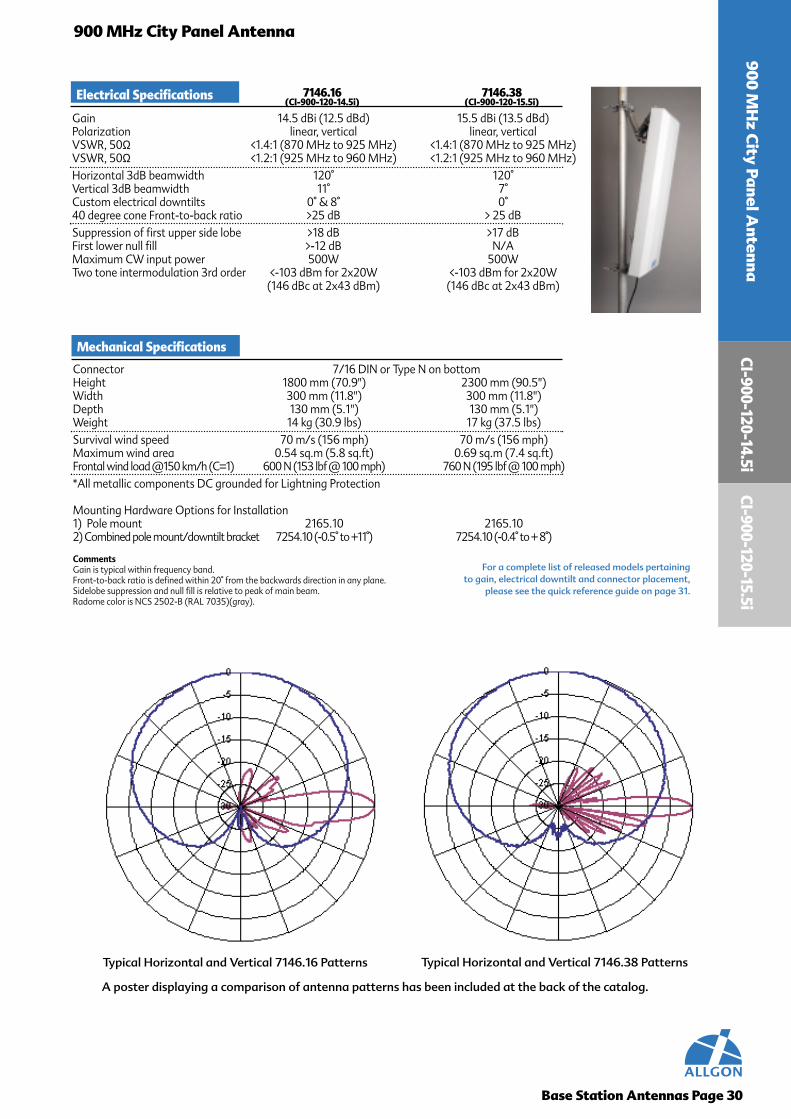
A poster displaying a comparison of antenna patterns has been included at the back of the catalog.
Typical Horizontal and Vertical 7146.16 Patterns Typical Horizontal and Vertical 7146.38 Patterns
For a complete list of released models pertaining to gain, electrical downtilt and connector placement,
please see the quick reference guide on page 31.
900 MH
z City Panel A
ntennaCI-900-120-14.5i
Electrical Specifications 7146.16 7146.38(CI-900-120-14.5i) (CI-900-120-15.5i)
Gain 14.5 dBi (12.5 dBd) 15.5 dBi (13.5 dBd)Polarization linear, vertical linear, verticalVSWR, 50Ω <1.4:1 (870 MHz to 925 MHz) <1.4:1 (870 MHz to 925 MHz)VSWR, 50Ω <1.2:1 (925 MHz to 960 MHz) <1.2:1 (925 MHz to 960 MHz)Horizontal 3dB beamwidth 120° 120°Vertical 3dB beamwidth 11° 7°Custom electrical downtilts 0° & 8° 0°40 degree cone Front-to-back ratio >25 dB > 25 dBSuppression of first upper side lobe >18 dB >17 dBFirst lower null fill >-12 dB N/AMaximum CW input power 500W 500WTwo tone intermodulation 3rd order <-103 dBm for 2x20W <-103 dBm for 2x20W
(146 dBc at 2x43 dBm) (146 dBc at 2x43 dBm)
Mechanical Specifications
Connector 7/16 DIN or Type N on bottomHeight 1800 mm (70.9") 2300 mm (90.5")Width 300 mm (11.8") 300 mm (11.8")Depth 130 mm (5.1") 130 mm (5.1")Weight 14 kg (30.9 lbs) 17 kg (37.5 lbs)Survival wind speed 70 m/s (156 mph) 70 m/s (156 mph)Maximum wind area 0.54 sq.m (5.8 sq.ft) 0.69 sq.m (7.4 sq.ft)Frontal wind load @150 km/h (C=1) 600 N (153 lbf @ 100 mph) 760 N (195 lbf @ 100 mph)*All metallic components DC grounded for Lightning Protection
Mounting Hardware Options for Installation1) Pole mount 2165.10 2165.102) Combined pole mount/downtilt bracket 7254.10 (-0.5° to +11°) 7254.10 (-0.4° to + 8°)
CommentsGain is typical within frequency band.Front-to-back ratio is defined within 20° from the backwards direction in any plane.Sidelobe suppression and null fill is relative to peak of main beam.Radome color is NCS 2502-B (RAL 7035)(gray).
CI-900-120-15.5i

900 MH
z Adjustable Electrical
Dow
ntilt City Panel A
ntenna900 MHz Adjustable Electrical Downtilt City Panel Antenna
Base Station Antennas Page 31
Features
• Field adjustable from 0 to 17 degrees in one degree increments
• Can be implemented without downtilt brackets – improved aesthetics
• Innovative patented design
• Aesthetically pleasing to address zoning issues
Design Philosophy
Quality Materials
The Allgon Adjustable Electrical DowntiltAntenna has a robust design, which yields thesame Front-to-Back performance as a log periodicthrough unique geometric configuration. Thepattern shaping in the upper lobe suppression isunique and ensures maximum coverage andcontainment. The Allgon 800 MHz panel antennahas helped pioneer the wide spread use of patternshaping for enhanced system performance.
The Allgon City AEDT Panel antenna is composedof UV stabilized PVC radome because of its ho-mogenous properties. The radome is almostentirely transparent to RF and yields consistentperformance. The City antenna is made with aheavy gauge double back plane, and is assembledby means of gas-tight rivets, which reducesassembly times and costs. The riveted joints areless sensitive to vibrations. The radiating element,structure and rivets are made of “Aircraft" qualityaluminum which provides good conductivity with-out being magnetic. Common alloy furtherensures good IM suppression.
The City AEDT antenna is characterized by welldefined vertical opening angles and high gain. Itsunique structure provides a high Front-to-Backratio at all opening angles. Upper Side LobeSuppression is addressed in the City antennadesign through pattern shaping to reduce the en-ergy going towards the horizon and contain theenergy in the desired coverage area.
Performance
Bracket hardware for the 900 MHz panelantenna is made of only the highest qualityaircraft aluminum and galvanized or stainlesssteel, and is available for non-tilt and mechanicaltilt for mounting to a pipe. The wall mountingbracket is integral to the antenna construction.For more information, see page 53.
Brackets
7/16 DIN Connector, Type “N” Connector
Connectors
Allgon prides itself on stringent testing require-ments with conservative, yet realistic claims of theperformance of our product offering. For more in-formation on testing procedures, see page 54.Our front-to-back ratios are specified for ±20° from180° (worst case) to 0°.
Testing

900
MH
z A
djus
tabl
e El
ectr
ical
D
ownt
ilt C
ity
Pane
l Ant
enna
QUICK REFERENCE GUIDE
Base Station Antennas Page 32
60 Degree Adjustable ElectricalDowntilt Panel
Gain Part Number Description Page
15 dBi 7143.14.05.50 CI-900-60-15i-A-N 337143.14.33.50 CI-900-60-15i-A-D 33
90 Degree Adjustable ElectricalDowntilt Panel
Gain Part Number Description Page
13.5 dBi 7144.14.05.50 CI-900-90-13.5i-A-N 337144.14.33.50 CI-900-90-13.5i-A-D 33
105 Degree Adjustable ElectricalDowntilt Panel
Gain Part Number Description Page
13 dBi 7145.14.05.50 CI-900-105-13i-A-N 347145.14.33.50 CI-900-105-13i-A-D 34
120 Degree Adjustable ElectricalDowntilt Panel
Gain Part Number Description Page
12 dBi 7146.14.05.50 CI-900-120-12i-A-N 347146.14.33.50 CI-900-120-12i-A-D 34
900 MHzAdjustable
Electrical DowntiltCity Panel Antenna
C I - 9 0 0 - 6 0 - 1 5 i - A - D7/16 DINConnector
Description Detail:
CityPanelFamily
FrequencyBand
HorizontalBeamwidth
AdjustableElectrical DowntiltGain
in dBi
A trailing B indicates connector placement on the back panel, no B indicates connector placement on the bottom.
Antennas may be ordered using part number or description.
Gain varies depending on electrical downtilt setting.Rating is for an average peak gain.
CI-900-60-15i
Base Station Antennas Page 33
900 MHz Adjustable Electrical Downtilt City Panel Antenna
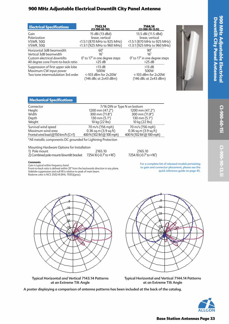
A poster displaying a comparison of antenna patterns has been included at the back of the catalog.
Typical Horizontal and Vertical 7143.14 Patterns at an Extreme Tilt Angle
Typical Horizontal and Vertical 7144.14 Patterns at an Extreme Tilt Angle
For a complete list of released models pertaining to gain and connector placement, please see the
quick reference guide on page 45.
900 MH
z Adjustable Electrical
Dow
ntilt City Panel A
ntennaCI-900-90-13.5i
Electrical Specifications 7143.14 7144.14(CI-900-60-15i) (CI-900-90-13.5i)
Gain 15 dBi (13 dBd) 13.5 dBi (11.5 dBd)Polarization linear, vertical linear, verticalVSWR, 50Ω <1.5:1 (870 MHz to 925 MHz) <1.5:1 (870 MHz to 925 MHz)VSWR, 50Ω <1.3:1 (925 MHz to 960 MHz) <1.3:1 (925 MHz to 960 MHz)Horizontal 3dB beamwidth 60° 90°Vertical 3dB beamwidth 16° 16°Custom electrical downtilts 0° to 17° in one degree steps 0° to 17° in one degree steps40 degree cone Front-to-back ratio >25 dB >25 dBSuppression of first upper side lobe >13 dB >13 dBMaximum CW input power 500W 500WTwo tone intermodulation 3rd order <-103 dBm for 2x20W <-103 dBm for 2x20W
(146 dBc at 2x43 dBm) (146 dBc at 2x43 dBm)
Mechanical Specifications
Connector 7/16 DIN or Type N on bottomHeight 1200 mm (47.2") 1200 mm (47.2")Width 300 mm (11.8") 300 mm (11.8")Depth 130 mm (5.1") 130 mm (5.1")Weight 10 kg (22 lbs) 10 kg (22 lbs)Survival wind speed 70 m/s (156 mph) 70 m/s (156 mph)Maximum wind area 0.36 sq.m (3.9 sq.ft) 0.36 sq.m (3.9 sq.ft)Frontal wind load @150 km/h (C=1) 400 N (102 lbf @ 100 mph) 400 N (102 lbf @ 100 mph)*All metallic components DC grounded for Lightning Protection
Mounting Hardware Options for Installation1) Pole mount 2165.10 2165.102) Combined pole mount/downtilt bracket 7254.10 (-0.7° to +16°) 7254.10 (-0.7° to +16°)
CommentsGain is typical within frequency band.Front-to-back ratio is defined within 20° from the backwards direction in any plane.Sidelobe suppression and null fill is relative to peak of main beam.Radome color is NCS 2502-B (RAL 7035)(gray).

CI-9
00-1
20-1
2i
Base Station Antennas Page 34
900 MHz Adjustable Electrical Downtilt City Panel Antenna
A poster displaying a comparison of antenna patterns has been included at the back of the catalog.
For a complete list of released models pertaining to gain and connector placement, please see the
quick reference guide on page 45.
900
MH
z A
djus
tabl
e El
ectr
ical
D
ownt
ilt C
ity
Pane
l Ant
enna
CI-9
00-1
05-1
3i
Typical Horizontal and Vertical 7145.14 Patterns at anExtreme Tilt Angle
Typical Horizontal and Vertical 7146.14 Patterns at anExtreme Tilt Angle
Electrical Specifications 7145.14 7146.14(CI-900-105-13i) (CI-900-120-12i)
Gain 13 dBi (11 dBd) 12 dBi (10 dBd)Polarization linear, vertical linear, verticalVSWR, 50Ω <1.5:1 (870 MHz to 925 MHz) <1.5:1 (870 MHz to 925 MHz)VSWR, 50Ω <1.3:1 (925 MHz to 960 MHz) <1.3:1 (925 MHz to 960 MHz)Horizontal 3dB beamwidth 105° 120°Vertical 3dB beamwidth 16° 16°Custom electrical downtilts 0° to 17° in one degree steps 0° to 17° in one degree steps40 degree cone Front-to-back ratio >20 dB >20 dBSuppression of first upper side lobe >13 dB >13 dBMaximum CW input power 500W 500WTwo tone intermodulation 3rd order <-103 dBm for 2x20W <-103 dBm for 2x20W
(146 dBc at 2x43 dBm) (146 dBc at 2x43 dBm)
Mechanical Specifications
Connector 7/16 DIN or Type N on bottomHeight 1200 mm (47.2") 1200 mm (47.2")Width 300 mm (11.8") 300 mm (11.8")Depth 130 mm (5.1") 130 mm (5.1")Weight 10 kg (22 lbs) 10 kg (22 lbs)Survival wind speed 70 m/s (156 mph) 70 m/s (156 mph)Maximum wind area 0.36 sq.m (3.9 sq.ft) 0.36 sq.m (3.9 sq.ft)Frontal wind load @150 km/h (C=1) 400 N (102 lbf @ 100 mph) 400 N (102 lbf @ 100 mph)*All metallic components DC grounded for Lightning Protection
Mounting Hardware Options for Installation1) Pole mount 2165.10 2165.102) Combined pole mount/downtilt bracket 7254.10 (-0.7° to +16°) 7254.10 (-0.7° to +16°)
CommentsGain is typical within frequency band.Front-to-back ratio is defined within 20° from the backwards direction in any plane.Sidelobe suppression and null fill is relative to peak of main beam.Radome color is NCS 2502-B (RAL 7035)(gray).

900 MHz Urban Panel Antenna
Base Station Antennas Page 35
900 MH
z Urban
Panel Antenna
Features
Design Philosophy
Quality Materials
The Allgon antenna is designed in a repeatableprocedure which requires no tuning or modifica-tion, with the specification being the same fromproduct to product. The Urban antenna has arobust mechanical design which does not rely onthe radome for support. The radome, which is onlyfor weatherproofing, is set inside the endcaps andallows for thermal expansion.
Proper use of materials and their structure ensuresperformance integrity. In antennas, the electricalperformance is directly related to mechanicalperformance. The choice of radome materials iscrucial since it acts as a window between theradiating elements and the coverage area. Our UVstabilized PVC radome is resistant to moistureabsorption. Furthermore, our radomes canwithstand mechanical stresses, even at lowtemperatures and long exposure to UV radiation.For corrosion inhibition, we use aircraft qualityaluminum alloy that is inherently resistant tocorrosion caused by the environment.
The Allgon antennas have verified verticalpattern performance on 100% of the antennas.The product line has a better than 1.4:1 VSWRreceive and 1.3:1 transmit. The antenna hasconsistent, reliable performance from frequencyto frequency and product to product.
Performance
Bracket hardware for the 900 MHz antenna ismade of only the highest quality aircraftaluminum and galvanized or stainless steel, and isavailable in non-tilt and mechanical tilt formounting to a pipe. The 900 MHz antenna canalso be flush mounted with tilt on panning. Formore information, see page 53.
Brackets
7/16 DIN Connector, Type “N” Connector
Connectors
Allgon prides itself on stringent testing require-ments with conservative, yet realistic claims of theperformance of our product offering. For more in-formation on testing procedures, see page 54. Ourfront-to-back ratios are specified for ±20° from 180°(worst case) to 0°.
Testing
• Same pattern across the entire frequencyband
• 100% VSWR testing• Superior vertical pattern shaping for
interference reduction• 100% verified for vertical pattern
performance• Mechanical design allows for thermal
expansion• Aesthetically pleasing

Base Station Antennas Page 36
900
MH
z U
rban
Ant
enna
QUICK REFERENCE GUIDE
90 Degree 900 MHz Flat Panel65 Degree 900 MHz Flat Panel
Gain Part Number Description Page
13 dBi
17.5 dBi
15.5 dBi
17 dBi
7225.03 U-900-65-13i-0-N 377225.04 U-900-65-13i-0-D 37
7226.05 U-900-65-15.5i-0-N 377226.03 U-900-65-15.5i-6-D 377226.04 U-900-65-15.5i-0-D 37
7227.05 U-900-65-17i-0-N 387227.04 U-900-65-17i-0-D 387227.06 U-900-65-17i-4-D 387227.03 U-900-65-17i-6-D 38
7228.03 U-900-65-18i-0-N 387228.04 U-900-65-18i-0-D 38
7228.06 U-900-65-17.5i-6-D 38
18 dBi
Gain Part Number Description Page
12 dBi
14 dBi
15 dBi
7230.03 U-900-90-12i-0-N 397230.04 U-900-90-12i-0-D 39
7231.03 U-900-90-14i-0-N 397231.04 U-900-90-14i-0-D 397231.06 U-900-90-14i-6-D 39
7232.03 U-900-90-15i-0-N 407232.04 U-900-90-15i-0-D 407232.07 U-900-90-15i-4-D 40
7233.03 U-900-90-16.5i-0-N 407233.04 U-900-90-16.5i-0-D 407233.06 U-900-90-16.5i-6-D 40
16.5 dBi
900 MHzUrbanAntenna
U - 9 0 0 - 6 5 - 1 5 . 5 i - 0 - D7/16 DINConnector
Description Detail:
UrbanFamily
FrequencyBand
HorizontalBeamwidth
Electrical DowntiltAngleGain
in dBi
Antennas may be ordered using part number or description.

Base Station Antennas Page 37
900 MHz Urban Antenna
A poster displaying a comparison of antenna patterns has been included at the back of the catalog.
Typical Horizontal and Vertical 7225.04 Patterns Typical Horizontal and Vertical 7226.04 Patterns
For a complete list of released models pertaining to gain, electrical downtilt and connector placement,
please see the quick reference guide on page 49.
900 MH
z Urban A
ntennaU
-900-65-13i
Electrical Specifications 7225 7226(U-900-65-13i) (U-900-65-15.5i)
Gain 13 dBi (11 dBd) 15.5 dBi (13.5 dBd)Polarization linear, vertical linear, verticalVSWR, 50Ω <1.4:1 (870 MHz to 925 MHz) <1.4:1 (870 MHz to 925 MHz)VSWR, 50Ω <1.3:1 (925 MHz to 960 MHz) <1.3:1 (925 MHz to 960 MHz)Horizontal 3dB beamwidth 65° 65°Vertical 3dB beamwidth 26° 14°Custom electrical downtilts 0° 0° & 6°40 degree cone Front-to-back ratio >25 dB >23 dBSuppression of first upper side lobe >9 dB >17 dBMaximum CW input power 300W 500WTwo tone intermodulation 3rd order <-107dBm for 2x20W <-107 dBm for 2x20W
(150dBc at 2x43 dBm) (150 dBc at 2x43 dBm)
Mechanical Specifications
Connector 7/16 DIN or Type N bottom mountedHeight 660 mm (26") 1320 mm (52")Width 256 mm (10.1") 256 mm (10.1")Depth 50 mm (2") 50 mm (2")Weight 5 kg (11 lbs) 7 kg (15.4 lbs)Survival wind speed 55 m/s (123 mph) 55 m/s (123 mph)Maximum wind area 0.17 sq.m (1.8 sq.ft) 0.34 sq.m (3.6 sq.ft)Frontal wind load @150 km/h (C=1) 190 N (47.8 lbf @ 100 mph) 370 N (95.6 lbf @ 100 mph)*All metallic components DC grounded for Lightning Protection
Mounting Hardware Options for Installation1) Pole mount 2165.10 2165.102) Combined pole mount/downtilt bracket 7254.10 (-1.3° to 31°) 7254.10 (-0.6° to 15°)
CommentsGain is typical within frequency band.Front-to-back ratio is defined within 20° from the backwards direction in any plane.Sidelobe suppression and null fill is relative to peak of main beam.Radome color is NCS 2502-B (RAL 7035)(gray).
U-900-65-15.5i
U-9
00-6
5-18
i
Base Station Antennas Page 38
900 MHz Urban Antenna
A poster displaying a comparison of antenna patterns has been included at the back of the catalog.
For a complete list of released models pertaining to gain, electrical downtilt and connector placement,
please see the quick reference guide on page 49.
900
MH
z U
rban
Ant
enna
U-9
00-6
5-17
i
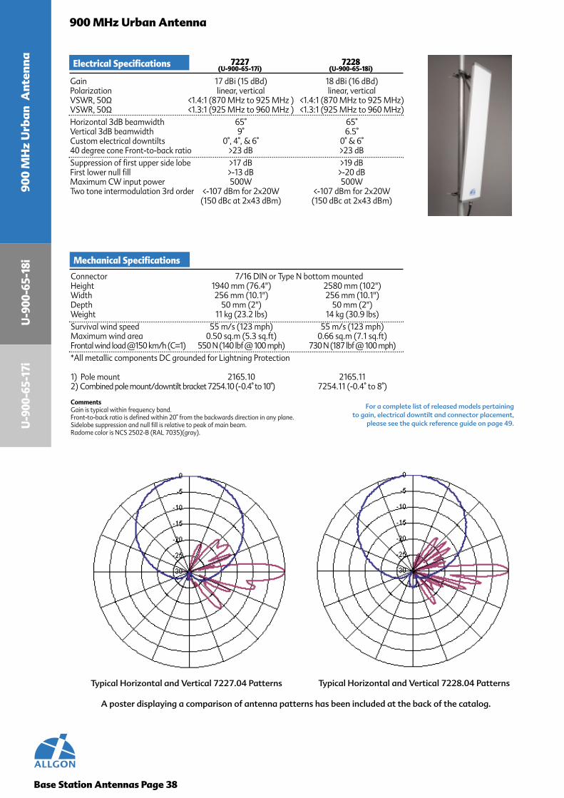
Typical Horizontal and Vertical 7227.04 Patterns Typical Horizontal and Vertical 7228.04 Patterns
Electrical Specifications 7227 7228(U-900-65-17i) (U-900-65-18i)
Gain 17 dBi (15 dBd) 18 dBi (16 dBd)Polarization linear, vertical linear, verticalVSWR, 50Ω <1.4:1 (870 MHz to 925 MHz ) <1.4:1 (870 MHz to 925 MHz)VSWR, 50Ω <1.3:1 (925 MHz to 960 MHz ) <1.3:1 (925 MHz to 960 MHz)Horizontal 3dB beamwidth 65° 65°Vertical 3dB beamwidth 9° 6.5°Custom electrical downtilts 0°, 4°, & 6° 0° & 6°40 degree cone Front-to-back ratio >23 dB >23 dBSuppression of first upper side lobe >17 dB >19 dBFirst lower null fill >-13 dB >-20 dBMaximum CW input power 500W 500WTwo tone intermodulation 3rd order <-107 dBm for 2x20W <-107 dBm for 2x20W
(150 dBc at 2x43 dBm) (150 dBc at 2x43 dBm)
Mechanical Specifications
Connector 7/16 DIN or Type N bottom mountedHeight 1940 mm (76.4") 2580 mm (102")Width 256 mm (10.1") 256 mm (10.1")Depth 50 mm (2") 50 mm (2")Weight 11 kg (23.2 lbs) 14 kg (30.9 lbs)Survival wind speed 55 m/s (123 mph) 55 m/s (123 mph)Maximum wind area 0.50 sq.m (5.3 sq.ft) 0.66 sq.m (7.1 sq.ft)Frontal wind load @150 km/h (C=1) 550 N (140 lbf @ 100 mph) 730 N (187 lbf @ 100 mph)*All metallic components DC grounded for Lightning Protection
1) Pole mount 2165.10 2165.112) Combined pole mount/downtilt bracket 7254.10 (-0.4° to 10°) 7254.11 (-0.4° to 8°)
CommentsGain is typical within frequency band.Front-to-back ratio is defined within 20° from the backwards direction in any plane.Sidelobe suppression and null fill is relative to peak of main beam.Radome color is NCS 2502-B (RAL 7035)(gray).

Base Station Antennas Page 39
900 MHz Urban Antenna
A poster displaying a comparison of antenna patterns has been included at the back of the catalog.
Typical Horizontal and Vertical 7230.04 Patterns Typical Horizontal and Vertical 7231.04 Patterns
For a complete list of released models pertaining to gain, electrical downtilt and connector placement,
please see the quick reference guide on page 49.
900 MH
z Urban A
ntennaU
-900-90-12i
Electrical Specifications 7230 7231(U-900-90-12i) (U-900-90-14i)
Gain 12 dBi (10 dBd) 14 dBi (12 dBd)Polarization linear, vertical linear, verticalVSWR, 50Ω <1.4:1 (870 MHz to 925 MHz) <1.4:1 (870 MHz to 925 MHz)VSWR, 50Ω <1.3:1 (925 MHz to 960 MHz) <1.3:1 (925 MHz to 960 MHz)Horizontal 3dB beamwidth 90° 90°Vertical 3dB beamwidth 27° 14°Custom electrical downtilts 0° 0° & 6°40 degree cone Front-to-back ratio >20 dB >20 dBSuppression of first upper side lobe >12 dB >15 dBMaximum CW input power 300W 500WTwo tone intermodulation 3rd order <-107 dBm for 2x20W <-107 dBm for 2x20W
(150 dBc at 2x43 dBm) (150 dBc at 2x43 dBm)
Mechanical Specifications
Connector 7/16 DIN or Type N bottom mountedHeight 695 mm (27.4") 1320 mm (52")Width 160 mm (6.3") 160 mm (6.3")Depth 55 mm (2.2") 55 mm (2.2")Weight 3 kg (6.6 lbs) 6 kg (13.2 lbs)Survival wind speed 55 m/s (123 mph) 55 m/s (123 mph)Maximum wind area 0.11 sq.m (1.2 sq.ft) 0.21 sq.m (2.3 sq.ft)Frontal wind load @150 km/h (C=1) 120 N (31.4 lbf @ 100 mph) 230 N (74.9 lbf @ 100 mph)*All metallic components DC grounded for Lightning Protection
1) Pole mount 2165.10 2165.102) Combined pole mount/downtilt bracket 7254.10 (-1.3° to 31°) 7254.10 (-0.6° to 15°)
CommentsGain is typical within frequency band.Front-to-back ratio is defined within 20° from the backwards direction in any plane.Sidelobe suppression and null fill is relative to peak of main beam.Radome color is NCS 2502-B (RAL 7035)(gray).
U-900-90-14i

U-9
00-9
0-16
.5i
Base Station Antennas Page 40
900 MHz Urban Antenna
A poster displaying a comparison of antenna patterns has been included at the back of the catalog.
For a complete list of released models pertaining to gain, electrical downtilt and connector placement,
please see the quick reference guide on page 49.
900
MH
z U
rban
Ant
enna
U-9
00-9
0-15
i
Typical Horizontal and Vertical 7232.04 Patterns Typical Horizontal and Vertical 7233.04 Patterns
Electrical Specifications 7232 7233(U-900-90-15i) (U-900-90-16.5i)
Gain 15 dBi (13 dBd) 16.5 dBi (14.5 dBd)Polarization linear, vertical linear, verticalVSWR, 50Ω <1.4:1 (870 MHz to 925 MHz) <1.4:1 (870 MHz to 925 MHz)VSWR, 50Ω <1.3:1 (925 MHz to 960 MHz) <1.3:1 (925 MHz to 960 MHz)Horizontal 3dB beamwidth 90° 90°Vertical 3dB beamwidth 9° 6.5°Custom electrical downtilts 0° 0° & 6°40 degree cone Front-to-back ratio >20 dB >20 dBSuppression of first upper side lobe >15 dB >17 dBFirst lower null fill >-15 dB N/AMaximum CW input power 500W 500WTwo tone intermodulation 3rd order <-107 dBm for 2x20W <-107 dBm for 2x20W
(150 dBc at 2x43 dBm) (150 dBc at 2x43 dBm)
Mechanical Specifications
Connector 7/16 DIN or Type N bottom mountedHeight 1940 mm (76.4") 2580 mm (102")Width 160 mm (6.3") 160 mm (6.3")Depth 55 mm (2.2") 55 mm (2.2")Weight 9 kg (19.8 lbs) 11 kg (23.2 lbs)Survival wind speed 55 m/s (123 mph) 55 m/s (123 mph)Maximum wind area 0.31 sq.m (3.3 sq.ft) 0.41 sq.m (4.4 sq.ft)Frontal wind load @150 km/h (C=1) 340 N (87.8 lbf @ 100 mph) 450 N (117 lbf @ 100 mph)*All metallic components DC grounded for Lightning Protection
1) Pole mount 2165.10 2165.112) Combined pole mount/downtilt bracket 7254.10 (-0.4° to 10°) 7254.11 (-0.4° to 8°)
CommentsGain is typical within frequency band.Front-to-back ratio is defined within 20° from the backwards direction in any plane.Sidelobe suppression and null fill is relative to peak of main beam.Radome color is NCS 2502-B (RAL 7035)(gray).

900 MHz Omnidirectional Antenna
Features
• Extremely rugged
• Minimized tip deflector
• Feed path yields consistent RF path and IM performance
• Able to manage high wind speeds
• Good power handling
• No hygroscopic materials
• Easily adaptive to customer requirements
• Electrical downtilt available
Design Philosophy
Our Omnidirectional antenna is designed in arepeatable procedure which requires no tuning ormodification, with the specification being the samefrom product to product. The Omni has a some-what larger diameter allowing room for individualfeed of the radiating elements, easy control of theamplitude and phase, and cables of sufficientdimensions for the current. Also, the larger diameterallows for the extruded internal support pipe whichgives the Omni its robust and rigid design, a greatersurvival wind speed, and allows for a radome ofextruded PVC plastics, thus avoiding fiberglass.
The Omni antenna is designed to provide goodpower handling with low intermodulation. It cansurvive in wind speed of 156 mph, and also haslow deflection of <1° at 156 mph wind speed.
Performance
Bracket hardware for the Omni is made of onlythe highest quality acid-proof stainless steel andis available in non-tilt mounting to a pipe. Foradditional information, see page 53.
Brackets
Base Station Antennas Page 41
Allgon prides itself on stringent testing require-ments with conservative, yet realistic claims ofthe performance of our product offering. Formore information on testing procedures, seepage 54.
Testing
7/16 DIN Connector, Type “N” Connector
Connectors
Proper use of materials and their structureensures performance integrity. In antennas, theelectrical performance is directly related tomechanical performance. The choice of radomematerial is crucial since it acts as a windowbetween the radiating elements and thecoverage area. The Omni antenna is made ofsilverplated brass with an allydyne treatment toresist corrosion. Also, the dielectric insulators aremade of teflon. Our UV stabilized PVC radome isresistant to moisture absorption and can with-stand mechanical stresses, even at low tempera-tures and long exposure to UV radiation.
Quality Materials
900 MH
z Om
nidirectional A
ntenna

Base Station Antennas Page 42
QUICK REFERENCE GUIDE
900 MHz Omni ElectricalDowntilt Inverted Mount
Gain Part Number Description Page
11 dBi
4168.11.33.52 O-900-360-11i-2-D-U 434168.11.05.52 O-900-360-11i-2-N-U 434168.11.33.53 O-900-360-11i-3-D-U 434168.11.05.53 O-900-360-11i-3-N-U 43
900 MHz Omni
Gain Part Number Description Page
11 dBi
4168.11.33.00 O-900-360-11i-0-D 434168.11.05.00 O-900-360-11i-0-N 434168.11.33.02 O-900-360-11i-2-D 434168.11.05.02 O-900-360-11i-2-N 434168.11.33.03 O-900-360-11i-3-D 434168.11.05.03 O-900-360-11i-3-N 434168.11.33.06 O-900-360-11i-6-D 434168.11.05.06 O-900-360-11i-6-N 43
900 MHzOmnidirectional
Antenna
O - 9 0 0 - 3 6 0 - 1 1 i - 0 - D7/16 DINConnector
Description Detail:
OmniFamily
FrequencyBand
HorizontalBeamwidth
Electrical DowntiltAngleGain
in dBi
900
MH
z O
mni
dire
ctio
nal A
nten
na
Antennas may be ordered using part number or description.

Base Station Antennas Page 43
900 MHz Omnidirectional Antenna
A poster displaying a comparison of antenna patterns has been included at the back of the catalog.
Typical Horizontal and Vertical 4168.11 Patterns
For a complete list of released models pertaining to gain, electrical downtilt and mounting orientation,
please see the quick reference guide on page 55.
900 MH
z Om
nidirectional A
ntenna
Electrical Specifications 4168.11(O-900-360-11i)
Gain 11 dBi (9 dBd)Polarization linearVSWR, 50Ω <1.3:1 (925 MHz to 960 MHz), 1.5:1 (925 MHz to 960 MHz)Horizontal 3dB beamwidth 360°Vertical 3dB beamwidth 6.5°Custom electrical downtilts 0°, 2°, 3°, 6°, +2°, & +3°Maximum CW input power 500WTwo tone intermodulation 3rd order <-103 dBm for 2x20W
(146 dBc at 2x43 dBm)
Mechanical Specifications
Connector 7/16 DIN or Type N bottom mount/inverted mountHeight 3000 mm (118.1")Diameter 78 mm (3.1")Weight 11 kg (30.2 lbs)Survival wind speed 70 m/s (156 mph)Maximum wind area 0.25 sq.m (2.7 sq.ft)Frontal wind load @112mph 300 N (56 lbf)
*All metallic components DC grounded for Lightning Protection
CommentsGain is typical within frequency band.Front-to-back ratio is defined within 20° from the backwards direction in any plane.Sidelobe suppression and null fill is relative to peak of main beam.Radome color is NCS 2502-B (RAL 7035)(gray).
U-800-360-11i

Indoo
r Panel Antenna
Indoor Panel Antenna
Base Station Antennas Page 44
Features
• Perfect for indoor coverage
• Sleek design
• Easy to install
• Feed path yields consistent RF path and IM performance
• Easily adaptive to customer requirements
Design Philosophy
Our Indoor panel antenna is designed in a repeatableprocedure which requires no tuning or modification,with the specification being the same from productto product. The Indoor panel antenna is designed toblend into a wall or roof inside a building.
The Indoor panel antenna is designed for goodaesthetics with a very low profile. The depth is only1.6 inches.
Performance
Bracket hardware for the Indoor panel antenna isfor mounting to a wall inside a building. It ismade for easy installation.
Brackets
Allgon prides itself on stringent testing require-ments with conservative, yet realistic claims of theperformance of our product offering. The antennais tested for VSWR, intermodulation, powerhandling and gain.
Testing
Type “N” Connector, SMA
Connectors
Proper use of materials and their structure ensuresperformance integrity. In antennas, the electricalperformance is directly related to mechanicalperformance. The choice of radome material iscrucial since it acts as a window between theradiating elements and the coverage area. TheIndoor panel antenna is made with aircraft qualityaluminum. Also, the dielectric insulators are madeof teflon. Our UV stabilized PVC radome is verysleek and thin for an indoor environment.
Quality Materials

Base Station Antennas Page 45
QUICK REFERENCE GUIDE
Multiband (800 MHz/900 MHz/1800MHz/1900 MHz/2100 MHz) Omni
Gain Part Number Description Page3 dBi 7336.00 ALIC-8/9/18/19/2100-360-3i-O-N 46
1800/1900 MHz Panel
Gain Part Number Description Page10 dBi 7193.01 CO-1800/1900-65-10i-O-N 46
900 MHz Panel
Gain Part Number Description Page8.5 dBi 7191.01 CO-900-74-8.5i-O-S 46
IndoorPanel
Antenna
C O - 9 0 0 - 7 4 - 8 . 5 i - 0 - SSMAConnector
Description Detail:
IndoorPanelFamily
FrequencyBand
HorizontalBeamwidth
Electrical DowntiltAngleGain
in dBi
Indo
or
Pane
l Ant
enna
Antennas may be ordered using part number or description.
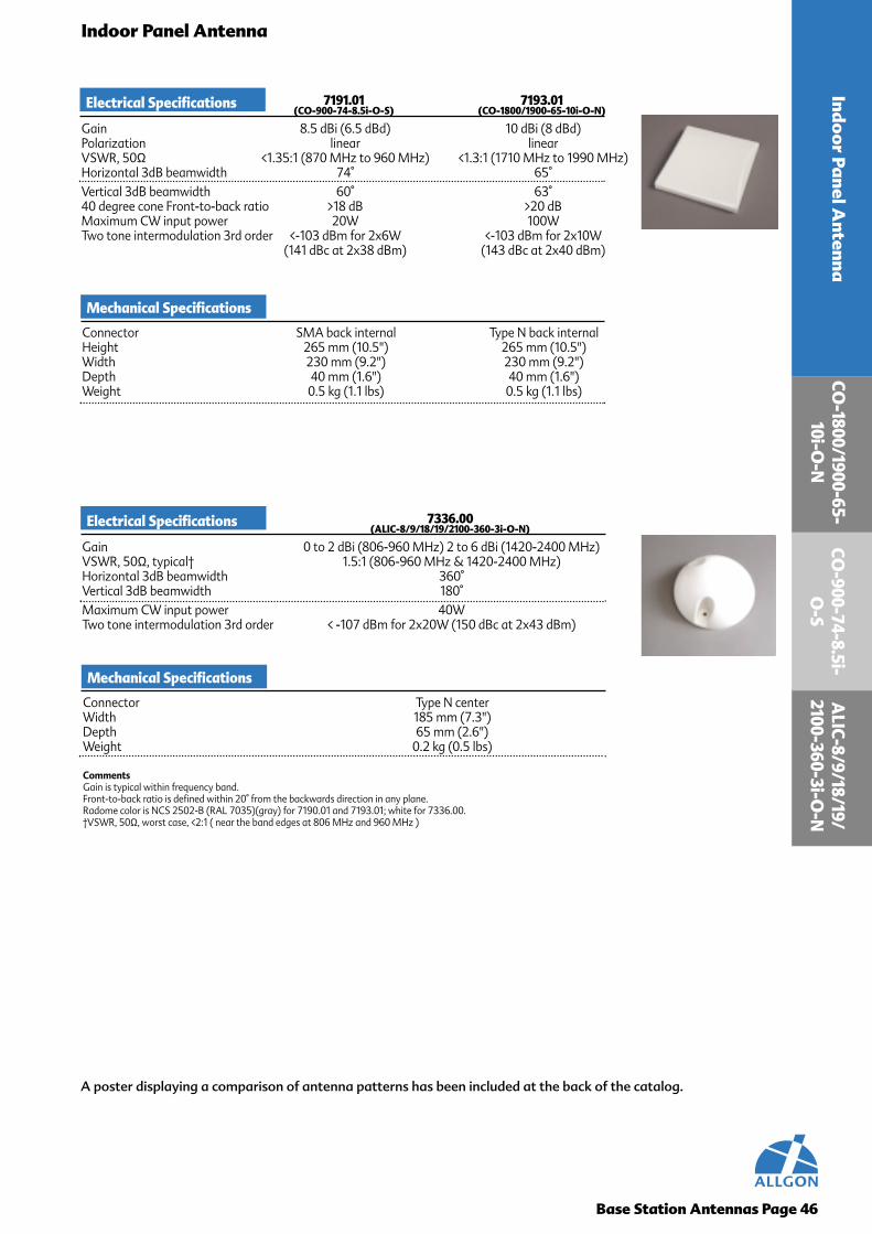
CO-1800/1900-65-
10i-O-N
ALIC-8/9/18/19/
2100-360-3i-O-N
Base Station Antennas Page 46
Indoor Panel Antenna
A poster displaying a comparison of antenna patterns has been included at the back of the catalog.
Indoo
r Panel Antenna
Electrical Specifications 7191.01 7193.01(CO-900-74-8.5i-O-S) (CO-1800/1900-65-10i-O-N)
Gain 8.5 dBi (6.5 dBd) 10 dBi (8 dBd)Polarization linear linearVSWR, 50Ω <1.35:1 (870 MHz to 960 MHz) <1.3:1 (1710 MHz to 1990 MHz)Horizontal 3dB beamwidth 74° 65°Vertical 3dB beamwidth 60° 63°40 degree cone Front-to-back ratio >18 dB >20 dBMaximum CW input power 20W 100WTwo tone intermodulation 3rd order <-103 dBm for 2x6W <-103 dBm for 2x10W
(141 dBc at 2x38 dBm) (143 dBc at 2x40 dBm)
Mechanical Specifications
Connector SMA back internal Type N back internalHeight 265 mm (10.5") 265 mm (10.5")Width 230 mm (9.2") 230 mm (9.2")Depth 40 mm (1.6") 40 mm (1.6")Weight 0.5 kg (1.1 lbs) 0.5 kg (1.1 lbs)
Electrical Specifications 7336.00(ALIC-8/9/18/19/2100-360-3i-O-N)
Gain 0 to 2 dBi (806-960 MHz) 2 to 6 dBi (1420-2400 MHz)VSWR, 50Ω, typical† 1.5:1 (806-960 MHz & 1420-2400 MHz)Horizontal 3dB beamwidth 360°Vertical 3dB beamwidth 180°Maximum CW input power 40WTwo tone intermodulation 3rd order < -107 dBm for 2x20W (150 dBc at 2x43 dBm)
Mechanical Specifications
Connector Type N centerWidth 185 mm (7.3")Depth 65 mm (2.6")Weight 0.2 kg (0.5 lbs)
CommentsGain is typical within frequency band.Front-to-back ratio is defined within 20° from the backwards direction in any plane.Radome color is NCS 2502-B (RAL 7035)(gray) for 7190.01 and 7193.01; white for 7336.00.†VSWR, 50Ω, worst case, <2:1 ( near the band edges at 806 MHz and 960 MHz )
CO-900-74-8.5i-
O-S

Allgon DualbandFilter
Allgon DualbandFilter
900 MHz BTS 1800 MHz BTS
Tower Top
Inside theShelter
AllgonDualbandAntenna
FeederCables
22 AANNTTEENNNNAASS PPEERR SSEECCTTOORR FFAACCEE11 AANNTTEENNNNAA PPEERR SSEECCTTOORR FFAACCEE
Allgon DualbandFilter
1800 MHz BTS900 MHz BTS
900MHzDual
PolarizedAntenna
1800MHzDual
PolarizedAntenna
Tower Top
Inside theShelter
Allgon DualbandFilter
Allgon DualbandFilter
Allgon DualbandFilter
Feeder Cables
Base Station Antennas Page 47

900/1800 MH
z Dualband So
lution
900/1800 MHz Dualband Solution
Base Station Antennas Page 48
Features
• Stable pattern across eachfrequency band
• 100% IM testing
• Superior vertical pattern shapingfor interference reduction
• 100% verified for vertical patternperformance
• Mechanical design allows forthermal expansion
• Aesthetically pleasing
Installation Advantages
• Save cash on cable
• Reduce wind load on theinstallation
• Reduce weight
Design
The Allgon dualband antennas utilize adualband feed network to excite the dual-band radiating elements. Allgon dualbandantennas and dualband filters can be usedtogether or seperately, to halve thenumber of feeder cables at your site. Thisminimizes total hardware at your site.
Utilize the existing two feeder cables persector face to deploy 1800 MHzcoverage. Or, for new 900 MHzinstallation, this practice allows for future1800 MHz deployment without anothertower climb. Using a dualband dualpolarized antenna allows for one antennaper sector face to avoid aestheticcriticism. Using two dual polarized singleband antennas per sector face, you stillonly need two feeder cables per sector.The two antennas per sector face allowfor ease of mechanical downtiltoptimization between bands. With eitherdesign practice, space-leasing costs anddeployment costs are kept to a minimumand overall tower loading is minimizedwith virtually any wireless installation.
Benefits

Base Station Antennas Page 49
QUICK REFERENCE GUIDE
65° Maximum Gain Dualband Panel
DualbandAntenna
A L X C - 9 0 0 / 1 8 0 0 - 6 5 - 1 5 . 5 / 1 7 . 5 i - 0 - D
Description Detail:
AllgonCross-PolarizedCombined
FrequencyBands
HorizontalBeamwidth
7/16 DIN Connector
Gainin dBi900 MHz
Gainin dBi1800 MHz
ElectricalDowntiltAngle
900/
1800
MH
z D
ualb
and
Solu
tio
n
Antennas may be ordered using part number or description.
Gain Part Number Description Page
65° Equal Beamwidth Dualband Panel
Gain Part Number Description Page
15.5 dBi17.5 dBi
7330.00 ALXC-900/1800-65-15.5/17.5i-0-D 507330.01 ALXC-900/1800-65-15.5/17.5i-1-D 507330.02 ALXC-900/1800-65-15.5/17.5i-2-D 507330.03 ALXC-900/1800-65-15.5/17.5i-3-D 507330.04 ALXC-900/1800-65-15.5/17.5i-4-D 507330.05 ALXC-900/1800-65-15.5/17.5i-5-D 507330.06 ALXC-900/1800-65-15.5/17.5i-6-D 50
16.5 dBi16 dBi
7331.00 ALXC-900/1800-65-16.5/16i-0-D 517331.01 ALXC-900/1800-65-16.5/16i-1-D 517331.02 ALXC-900/1800-65-16.5/16i-2-D 517331.03 ALXC-900/1800-65-16.5/16i-3-D 517331.04 ALXC-900/1800-65-16.5/16i-4-D 517331.05 ALXC-900/1800-65-16.5/16i-5-D 517331.06 ALXC-900/1800-65-16.5/16i-6-D 51
Dualband Filter
Part Number Page9215.01 52

Connector 7/16 DIN bottom mountedHeight 1450 mm (53.1")Width 280 mm (11")Depth 125 mm (4.9")Weight 10.8 kg (20.7 lbs)Survival wind speed 70 m/s (156 mph)Maximum wind area 0.41 sq.m (4.1 sq.ft)Frontal wind load @150 km/h (C=1) 450 N (107 lbf)
*All feed network components DC grounded for Lightning Protection
Mounting Hardware Options for Installation1) Pole mount 2165.102) Combined pole mount and downtilt bracket 7254.10 (-0.6° to 15°)
CommentsGain is typical within frequency band.Beamwidths are defined using total power.Cross-polar discrimination is defined within -3 dB beamwidth.Front-to-back ratio is defined within 20° from the backwards direction in any plane.Sidelobe suppression and null fill is relative to peak of main beam.Maximum input power is total input power, divided arbitrarily between inputs.Radome color is NCS 2502-B (RAL 7035)(gray).
ALX
C-900/1800-65-15.5/17.5i
Base Station Antennas Page 50
900/1800 MHz Dualband Antenna
A poster displaying a comparison of antenna patterns has been included at the back of the catalog.
For a complete list of released modelspertaining to gain and electrical downtilt,
please see the quick reference guide onpage 62.
900/1800 MH
z Dualband A
ntenna
Preliminary Electrical Specifications 7330(ALXC-900/1800-65-15.5/17.5i)
Gain 15.5 dBi (13.5 dBd) 870 to 960 MHz17.5 dBi (15.5 dBd) 1710 to 1880 MHz
Polarization slant 45VSWR, 50Ω <1.5:1 RX, <1.3:1 TXHorizontal 3dB beamwidth 65°Vertical 3dB beamwidth 13° (870 MHz-960 MHz)
7° (1710 MHz-1880 MHz)Custom electrical downtilts 0°, 1°, 2°, 3°, 4°, 5° & 6° (same tilt angle for both bands)Suppression of first upper side lobe >16 dBFirst lower null fill >-20 dB (870 to 960 MHz)
>-18 dB (1710 to 1880 MHz)Maximum CW input power, 300W per port 600W (total)Cross polar discrimination 11 dBFront to back ratio >26 dB co-polar, > 22 dB total powerTwo tone intermodulation 3rd order (900 MHz) <-107 dBm for 2x20 W
(150 dBc at 2x43 dBm )Two tone intermodulation 3rd order (1800 MHz) <-110 dBm for 2x10 W
(150 dBc at 2x40 dBm)
Preliminary Mechanical Specifications
Typical Horizontal and Vertical 7330.00 Patterns at 1800 MHz
Typical Horizontal and Vertical 7330.00 Patterns at 900 MHz
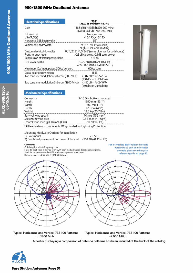
Connector 7/16 DIN bottom mountedHeight 1990 mm (53.1")Width 280 mm (11")Depth 125 mm (4.9")Weight 13.5 kg (20.7 lbs)Survival wind speed 70 m/s (156 mph)Maximum wind area 0.56 sq.m (4.1 sq.ft)Frontal wind load @150km/h (C=1) 610 N (107 lbf)*All feed network components DC grounded for Lightning Protection
Mounting Hardware Options for Installation1) Pole mount 2165.102) Combined pole mount and downtilt bracket 7254.10 (-0.4° to 10°)
CommentsGain is typical within frequency band.Front-to-back ratio is defined within 20° from the backwards direction in any plane.Sidelobe suppression and null fill is relative to peak of main beam.Radome color is NCS 2502-B (RAL 7035)(gray)
ALX
C-90
0/18
00-
65-1
6.5/
16i
Base Station Antennas Page 51
900/1800 MHz Dualband Antenna
A poster displaying a comparison of antenna patterns has been included at the back of the catalog.
900/
1800
MH
z D
ualb
and
Ant
enna
Electrical Specifications 7331(ALXC-65-900/1800-16.5/16i)
Gain 16.5 dBi (14.5 dBd) 870-960 MHz16 dBi (14 dBd) 1710-1880 MHz
Polarization linear, verticalVSWR, 50Ω <1.5:1 RX, <1.3:1 TXHorizontal 3dB beamwidth 65°Vertical 3dB beamwidth 9° (870 MHz-960 MHz)
9° (1710 MHz-1880 MHz)Custom electrical downtilts 0°, 1°, 2°, 3°, 4°, 5° & 6° (same tilt angle for both bands)Front-to-back ratio > 25 dB co-polar, > 21 dB total powerSuppression of first upper side lobe > 16 dBFirst lower null fill > -22 dB (870 to 960 MHz)
> -22 dB (1710 MHz-1880 MHz)Maximum CW input power, 300W per port 600W totalCross-polar discrimination 11 dBTwo tone intermodulation 3rd order (900 MHz) <-107 dBm for 2x20 W
(150 dBc at 2x43 dBm)Two tone intermodulation 3rd order (1800 MHz) <-110 dBm for 2x10 W
(150 dBc at 2x40 dBm)
Mechanical Specifications
For a complete list of released modelspertaining to gain and electrical
downtilt, please see the quickreference guide on page 62.
Typical Horizontal and Vertical 7331.00 Patterns at 1800 MHz
Typical Horizontal and Vertical 7331.00 Patterns at 900 MHz

Connector 7/16 DIN plug all three portsHeight 2" (50 mm)Width 7.5" (190 mm)Depth 2.4" (60 mm) excluding connectorsWeight 3.1 lbs (1.4 kg)Housing IP 68Temperature Range, Operational -40°C to +70°CTemperature Range, Storage -45°C to +85°C
Dual Band Filter Page 52
900/1800 MHz Dualband Filter900/1800 M
Hz D
ualband Filter
Preliminary Electrical Specifications 9215.01
Frequency Range 872-960 MHz and 1710-1880 MHzIsolation > 50 dB between the single band portsInsertion Loss < 0.2 dBReturn Loss > 20 dB all portsMaximum Average Power 300 W @ 900 MHz, 150 W @ 1800 MHzTypical Maximum Average Combined Power 150 W @ 900 MHz, 75 W @ 1800 MHzTwo tone intermodulation 3rd order < -110 dBm for 2x20W (153 dBc at 2x43 dBm)Lightning Protection IEC 1312-1 and IEC 1000-4-5Note: Electrical specifications for normal operating conditions and with an antenna Return Loss betterthan 14 dB, 1.5:1 VSWR.
Preliminary Mechanical Specifications

Mo
unting Brackets
Mounting Brackets
Allgon Mounting Brackets are made with only the highest quality acid proof stainless steel. They will easilywithstand the most severe environments.
The tilt and panning sets are designed to be used as an integral part of the antenna. The end caps of each antennaare design to mount directly to the panning or tilting bracket without the use of intermediate parts. This simplifieddesign gives ease of use as well as increased performance and reliability. The performance of our mountingconfigurations and settings, including panning and tilting brackets, are verified through vibration testing.
Our Antennas can be mounted in three ways:1. Vertically, using heavy-duty clamps2. Vertically, using heavy-duty clamps and tilt brackets3. Vertically, using heavy-duty clamps, panning brackets and tilt brackets
Base Station Antennas Page 53
Bracket Options
Bracket Type2165.102165.117254.107254.112201.102201.112190.10
2187.0000
Pole/Wall bracket for 2 mounting pointsPole/Wall bracket for 3 mounting pointsCombined pole mount and tilt bracket for 2 mounting pointsCombined pole mount and tilt bracket for 3 mounting pointsPanning bracket for 2165.10 and 7254.10Panning bracket for 2165.11 and 7254.11Hose clamp kit for pole diameter 40-100Upside-down kit for Omni
2201.10 & 7254.10 2165.10 7254.10
7254.10 Omni Mounting 7254.10

Testing Procedures
Performance
Reliability
Allgon prides itself on stringent testing requirements with conservative, yet realistic claims of the performance of ourproduct offering. Our antennas are evaluated on performance and reliability.
Electrical performance can be subdivided into a set of parameters/tests that characterizes the antennas ability tofunction well; however, good performance is also the sign of good quality and that a lot of effort has been put into the an-tenna at the design stage. Every Allgon antenna is verified with the following list of parameters:
Radiation PatternHorizontal Beamwidth Electrical tilt angleElevational beamwidth Front-to-Back RatioFirst upper sidelobe suppression First null fill below horizon
Intermodulation ProductsGainPower HandlingReturn LossLightning ProtectionDurability
The mechanical stability of an antenna directly effects its electrical performance, therefore our antennas are designed towithstand the harshest conditions and still perform appropriately. Allgon antennas are mechanically verified by the fol-lowing sequence:
Vibration IEC 68-2-2, test Fc, 5-150 Hz, displacement +0.5 mm or 2 g, 1 octave/min, 1.5 hours atresonance frequency, test in three directions
Coldness IEC 68-2-1, test Ab, 16 hours at -55°C +3°CHeat IEC 68-2-2, test Bb, 16 hours at +75°C +2°CTemperatureChanges IEC 68-2-14, test Nb, -40°C+ 2°C to + 70°C+ 5°C, 10 cycles at 2+2 hoursSalt Mist IEC 68-2-11, test Ka, neutral salt mist for 96 hoursHumidity IEC 68-2-30, test Db, 10 cycles at 24 hours in 90% - 98% rel. humidity at 25°C +3°C to
40°C +2°CRain IEC 68-2-18 , test Rb 2.2, 30 min, 60° spray angleUV Radiation IEC 68-2-5, test Sa, procedure C, 56 days at + 40°CInput Power input power 200 W for 1 hourLightningProtection LEMP test with 100 kV/m field strength, 1.2/50 µs pulse. Current discharge with 170 kA
peak current.Drop 6 drop tests from 41 cm and 4 drop tests from 56 cm onto a flat steel surface. The 41 cm
drops are oriented onto edges and corners in 10 angles. The 56 cm drops are orientedwith point of equilibrium straight about the point of impact. No damage allowed onproduct.
Compression Load between two plane-parallel plates at 3 sides. The load is 7.0 kN, 5.1 kN and 0.4 kNon sides according to size, without damages on the product.
Vibration 120 min. random vibration in two axes simultaneously at a calibrated acceleration of 1.0 g. Frequency range 1-64 Hz. One hour in main direction and two other directions. Nodamage allowed on the product.
Shock 8 impacts in the horizontal direction. Acceleration 7.5 g, pulse 50 µs. No damage al-lowed on the product.
Base Station Antennas Page 54
Test
ing
Pro
cedu
res

Tower To
p Am
plifierTower Top Amplifier
Tower Top Amplifier Page 55
Features
• Ultra low weight and volume
• Low noise figure
• Customer adaptable band selection
• Fail safe automatic silicon based bypassand alarm
• Receive and duplex available
• Customized Alarm and Power DistributionUnit
• Optimized for Allgon Base Station Antennas
• Easy mounting
• Lightning protection
The Allgon TTA system consists of the TTA,mounted in close proximity to the antenna, and anAlarm and Power Distribution Unit (APDU)situated in or near the BTS. The APDU alsofacilitates an alarm and control function thatindicates malfunction and bypass in the TTA. TheAPDU will indicate an alarm if either one, or bothof the transistors in the LNA balanced pair has amalfunction. If one transistor fails, it is consideredas a minor alarm. If both transistors fail, it is amajor alarm and the TTA will go to bypass mode.The bypass can also be controlled manually via theAPDU front panel.
The APDU provides DC-power to six TTA’s byinjecting current onto the associated antennafeeder connected to each TTA. The supply currentis fed onto the feeders by means of the currentinjector (CI) which is placed in Receive and/orTransmit- signal path. The CI has a low loss RF-connection to the connector opposite to the cableentry on the CI. The DC-power is connected to theoutput connector, and isolated from the BTS sideof the unit. The DC-signal is low-pass filteredbefore leaving the unit at the DC-connector. The CIis also lightning protected.
System Configuration
The Allgon Tower Top Amplifier (TTA) for PCN &GSM applications, is a small and lightweightproduct intended for systems where the operatorwants to increase the sensitivity in the up-linktransmission. The TTA will enhance the systemnoise figure and, hence, make it possible either toincrease the cell site area coverage, or for theterminals to back off output power.
The TTA is especially useful in cell sites where longfeeders are used, i.e. where high cable lossdecreases the performance. The front end of theTTA is a 25 MHz receive band filter, followed by abalanced pair of Low Noise Amplifiers (LNA´s).The TTA also features an automatic bypass in caseof malfunction. The TTA is designed to withstandlightning.
Application
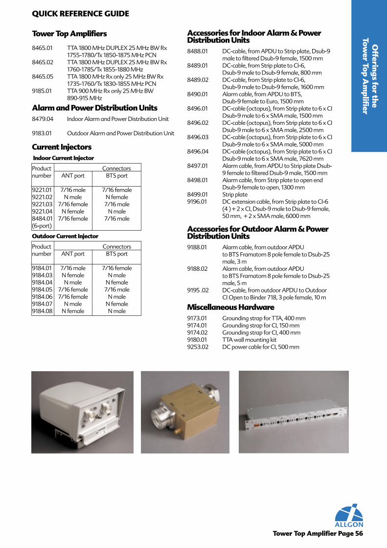
Tower Top Amplifiers
8465.01 TTA 1800 MHz DUPLEX 25 MHz BW Rx 1755-1780/Tx 1850-1875 MHz PCN
8465.02 TTA 1800 MHz DUPLEX 25 MHz BW Rx 1760-1785/Tx 1855-1880 MHz
8465.05 TTA 1800 MHz Rx only 25 MHz BW Rx 1735-1760/Tx 1830-1855 MHz PCN
9185.01 TTA 900 MHz Rx only 25 MHz BW 890-915 MHz
Alarm and Power Distribution Units8479.04 Indoor Alarm and Power Distribution Unit
9183.01 Outdoor Alarm and Power Distribution Unit
Current InjectorsIndoor Current Injector
Product Connectorsnumber ANT port BTS port
9221.01 7/16 male 7/16 female9221.02 N male N female9221.03 7/16 female 7/16 male9221.04 N female N male8484.01 7/16 female 7/16 male(6-port)
Outdoor Current Injector
Product Connectorsnumber ANT port BTS port
9184.01 7/16 male 7/16 female9184.03 N female N male9184.04 N male N female9184.05 7/16 female 7/16 male9184.06 7/16 female N male9184.07 N male N female9184.08 N female N male
Tower Top Amplifier Page 56
QUICK REFERENCE GUIDEO
fferings for the
Tower To
p Am
plifierAccessories for Indoor Alarm & PowerDistribution Units8488.01 DC-cable, from APDU to Strip plate, Dsub-9
male to filtered Dsub-9 female, 1500 mm8489.01 DC-cable, from Strip plate to CI-6,
Dsub-9 male to Dsub-9 female, 800 mm8489.02 DC-cable, from Strip plate to CI-6,
Dsub-9 male to Dsub-9 female, 1600 mm8490.01 Alarm cable, from APDU to BTS,
Dsub-9 female to Euro, 1500 mm8496.01 DC-cable (octopus), from Strip plate to 6 x CI
Dsub-9 male to 6 x SMA male, 1500 mm8496.02 DC-cable (octopus), from Strip plate to 6 x CI
Dsub-9 male to 6 x SMA male, 2500 mm8496.03 DC-cable (octopus), from Strip plate to 6 x CI
Dsub-9 male to 6 x SMA male, 5000 mm8496.04 DC-cable (octopus), from Strip plate to 6 x CI
Dsub-9 male to 6 x SMA male, 7620 mm8497.01 Alarm cable, from APDU to Strip plate Dsub-
9 female to filtered Dsub-9 male, 1500 mm8498.01 Alarm cable, from Strip plate to open end
Dsub-9 female to open, 1300 mm8499.01 Strip plate9196.01 DC extension cable, from Strip plate to CI-6
(4 ) + 2 x CI, Dsub-9 male to Dsub-9 female, 50 mm, + 2 x SMA male, 6000 mm
Accessories for Outdoor Alarm & PowerDistribution Units9188.01 Alarm cable, from outdoor APDU
to BTS Framatom 8 pole female to Dsub-25 male, 3 m
9188.02 Alarm cable, from outdoor APDUto BTS Framatom 8 pole female to Dsub-25 male, 5 m
9195 .02 DC-cable, from outdoor APDU to Outdoor CI Open to Binder 718, 3 pole female, 10 m
Miscellaneous Hardware9173.01 Grounding strap for TTA, 400 mm9174.01 Grounding strap for CI, 150 mm9174.02 Grounding strap for CI, 400 mm9180.01 TTA wall mounting kit9253.02 DC power cable for CI, 500 mm
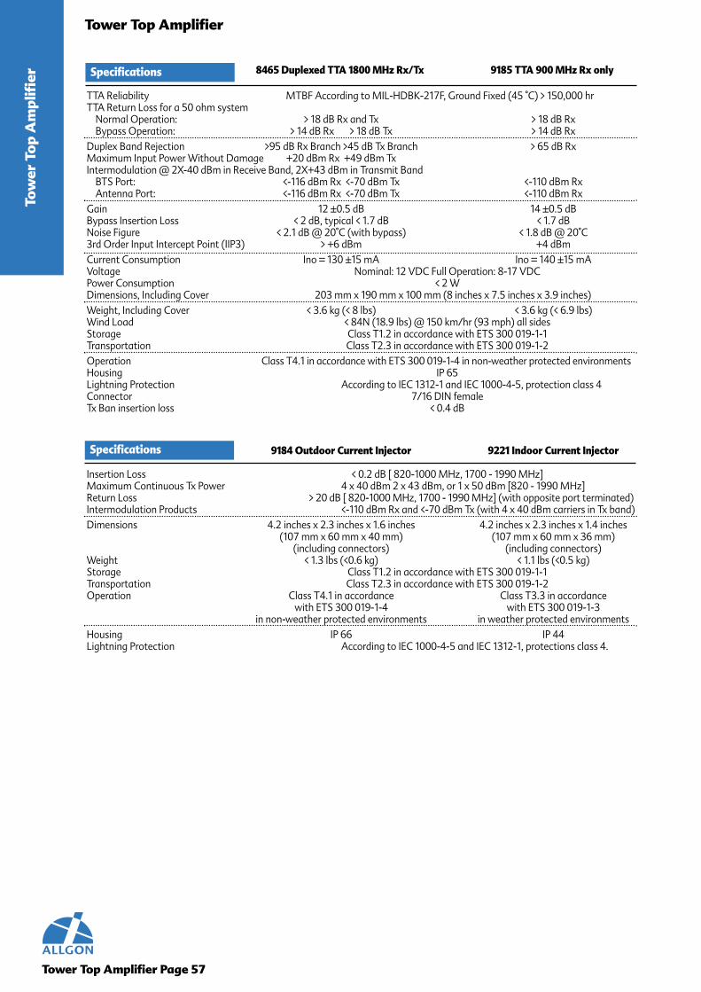
Tower Top Amplifier Page 57
Tower Top AmplifierTo
wer
To
p A
mpl
ifie
r Specifications 8465 Duplexed TTA 1800 MHz Rx/Tx 9185 TTA 900 MHz Rx only
TTA Reliability MTBF According to MIL-HDBK-217F, Ground Fixed (45 °C) > 150,000 hrTTA Return Loss for a 50 ohm system
Normal Operation: > 18 dB Rx and Tx > 18 dB RxBypass Operation: > 14 dB Rx > 18 dB Tx > 14 dB Rx
Duplex Band Rejection >95 dB Rx Branch >45 dB Tx Branch > 65 dB RxMaximum Input Power Without Damage +20 dBm Rx +49 dBm TxIntermodulation @ 2X-40 dBm in Receive Band, 2X+43 dBm in Transmit Band
BTS Port: <-116 dBm Rx <-70 dBm Tx <-110 dBm RxAntenna Port: <-116 dBm Rx <-70 dBm Tx <-110 dBm Rx
Gain 12 ±0.5 dB 14 ±0.5 dBBypass Insertion Loss < 2 dB, typical < 1.7 dB < 1.7 dBNoise Figure < 2.1 dB @ 20°C (with bypass) < 1.8 dB @ 20°C3rd Order Input Intercept Point (IIP3) > +6 dBm +4 dBmCurrent Consumption Ino = 130 ±15 mA Ino = 140 ±15 mAVoltage Nominal: 12 VDC Full Operation: 8-17 VDCPower Consumption < 2 WDimensions, Including Cover 203 mm x 190 mm x 100 mm (8 inches x 7.5 inches x 3.9 inches)Weight, Including Cover < 3.6 kg (< 8 lbs) < 3.6 kg (< 6.9 lbs)Wind Load < 84N (18.9 lbs) @ 150 km/hr (93 mph) all sidesStorage Class T1.2 in accordance with ETS 300 019-1-1Transportation Class T2.3 in accordance with ETS 300 019-1-2Operation Class T4.1 in accordance with ETS 300 019-1-4 in non-weather protected environmentsHousing IP 65Lightning Protection According to IEC 1312-1 and IEC 1000-4-5, protection class 4Connector 7/16 DIN femaleTx Ban insertion loss < 0.4 dB
9184 Outdoor Current Injector 9221 Indoor Current Injector
Insertion Loss < 0.2 dB [ 820-1000 MHz, 1700 - 1990 MHz]Maximum Continuous Tx Power 4 x 40 dBm 2 x 43 dBm, or 1 x 50 dBm [820 - 1990 MHz]Return Loss > 20 dB [ 820-1000 MHz, 1700 - 1990 MHz] (with opposite port terminated)Intermodulation Products <-110 dBm Rx and <-70 dBm Tx (with 4 x 40 dBm carriers in Tx band)Dimensions 4.2 inches x 2.3 inches x 1.6 inches 4.2 inches x 2.3 inches x 1.4 inches
(107 mm x 60 mm x 40 mm) (107 mm x 60 mm x 36 mm) (including connectors) (including connectors)
Weight < 1.3 lbs (<0.6 kg) < 1.1 lbs (<0.5 kg)Storage Class T1.2 in accordance with ETS 300 019-1-1Transportation Class T2.3 in accordance with ETS 300 019-1-2Operation Class T4.1 in accordance Class T3.3 in accordance
with ETS 300 019-1-4 with ETS 300 019-1-3in non-weather protected environments in weather protected environments
Housing IP 66 IP 44Lightning Protection According to IEC 1000-4-5 and IEC 1312-1, protections class 4.
Specifications

Tower To
p Am
plifierTower Top Amplifier
Tower Top Amplifier Page 58
9183 Outdoor Alarm 8479 Indoor Alarm and Power Distribution Unit and Power Distribution Unit
Input Voltage -20 to -70 VDC ±18 to ±72 VDCInput Current < 2 A < 2 AInput Protection Fuse, 2 A slow Reversed voltage diode protection Fuse, 2 A slow Reversed voltage diode protectionOutput Voltage 12 VDC +3 to -0.5 VDC 12 VDC +3 to -0.5 VDCOutput Protection Fuse, 500 mA slow Reverse voltage diode protection Fuse, 500 mA slow Reverse voltage diode protectionOutput Current, each DC output Normal operation: Ino =130±15 mA Normal operation: Ino =130±15 mA
One transistor fail: 180 mA <IMi < 250 mA One transistor fail: 180 mA <IMi < 250 mATwo transistor fail: IMa >250 mA Two transistor fail: IMa >250 mA
Dimensions 7.9 inches x 11.8 inches x 5.9 inches 1.7 inches x 19 inches x 6.7 inches(200 mm x 300 mm x 150 mm) (44 mm x 483 mm x 170 mm)
Weight <13.2 lbs (< 6 kg ) <5.8 lbs (< 2.6 kg)Storage Class T1.2 in accordance with ETS 300 019-1-1 Class T1.2 in accordance with ETS 300 019-1-1Transportation Class T2.3 in accordance with ETS 300 019-1-2 Class T2.3 in accordance with ETS 300 019-1-2
in non-weather protected environments in non-weather protected environmentsOperation Class T4.1 in accordance Class T3.3 in accordance
with ETS 300 019-1-4 with ETS 300 019-1-3in non-weather protected environments in weather protected environments
Housing IP 65 Mounting is designed for a standard 19 inch rack
PCN Two-Sector Site Configuration
Specifications
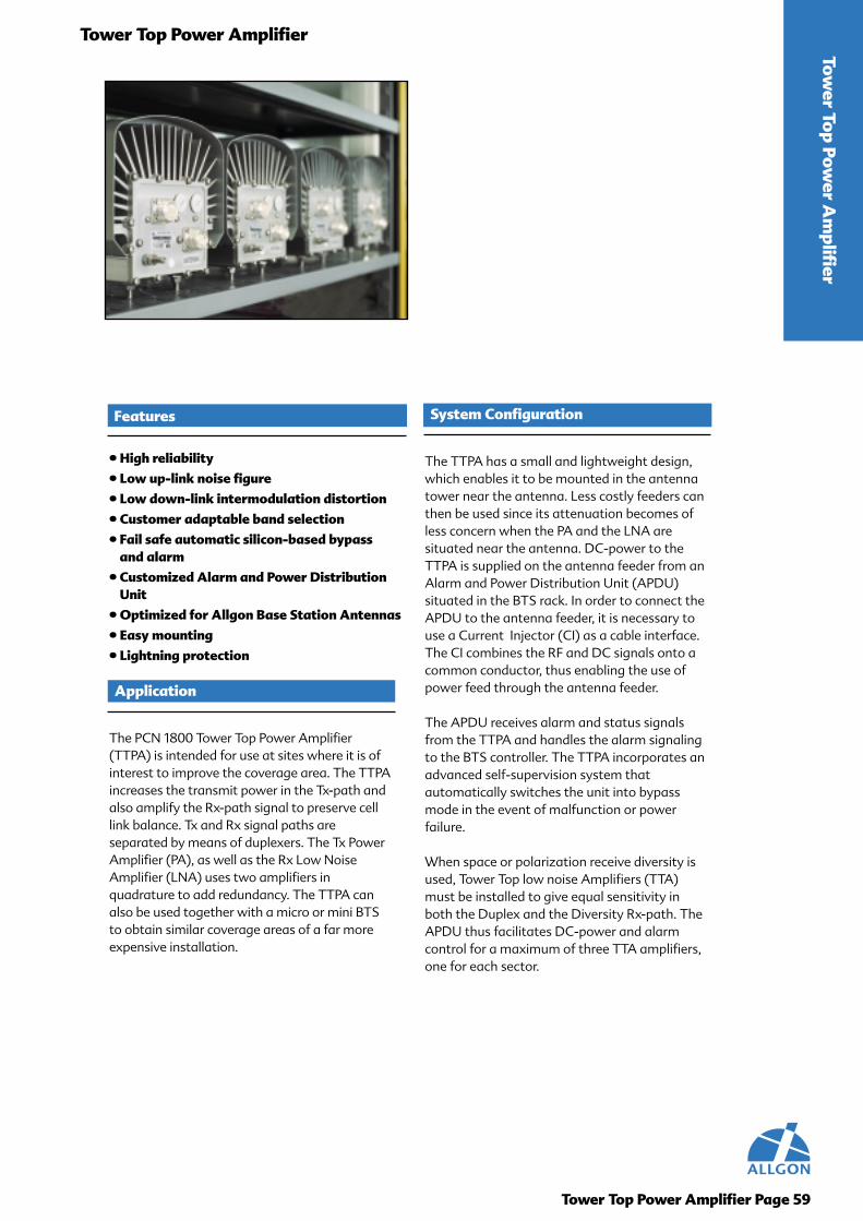
Tower To
p Power A
mplifier
Tower Top Power Amplifier
Tower Top Power Amplifier Page 59
Features
• High reliability
• Low up-link noise figure
• Low down-link intermodulation distortion
• Customer adaptable band selection
• Fail safe automatic silicon-based bypassand alarm
• Customized Alarm and Power DistributionUnit
• Optimized for Allgon Base Station Antennas
• Easy mounting
• Lightning protection
The TTPA has a small and lightweight design,which enables it to be mounted in the antennatower near the antenna. Less costly feeders canthen be used since its attenuation becomes ofless concern when the PA and the LNA aresituated near the antenna. DC-power to theTTPA is supplied on the antenna feeder from anAlarm and Power Distribution Unit (APDU)situated in the BTS rack. In order to connect theAPDU to the antenna feeder, it is necessary touse a Current Injector (CI) as a cable interface.The CI combines the RF and DC signals onto acommon conductor, thus enabling the use ofpower feed through the antenna feeder.
The APDU receives alarm and status signalsfrom the TTPA and handles the alarm signalingto the BTS controller. The TTPA incorporates anadvanced self-supervision system thatautomatically switches the unit into bypassmode in the event of malfunction or powerfailure.
When space or polarization receive diversity isused, Tower Top low noise Amplifiers (TTA)must be installed to give equal sensitivity inboth the Duplex and the Diversity Rx-path. TheAPDU thus facilitates DC-power and alarmcontrol for a maximum of three TTA amplifiers,one for each sector.
System Configuration
The PCN 1800 Tower Top Power Amplifier(TTPA) is intended for use at sites where it is ofinterest to improve the coverage area. The TTPAincreases the transmit power in the Tx-path andalso amplify the Rx-path signal to preserve celllink balance. Tx and Rx signal paths areseparated by means of duplexers. The Tx PowerAmplifier (PA), as well as the Rx Low NoiseAmplifier (LNA) uses two amplifiers inquadrature to add redundancy. The TTPA canalso be used together with a micro or mini BTSto obtain similar coverage areas of a far moreexpensive installation.
Application

Tower Top Power Amplifier Page 60
QUICK REFERENCE GUIDEO
fferings for the Tow
er Top
Power A
mplifier
Tower Top Power Amplifiers
Variant Rx Band Tx Band9251.01 1710-1735 MHz 1805-1830 MHz9251.02 1720-1745 MHz 1815-1840 MHz9251.03 1730-1755 MHz 1825-1850 MHz9251.04 1740-1765 MHz 1835-1860 MHz9251.05 1750-1775 MHz 1845-1870 MHz9251.06 1760-1785 MHz 1855-1880 MHz9251.07 1715-1740 MHz 1810-1835 MHz9251.08 1725-1750 MHz 1820-1845 MHz9251.09 1735-1760 MHz 1830-1855 MHz9251.10 1745-1770 MHz 1840-1865 MHz9251.11 1755-1780 MHz 1850-1875 MHz
Option1. External DC connector
2. External Alarm connector
3. Redundant DC/DC
Indoor/Outdoor Alarm and Power Distribution Units
9229.01 115 VAC 3-sector Alarm and Power Distribution Unit
9229.11 230 VAC 3-sector Alarm and Power Distribution Unit
Indoor/Outdoor Current Injectors
Product Number BTS-connector Antenna-connector
9254.01 7/16 DIN male 7/16 DIN female
9254.02 7/16 DIN female 7/16 DIN male
9254.03 N male N female
9254.04 N female N male

Tower Top Power Amplifier Page 61
Tower Top Power AmplifierTo
wer
To
p Po
wer
Am
plif
ier
Electrical Specifications
TTPA Reliability: The TTPA is designed to demonstrate a field proven MTBF of over 200,000 hours, calculated over a period exceeding one year.TTPA Return Loss for a 50 ohm systemBTS port: Normal operation: > 18 dB Bypass operation: > 12 dBAntenna port: Normal operation: > 18 dB Bypass operation: > 12 dBTTPA Intermodulation DistortionTwo interferer signals in the PCS-Rx band at a power level of -40 dBm at the ANT port.One interferer signal in the PCS-Tx band at a power level of +13 dBm at the ANT port.Rx measured BW 100 KHz -128 dBm ANT port -114 dBm BTS portTx measured BW 100 KHz -70 dBc ANT port -70 dBc BTS portTx Gain 7 dB ± 0.5 dBRx Gain 13 ±0.6 dBTx Bypass Loss 2.0 dB Typ. 2.6 dB Max.Rx Bypass Loss < 3.5 dBRx Input Intercept Point IIP 3 >6 dBmRx Noise Figure 2.3 dB Typ. at 25° C 2.7 dB MaxPower-on Current 5 A Max peak 3 A Max after 10 msTTPA Power Consumption Max 135 W at 43 dBm output power.Voltage Nominal: -48 VDC Full Operation: -40 to -60 VDCDimensions 350 mm x 220 mm x 230 mm (14.6 inches x 9.5 inches x 9.9 inches)Weight Amplifier and Clamping Unit 33 lbs (15 kg)Wind Load 155 N @ 150 km/h (34.4 lbs @ 93 mph)BTS and ANT Connector 7/16 DIN Female
Transport: ETS 300 019-2-2 class T2.3Storage: ETS 300 019-2-1 class T1.2Operation ETS 300 019-2-4 class T4.1 80 / 85 environmental testWeatherproofing UL50/IP 65Lightning Protection According to IEC 1000-4-5 extended to 10 kA short circuit current.UL-Recognition: UL 1950Maintenance No periodic maintenance is necessary.
9254 Current Injector Unit
Input DC Voltage (low imp. Source) -65 to +65 VDC Current 5 A maximumRF Power 56 dBm maximumInsertion Loss [820-1000 MHz, 1700 - 1990 MHz] <0.2 dBMaximum Continuous Tx Power [820 - 1990 MHz] 4 x 40 dBm, or 2 x 43 dBm, or 1 x 50 dBmIntermodulation Products (with 4 x 40 dBm carriers) < -110 dBm Rx < -70 dBm TxReturn Loss [820-1000 MHz, 1700 - 1990 MHz] > 20 dB (with opposite port terminated)Nominal Supply Voltage -48 VDCMaximum Output Voltage to/from feeder ±65 V DC (internally protected)Maximum Continuous DC-current 4.0 AMaximum Resistance in DC-path 0.4 ohmDimensions 1.6 inches x 2.4 inches x 4.2 inches (40 mm x 60 mm x 107 mm)Weight 1.4 lbs (0.6 kg)Color RAL 7035Weatherproofing IP 65
Ambient Air Temperature ETS 300 019-2-4 class T4.1 - 35 °C to + 70 °CRelative Humidity 8% to 100%Absolute Humidity 0.26 g/m3 to 30 g/m3Maximum Rate of Temperature Change 1°C/min (ambient)Air Pressure 70 kPa to 106 kPaVibration ETS 300 019-2-4Lightning Protection According to IEC 1000-4-5 and IEC 1312-1Operating Life The CI is designed for an operating life exceeding 10 years.MTBF: The TTPA is designed to demonstrate a field proven MTBF of over 200,000 hours, calculated over a period exceeding one year. UL-Recognition: UL-1950
Environmental Test Standards
Electrical Specifications
Environmental Parameters
9251 Tower Top Power Amplifier Tx/Rx

Tower To
p Power A
mplifier
Tower Top Power Amplifier
Tower Top Power Amplifier Page 62
9229 Alarm and Power Distribution Unit
AC input voltage range: 115 VAC (+6% to -10%) or 230 VAC (±10%) input, transformer-unit with overheat fuse and fused rectifier.Power Consumption
APDU Internal max: 140WTo TTPA max: 360W (400W for 10 min. duration)To TTA max: 18W
In-rush current measured at power on with nominal supply voltage:Max Peak: 50 AMax after 10 ms: 6 A
TTA Nominal Output Voltage 14 VDC (+12.8 to +15.5 VDC)
Dimensions 11.8 inches x 7.9 inches x 5.9 inches (300 mm x 200 mm x 150 mm)Weight 22 lbs (10 kg)Color RAL 7032Materials All plastic materials are characterized according to ISO 1043.Weatherproofing IP 65, providing that the valves are tighten.
Ambient Air Temperature -35°C to +55°C 40°C (air)+15°C (sun)Relative Humidity 8% to 100%Absolute Humidity 0.26 g/m3 to 30 g/m3Maximum Rate of Temperature Change 1°C/min (ambient)Air Pressure 70 kPa to 106 kPaMaximum Solar Radiation 1125 W/m2Lightning Protection The lightning protection is provided by the external Current Injectors to a level according to IEC 1312.Operating Life The APDU is designed for an operating life exceeding 10 years.MTBF The TTPA is designed to demonstrate a field proven MTBF of over 200,000 hours, calculated over a
period exceeding one year.Safety Classifications UL Recognition: UL-1950
Two-Sector Site Configuration
Electrical Performance
Mechanical Parameters
Environmental Parameters

2165.10 BRACKET KIT 2 MNTPOINTS 53
2165.11 BRACKET KIT 3 MNTPOINTS 53
2187.0000 UPSIDE-DOWN KIT OMNI 53
2190.10 HOSE CLIPS 2x40-110 53
2201.10 PANNING WALLBRACKET 2MNTPOINTS 53
2201.11 PANNING WALLBRACKET 3MNTPOINTS 53
4168.11.05.00 O-900-360-11i-0-N 43
4168.11.05.02 O-900-360-11i-2-N 43
4168.11.05.03 O-900-360-11i-3-N 43
4168.11.05.06 O-900-360-11i-6-N 43
4168.11.05.52 O-900-360-11i-2-N-U 43
4168.11.05.53 O-900-360-11i-3-N-U 43
4168.11.33.00 O-900-360-11i-0-D 43
4168.11.33.02 O-900-360-11i-2-D 43
4168.11.33.03 O-900-360-11i-3-D 43
4168.11.33.06 O-900-360-11i-6-D 43
4168.11.33.52 O-900-360-11i-2-D-U 43
4168.11.33.53 O-900-360-11i-3-D-U 43
7131.15.05.00 A-900-35-18i-0-N 21
7131.15.33.00 A-900-35-18i-0-D 21
7131.19.05.00 A-900-35-16i-0-N 21
7131.19.33.00 A-900-35-16i-0-D 21
7143.11.05.00 CI-900-60-10i-0-N 24
7143.11.33.00 CI-900-60-10i-0-D 24
7143.12.05.00 CI-900-60-13i-0-N 24
7143.12.33.00 CI-900-60-13i-0-D 24
7143.14.05.00 CI-900-60-15.5i-0-N 25
7143.14.05.50 CI-900-60-15i-A-N 33
7143.14.33.00 CI-900-60-15.5i-0-D 25
7143.14.33.50 CI-900-60-15i-A-D 33
7143.16.05.00 CI-900-60-17i-0-N 25
7143.16.33.00 CI-900-60-17i-0-D 25
7143.16.33.04 CI-900-60-17i-4-D 25
7143.16.33.06 CI-900-60-17i-6-D 25
7143.16.33.08 CI-900-60-17i-8-D 25
7143.16.33.09 CI-900-60-17i-9-D 25
7143.38.05.00 CI-900-60-18i-0-N 26
7143.38.33.00 CI-900-60-18i-0-D 26
7143.38.33.02 CI-900-60-18i-2-D 26
7143.38.33.05 CI-900-60-18i-5-D 26
7144.11.05.00 CI-900-90-8.5i-0-N 26
7144.11.33.00 CI-900-90-8.5i-0-D 26
7144.14.05.50 CI-900-90-13.5i-A-N 33
7144.14.33.00 CI-900-90-14i-0-D 27
7144.14.33.50 CI-900-90-13.5i-A-D 33
7144.16.33.00 CI-900-90-15.5i-0-D 27
7144.16.33.04 CI-900-90-15.5i-4-D 27
7144.38.33.00 CI-900-90-16.5i-0-D 28
7144.38.33.04 CI-900-90-16.5i-4-D 28
7144.38.33.05 CI-900-90-16.5i-5-D 28
7145.14.05.50 CI-900-105-13i-A-N 34
7145.14.33.00 CI-900-105-13.5i-0-D 28
7145.14.33.50 CI-900-105-13i-A-D 34
7146.12.05.00 CI-900-120-10.5i-0-N 29
7146.14.05.00 CI-900-120-13i-0-N 29
7146.14.05.50 CI-900-120-12i-A-N 34
7146.14.33.00 CI-900-120-13i-0-D 29
7146.14.33.50 CI-900-120-12i-A-D 34
7146.16.05.00 CI-900-120-14.5i-0-N 30
7146.16.33.00 CI-900-120-14.5i-0-D 30
7146.16.33.08 CI-900-120-14.5i-8-D 30
7146.38.05.00 CI-900-120-15.5i-0-N 30
7146.38.33.00 CI-900-120-15.5i-0-D 30
7146.38.33.05 CI-900-120-15.5i-5-D 30
7182.01 M-1800-65-18i-2-D 8
7182.02 M-1800-65-18i-2-D-U 8
7182.05 M-1800-65-17.5i-6-D 8
7182.06 M-1800-65-17.5i-6-D-U 8
7182.10 M-1800-65-18i-0-D 8
7183.01 M-1800-65-17i-2-D 8
7184.01 M-1800-90-16.5i-2-D 10
7185.01 M-1800-33-19.5i-2-D 6
7185.02 M-1800-33-19.5i-2-D-U 6
7187.01 M-1800-90-17.5i-2-D 10
7187.02 M-1800-90-17.5i-2-D-U 10
7187.03 M-1800-90-17.5i-4-D 10
7187.04 M-1800-90-17.5i-4-D-U 10
7191.01 CO-900-74-8.5i-0-S 46
7193.01 CO-1800/1900-65-10i-0-N 46
7194.01 M-1800-90-13.5i-6-D 9
7195.01 M-1800-65-15i-6-D 7
7195.02 M-1800-65-15i-6-D-U 7
7195.05 M-1800-65-15i-2-D 7
7198.01 M-1800-90-15.5i-2-D 9
7205.01 M-1800-65-12.5i-0-D 7
7205.02 M-1800-65-12.5i-0-D-U 7
7216.01 XU-900-65-12.5i-0-N 16
7216.03 XU-900-65-12.5i-0-D 16
7217.01 XU-900-65-15.5i-0-N 17
7217.03 XU-900-65-15i-7-D 17
7217.04 XU-900-65-15.5i-0-D 17
7217.11 XU-900-65-14.5i-9-D 17
7218.01 XU-900-65-18i-0-N 18
7218.03 XU-900-65-17.5i-6-D 18
7218.04 XU-900-65-17.5i-4-D 18
7218.05 XU-900-65-18i-0-D 18
7225.03 U-900-65-13i-0-N 37
7225.04 U-900-65-13i-0-D 37
7226.03 U-900-65-15.5i-6-D 37
7226.04 U-900-65-15.5i-0-D 37
7226.05 U-900-65-15.5i-0-N 37
7227.03 U-900-65-17i-6-D 38
7227.04 U-900-65-17i-0-D 38
7227.05 U-900-65-17i-0-N 38
7227.06 U-900-65-17i-4-D 38
7228.03 U-900-65-18i-0-N 38
7228.04 U-900-65-18i-0-D 38
7228.06 U-900-65-17.5i-6-D 38
7230.03 U-900-90-12i-0-N 39
7230.04 U-900-90-12i-0-D 39
Part Number Product Description Page Part Number Product Description Page
Index Page 63
Organized by Part Number

7231.03 U-900-90-14i-0-N 39
7231.04 U-900-90-14i-0-D 39
7231.06 U-900-90-14i-6-D 39
7232.03 U-900-90-15i-0-N 40
7232.04 U-900-90-15i-0-D 40
7232.07 U-900-90-15i-4-D 40
7233.03 U-900-90-16.5i-0-N 40
7233.04 U-900-90-16.5i-0-D 40
7233.06 U-900-90-16.5i-6-D 40
7247.03 XM-1800-65-18.5i-2-D 14
7247.04 XM-1800-65-18.5i-6-D 14
7248.02 XM-1800-90-16i-0-D 15
7254.10 TILTBRACKET 2 MNTPOINTS 53
7254.11 TILTBRACKET 3 MNTPOINTS 53
7255.01 XU-900-65-17i-0-N 17
7255.03 XU-900-65-16.5i-6-D 17
7255.04 XU-900-65-17i-0-D 17
7255.05 XU-900-65-16.5i-6-N 17
7289.02 XM-1800-65-14.5i-0-D 13
7330.00 ALXC-900/1800-65-15.5/17.5-0-D 50
7330.01 ALXC-900/1800/65-15.5/17.5i-1-D 50
7330.02 ALXC-900/1800/65-15.5/17.5i-2-D 50
7330.03 ALXC-900/1800/65-15.5/17.5i-3-D 50
7330.04 ALXC-900/1800/65-15.5/17.5i-4-D 50
7330.05 ALXC-900/1800/65-15.5/17.5i-5-D 50
7330.06 ALXC-900/1800/65-15.5/17.5i-6-D 50
7331.00 ALXC-900/1800-65-16.5/16.0i-0-D 51
7331.01 ALXC-900/1800-65-16.5/16.0i-1-D 51
7331.02 ALXC-900/1800-65-16.5/16.0i-2-D 51
7331.03 ALXC-900/1800-65-16.5/16.0i-3-D 51
7331.04 ALXC-900/1800-65-16.5/16.0i-4-D 51
7331.05 ALXC-900/1800-65-16.5/16.0i-5-D 51
7331.06 ALXC-900/1800-65-16.5/16.0i-6-D 51
7336.00 ALIC-8/9/18/19/2100-360-3i-0-N 46
8465.01 TTA PCN Duplex 57
8465.01 TTA PCN Duplex 57
8465.02 TTA PCN Duplex 57
8465.02 TTA PCN Duplex 57
8465.05 TTA PCN Duplex 57
8479.02 APDU without Allgonlogo 58
8484.01 6-port Current Injector 56
8490.01 CABLE ALARM 56
8496.01 CABLE OCTOPUS 56
8496.02 CABLE OCTOPUS 56
8496.03 CABLE OCTOPUS L=5000 56
8496.04 CABLE OCTOPUS L=7620 56
9173.01 CABLE EARTH STRAP L=400 56
9174.01 CABLE EARTH STRAP L=150 56
9174.02 CABLE EARTH STRAP L=400 56
9180.01 Wallmounting kit 56
9183.01 APDU outdoor 58
9184.01 1-port, Outdoor 57
9184.03 1-port, Outdoor 57
9184.04 1-port, Outdoor 57
9184.05 1-port, Outdoor 57
9184.06 1-port, Outdoor 57
9184.07 1-port, Outdoor 57
9184.08 1-port, Outdoor 57
9185.01 TTA Receive GSM 57
9215.01 900/1800 dualband filter 52
9219.01 CI 48V/4A - PCN-PCS-GSM 61
9219.02 CI 48V/4A - PCN-PCS-GSM 61
9219.03 CI 48V/4A - PCN-PCS-GSM 61
9219.04 CI 48V/4A - PCN-PCS-GSM 61
9221.01 Current Injector indoor 7/16 57
9221.02 Current Injector indoor N 57
9221.03 Current Injector indoor 7/16 57
9221.04 Current Injector indoor N 57
9229.01 115VAC 3-sector APDU 62
9229.11 230VAC 3-sector APDU 62
9251.01 TTPA DCS 1800 61
9251.02 TTPA DCS 1800 61
9251.03 TTPA DCS 1800 61
9251.04 TTPA DCS 1800 61
9251.05 TTPA DCS 1800 61
9251.06 TTPA DCS 1800 61
9251.07 TTPA DCS 1800 61
9251.08 TTPA DCS 1800 61
9251.09 TTPA DCS 1800 61
9251.10 TTPA DCS 1800 61
9251.11 TTPA DCS 1800 61
9254.01 CI 48V/4A - PCN-PCS-GSM 61
9254.02 CI 48V/4A - PCN-PCS-GSM 61
9254.03 CI 48V/4A - PCN-PCS-GSM 61
9254.04 CI 48V/4A - PCN-PCS-GSM 61
ALXC =>Allgon Cross polarized Combined
ALIC =>Allgon Indoor Combined
A =>Allgon log periodic
CI =>City
M =>Metro
O =>Omni
U =>Urban
XM =>Cross polarized Metro
XU =>Cross polarized Urban
Part Number Product Description Page Part Number Product Description Page
Index Page 64
Organized by Part Number
7131.19.33.00 A-900-35-16i-0-D 21
7131.19.05.00 A-900-35-16i-0-N 21
7131.15.33.00 A-900-35-18i-0-D 21
7131.15.05.00 A-900-35-18i-0-N 21
7336.00 ALIC-8/9/18/19/2100-360-3i-0-N 46
7330.00 ALXC-900/1800-65-15.5/17.5i-0-D 50
7330.01 ALXC-900/1800/65-15.5/17.5i-1-D 50
7330.02 ALXC-900/1800/65-15.5/17.5i-2-D 50
7330.03 ALXC-900/1800/65-15.5/17.5i-3-D 50
7330.04 ALXC-900/1800/65-15.5/17.5i-4-D 50
7330.05 ALXC-900/1800/65-15.5/17.5i-5-D 50
7330.06 ALXC-900/1800/65-15.5/17.5i-6-D 50
7331.00 ALXC-900/1800-65-16.5/16.0i-0-D 51
7331.01 ALXC-900/1800-65-16.5/16.0i-1-D 51
7331.02 ALXC-900/1800-65-16.5/16.0i-2-D 51
7331.03 ALXC-900/1800-65-16.5/16.0i-3-D 51
7331.04 ALXC-900/1800-65-16.5/16.0i-4-D 51
7331.05 ALXC-900/1800-65-16.5/16.0i-5-D 51
7331.06 ALXC-900/1800-65-16.5/16.0i-6-D 51
7143.11.33.00 CI-900-60-10i-0-D 24
7143.11.05.00 CI-900-60-10i-0-N 24
7143.12.33.00 CI-900-60-13i-0-D 24
7143.12.05.00 CI-900-60-13i-0-N 24
7143.14.33.00 CI-900-60-15.5i-0-D 25
7143.14.05.00 CI-900-60-15.5i-0-N 25
7143.14.33.50 CI-900-60-15i-A-D 33
7143.14.05.50 CI-900-60-15i-A-N 33
7143.16.33.00 CI-900-60-17i-0-D 25
7143.16.05.00 CI-900-60-17i-0-N 25
7143.16.33.04 CI-900-60-17i-4-D 25
7143.16.33.06 CI-900-60-17i-6-D 25
7143.16.33.08 CI-900-60-17i-8-D 25
7143.16.33.09 CI-900-60-17i-9-D 25
7143.38.33.00 CI-900-60-18i-0-D 26
7143.38.05.00 CI-900-60-18i-0-N 26
7143.38.33.02 CI-900-60-18i-2-D 26
7143.38.33.05 CI-900-60-18i-5-D 26
7144.11.33.00 CI-900-90-8.5i-0-D 26
7144.11.05.00 CI-900-90-8.5i-0-N 26
7144.14.33.50 CI-900-90-13.5i-A-D 33
7144.14.05.50 CI-900-90-13.5i-A-N 33
7144.14.33.00 CI-900-90-14i-0-D 27
7144.16.33.00 CI-900-90-15.5i-0-D 27
7144.16.33.04 CI-900-90-15.5i-4-D 27
7144.38.33.00 CI-900-90-16.5i-0-D 28
7144.38.33.04 CI-900-90-16.5i-4-D 28
7144.38.33.05 CI-900-90-16.5i-5-D 28
7145.14.33.50 CI-900-105-13i-A-D 34
7145.14.05.50 CI-900-105-13i-A-N 34
7145.14.33.00 CI-900-105-13.5i-0-D 28
7146.12.05.00 CI-900-120-10.5i-0-N 29
7146.14.33.50 CI-900-120-12i-A-D 34
7146.14.05.50 CI-900-120-12i-A-N 34
7146.14.33.00 CI-900-120-13i-0-D 29
7146.14.05.00 CI-900-120-13i-0-N 29
7146.16.33.00 CI-900-120-14.5i-0-D 30
7146.16.05.00 CI-900-120-14.5i-0-N 30
7146.16.33.08 CI-900-120-14.5i-8-D 30
7146.38.33.00 CI-900-120-15.5i-0-D 30
7146.38.05.00 CI-900-120-15.5i-0-N 30
7146.38.33.05 CI-900-120-15.5i-5-D 30
7193.01 CO-1800/1900-65-10i-0-N 46
7191.01 CO-900-74-8.5i-0-S 46
7185.01 M-1800-33-19.5i-2-D 6
7185.02 M-1800-33-19.5i-2-D-U 6
7205.01 M-1800-65-12.5i-0-D 7
7205.02 M-1800-65-12.5i-0-D-U 7
7195.05 M-1800-65-15i-2-D 7
7195.01 M-1800-65-15i-6-D 7
7195.02 M-1800-65-15i-6-D-U 7
7183.01 M-1800-65-17i-2-D 8
7182.05 M-1800-65-17.5i-6-D 8
7182.06 M-1800-65-17.5i-6-D-U 8
7182.10 M-1800-65-18i-0-D 8
7182.01 M-1800-65-18i-2-D 8
7182.02 M-1800-65-18i-2-D-U 8
7194.01 M-1800-90-13.5i-6-D 9
7198.01 M-1800-90-15.5i-2-D 9
7184.01 M-1800-90-16.5i-2-D 10
7187.01 M-1800-90-17.5i-2-D 10
7187.02 M-1800-90-17.5i-2-D-U 10
7187.03 M-1800-90-17.5i-4-D 10
7187.04 M-1800-90-17.5i-4-D-U 10
4168.11.33.00 O-900-360-11i-0-D 43
4168.11.05.00 O-900-360-11i-0-N 43
4168.11.33.02 O-900-360-11i-2-D 43
4168.11.33.52 O-900-360-11i-2-D-U 43
4168.11.05.02 O-900-360-11i-2-N 43
4168.11.05.52 O-900-360-11i-2-N-U 43
4168.11.33.03 O-900-360-11i-3-D 43
4168.11.33.53 O-900-360-11i-3-D-U 43
4168.11.05.03 O-900-360-11i-3-N 43
4168.11.05.53 O-900-360-11i-3-N-U 43
4168.11.33.06 O-900-360-11i-6-D 43
4168.11.05.06 O-900-360-11i-6-N 43
7225.04 U-900-65-13i-0-D 37
7225.03 U-900-65-13i-0-N 37
7226.04 U-900-65-15.5i-0-D 37
7226.05 U-900-65-15.5i-0-N 37
7226.03 U-900-65-15.5i-6-D 37
7227.04 U-900-65-17i-0-D 38
7227.05 U-900-65-17i-0-N 38
7227.06 U-900-65-17i-4-D 38
7227.03 U-900-65-17i-6-D 38
7228.06 U-900-65-17.5i-6-D 38
7228.04 U-900-65-18i-0-D 38
7228.03 U-900-65-18i-0-N 38
7230.04 U-900-90-12i-0-D 39
7230.03 U-900-90-12i-0-N 39
7231.04 U-900-90-14i-0-D 39
Part Number Product Description Page Part Number Product Description Page
Index Page 65
Organized by Product Description
7231.03 U-900-90-14i-0-N 39
7231.06 U-900-90-14i-6-D 39
7232.04 U-900-90-15i-0-D 40
7232.03 U-900-90-15i-0-N 40
7232.07 U-900-90-15i-4-D 40
7233.04 U-900-90-16.5i-0-D 40
7233.03 U-900-90-16.5i-0-N 40
7233.06 U-900-90-16.5i-6-D 40
7289.02 XM-1800-65-14.5i-0-D 13
7247.03 XM-1800-65-18.5i-2-D 14
7247.04 XM-1800-65-18.5i-6-D 14
7248.02 XM-1800-90-16i-0-D 15
7216.03 XU-900-65-12.5i-0-D 16
7216.01 XU-900-65-12.5i-0-N 16
7217.11 XU-900-65-14.5i-9-D 17
7217.03 XU-900-65-15i-7-D 17
7217.04 XU-900-65-15.5i-0-D 17
7217.01 XU-900-65-15.5i-0-N 17
7255.03 XU-900-65-16.5i-6-D 17
7255.05 XU-900-65-16.5i-6-N 17
7255.04 XU-900-65-17i-0-D 17
7255.01 XU-900-65-17i-0-N 17
7218.04 XU-900-65-17.5i-4-D 18
7218.03 XU-900-65-17.5i-6-D 18
7218.05 XU-900-65-18i-0-D 18
7218.01 XU-900-65-18i-0-N 18
9215.01 900/1800 dualband filter 52
Antenna Mounting Hardware2165.10 BRACKET KIT 2 MNTPOINTS 53
2165.11 BRACKET KIT 3 MNTPOINTS 53
2187.0000 UPSIDE-DOWN KIT OMNI 53
2190.10 HOSE CLIPS 2x40-110 53
2201.10 PANNING WALLBRACKET 2MNTPOINTS 53
2201.11 PANNING WALLBRACKET 3MNTPOINTS 53
7254.10 TILTBRACKET 2 MNTPOINTS 53
7254.11 TILTBRACKET 3 MNTPOINTS 53
Tower Top Amplifiers/Power Amplifiers9183.01 APDU outdoor 58
8479.02 APDU without Allgonlogo 58
9229.01 115VAC 3-sector APDU 62
9229.11 230VAC 3-sector APDU 62
9184.01 1-port, Outdoor 57
9184.03 1-port, Outdoor 57
9184.04 1-port, Outdoor 57
9184.05 1-port, Outdoor 57
9184.06 1-port, Outdoor 57
9184.07 1-port, Outdoor 57
9184.08 1-port, Outdoor 57
8484.01 6-port Current Injector 56
9221.01 Current Injector indoor 7/16 57
9221.03 Current Injector indoor 7/16 57
9221.02 Current Injector indoor N 57
9221.04 Current Injector indoor N 57
9219.01 CI 48V/4A - PCN-PCS-GSM 61
9219.02 CI 48V/4A - PCN-PCS-GSM 61
9219.03 CI 48V/4A - PCN-PCS-GSM 61
9219.04 CI 48V/4A - PCN-PCS-GSM 61
9254.01 CI 48V/4A - PCN-PCS-GSM 61
9254.02 CI 48V/4A - PCN-PCS-GSM 61
9254.03 CI 48V/4A - PCN-PCS-GSM 61
9254.04 CI 48V/4A - PCN-PCS-GSM 61
8490.01 CABLE ALARM 56
9174.01 CABLE EARTH STRAP L=150 56
9173.01 CABLE EARTH STRAP L=400 56
9174.02 CABLE EARTH STRAP L=400 56
8496.01 CABLE OCTOPUS 56
8496.02 CABLE OCTOPUS 56
8496.03 CABLE OCTOPUS L=5000 56
8496.04 CABLE OCTOPUS L=7620 56
8465.01 TTA PCN Duplex 57
8465.02 TTA PCN Duplex 57
8465.01 TTA PCN Duplex 57
8465.02 TTA PCN Duplex 57
8465.05 TTA PCN Duplex 57
9185.01 TTA Receive GSM 57
9251.01 TTPA DCS 1800 61
9251.02 TTPA DCS 1800 61
9251.03 TTPA DCS 1800 61
9251.04 TTPA DCS 1800 61
9251.05 TTPA DCS 1800 61
9251.06 TTPA DCS 1800 61
9251.07 TTPA DCS 1800 61
9251.08 TTPA DCS 1800 61
9251.09 TTPA DCS 1800 61
9251.10 TTPA DCS 1800 61
9251.11 TTPA DCS 1800 61
9180.01 Wallmounting kit 56
ALXC =>Allgon Cross polarized Combined
ALIC =>Allgon Indoor Combined
A =>Allgon log periodic
CI =>City
M =>Metro
O =>Omni
U =>Urban
XM =>Cross polarized Metro
XU =>Cross polarized Urban
Part Number Product Description Page Part Number Product Description Page
Index Page 66
Organized by Product Description

Future on Demand.
Brazil
Allgon Telecom LtdaRua Alexandre Dumas 2220 conj. 42Chacara Santo Antonio04717-004 Sao Paulo-SPTel: +55 11 5181 1088
China
Allgon System BeijingRm 1823, Tower 2Bright China Changan BuildingNo. 7, Jianguomennei AvenueDongcheng District 100005 BeijingTel: +86 10 6510 2018Fax: +86 10 6510 2017
Allgon Limited23/F, Tai Yau Building181 Johnston Road,Wanchai, Hong KongTel: +852 2512 6123Fax: +852 2575 4860
Germany
Allgon System Handels GmbHGewerbestrasse 29, 21279 HollenstedtTel: +49 4165 2197 0Fax: +49 4165 2197 [email protected]
Sweden
Allgon System ABAntennvagen 6SE-187 80 TabyTel: +46 540 834 80Fax: +46 540 824 [email protected]
United Kingdom
Allgon Systems UKUnit 2Clayfield CloseMoulton Park Industrial EstateNorthampton NN3 6QFTel: +44 1604 494132Fax: +44 1604 790484
USA
Allgon Telecom Ltd.7317 Jack Newell Blvd. NorthFort Worth, TX 76118Tel: +1 817 595 5999Fax: +1 817 595 [email protected]
www.allgon.comALGPC0028