barrier free design illustrated · pdf filebarrier-free design illustrated guide ... section...
TRANSCRIPT

June 19 2014
BARRIER-FREE DESIGN
ILLUSTRATED GUIDE
For Commercial, Institutional, Residential and Industrial Buildings
Section 3.8 of the National Building Code of Canada 2010
Please refer to pages 2 & 3 to determine which buildings require Barrier-Free Design
and which buildings are exempt from Barrier-Free Design. However, if Barrier-Free
access is provided voluntarily, (for example a Barrier-Free Ramp is installed on a single
family dwelling) it shall be constructed in compliance with the applicable requirements
of Section 3.8 of the NBC.
June 19 2014 2
Forward
The National Building Code of Canada (NBC 2010) is the legal document setting out minimum requirements for the design and construction of buildings within Yukon. This Illustrated Guide is complimentary to Section 3.8 of the NBC 2010—Barrier-Free Design. This Illustrated Guide is intended to assist in the interpretation and understanding of the code requirements pertaining to needs of the physically and sensory disabled as it relates to the access to and use of buildings. Although care has been taken to accurately reflect the NBC 2010, this Illustrated Guide is not a substitute or reproduction of all code requirements, nor is it intended to limit the ways in which code compliance can be achieved. Definitions or implied definitions hold no legal significance, but are used tin the context normally applied describing meth-ods or systems. Definition—NBC 2010—Division A Section 1.4 Sentence 3.8.1.1. (1) of the NBC 2010 sets out which buildings require Barrier-Free Design and which buildings are ex-empt from Barrier-Free Design.
If Barrier-Free access is provided voluntarily, (for example a Barrier-Free Ramp is installed on a single family dwelling) it shall be constructed in compliance with the applicable requirements of Section 3.8 of the NBC 2010. Barrier-Free means that a building and its facilities can be approached, entered and used by persons with physical or senso-ry disabilities.
General information on Designing For Persons with Physical or Sensory Disabilities
For the purposes of this publication, a person has a physical or sensory disability when he/she has a loss of or decrease in physical or sensory function that substantially limits the ability to move throughout the community and accessing facilities within the community. Such disabilities include weakness; paralysis; absence of one or more limbs; loss of balance or co-ordination; spastic mus-cles; painful, stiff or deformed joints; visual impairments and hearing impairments. Section 3.8 of the NBC 2010 sets out the requirements to achieve “Barrier-Free Design”
June 19 2014 3
Section 3.8 Barrier-Free Design
3.8.1. General
3.8.1.1. Application
(See Appendix A)
(1) the requirements of this Section apply to all buildings except
a) houses, including semi-detached houses, duplexes, triplexes, town houses, row houses and boarding
houses,
b) buildings of Group F, Division 1 major occupancy, and
c) buildings which are not intended to be occupied on a daily or full time basis, including automatic
telephone exchanges, pump houses and substations.
A-3.8. Barrier-Free Design Assumptions. This Section contains minimum provisions to accommodate a person=using a typical manual wheelchair or other manual mobility assistance devices such as walking aids, including canes, crutches, braches and artificial limbs. A-3.8.1.1. Accessibility. Industrial buildings often pose a greater risk to their occupants due to the presence of significant quantities of dangerous materials or the use of hazardous processes. For example, plants which are classified as Group F, Division 2 or 3, may store and use toxic or highly flammable substances in significant quantities, or house processes which involve very high temperatures and which have a high degree of automation. In some facilities, particularly in primary industries such as forestry and metallurgy, the con-struction normally used and the operations carried out within the space can make compliance with the requirements of Section 3.8 im-practical. It is therefore intended that these requirements be applied with discretion in buildings of Group F, Division 2 or3 major occu-pancy. However, where industrial buildings contain subsidiary occupancies, such as offices or showrooms, it is reasonable to required that accessibility be provided in theses spaces.
This section of the NBC 2010 applies to all new buildings and to extensions or material alterations to existing buildings. These requirements reflect the intent of Human Rights Legislation to prevent discrimination against disabled persons, in specific building occupancies, whether they are tenants, visitors or employees.
3.8.1.2. Entrances
(See Appendix A.)
(1) In addition to the barrier-free entrances required by Sentence (2), not less than 50% of the pedestrian
entrances of a building referred to in Sentence 2.8.1.1.(1) shall be barrier-free and shall lead from
a) the outdoors at sidewalk level, or
b) a ramp that conforms to Article 3.8.3.4. and leads from a sidewalk.
(2) A suite of assembly occupancy, business and personal services occupancy or mercantile occupancy that
is located in the first storey of a building, or in a storey to which a barrier-free path of travel is provided,
and that is completely separated from the remainder of the building, shall have at least one barrier-free
entrance.
June 19 2014 4
3) A barrier-free entrance required by Sentences (1) or (2) shall be designed in accordance with Article
3.8.3.3.
4) At a barrier-free entrance that includes more than one doorway, only one of the doorways is required to be
designed in accordance with the requirements of Article 3.8.3.3.
5) If a walkway or pedestrian bridge connects two barrier-free storeys in different buildings, the path of travel
from one storey to the other storey by means of the walkway or bridge shall be barrier-free.
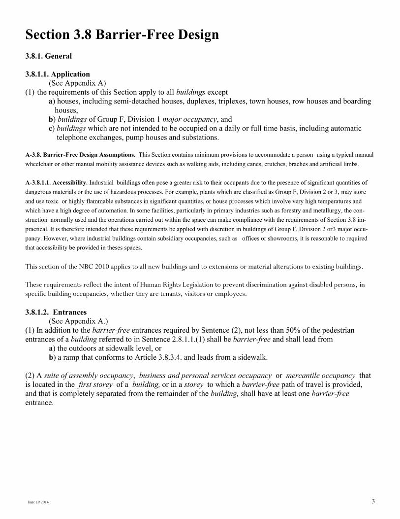
A-3.8.1.2. Entrances. An accessible route should exist from the sidewalk or roadway and parking area to an accessible building entrance. This route should be located so that persons with physical disabilities do not have to pass behind parked cars. To provide more general access to buildings, not less than 50% of the pedestrian entrances are required to be barrier-free. This should include a principal entrance. If the 50% calculation results in a fraction, the number of barrier-free entrances should be the next higher unit value. For the purpose of determining the number of entrances to a building, several adjacent doors in a bank of doors are considered to be a single entrance.
The main public entrance to the building should be accessible to all persons, regardless of disability. Secondary entrance or entrances that require keys or other devices for the use of disabled persons would be considered discriminatory. Where a secondary entrance is heavily utilized, for example; from adjacent to or from underground parking, these should also be designed to be accessible. Not les that 50% of the pedestrian entrances of a building referred to in Sentence 3.8.1.1..(1) shall be barrier-free.
Figure—3.8.1.2. & 3.8.2.2. Entrances
Not Acceptable
H/capped Parking
Secondary Entrance
Pedestrian Entrances
H/capped Parking
Accessible walks 3.8.3.2
Ramp 1100 mm min (3’ 7”)
Acceptable
Non accessible walk

June 19 2014 5
3.8.1.3. Barrier-Free Path of Travel
1) Except as required elsewhere in this Part or as permitted by Article 3.8.3.3. pertaining to doorways, the
unobstructed width of a barrier-free path of travel shall be not less than 920 mm (36 1/4”).
2) Interior and exterior walking surfaces that are within a barrier-free path of travel shall
a) have no opening that will permit the passage of a sphere more than 13 mm (1/2”) diam,
b) have any elongated openings oriented approximately perpendicular to the direction of travel,
c) be stable, firm and slip-resistant,
d) be bevelled at a maximum slope of 1 in 2 at changes in level not more than 13 mm (1/2”), and
e) be provided with sloped floors or ramps at changes in level more than 13 mm (1/2”).
3) A barrier-free path of travel is permitted to include ramps, passenger elevators or other platform-equipped
passenger-elevating devices to overcome a difference in level.
4) The width of a barrier-free path of travel that is more than 30 m (98’ 5 1/8”) long shall be increased to not
less than 1 500 mm (59 1/16”) for a length of 1 500 mm (59 1/16”) at intervals not exceeding 30 m
(98’ 5 1/8”). Figure- 3.8.1.3. Barrier-Free Path of Travel
3.8.1.4. Access to Storeys Served by Escalators and Moving Walks 1) In a building in which an escalator or inclined moving walk provides access to any floor level above or be-
low the entrance floor level, an interior barrier-free path of travel shall also be provided to that floor level.
(See Appendix A.)
2) The route from the escalator or inclined moving walk to the barrier-free path of travel that leads from floor
to floor as required by Sentence (1) shall be clearly indicated by appropriate signs.
A-3.8.1.4.(1) Access to Storeys Served by Escalators and Moving Walks. In some buildings, escalators and inclined moving walks are installed to provide transportation from one floor level to another floor level so as to increase the capacity to move large numbers of per-sons. Some buildings located on a sloping site are accessible from street level on more than one storey and an escalator or inclined mov-ing walk is provided or internal movement from floor to floor. In both these situations, a person with a physical disability must be provided with an equally convenient means of moving between the same floor levels within the building. This can be accomplished by
920mm
(36 1/4”)
Floor having no openings
greater than a13mm (1/2”)
June 19 2014 6
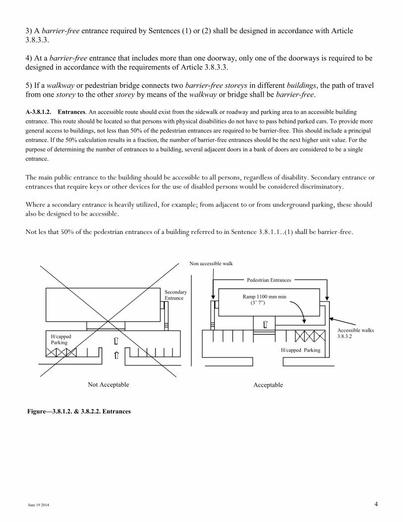
3.8.1.5. Controls
1)Except as required by Sentence 3.5.2.1.(3) regarding elevators, controls for the operation of building
services or safety devices, including electrical switches, thermostats and intercom switches, that are intended
to be operated by the occupant and are located in or adjacent to a barrier-free path of travel shall be accessible
to a person in a wheelchair, operable with one hand, and mounted between 400 mm (15 3/4”) and 1 200 mm
(47 1/4”) above the floor.
Figure—3.8.1.5. Controls
Mounting Heights for Controls Although some persons in wheelchairs can make a lateral approach and reach higher, a person making a
frontal approach to controls needs a mounting height to the center of the control not exceeding 1 200 mm
(47 1/4”).
3.8.2. Occupancy Requirements Some confusion exits concerning success to buildings. This section requires access to the entrance storey level
only. Access to other parts of the building would only be required where elevators, escalators, inclined moving
walks, or other platform-equipped passenger-elevating devices are provided. In designing or renovating a
building, attention to the location to the main functions of the building is needed. If the main use of the
building in on another level, then access to these areas should be considered (such access to comply with
3.8.3.5.(1).
40
0—
12
00
mm
(15
3/4
” —
47
1/4
”)
The operating button or switch cannot be located higher than 1 200mm (47 1/4”) above
the floor or lower than 400 mm (15 3/4”) above the floor

June 19 2014 7
3.8.2.1. Areas Requiring a Barrier-Free Path of Travel
(See Appendix A.)
1) Except as permitted by Sentence (2), a barrier-free path of travel from the entrances required by Sentences
3.8.1.2.(1) and (2) to be barrier-free shall be provided throughout the entrance storey and within all other
normally occupied floor areas served by a passenger elevator, escalator, inclined moving walk, or other
platform-equipped passenger-elevating device. (See Article 3.3.1.7. for additional requirements regarding
floor areas above or below the first storey to which a barrier-free path of travel is required.)
2) A barrier-free path of travel for persons in wheelchairs is not required
a) to service rooms,
b) to elevator machine rooms,
c) to janitor's rooms,
d) to service spaces,
e) to crawl spaces,
f) to attic or roof spaces,
g) to floor levels not served by a passenger elevator, a platform-equipped passenger-elevating device,
an escalator, or an inclined moving walk,
h) to high-hazard industrial occupancies,
i) within portions of a floor area with fixed seats in an assembly occupancy where those portions are
not part of the barrier-free path of travel to spaces designated for wheelchair use,
j) within floor levels of a suite of residential occupancy that are not at the same level as the entry level
to the suite,
k) within a suite of residential occupancy that has not been designated by an authority having
jurisdiction to be accessible for use by persons with physical disabilities, or
l) within those parts of a floor area that are not at the same level as the entry level, provided amenities
and uses provided on any raised or sunken level are accessible on the entry level by means of a
barrier-free path of travel.
Figure—3.8.2.1. Areas Requiring a Barrier-Free Path of Travel
At least one conveniently located checkout lane, service counter or gate, should be wide enough to allow the free passage and movement of a wheelchair at all times
810 mm (31 7/8”)
recommended
Counter
Checkout
lane
810mm (31 7/8”)
Recommended
Turnstiles
600mm (23 5/8”)
Recommended
810mm (31 7/8”)
Recommended 9
00
mm
(3
5 7
/16
”)
A gate of this type is accessible
but restrains shopping carts
June 19 2014 8
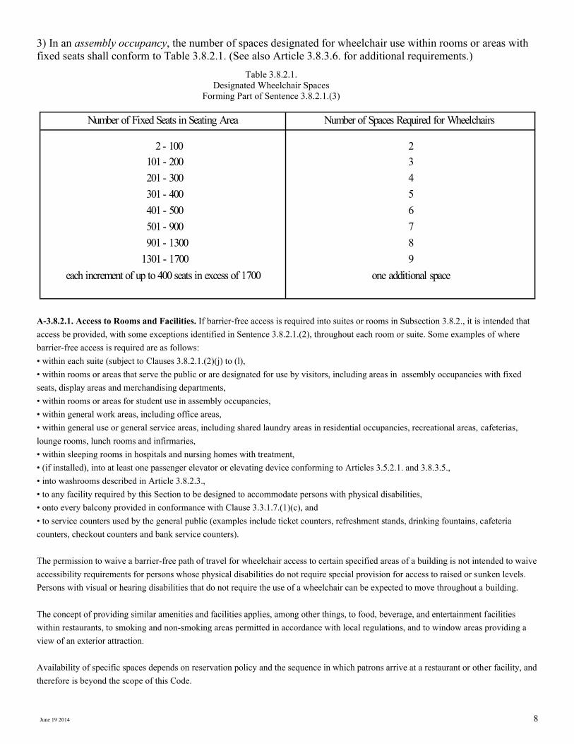
3) In an assembly occupancy, the number of spaces designated for wheelchair use within rooms or areas with
fixed seats shall conform to Table 3.8.2.1. (See also Article 3.8.3.6. for additional requirements.)
A-3.8.2.1. Access to Rooms and Facilities. If barrier-free access is required into suites or rooms in Subsection 3.8.2., it is intended that access be provided, with some exceptions identified in Sentence 3.8.2.1.(2), throughout each room or suite. Some examples of where barrier-free access is required are as follows: • within each suite (subject to Clauses 3.8.2.1.(2)(j) to (l), • within rooms or areas that serve the public or are designated for use by visitors, including areas in assembly occupancies with fixed seats, display areas and merchandising departments, • within rooms or areas for student use in assembly occupancies, • within general work areas, including office areas, • within general use or general service areas, including shared laundry areas in residential occupancies, recreational areas, cafeterias, lounge rooms, lunch rooms and infirmaries, • within sleeping rooms in hospitals and nursing homes with treatment, • (if installed), into at least one passenger elevator or elevating device conforming to Articles 3.5.2.1. and 3.8.3.5., • into washrooms described in Article 3.8.2.3., • to any facility required by this Section to be designed to accommodate persons with physical disabilities, • onto every balcony provided in conformance with Clause 3.3.1.7.(1)(c), and • to service counters used by the general public (examples include ticket counters, refreshment stands, drinking fountains, cafeteria counters, checkout counters and bank service counters). The permission to waive a barrier-free path of travel for wheelchair access to certain specified areas of a building is not intended to waive accessibility requirements for persons whose physical disabilities do not require special provision for access to raised or sunken levels. Persons with visual or hearing disabilities that do not require the use of a wheelchair can be expected to move throughout a building. The concept of providing similar amenities and facilities applies, among other things, to food, beverage, and entertainment facilities within restaurants, to smoking and non-smoking areas permitted in accordance with local regulations, and to window areas providing a view of an exterior attraction. Availability of specific spaces depends on reservation policy and the sequence in which patrons arrive at a restaurant or other facility, and therefore is beyond the scope of this Code.
Number of Fixed Seats in Seating Area Number of Spaces Required for Wheelchairs
2 - 100
101 - 200
201 - 300
301 - 400
401 - 500
501 - 900
901 - 1300
1301 - 1700
each increment of up to 400 seats in excess of 1700
2
3
4
5
6
7
8
9
one additional space
Table 3.8.2.1.
Designated Wheelchair Spaces
Forming Part of Sentence 3.8.2.1.(3)
June 19 2014 9
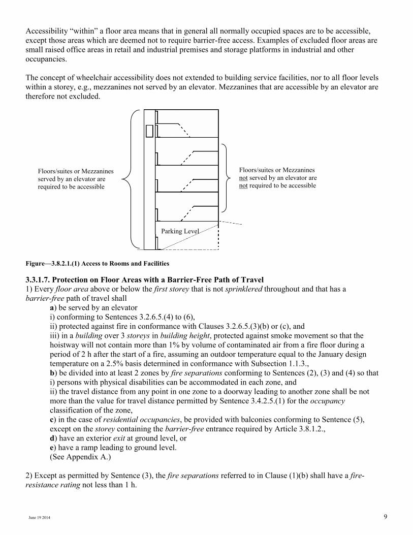
Accessibility “within” a floor area means that in general all normally occupied spaces are to be accessible,
except those areas which are deemed not to require barrier-free access. Examples of excluded floor areas are
small raised office areas in retail and industrial premises and storage platforms in industrial and other
occupancies.
The concept of wheelchair accessibility does not extended to building service facilities, nor to all floor levels
within a storey, e.g., mezzanines not served by an elevator. Mezzanines that are accessible by an elevator are
therefore not excluded.
Figure—3.8.2.1.(1) Access to Rooms and Facilities
3.3.1.7. Protection on Floor Areas with a Barrier-Free Path of Travel
1) Every floor area above or below the first storey that is not sprinklered throughout and that has a
barrier-free path of travel shall
a) be served by an elevator
i) conforming to Sentences 3.2.6.5.(4) to (6),
ii) protected against fire in conformance with Clauses 3.2.6.5.(3)(b) or (c), and
iii) in a building over 3 storeys in building height, protected against smoke movement so that the
hoistway will not contain more than 1% by volume of contaminated air from a fire floor during a
period of 2 h after the start of a fire, assuming an outdoor temperature equal to the January design
temperature on a 2.5% basis determined in conformance with Subsection 1.1.3.,
b) be divided into at least 2 zones by fire separations conforming to Sentences (2), (3) and (4) so that
i) persons with physical disabilities can be accommodated in each zone, and
ii) the travel distance from any point in one zone to a doorway leading to another zone shall be not
more than the value for travel distance permitted by Sentence 3.4.2.5.(1) for the occupancy
classification of the zone,
c) in the case of residential occupancies, be provided with balconies conforming to Sentence (5),
except on the storey containing the barrier-free entrance required by Article 3.8.1.2.,
d) have an exterior exit at ground level, or
e) have a ramp leading to ground level.
(See Appendix A.)
2) Except as permitted by Sentence (3), the fire separations referred to in Clause (1)(b) shall have a fire-
resistance rating not less than 1 h.
Parking Level
Floors/suites or Mezzanines
served by an elevator are
required to be accessible
Floors/suites or Mezzanines
not served by an elevator are
not required to be accessible
June 19 2014
3) The fire-resistance rating of the fire separations referred to in Clause (1)(b) is permitted to be less than 1 h
but not less than 45 min provided the fire-resistance rating required by Subsection 3.2.2. is permitted to be less
than 1 h for
a) the floor assembly above the floor area, or
b) the floor assembly below the floor area, if there is no floor assembly above.
4) A door acting as a closure in a fire separation referred to in Clause (1)(b) shall be weatherstripped or
otherwise designed and installed to retard the passage of smoke.
(See A-3.3.3.5.(6) in Appendix A.)
5) A balcony required by Clause (1)(c) shall
a) have direct barrier-free access from the suite or floor area
b) be not less than 1 500m (59 1/16”) deep from the outside face of the exterior wall to the inside edge
of the balcony, and
c) provide not less than 1.5 m2 (16.1ft2) of balcony space for each nonambulatory occupant and 0.5 m2
(5.4ft2) for each ambulatory occupant.
A-3.3.1.7.(1) Temporary Refuge for Persons with Disabilities. These measures are intended to provide temporary refuge for persons with disabilities. It is acknowledged, however, that the measures cannot provide absolute safety for all occupants in the fire area. It may, therefore, be necessary to develop special arrangements in the fire safety plan to evacuate persons with disabilities from these areas. Details for a suitable plan are contained in the NFC. The protected elevator referred to in Clause 3.3.1.7.(1)(a) is intended to be used by firefighters as a means for evacuating persons with disabilities. It is not intended that this elevator be used by persons with disabilities as a means of egress without the assistance of firefighters. If an estimate is to be made of the number of persons with disabilities in a floor area who can be accommodated in each zone in Clause 3.3.1.7.(1)(b), this estimate may be based on Table 3.8.2.1., which is used to determine the minimum number of spaces to be provided for
wheelchair occupants in fixed seating areas. If more precise information is available, it should be used for sizing the zones.
3.2.6.5. Elevator for Use by Firefighters
1) At least one elevator shall be provided for use by firefighters in conformance with Sentences (2) to (6).
2) The elevator referred to in Sentence (1) shall have a useable platform area not less than 2.2 m2 (23.68sqft)
and shall be capable of carrying a load of 900 kg (1984 lbs) to the top floor that it serves from a landing on the
storey containing the entrance for firefighter access referred to in Articles 3.2.5.4. and 3.2.5.5. within 1 min.
3) Each elevator for use by firefighters shall
a) be provided with a closure at each shaft opening so that the interlock mechanism remains
mechanically engaged and electrical continuity is maintained in the interlock circuits and associated
wiring for a period of not less than 1 h when the assembly is subjected to the standard fire exposure
described in CAN4-S104-M, “Fire Tests of Door Assemblies,”
b) be protected with a vestibule containing no occupancy and separated from the remainder of the floor
area by a fire separation having a fire-resistance rating not less than 45 min, or
c) be protected with a corridor containing no occupancy and separated from the remainder of the
building by a fire separation having a fire-resistance rating not less than 1 h.
June 19 2014
3.8.2.2. Access to Parking Areas
(See Appendix A.)
1) If exterior parking is provided, a barrier-free path of travel shall be provided between the exterior parking
area and a barrier-free entrance conforming to Article 3.8.1.2. (See Appendix A.)
2) If a passenger elevator serves one or more indoor parking levels, a barrier-free path of travel shall be
provided between at least one parking level and all other parts of the building required to be provided with
barrier-free access in accordance with Article 3.8.2.1.
3) If an exterior passenger loading zone is provided, it shall have
a) an access aisle not less than 1 500 mm (59 1/16”) wide and 6 000 mm (19’ 8 1/4”’) long adjacent
and parallel to the vehicle pull-up space,
b) a curb ramp, where there are curbs between the access aisle and the vehicle pull-up space, and
c) a clear height of not less than 2 750 mm (9’ 0 1/4”) at the pull-up space and along the vehicle access
and egress routes.
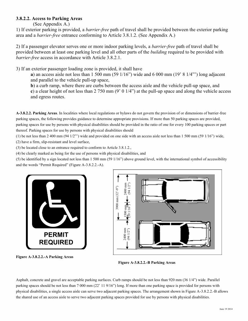
A-3.8.2.2. Parking Areas. In localities where local regulations or bylaws do not govern the provision of or dimensions of barrier-free parking spaces, the following provides guidance to determine appropriate provisions. If more than 50 parking spaces are provided, parking spaces for use by persons with physical disabilities should be provided in the ratio of one for every 100 parking spaces or part thereof. Parking spaces for use by persons with physical disabilities should (1) be not less than 2 400 mm (94 1/2”’) wide and provided on one side with an access aisle not less than 1 500 mm (59 1/16”) wide, (2) have a firm, slip-resistant and level surface, (3) be located close to an entrance required to conform to Article 3.8.1.2., (4) be clearly marked as being for the use of persons with physical disabilities, and (5) be identified by a sign located not less than 1 500 mm (59 1/16”) above ground level, with the international symbol of accessibility and the words “Permit Required” (Figure A-3.8.2.2.-A). Figure A-3.8.2.2.-A Parking Areas Figure A-3.8.2.2.-B Parking Areas Asphalt, concrete and gravel are acceptable parking surfaces. Curb ramps should be not less than 920 mm (36 1/4”) wide. Parallel parking spaces should be not less than 7 000 mm (22’ 11 9/16”) long. If more than one parking space is provided for persons with physical disabilities, a single access aisle can serve two adjacent parking spaces. The arrangement shown in Figure A-3.8.2.2.-B allows the shared use of an access aisle to serve two adjacent parking spaces provided for use by persons with physical disabilities.
PERMIT REQUIRED
3900
mm
(12
’-9
”)
2400
mm
(9
4 1
/2”)
1500
mm
(59
1/1
6”)
2400
mm
(9
4 1
/2”)
June 19 2014
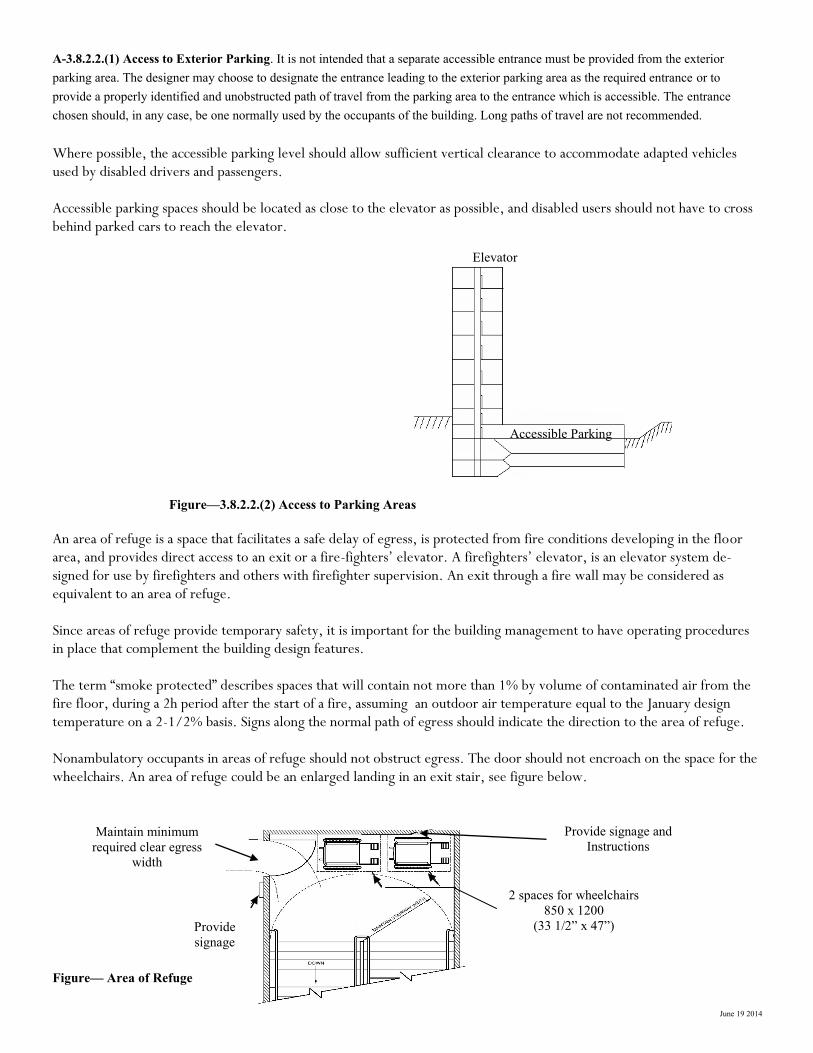
A-3.8.2.2.(1) Access to Exterior Parking. It is not intended that a separate accessible entrance must be provided from the exterior parking area. The designer may choose to designate the entrance leading to the exterior parking area as the required entrance or to provide a properly identified and unobstructed path of travel from the parking area to the entrance which is accessible. The entrance chosen should, in any case, be one normally used by the occupants of the building. Long paths of travel are not recommended.
Where possible, the accessible parking level should allow sufficient vertical clearance to accommodate adapted vehicles used by disabled drivers and passengers. Accessible parking spaces should be located as close to the elevator as possible, and disabled users should not have to cross behind parked cars to reach the elevator.
Figure—3.8.2.2.(2) Access to Parking Areas
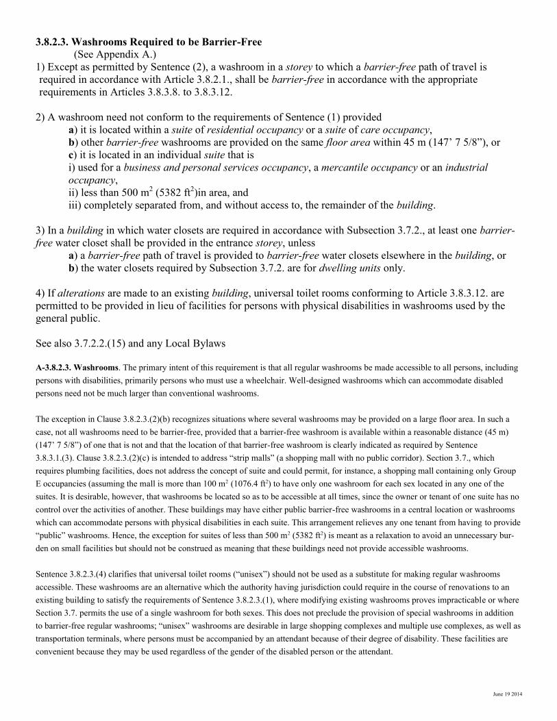
An area of refuge is a space that facilitates a safe delay of egress, is protected from fire conditions developing in the floor area, and provides direct access to an exit or a fire-fighters’ elevator. A firefighters’ elevator, is an elevator system de-signed for use by firefighters and others with firefighter supervision. An exit through a fire wall may be considered as equivalent to an area of refuge. Since areas of refuge provide temporary safety, it is important for the building management to have operating procedures in place that complement the building design features. The term “smoke protected” describes spaces that will contain not more than 1% by volume of contaminated air from the fire floor, during a 2h period after the start of a fire, assuming an outdoor air temperature equal to the January design temperature on a 2-1/2% basis. Signs along the normal path of egress should indicate the direction to the area of refuge. Nonambulatory occupants in areas of refuge should not obstruct egress. The door should not encroach on the space for the wheelchairs. An area of refuge could be an enlarged landing in an exit stair, see figure below.
Figure— Area of Refuge
Elevator
Accessible Parking
2 spaces for wheelchairs
850 x 1200
(33 1/2” x 47”)
Maintain minimum
required clear egress
width
Provide signage and
Instructions
Provide
signage
June 19 2014
3.8.2.3. Washrooms Required to be Barrier-Free
(See Appendix A.)
1) Except as permitted by Sentence (2), a washroom in a storey to which a barrier-free path of travel is
required in accordance with Article 3.8.2.1., shall be barrier-free in accordance with the appropriate
requirements in Articles 3.8.3.8. to 3.8.3.12.
2) A washroom need not conform to the requirements of Sentence (1) provided
a) it is located within a suite of residential occupancy or a suite of care occupancy,
b) other barrier-free washrooms are provided on the same floor area within 45 m (147’ 7 5/8”), or
c) it is located in an individual suite that is
i) used for a business and personal services occupancy, a mercantile occupancy or an industrial
occupancy,
ii) less than 500 m2 (5382 ft2)in area, and
iii) completely separated from, and without access to, the remainder of the building.
3) In a building in which water closets are required in accordance with Subsection 3.7.2., at least one barrier-
free water closet shall be provided in the entrance storey, unless
a) a barrier-free path of travel is provided to barrier-free water closets elsewhere in the building, or
b) the water closets required by Subsection 3.7.2. are for dwelling units only.
4) If alterations are made to an existing building, universal toilet rooms conforming to Article 3.8.3.12. are
permitted to be provided in lieu of facilities for persons with physical disabilities in washrooms used by the
general public.
See also 3.7.2.2.(15) and any Local Bylaws
A-3.8.2.3. Washrooms. The primary intent of this requirement is that all regular washrooms be made accessible to all persons, including persons with disabilities, primarily persons who must use a wheelchair. Well-designed washrooms which can accommodate disabled persons need not be much larger than conventional washrooms. The exception in Clause 3.8.2.3.(2)(b) recognizes situations where several washrooms may be provided on a large floor area. In such a case, not all washrooms need to be barrier-free, provided that a barrier-free washroom is available within a reasonable distance (45 m) (147’ 7 5/8”) of one that is not and that the location of that barrier-free washroom is clearly indicated as required by Sentence 3.8.3.1.(3). Clause 3.8.2.3.(2)(c) is intended to address “strip malls” (a shopping mall with no public corridor). Section 3.7., which requires plumbing facilities, does not address the concept of suite and could permit, for instance, a shopping mall containing only Group E occupancies (assuming the mall is more than 100 m2 (1076.4 ft2) to have only one washroom for each sex located in any one of the suites. It is desirable, however, that washrooms be located so as to be accessible at all times, since the owner or tenant of one suite has no control over the activities of another. These buildings may have either public barrier-free washrooms in a central location or washrooms which can accommodate persons with physical disabilities in each suite. This arrangement relieves any one tenant from having to provide “public” washrooms. Hence, the exception for suites of less than 500 m2 (5382 ft2) is meant as a relaxation to avoid an unnecessary bur-den on small facilities but should not be construed as meaning that these buildings need not provide accessible washrooms. Sentence 3.8.2.3.(4) clarifies that universal toilet rooms (“unisex”) should not be used as a substitute for making regular washrooms accessible. These washrooms are an alternative which the authority having jurisdiction could require in the course of renovations to an existing building to satisfy the requirements of Sentence 3.8.2.3.(1), where modifying existing washrooms proves impracticable or where Section 3.7. permits the use of a single washroom for both sexes. This does not preclude the provision of special washrooms in addition to barrier-free regular washrooms; “unisex” washrooms are desirable in large shopping complexes and multiple use complexes, as well as transportation terminals, where persons must be accompanied by an attendant because of their degree of disability. These facilities are convenient because they may be used regardless of the gender of the disabled person or the attendant.
June 19 2014
3.8.3. Design Standards
3.8.3.1. Accessibility Signs
1) Signs incorporating the international symbol of accessibility for persons with physical disabilities shall be
installed to indicate the location of a barrier-free entrance.
(See Appendix A.)
2) A washroom, shower, elevator or parking space designed to be barrier-free shall be identified by a sign
consisting of the international symbol of accessibility for persons with physical disabilities and by appropriate
graphic or written directions to indicate clearly the type of facility available.
(See Appendix A.)
3) If a washroom is not designed to accommodate persons with physical disabilities in a storey to which a
barrier-free path of travel is required, signs shall be provided to indicate the location of barrier-free facilities.
(See Appendix A.)
4) Signs incorporating the symbol of accessibility for persons with hearing disabilities shall be installed to
indicate the location of facilities for persons with hearing disabilities.
(See Appendix A.)
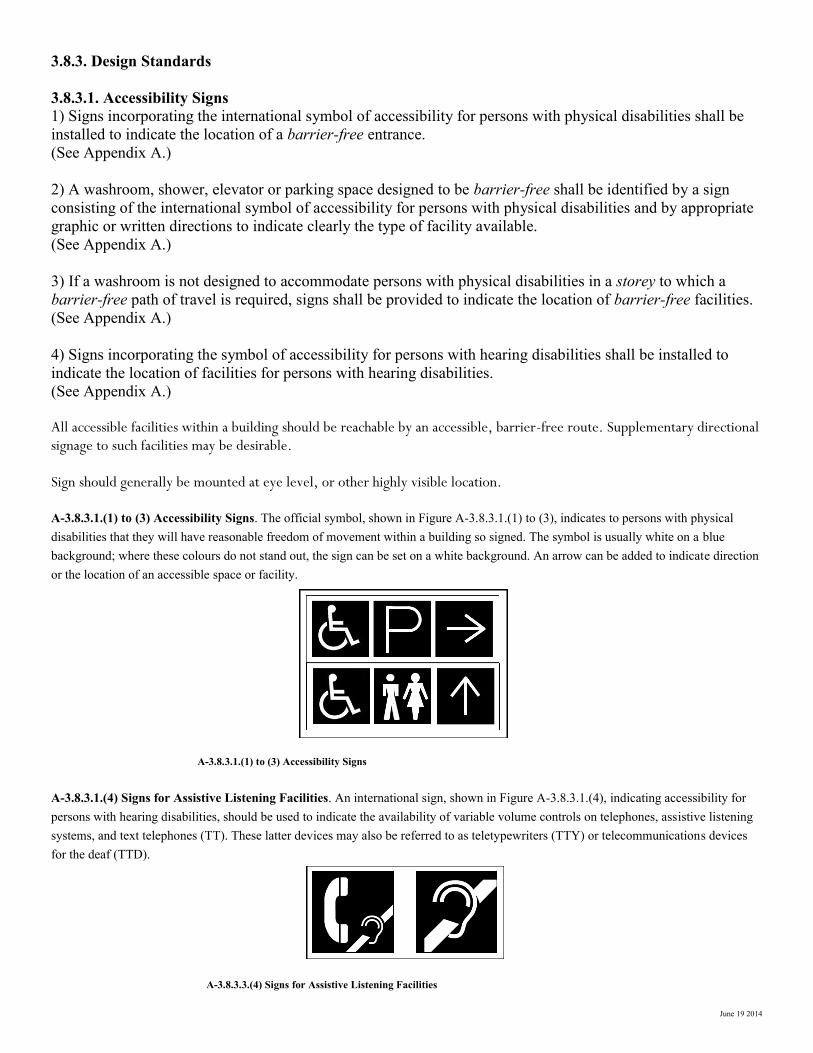
All accessible facilities within a building should be reachable by an accessible, barrier-free route. Supplementary directional signage to such facilities may be desirable. Sign should generally be mounted at eye level, or other highly visible location. A-3.8.3.1.(1) to (3) Accessibility Signs. The official symbol, shown in Figure A-3.8.3.1.(1) to (3), indicates to persons with physical disabilities that they will have reasonable freedom of movement within a building so signed. The symbol is usually white on a blue background; where these colours do not stand out, the sign can be set on a white background. An arrow can be added to indicate direction or the location of an accessible space or facility. A-3.8.3.1.(1) to (3) Accessibility Signs A-3.8.3.1.(4) Signs for Assistive Listening Facilities. An international sign, shown in Figure A-3.8.3.1.(4), indicating accessibility for persons with hearing disabilities, should be used to indicate the availability of variable volume controls on telephones, assistive listening systems, and text telephones (TT). These latter devices may also be referred to as teletypewriters (TTY) or telecommunications devices for the deaf (TTD). A-3.8.3.3.(4) Signs for Assistive Listening Facilities
June 19 2014
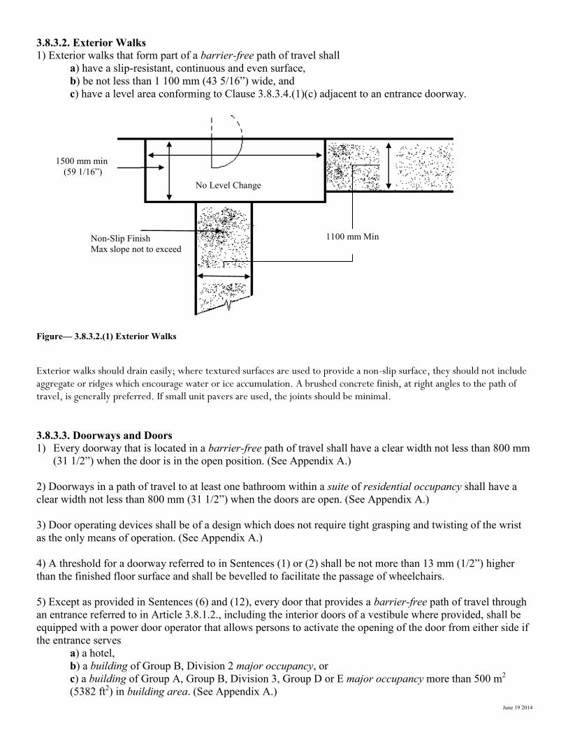
3.8.3.2. Exterior Walks
1) Exterior walks that form part of a barrier-free path of travel shall
a) have a slip-resistant, continuous and even surface,
b) be not less than 1 100 mm (43 5/16”) wide, and
c) have a level area conforming to Clause 3.8.3.4.(1)(c) adjacent to an entrance doorway.
Figure— 3.8.3.2.(1) Exterior Walks
Exterior walks should drain easily; where textured surfaces are used to provide a non-slip surface, they should not include aggregate or ridges which encourage water or ice accumulation. A brushed concrete finish, at right angles to the path of travel, is generally preferred. If small unit pavers are used, the joints should be minimal.
3.8.3.3. Doorways and Doors
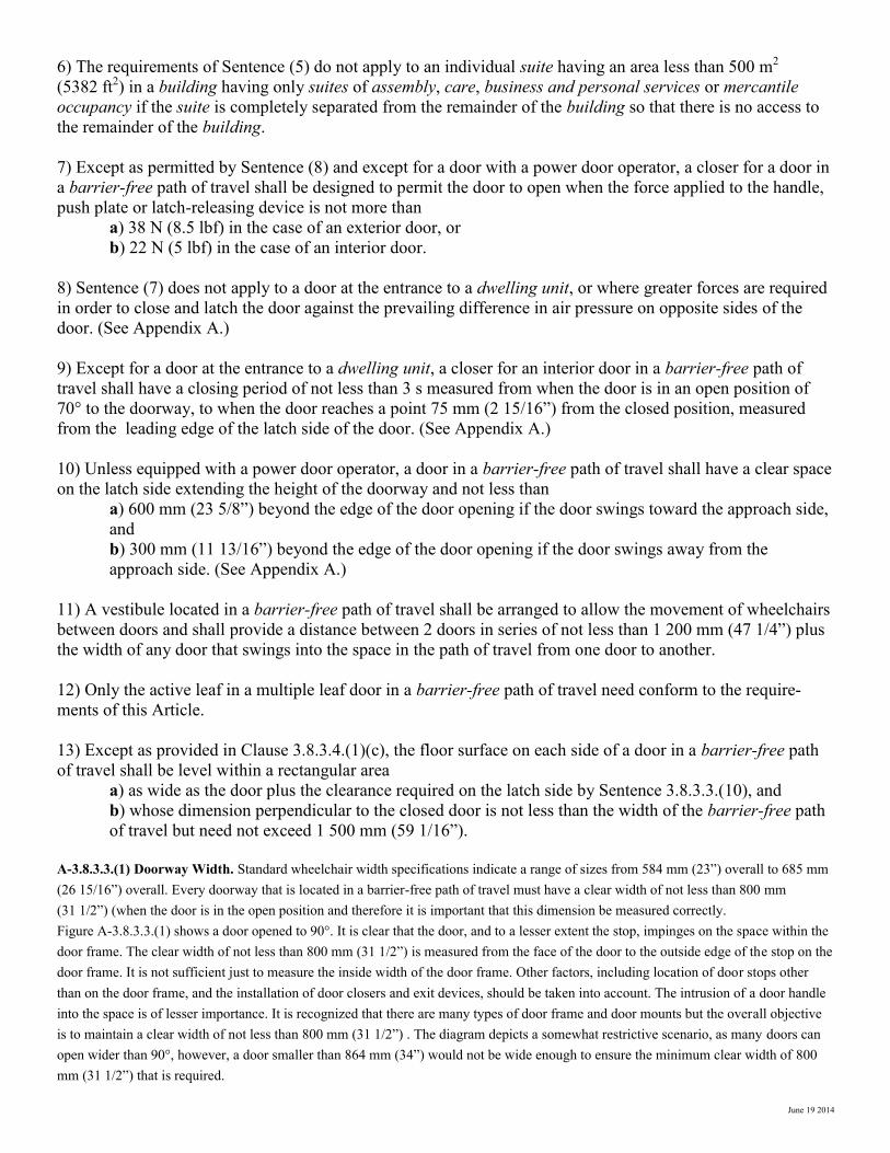
1) Every doorway that is located in a barrier-free path of travel shall have a clear width not less than 800 mm
(31 1/2”) when the door is in the open position. (See Appendix A.)
2) Doorways in a path of travel to at least one bathroom within a suite of residential occupancy shall have a
clear width not less than 800 mm (31 1/2”) when the doors are open. (See Appendix A.)
3) Door operating devices shall be of a design which does not require tight grasping and twisting of the wrist
as the only means of operation. (See Appendix A.)
4) A threshold for a doorway referred to in Sentences (1) or (2) shall be not more than 13 mm (1/2”) higher
than the finished floor surface and shall be bevelled to facilitate the passage of wheelchairs.
5) Except as provided in Sentences (6) and (12), every door that provides a barrier-free path of travel through
an entrance referred to in Article 3.8.1.2., including the interior doors of a vestibule where provided, shall be
equipped with a power door operator that allows persons to activate the opening of the door from either side if
the entrance serves
a) a hotel,
b) a building of Group B, Division 2 major occupancy, or
c) a building of Group A, Group B, Division 3, Group D or E major occupancy more than 500 m2
(5382 ft2) in building area. (See Appendix A.)
1500 mm min
(59 1/16”)
1100 mm Min
No Level Change
Non-Slip Finish
Max slope not to exceed
June 19 2014
6) The requirements of Sentence (5) do not apply to an individual suite having an area less than 500 m2
(5382 ft2) in a building having only suites of assembly, care, business and personal services or mercantile
occupancy if the suite is completely separated from the remainder of the building so that there is no access to
the remainder of the building.
7) Except as permitted by Sentence (8) and except for a door with a power door operator, a closer for a door in
a barrier-free path of travel shall be designed to permit the door to open when the force applied to the handle,
push plate or latch-releasing device is not more than
a) 38 N (8.5 lbf) in the case of an exterior door, or
b) 22 N (5 lbf) in the case of an interior door.
8) Sentence (7) does not apply to a door at the entrance to a dwelling unit, or where greater forces are required
in order to close and latch the door against the prevailing difference in air pressure on opposite sides of the
door. (See Appendix A.)
9) Except for a door at the entrance to a dwelling unit, a closer for an interior door in a barrier-free path of
travel shall have a closing period of not less than 3 s measured from when the door is in an open position of
70° to the doorway, to when the door reaches a point 75 mm (2 15/16”) from the closed position, measured
from the leading edge of the latch side of the door. (See Appendix A.)
10) Unless equipped with a power door operator, a door in a barrier-free path of travel shall have a clear space
on the latch side extending the height of the doorway and not less than
a) 600 mm (23 5/8”) beyond the edge of the door opening if the door swings toward the approach side,
and
b) 300 mm (11 13/16”) beyond the edge of the door opening if the door swings away from the
approach side. (See Appendix A.)
11) A vestibule located in a barrier-free path of travel shall be arranged to allow the movement of wheelchairs
between doors and shall provide a distance between 2 doors in series of not less than 1 200 mm (47 1/4”) plus
the width of any door that swings into the space in the path of travel from one door to another.
12) Only the active leaf in a multiple leaf door in a barrier-free path of travel need conform to the require-
ments of this Article.
13) Except as provided in Clause 3.8.3.4.(1)(c), the floor surface on each side of a door in a barrier-free path
of travel shall be level within a rectangular area
a) as wide as the door plus the clearance required on the latch side by Sentence 3.8.3.3.(10), and
b) whose dimension perpendicular to the closed door is not less than the width of the barrier-free path
of travel but need not exceed 1 500 mm (59 1/16”).
A-3.8.3.3.(1) Doorway Width. Standard wheelchair width specifications indicate a range of sizes from 584 mm (23”) overall to 685 mm (26 15/16”) overall. Every doorway that is located in a barrier-free path of travel must have a clear width of not less than 800 mm (31 1/2”) (when the door is in the open position and therefore it is important that this dimension be measured correctly. Figure A-3.8.3.3.(1) shows a door opened to 90°. It is clear that the door, and to a lesser extent the stop, impinges on the space within the door frame. The clear width of not less than 800 mm (31 1/2”) is measured from the face of the door to the outside edge of the stop on the door frame. It is not sufficient just to measure the inside width of the door frame. Other factors, including location of door stops other than on the door frame, and the installation of door closers and exit devices, should be taken into account. The intrusion of a door handle into the space is of lesser importance. It is recognized that there are many types of door frame and door mounts but the overall objective is to maintain a clear width of not less than 800 mm (31 1/2”) . The diagram depicts a somewhat restrictive scenario, as many doors can open wider than 90°, however, a door smaller than 864 mm (34”) would not be wide enough to ensure the minimum clear width of 800 mm (31 1/2”) that is required.
June 19 2014
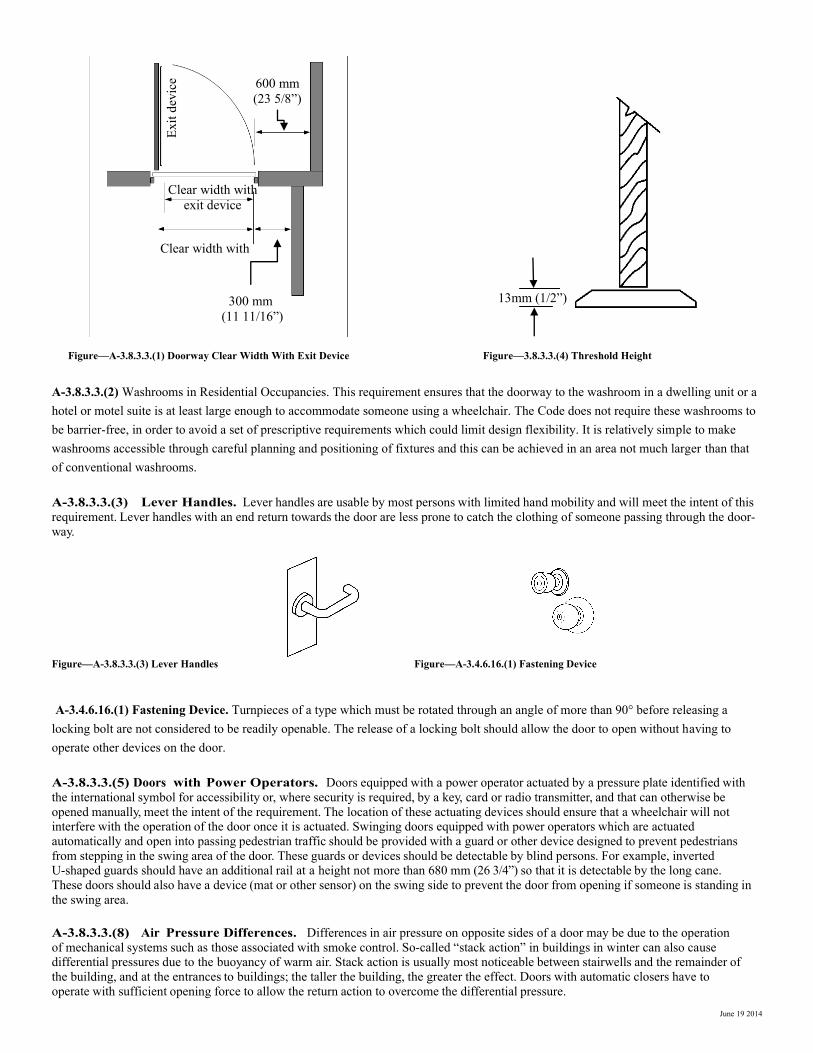
Figure—A-3.8.3.3.(1) Doorway Clear Width With Exit Device Figure—3.8.3.3.(4) Threshold Height A-3.8.3.3.(2) Washrooms in Residential Occupancies. This requirement ensures that the doorway to the washroom in a dwelling unit or a hotel or motel suite is at least large enough to accommodate someone using a wheelchair. The Code does not require these washrooms to be barrier-free, in order to avoid a set of prescriptive requirements which could limit design flexibility. It is relatively simple to make washrooms accessible through careful planning and positioning of fixtures and this can be achieved in an area not much larger than that of conventional washrooms. A-3.8.3.3.(3) Lever Handles. Lever handles are usable by most persons with limited hand mobility and will meet the intent of this requirement. Lever handles with an end return towards the door are less prone to catch the clothing of someone passing through the door-way. Figure—A-3.8.3.3.(3) Lever Handles Figure—A-3.4.6.16.(1) Fastening Device
A-3.4.6.16.(1) Fastening Device. Turnpieces of a type which must be rotated through an angle of more than 90° before releasing a locking bolt are not considered to be readily openable. The release of a locking bolt should allow the door to open without having to operate other devices on the door. A-3.8.3.3.(5) Doors with Power Operators. Doors equipped with a power operator actuated by a pressure plate identified with the international symbol for accessibility or, where security is required, by a key, card or radio transmitter, and that can otherwise be opened manually, meet the intent of the requirement. The location of these actuating devices should ensure that a wheelchair will not interfere with the operation of the door once it is actuated. Swinging doors equipped with power operators which are actuated automatically and open into passing pedestrian traffic should be provided with a guard or other device designed to prevent pedestrians from stepping in the swing area of the door. These guards or devices should be detectable by blind persons. For example, inverted U-shaped guards should have an additional rail at a height not more than 680 mm (26 3/4”) so that it is detectable by the long cane. These doors should also have a device (mat or other sensor) on the swing side to prevent the door from opening if someone is standing in the swing area. A-3.8.3.3.(8) Air Pressure Differences. Differences in air pressure on opposite sides of a door may be due to the operation of mechanical systems such as those associated with smoke control. So-called “stack action” in buildings in winter can also cause differential pressures due to the buoyancy of warm air. Stack action is usually most noticeable between stairwells and the remainder of the building, and at the entrances to buildings; the taller the building, the greater the effect. Doors with automatic closers have to operate with sufficient opening force to allow the return action to overcome the differential pressure.
13mm (1/2”)
Clear width with
exit device
600 mm
(23 5/8”)
300 mm
(11 11/16”)
Clear width with
Exit
dev
ice

June 19 2014
600mm (23 5/8”) min 300mm (23 13/16”)
GC00052A
A-3.8.3.3.(9) Delayed Action on Door Closers. In some circumstances, closers with a delay feature which keeps the door open for several seconds before it begins to close might be desirable. However, closers with this feature have limited back-check, a feature of a normal door closer where resistance to opening increases as the door reaches the full arc of swing. Doors equipped with a delayed action closer are therefore more susceptible to damage should the door be opened with too much force or should someone try to force it closed, thinking the closer has failed to operate. Delayed action closers are not recommended for such occupancies as schools. A-3.8.3.3.(10) Clearance at Doorways. Sufficient clearance must be provided on the latch side of doors for a user to operate the door-opening mechanism and open the door without interference from the wheelchair. This is particularly important for a door swinging towards the approach side. See Figure A-3.8.3.3.(10). Figure—3.8.3.3.(10) Clear Space At Sides of Doors Figure—3.8.3.3.(11) Vestibule In a Barrier-Free Path of Travel
120
0 m
m
1200 mm
1500 mm (59 1/16”) min
1200 mm min
1200 m
m (
47 1
/4”)
15
00
mm
Minimum clear areas
1500 min (59 1/16”)
1500 m
in
1200 min
Door
Width
1200 min (47 1/4”)
1200 m
in
300 min (11 13/16”)
June 19 2014
3.8.3.4. Ramps
1) A ramp located in a barrier-free path of travel shall
a) have a clear width not less than 870 mm (34 1/4”) (see A-3.4.3.4. in Appendix A),
b) have a slope not more than 1 in 12 (see Appendix A),
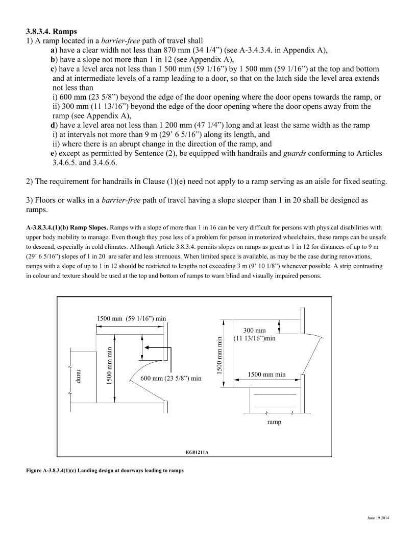
c) have a level area not less than 1 500 mm (59 1/16”) by 1 500 mm (59 1/16”) at the top and bottom
and at intermediate levels of a ramp leading to a door, so that on the latch side the level area extends
not less than
i) 600 mm (23 5/8”) beyond the edge of the door opening where the door opens towards the ramp, or
ii) 300 mm (11 13/16”) beyond the edge of the door opening where the door opens away from the
ramp (see Appendix A),
d) have a level area not less than 1 200 mm (47 1/4”) long and at least the same width as the ramp
i) at intervals not more than 9 m (29’ 6 5/16”) along its length, and
ii) where there is an abrupt change in the direction of the ramp, and
e) except as permitted by Sentence (2), be equipped with handrails and guards conforming to Articles
3.4.6.5. and 3.4.6.6.
2) The requirement for handrails in Clause (1)(e) need not apply to a ramp serving as an aisle for fixed seating.
3) Floors or walks in a barrier-free path of travel having a slope steeper than 1 in 20 shall be designed as
ramps.
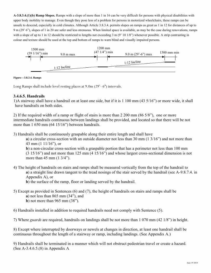
A-3.8.3.4.(1)(b) Ramp Slopes. Ramps with a slope of more than 1 in 16 can be very difficult for persons with physical disabilities with upper body mobility to manage. Even though they pose less of a problem for person in motorized wheelchairs, these ramps can be unsafe to descend, especially in cold climates. Although Article 3.8.3.4. permits slopes on ramps as great as 1 in 12 for distances of up to 9 m (29’ 6 5/16”) slopes of 1 in 20 are safer and less strenuous. When limited space is available, as may be the case during renovations, ramps with a slope of up to 1 in 12 should be restricted to lengths not exceeding 3 m (9’ 10 1/8”) whenever possible. A strip contrasting in colour and texture should be used at the top and bottom of ramps to warn blind and visually impaired persons.
Figure A-3.8.3.4(1)(c) Landing design at doorways leading to ramps
15
00
mm
min
1500 mm (59 1/16”) min
600 mm (23 5/8”) min
ram
p
15
00
mm
min
1500 mm min
ramp
300 mm
(11 13/16”)min
EG01211A
June 19 2014
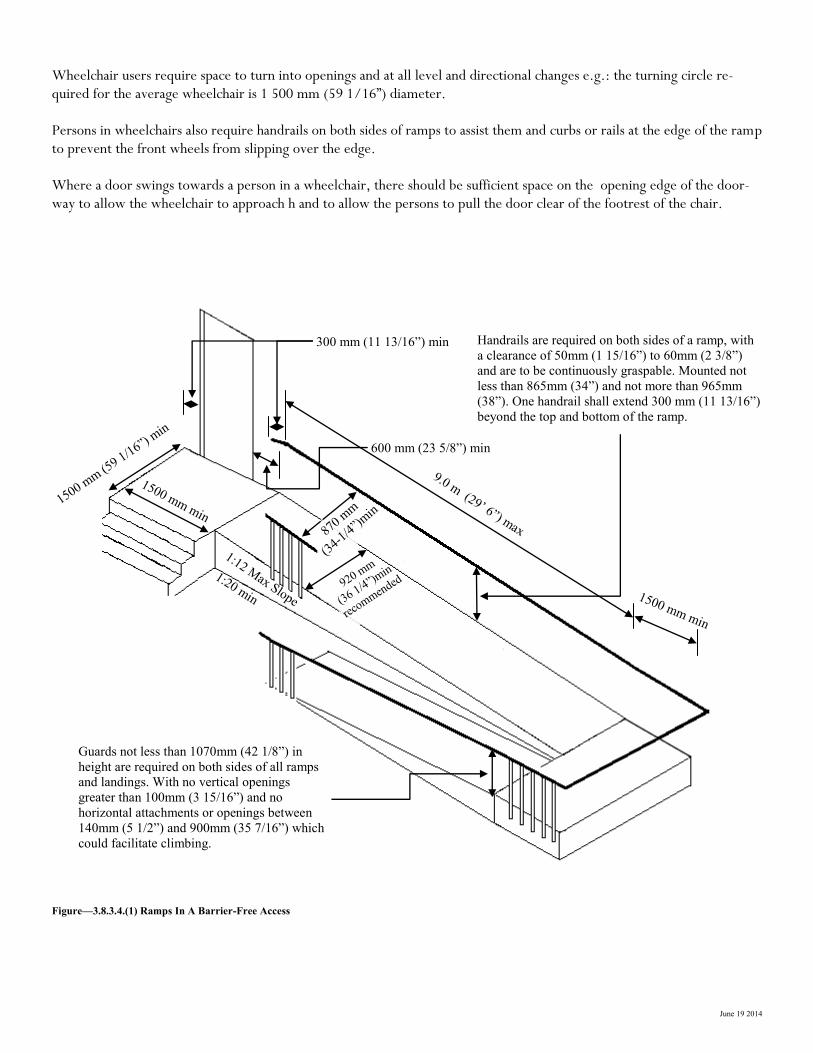
Wheelchair users require space to turn into openings and at all level and directional changes e.g.: the turning circle re-quired for the average wheelchair is 1 500 mm (59 1/16”) diameter. Persons in wheelchairs also require handrails on both sides of ramps to assist them and curbs or rails at the edge of the ramp to prevent the front wheels from slipping over the edge. Where a door swings towards a person in a wheelchair, there should be sufficient space on the opening edge of the door-way to allow the wheelchair to approach h and to allow the persons to pull the door clear of the footrest of the chair.
Figure—3.8.3.4.(1) Ramps In A Barrier-Free Access
9.0 m (29’ 6”) max
300 mm (11 13/16”) min
920 mm
(36 1/4”)m
in
recommen
ded
1500 mm min
1:12 Max Slope
1:20 min
1500 mm (5
9 1/16”) min
1500 mm min
600 mm (23 5/8”) min
870 mm
(34-
1/4”)
min
Handrails are required on both sides of a ramp, with
a clearance of 50mm (1 15/16”) to 60mm (2 3/8”)
and are to be continuously graspable. Mounted not
less than 865mm (34”) and not more than 965mm
(38”). One handrail shall extend 300 mm (11 13/16”)
beyond the top and bottom of the ramp.
Guards not less than 1070mm (42 1/8”) in
height are required on both sides of all ramps
and landings. With no vertical openings
greater than 100mm (3 15/16”) and no
horizontal attachments or openings between
140mm (5 1/2”) and 900mm (35 7/16”) which
could facilitate climbing.
June 19 2014
A-3.8.3.4.(1)(b) Ramp Slopes. Ramps with a slope of more than 1 in 16 can be very difficult for persons with physical disabilities with upper body mobility to manage. Even though they pose less of a problem for persons in motorized wheelchairs, these ramps can be unsafe to descend, especially in cold climates. Although Article 3.8.3.4. permits slopes on ramps as great as 1 in 12 for distances of up to 9 m (29’ 6”), slopes of 1 in 20 are safer and less strenuous. When limited space is available, as may be the case during renovations, ramps with a slope of up to 1 in 12 should be restricted to lengths not exceeding 3 m (9’ 10 1/8”) whenever possible. A strip contrasting in colour and texture should be used at the top and bottom of ramps to warn blind and visually impaired persons.
Figure—3.8.3.4. Ramps
Long Ramps shall include level resting places at 9.0m (29’- 6”) intervals.
3.4.6.5. Handrails
1)A stairway shall have a handrail on at least one side, but if it is 1 100 mm (43 5/16”) or more wide, it shall
have handrails on both sides.
2) If the required width of a ramp or flight of stairs is more than 2 200 mm (86 5/8”), one or more
intermediate handrails continuous between landings shall be provided, and located so that there will be not
more than 1 650 mm (64 15/16”) between handrails.
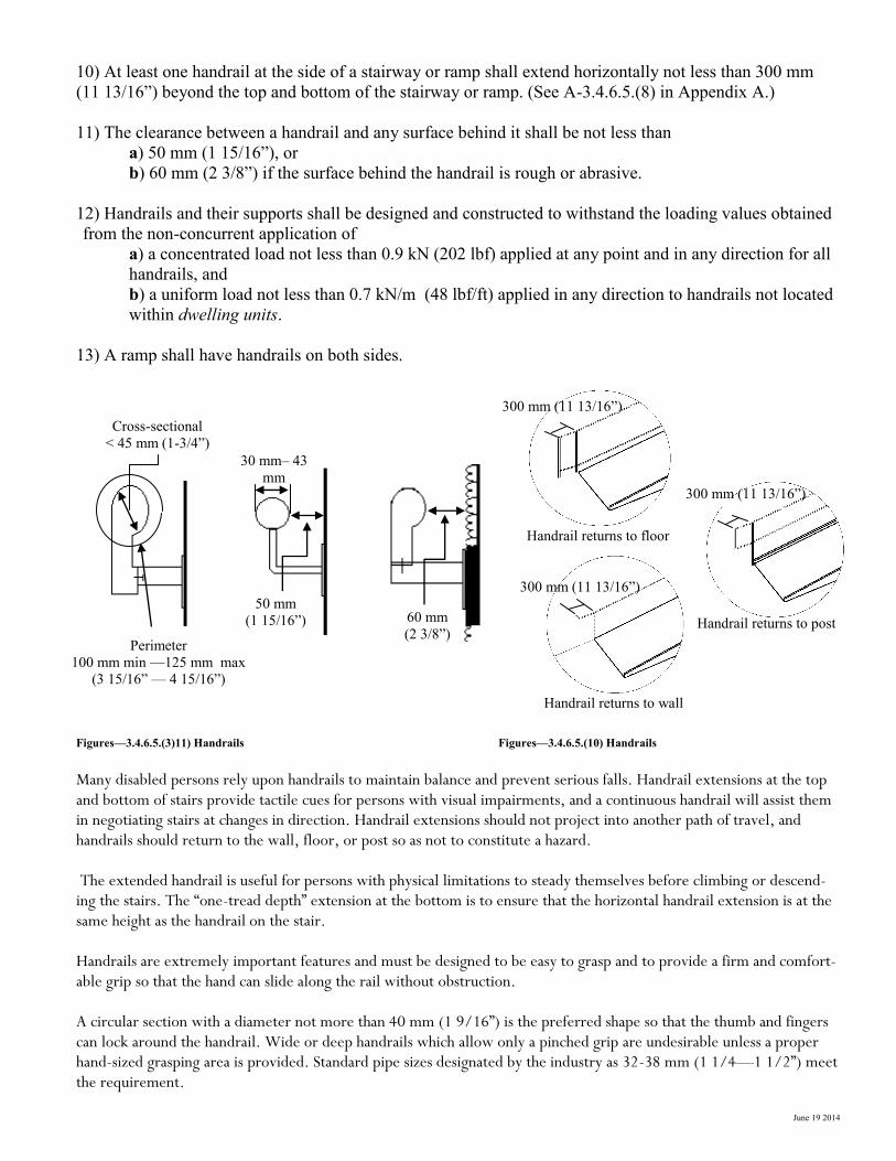
3) Handrails shall be continuously graspable along their entire length and shall have
a) a circular cross-section with an outside diameter not less than 30 mm (1 3/16”) and not more than
43 mm (1 11/16”), or
b) a non-circular cross-section with a graspable portion that has a perimeter not less than 100 mm
(3 15/16”) and not more than 125 mm (4 15/16”) and whose largest cross-sectional dimension is not
more than 45 mm (1 3/4”).
4) The height of handrails on stairs and ramps shall be measured vertically from the top of the handrail to
a) a straight line drawn tangent to the tread nosings of the stair served by the handrail (see A-9.8.7.4. in
Appendix A), or
b) the surface of the ramp, floor or landing served by the handrail.
5) Except as provided in Sentences (6) and (7), the height of handrails on stairs and ramps shall be
a) not less than 865 mm (34”), and
b) not more than 965 mm (38”).
6) Handrails installed in addition to required handrails need not comply with Sentence (5).
7) Where guards are required, handrails on landings shall be not more than 1 070 mm (42 1/8”) in height.
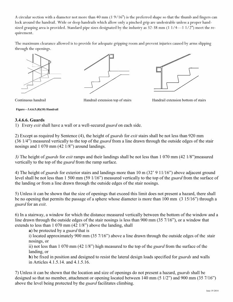
8) Except where interrupted by doorways or newels at changes in direction, at least one handrail shall be
continuous throughout the length of a stairway or ramp, including landings. (See Appendix A.)
9) Handrails shall be terminated in a manner which will not obstruct pedestrian travel or create a hazard.
(See A-3.4.6.5.(8) in Appendix A
1500 mm
(59 1/16”) min 1500 mm min
1200 mm
(47 1/4”) min 9.0 m max
1:12 Incline 1:12 Incline
9.0 m (29’-6”) max
June 19 2014
Perimeter
100 mm min —125 mm max
(3 15/16” — 4 15/16”)
Cross-sectional
< 45 mm (1-3/4”)
30 mm– 43
mm
50 mm
(1 15/16”)
60 mm
(2 3/8”)
10) At least one handrail at the side of a stairway or ramp shall extend horizontally not less than 300 mm
(11 13/16”) beyond the top and bottom of the stairway or ramp. (See A-3.4.6.5.(8) in Appendix A.)
11) The clearance between a handrail and any surface behind it shall be not less than
a) 50 mm (1 15/16”), or
b) 60 mm (2 3/8”) if the surface behind the handrail is rough or abrasive.
12) Handrails and their supports shall be designed and constructed to withstand the loading values obtained
from the non-concurrent application of
a) a concentrated load not less than 0.9 kN (202 lbf) applied at any point and in any direction for all
handrails, and
b) a uniform load not less than 0.7 kN/m (48 lbf/ft) applied in any direction to handrails not located
within dwelling units.
13) A ramp shall have handrails on both sides.
Figures—3.4.6.5.(3)11) Handrails Figures—3.4.6.5.(10) Handrails
Many disabled persons rely upon handrails to maintain balance and prevent serious falls. Handrail extensions at the top and bottom of stairs provide tactile cues for persons with visual impairments, and a continuous handrail will assist them in negotiating stairs at changes in direction. Handrail extensions should not project into another path of travel, and handrails should return to the wall, floor, or post so as not to constitute a hazard. The extended handrail is useful for persons with physical limitations to steady themselves before climbing or descend-ing the stairs. The “one-tread depth” extension at the bottom is to ensure that the horizontal handrail extension is at the same height as the handrail on the stair. Handrails are extremely important features and must be designed to be easy to grasp and to provide a firm and comfort-able grip so that the hand can slide along the rail without obstruction. A circular section with a diameter not more than 40 mm (1 9/16”) is the preferred shape so that the thumb and fingers can lock around the handrail. Wide or deep handrails which allow only a pinched grip are undesirable unless a proper hand-sized grasping area is provided. Standard pipe sizes designated by the industry as 32-38 mm (1 1/4—1 1/2”) meet the requirement.
300 mm (11 13/16”)
300 mm (11 13/16”)
300 mm (11 13/16”)
Handrail returns to floor
Handrail returns to post
Handrail returns to wall
June 19 2014
A circular section with a diameter not more than 40 mm (1 9/16”) is the preferred shape so that the thumb and fingers can lock around the handrail. Wide or deep handrails which allow only a pinched grip are undesirable unless a proper hand-sized grasping area is provided. Standard pipe sizes designated by the industry as 32-38 mm (1 1/4—1 1/2”) meet the re-quirement. The maximum clearance allowed is to provide for adequate gripping room and prevent injuries caused by arms slipping through the openings.
Continuous handrail Handrail extension top of stairs Handrail extension bottom of stairs
Figure—3.4.6.5.(8)(10) Handrail
3.4.6.6. Guards
1) Every exit shall have a wall or a well-secured guard on each side.
2) Except as required by Sentence (4), the height of guards for exit stairs shall be not less than 920 mm
(36 1/4”) measured vertically to the top of the guard from a line drawn through the outside edges of the stair
nosings and 1 070 mm (42 1/8”) around landings.
3) The height of guards for exit ramps and their landings shall be not less than 1 070 mm (42 1/8”)measured
vertically to the top of the guard from the ramp surface.
4) The height of guards for exterior stairs and landings more than 10 m (32’ 9 11/16”) above adjacent ground
level shall be not less than 1 500 mm (59 1/16”) measured vertically to the top of the guard from the surface of
the landing or from a line drawn through the outside edges of the stair nosings.
5) Unless it can be shown that the size of openings that exceed this limit does not present a hazard, there shall
be no opening that permits the passage of a sphere whose diameter is more than 100 mm (3 15/16”) through a
guard for an exit.
6) In a stairway, a window for which the distance measured vertically between the bottom of the window and a
line drawn through the outside edges of the stair nosings is less than 900 mm (35 7/16”), or a window that
extends to less than 1 070 mm (42 1/8”) above the landing, shall
a) be protected by a guard that is
i) located approximately 900 mm (35 7/16”) above a line drawn through the outside edges of the stair
nosings, or
ii) not less than 1 070 mm (42 1/8”) high measured to the top of the guard from the surface of the
landing, or
b) be fixed in position and designed to resist the lateral design loads specified for guards and walls
in Articles 4.1.5.14. and 4.1.5.16.
7) Unless it can be shown that the location and size of openings do not present a hazard, guards shall be
designed so that no member, attachment or opening located between 140 mm (5 1/2”) and 900 mm (35 7/16”)
above the level being protected by the guard facilitates climbing.
June 19 2014
4.1.5.14. Loads on Guards
(See Appendix A.)
1) The minimum specified horizontal load applied inward or outward at the minimum required height of every
required guard shall be
a) 3.0 kN/m (206 lbf/ft) for open viewing stands without fixed seats and for means of egress in
grandstands, stadia, bleachers and arenas,
b) a concentrated load of 1.0 kN (225 lbf) applied at any point for access ways to equipment
platforms,
contiguous stairs and similar areas where the gathering of many people is improbable, and
c) 0.75 kN/m (52 lbf/ft) or a concentrated load of 1.0 kN (225lbf) applied at any point, whichever
governs for locations other than those described in Clauses (a) and (b).
2) Individual elements within the guard, including solid panels and pickets, shall be designed for a load of
0.5 kN (112lbf) applied over an area of 100 mm (3 15/16”) by 100 mm (3 15/16”) located at any point in the
element or elements so as to produce the most critical effect.
3) The loads required in Sentence (2) need not be considered to act simultaneously with the loads provided for
in Sentences (1) and (4).
4) The minimum specified load applied vertically at the top of every required guard shall be 1.5 kN/m
(103 lbf/ft) and need not be considered to act simultaneously with the horizontal load provided for in
sentence (1).
5) For loads on handrails, refer to Sentence 3.4.6.5.(12).
A-4.1.5.14. and 4.1.5.15.(1) Design of Guards. In the design of guards, due consideration should be given to the durability of the members and their connections.
4.1.5.16. Loads on Walls Acting As Guards
1) Where the floor elevation on one side of a wall, including a wall around a shaft, is more than 600 mm
(23 5/8”) higher than the elevation of the floor or ground on the other side, the wall shall be designed to
resist the appropriate lateral design loads prescribed elsewhere in this Section or 0.5 kPa (11 psf),
whichever produces the more critical effect.
3.8.3.5. Passenger-elevating devices
1) A passenger-elevating device referred to in Article 3.8.2.1. shall conform to CAN/CSA-B355, “Lifts for
Persons with Physical Disabilities.”
All elevator and passenger lift controls, special call buttons, emergency phones and speakers should be mounted at heights which are usable by persons in wheelchairs. In addition the elevator or passenger lift should be able to be safely operated by disabled persons.

June 19 2014
3.8.3.6. Spaces in Seating Area
1) Spaces designated for wheelchair use referred to in Sentence 3.8.2.1.(3) shall be
a) clear and level, or level with removable seats,
b) not less than 900 mm (35 7/16”) wide and 1 525 mm (60 1/16”) long to permit a wheelchair to enter
from a side approach and 1 220 mm (48 1/8”) long where the wheelchair enters from the front or rear
of the space,
c) arranged so that at least 2 designated spaces are side by side,
d) located adjoining a barrier-free path of travel without infringing on egress from any row of seating
or any aisle requirements, and
e) situated, as part of the designated seating plan, to provide a choice of viewing location and a clear
view of the event taking place.
In auditoriums, level areas should be provided for wheelchair users, large enough to accommodate two wheelchairs side by side, or persons using leg braces. Spaces should be located on each accessible level and in a variety of price categories. Such spaces should not obstruct the required aisles or exiting widths.
3.8.3.6 Spaces in Seating Area
Figure—3.8.3.6. Spaces in Seating Area
3.8.3.7. Assistive Listening Devices
(See Appendix A.)
1) Except as permitted by Sentence (2), in a building of assembly occupancy, all classrooms, auditoria,
meeting rooms and theatres with an area of more than 100 m2 (1077 ft2 ) shall be equipped with an assis-
tive listening system encompassing the entire seating area.
2) If the assistive listening system required by Sentence (1) is an induction loop system, only half the seating
area in the room need be encompassed.
Accessible Route
Accessible Route
1220 mm (48 1/8”)
90
0 m
m (3
5 7
/16
”)
1525 mm (60 1/16”)
Forward/Rear and side
approach to wheelchair
seating space

June 19 2014
A-3.8.3.7. Assistive Listening Systems. Wireless sound transmission systems, including FM, infrared or magnetic induction loop sys-tems, improve sound reception for persons with hearing disabilities by providing amplification which can be adjusted by each user while blocking out unwanted background noise. These systems transmit a signal that is picked up by a special receiver available for use by a person with a hearing disability, whether or not a hearing aid is used. Neither system interferes with the listening enjoyment of others. The transmitter can be jacked into an existing P.A. system amplifier or used independently with microphones. The induction loop system requires users to sit in the area circumscribed by the loop; though installation of the loop is relatively simple, the installer should be knowledgeable about these systems if proper functioning is to be achieved. FM or infrared systems can be designed to broadcast signals which cover the entire room and thus do not restrict seating to any one area. Figures A-3.8.3.7.-A and A-3.8.3.7.-B show the general configuration of FM and infrared systems. Although portable systems (FM in particular) are available, these are best suited to small audiences. Generally, the systems installed in church halls, auditoria, theatres and similar places of assembly are not easily portable, as they are installed in a fixed location by a sound technician and form an integral part of the P.A. system of the room or building. Hard-wired systems (where a jack is provided at a particular seat) will not meet this requirement unless adequate provisions are made to accommodate persons with hearing aids. In choosing the most appropriate system, a number of factors must be taken into account including cost, installation and maintenance, suitability to the audience, ease of operation and the need for privacy. Information on designers and suppliers of these systems may be obtained from the Canadian Hearing Society.
Figure A-3.8.3.7.A FM sound transmission system Figure A-3.8.3.7.B Infrared sound transmission system
Microphone, Tape, T.V. , Film etc. Microphone, Tape, T.V. , Film etc.
Amplifier
Amplifier
FM Transmitter
FM Receiver
No
rmal
So
und
Syst
em
No
rmal
So
und
Syst
em
FM
Bro
adca
st
Syst
em
Infr
ared
S
yst
em
Infrared Control
Transmitter
Speakers
Speakers
Infrared Radiator (one or more)
Infrared Light Waves
Infrared Receiver

June 19 2014
3.8.3.8. Water Closet Stalls
1) At least one water closet stall or enclosure in a washroom required by Article 3.8.2.3. to be barrier-free
shall
a) be not less than 1 500 mm (59 1/16”) wide by 1 500 mm (59 1/16”) deep,
b) be equipped with a door that
i) can be latched from the inside with a closed fist,
ii) provides a clear opening not less than 800 mm (31 1/2”) wide when it is open,
iii) swings outward, unless sufficient room is provided within the stall or enclosure to permit the door
to be closed without interfering with the wheelchair (see Appendix A),
iv) is provided on the inside with a door pull not less than 140 mm (5 1/2”) long located so that its
midpoint is not less than 200 mm (7 7/8”) and not more than 300 mm (11 13/16”) from the hinged side
the door and not less than 900 mm (35 7/16”) and not more than 1 000 mm (39 3/8”) above the floor
(see Appendix A), and
v) is provided with a door pull on the outside, near the latch side of the door,
c) have a water closet located so that the clearance between the fixture and the wall on one side is not
less than 285 mm (11 1/4”) and not more than 305 mm (12”),
d) be equipped with grab bars that
i) are mounted horizontally on the side wall closest to the water closet and shall extend not less than
450 mm (17 11/16”) in both directions from the most forward point of the water closet
(see Appendix A),
ii) if the water closet does not have an attached water tank, are at least 600 mm (23 5/8”) in length,
mounted horizontally on the wall behind the water closet and centred on the toilet bowl,
iii) are mounted not less than 840 mm (33 1/16”) and not more than 920 mm (36 1/4”) above the floor,
iv) are installed to resist a load of not less than 1.3 kN (292 lbf) applied vertically or horizontally,
v) are not less than 30 mm (1 3/16”) and not more than 40 mm (1 9/16”) in diameter, and
vi) have a clearance of not less than 35 mm (1 3/8”) and not more than 45 mm (1 3/4”) from the wall,
e) be equipped with a coat hook mounted not more than 1 200 mm (47 1/4”) above the floor on a side
wall and projecting not more than 50 mm (1 15/16”) from the wall, and
f) have a clearance of not less than 1 700 mm (66 15/16”) between the outside of the stall face and the
face of an in-swinging washroom door and 1 400 mm (55 1/8”) between the outside of the stall face
and any wall-mounted fixture.
A-3.8.3.8.(1)(b)(iii) Water Closet Stalls. Doors to water closet stalls for persons with physical disabilities should swing outward, preferably against a side wall. Figure A-3.8.3.8.(1)(b)(iii).A Water Closet Stalls
wall mounted
fixture
17
00
mm
(66
15
/16
”)
14
00
mm
(55
1/8
”)
June 19 2014
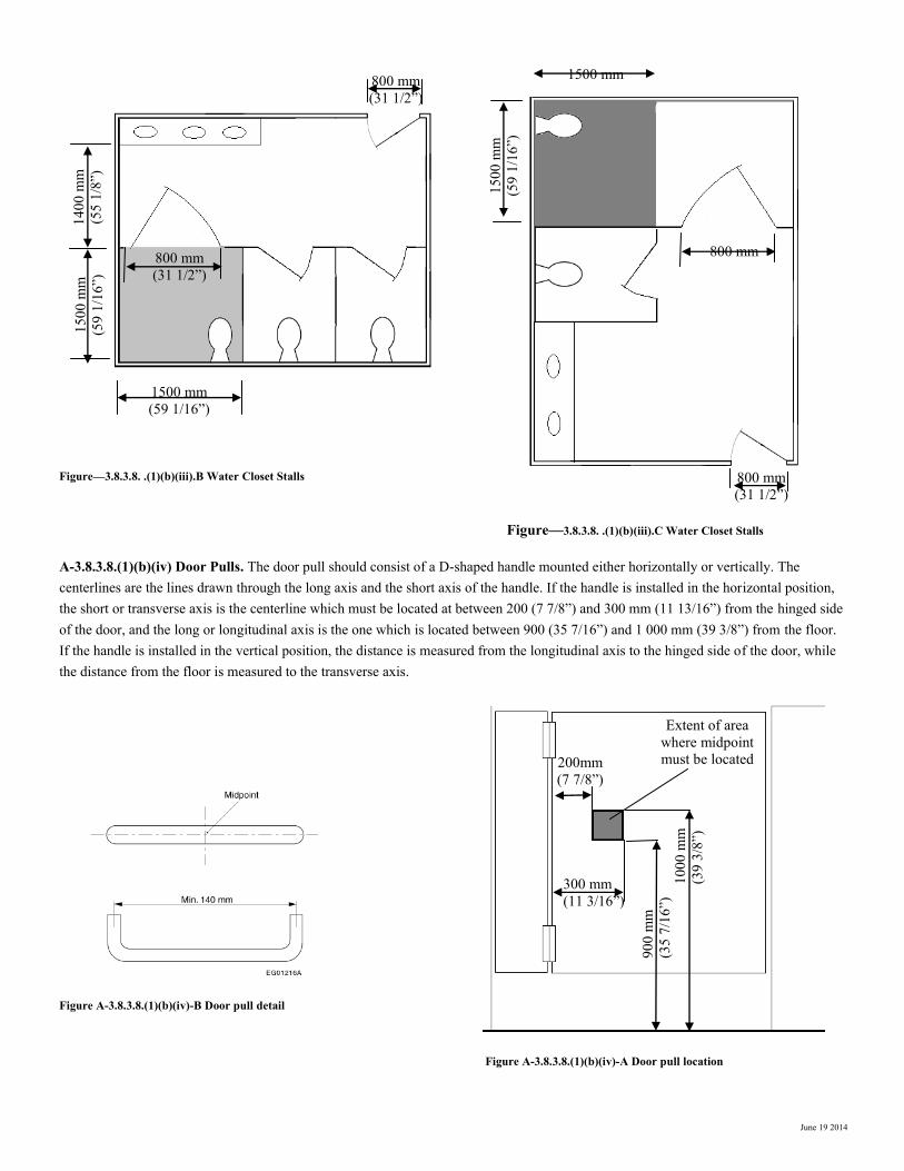
Figure—3.8.3.8. .(1)(b)(iii).B Water Closet Stalls
Figure—3.8.3.8. .(1)(b)(iii).C Water Closet Stalls
A-3.8.3.8.(1)(b)(iv) Door Pulls. The door pull should consist of a D-shaped handle mounted either horizontally or vertically. The centerlines are the lines drawn through the long axis and the short axis of the handle. If the handle is installed in the horizontal position, the short or transverse axis is the centerline which must be located at between 200 (7 7/8”) and 300 mm (11 13/16”) from the hinged side of the door, and the long or longitudinal axis is the one which is located between 900 (35 7/16”) and 1 000 mm (39 3/8”) from the floor. If the handle is installed in the vertical position, the distance is measured from the longitudinal axis to the hinged side of the door, while the distance from the floor is measured to the transverse axis. Figure A-3.8.3.8.(1)(b)(iv)-B Door pull detail
Figure A-3.8.3.8.(1)(b)(iv)-A Door pull location
1500 mm
15
00
mm
(59
1/1
6”)
800 mm
(31 1/2”)
800 mm
1500 mm
(59 1/16”)
15
00
mm
(59
1/1
6”)
14
00
mm
(55
1/8
”)
800 mm
(31 1/2”)
800 mm
(31 1/2”)
200mm
(7 7/8”)
90
0 m
m
(35
7/1
6”)
1
00
0 m
m
(39
3/8
”)
300 mm
(11 3/16”)
Extent of area
where midpoint
must be located
June 19 2014
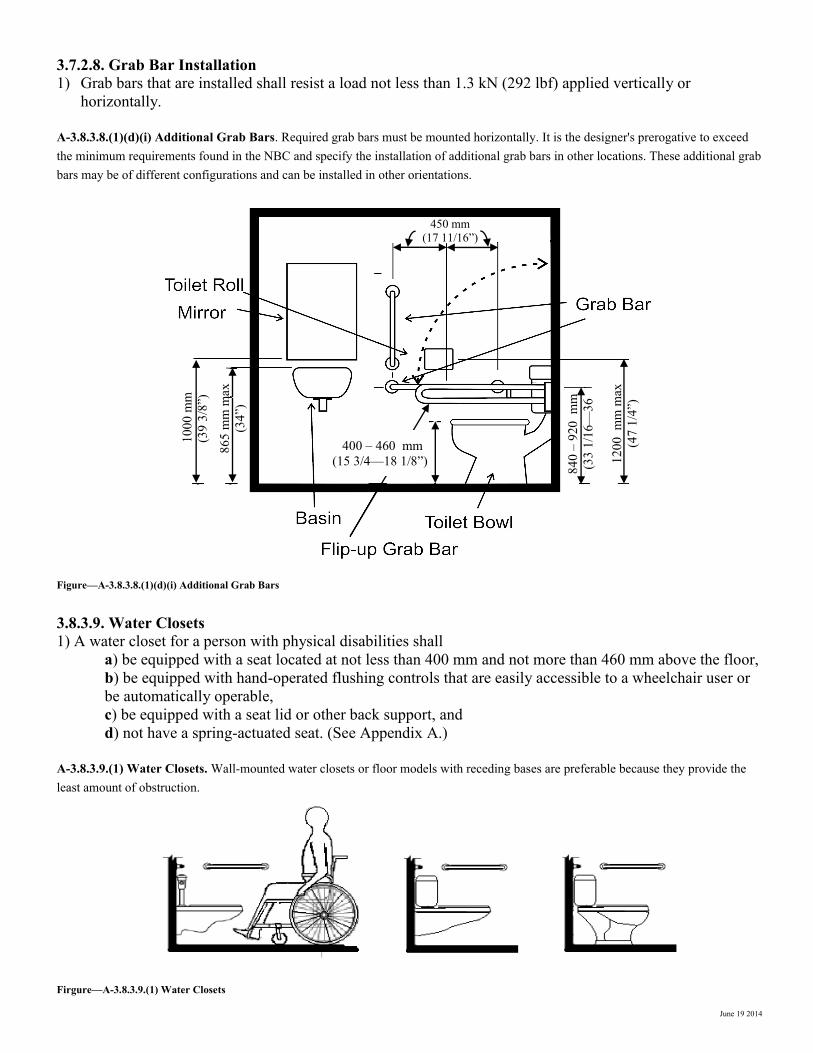
3.7.2.8. Grab Bar Installation
1) Grab bars that are installed shall resist a load not less than 1.3 kN (292 lbf) applied vertically or
horizontally. A-3.8.3.8.(1)(d)(i) Additional Grab Bars. Required grab bars must be mounted horizontally. It is the designer's prerogative to exceed the minimum requirements found in the NBC and specify the installation of additional grab bars in other locations. These additional grab bars may be of different configurations and can be installed in other orientations. Figure—A-3.8.3.8.(1)(d)(i) Additional Grab Bars
3.8.3.9. Water Closets
1) A water closet for a person with physical disabilities shall
a) be equipped with a seat located at not less than 400 mm and not more than 460 mm above the floor,
b) be equipped with hand-operated flushing controls that are easily accessible to a wheelchair user or
be automatically operable,
c) be equipped with a seat lid or other back support, and
d) not have a spring-actuated seat. (See Appendix A.) A-3.8.3.9.(1) Water Closets. Wall-mounted water closets or floor models with receding bases are preferable because they provide the least amount of obstruction.
Firgure—A-3.8.3.9.(1) Water Closets
10
00
mm
400 – 460 mm
(15 3/4—18
1/8”)
84
0 –
920
m
m
(33
1/1
6—
36
450 mm
(17 11/16”)
12
00
m
m m
ax
(47
1/4
”)
86
5 m
m m
ax
(34
”)
10
00
mm
(39
3/8
”)
84
0 –
920
m
m
(33
1/1
6—
36
450 mm
(17 11/16”)
12
00
m
m m
ax
(47
1/4
”)
86
5 m
m m
ax
(34
”)
400 – 460 mm
(15 3/4—18 1/8”)
June 19 2014
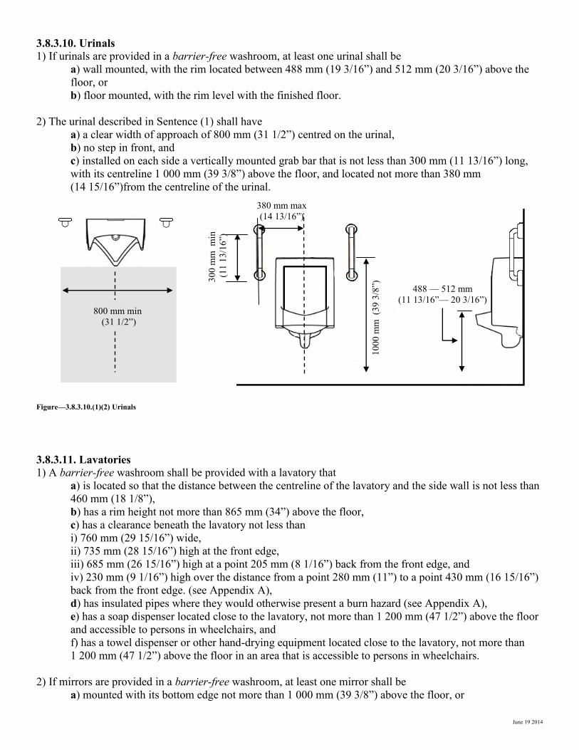
3.8.3.10. Urinals
1) If urinals are provided in a barrier-free washroom, at least one urinal shall be
a) wall mounted, with the rim located between 488 mm (19 3/16”) and 512 mm (20 3/16”) above the
floor, or
b) floor mounted, with the rim level with the finished floor.
2) The urinal described in Sentence (1) shall have
a) a clear width of approach of 800 mm (31 1/2”) centred on the urinal,
b) no step in front, and
c) installed on each side a vertically mounted grab bar that is not less than 300 mm (11 13/16”) long,
with its centreline 1 000 mm (39 3/8”) above the floor, and located not more than 380 mm
(14 15/16”)from the centreline of the urinal.
Figure—3.8.3.10.(1)(2) Urinals
3.8.3.11. Lavatories
1) A barrier-free washroom shall be provided with a lavatory that
a) is located so that the distance between the centreline of the lavatory and the side wall is not less than
460 mm (18 1/8”),
b) has a rim height not more than 865 mm (34”) above the floor,
c) has a clearance beneath the lavatory not less than
i) 760 mm (29 15/16”) wide,
ii) 735 mm (28 15/16”) high at the front edge,
iii) 685 mm (26 15/16”) high at a point 205 mm (8 1/16”) back from the front edge, and
iv) 230 mm (9 1/16”) high over the distance from a point 280 mm (11”) to a point 430 mm (16 15/16”)
back from the front edge. (see Appendix A),
d) has insulated pipes where they would otherwise present a burn hazard (see Appendix A),
e) has a soap dispenser located close to the lavatory, not more than 1 200 mm (47 1/2”) above the floor
and accessible to persons in wheelchairs, and
f) has a towel dispenser or other hand-drying equipment located close to the lavatory, not more than
1 200 mm (47 1/2”) above the floor in an area that is accessible to persons in wheelchairs.
2) If mirrors are provided in a barrier-free washroom, at least one mirror shall be
a) mounted with its bottom edge not more than 1 000 mm (39 3/8”) above the floor, or
800 mm min
(31 1/2”)
10
00
mm
(3
9 3
/8”)
30
0 m
m
min
(1
1 1
3/1
6”)
380 mm max
(14 13/16”)
488 — 512 mm
(11 13/16”— 20 3/16”)
June 19 2014
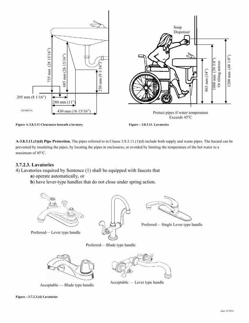
Figure A-3.8.3.11 Clearances beneath a lavatory Figure—3.8.3.11. Lavatories
A-3.8.3.11.(1)(d) Pipe Protection. The pipes referred to in Clause 3.8.3.11.(1)(d) include both supply and waste pipes. The hazard can be prevented by insulating the pipes, by locating the pipes in enclosures, or avoided by limiting the temperature of the hot water to a maximum of 45°C.
3.7.2.3. Lavatories
4) Lavatories required by Sentence (1) shall be equipped with faucets that
a) operate automatically, or
b) have lever-type handles that do not close under spring action.
Figure—3.7.2.3.(4) Lavatories
205 mm (8 1/16”)
280 mm (11”)
430 mm (16 15/16”)
73
5 m
m
(28
15
/16
”)
68
5 m
m (
26
15
/16
”)
23
0 m
m (
9 1
/16
”)
GC00053A
10
00
mm
(3
9 3
/8”)
Or
tilt
ing m
irro
r
86
5 m
m (
34
”)
Protect pipes if water temperature
Exceeds 45oC
12
00
mm
(4
8 1
/8”)
Soap
Dispenser
Preferred— Single Lever type handle
Acceptable — Lever type handle
Preferred— Blade type handle
Acceptable — Blade type handle
Preferred— Lever type handle
June 19 2014
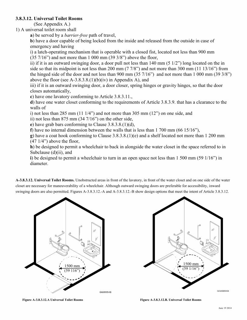
3.8.3.12. Universal Toilet Rooms
(See Appendix A.)
1) A universal toilet room shall
a) be served by a barrier-free path of travel,
b) have a door capable of being locked from the inside and released from the outside in case of
emergency and having
i) a latch-operating mechanism that is operable with a closed fist, located not less than 900 mm
(35 7/16”) and not more than 1 000 mm (39 3/8”) above the floor,
ii) if it is an outward swinging door, a door pull not less than 140 mm (5 1/2”) long located on the in
side so that its midpoint is not less than 200 mm (7 7/8”) and not more than 300 mm (11 13/16”) from
the hinged side of the door and not less than 900 mm (35 7/16”) and not more than 1 000 mm (39 3/8”)
above the floor (see A-3.8.3.8.(1)(b)(iv) in Appendix A), and
iii) if it is an outward swinging door, a door closer, spring hinges or gravity hinges, so that the door
closes automatically,
c) have one lavatory conforming to Article 3.8.3.11.,
d) have one water closet conforming to the requirements of Article 3.8.3.9. that has a clearance to the
walls of
i) not less than 285 mm (11 1/4”) and not more than 305 mm (12”) on one side, and
ii) not less than 875 mm (34 7/16”) on the other side,
e) have grab bars conforming to Clause 3.8.3.8.(1)(d),
f) have no internal dimension between the walls that is less than 1 700 mm (66 15/16”),
g) have a coat hook conforming to Clause 3.8.3.8.(1)(e) and a shelf located not more than 1 200 mm
(47 1/4”) above the floor,
h) be designed to permit a wheelchair to back in alongside the water closet in the space referred to in
Subclause (d)(ii), and
i) be designed to permit a wheelchair to turn in an open space not less than 1 500 mm (59 1/16”) in
diameter. A-3.8.3.12. Universal Toilet Rooms. Unobstructed areas in front of the lavatory, in front of the water closet and on one side of the water closet are necessary for maneuverability of a wheelchair. Although outward swinging doors are preferable for accessibility, inward swinging doors are also permitted. Figures A-3.8.3.12.-A and A-3.8.3.12.-B show design options that meet the intent of Article 3.8.3.12.
Figure A-3.8.3.12.A Universal Toilet Rooms Figure A-3.8.3.12.B. Universal Toilet Rooms
1500 mm
(59 116”)
1500 mm
(59 1/16”)

June 19 2014
3.8.3.13. Showers
1) Except within a suite of care occupancy or a suite of residential occupancy, where showers are provided in
a building, at least one shower stall in each group of showers shall be barrier-free and shall
a) be not less than 1 500 mm (59 1/16”) wide and 900 mm (35 7/16”) deep,
b) have a clear floor space at the entrance to the shower, not less than 900 mm (35 7/16”) deep and the
same width as the shower, except that fixtures are permitted to project into that space provided they do
not restrict access to the shower (see Appendix A),
c) have a slip-resistant floor surface,
d) have a bevelled threshold not more than 13 mm (1/2”) higher than the finished floor,
e) have a hinged seat that is not spring-loaded or a fixed seat, the seat being
i) not less than 450 mm (17 11/16”) wide and 400 mm (15 3/4”) deep,
ii) mounted approximately 450 mm 17 11/16”) above the floor, and
iii) designed to carry a minimum load of 1.3 kN (292 lbf),
f) have a horizontal grab bar conforming to Subclauses 3.8.3.8.(1)(d)(iv), (d)(v) and (d)(vi) that is
(see Appendix A)
i) not less than 900 mm (35 7/16”) long,
ii) mounted between 700 mm (27 9/16”) and 800 mm (31 1/2”) above the floor, and
iii) located on the wall opposite the entrance to the shower so that not less than 300 mm (11 13/16”) of
ts length is at one side of the seat,
g) have a pressure-equalizing or thermostatic-mixing valve controlled by a lever or other device
operable with a closed fist from the seated position,
h) have a hand-held shower head with not less than 1 500 mm (59 1/16”) of flexible hose located so
that it can be reached from the seated position and equipped with a holder so that it can operate as a
fixed shower head, and
i) have fully recessed soap holders that can be reached from the seated position.
Figure—3.8.3.13.1. Showers
A-3.8.3.13.(1)(b) Clear Space at Entrances to Showers. The clear space at the entrance to a shower may be encroached upon by fixtures such as a wall hung sink which does not interfere with the leg rests of the wheelchair. However, this sink could restrict movement for persons who need to make a lateral transfer if it were installed at the seat end of the shower. A-3.8.3.13.(1)(f) Grab Bars. One horizontal grab bar is required to be installed on the wall next to the seat. A grab bar behind the seat would prevent the user from leaning back against the wall, while one located on the wall opposite the seat cannot be reached from the seated position. The seat itself may be used in conjunction with the bar for transfer. If design flexibility is required, fold away grab bars
can be used as an alternative.
900 mm min
(35 7/16”)
1500 mm m
in
(59 15/16”)
Hand-held shower
head with 1500 mm
(59 1/16”)
Recessed soap dish
900 mm min
(35 7/16”)
900 mm m
in
(35 7/16”)
700—800 mm
(27 9/16” - 31 1/2”)
450 mm min
(17 11/16”)
400 mm m
in
(15 3/4”) 450 mm
(17 11/16”)
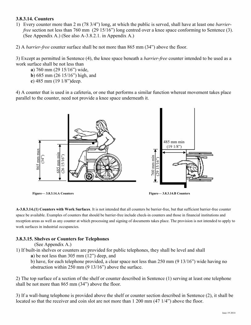
June 19 2014
3.8.3.14. Counters
1) Every counter more than 2 m (78 3/4”) long, at which the public is served, shall have at least one barrier-
free section not less than 760 mm (29 15/16”) long centred over a knee space conforming to Sentence (3).
(See Appendix A.) (See also A-3.8.2.1. in Appendix A.)
2) A barrier-free counter surface shall be not more than 865 mm (34”) above the floor.
3) Except as permitted in Sentence (4), the knee space beneath a barrier-free counter intended to be used as a
work surface shall be not less than
a) 760 mm (29 15/16”) wide,
b) 685 mm (26 15/16”) high, and
c) 485 mm (19 1/8”)deep.
4) A counter that is used in a cafeteria, or one that performs a similar function whereat movement takes place
parallel to the counter, need not provide a knee space underneath it.
Figure— 3.8.3.14.A Counters Figure— 3.8.3.14.B Counters
A-3.8.3.14.(1) Counters with Work Surfaces. It is not intended that all counters be barrier-free, but that sufficient barrier-free counter space be available. Examples of counters that should be barrier-free include check-in counters and those in financial institutions and reception areas as well as any counter at which processing and signing of documents takes place. The provision is not intended to apply to work surfaces in industrial occupancies.
3.8.3.15. Shelves or Counters for Telephones
(See Appendix A.)
1) If built-in shelves or counters are provided for public telephones, they shall be level and shall
a) be not less than 305 mm (12”) deep, and
b) have, for each telephone provided, a clear space not less than 250 mm (9 13/16”) wide having no
obstruction within 250 mm (9 13/16”) above the surface.
2) The top surface of a section of the shelf or counter described in Sentence (1) serving at least one telephone
shall be not more than 865 mm (34”) above the floor.
3) If a wall-hung telephone is provided above the shelf or counter section described in Sentence (2), it shall be
located so that the receiver and coin slot are not more than 1 200 mm (47 1/4”) above the floor.
68
5 m
m m
in
(26
15
/16
”)
485 mm min
(19 1/8”)
86
5 m
m m
ax
(34
”)
76
0 m
m m
in
(29
15
/16
”)
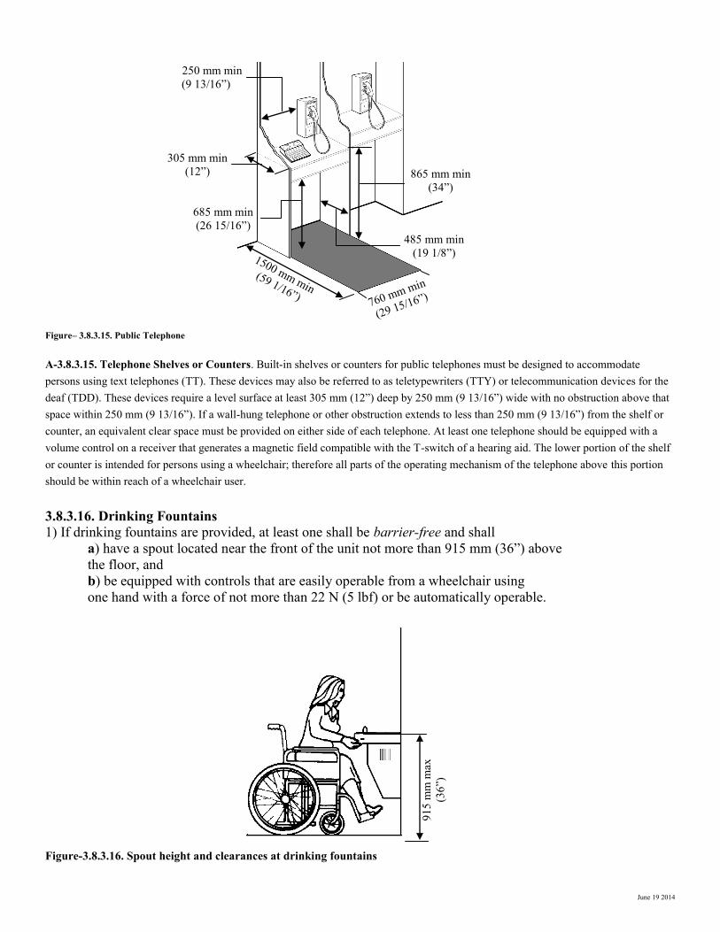
June 19 2014
Figure– 3.8.3.15. Public Telephone
A-3.8.3.15. Telephone Shelves or Counters. Built-in shelves or counters for public telephones must be designed to accommodate persons using text telephones (TT). These devices may also be referred to as teletypewriters (TTY) or telecommunication devices for the deaf (TDD). These devices require a level surface at least 305 mm (12”) deep by 250 mm (9 13/16”) wide with no obstruction above that space within 250 mm (9 13/16”). If a wall-hung telephone or other obstruction extends to less than 250 mm (9 13/16”) from the shelf or counter, an equivalent clear space must be provided on either side of each telephone. At least one telephone should be equipped with a volume control on a receiver that generates a magnetic field compatible with the T-switch of a hearing aid. The lower portion of the shelf or counter is intended for persons using a wheelchair; therefore all parts of the operating mechanism of the telephone above this portion should be within reach of a wheelchair user.
3.8.3.16. Drinking Fountains
1) If drinking fountains are provided, at least one shall be barrier-free and shall
a) have a spout located near the front of the unit not more than 915 mm (36”) above
the floor, and
b) be equipped with controls that are easily operable from a wheelchair using
one hand with a force of not more than 22 N (5 lbf) or be automatically operable.
Figure-3.8.3.16. Spout height and clearances at drinking fountains
91
5 m
m m
ax
(36
”)
250 mm min
(9 13/16”)
305 mm min
(12”)
1500 mm min
(59 1/16”) 760 mm min
(29 15/16”)
685 mm min
(26 15/16”)
485 mm min
(19 1/8”)
865 mm min
(34”)
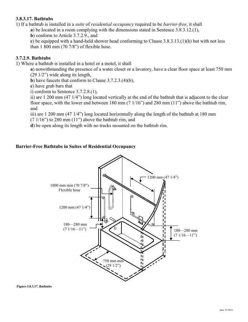
June 19 2014
3.8.3.17. Bathtubs
1) If a bathtub is installed in a suite of residential occupancy required to be barrier-free, it shall
a) be located in a room complying with the dimensions stated in Sentence 3.8.3.12.(1),
b) conform to Article 3.7.2.9., and
c) be equipped with a hand-held shower head conforming to Clause 3.8.3.13.(1)(h) but with not less
than 1 800 mm (70 7/8”) of flexible hose.
3.7.2.9. Bathtubs
1) Where a bathtub is installed in a hotel or a motel, it shall
a) notwithstanding the presence of a water closet or a lavatory, have a clear floor space at least 750 mm
(29 1/2”) wide along its length,
b) have faucets that conform to Clause 3.7.2.3.(4)(b),
c) have grab bars that
i) conform to Sentence 3.7.2.8.(1),
ii) are 1 200 mm (47 1/4”) long located vertically at the end of the bathtub that is adjacent to the clear
floor space, with the lower end between 180 mm (7 1/16”) and 280 mm (11”) above the bathtub rim,
and
iii) are 1 200 mm (47 1/4”) long located horizontally along the length of the bathtub at 180 mm
(7 1/16”) to 280 mm (11”) above the bathtub rim, and
d) be open along its length with no tracks mounted on the bathtub rim.
Barrier-Free Bathtubs in Suites of Residential Occupancy
Figure-3.8.3.17. Bathtubs
1200 mm (47 1/4”)
180—280 mm
(7 1/16—11”)
180—280 mm
(7 1/16—11”)
1800 mm min (70 7/8”)
Flexible hose
750 mm min
(29 1/2”)
1200 mm (47 1/4”)
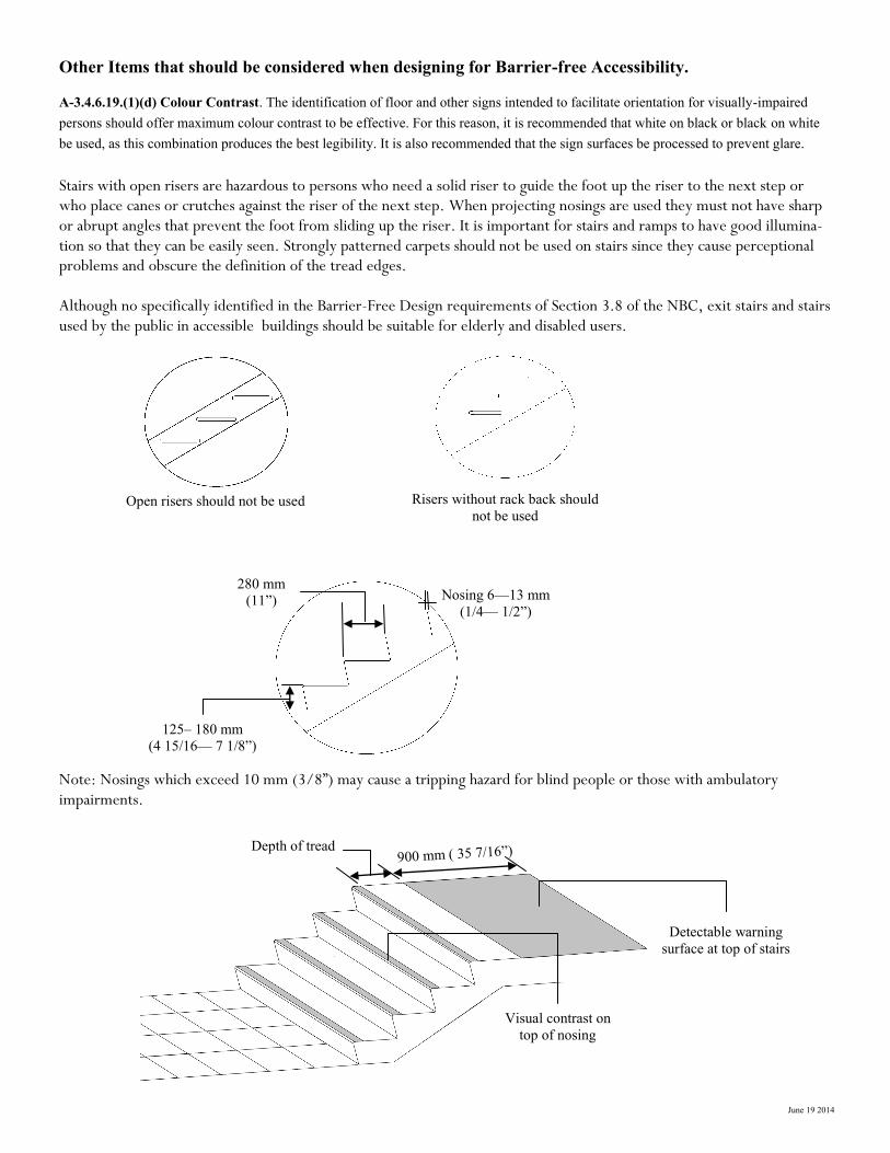
June 19 2014
Other Items that should be considered when designing for Barrier-free Accessibility.
A-3.4.6.19.(1)(d) Colour Contrast. The identification of floor and other signs intended to facilitate orientation for visually-impaired persons should offer maximum colour contrast to be effective. For this reason, it is recommended that white on black or black on white be used, as this combination produces the best legibility. It is also recommended that the sign surfaces be processed to prevent glare.
Stairs with open risers are hazardous to persons who need a solid riser to guide the foot up the riser to the next step or who place canes or crutches against the riser of the next step. When projecting nosings are used they must not have sharp or abrupt angles that prevent the foot from sliding up the riser. It is important for stairs and ramps to have good illumina-tion so that they can be easily seen. Strongly patterned carpets should not be used on stairs since they cause perceptional problems and obscure the definition of the tread edges. Although no specifically identified in the Barrier-Free Design requirements of Section 3.8 of the NBC, exit stairs and stairs used by the public in accessible buildings should be suitable for elderly and disabled users.
Note: Nosings which exceed 10 mm (3/8”) may cause a tripping hazard for blind people or those with ambulatory impairments.
Open risers should not be used
900 mm ( 35 7/16”) Depth of tread
Visual contrast on
top of nosing
Detectable warning
surface at top of stairs
Risers without rack back should
not be used
125– 180 mm
(4 15/16— 7 1/8”)
280 mm
(11”) Nosing 6—13 mm
(1/4— 1/2”)
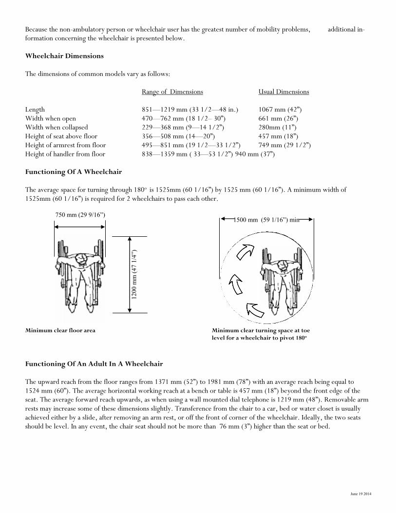
June 19 2014
Because the non-ambulatory person or wheelchair user has the greatest number of mobility problems, additional in-formation concerning the wheelchair is presented below. Wheelchair Dimensions The dimensions of common models vary as follows: Range of Dimensions Usual Dimensions Length 851—1219 mm (33 1/2—48 in.) 1067 mm (42”) Width when open 470—762 mm (18 1/2– 30”) 661 mm (26”) Width when collapsed 229—368 mm (9—14 1/2”) 280mm (11”) Height of seat above floor 356—508 mm (14—20”) 457 mm (18”) Height of armrest from floor 495—851 mm (19 1/2—33 1/2”) 749 mm (29 1/2”) Height of handler from floor 838—1359 mm ( 33—53 1/2”) 940 mm (37”) Functioning Of A Wheelchair The average space for turning through 180o is 1525mm (60 1/16”) by 1525 mm (60 1/16”). A minimum width of 1525mm (60 1/16”) is required for 2 wheelchairs to pass each other.
Minimum clear floor area Minimum clear turning space at toe level for a wheelchair to pivot 180o
Functioning Of An Adult In A Wheelchair The upward reach from the floor ranges from 1371 mm (52”) to 1981 mm (78”) with an average reach being equal to 1524 mm (60”). The average horizontal working reach at a bench or table is 457 mm (18”) beyond the front edge of the seat. The average forward reach upwards, as when using a wall mounted dial telephone is 1219 mm (48”). Removable arm rests may increase some of these dimensions slightly. Transference from the chair to a car, bed or water closet is usually achieved either by a slide, after removing an arm rest, or off the front of corner of the wheelchair. Ideally, the two seats should be level. In any event, the chair seat should not be more than 76 mm (3”) higher than the seat or bed.
12
00
mm
(4
7 1
/4”)
1500 mm (59 1/16”) min 750 mm (29 9/16”)
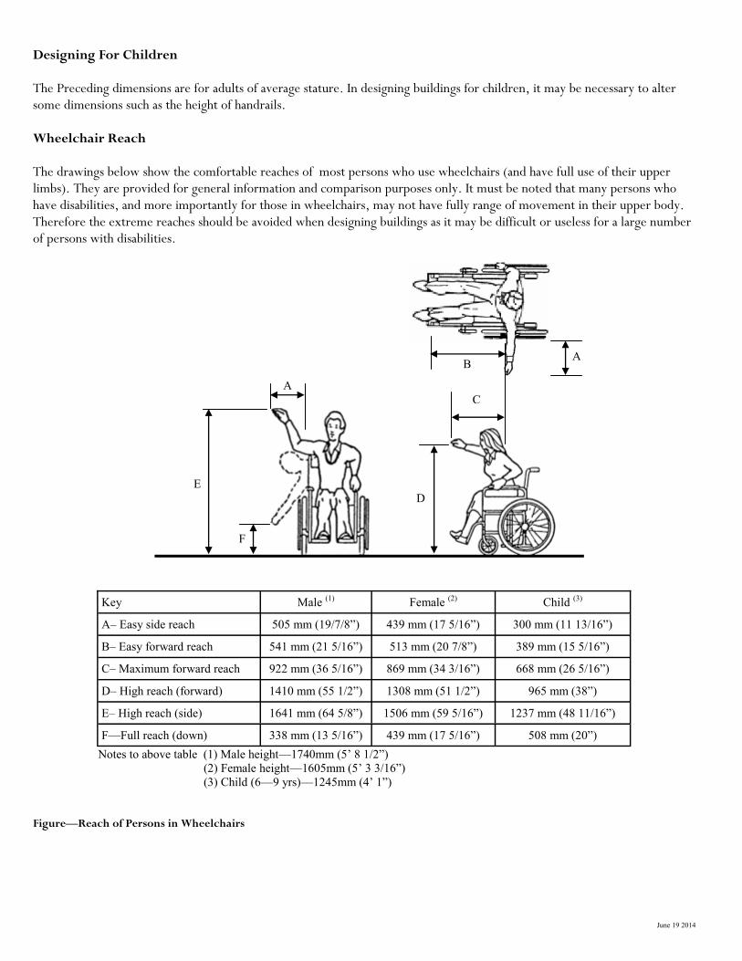
June 19 2014
Designing For Children The Preceding dimensions are for adults of average stature. In designing buildings for children, it may be necessary to alter some dimensions such as the height of handrails. Wheelchair Reach The drawings below show the comfortable reaches of most persons who use wheelchairs (and have full use of their upper limbs). They are provided for general information and comparison purposes only. It must be noted that many persons who have disabilities, and more importantly for those in wheelchairs, may not have fully range of movement in their upper body. Therefore the extreme reaches should be avoided when designing buildings as it may be difficult or useless for a large number of persons with disabilities.
Notes to above table (1) Male height—1740mm (5’ 8 1/2”)
(2) Female height—1605mm (5’ 3 3/16”)
(3) Child (6—9 yrs)—1245mm (4’ 1”)
Figure—Reach of Persons in Wheelchairs
Key Male (1) Female (2) Child (3)
A– Easy side reach 505 mm (19/7/8”) 439 mm (17 5/16”) 300 mm (11 13/16”)
B– Easy forward reach 541 mm (21 5/16”) 513 mm (20 7/8”) 389 mm (15 5/16”)
C– Maximum forward reach 922 mm (36 5/16”) 869 mm (34 3/16”) 668 mm (26 5/16”)
D– High reach (forward) 1410 mm (55 1/2”) 1308 mm (51 1/2”) 965 mm (38”)
E– High reach (side) 1641 mm (64 5/8”) 1506 mm (59 5/16”) 1237 mm (48 11/16”)
F—Full reach (down) 338 mm (13 5/16”) 439 mm (17 5/16”) 508 mm (20”)
C
A B
D
A
E
F

June 19 2014
Notes to above table (1) Male height—1740mm (5’ 8 1/2”)
(2) Female height—1605mm (5’ 3 3/16”)
(3) Child (6—9 yrs)—1245mm (4’ 1”) Figure—Reach of Ambulant Person
Check List For NBC 2010—3.8 BARRIER-FREE DESIGN General 3.8.1.1 Does Section 3.8 apply to this building? 3.8.1.2 In addition to the main entrance are half the of the other entrances accessible? 3.8.1.3 Are there any obstructions in the barrier-free path of travel? 3.8.1.4 Are escalators or moving walks going to be installed? 3.8.1.5 Are controls (switches, elevator controls, thermostats etc…) accessible? Occupancy Requirements 3.8.2.1. Is a barrier-free path of travel provided at the entrance storey and to each accessible storey that is served by an elevator? 3.8.2.2. is there access to parking areas? 3.8.2.3. Are the washrooms barrier-free in design, in a barrier-free path of travel?
Key Male (1) Female (2) Child (3)
A– Side reach 727 mm (28 5/8”) 673 mm (26 1/2”) 524 mm (20 5/8”)
B– Forward reach 631 mm (24 13/16”) 592 mm (23 5/16”) 462 mm (18 3/16”)
C– High reach (forward) 1928 mm (75 7/8”) 1786 mm (70 5/16”) 1372 mm (54”)
D– High reach (side) 2002 mm (78 13/16”) 1849 mm (72 13/16”) 1423 mm (56”)
E—low reach (side) 762 mm (30”) 665 mm (26 13/16”) 499 mm (19 5/8”)
A
B
C D
E

June 19 2014
Barrier-Free Design Standards If this building is required to comply with section 3.8 Barrier-free Design under Article 3.8.1.1 the following design standards apply: 3.8.3.1. Required signs (International Symbols for Accessibility) 3.8.3.2. Exterior Walks 3.8.3.3. Door, doorways, door swing and door hardware 3.8.3.4. Ramps 3.8.3.5 Elevators 3.8.3.6. Spaces in seating areas designated for wheelchair use 3.8.3.7. Required assistive listening devices 3.8.3.8. Water closet stalls 3.8.3.9. Water closets 3.8.3.10. Urinals 3.8.3.11. Lavatories (washroom sinks) 3.8.3.12. Universal toilet rooms (for the use of disabled persons of both sexes in lieu of facilities for disabled persons in washrooms used by the general public) 3.8.3.13. Showers 3.8.3.14. Counters 3.8.3.15. Public telephone shelves and counters 3.8.3.16. Drinking fountains 3.8.3.17. Bathtubs