barrier - ber-national controlsbernationalcontrols.com/support_docs/gates/magnetic/microdrive... ·...
TRANSCRIPT

Operating Instructions
Barrier MHTMTM MicroDrive
Doc-ID: 5815,5001US
Version: 02.8

2 5815,5001US / Version 02.8
MAGNETIC Automation Corporation 3160 Murrell Road Rockledge, Florida, 32955 USA Tel.: +1 321 635 8585 Fax.: +1 321 635 9449 E-Mail: [email protected] Internet: www.ac-magnetic.com
Barrier MHTMTM MicroDrive
Important Safety Instructions
5815,5001US / Version 02.8 3
Important Safety Instructions
Read and follow all instructions.
Never let children operate or play with barrier controls. Keep the remote control (where provided) away from children.
Personnel should keep away from a barrier arm in motion and keep the moving barrier arm in sight until it is completely closed or opened. No one should cross the path of a moving barrier arm.
Test the barrier system monthly. After adjusting the force or the limit of travel, retest the barrier system. Failure to adjust and retest the barrier system properly can increase the risk of injury or death.
Keep barrier properly maintained. Read the owner's manual. Have a qualified service person make repairs to barrier hardware.
The barrier is for vehicles only. Pedestrians must use separate entrance.
Save these instructions.

Barrier MHTMTM MicroDrive
4 5815,5001US / Version 02.8

Barrier MHTMTM MicroDrive
Contents
5815,5001US / Version 02.8 5
Contents
1 General..................................................................................11 1.1 Information regarding the operating instructions .........11 1.2 Pictogram explanation .................................................12 1.3 Limitation of liability......................................................13 1.4 Copyright protection.....................................................13 1.5 Scope of delivery .........................................................14 1.6 Warranty ......................................................................14 1.7 Customer service.........................................................14 1.8 UL-Declaration.............................................................14 1.9 Environmental protection .............................................15
2 Safety ....................................................................................16 2.1 Intended use of the barriers.........................................16
2.1.1 Intended use for certain road vehicles .........16 2.1.2 Non-Intended use.........................................17
2.2 Operator's responsibility ..............................................18 2.3 Changes and modifications .........................................18 2.4 Specialists and operating personnel............................19
2.4.1 Requirements ...............................................19 2.5 Personal protective equipment ....................................20 2.6 Occupational safety and special dangers....................20
2.6.1 Danger symbols on the MHTMTM MicroDrive barrier..........................20
2.6.2 Hazard notes and occupational safety .........21 2.7 Danger area.................................................................28
3 Identification.........................................................................29 3.1 Type plate ....................................................................29 3.2 Type code ....................................................................30
4 Technical data ......................................................................31 4.1 Access .........................................................................31
4.1.1 Dimensions and weight ................................31 4.1.2 Electrical connection ....................................32 4.1.3 Operating conditions ....................................32 4.1.4 Operating times ............................................33
4.2 Access Pro H ...............................................................34 4.2.1 Dimensions and weight ................................34 4.2.2 Electrical connection ....................................35 4.2.3 Operating conditions ....................................35 4.2.4 Operating times ............................................36

Barrier MHTMTM MicroDrive
Contents
6 5815,5001US / Version 02.8
4.3 Parking ........................................................................ 37 4.3.1 Dimensions and weight ............................... 37 4.3.2 Electrical connection.................................... 38 4.3.3 Operating conditions.................................... 38 4.3.4 Operating times ........................................... 38
4.4 Toll............................................................................... 39 4.4.1 Dimensions and weight ............................... 39 4.4.2 Electrical connection.................................... 40 4.4.3 Operating conditions.................................... 40 4.4.4 Operating time ............................................. 40
4.5 Control unit.................................................................. 41 4.6 Plug-in module "Detector A–B" ................................... 42 4.7 Plug-in module "Radio" ............................................... 42
5 Design and function............................................................ 43 5.1 Design ......................................................................... 43
5.1.1 Access and Parking..................................... 43 5.1.2 Access Pro H ............................................... 44 5.1.3 Toll ............................................................... 45
5.2 Function ...................................................................... 46
6 Transport and storage ........................................................ 47 6.1 Safety .......................................................................... 47 6.2 Transport inspection.................................................... 48 6.3 Transport..................................................................... 49 6.4 Storage........................................................................ 49
7 Design notes for induction loops ...................................... 50
8 Assembly and installation.................................................. 53 8.1 Safety .......................................................................... 53 8.2 Required steps ............................................................ 55 8.3 Foundation and empty conduits.................................. 56
8.3.1 Foundation and empty conduits for the barrier .................................................... 57
8.3.2 Foundation and empty conduits for light barrier post ........................................... 59
8.4 Assembly and installation of induction loops .............. 61 8.4.1 Directions for the assembly and
installation of induction loops....................... 61 8.4.2 Induction loops............................................. 63 8.4.3 Testing induction loops................................ 63 8.4.4 Installing induction loops in bitumen,
asphalt, or concrete ..................................... 63 8.4.5 Installing induction loops under
interlocking stone paving ............................. 65 8.5 Unpacking ................................................................... 66
Barrier MHTMTM MicroDrive
Contents
5815,5001US / Version 02.8 7
8.6 Assemble housing .......................................................66 8.7 Assemble light barrier post ..........................................68 8.8 Assemble safety light barrier .......................................69
8.8.1 Assemble transmitter....................................69 8.8.2 Assemble receiver........................................70
8.9 Assemble barrier arm type "VarioBoom" .....................71 8.10 Assemble edge protection ...........................................71 8.11 Assembling flange and barrier arm..............................72
8.11.1 Type "VarioBoom" and "MicroBoom" ...........72 8.11.2 Barrier arm type "MicroBoom-T" ..................75
8.12 Conversion "left version" – "right version" (VarioBoom and MicroBoom) ......................................78
8.13 Check and set the balancing springs in the lever system.......................................................81 8.13.1 Setting balancing springs .............................82 8.13.2 Overview table balancing springs ................84
8.14 Align barrier housing and light barrier post..................86 8.15 Installing warning signs................................................87 8.16 Check assembly and installation .................................87
9 Electrical connection...........................................................88 9.1 Safety...........................................................................88 9.2 Installing electrical protective devices .........................91 9.3 Connecting the mains supply.......................................91 9.4 Connect customer's control lines (signalling devices) .93
9.4.1 Connecting safety devices ...........................94 9.4.2 Plausibility check of the safety devices ........95 9.4.3 Connecting safety loop.................................96 9.4.4 Connect and test the safety light barriers.....97 9.4.5 Connecting emergency opening contacts ....98 9.4.6 Digital inputs .................................................98 9.4.7 Digital outputs and output relays................101
9.5 Checking the electrical connection ............................105
10 Parameterising control unit ..............................................106 10.1 Safety ....................................................................106 10.2 Control elements control unit .....................................106 10.3 Displays on the control unit........................................107 10.4 Symbols in the display ...............................................108
10.4.1 Control button functions .............................108 10.4.2 Current state of the barrier .........................109 10.4.3 Current program mode ...............................110 10.4.4 Current state of the induction loops ...........110 10.4.5 Further symbols..........................................110

Barrier MHTMTM MicroDrive
Contents
8 5815,5001US / Version 02.8
10.5 Parameterising options ............................................. 111 10.6 Parameterising values............................................... 112 10.7 Select program mode................................................ 113
10.7.1 Mode 1: Maintained contact ...................... 114 10.7.2 Mode 2: Deadman ..................................... 115 10.7.3 Mode 3: Pulse control (bistable) ................ 116 10.7.4 Mode 4: Two-Pulse control (bistable) ........ 117 10.7.5 Automatic modes 5 to 8:
Drive direction 1 – overview and differences........................... 118
10.7.6 Automatic Modes 5 to 8: Drive direction 2......................................... 122
10.7.7 Mode "Service" .......................................... 123 10.8 Menu "Information" ( ) .............................................. 124 10.9 Program mode .......................................................... 124 10.10 Menu "Setup" ............................................................ 125
10.10.1 Barrier speed ............................................. 125 10.10.2 Delays........................................................ 125 10.10.3 Cut off angle .............................................. 127 10.10.4 Inputs ......................................................... 127 10.10.5 Outputs ...................................................... 127 10.10.6 Vend count................................................. 128 10.10.7 Impact settings........................................... 131 10.10.8 Start-up behaviour ..................................... 132 10.10.9 Power failure.............................................. 137 10.10.10 Closure by light barrier .............................. 138 10.10.11 Master/Slave.............................................. 138
10.11 Menu "Attachments".................................................. 139 10.11.1 Signal light ................................................. 139 10.11.2 Boom contact settings ............................... 142 10.11.3 Boom locking ............................................. 143
10.12 Menu "Service".......................................................... 143 10.13 Menu "Information".................................................... 144 10.14 Menu "Motor GW (Gateway)..................................... 144 10.15 Menu "Detector 1 (A-B)"............................................ 145
10.15.1 Check the working frequency of the induction loops................................. 146
10.15.2 Reconciling and setting the operating frequency of the induction loop.................. 147
10.16 Menu "Detector 2 (C-D)" ........................................... 149 10.17 Menu "Radio control" ................................................ 149 10.18 Factory Settings ........................................................ 153
Barrier MHTMTM MicroDrive
Contents
5815,5001US / Version 02.8 9
11 Start-up and operation ......................................................154 11.1 Safety ....................................................................154 11.2 Commissioning ..........................................................155 11.3 Switching on and off the barrier .................................155 11.4 Putting the barrier temporarily out of operation .........157
12 Maintenance .......................................................................158 12.1 Safety ....................................................................158 12.2 Cleaning ....................................................................159 12.3 Maintenance schedule...............................................160
13 Malfunctions .......................................................................162 13.1 Safety ....................................................................162 13.2 Malfunction table – barrier malfunctions....................163 13.3 Warning and interference messages on the display..166
13.3.1 Warning and interference messages – Logic control (Control unit) .........................166
13.3.2 Warning and interference messages – Motor GW ...................................................168
13.3.3 Warning and interference messages - Detector ......................................................169
13.3.4 Warning and interference messages – All modules .................................................170
13.4 Reset the barrier ........................................................170 13.5 Closing or opening the barrier arm in case
of power failure ..........................................................171
14 Repair ..................................................................................172 14.1 Safety ....................................................................172 14.2 Spare parts ................................................................173 14.3 Replacing the barrier arm ..........................................173
14.3.1 Barrier arm type "VarioBoom" and "MicroBoom"...............................................173
14.3.2 Barrier arm type "MicroBoom-T" ................177
15 Decommissioning, disassembly and disposal ...............178
16 UL-Declaration....................................................................179
17 Grant of equipment authorization – Radio receiver module ......................................................181
18 Appendix.............................................................................183 18.1 Wiring diagrams.........................................................183 18.2 Menu setup ................................................................191
Index............................................................................................195

Barrier MHTMTM MicroDrive
10 5815,5001US / Version 02.8

Barrier MHTMTM MicroDrive
General
5815,5001US / Version 02.8 11
1 General
1.1 Information regarding the operating instructions
These operating instructions provide crucial information on handling of MAGNETIC barriers MHTMTM MicroDrive. Pre-requisite for safe working is the observance of all specified safety notes and instructions.
In addition, the local accident prevention regulations valid at the barrier's area of application and general safety regulations have to be complied with.
Carefully read the operating instructions before starting any work! They are a product component and must be kept in direct proximity of the barrier, well accessible to the personnel at all times.
When passing the barrier on to third parties, the operating instructions must also be handed over.
Components from other suppliers may have their own safety regulations and instructions for use. These must also be observed.
Program versions Control unit MGC and plug modules
These operating instructions are only valid as of the following program versions. Software number (software #) and software version (SW version) are displayed in the menu "Module info".
Designation Software # SW version
Master Controller Standard 4915,1000 0.9
Motor Gateway Controller 4915,3000 0.6
Detector module 2-channel 4915,3001 0.6
Radio module 433 MHz 4915,3003 0.6
Ethernet Module 4915,3004 0.1
Table 1: Program versions
.
Barrier MHTMTM MicroDrive
General
12 5815,5001US / Version 02.8
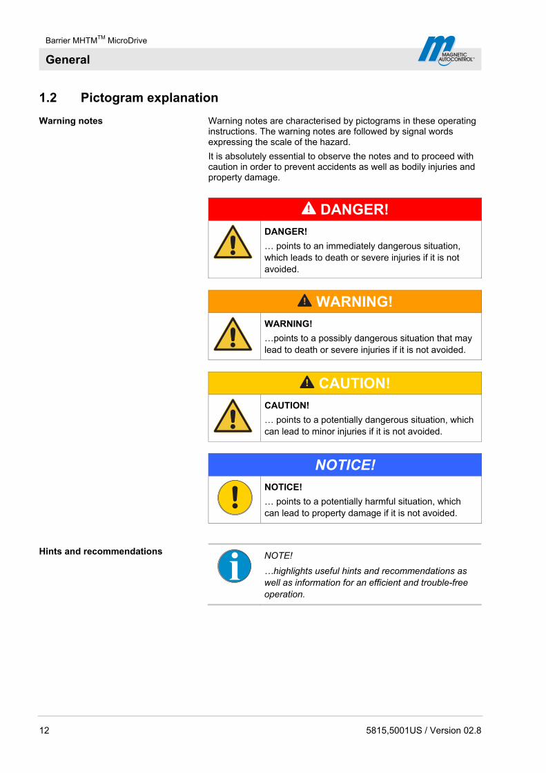
1.2 Pictogram explanation
Warning notes Warning notes are characterised by pictograms in these operating instructions. The warning notes are followed by signal words expressing the scale of the hazard.
It is absolutely essential to observe the notes and to proceed with caution in order to prevent accidents as well as bodily injuries and property damage.
DANGER!
DANGER!
… points to an immediately dangerous situation, which leads to death or severe injuries if it is not avoided.
WARNING!
WARNING!
…points to a possibly dangerous situation that may lead to death or severe injuries if it is not avoided.
CAUTION!
CAUTION!
… points to a potentially dangerous situation, which can lead to minor injuries if it is not avoided.
NOTICE!
NOTICE!
… points to a potentially harmful situation, which can lead to property damage if it is not avoided.
Hints and recommendations
NOTE!
…highlights useful hints and recommendations as well as information for an efficient and trouble-free operation.
Barrier MHTMTM MicroDrive
General
5815,5001US / Version 02.8 13
1.3 Limitation of liability
All specifications and notes in these operating instructions were compiled with consideration to the valid standards and regulations, the state of the art as well as to our long-standing knowledge and experience.
The manufacturer is not liable for damages caused by:
Non-observance of the operating instructions
Improper use
Deployment of non-trained personnel
Arbitrary modifications
Technical changes
Use of non-approved spare and wear parts.
The actual scope of supply may differ from the explanations and illustrations described in this manual in case of special designs, if additional order options are made use of, or due to latest technical changes.
Incidentally, the responsibilities agreed upon in the delivery contract, the general terms and conditions as well as the manufacturer's conditions of delivery and the statutory provisions valid at the time of contract conclusion shall apply.
In no event shall MAGNETIC be liable for any incidental, indirect, special or consequential damages in connection with the use of the product.
1.4 Copyright protection
MAGNETIC retains sole and exclusive ownership of all intellectual property rights with respect to the products.
Surrendering the operating instructions to third parties without written permission of the manufacturer is not permitted.
NOTE!
Content details, texts, drawings, pictures and other illustrations are protected by copyright and are subject to industrial property rights. Any improper use shall be liable to prosecution.
Any type and form of duplication – also of extracts – as well as the exploitation and/or communication of the contents are not per-mitted without the manufacturer's written declaration of consent.
Barrier MHTMTM MicroDrive
General
14 5815,5001US / Version 02.8
1.5 Scope of delivery
The scope of delivery comprises:
1 barrier housing incl. drive unit and control
1 Barrier
2 Mounting profiles
2 Warning signs
Edge protection
Options if applicable
Supplied documentation per barrier:
These operating instructions.
1.6 Warranty
Subject to the condition that the operating instructions are observed, and that no inadmissible operations are carried out on the technical equipment, and that the installation has suffered no mechanical damage, MAGNETIC grants a warranty on all mechanical and electrical components of the product to the extent as stated in its standard terms of sales and delivery or as contractually agreed in writing.
MAGNETIC makes no warranties, express or implied, regarding the products, including the value, design, condition, merchantability or fitness for particular purpose or use of the products.
1.7 Customer service
Your vendor is available to you for technical information
For the address, see invoice, delivery note or the reverse of these instructions.
NOTE!
In order to enable fast handling note the data of the type plate such as type, serial number, version etc. before calling.
1.8 UL-Declaration
UL-Declaration refer to page 179.
Barrier MHTMTM MicroDrive
General
5815,5001US / Version 02.8 15
1.9 Environmental protection
NOTICE!
NOTICE! Danger for the environment by improper disposal of components or the barrier!
In case of improper disposal of components or the barrier, damage to the environment may result.
Therefore:
– Observe the valid environmental directives.
– After appropriate disassembly the parts have to be recycled.
– Separate recyclable fraction and feed to recycling.

Barrier MHTMTM MicroDrive
Safety
16 5815,5001US / Version 02.8
2 Safety
2.1 Intended use of the barriers
The MAGNETIC MHTMTM MicroDrive barrier is intended for installation only on passageway used for vehicles. Pedestrians must be supplied with a separate access opening. The pedestrian access opening shall be designed to promote pedestrian usage. Locate the barrier such that persons will not come in contact with the vehicular passageway during the entire path of travel of the vehicular barrier.
The barrier is either controlled by a person in manual operating modes or by access control systems in automatic operating modes and monitored by induction loops and/or safety light barriers.
Electrical energy is used exclusively for operating the barrier. The barrier arm weight is balanced out by spring energy.
The barrier consists of the barrier housing with drive system and control, as well as the barrier arm.
2.1.1 Intended use for certain road vehicles
Certain road vehicles according to chapter 2.1 paragraph 1 need to have sufficiently large metal areas in the vehicle floor area to enable detection by induction loops.
Other or complementary safety facilities must be provided for road vehicles that cannot be detected by induction looks due to the metal area in the vehicle floor area being too small.
Barrier MHTMTM MicroDrive
Safety
5815,5001US / Version 02.8 17
2.1.2 Non-Intended use
Control of pedestrian traffic as contrary to intended use.
The barriers must not be used at railway crossings.
The barriers are not approved for pedestrian traffic, bicycles or animals.
The barriers must not be used in explosive environments.
All uses not described as intended use are prohibited.
No accessories must be connected or installed if they are not specified expressly according to quantity and characteristics and approved by Magnetic Autocontrol.
WARNING!
WARNING! Non-intended use is dangerous!
Every non-intended use can lead to dangerous situations.
Therefore:
– Only use barrier as intended.
– All specifications in these operating instructions have to be strictly complied with.
Any types of claims due to damage arising from improper use are excluded. The operator alone shall be responsible for any damage arising from improper use.

Barrier MHTMTM MicroDrive
Safety
18 5815,5001US / Version 02.8
2.2 Operator's responsibility
The operator must comply with the statutory obligations regarding work safety.
In addition to the work safety notes in these operating instructions, the safety, accident prevention and environmental provisions applicable for the area the barrier is used in must be complied with.
In particular, the operator must:
gather information on applicable work protection provisions.
determine additional dangers in a risk assessment.
implement the required method of operation of the barrier on site from the operating instructions.
regularly verify throughout the barrier's time of use that the operating instructions drawn up by him comply with the current state of the regulations.
adapt the operating instructions to any new provisions, standards and usage conditions - where required.
clearly determine the responsibilities for installation, operation, maintenance and cleaning of the barrier.
ensure that all employees that are working at or with the barrier have read and understood the operating instructions.
Furthermore, the operator must train personnel regarding the use of the barrier at regular intervals and provide information on possible danger.
Furthermore, the operator is responsible for:
keeping the barrier in perfect technical order and condition at all times.
maintaining the barrier according to the maintenance intervals and performing the safety inspections as stipulated.
checking all protective facilities for completeness and proper function at regular intervals.
The operator is also responsible that the danger area of the barrier arm cannot be accessed by any unauthorised, and in particular not by children, under any circumstances.
2.3 Changes and modifications
Changes, modifications and re-builds of the barrier or installation can cause unforeseen danger.
A written authorisation of the manufacturer is required before executing any technical changes and extensions on the barrier.
Barrier MHTMTM MicroDrive
Safety
5815,5001US / Version 02.8 19
2.4 Specialists and operating personnel
2.4.1 Requirements
WARNING!
WARNING! Risk of injury in case of inadequate qualification!
Improper handling can lead to considerable bodily injuries and property damage.
Therefore:
– Have any activities only carried out by the individuals designated for that purpose.
The operating instructions specify the following qualification requirements for the different fields of activity:
Instructed people have been instructed during instructions provided by the operator with regard to the work assigned to them and possible hazards arising from improper conduct.
Specialised staff are able, due their technical training, knowledge and experience as well as their knowledge of the pertinent regulations able to carry out the work assigned to it and to independently recognize potential hazards.
Electrical specialists are able, due to their technical training, knowledge and experiences as well as knowledge of the relevant standards and regulations, to execute tasks on electrical systems and to independently recognize possible hazards. In Germany, the electrical specialist must comply with the provisions of accident prevention regulation BGV A3 (e.g. master electrical fitter). Appropriate regulations apply in other countries. The regulations valid there must be observed. The installation is to be made by a professional installer according to NFPA 70 National Electrical Code and Local Code.
MHTMTM MicroDrive service experts comply with the requirements of the electricians named here. Additionally, these electricians are trained and authorised by MAGNETIC to perform special repair and service work on MHTMTM MicroDrive barriers.
It must be expected that only those people are deployed who carry out their work reliably. People, whose ability to respond is affected, e.g. by drugs, alcohol or medicines, must not be used. Furthermore, the age and profession-specific regulations valid at the operating location must be observed when selecting personnel.

Barrier MHTMTM MicroDrive
Safety
20 5815,5001US / Version 02.8
2.5 Personal protective equipment
It is necessary to wear personal protective equipment when dealing with the barrier so as to minimise health hazards.
Before carrying out any work, properly dress in the necessary protective equipment such as work clothes, protective gloves, safety shoes, helmet and wear during work.
2.6 Occupational safety and special dangers
The remaining risks resulting from the risk analysis are specified in the following section.
Observe the safety notes listed here and the warning notes mentioned in the other chapters of these instructions to reduce health hazards and to avoid dangerous situations.
2.6.1 Danger symbols on the MHTMTM MicroDrive barrier
The relevant dangerous areas on the barriers can be identified by the following pictograms:
Electric voltage
DANGER!
DANGER! Mortal danger by electric voltage!
... indicates life threatening situations caused by electric voltage. Non-observance of the safety instructions causes severe injuries or death. Necessary work may only be carried out by an electrical specialist.
This pictogram is fixed on the following component:
– Assembly plate in the barrier housing.
WARNING!
WARNING! Danger of crushing!
… indicates the presence of components and items moving towards each other. Non-observance of the safety instructions can lead to severe injuries.
This pictogram is fixed on the following component:
– At the access points for the lever system on the front and rear of the top assembly plate.
– At the access point for the flanged shaft on the front and rear of the top assembly plate.
Barrier MHTMTM MicroDrive
Safety
5815,5001US / Version 02.8 21
Hot surfaces
CAUTION!
CAUTION! Danger of burns!
… indicates the presence of a hot surface. Non-observance of the safety instructions can lead to minor injuries.
This pictogram is fixed on the following component:
– Motor in the barrier housing.
– Heating (optional) in the barrier housing.
2.6.2 Hazard notes and occupational safety
For your own safety and for the protection of the barrier modules, the following information must be observed and complied with:
Electric voltage
DANGER!
DANGER! Mortal danger by electric voltage!
Touching live parts can be lethal.
Damage to the insulation or to individual components can be lethal.
Therefore:
– Switch off the power supply immediately in case of damage to the insulation and arrange repair.
– Only electrical specialists may carry out work on the electrical system.
– Switch off power supply and secure against re-activation before performing any work. Test for absence of voltage!
– Never bypass or deactivate fuses.
– When replacing fuses observe the correct amperage specification.
– Keep moisture and dust away from live parts. Moisture or dust may cause a short circuit. If the electrical connection is established during precipitation, e.g. rain or snow, penetration of moisture must be prevented by suitable measures, such as a protective cover.
Barrier MHTMTM MicroDrive
Safety
22 5815,5001US / Version 02.8
Electric voltage – missing protective facilities
DANGER!
DANGER! Mortal danger by electric voltage!
The safety installations that are required according to regional and local regulations must be provided by the customer. Usually these are:
– Ground fault circuit interrupter (GFCI)
– Circuit-breaker
– Appropriate listed 2-pole main switch.
Thunderstorm, lightning, electric voltage
DANGER!
DANGER! Mortal danger from lightning and electrical voltage!
If lightning strikes the barrier, contact to the barrier components and direct proximity to the barrier includes mortal danger.
Therefore:
– Never install the barrier housing and barrier arm during thunderstorms.
– Protect yourself in buildings or vehicles.
Barrier MHTMTM MicroDrive
Safety
5815,5001US / Version 02.8 23
Improper operation
WARNING!
WARNING! Danger from improper operation of the barrier!
Improper operation of the barrier can cause severe or lethal injuries!
Therefore:
– The barrier closes automatically in certain program modes. Passing of two vehicles within a single opening process must be prevented by the construction and appropriate signs or signals.
– The barrier is intended for a single drive direction at the same time. The operator must prevent concurrent oncoming traffic by suitable measures, such as signs.
– Only additions to the barrier casing or boom that are permitted by the manufacturer may be installed.
– Keep barrier area free from objects.
– Do not use the barrier arm as a lifting device.
– Never climb over or crawl under boom.
– Never sit on the barrier housing or climb over it.
– Do not sit or have yourself lifted by the boom.
– Never open or stop the boom manually.

Barrier MHTMTM MicroDrive
Safety
24 5815,5001US / Version 02.8
Entering the danger area of the barrier
WARNING!
WARNING! Danger from entering the danger area!
The MAGNETIC MHTMTM MicroDrive barriers are intended exclusively for closing off passages for motor vehicles and trucks. For vehicles that cannot be detected by induction loops, additional safety measures must be provided. Entering the danger area can cause severe or lethal injuries.
Therefore, the operator must take the following measures:
– Observing country-specific laws and regulations.
– Presence of persons and animals must be excluded.
– Marking the danger area by prohibition signs for persons, bicyclers, etc.
– If required, set up barriers such as fences and railings.
– If required, set up separate passageway for persons and bicycles.
Closing boom
WARNING!
WARNING! Danger from closing boom!
A closing boom may cause severe or lethal injury to persons, bicycler and cabriolet drivers!
Therefore:
– Install safety installations, such as a MAGNETIC safety light barrier as surveillance device. The surveillance device must prevent the closing of the barrier in case a person or a vehicle is standing below the barrier.
– Only use barrier arms approved of by MAGNETIC.
– Assemble edge protection.
– If the edge protection was damaged it must be replaced immediately or the barrier must be taken out of operation.
Barrier MHTMTM MicroDrive
Safety
5815,5001US / Version 02.8 25
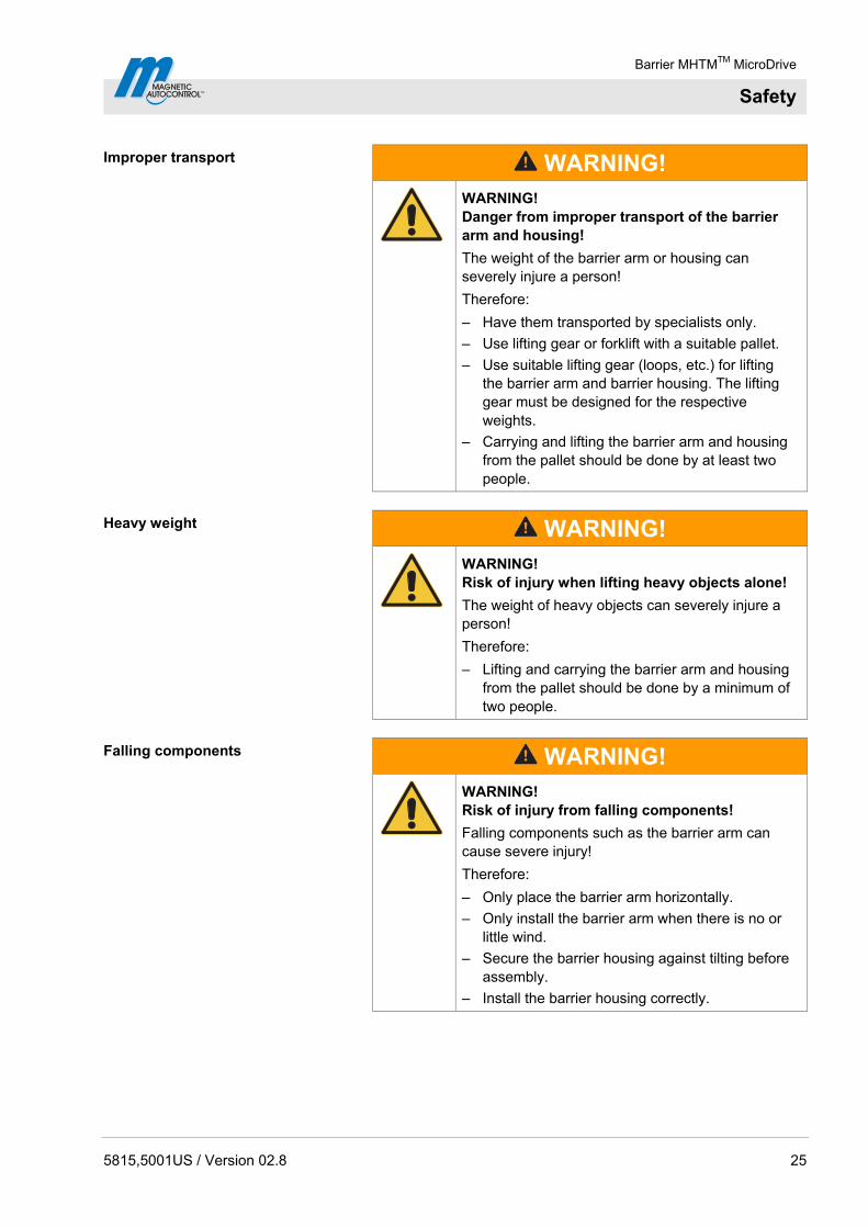
Improper transport
WARNING!
WARNING! Danger from improper transport of the barrier arm and housing!
The weight of the barrier arm or housing can severely injure a person!
Therefore:
– Have them transported by specialists only.
– Use lifting gear or forklift with a suitable pallet.
– Use suitable lifting gear (loops, etc.) for lifting the barrier arm and barrier housing. The lifting gear must be designed for the respective weights.
– Carrying and lifting the barrier arm and housing from the pallet should be done by at least two people.
Heavy weight
WARNING!
WARNING! Risk of injury when lifting heavy objects alone!
The weight of heavy objects can severely injure a person!
Therefore:
– Lifting and carrying the barrier arm and housing from the pallet should be done by a minimum of two people.
Falling components
WARNING!
WARNING! Risk of injury from falling components!
Falling components such as the barrier arm can cause severe injury!
Therefore:
– Only place the barrier arm horizontally.
– Only install the barrier arm when there is no or little wind.
– Secure the barrier housing against tilting before assembly.
– Install the barrier housing correctly.

Barrier MHTMTM MicroDrive
Safety
26 5815,5001US / Version 02.8
Insufficient fixing
WARNING!
WARNING! Risk of injury at insufficient fixing!
Insufficient fixing of individual components such as barrier housing, barrier arm and additions permitted by the manufacturer can cause severe injury!
Therefore:
– Only qualified and skilled personnel are allowed to assemble the barrier and the appropriate components.
– Check the foundation anchors fit tightly before starting the barrier.
– Check the firm fixing of all screws according to maintenance schedule.
Danger of crushing, lever system and flange shaft
WARNING!
WARNING! Danger of crushing at opened barrier housing at the lever system and flange shaft!
The lever system and the flange shaft in the barrier housing can cause serious crushing injuries!
Therefore:
– Only skilled personnel are allowed work on the barrier housing and barrier arm.
– Only work at the barrier housing when the power supply is turned off.
– Assemble barrier housing without barrier arm.
– For assembly of the barrier arm, strictly observe the descriptions in chapter 8.7.
– Wear protective gloves if necessary.
Danger of crushing, barrier arm and flange
WARNING!
WARNING! Danger of crushing between barrier arm and barrier housing!
Moving parts may cause serious crushing injuries!
Therefore:
– Only skilled personnel are allowed work on the barrier housing and barrier arm.
– Only work at the barrier housing when the power supply is turned off
Barrier MHTMTM MicroDrive
Safety
5815,5001US / Version 02.8 27
Illegible signage
CAUTION!
CAUTION! Risk of injury by illegible symbols!
Labels and signs can become dirty or unrecognisable in the course of time.
Therefore:
– Always keep safety, warning and operating notes in a well readable condition.
– Immediately renew damaged or unrecognisable signs or labels.

Barrier MHTMTM MicroDrive
Safety
28 5815,5001US / Version 02.8
2.7 Danger area
Danger of crushing and shearing, barrier arm
WARNING!
WARNING! Danger of crushing and shearing when the barrier opens or closes!
When a barrier opens or closes, the barrier arm may lead to severe crushing or injury!
Therefore:
– Keep a distance of at least 2 ft (610 mm) between the barrier arm and other objects, such as walls, masonry or houses.
– Install the barrier system only when all exposed pinch points are eliminated or guarded.
AA
A
AA
A
Mag00208
AA
A A
A: min. 2 ft (610 mm)
Fig. 1: Danger area
A Danger area of at least 2 ft (610 mm)
Barrier MHTMTM MicroDrive
Identification
5815,5001US / Version 02.8 29
3 Identification
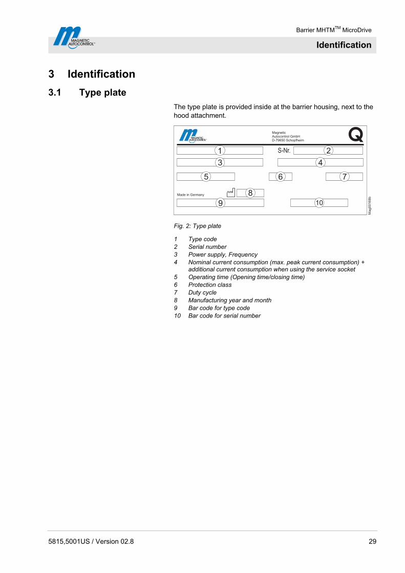
3.1 Type plate
The type plate is provided inside at the barrier housing, next to the hood attachment.
8
3 4
7
9
21
QS-Nr.
Made in Germany
10
Mag00168b
6
MagneticAutocontrol GmbHD-79650 Schopfheim
5
Fig. 2: Type plate
1 Type code 2 Serial number 3 Power supply, Frequency 4 Nominal current consumption (max. peak current consumption) +
additional current consumption when using the service socket 5 Operating time (Opening time/closing time) 6 Protection class 7 Duty cycle 8 Manufacturing year and month 9 Bar code for type code 10 Bar code for serial number
Barrier MHTMTM MicroDrive
Identification
30 5815,5001US / Version 02.8
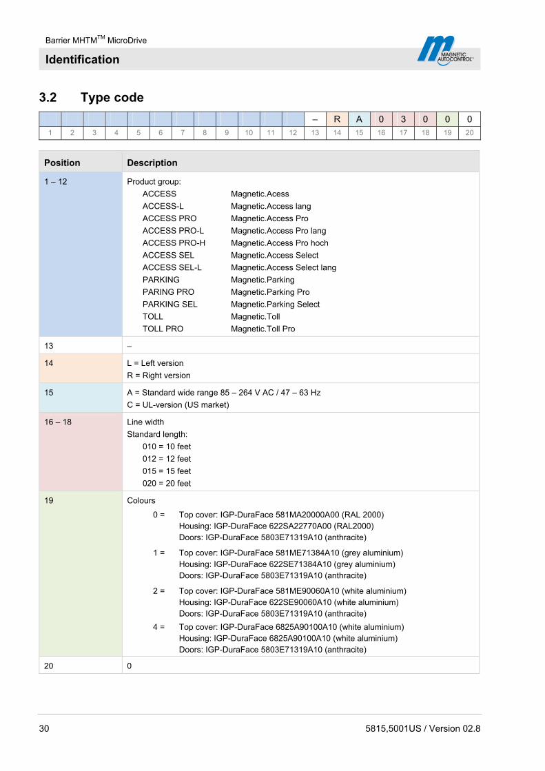
3.2 Type code
– R A 0 3 0 0 0
1 2 3 4 5 6 7 8 9 10 11 12 13 14 15 16 17 18 19 20
Position Description
1 – 12 Product group:
ACCESS Magnetic.Acess
ACCESS-L Magnetic.Access lang
ACCESS PRO Magnetic.Access Pro
ACCESS PRO-L Magnetic.Access Pro lang
ACCESS PRO-H Magnetic.Access Pro hoch
ACCESS SEL Magnetic.Access Select
ACCESS SEL-L Magnetic.Access Select lang
PARKING Magnetic.Parking
PARING PRO Magnetic.Parking Pro
PARKING SEL Magnetic.Parking Select
TOLL Magnetic.Toll
TOLL PRO Magnetic.Toll Pro
13 –
14 L = Left version
R = Right version
15 A = Standard wide range 85 – 264 V AC / 47 – 63 Hz
C = UL-version (US market)
16 – 18 Line width
Standard length:
010 = 10 feet
012 = 12 feet
015 = 15 feet
020 = 20 feet
19 Colours
0 = Top cover: IGP-DuraFace 581MA20000A00 (RAL 2000) Housing: IGP-DuraFace 622SA22770A00 (RAL2000) Doors: IGP-DuraFace 5803E71319A10 (anthracite)
1 = Top cover: IGP-DuraFace 581ME71384A10 (grey aluminium) Housing: IGP-DuraFace 622SE71384A10 (grey aluminium) Doors: IGP-DuraFace 5803E71319A10 (anthracite)
2 = Top cover: IGP-DuraFace 581ME90060A10 (white aluminium) Housing: IGP-DuraFace 622SE90060A10 (white aluminium) Doors: IGP-DuraFace 5803E71319A10 (anthracite)
4 = Top cover: IGP-DuraFace 6825A90100A10 (white aluminium) Housing: IGP-DuraFace 6825A90100A10 (white aluminium) Doors: IGP-DuraFace 5803E71319A10 (anthracite)
20 0

Barrier MHTMTM MicroDrive
Technical data
5815,5001US / Version 02.8 31
4 Technical data
4.1 Access
4.1.1 Dimensions and weight
Mag00109c
A
B
1
VarioBoom
2
1
2.17(55)
3.9
4(1
00)
min. 2 ft(min. 610) 12 ft (3660) / 14 ft (4300) / 20 ft (6000)
14.2(360)
36.4
(925)
36.0
(915)
34.5
(875)
min. 31.5 (800)
9.6
5(2
45)1
2.4
(315)
3.82 (97)
26.6
(675)
min. 2 ft(min. 610)
Fig. 3: Dimensions barrier system and barrier arm profile – "Access" series Dimensions in inch or feet are without parenthesis. Dimensions in mm are in parenthesis.
1 Object such as wall, building. etc. See also page 28, chapter 2.7. 2 VarioBoom (barrier arm) with octagon boom profile A Barrier. left version B Barrier. right version

Barrier MHTMTM MicroDrive
Technical data
32 5815,5001US / Version 02.8
Designation Unit Access Access Pro Access Select
L L L
Line width ft (m) 12 (3.66)
15 (4.57)
12 (3.66)
20 (6.10)
12 (3.66)
20 (6.10)
Barrier housing (width x depth x height)
in (mm) See page 31, Fig. 3. 12.4 x 13.6 x 36.0 (315 x 360 x 915)
Weight barrier housing lbs (kg) 88.2 (40)
Table 2: Dimensions and weight – "Access" series
4.1.2 Electrical connection
Designation Unit Access Access Pro Access Select
L L L
Supply voltage V AC 85 to 264
Frequency Hz 50 / 60
Nominal current consumption 1)
A 0.5 1.0 1.5 0.5 1.5 0.5
Max. peak current consumption 2)
A 2.5 2.5 3.5 3.0 3.5 3.0
Nominal power consumption 1)
W 25 50 95 25 95 25
Duty cycle % 100
1) The values refer to a power supply of 120 V AC / 60 Hz and without accessories.
2) The values refer to a power supply of 120 V AC / 60 Hz, with illumination, service socket not used. Using the service socket in the barrier housing increases the current consumption by 5 A.
Table 3: Electrical connection – "Access" series
4.1.3 Operating conditions
Designation Unit Access Access Pro Access Select
L L L
Ambient temperature range
°F (°C) –22 to +122 (–30 to +50)
Wind force Bft (Beaufort)
max. 10
Protection class barrier housing
─ IP 54
Table 4: Operating conditions – "Access" series
Barrier MHTMTM MicroDrive
Technical data
5815,5001US / Version 02.8 33
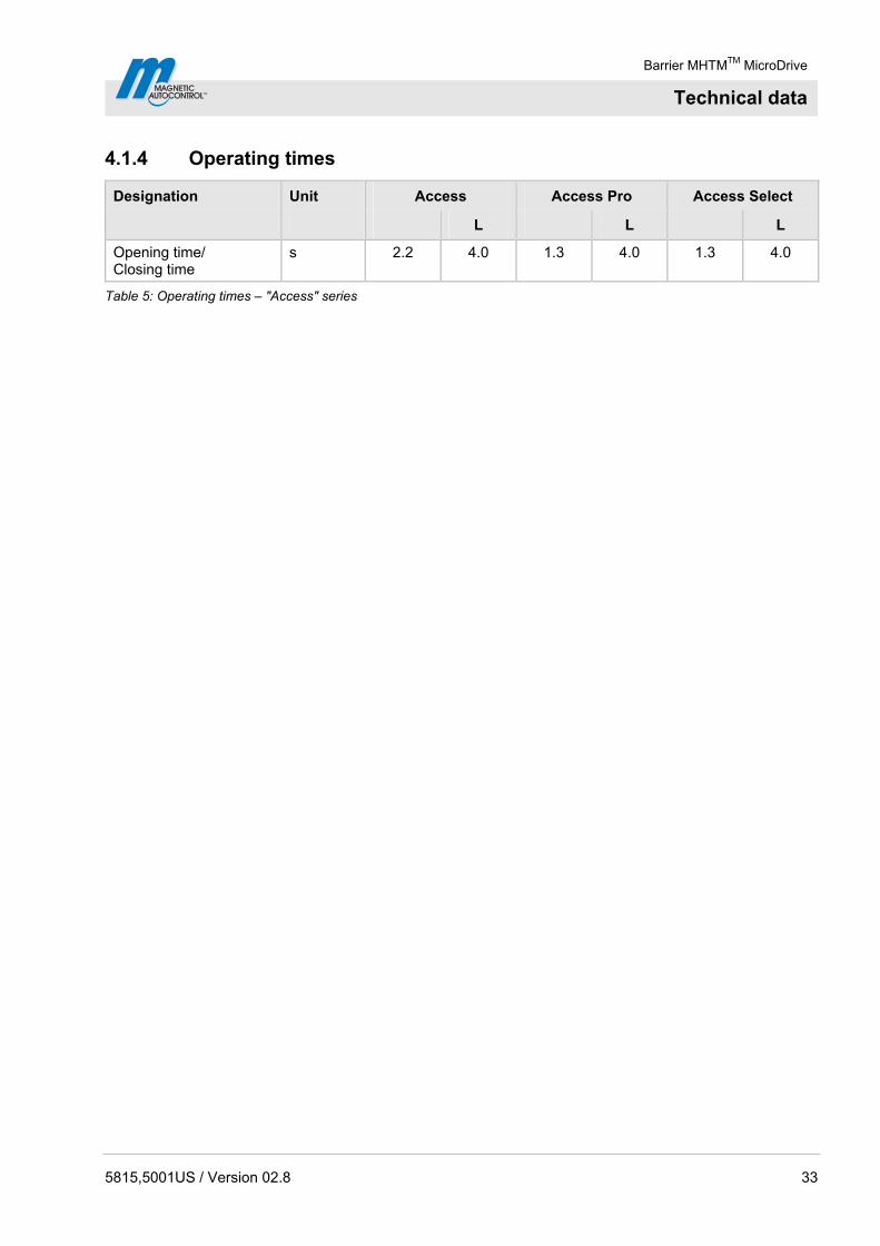
4.1.4 Operating times
Designation Unit Access Access Pro Access Select
L L L
Opening time/ Closing time
s 2.2 4.0 1.3 4.0 1.3 4.0
Table 5: Operating times – "Access" series

Barrier MHTMTM MicroDrive
Technical data
34 5815,5001US / Version 02.8
4.2 Access Pro H
4.2.1 Dimensions and weight
Mag00202a
A
B
MicroBoom
2
11
43
.90
(111
5)
min. 2 ft(min. 610)
min. 2 ft(min. 610)
36
.4(9
25
)
34
.5(8
75
)
12 ft (3660) / 14 ft (4300) / 20 ft (6000)
min. 31.5 (800)
14.2(360)
12
.4(3
15
)
3.82 (97)
9.6
5(2
45
)
2.17(55)
3.9
4(1
00
)
Fig. 4: Dimensions barrier system and barrier arm profile – "Access Pro H" series Dimensions in inch or feet are without parenthesis. Dimensions in mm are in parenthesis.
1 Object such as wall, building, etc. 2 MicroBoom (barrier arm) with octagon boom profile A Barrier, left version B Barrier, right version

Barrier MHTMTM MicroDrive
Technical data
5815,5001US / Version 02.8 35
Designation Unit Access Pro H
ft (m) 12 (3.66) 15 (4.57) 20 (6.00)
Line width ft (m) 12 (3.66)
15 (4.57)
20 (6.00)
Barrier housing (width x depth x height)
in (mm) See page 34, Fig. 4. 12.4 x 13.6 x 36.0 (315 x 360 x 915)
Weight barrier housing lbs (kg) 97 (44)
Table 6: Dimensions and weight – "Access Pro H" series
4.2.2 Electrical connection
Designation Unit Access Pro H
ft (m) 12 (3.66) 15 (4.57) 20 (6.00)
Supply voltage V AC 85 to 264
Frequency Hz 50 / 60
Nominal current consumption 1)
A 0.5 0.5 0.5
Max. peak current consumption 2)
A 3.0 3.0 3.0
Nominal power consumption 1)
W 25 25 25
Duty cycle % 100
1) The values refer to a power supply of 120 V AC / 60 Hz and without accessories.
2) The values refer to a power supply of 120 V AC / 60 Hz, with illumination, service socket not used. Using the service socket in the barrier housing increases the current consumption by 5 A.
Table 7: Electrical connection – "Access Pro H" series
4.2.3 Operating conditions
Designation Unit Access Pro H
ft (m) 12 (3.66) 15 (4.57) 20 (6.00)
Ambient temperature range
°F (°C) –22 to +122 (–30 to +50)
Wind force Bft (Beaufort)
maximal 10
Protection class barrier housing
─ IP 54
Table 8: Operating conditions – "Access Pro H"
Barrier MHTMTM MicroDrive
Technical data
36 5815,5001US / Version 02.8
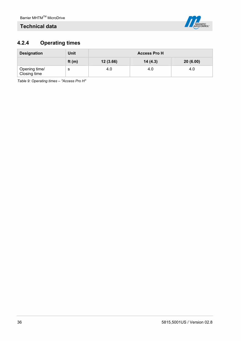
4.2.4 Operating times
Designation Unit Access Pro H
ft (m) 12 (3.66) 14 (4.3) 20 (6.00)
Opening time/ Closing time
s 4.0 4.0 4.0
Table 9: Operating times – "Access Pro H"
Barrier MHTMTM MicroDrive
Technical data
5815,5001US / Version 02.8 37
4.3 Parking
4.3.1 Dimensions and weight
Ma
g0
01
98
a
A
B
1
VarioBoom
2
1
2.17(55)
3.9
4(1
00
)
min. 2 ft(min. 610) 12 ft (3660)
14.2(360)
36
.4(9
25
)
36
.0(9
15
)
34
.5(8
75
)
min. 31.5 (800)
9.6
5(2
45
)12
.4(3
15
)
3.82 (97)
26
.6(6
75
)
min. 2 ft(min. 610)
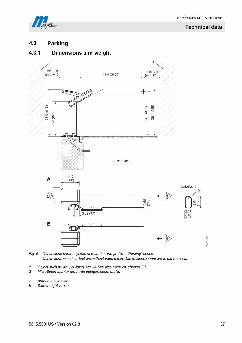
Fig. 5: Dimensions barrier system and barrier arm profile – "Parking" series Dimensions in inch or feet are without parenthesis. Dimensions in mm are in parenthesis.
1 Object such as wall, building. etc. See also page 28, chapter 2.7. 2 MicroBoom (barrier arm) with octagon boom profile A Barrier. left version B Barrier. right version

Barrier MHTMTM MicroDrive
Technical data
38 5815,5001US / Version 02.8
Designation Unit Parking Parking Pro Parking Select
Line width ft (m) 12 (3.66)
12 (3.66)
12 (3.66)
Barrier housing (width x depth x height)
in (mm) See page 37, Fig. 5. 12.4 x 13.6 x 36.0 (315 x 360 x 915)
Weight barrier housing lbs (kg) 88.2 (40)
Table 10: Dimensions and weight – "Parking" series
4.3.2 Electrical connection
Designation Unit Parking Parking Pro Parking Select
Supply voltage V AC 85 to 264
Frequency Hz 50 / 60
Nominal Current consumption 1)
A 1.0 1.5 1.5
Max. peak current consumption 2)
A 4.0 5.0 5.0
Nominal power consumption 1)
W 35 95 95
Duty cycle % 100
1) The values refer to a power supply of 120 V AC / 60 Hz and without accessories.
2) The values refer to a power supply of 120 V AC / 60 Hz, with illumination, service socket not used. Using the service socket in the barrier housing increases the current consumption by 5 A.
Table 11: Electrical connection – "Parking" series
4.3.3 Operating conditions
Designation Unit Parking Parking Pro Parking Select
Ambient temperature range
°F (°C) –22 to +122 (–30 to +50)
Wind force Bft (Beaufort)
max. 10
Protection class barrier housing
─ IP 54
Table 12: Operating conditions – Series "Parking"
4.3.4 Operating times
Designation Unit Parking Parking Pro Parking Select
Opening time/ Closing time
s 1.8 1.3 1.3
Table 13: Operating times – "Parking" series
Barrier MHTMTM MicroDrive
Technical data
5815,5001US / Version 02.8 39
4.4 Toll
4.4.1 Dimensions and weight
MicroBoom-T
Ma
g0
01
08
b
2
1
A
B
1
10 ft (3000)
min. 31.5 (800)
2.95(75)
min. 2 ft(min. 610)
8.8
6(2
55
)3
6.4
(91
0)
43
.9(1
11
5)
34
.4(8
75
)
3.82 (97)
min. 2 ft(min. 610)
14.2(360)
12
.4(3
15
)
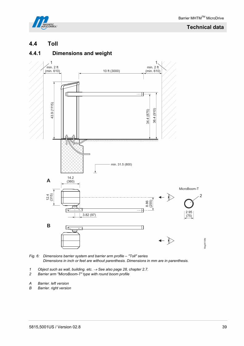
Fig. 6: Dimensions barrier system and barrier arm profile – "Toll" series Dimensions in inch or feet are without parenthesis. Dimensions in mm are in parenthesis.
1 Object such as wall, building. etc. See also page 28, chapter 2.7. 2 Barrier arm "MicroBoom-T" type with round boom profile A Barrier. left version B Barrier. right version
Barrier MHTMTM MicroDrive
Technical data
40 5815,5001US / Version 02.8
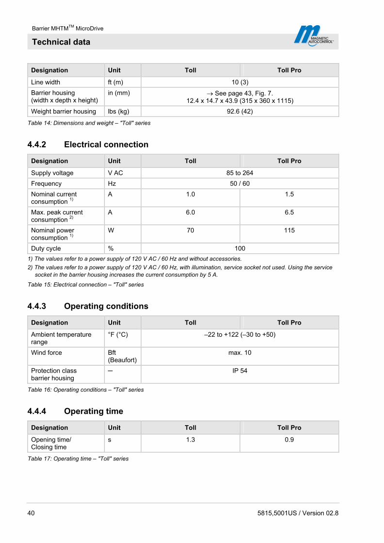
Designation Unit Toll Toll Pro
Line width ft (m) 10 (3)
Barrier housing (width x depth x height)
in (mm) See page 43, Fig. 7. 12.4 x 14.7 x 43.9 (315 x 360 x 1115)
Weight barrier housing lbs (kg) 92.6 (42)
Table 14: Dimensions and weight – "Toll" series
4.4.2 Electrical connection
Designation Unit Toll Toll Pro
Supply voltage V AC 85 to 264
Frequency Hz 50 / 60
Nominal current consumption 1)
A 1.0 1.5
Max. peak current consumption 2)
A 6.0 6.5
Nominal power consumption 1)
W 70 115
Duty cycle % 100
1) The values refer to a power supply of 120 V AC / 60 Hz and without accessories.
2) The values refer to a power supply of 120 V AC / 60 Hz, with illumination, service socket not used. Using the service socket in the barrier housing increases the current consumption by 5 A.
Table 15: Electrical connection – "Toll" series
4.4.3 Operating conditions
Designation Unit Toll Toll Pro
Ambient temperature range
°F (°C) –22 to +122 (–30 to +50)
Wind force Bft (Beaufort)
max. 10
Protection class barrier housing
─ IP 54
Table 16: Operating conditions – "Toll" series
4.4.4 Operating time
Designation Unit Toll Toll Pro
Opening time/ Closing time
s 1.3 0.9
Table 17: Operating time – "Toll" series

Barrier MHTMTM MicroDrive
Technical data
5815,5001US / Version 02.8 41
4.5 Control unit
Designation Unit MGC (MAGNETIC Gate Controller)
Supply voltage V DC 24
Current consumption ─ max. 1 A, max. 300 mA + current
consumption of the different plug-in modules
Power consumption ─ max 24 W, Max. 7.2 W + power consumption
of the different plug-in modules
Control device safety ─ 1 A T
Output voltage V DC 24 Output clamp X2
Max. output current mA 300
Number ─ 8
Input voltage V DC 24 ± 10 %
Input current ─ < 10 mA per input
Digital inputs
Max. line length without overvoltage module 1)
ft (m) 100 (30)
Number ─ 4 (open collector)
Switching voltage V DC 24 ± 10 %
Max. switching current mA 100
Digital outputs
Max. line length without overvoltage module 1)
ft (m) 100 (30)
Number ─ 3 normally-open contact and 3 change-over contacts, isolated
Max. switching voltage V AC / DC 30
Switching current mA 10 mA to 1 A
Output relay
Max. line length without overvoltage module 1)
ft (m) 100 (30)
Display ─ Graphics display, 128 x 65 Pixel
Language display ─ Selectable: German, English, French, Spanish, Italian or
Portuguese
Number of slots for plug-in modules ─ 5
1) For line lengths exceeding 30 m, overvoltage modules must be installed in front of the terminal clamps.
Table 18: Control unit
Barrier MHTMTM MicroDrive
Technical data
42 5815,5001US / Version 02.8
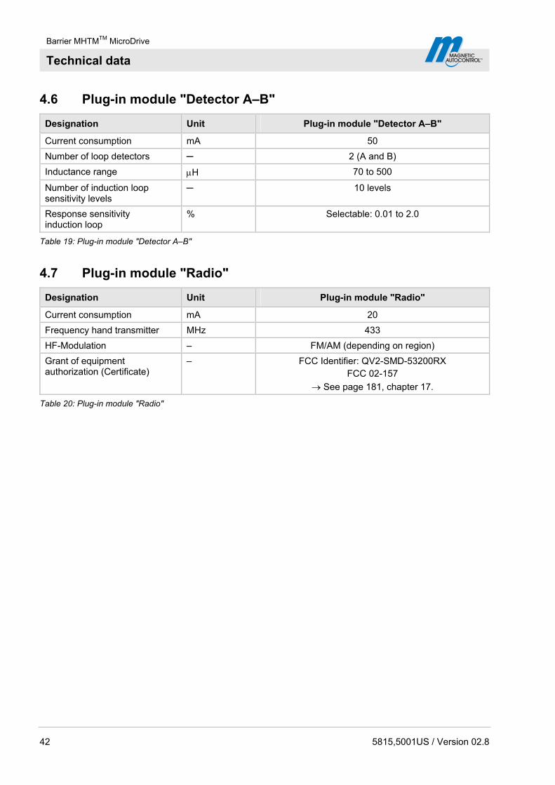
4.6 Plug-in module "Detector A–B"
Designation Unit Plug-in module "Detector A–B"
Current consumption mA 50
Number of loop detectors ─ 2 (A and B)
Inductance range H 70 to 500
Number of induction loop sensitivity levels
─ 10 levels
Response sensitivity induction loop
% Selectable: 0.01 to 2.0
Table 19: Plug-in module "Detector A–B"
4.7 Plug-in module "Radio"
Designation Unit Plug-in module "Radio"
Current consumption mA 20
Frequency hand transmitter MHz 433
HF-Modulation – FM/AM (depending on region)
Grant of equipment authorization (Certificate)
– FCC Identifier: QV2-SMD-53200RX FCC 02-157
See page 181, chapter 17.
Table 20: Plug-in module "Radio"

Barrier MHTMTM MicroDrive
Design and function
5815,5001US / Version 02.8 43
5 Design and function
5.1 Design
5.1.1 Access and Parking
Ma
g0
01
99
21
4
5
3
Fig. 7: Barrier system design series "Access" and Series "Parking"
1 Barrier housing 2 VarioBoom (barrier arm) 3 Pendulum support from 15 ft (4.57 m) barrier arm length 4 Empty conduits for mains cable, control lines and induction loop 5 Concrete foundation with reinforcement
Barrier MHTMTM MicroDrive
Design and function
44 5815,5001US / Version 02.8
5.1.2 Access Pro H
Mag00203
2
1
4
5
3
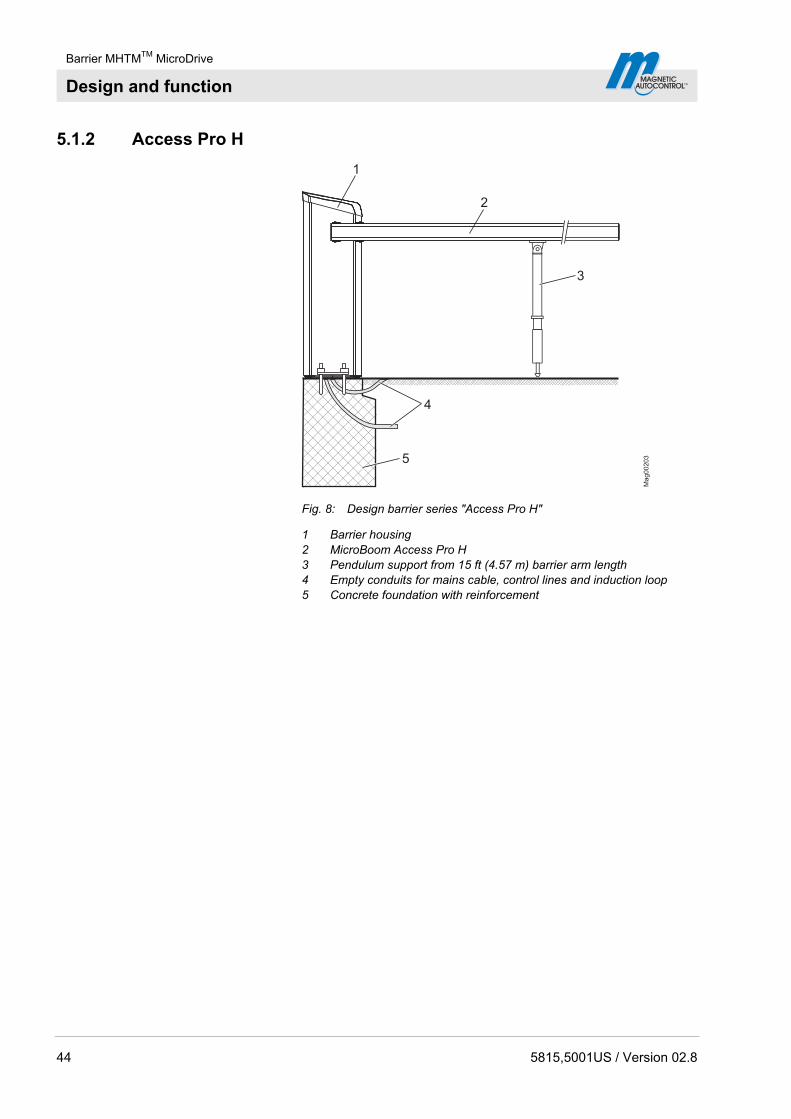
Fig. 8: Design barrier series "Access Pro H"
1 Barrier housing 2 MicroBoom Access Pro H 3 Pendulum support from 15 ft (4.57 m) barrier arm length 4 Empty conduits for mains cable, control lines and induction loop 5 Concrete foundation with reinforcement
Barrier MHTMTM MicroDrive
Design and function
5815,5001US / Version 02.8 45
5.1.3 Toll
Ma
g0
02
00
2
3
4
1
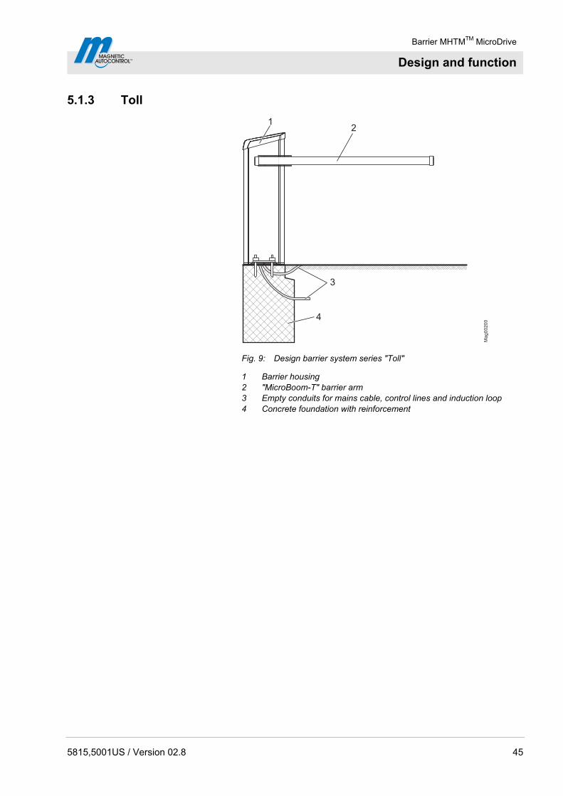
Fig. 9: Design barrier system series "Toll"
1 Barrier housing 2 "MicroBoom-T" barrier arm 3 Empty conduits for mains cable, control lines and induction loop 4 Concrete foundation with reinforcement
Barrier MHTMTM MicroDrive
Design and function
46 5815,5001US / Version 02.8
5.2 Function
The barrier consists of a barrier housing with drive system and a barrier arm.
The drive system consists of an electric motor, control unit, and the lever system. The lever system locks the barrier arm in both end positions. In case of power outage, the barrier arm can easily be moved by hand. Integrated balancing springs in the lever system balance out the boom weight exactly. These balancing springs are pre-set in the factory.
Sensors integrated in the motor supply exact data on every correct position of the barrier arm and thus serve the control unit to control the best acceleration and deceleration.
For the series "Access" and "Parking", the angled barrier arm "VarioBoom" is used, this barrier arm enables driving through even at an opening of only 35°.
For the "Toll" series, the barrier arm is designed as a "Swing Away". That means, if a vehicle drives against the boom, it will snap from its flange. Depending on version, the barrier arm will automatically or by hand be returned to its original position.
Safety facilities like induction loops or safety light barriers must be installed on site in all cases. The safety installations must ensure that the barrier closes only after the vehicle has passed through. Safety installations, such as induction loops can be purchased from MAGNETIC. The safety light barriers must be MAGNETIC ones.
Barrier MHTMTM MicroDrive
Transport and storage
5815,5001US / Version 02.8 47
6 Transport and storage
6.1 Safety
Improper transport
WARNING!
WARNING! Danger from improper transport of the barrier arm and housing!
The weight of the barrier arm or housing can severely injure a person!
Therefore:
– Have them transported by specialists only.
– Use lifting gear or forklift with a suitable pallet.
– Use suitable lifting gear (loops, etc.) for lifting the barrier arm and barrier housing. The lifting gear must be designed for the respective weights.
– Lifting and carrying the barrier arm and housing from the pallet should be done by a minimum of two people.
Heavy weight
WARNING!
WARNING! Risk of injury when lifting heavy objects alone!
The weight of heavy objects can severely injure a person!
Therefore:
– Lifting and carrying the barrier arm and housing from the pallet should be done by a minimum of two people.
Barrier MHTMTM MicroDrive
Transport and storage
48 5815,5001US / Version 02.8
Improper transport
NOTICE!
NOTICE!
The barrier system can be damaged by improper transport!
Substantial material damages can result from improper transport.
Therefore:
– Have all transport work performed by trained personnel.
– When unloading the packages and during in-house transportation always proceed with greatest care and caution.
– Observe the symbols on the packaging.
– Observe the dimensions of the barrier system.
– Loading, unloading as well as moving the barrier system must take place with greatest care.
– Only remove packaging directly before assembly.
Personal protective equipment The following must be worn during all transport work:
Work clothes
Protective gloves
Safety shoes
Protective helmet.
6.2 Transport inspection
Immediately check the delivery after receipt for completeness and transport damages.
Proceed as follows in the case of outwardly recognisable transport damage:
Do not accept the delivery or only under reserve.
Note the extent of damage on the transport documents or on the delivery note of the forwarder.
Lodge complaint.
NOTE!
Lodge a complaint for each defect, as soon as it is recognized. Compensation claims can only be submitted within the valid complaint periods.
Barrier MHTMTM MicroDrive
Transport and storage
5815,5001US / Version 02.8 49
6.3 Transport
Barrier housing and barrier arm are delivered separately.
The lifting gear must be designed for the weight of the barrier housing and barrier arm.
For transport barrier modules refer to the safety notes on page 47, chapter 6.1.
For future transports:
Secure loose cables.
Secure against vibrations.
Securely fasten the barrier housing and barrier arm prior to transport (e.g. screw it onto a pallet).
Transport and put down barrier housing and barrier arm with a forklift and lift with suitable lifting gear.
6.4 Storage
Store the barrier or packages under the following conditions:
Do not store outdoors.
Store dry and dust free.
Do not expose to aggressive media.
Protect against solar irradiation.
Avoid mechanical vibrations.
Storage temperature: –22 to +158 °F (–30 to +70 °C)
Relative humidity: max. 95 %, non-condensing
Check the general condition of all components and packaging regularly, if they are stored for longer periods than 3 months.

Barrier MHTMTM MicroDrive
Design notes for induction loops
50 5815,5001US / Version 02.8
7 Design notes for induction loops
For assembly and inspection, see page 61, chapter 8.4.
Please observe following points when dimensioning the induction loops:
Induction loops respond only to metal. The mass is thereby not important, but the size of the loop's surface, which will be covered by the metal part is.
The induction loops must not respond to persons or objects with a small metal portion like a bicycle for instance.
Safety loops must secure the danger area underneath the barrier arm throughout the entire length.
Opening loops must be installed right in front of the safety loop. The maximum distance between safety loop and opening loop must be not greater than max. 3.28 ft (1.0 m).
Arrangement passenger car loops – standard
Ma
g0
00
73
1
2 3
4
3.28 ft(1.00 m)
max.3.28 ft
(1.00 m)3.28 ft
(1.00 m)
6.56 ft(2.00 m)
ca. 0.98 ft(0.30 m)
Fig. 10: Passenger car loop
1 Maximum distance between opening loop and safety loop 2 Safety loop 3 Opening loop 4 Barrier

Barrier MHTMTM MicroDrive
Design notes for induction loops
5815,5001US / Version 02.8 51
Arrangement passenger car loops – passage with long opening loop
Mag00074
1 2
3
Fig. 11: Passenger car loops – passage with long opening time
1 Safety loop 2 Opening loop 3 Barrier
Due to a long opening loop vehicles can drive through without needing to stop.
Arrangement of truck loops
1 2
3 Ma
g0
00
75
8.20 ft – 13.1 ft(2.50 m – 4.00 m)
3.28 ft(1.00 m)
ca. 0.98 ft(0.,30 m)
max. 13.1 ft(4.00 m)
3.28 ft(1.00 m)
Fig. 12: Lorry loops
1 Safety loop 2 Opening loop 3 Barrier
For truck passages the safety loop in the direction of travel must be at least 8.2 ft (2.5 m) long.
Barrier MHTMTM MicroDrive
Design notes for induction loops
52 5815,5001US / Version 02.8
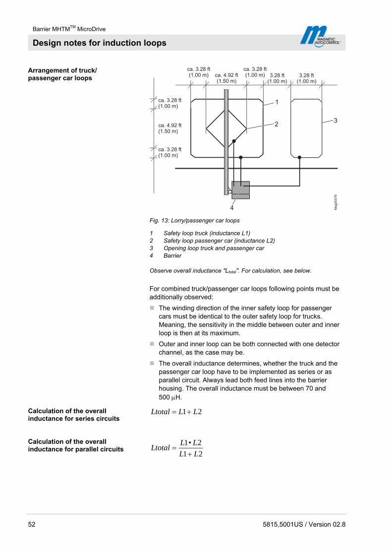
Arrangement of truck/ passenger car loops
Ma
g0
00
76
23
4
1
ca. 3.28 ft(1.00 m) ca. 4.92 ft
(1.50 m)
ca. 3.28 ft(1.00 m) 3.28 ft
(1.00 m)
ca. 3.28 ft(1.00 m)
ca. 4.92 ft(1.50 m)
ca. 3.28 ft(1.00 m)
3.28 ft(1.00 m)
Fig. 13: Lorry/passenger car loops
1 Safety loop truck (inductance L1) 2 Safety loop passenger car (inductance L2) 3 Opening loop truck and passenger car 4 Barrier Observe overall inductance "Ltotal". For calculation, see below.
For combined truck/passenger car loops following points must be additionally observed:
The winding direction of the inner safety loop for passenger cars must be identical to the outer safety loop for trucks. Meaning, the sensitivity in the middle between outer and inner loop is then at its maximum.
Outer and inner loop can be both connected with one detector channel, as the case may be.
The overall inductance determines, whether the truck and the passenger car loop have to be implemented as series or as parallel circuit. Always lead both feed lines into the barrier housing. The overall inductance must be between 70 and 500 H.
Calculation of the overall inductance for series circuits
21 LLLtotal
Calculation of the overall inductance for parallel circuits
21
2•1
LL
LLLtotal
Barrier MHTMTM MicroDrive
Assembly and installation
5815,5001US / Version 02.8 53
8 Assembly and installation
8.1 Safety
See also safety notes on page 20, chapter 2.6 "Occupational safety and special dangers".
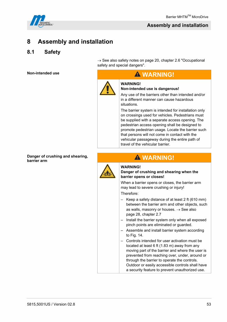
Non-intended use
WARNING!
WARNING! Non-intended use is dangerous!
Any use of the barriers other than intended and/or in a different manner can cause hazardous situations.
The barrier system is intended for installation only on crossings used for vehicles. Pedestrians must be supplied with a separate access opening. The pedestrian access opening shall be designed to promote pedestrian usage. Locate the barrier such that persons will not come in contact with the vehicular passageway during the entire path of travel of the vehicular barrier.
Danger of crushing and shearing, barrier arm
WARNING!
WARNING! Danger of crushing and shearing when the barrier opens or closes!
When a barrier opens or closes, the barrier arm may lead to severe crushing or injury!
Therefore:
– Keep a safety distance of at least 2 ft (610 mm) between the barrier arm and other objects, such as walls, masonry or houses. See also page 28, chapter 2.7
– Install the barrier system only when all exposed pinch points are eliminated or guarded.
– Assemble and install barrier system according to Fig. 14.
– Controls intended for user activation must be located at least 6 ft (1.83 m) away from any moving part of the barrier and where the user is prevented from reaching over, under, around or through the barrier to operate the controls. Outdoor or easily accessible controls shall have a security feature to prevent unauthorized use.
Barrier MHTMTM MicroDrive
Assembly and installation
54 5815,5001US / Version 02.8
General
WARNING!
WARNING! Danger by inappropriate installation!
Inappropriate installation can cause severe injuries!
Therefore:
– Only specialist personnel or electrical specialists must perform any assembly and installation tasks.
– Prior to work, ensure that there is sufficient assembly space.
– Pay attention to tidiness and cleanness at the assembly site! Loosely stacked or lying around components and tools are accident sources.
– Comply with specifications for foundations and reinforcement.
– Ensure correct arrangement and fit on all assemblies and components.
– Install the indicated fastening elements correctly.
Personal protective equipment The following must be worn during all assembly and installation work:
Work clothes
Protective gloves
Safety shoes
Protective helmet.
Barrier MHTMTM MicroDrive
Assembly and installation
5815,5001US / Version 02.8 55
8.2 Required steps
The following steps are to be completed prior to assembly and installation:
Laying the foundation with reinforcement for the barrier and install empty conduits.
Set up foundation for light barrier post and empty conduits.
Installing induction loops.
The following procedures have to be observed during assembly and installation:
Unpack barrier and accessories. Mount barrier housing on the foundation. Mount light barrier post on the foundation. Mount safety light barrier. Assemble barrier arm (VarioBoom only). Mount edge protection. Mount barrier arm. Adjust balancing springs. Align barrier housing and light barrier post. Assemble and install signalling device.
Arrange electrical connections. See page 91, chapter 9.
Barrier MHTMTM MicroDrive
Assembly and installation
56 5815,5001US / Version 02.8
8.3 Foundation and empty conduits
Ma
g0
02
27
1
2
4
3
1
5
6
11.81 (300)
min. 2 ft(min. 610)
min
.31.5
(800)
3.9
4(1
00
)
23.6 (600)
min. 2 ft(min. 610)
min
.31.5
(800)
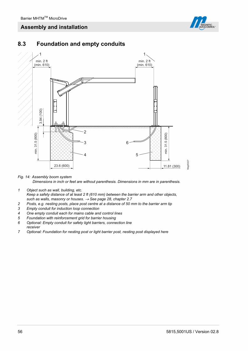
Fig. 14: Assembly boom system Dimensions in inch or feet are without parenthesis. Dimensions in mm are in parenthesis.
1 Object such as wall, building, etc. Keep a safety distance of at least 2 ft (610 mm) between the barrier arm and other objects, such as walls, masonry or houses. See page 28, chapter 2.7
2 Posts, e.g. nesting posts, place post centre at a distance of 50 mm to the barrier arm tip 3 Empty conduit for induction loop connection 4 One empty conduit each for mains cable and control lines 5 Foundation with reinforcement grid for barrier housing 6 Optional: Empty conduit for safety light barriers, connection line
receiver 7 Optional: Foundation for nesting post or light barrier post, nesting post displayed here

Barrier MHTMTM MicroDrive
Assembly and installation
5815,5001US / Version 02.8 57
8.3.1 Foundation and empty conduits for the barrier
Assembly site The assembly site must meet the following requirements:
The barrier must be visible from the operating person.
The barrier must not be put up where there is a danger of flooding.
Keep a safety distance of at least 2 ft (610 mm) between the barrier arm and objects such as walls, buildings, etc. See page 28, chapter 2.7 and page 56, Fig. 14
Foundation and reinforcement The foundation must meet the following requirements: See page 56, Fig. 14 and page 58, Fig. 15.
Have sufficient load-carrying capacity. (concrete foundations: C35/45 XD3 XF2)
Water cement value: 0.5
Foundation depth: at least 31.5 in (800 mm), frost-protected foundation depth to be adjusted to the local situation.
Foundation section: 17.7 in x 23.6 in (450 mm x 600 mm)
Reinforcing mesh as shown in figure Fig. 16.
Surface has to be non-combustible material.
Empty conduits The empty conduits must meet the following requirements: See page 56, Fig. 15.
Separate empty conduits for mains cable and control line Diameter: 1.14 ft (29 mm) each
Optional empty conduit for induction loop. Diameter: 1.14 (29 mm) each
Conduits have to be planned to a sufficient length.
NOTE!
To provide a trouble-free operation use separate conduits for control lines and mains cables.

Barrier MHTMTM MicroDrive
Assembly and installation
58 5815,5001US / Version 02.8
Laying the foundation, Installing empty conduits
AA
1
2
345
Mag001556
7
(135)5.31
(135)5.31
(160)
6.307.09
6.30
(160)
23.6 (600)
17.7(450) 19.7 (500)
(180)(180)7.09
min
.31.5
(800)
Fig. 15: Foundation plan Dimensions in inch or feet are without parenthesis. Dimensions in mm are in parenthesis.
1 Foundation anchor (4 pcs.) 2 Optional when using loop connection;
empty conduit for loop connection, diameter: 1.14 in (29 mm) 3 Empty conduit for induction loop, diameter: 1.14 in (29 mm) 4 Empty conduit for control lines, diameter: 1.14 (29 mm) 5 Concrete foundations (C35/45 XD3 XF2) 6 Roadway 7 Foundation depth: at least 31.5 in (800 mm), frost-protected
foundation depth to be adjusted to the local situation.
1. Dig foundation hole pursuant to Fig. 14 and Fig. 15.
Ma
g0
01
56
6.50
(165)
6.50
(165)
(3 x 12�
(5 x 8� 450 x 390)
640 x 410)
5 x 0.31� 17.7 x 16.6
3 x 0.47� 25.2 x 16.1
Fig. 16: Reinforcement grid Dimensions in inch or feet are without parenthesis. Dimensions in mm are in parenthesis.
2. Place reinforcement grid pursuant to Fig. 16 in the foundation hole.

Barrier MHTMTM MicroDrive
Assembly and installation
5815,5001US / Version 02.8 59
3. Place empty conduits pursuant to Fig. 15 in the foundation hole.
4. Close empty conduits to prevent water from entering.
5. Fill concrete foundation pursuant to Fig. 14.
6. Create flat line in the base area. The following requirements must be fulfilled:
Level and horizontal.
Surface deviation: max. 1 in/ft2 (1 mm/m2)
7. Let concrete cure.
8. Apply moisture protection agent to concrete surface.
NOTE!
We recommend applying moisture protection either in the form of sealing sludges such as 1100 Hansit or ready-made solution such as Sikagard® 703 W or deepdry® to the concrete surface before housing assembly. Moisture protection prevents entering of moisture into the housing from the concrete floor.
8.3.2 Foundation and empty conduits for light barrier post
Assembly site The nesting post and light barrier post must not be put up where there is a danger of flooding.
Foundation The foundation must meet the following requirements: See page 56, Fig. 14 and page 60, Fig. 17.
Have sufficient load-carrying capacity. (concrete foundations: C35/45 XD3 XF2)
Water cement value: 0.5
Foundation depth: at least 31.5 in (800 mm), frost-protected foundation depth to be adjusted to the local situation.
Foundation section: 11.81 x 11.81 in (300 mm x 300 mm)
Empty conduit If the barrier system is equipped with a light barrier, an empty conduit must be installed for the transmitter connection line. Conduits have to be planned to a sufficient length.
Barrier MHTMTM MicroDrive
Assembly and installation
60 5815,5001US / Version 02.8
Laying the foundation, installing empty conduits
1
3
Mag00223
2
11.81 (300) 11.81 (300)x
x
x xx
x
4
min
.31.5
(800)
3.1
5(8
0)
4.3
3(1
10)
x = 3.94 (100)
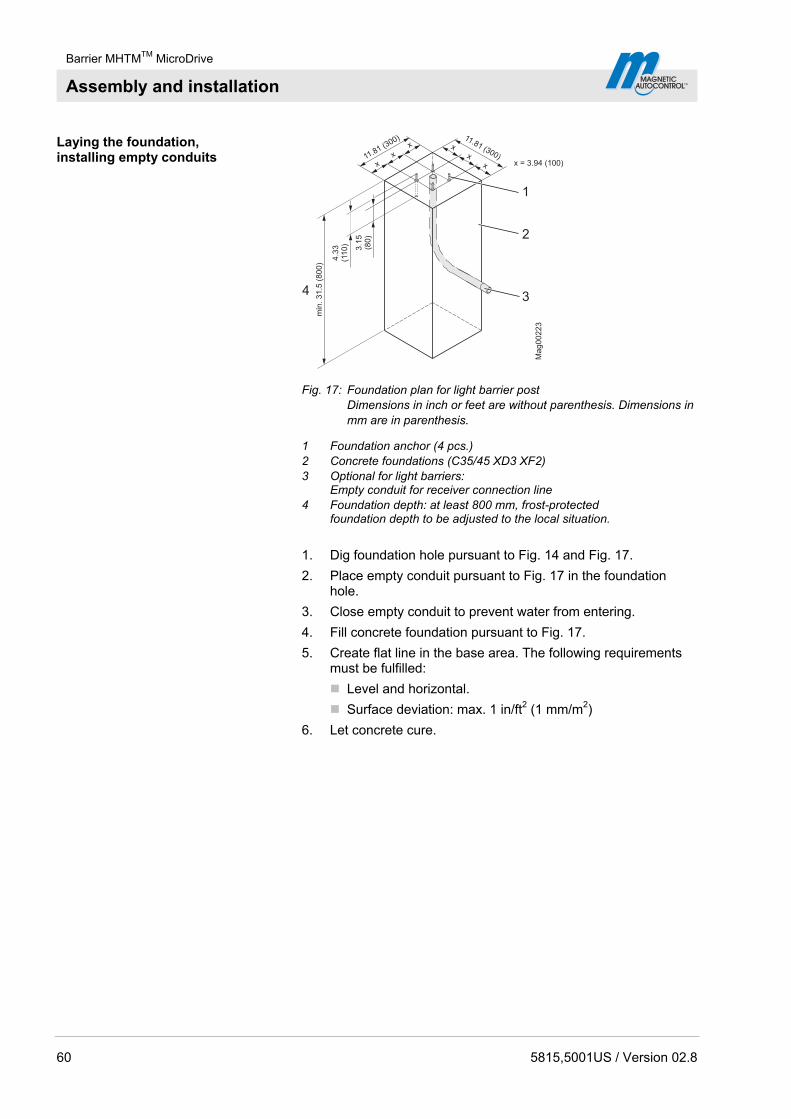
Fig. 17: Foundation plan for light barrier post Dimensions in inch or feet are without parenthesis. Dimensions in mm are in parenthesis.
1 Foundation anchor (4 pcs.) 2 Concrete foundations (C35/45 XD3 XF2) 3 Optional for light barriers:
Empty conduit for receiver connection line 4 Foundation depth: at least 800 mm, frost-protected
foundation depth to be adjusted to the local situation.
1. Dig foundation hole pursuant to Fig. 14 and Fig. 17.
2. Place empty conduit pursuant to Fig. 17 in the foundation hole.
3. Close empty conduit to prevent water from entering.
4. Fill concrete foundation pursuant to Fig. 17.
5. Create flat line in the base area. The following requirements must be fulfilled:
Level and horizontal.
Surface deviation: max. 1 in/ft2 (1 mm/m2)
6. Let concrete cure.
Barrier MHTMTM MicroDrive
Assembly and installation
5815,5001US / Version 02.8 61
8.4 Assembly and installation of induction loops
Depending on the application safety installations must be installed on site. Induction loops, light barriers, etc. can be used as safety installations.
The safety installations must ensure that the barrier closes only after the vehicle has passed through. Safety installations, such as induction loops can be purchased from MAGNETIC.
8.4.1 Directions for the assembly and installation of induction loops
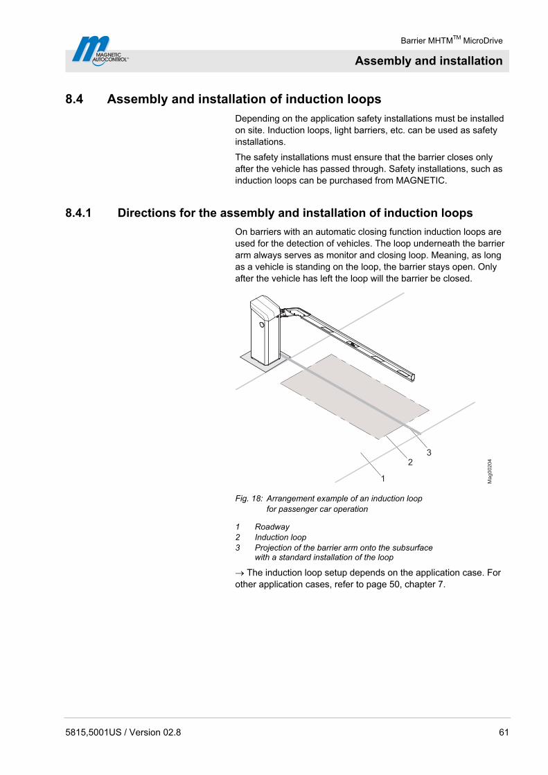
On barriers with an automatic closing function induction loops are used for the detection of vehicles. The loop underneath the barrier arm always serves as monitor and closing loop. Meaning, as long as a vehicle is standing on the loop, the barrier stays open. Only after the vehicle has left the loop will the barrier be closed.
1
23
Ma
g0
02
04
Fig. 18: Arrangement example of an induction loop for passenger car operation
1 Roadway 2 Induction loop 3 Projection of the barrier arm onto the subsurface
with a standard installation of the loop
The induction loop setup depends on the application case. For other application cases, refer to page 50, chapter 7.
Barrier MHTMTM MicroDrive
Assembly and installation
62 5815,5001US / Version 02.8
Please observe following points when installing the induction loop:
Loop geometry and clearances Install the loop symmetrically to the barrier arm. Please make sure that the barrier arm is attached to the side of the barrier housing.
The clearance of the safety loop for passenger cars in front of, and behind the barrier arm must be at least 19.7 in (500 mm). The safety loop for trucks must be dimensioned larger. See page 31, Fig. 3 to page 39, Fig. 6.
The distance of the induction loop from the roadside should be about 11.8 in to 19.7 in (300 to 500 mm).
Install opening loops right in front of the safety loop. The clearance between opening loop and safety loop must be not greater than 3.28 ft (1 m) for trucks and passenger cars.
If there are iron reinforcements, ramp heating etc. in the roadway, the induction loop must have a clearance of at least 1.97 in (50 mm) from those. Metals in the proximity of the induction loop affect the response sensitivity.
Avoid direct contact of induction loops with reinforcement and ramp heating.
Install induction loops with sufficient clearance from sliding gates, roller grilles etc.
Installation and ground conditions Please make sure when moulding or installing that the loop can not move anymore once it is in operation. Any geometric alteration will act as inductance change, which will set the detector to an error state.
Brittle road surfaces, loose pavements, gravel paths etc. are not suited for the application of induction loops.
Feed line The feed line to the loop must not exceed 49.2 ft (15 m).
The loop connection cable must protrude about 4.9 ft (1.5) m from the foundation.
Shorten the feed line to the loop to the proper length. The feed line must by no means be coiled.
The feed line must be twisted up to right in front of the terminals of the loop detector with ca. 6 twists per feet.

Barrier MHTMTM MicroDrive
Assembly and installation
5815,5001US / Version 02.8 63
8.4.2 Induction loops
The induction loops are available as ready assembled cables in various lengths from several manufacturers. Make sure that they meet the specification described in these operating instructions.
Alternatively a loop can be manufactured from single wire. The following requirements must be fulfilled:
Wire cross section: 18 to 16 AWG (0.75 to 1.5 mm2)
Inductivity of the loop: 70 to 500 H. This is equivalent to a loop with 3 to 6 windings.
When using hot pouring compounds, such as bitumen temperature resistant loop cables/strands must be used.
8.4.3 Testing induction loops
To verify the contact resistance, insulation resistance, and inductance of the loop these properties must be measured after installation:
Contact resistance: 0.8 to 2.0 ohms
Insulation resistance to earth: > 1 Mohm.
Inductivity of the loop: 70 to 500 μH
If the values are not within the specified ranges, the loop is defective.
8.4.4 Installing induction loops in bitumen, asphalt, or concrete
1. Cut a 1.97 in (50 mm) deep groove into the surface or asphalt using a cutting disc. The groove must be equally deep at every point. According to Fig. 14 the corners of the groove must be cut in a 45° angle.
M
ag
00
08
53
14
2
Fig. 19: Installing induction loop in bitumen, asphalt, or concrete
1 Groove for induction loop feed line 2 Corners cut diagonally 3 Groove for induction loop 4 Induction loop

Barrier MHTMTM MicroDrive
Assembly and installation
64 5815,5001US / Version 02.8
2. Lay the loop carefully into the groove and push it down by means of a blunt object, such as a piece of wood. The insulation must by no means be damaged.
3. To avoid slipping of the loop, fix the loop using small wooden wedges. Remove the wooden wedges later on.
4. Push the loop feed line through the empty conduit in place into the barrier housing.
5. Measure the induction loop according to chapter 8.4.3.
6. We recommend to cover the inserted loop using quartz sand. Make sure that at least 0.98 in (25 mm) remain between the upper edge of the roadway and the quartz sand for the potting compound.
7. Seal the groove with the potting compound.
The temperature resistance of the loop must match the temperature of the potting compound.
8. Allow the potting compound to cure.
S0104a
3
1
2
4
5
6
11.8(300)
5.91(150)
1.9
7(5
0)
1.1
8(3
0)
0.9
8(2
5)
Fig. 20: Installing induction loop in bitumen, asphalt, or concrete Dimensions in inch are without parenthesis. Dimensions in mm are in parenthesis.
1 Barrier housing 2 Groove with potting compound 3 Asphalt surface 4 Quartz sand filling 5 Loop cable 6 Foundation
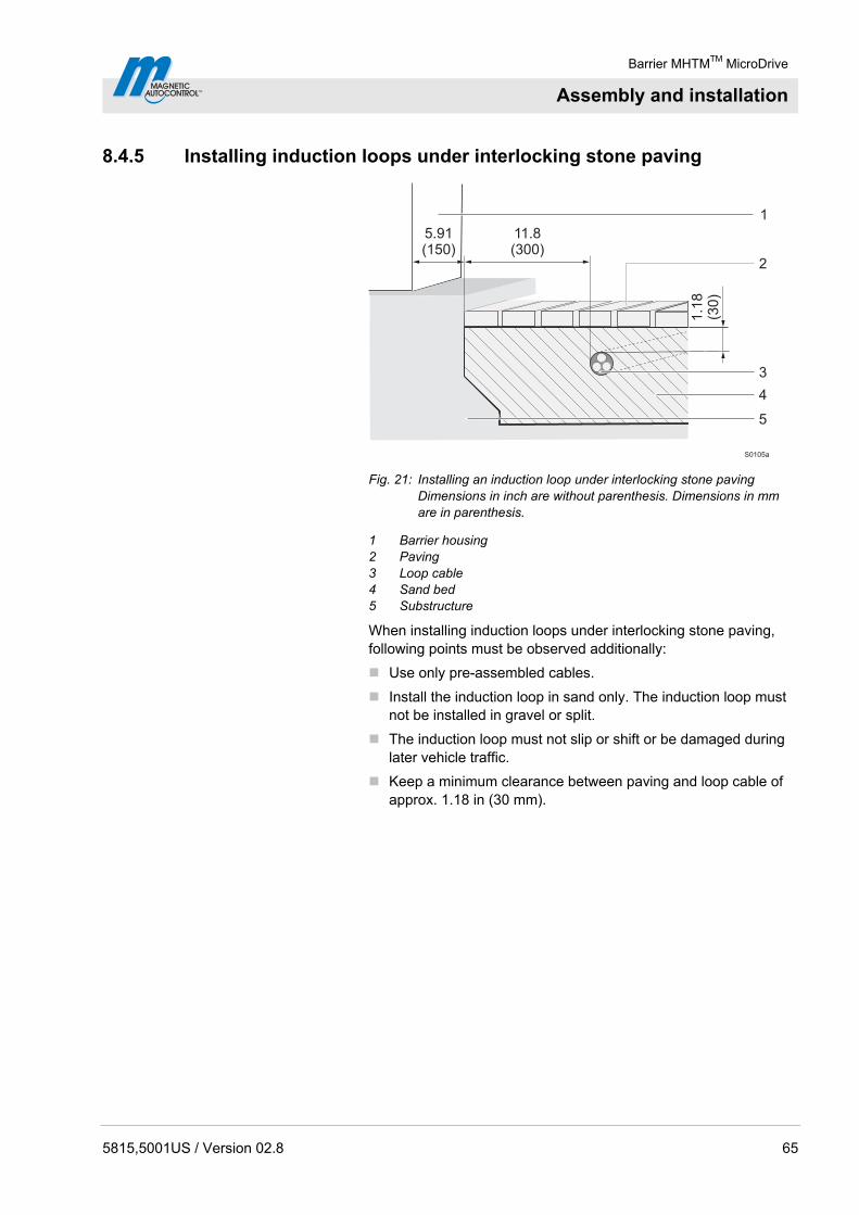
Barrier MHTMTM MicroDrive
Assembly and installation
5815,5001US / Version 02.8 65
8.4.5 Installing induction loops under interlocking stone paving
S0105a
3
1
4
5
2
11.8(300)
5.91(150)
1.1
8(3
0)
Fig. 21: Installing an induction loop under interlocking stone paving Dimensions in inch are without parenthesis. Dimensions in mm are in parenthesis.
1 Barrier housing 2 Paving 3 Loop cable 4 Sand bed 5 Substructure
When installing induction loops under interlocking stone paving, following points must be observed additionally:
Use only pre-assembled cables.
Install the induction loop in sand only. The induction loop must not be installed in gravel or split.
The induction loop must not slip or shift or be damaged during later vehicle traffic.
Keep a minimum clearance between paving and loop cable of approx. 1.18 in (30 mm).
Barrier MHTMTM MicroDrive
Assembly and installation
66 5815,5001US / Version 02.8
8.5 Unpacking
The individual packages are packed according to the expected transport conditions. Only environment-friendly materials have been used for the packaging.
The packaging should protect the individual components against transport damages, corrosion, etc up to the assembly. Therefore do not destroy the packaging and remove only directly before assembly.
1. Unpack barrier.
2. Set up barrier housing vertically.
3. Lay down barrier arm.
4. Unpack and lay out accessories.
5. Separate material according to type and size and recycle them after use.
8.6 Assemble housing
The barrier housing is attached by 4 foundation anchors via 2 attachment profiles. The attachment profiles are included in delivery.
Requirements mounting material MAGNETIC Automation Corporation recommends using 3/8" anchor bolts. Refer to the anchor bolt manufacturers installation requirements.
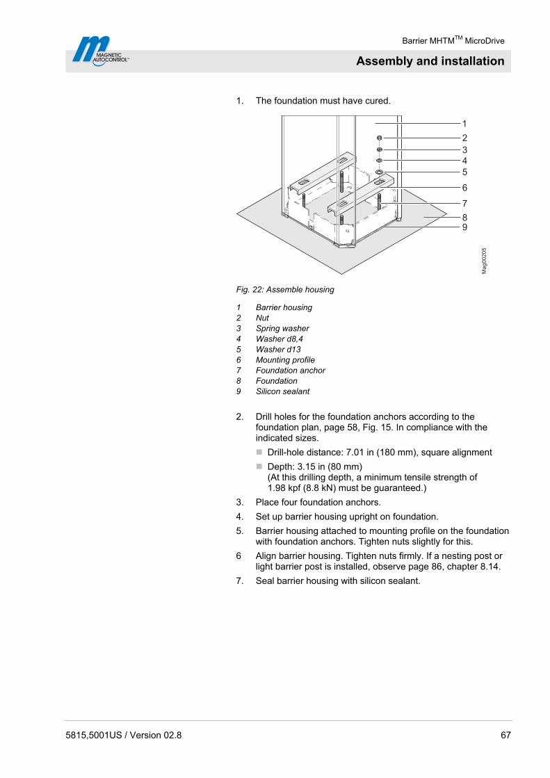
Barrier MHTMTM MicroDrive
Assembly and installation
5815,5001US / Version 02.8 67
1. The foundation must have cured.
8
1
2
5
6
7
43
9
Mag00205
Fig. 22: Assemble housing
1 Barrier housing 2 Nut 3 Spring washer 4 Washer d8,4 5 Washer d13 6 Mounting profile 7 Foundation anchor 8 Foundation 9 Silicon sealant
2. Drill holes for the foundation anchors according to the foundation plan, page 58, Fig. 15. In compliance with the indicated sizes.
Drill-hole distance: 7.01 in (180 mm), square alignment
Depth: 3.15 in (80 mm) (At this drilling depth, a minimum tensile strength of 1.98 kpf (8.8 kN) must be guaranteed.)
3. Place four foundation anchors.
4. Set up barrier housing upright on foundation.
5. Barrier housing attached to mounting profile on the foundation with foundation anchors. Tighten nuts slightly for this.
6 Align barrier housing. Tighten nuts firmly. If a nesting post or light barrier post is installed, observe page 86, chapter 8.14.
7. Seal barrier housing with silicon sealant.
Barrier MHTMTM MicroDrive
Assembly and installation
68 5815,5001US / Version 02.8
8.7 Assemble light barrier post
The light barrier post is attached with 4 foundation anchors each.
Requirements mounting material MAGNETIC Automation Corporation recommends using 3/8" anchor bolts. Refer to the anchor bolt manufacturers installation requirements.
Assemble light barrier post 1. The foundation must have cured.
2. Drill holes for the foundation anchors according to the foundation plan, page 60, Fig. 17. In compliance with the indicated sizes.
Drill-hole distance: 3.94 in (100 mm), square alignment
Depth: 3.15 in (80 mm) (At this drilling depth, a minimum tensile strength of 2.02 kpf (9 kN) must be guaranteed.)
3. Set four foundation anchors.
4. Set up post upright on foundation.
5. Attach the post to the foundation with the anchor bolts and tighten the nuts securely.

Barrier MHTMTM MicroDrive
Assembly and installation
5815,5001US / Version 02.8 69
8.8 Assemble safety light barrier
Only MAGNETIC safety light barriers must be used.
8.8.1 Assemble transmitter
A B
B
Ma
g0
02
24
A
4
3
1
2
1
C
6.3
0(1
60)
0.6
7(1
7)
11.0
2(2
80)
11.5
0(2
92)Ø 0.51
(Ø 13)
Ø 24(Ø 6)
Ø 0.24(Ø 6)
0.59 (15)
1.18 (30)
3.94 (100)
17.3
2(4
40)
~
6.3
0(1
60)
1.18 (30)
0.6
7(1
7)
Ø 0.51(Ø 13)
11.0
2(2
80)
11.5
0(2
92)
0.59 (15)
2.76 (70)
Ø 24(Ø 6)
Ø 0.24(Ø 6)
Fig. 23: Assemble the receiver's light barrier housing on the barrier
housing Dimensions in inch or feet are without parenthesis. Dimensions in mm are in parenthesis.
A View A B View B C Light barrier housing transmitter 1 Hexagon socket screws 5 AF 2 Transmitter 3 Transmitter connection line 4 Cable screw connection
1. Drill holes for the light barrier housing according to Fig. 14.
2. Mount the cable screws at the housing with locknuts.
3. Connect connection line for transmitter to the control unit.
4. Guide connection line through cable screws.
5. Mount light barrier housing to housing with the hexagon socket screws 5 AF.
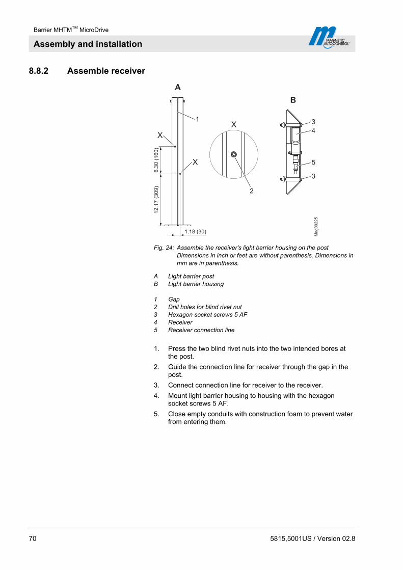
Barrier MHTMTM MicroDrive
Assembly and installation
70 5815,5001US / Version 02.8
8.8.2 Assemble receiver
6.3
0(1
60
)1
2.1
7(3
09
)
1.18 (30)
X
X
X
Mag00225
3
4
5
3
A
1
2
B
Fig. 24: Assemble the receiver's light barrier housing on the post Dimensions in inch or feet are without parenthesis. Dimensions in mm are in parenthesis.
A Light barrier post B Light barrier housing 1 Gap 2 Drill holes for blind rivet nut 3 Hexagon socket screws 5 AF 4 Receiver 5 Receiver connection line
1. Press the two blind rivet nuts into the two intended bores at the post.
2. Guide the connection line for receiver through the gap in the post.
3. Connect connection line for receiver to the receiver.
4. Mount light barrier housing to housing with the hexagon socket screws 5 AF.
5. Close empty conduits with construction foam to prevent water from entering them.

Barrier MHTMTM MicroDrive
Assembly and installation
5815,5001US / Version 02.8 71
8.9 Assemble barrier arm type "VarioBoom"
The barrier arm type "VarioBoom" is delivered in two parts.
Short barrier arm profile with assembled connection plates, half-shells and end caps.
Long barrier arm profile
The mounting material is included in delivery.
1. Remove transport rubber bands.
2. Disassemble the two half-shells from the short barrier arm profile.
3. Slide long barrier arm profile over the two connection plates.
4. Attach long barrier arm profile to both connection plates with the 4 Torx. The larger bores must remain free.
5. Attach the two half-shells with the washers and the hexagon socket screws.
8.10 Assemble edge protection
Missing edge protection at the barrier arm
WARNING!
WARNING! Danger from missing edge protection at the barrier arm!
Missing edge protection at the barrier arm may cause severe or lethal injury for persons, bicyclers and cabriolet drivers when the barrier arm closes!
Therefore:
– Assemble edge protection.
– If the edge protection is damaged, it must be replaced immediately.
NOTE!
If you use a pendulum support, observe that you must mount part of the edge protection in front of the pendulum support and part of the edge protection behind the pendulum support.

Barrier MHTMTM MicroDrive
Assembly and installation
72 5815,5001US / Version 02.8
The edge protection is included in the delivery loosely in 6.56 ft (2 m) pieces. If the barrier was ordered with the light strips option, the barrier arm is delivered with the mounted edge protection.
The number of edge protections is according to the length of the long barrier arm profile.
1. Measure the length of the long barrier arm profile.
2. Shorten edge protection to the required length with a saw. When the length of the barrier arm profile is, for example, 11.5 ft (3.5 m), saw off one edge protection to 4.92 ft (1.5 m).
3. Moisten lower half of the barrier arm onto which the edge protection is pushed with water.
4. Slide edge protection in the barrier arm groove.
5. Slide further edge protections into the intended groove until the edge protection ends flush with the barrier arm.
8.11 Assembling flange and barrier arm
Danger of injury
CAUTION!
CAUTION! Danger of injury!
There is a danger of injury when mounting the barrier arm.
Therefore:
– Barrier arms as of a length of 14.8 ft (4.5 m) must be installed by two persons. We recommend also installing shorter barrier arms with two persons.
8.11.1 Type "VarioBoom" and "MicroBoom"
Do not grease
NOTICE!
NOTICE! Improper lubrication of components, in particular the counter bearing or flange shaft, may lead to damage of the equipment!
Therefore:
– Do not grease the counter bearing and flange shaft.
1. Secure barrier danger area e.g. with barrier tape.
2. Remove the barrier housing hood.
3. Remove the barrier housing door.
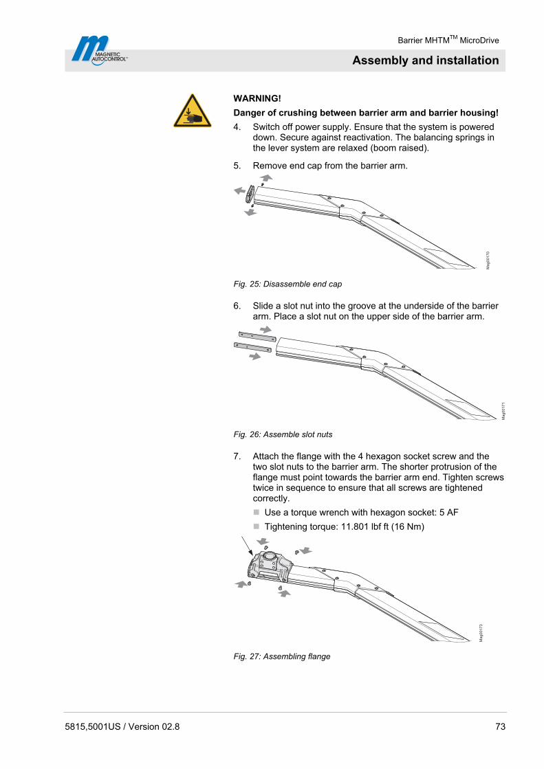
Barrier MHTMTM MicroDrive
Assembly and installation
5815,5001US / Version 02.8 73
WARNING!
Danger of crushing between barrier arm and barrier housing!
4. Switch off power supply. Ensure that the system is powered down. Secure against reactivation. The balancing springs in the lever system are relaxed (boom raised).
5. Remove end cap from the barrier arm.
Mag00170
Fig. 25: Disassemble end cap
6. Slide a slot nut into the groove at the underside of the barrier arm. Place a slot nut on the upper side of the barrier arm.
Ma
g0
01
71
Fig. 26: Assemble slot nuts
7. Attach the flange with the 4 hexagon socket screw and the two slot nuts to the barrier arm. The shorter protrusion of the flange must point towards the barrier arm end. Tighten screws twice in sequence to ensure that all screws are tightened correctly.
Use a torque wrench with hexagon socket: 5 AF
Tightening torque: 11.801 lbf ft (16 Nm)
Ma
g0
01
73
Fig. 27: Assembling flange
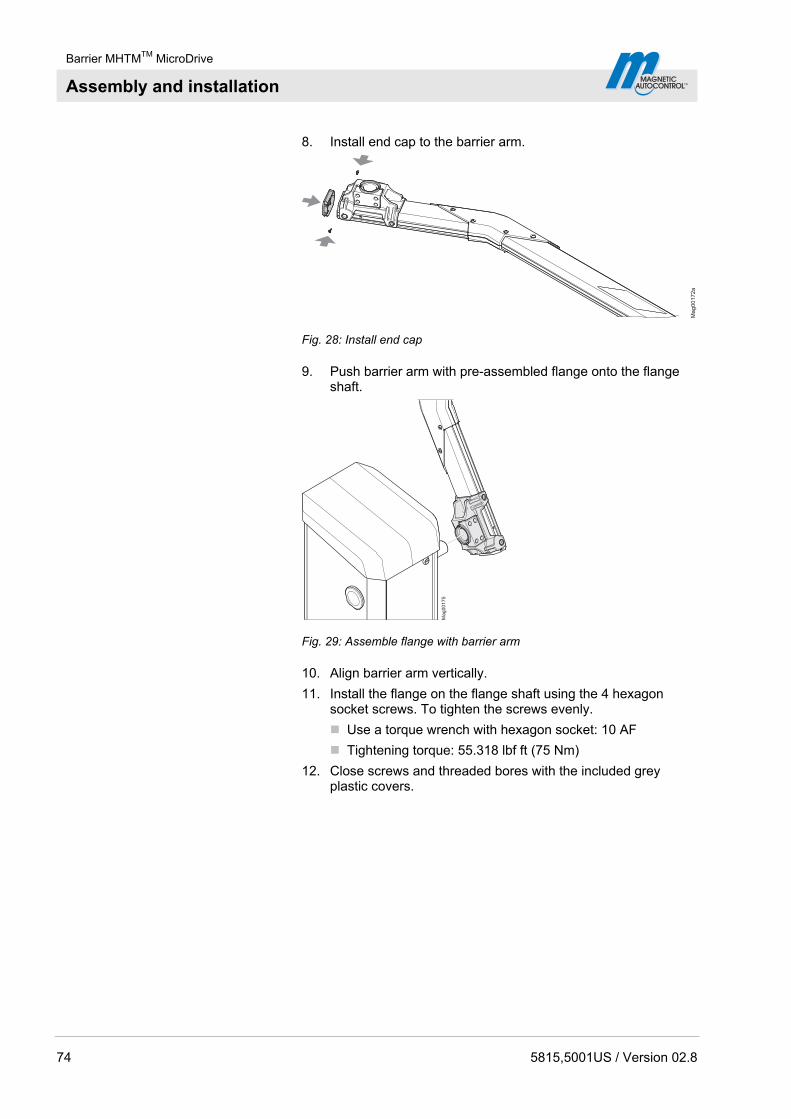
Barrier MHTMTM MicroDrive
Assembly and installation
74 5815,5001US / Version 02.8
8. Install end cap to the barrier arm.
Mag00172a
Fig. 28: Install end cap
9. Push barrier arm with pre-assembled flange onto the flange shaft.
Ma
g0
01
75
Fig. 29: Assemble flange with barrier arm
10. Align barrier arm vertically.
11. Install the flange on the flange shaft using the 4 hexagon socket screws. To tighten the screws evenly.
Use a torque wrench with hexagon socket: 10 AF
Tightening torque: 55.318 lbf ft (75 Nm)
12. Close screws and threaded bores with the included grey plastic covers.

Barrier MHTMTM MicroDrive
Assembly and installation
5815,5001US / Version 02.8 75
13. Push the barrier into the top-most position. The clamping lever must be at the stop for the "open" position. If required, push straight through the upper tool bore with a tool to press the lever arm from the dead point. See page 171, chapter 13.5.
14. Check the vertical alignment of the barrier arm with a level and correct with the hexagon socket screws at the flange if necessary.
15. Switch on power supply.
16. Switch the "Service" switch on the control unit. The LED lights red. The display backlighting flashes. See page 123, chapter 10.7.7 Mode "Service".
17. Close the control unit with the middle right button at the control unit.
18. Check the horizontal alignment of the barrier arm with a level and correct with the hexagon socket screws at the flange if necessary.
19. Switch the "Service" switch on the control unit. The LED must light green.
20. Switch off power supply.
21. Install the barrier housing door.
22. Attach and lock the barrier housing hood.
8.11.2 Barrier arm type "MicroBoom-T"
1. Secure barrier danger area e.g. with barrier tape.
2. Remove the barrier housing hood.
3. Remove the barrier housing door.
WARNING!
Danger of crushing between barrier arm and barrier housing!
4. Switch off power supply. Ensure that the system is powered down. Secure against reactivation. The balancing springs in the lever system are relaxed (boom raised).

Barrier MHTMTM MicroDrive
Assembly and installation
76 5815,5001US / Version 02.8
5. Install the flange on the flange plates with the 2 hexagon socket screws 8 AF. Make sure:
Tighten the screws evenly with a tightening torque of 44.254 lbf ft (60 Nm).
That the air gap between flange and flange plate must be consistent.
Mag00265
Fig. 30: Install flange to flange plate
6. Slide steel sleeve into the intended bore in the barrier arm.
7. Place barrier arm in the flange so that the barrier arm can be assembled.
8. Assemble barrier arm with hexagon screw, washer and hexagon nut.
Mag00266
Fig. 31: Assemble barrier arm

Barrier MHTMTM MicroDrive
Assembly and installation
5815,5001US / Version 02.8 77
9. Push the barrier into the top-most position. The clamping lever must be at the stop for the "open" position. If required, push straight through the upper tool bore with a tool to press the lever arm from the dead point. See page 171, chapter 13.5.
10. Check the vertical alignment of the barrier arm with a level and correct with the hexagon socket screws at the flange if necessary.
11. Switch on power supply.
12. Switch the "Service" switch on the control unit. The LED lights red. The display backlighting flashes. See page 123, chapter 10.7.7 Mode "Service".
13. Close the barrier with the middle right button at the control unit.
14. Check the horizontal alignment of the barrier arm with a level and correct with the hexagon socket screws at the flange if necessary.
15. Switch the "Service" switch on the control unit. The LED must light green.
16. Switch off power supply.
17. Install the barrier housing door.
18. Attach and lock the barrier housing hood.

Barrier MHTMTM MicroDrive
Assembly and installation
78 5815,5001US / Version 02.8
8.12 Conversion "left version" – "right version" (VarioBoom and MicroBoom)
Danger of injury
CAUTION!
CAUTION! Danger of injury!
There is a danger of injury when mounting the barrier arm.
Therefore:
– Barrier arm as of a length of 14.8 ft (4.5 m) must be installed by two persons. We recommend also installing shorter barrier arms with two persons.
Do not grease
NOTICE!
NOTICE! Improper lubrication of components, in particular the counter bearing or flange shaft, may lead to damage of the equipment!
Therefore:
– Do not grease the counter bearing and flange shaft.
All MHTMTM MicroDrive barriers are available as "left version" and "right version". See type code, page 30 and as of page 31, Fig. 3 to Fig. 6.
If required, you can also remove the barrier arm yourself from one side of the barrier housing and replace it on the other.
1. Secure barrier danger area e.g. with barrier tape.
2. Remove the barrier housing hood.
3. Remove the barrier housing door.
WARNING!
Danger of crushing between barrier arm and barrier housing!
4. Switch off power supply. Ensure that the system is powered down. Secure against reactivation. The balancing springs in the lever system are relaxed (boom raised).
5. The barrier must be open. Open barrier arm manually if required.
6. Disassemble flange from the flange shaft together with the barrier arm. For this, loosen the 4 hexagon socket screws 10 AF at the flange.
7. Remove the flange with the barrier arm.
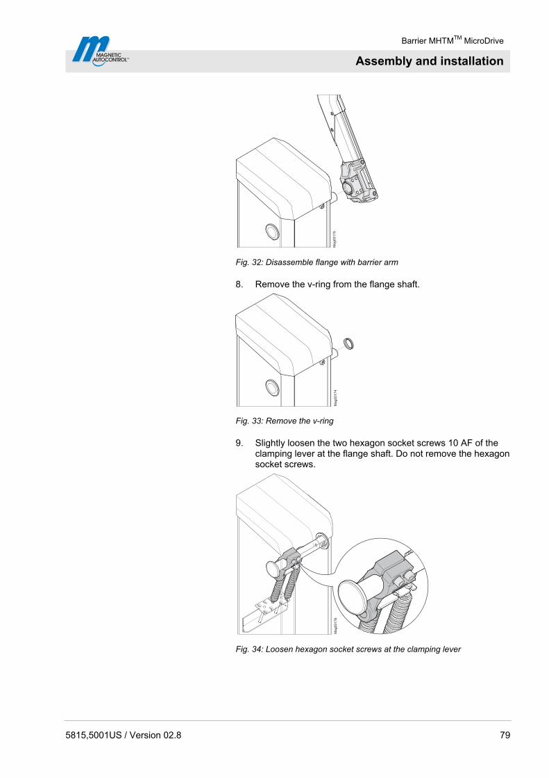
Barrier MHTMTM MicroDrive
Assembly and installation
5815,5001US / Version 02.8 79
Ma
g0
01
75
Fig. 32: Disassemble flange with barrier arm
8. Remove the v-ring from the flange shaft.
Mag00174
Fig. 33: Remove the v-ring
9. Slightly loosen the two hexagon socket screws 10 AF of the clamping lever at the flange shaft. Do not remove the hexagon socket screws.
Mag00176
Fig. 34: Loosen hexagon socket screws at the clamping lever

Barrier MHTMTM MicroDrive
Assembly and installation
80 5815,5001US / Version 02.8
10. Unhook the balancing springs in the lever system. For this, press a tool straight through the upper tool bore. The lever arm is pressed from the upper dead point. See page 171, chapter 13.5.
11. Remove the flange shaft cover disc of the barrier housing. Push a long rod through the flange shaft for this and slightly push it against the cover.
12. Push the flange shaft to the other side by turning. The flange shaft must be flush with the counter bearing on the side where the barrier is not mounted. The flange shaft points out of the barrier housing by approx. 2.44 in (62 mm) on the other side.
13. Tighten the two hexagon socket screws of the clamping lever at the flange shaft.
Use a torque wrench with hexagon socket: 10 AF
Tightening torque: 88.508 lbf ft (120 Nm)
14. Hook in the balancing springs in the lever system.
15. Slip the v-ring over the flange shaft. The sealing lip points towards the barrier housing. See also page 79, Fig. 33.
16. Remove flange from the barrier arm. For this, loosen the 4 hexagon socket screws 5 AF at the barrier arm.
17. Attach the flange on the other side of the barrier arm. Observe position of the two slot nuts. The shorter protrusion of the flange must point towards the barrier arm end. See also page 74, Fig. 27.
Use a torque wrench with hexagon socket: 5 AF
Tightening torque: 11.801 lbf ft (16 Nm)
18. Push barrier arm with pre-assembled flange onto the flange shaft.
19. Align barrier arm vertically.
20. Install the flange on the flange shaft using the 4 hexagon socket screws. To tighten the screws evenly.
Use a torque wrench with hexagon socket: 10 AF
Tightening torque: 55.318 lbf ft (75 Nm)
21. Close screws and threaded bores with the included grey plastic covers.
22. Insert the cover disc for the flange shaft.
23. Push the barrier into the top-most position. The clamping lever must be at the stop for the "open" position. If required, push straight through the upper tool bore with a tool to press the lever arm from the dead point. See page 171, chapter 13.5.
24. Check the vertical alignment of the barrier arm with a level and correct with the hexagon socket screws at the flange if necessary.
25. Switch on power supply.

Barrier MHTMTM MicroDrive
Assembly and installation
5815,5001US / Version 02.8 81
26. Switch the "Service" switch on the control unit. The LED lights red. The display backlighting flashes. See page 123, chapter 10.7.7 Mode "Service".
27. Close the barrier with the middle right button at the control unit.
28. Check the horizontal alignment of the barrier arm with a level and correct with the hexagon socket screws at the flange if necessary.
29. Switch the "Service" switch on the control unit. The LED must light green.
30. Switch off power supply.
31. Install the barrier housing door.
32. Attach and lock the barrier housing hood.
8.13 Check and set the balancing springs in the lever system
Danger of crushing, lever system
WARNING!
WARNING! Danger of crushing at opened barrier housing at the lever system!
The lever system in the barrier housing can cause serious crushing injuries!
Therefore:
– Balancing springs in the lever system must only be checked and adjusted by specialised personnel.
– Balancing springs must only be checked and adjusted with the power supply turned off
– Wear protective gloves if necessary.
The lever system has balancing springs that exactly balance the barrier arm weight. These balancing springs are pre-set in the factory. The precise setting must be performed after assembly of the barrier arm and before commissioning.
The lever force is determined not only by the spring tension but also by the number of springs used and the spring rate. MAGNETIC uses two spring types. Depending on application case, you will have to set the spring tension, remove the springs, use additional springs or use springs with a different spring rate. Also see page 84, chapter 8.13.2.
In the "Power behaviour" menu, you can set the barrier behaviour in case of voltage failure. See page 137, chapter 10.10.9. The settings in this menu do not influence the settings of the balancing springs.
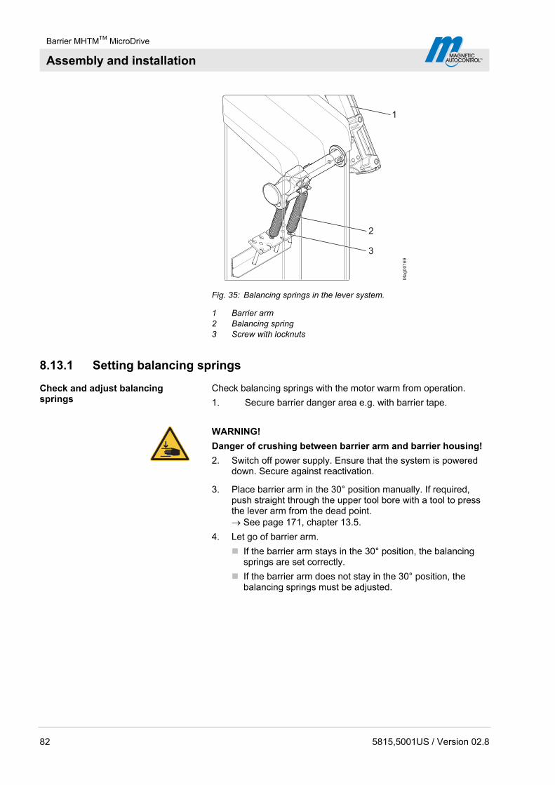
Barrier MHTMTM MicroDrive
Assembly and installation
82 5815,5001US / Version 02.8
Ma
g0
01
69
1
2
3
Fig. 35: Balancing springs in the lever system.
1 Barrier arm 2 Balancing spring 3 Screw with locknuts
8.13.1 Setting balancing springs
Check and adjust balancing springs
Check balancing springs with the motor warm from operation.
1. Secure barrier danger area e.g. with barrier tape.
WARNING!
Danger of crushing between barrier arm and barrier housing!
2. Switch off power supply. Ensure that the system is powered down. Secure against reactivation.
3. Place barrier arm in the 30° position manually. If required, push straight through the upper tool bore with a tool to press the lever arm from the dead point. See page 171, chapter 13.5.
4. Let go of barrier arm.
If the barrier arm stays in the 30° position, the balancing springs are set correctly.
If the barrier arm does not stay in the 30° position, the balancing springs must be adjusted.

Barrier MHTMTM MicroDrive
Assembly and installation
5815,5001US / Version 02.8 83
Adjust balancing springs:
5. Remove the barrier housing hood.
6. Remove the rear barrier housing door.
7. Adjust springs with a wrench via the screws with locknuts.
Barrier arm angle > approx. 30°: This balancing springs are tightened too far.
Barrier arm angle < approx. 30°: This balancing springs are not tightened enough.
8. Install the barrier housing door.
9. Attach and lock the barrier housing hood.
Ma
g0
02
76
30°
Fig. 36: Opening angle barrier arm 30°

Barrier MHTMTM MicroDrive
Assembly and installation
84 5815,5001US / Version 02.8
8.13.2 Overview table balancing springs
NOTE!
The following overview tables "Balancing springs" do not take into consideration any attachment parts. For barrier arms with attachment parts, the required number of springs may deviate from the number of springs in the overview table.
The following overview tables apply for barriers with VarioBoom.
Overview table balancing springs for barriers with VarioBoom and without pendulum support
Line width Number springs weak Number springs strong
4.9 to 5.6 ft (1.5 to 1.7 m) 1 –
5.9 to 7.6 ft (1.8 to 2.3 m) 2 –
7.9 to 9.5 ft (2.4 to 2.9 m) 3 –
9.8 to 11.2 ft (3.0 to 3.4 m) 4 –
11.5 to 12.8 ft (3.5 to 3.9 m) 5 –
13.1 to 14.1 ft (4.0 to 4.3 m) 6 –
14.4 to 15.1 ft (4.4 to 4.6 m) 7 –
15.4 to 16.4 ft (4.7 to 5.0 m) 8 –
16.7 to 17.4 ft (5.1 to 5.3 m) 9 –
17.7 ft (5.4 m) 5 2
18.1 to 19.0 ft (5.5 to 5.8 m) 5 3
19.4 to 19.7 ft (5.9 to 6.0 m) 6 3
Table 21: Overview table balancing springs for barriers with VarioBoom and without pendulum support
Overview table balancing springs for barrier with VarioBoom and with pendulum support
Line width Number springs weak Number springs strong
11.5 to 11.8 ft (3.5 to 3.6 m) 6 –
12.1 to 12.8 ft (3.7 to 3.9 m) 7 –
13.1 to 14.4 ft (4.0 to 4.4 m) 8 –
14.8 to 15.4 ft (4.5 to 4.7 m) 9 –
15.8 ft (4.8 m) 5 2
16.1 to 17.4 ft (4.9 to 5.3 m) 5 3
17.7 to 18.4 ft (5.4 to 5.6 m) 6 3
18.7 to 19.0 ft (5.7 to 5.8 m) 5 4
19.4 to 19.7 ft (5.9 to 6.0 m) 4 5
Table 22: Overview table balancing springs for barriers with VarioBoom and with pendulum support
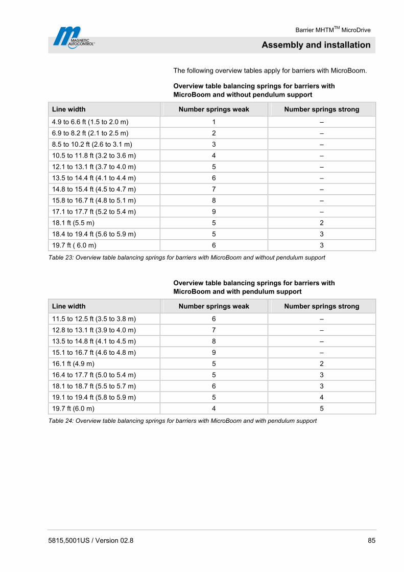
Barrier MHTMTM MicroDrive
Assembly and installation
5815,5001US / Version 02.8 85
The following overview tables apply for barriers with MicroBoom.
Overview table balancing springs for barriers with MicroBoom and without pendulum support
Line width Number springs weak Number springs strong
4.9 to 6.6 ft (1.5 to 2.0 m) 1 –
6.9 to 8.2 ft (2.1 to 2.5 m) 2 –
8.5 to 10.2 ft (2.6 to 3.1 m) 3 –
10.5 to 11.8 ft (3.2 to 3.6 m) 4 –
12.1 to 13.1 ft (3.7 to 4.0 m) 5 –
13.5 to 14.4 ft (4.1 to 4.4 m) 6 –
14.8 to 15.4 ft (4.5 to 4.7 m) 7 –
15.8 to 16.7 ft (4.8 to 5.1 m) 8 –
17.1 to 17.7 ft (5.2 to 5.4 m) 9 –
18.1 ft (5.5 m) 5 2
18.4 to 19.4 ft (5.6 to 5.9 m) 5 3
19.7 ft ( 6.0 m) 6 3
Table 23: Overview table balancing springs for barriers with MicroBoom and without pendulum support
Overview table balancing springs for barriers with MicroBoom and with pendulum support
Line width Number springs weak Number springs strong
11.5 to 12.5 ft (3.5 to 3.8 m) 6 –
12.8 to 13.1 ft (3.9 to 4.0 m) 7 –
13.5 to 14.8 ft (4.1 to 4.5 m) 8 –
15.1 to 16.7 ft (4.6 to 4.8 m) 9 –
16.1 ft (4.9 m) 5 2
16.4 to 17.7 ft (5.0 to 5.4 m) 5 3
18.1 to 18.7 ft (5.5 to 5.7 m) 6 3
19.1 to 19.4 ft (5.8 to 5.9 m) 5 4
19.7 ft (6.0 m) 4 5
Table 24: Overview table balancing springs for barriers with MicroBoom and with pendulum support
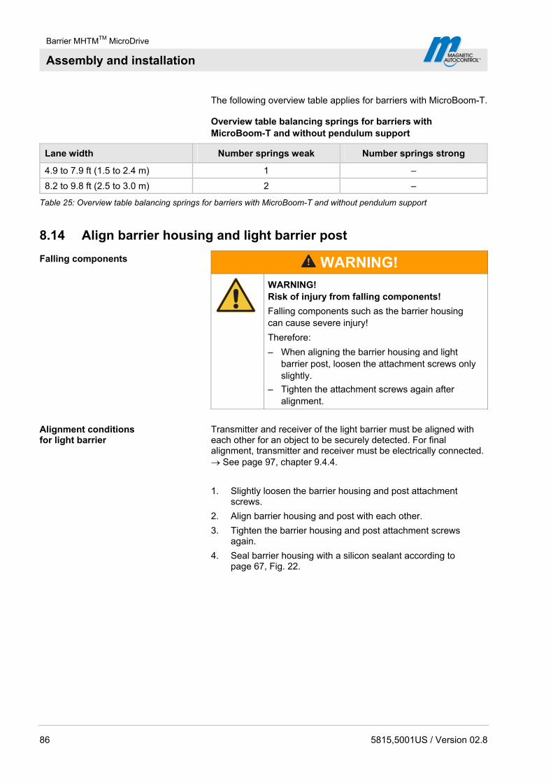
Barrier MHTMTM MicroDrive
Assembly and installation
86 5815,5001US / Version 02.8
The following overview table applies for barriers with MicroBoom-T.
Overview table balancing springs for barriers with MicroBoom-T and without pendulum support
Lane width Number springs weak Number springs strong
4.9 to 7.9 ft (1.5 to 2.4 m) 1 –
8.2 to 9.8 ft (2.5 to 3.0 m) 2 –
Table 25: Overview table balancing springs for barriers with MicroBoom-T and without pendulum support
8.14 Align barrier housing and light barrier post
Falling components
WARNING!
WARNING! Risk of injury from falling components!
Falling components such as the barrier housing can cause severe injury!
Therefore:
– When aligning the barrier housing and light barrier post, loosen the attachment screws only slightly.
– Tighten the attachment screws again after alignment.
Alignment conditions for light barrier
Transmitter and receiver of the light barrier must be aligned with each other for an object to be securely detected. For final alignment, transmitter and receiver must be electrically connected. See page 97, chapter 9.4.4.
1. Slightly loosen the barrier housing and post attachment screws.
2. Align barrier housing and post with each other.
3. Tighten the barrier housing and post attachment screws again.
4. Seal barrier housing with a silicon sealant according to page 67, Fig. 22.
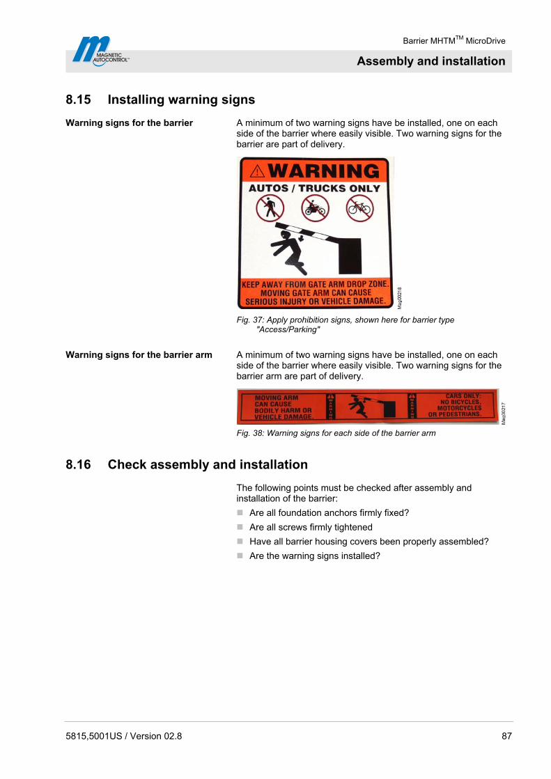
Barrier MHTMTM MicroDrive
Assembly and installation
5815,5001US / Version 02.8 87
8.15 Installing warning signs
Warning signs for the barrier A minimum of two warning signs have be installed, one on each side of the barrier where easily visible. Two warning signs for the barrier are part of delivery.
Fig. 37: Apply prohibition signs, shown here for barrier type "Access/Parking"
Warning signs for the barrier arm A minimum of two warning signs have be installed, one on each side of the barrier where easily visible. Two warning signs for the barrier arm are part of delivery.
Fig. 38: Warning signs for each side of the barrier arm
8.16 Check assembly and installation
The following points must be checked after assembly and installation of the barrier:
Are all foundation anchors firmly fixed?
Are all screws firmly tightened
Have all barrier housing covers been properly assembled?
Are the warning signs installed?

Barrier MHTMTM MicroDrive
Electrical connection
88 5815,5001US / Version 02.8
9 Electrical connection
9.1 Safety
See also safety notes on page 20, chapter 2.6 "Occupational safety and special dangers".
Electric voltage – inadequate qualification
DANGER!
DANGER! Mortal danger by electric voltage!
Risk of injury in case of inadequate qualification!
Therefore:
– Only electrical specialists may carry out work on the electrical system. Electrical specialists are able, due to their technical training, knowledge and experiences as well as knowledge of the relevant standards and regulations, to execute tasks on electrical systems and to independently recognize possible hazards. In Germany, the electrical specialist must comply with the provisions of accident prevention regulation BGV A3 (e.g. master electrical fitter). Appropriate regulations apply in other countries. The regulations valid there must be observed. The installation is to be made by a professional installer according to NFPA 70 National Electrical Code and Local Code.
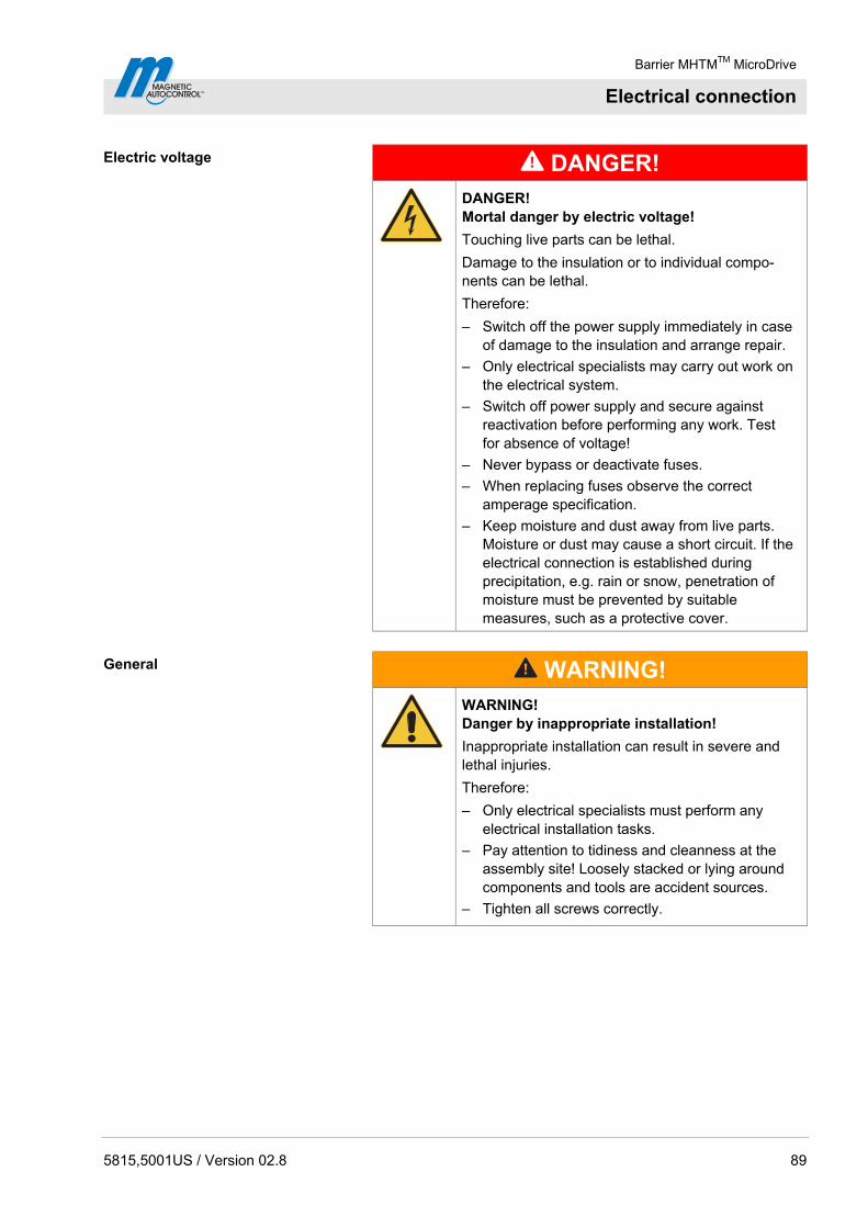
Barrier MHTMTM MicroDrive
Electrical connection
5815,5001US / Version 02.8 89
Electric voltage
DANGER!
DANGER! Mortal danger by electric voltage!
Touching live parts can be lethal.
Damage to the insulation or to individual compo-nents can be lethal.
Therefore:
– Switch off the power supply immediately in case of damage to the insulation and arrange repair.
– Only electrical specialists may carry out work on the electrical system.
– Switch off power supply and secure against reactivation before performing any work. Test for absence of voltage!
– Never bypass or deactivate fuses.
– When replacing fuses observe the correct amperage specification.
– Keep moisture and dust away from live parts. Moisture or dust may cause a short circuit. If the electrical connection is established during precipitation, e.g. rain or snow, penetration of moisture must be prevented by suitable measures, such as a protective cover.
General
WARNING!
WARNING! Danger by inappropriate installation!
Inappropriate installation can result in severe and lethal injuries.
Therefore:
– Only electrical specialists must perform any electrical installation tasks.
– Pay attention to tidiness and cleanness at the assembly site! Loosely stacked or lying around components and tools are accident sources.
– Tighten all screws correctly.

Barrier MHTMTM MicroDrive
Electrical connection
90 5815,5001US / Version 02.8
Hot surfaces
CAUTION!
CAUTION! Danger of burns!
The motor surface may be hot. Touching this hot surface can lead to burns.
Therefore:
– Do not touch these hot surfaces.
– After switching off the power supply wait some minutes until the motor has cooled down.
– Wear protective gloves if necessary.
Electromagnetic interference
NOTICE!
NOTICE! Electromagnetic interferences may cause malfunctions of the barrier or adjacent devices!
The barrier is approved for industrial, residential, commercial and business use. Operation in other electro-magnetic environmental conditions may cause interferences or malfunctions.
Therefore:
– Place control lines and mains cables into separate conduits
– Use cables according to the electrical circuit plan.
– Only install and apply additional parts approved by MAGNETIC.
– The electrical and electronically additional parts must be EMC verified and must not exceed the indicated EMC limits.
Personal protective equipment The following must be worn during all installation work:
Work clothes
Protective gloves
Safety shoes
Protective helmet.

Barrier MHTMTM MicroDrive
Electrical connection
5815,5001US / Version 02.8 91
9.2 Installing electrical protective devices
The safety installations that are required according to regional and local regulations must be provided by the customer. Usually these are:
Ground fault circuit interrupter (GFCI)
Circuit-breaker
Appropriate listed 2-pole main switch.
9.3 Connecting the mains supply
Electrical voltage
DANGER!
DANGER! Danger to life from electric shock!
If the mains supply is not connected to the terminal clamps correctly, loosens from the terminal clamps and touches the housing or door, there is a direct danger to life from electric shock.
Therefore:
– Have work at the electrical system only performed by electricians.
– Connect mains supply according to the following description.
– Install electrical protective devices according to chapter 9.2, national and local codes.
– Perform proper grounding.
NOTE!
The wire cross-section of the mains line must be between 16 and 12 AWG (1.5 and 4 mm2). Observe national provisions on line length and associated cable cross-section.
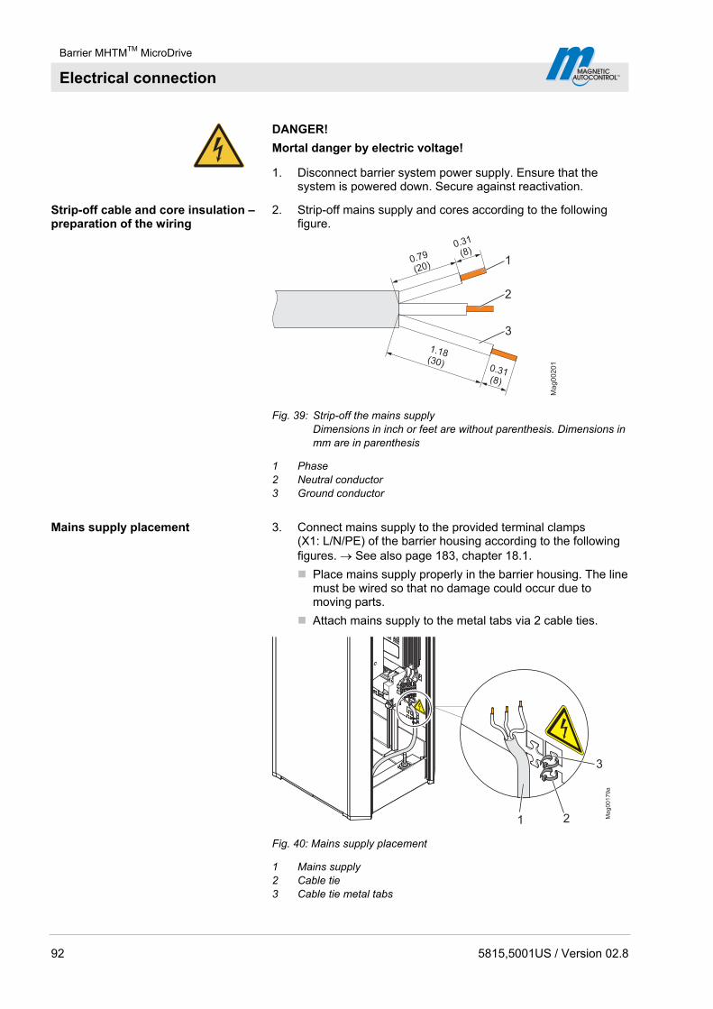
Barrier MHTMTM MicroDrive
Electrical connection
92 5815,5001US / Version 02.8
DANGER!
Mortal danger by electric voltage!
1. Disconnect barrier system power supply. Ensure that the system is powered down. Secure against reactivation.
Strip-off cable and core insulation – preparation of the wiring
2. Strip-off mains supply and cores according to the following figure.
Ma
g0
02
01
0.79
(20)
0.31
(8)
1.18(30)
0.31(8)
2
3
1
Fig. 39: Strip-off the mains supply Dimensions in inch or feet are without parenthesis. Dimensions in mm are in parenthesis
1 Phase 2 Neutral conductor 3 Ground conductor
Mains supply placement 3. Connect mains supply to the provided terminal clamps (X1: L/N/PE) of the barrier housing according to the following figures. See also page 183, chapter 18.1.
Place mains supply properly in the barrier housing. The line must be wired so that no damage could occur due to moving parts.
Attach mains supply to the metal tabs via 2 cable ties.
1
Fig. 40: Mains supply placement
1 Mains supply 2 Cable tie 3 Cable tie metal tabs

Barrier MHTMTM MicroDrive
Electrical connection
5815,5001US / Version 02.8 93
Connecting mains supply
Mag00207
12
3 4
Fig. 41: Connecting the mains supply
1 Terminal clamps for mains supply 2 Phase L 3 Neutral conductor N 4 Ground conductor PE
9.4 Connect customer's control lines (signalling devices)
The following connections are available for control and feedback on customer’s side:
8 Digital inputs for controlling the barrier.
4 Digital outputs to feed back information.
6 Relays outputs to feed back information. 3 Relays are normally-open contacts (NO) and 3 relays are change-over contacts.
DANGER!
Mortal danger by electric voltage!
1. Disconnect barrier system supply voltage. Ensure that there is no voltage applied. Secure against reactivation.
Connecting the control lines 2. Guide control lines into the connection space through the cable openings.
Place control lines properly in the barrier housing. The control lines must not get into moving components.
Attach control lines clamps and cable ties. The clamps can be removed from the rail by slight compression and relocated in the desired position. The cable ties can be attached to the metal tabs.
3. Connect control lines according to wiring diagram. Control lines must be wired so that no damage could occur due to moving parts. See page 183, chapter 18.1 "Wiring diagrams".
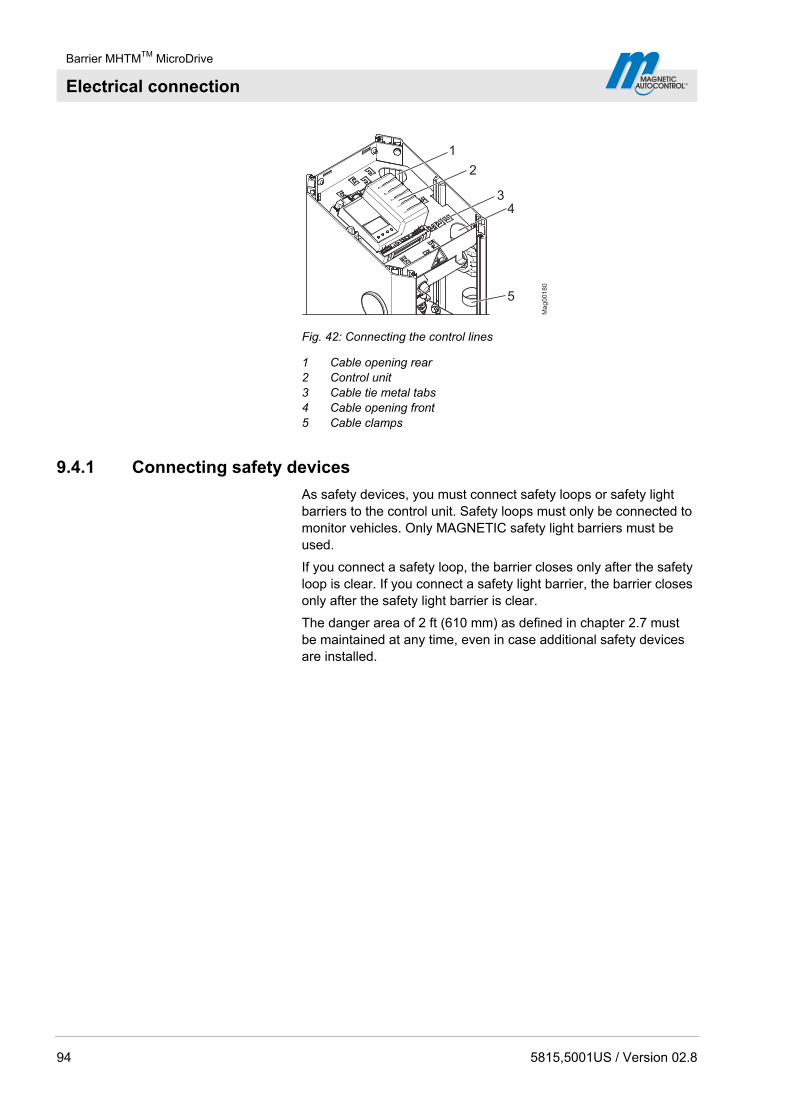
Barrier MHTMTM MicroDrive
Electrical connection
94 5815,5001US / Version 02.8
1
2
34
5
Ma
g0
01
80
Fig. 42: Connecting the control lines
1 Cable opening rear 2 Control unit 3 Cable tie metal tabs 4 Cable opening front 5 Cable clamps
9.4.1 Connecting safety devices
As safety devices, you must connect safety loops or safety light barriers to the control unit. Safety loops must only be connected to monitor vehicles. Only MAGNETIC safety light barriers must be used.
If you connect a safety loop, the barrier closes only after the safety loop is clear. If you connect a safety light barrier, the barrier closes only after the safety light barrier is clear.
The danger area of 2 ft (610 mm) as defined in chapter 2.7 must be maintained at any time, even in case additional safety devices are installed.
Barrier MHTMTM MicroDrive
Electrical connection
5815,5001US / Version 02.8 95
9.4.2 Plausibility check of the safety devices
NOTE!
The plausibility check is deactivated in barriers of the series "Toll" and barriers in deadman operation
with a closing speed of 2.2 seconds.
To prevent the barrier from being operated without safety devices, a plausibility check of the safety devices is performed.
The plausibility check inspects whether at least one safety device is present and whether the safety device works correctly in operation.
When the voltage supply is switched on, it is verified that at least one safety device was passed by a vehicle within three barrier openings. In operation, the number is increased to ten barrier openings.
If the plausibility check fails, the barrier is decommissioned for reasons of safety. The message "Safety device missing" appears on the display.
NOTE!
The input function "Safety devices" must only be used for additional safety devices. The input function is not considered for the plausibility check. A safety loop always has to be connected to the detector module or a testable safety light barrier to the clamps X11 and X20.
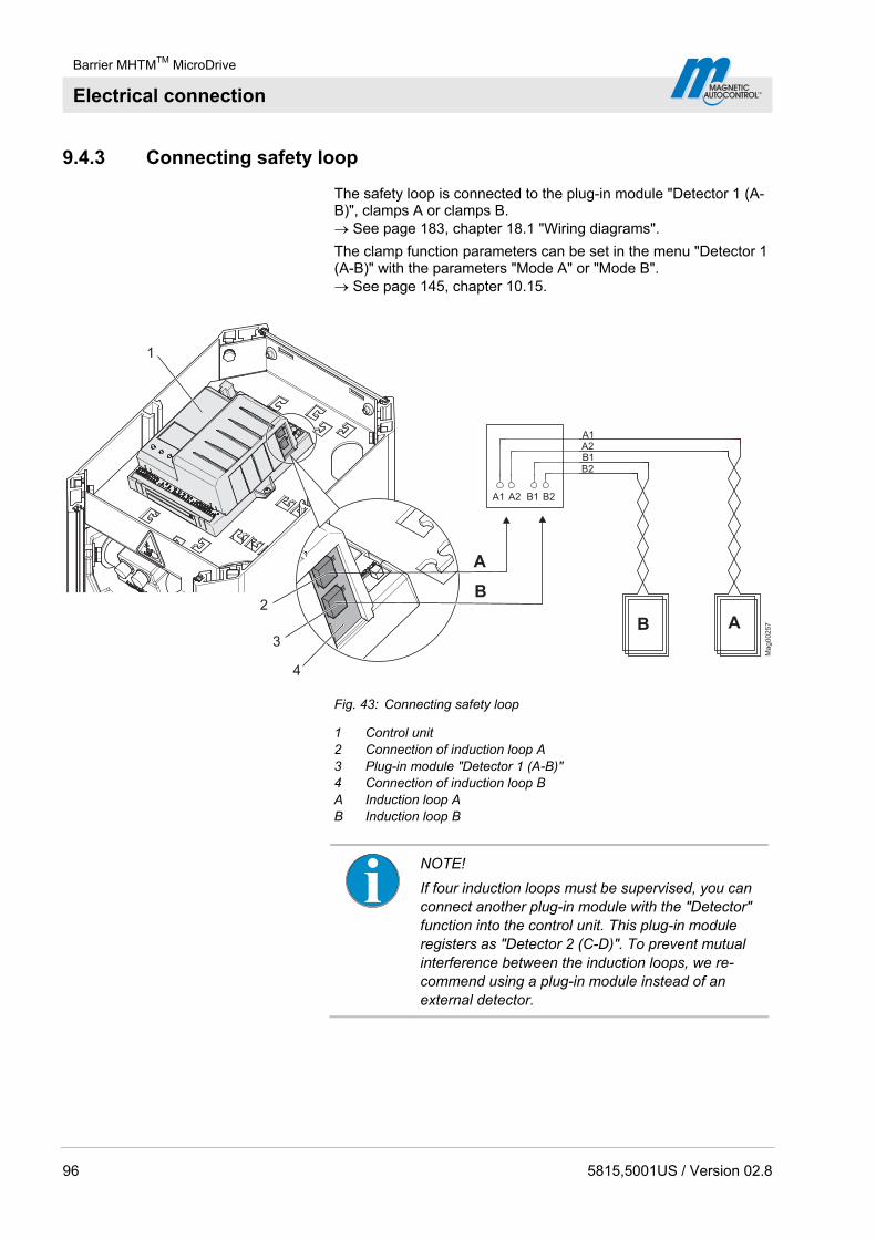
Barrier MHTMTM MicroDrive
Electrical connection
96 5815,5001US / Version 02.8
9.4.3 Connecting safety loop
The safety loop is connected to the plug-in module "Detector 1 (A-B)", clamps A or clamps B. See page 183, chapter 18.1 "Wiring diagrams".
The clamp function parameters can be set in the menu "Detector 1 (A-B)" with the parameters "Mode A" or "Mode B". See page 145, chapter 10.15.
A1 A2 B1 B2
A1A2B1B2
AB
Ma
g0
02
57
A
B
3
4
1
2
Fig. 43: Connecting safety loop
1 Control unit 2 Connection of induction loop A 3 Plug-in module "Detector 1 (A-B)" 4 Connection of induction loop B A Induction loop A B Induction loop B
NOTE!
If four induction loops must be supervised, you can connect another plug-in module with the "Detector" function into the control unit. This plug-in module registers as "Detector 2 (C-D)". To prevent mutual interference between the induction loops, we re-commend using a plug-in module instead of an external detector.
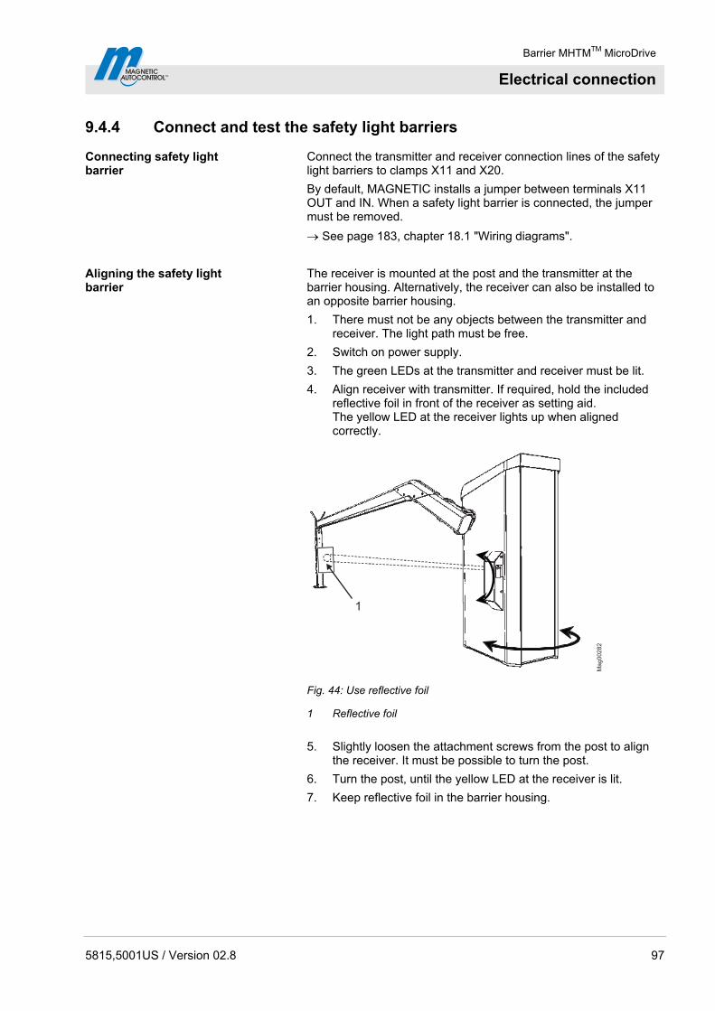
Barrier MHTMTM MicroDrive
Electrical connection
5815,5001US / Version 02.8 97
9.4.4 Connect and test the safety light barriers
Connecting safety light barrier
Connect the transmitter and receiver connection lines of the safety light barriers to clamps X11 and X20.
By default, MAGNETIC installs a jumper between terminals X11 OUT and IN. When a safety light barrier is connected, the jumper must be removed.
See page 183, chapter 18.1 "Wiring diagrams".
Aligning the safety light barrier
The receiver is mounted at the post and the transmitter at the barrier housing. Alternatively, the receiver can also be installed to an opposite barrier housing.
1. There must not be any objects between the transmitter and receiver. The light path must be free.
2. Switch on power supply.
3. The green LEDs at the transmitter and receiver must be lit.
4. Align receiver with transmitter. If required, hold the included reflective foil in front of the receiver as setting aid. The yellow LED at the receiver lights up when aligned correctly.
1M
ag
00
28
2
Fig. 44: Use reflective foil
1 Reflective foil
5. Slightly loosen the attachment screws from the post to align the receiver. It must be possible to turn the post.
6. Turn the post, until the yellow LED at the receiver is lit.
7. Keep reflective foil in the barrier housing.

Barrier MHTMTM MicroDrive
Electrical connection
98 5815,5001US / Version 02.8
Check safety light barrier function Perform function test by holding an object into the light path between the transmitter and receiver.
The following items must be met:
The yellow LED at the receiver must go out.
The barrier cannot be closed.
9.4.5 Connecting emergency opening contacts
Fire-fighter switch, emergency opening contacts, etc. are connected to the "Open high priority" input. When the signal is applied to this input, the barrier opens. While the signal is present, the barrier cannot be closed.
See page 91, chapter 9.4.6 "Digital inputs" and page 183, chapter 18.1 "Wiring diagrams".
9.4.6 Digital inputs
Improper parameterisation
WARNING!
WARNING! Risk of injury by improper parameterisation of the control unit!
Improper parameterisation of the control unit can lead to severe injuries!
Therefore:
– The parameterisation of the control unit may only be carried out by qualified personnel.
– The electrical connection of the signal generators to the IN1 to IN8 inputs must fit the parameterisation.
Technical data See page 41, chapter 4.5.
NOTE!
The digital input functions can be freely parameterised for the following versions:
– Access Pro, Access Pro L, Access Pro H, Access Select and Access Select L
– Parking Pro and Parking Select
For the remaining versions, the inputs are firmly assigned. → For output parameterisation, refer to page 106, chapter 10.

Barrier MHTMTM MicroDrive
Electrical connection
5815,5001US / Version 02.8 99
Factory setting
Clamp Description Function
IN1 Input 1 Open low priority
IN2 Input 2 Open low priority
IN3 Input 3 Opening with vend count
IN4 Input 4 Open high priority
IN5 Input 5 External opening loop exit
IN6 Input 6 Close
IN7 Input 7 Close
IN8 Input 8 Boom contact input
Table 26: Factory settings "Digital inputs"
The functions have different priorities towards each other. The function "Open high priority" has the highest priority (priority 1). I.e. all other functions, such as "Open low priority", "Close", etc. are ignored if the function "Open high priority" is active.
Function Description
Open high priority Connect fire fighter switch, emergency opening contacts, etc. to this input. This input has the highest priority. The barrier opens when +24 V DC are applied to this input. While the signal is present, the barrier cannot be closed. This input must not be used for opening loops. This input has prio-rity over all other input functions.
Open low priority Program modes
2, 4 to 8: Open low priority
Program mode 3: Close/Open
Depending on program mode, a permanent signal or pulse is required. Program modes 2, 4 to 8:
The barrier opens when +24 V DC are applied to this input. Program mode 3:
The barrier changes its state with every pulse, i.e. the barrier closes or opens.
Open exit 1) This function is used for selective counting, e.g. for permanent renters of a parking space.
Opening with vend count 1)
An internal vend count counts the pulses present at this input. The pulse must be present for approx. 100 to 300 ms. The reset behaviour of the vend count can be set by the "Reset behaviour" parameter.
Close Depending on program mode, a permanent signal or pulse is required. The barrier closes when +24 V DC are applied to this input.
Close low priority The function "Close low priority" is subordinated to all opening functions. The barrier closes when +24 V DC are applied to this input.
Inhibit opening When +24 V DC are applied to this input, all opening commands except for the "Open high priority" and "Open exit" signals are ignored. This input function has no function in the program mode 1 to 4.
Inhibit opening loop If the input function is active, the barrier remains closed when the opening loop is driven on.
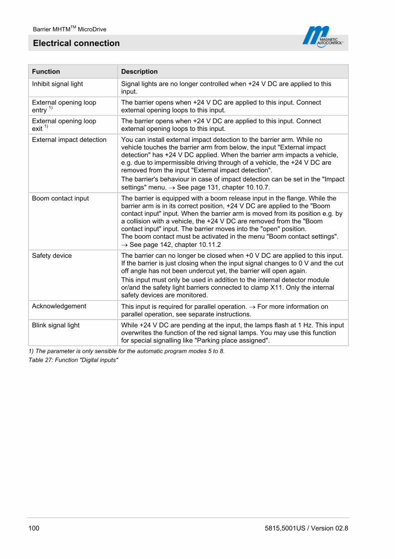
Barrier MHTMTM MicroDrive
Electrical connection
100 5815,5001US / Version 02.8
Function Description
Inhibit signal light Signal lights are no longer controlled when +24 V DC are applied to this input.
External opening loop entry 1)
The barrier opens when +24 V DC are applied to this input. Connect external opening loops to this input.
External opening loop exit 1)
The barrier opens when +24 V DC are applied to this input. Connect external opening loops to this input.
External impact detection You can install external impact detection to the barrier arm. While no vehicle touches the barrier arm from below, the input "External impact detection" has +24 V DC applied. When the barrier arm impacts a vehicle, e.g. due to impermissible driving through of a vehicle, the +24 V DC are removed from the input "External impact detection". The barrier's behaviour in case of impact detection can be set in the "Impact settings" menu. See page 131, chapter 10.10.7.
Boom contact input The barrier is equipped with a boom release input in the flange. While the barrier arm is in its correct position, +24 V DC are applied to the "Boom contact input" input. When the barrier arm is moved from its position e.g. by a collision with a vehicle, the +24 V DC are removed from the "Boom contact input" input. The barrier moves into the "open" position. The boom contact must be activated in the menu "Boom contact settings". See page 142, chapter 10.11.2
Safety device The barrier can no longer be closed when +0 V DC are applied to this input. If the barrier is just closing when the input signal changes to 0 V and the cut off angle has not been undercut yet, the barrier will open again. This input must only be used in addition to the internal detector module or/and the safety light barriers connected to clamp X11. Only the internal safety devices are monitored.
Acknowledgement This input is required for parallel operation. For more information on parallel operation, see separate instructions.
Blink signal light While +24 V DC are pending at the input, the lamps flash at 1 Hz. This input overwrites the function of the red signal lamps. You may use this function for special signalling like "Parking place assigned".
1) The parameter is only sensible for the automatic program modes 5 to 8.
Table 27: Function "Digital inputs"
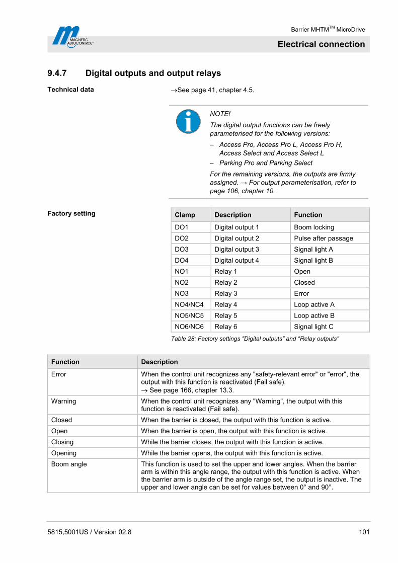
Barrier MHTMTM MicroDrive
Electrical connection
5815,5001US / Version 02.8 101
9.4.7 Digital outputs and output relays
Technical data See page 41, chapter 4.5.
NOTE!
The digital output functions can be freely parameterised for the following versions:
– Access Pro, Access Pro L, Access Pro H, Access Select and Access Select L
– Parking Pro and Parking Select
For the remaining versions, the outputs are firmly assigned. → For output parameterisation, refer to page 106, chapter 10.
Factory setting
Clamp Description Function
DO1 Digital output 1 Boom locking
DO2 Digital output 2 Pulse after passage
DO3 Digital output 3 Signal light A
DO4 Digital output 4 Signal light B
NO1 Relay 1 Open
NO2 Relay 2 Closed
NO3 Relay 3 Error
NO4/NC4 Relay 4 Loop active A
NO5/NC5 Relay 5 Loop active B
NO6/NC6 Relay 6 Signal light C
Table 28: Factory settings "Digital outputs" and "Relay outputs"
Function Description
Error When the control unit recognizes any "safety-relevant error" or "error", the output with this function is reactivated (Fail safe). See page 166, chapter 13.3.
Warning When the control unit recognizes any "Warning", the output with this function is reactivated (Fail safe).
Closed When the barrier is closed, the output with this function is active.
Open When the barrier is open, the output with this function is active.
Closing While the barrier closes, the output with this function is active.
Opening While the barrier opens, the output with this function is active.
Boom angle This function is used to set the upper and lower angles. When the barrier arm is within this angle range, the output with this function is active. When the barrier arm is outside of the angle range set, the output is inactive. The upper and lower angle can be set for values between 0° and 90°.
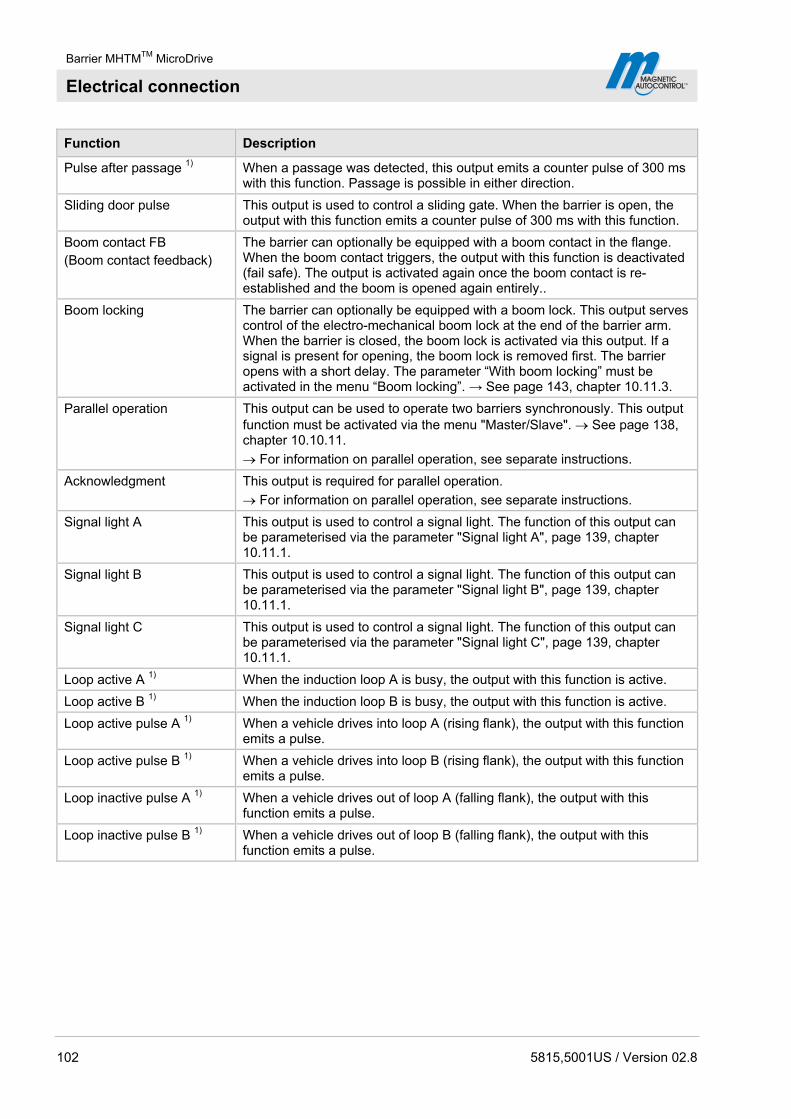
Barrier MHTMTM MicroDrive
Electrical connection
102 5815,5001US / Version 02.8
Function Description
Pulse after passage 1) When a passage was detected, this output emits a counter pulse of 300 ms with this function. Passage is possible in either direction.
Sliding door pulse This output is used to control a sliding gate. When the barrier is open, the output with this function emits a counter pulse of 300 ms with this function.
Boom contact FB (Boom contact feedback)
The barrier can optionally be equipped with a boom contact in the flange. When the boom contact triggers, the output with this function is deactivated (fail safe). The output is activated again once the boom contact is re-established and the boom is opened again entirely..
Boom locking The barrier can optionally be equipped with a boom lock. This output serves control of the electro-mechanical boom lock at the end of the barrier arm. When the barrier is closed, the boom lock is activated via this output. If a signal is present for opening, the boom lock is removed first. The barrier opens with a short delay. The parameter “With boom locking” must be activated in the menu “Boom locking”. → See page 143, chapter 10.11.3.
Parallel operation This output can be used to operate two barriers synchronously. This output function must be activated via the menu "Master/Slave". See page 138, chapter 10.10.11.
For information on parallel operation, see separate instructions.
Acknowledgment This output is required for parallel operation.
For information on parallel operation, see separate instructions.
Signal light A This output is used to control a signal light. The function of this output can be parameterised via the parameter "Signal light A", page 139, chapter 10.11.1.
Signal light B This output is used to control a signal light. The function of this output can be parameterised via the parameter "Signal light B", page 139, chapter 10.11.1.
Signal light C This output is used to control a signal light. The function of this output can be parameterised via the parameter "Signal light C", page 139, chapter 10.11.1.
Loop active A 1) When the induction loop A is busy, the output with this function is active.
Loop active B 1) When the induction loop B is busy, the output with this function is active.
Loop active pulse A 1) When a vehicle drives into loop A (rising flank), the output with this function emits a pulse.
Loop active pulse B 1) When a vehicle drives into loop B (rising flank), the output with this function emits a pulse.
Loop inactive pulse A 1) When a vehicle drives out of loop A (falling flank), the output with this function emits a pulse.
Loop inactive pulse B 1) When a vehicle drives out of loop B (falling flank), the output with this function emits a pulse.

Barrier MHTMTM MicroDrive
Electrical connection
5815,5001US / Version 02.8 103
Function Description
Direction 1 Pls A => B 1) The vehicle drives from direction A to B. When the vehicle leaves loop A in the direction of loop B, this output emits a counter pulse of 300 ms.
A B
DONO/NC
t = 300 ms
Ma
g0
011
3
Direction 1 Pls B => A 1) The vehicle drives from direction B to A. When the vehicle leaves loop B in the direction of loop A, this output emits a counter pulse of 300 ms.
A B
DONO/NC
t = 300 ms
Ma
g0
00
11
4
Direction 2 Pls A => B 1) The vehicle drives from direction A to B. When the vehicle drives on loop A in the direction of loop B, this output emits a counter pulse of 300 ms.
A B
DONO/NC
t = 300 ms
Ma
g0
011
5
Direction 2 Pls B => A 1) The vehicle drives from direction B to A. When the vehicle drives on loop B in the direction of loop A, this output emits a counter pulse of 300 ms.
A B
DONO/NC
t = 300 ms
Ma
g0
011
6
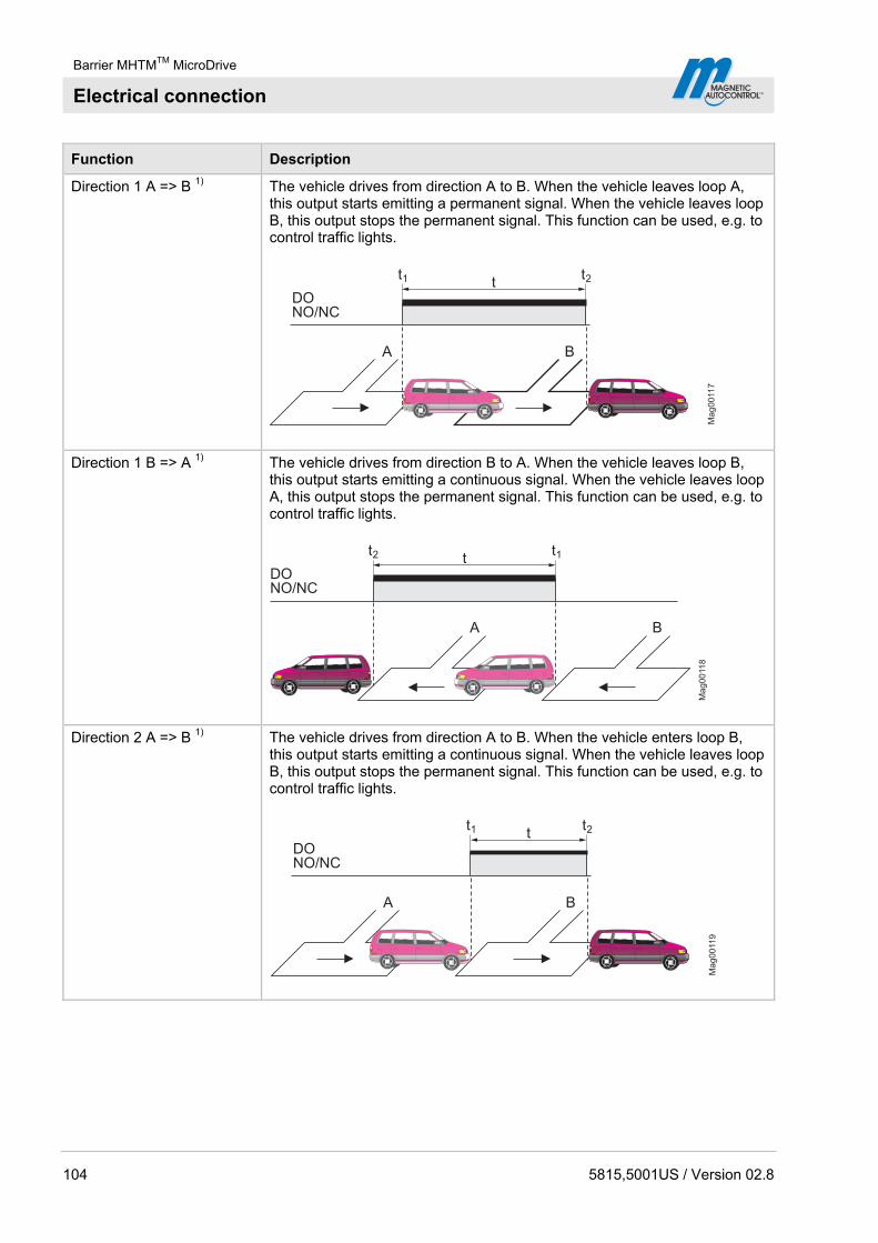
Barrier MHTMTM MicroDrive
Electrical connection
104 5815,5001US / Version 02.8
Function Description
Direction 1 A => B 1) The vehicle drives from direction A to B. When the vehicle leaves loop A, this output starts emitting a permanent signal. When the vehicle leaves loop B, this output stops the permanent signal. This function can be used, e.g. to control traffic lights.
A B
DONO/NC
t
Mag00117
t1 t2
Direction 1 B => A 1) The vehicle drives from direction B to A. When the vehicle leaves loop B, this output starts emitting a continuous signal. When the vehicle leaves loop A, this output stops the permanent signal. This function can be used, e.g. to control traffic lights.
A B
DONO/NC
t
Mag00118
t1t2
Direction 2 A => B 1) The vehicle drives from direction A to B. When the vehicle enters loop B, this output starts emitting a continuous signal. When the vehicle leaves loop B, this output stops the permanent signal. This function can be used, e.g. to control traffic lights.
A B
DONO/NC
t
Mag00119
t1 t2

Barrier MHTMTM MicroDrive
Electrical connection
5815,5001US / Version 02.8 105
Function Description
Direction 2 B => A 1) The vehicle drives from direction B to A. When the vehicle enters loop A, this output starts emitting a continuous signal. When the vehicle leaves loop A, this output stops the permanent signal. This function can be used, e.g. to control traffic lights.
A B
DONO/NC
t
Mag00120a
t1t2
Module-Open prior 2) This output function can be used to issue the command "Open high priority" of plug-in modules like "Ethernet", "Radio" or "RS485".
Module-Open 2) This output function can be used to issue the command "Open" of plug-in modules like "Ethernet", "Radio" or "RS485".
Module-Close 2) This output function can be used to issue the command "Close" of plug-in modules like "Ethernet", "Radio" or "RS485".
1) This function is only available with the plug-in module "Detector" plugged in.
2) This function is only available with the plug-in module "Ethernet", "Radio" or "RS485" plugged in.
Table 29: Function "Digital outputs" and "Output relay"
9.5 Checking the electrical connection
The following points have to be checked after the electrical installation of the barrier:
Are the following electrical protective devices installed: 2-pole main switch, circuit breaker and ground fault circuit interrupter?
Is the power cable connected to the terminal in compliance with chapter 9.3?
Are the induction loops connected according to the wiring diagram?
Are the safety light barriers connected according to the wiring diagram?
Are the control lines connected according to wiring diagram?
Have all barrier housing covers been properly assembled?
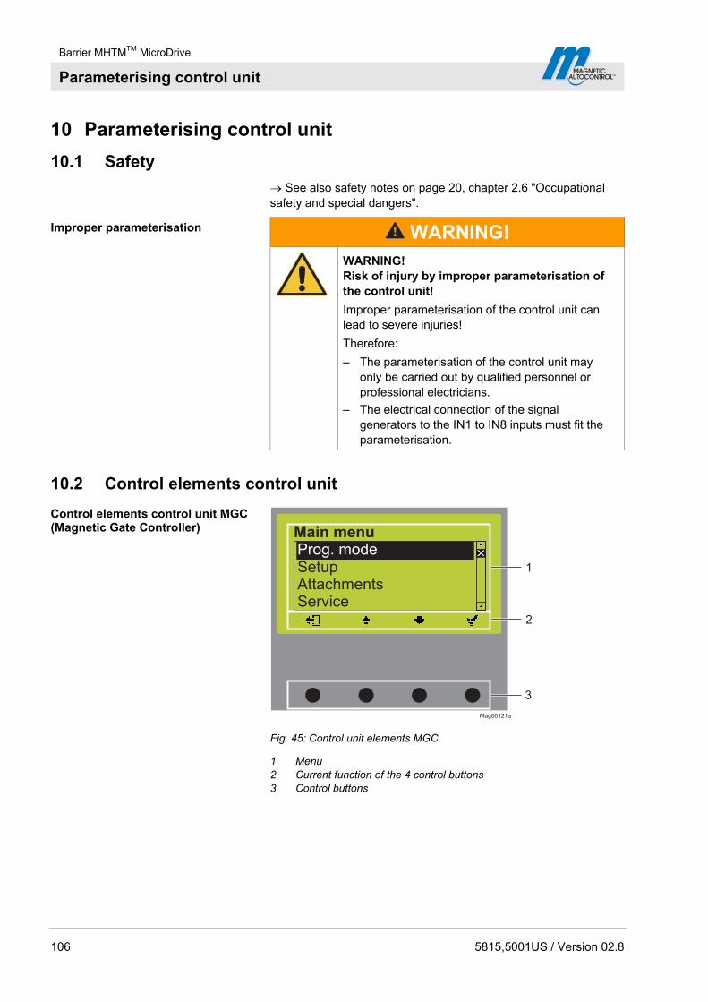
Barrier MHTMTM MicroDrive
Parameterising control unit
106 5815,5001US / Version 02.8
10 Parameterising control unit
10.1 Safety
See also safety notes on page 20, chapter 2.6 "Occupational safety and special dangers".
Improper parameterisation
WARNING!
WARNING! Risk of injury by improper parameterisation of the control unit!
Improper parameterisation of the control unit can lead to severe injuries!
Therefore:
– The parameterisation of the control unit may only be carried out by qualified personnel or professional electricians.
– The electrical connection of the signal generators to the IN1 to IN8 inputs must fit the parameterisation.
10.2 Control elements control unit
Control elements control unit MGC (Magnetic Gate Controller)
Mag00121a
1
3
2
Prog. modeSetupAttachmentsService
Main menu
Fig. 45: Control unit elements MGC
1 Menu 2 Current function of the 4 control buttons 3 Control buttons

Barrier MHTMTM MicroDrive
Parameterising control unit
5815,5001US / Version 02.8 107
10.3 Displays on the control unit
Example "Operational view"
Mag00126a
A B DC
Access
Select4
456
1 2 3
Fig. 46: Example "Operational view"
1 Program mode, here program mode 4 2 Barrier type, here type "Access Select" 3 Current state of the barrier, here barrier closed 4 Current function of the right control button,
here calling menu "Main menu" 5 Current state of the induction loops 6 Current function of the left control button,
here calling menu "Information"
Example "Screen change value"
Mag00129a
60
315
5
3
4sek
1 2
Hold-open time
Fig. 47: Example "View – Change value"
1 Parameter 2 Current value 3 Possible upper value 4 Possible lower value 5 Current functions control buttons
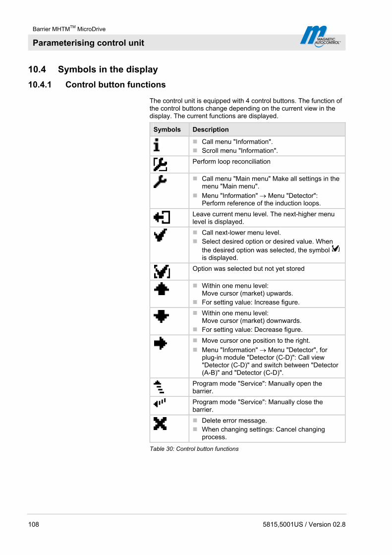
Barrier MHTMTM MicroDrive
Parameterising control unit
108 5815,5001US / Version 02.8
10.4 Symbols in the display
10.4.1 Control button functions
The control unit is equipped with 4 control buttons. The function of the control buttons change depending on the current view in the display. The current functions are displayed.
Symbols Description
Call menu "Information". Scroll menu "Information".
Perform loop reconciliation
Call menu "Main menu" Make all settings in the
menu "Main menu".
Menu "Information" Menu "Detector": Perform reference of the induction loops.
Leave current menu level. The next-higher menu level is displayed.
Call next-lower menu level. Select desired option or desired value. When
the desired option was selected, the symbol is displayed.
Option was selected but not yet stored
Within one menu level:
Move cursor (market) upwards. For setting value: Increase figure.
Within one menu level:
Move cursor (market) downwards. For setting value: Decrease figure.
Move cursor one position to the right.
Menu "Information" Menu "Detector", for plug-in module "Detector (C-D)": Call view "Detector (C-D)" and switch between "Detector (A-B)" and "Detector (C-D)".
Program mode "Service": Manually open the barrier.
Program mode "Service": Manually close the barrier.
Delete error message. When changing settings: Cancel changing
process.
Table 30: Control button functions

Barrier MHTMTM MicroDrive
Parameterising control unit
5815,5001US / Version 02.8 109
10.4.2 Current state of the barrier
The barrier can have the following states:
Symbols Description
Barrier arm closed.
Barrier arm open.
Barrier arm opens.
Closing signal was recognized. Traffic lights active. Barrier closes in 5 seconds. Time for traffic light lead is counted down.
Barrier arm closes.
Monitoring unit used.
Barrier arm position unknown. "Homing" active.
Barrier arm stopped
An error is present.
Table 31: Current state of the barrier
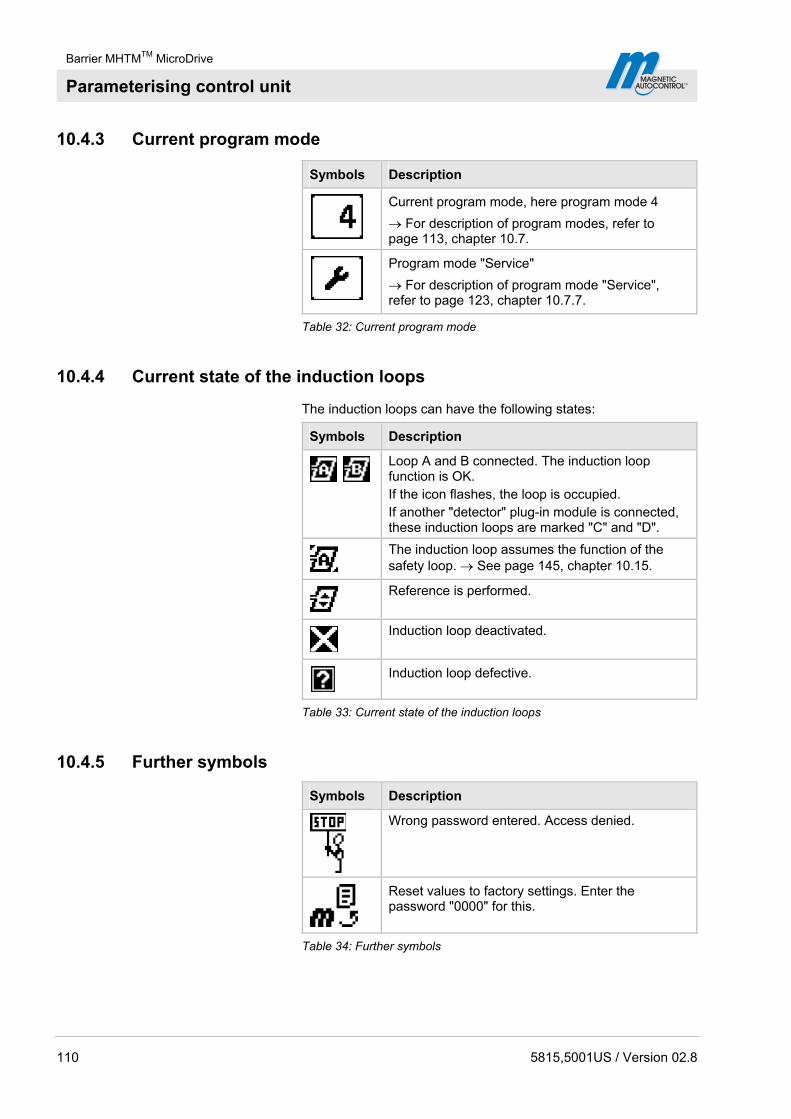
Barrier MHTMTM MicroDrive
Parameterising control unit
110 5815,5001US / Version 02.8
10.4.3 Current program mode
Symbols Description
Current program mode, here program mode 4
For description of program modes, refer to page 113, chapter 10.7.
Program mode "Service"
For description of program mode "Service", refer to page 123, chapter 10.7.7.
Table 32: Current program mode
10.4.4 Current state of the induction loops
The induction loops can have the following states:
Symbols Description
Loop A and B connected. The induction loop function is OK. If the icon flashes, the loop is occupied. If another "detector" plug-in module is connected, these induction loops are marked "C" and "D".
The induction loop assumes the function of the safety loop. See page 145, chapter 10.15.
Reference is performed.
Induction loop deactivated.
Induction loop defective.
Table 33: Current state of the induction loops
10.4.5 Further symbols
Symbols Description
Wrong password entered. Access denied.
Reset values to factory settings. Enter the password "0000" for this.
Table 34: Further symbols
Barrier MHTMTM MicroDrive
Parameterising control unit
5815,5001US / Version 02.8 111
10.5 Parameterising options
Menu setup, refer to page 191.
Program modes overview, refer to page 113.
Example: Select program mode 1. The operating view is displayed. See page 107, Fig. 46.
2. Press right control button .
3. The "Main menu" menu is displayed.
4. The "Program mode" menu is highlighted with a dark background and therefore selected. If required, select the "Program mode" menu with the two middle buttons , .
5. Confirm selection with the right control button .
6. A list with the possible program modes is displayed.
7. Select the desired program mode with the two middle buttons , .
8. Use the right button to select the new programming mode. Your selection is marked with the symbol .
9. Use the left button to leave the "Program mode" menu.
10. The safety prompt "Save changes?" appears.
If the changes are to be saved, press the right button . The new program mode is activated.
If the changes are not to be saved, press the left button . The previous program mode remains active.
11. The "Main menu" menu is displayed.
12. Use the left button to leave the "Main menu" menu. The operating view is displayed.

Barrier MHTMTM MicroDrive
Parameterising control unit
112 5815,5001US / Version 02.8
10.6 Parameterising values
Example: Change hold-open time 1. The operating view is displayed. See page 107, Fig. 46.
2. Press right control button .
3. The "Main menu" menu is displayed.
4. Select the menu "Setup" with the two middle buttons , .
5. Confirm selection with the right control button .
6. Select the menu "Delays" with the two middle buttons , .
7. Press right control button .
8. The "Hold-open time" parameter is highlighted with a dark background and therefore selected. If required, select the "Hold-open time" parameter with the two middle buttons ,
.
9. Press right control button .
10. The current hold-open time value is displayed. The cursor flashes on the first digit.
11. Use the middle buttons , to set the desired digit.
12. Use the right button to move the cursor to the right.
13. The cursor flashes on the second digit.
14. Use the middle buttons , to set the desired digit.
15. Press the right button .
16. Use the left button to leave the "Hold-open time" parameter.
17. The safety prompt "Save changes?" appears.
If the changes are to be saved, press the right button . The new hold-open time is activated.
If the changes are not to be saved, press the left button . The previous hold-open time remains active.
18. The "Delays" menu is displayed.
19. Press the left button repeatedly until the operating view is displayed again.

Barrier MHTMTM MicroDrive
Parameterising control unit
5815,5001US / Version 02.8 113
10.7 Select program mode
8 program modes and the service mode are available for the MHTMTM MicroDrive barriers.
Program modes 1 to 4 are manual modes. In the manual modes, the barrier must be closed manually after a drive through.
Program modes 5 to 8 are automatic modes. In the automatic modes, the barrier closes again automatically after a vehicle drives through.
Program Description
1 Maintained contact
2 Deadman
3 Pulse control (bistable)
4 Two-Pulse control (Open/Closed button) (Factory setting)
5 Automatic (5): with hold-open time
6 Automatic (6): with hold-open time and decoupling of the opening loop at drive through in the opposite direction
7 Automatic (7): without hold-open time
8 Automatic (8) without hold-open time and decoupling of the opening loop at drive through in the opposite direction
Service
Table 35: Program modes
Another program mode can be selected pursuant to chapter 10.5, page 111.
NOTE!
For reasons of safety, the first barrier arm motion after program mode change is performed at slow speed.

Barrier MHTMTM MicroDrive
Parameterising control unit
114 5815,5001US / Version 02.8
10.7.1 Mode 1: Maintained contact
Typical application This mode is suitable, e.g. for parallel operation of two barriers. See page 138, chapter 10.10.11 "Master/Slave".
Function The barrier is controlled only by one switch.
When the switch is closed, the barrier closes. When the switch is opened, the barrier opens.
Supported input functions
Input function Signal type Supported/ Not supported
Open low priority – Not supported
Open low priority with vend count
– Not supported
Open high priority (priority 1)
Pulse signal Supported
Opening loop – Not supported
Close (priority 2)
Permanent signal Supported
Table 36: Supported input functions "Maintained contact"
See page 98, chapter 9.4.6 "Digital inputs".

Barrier MHTMTM MicroDrive
Parameterising control unit
5815,5001US / Version 02.8 115
10.7.2 Mode 2: Deadman
Typical application This mode is suitable for barriers on parking places, factory premises, etc. The barrier must be operated by a person.
Function The barrier is operated by two buttons.
For opening the barrier, the button "open" must be pressed until the barrier is open all the way. For closing the barrier the button "close" must be pressed until the barrier is closed.
If no button is pressed, the barrier stops. If the "close" button is then pressed, the barrier opens completely first for safety reasons and then closes.
If the closing process is interrupted, only opening will be possible. A signal at the "Close" input would in this case open the barrier. If the "Close" signal is removed, the opening process is interrupted. If there is a pulse at the "Open high priority" input, the barrier opens completely.
Supported input functions Input function Signal type Supported/ Not supported
Open low priority (priority 3)
Permanent signal Supported
Open low priority with vend count
– Not supported
Open high priority (priority 1)
Pulse signal Supported
Opening loop – Not supported
Close (priority 2)
Permanent signal Supported
Table 37: Supported input functions "Deadman"
See page 98, chapter 9.4.6 "Digital inputs".
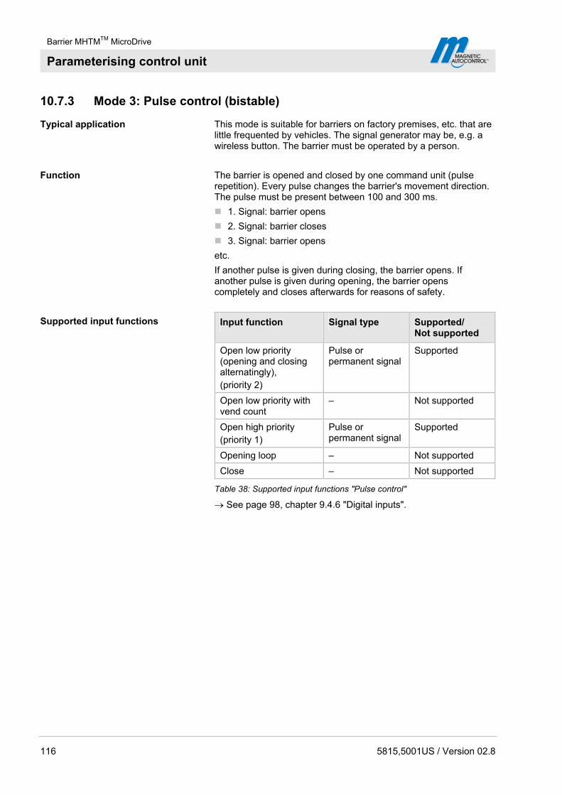
Barrier MHTMTM MicroDrive
Parameterising control unit
116 5815,5001US / Version 02.8
10.7.3 Mode 3: Pulse control (bistable)
Typical application This mode is suitable for barriers on factory premises, etc. that are little frequented by vehicles. The signal generator may be, e.g. a wireless button. The barrier must be operated by a person.
Function The barrier is opened and closed by one command unit (pulse repetition). Every pulse changes the barrier's movement direction. The pulse must be present between 100 and 300 ms.
1. Signal: barrier opens
2. Signal: barrier closes
3. Signal: barrier opens
etc.
If another pulse is given during closing, the barrier opens. If another pulse is given during opening, the barrier opens completely and closes afterwards for reasons of safety.
Supported input functions Input function Signal type Supported/ Not supported
Open low priority (opening and closing alternatingly), (priority 2)
Pulse or permanent signal
Supported
Open low priority with vend count
– Not supported
Open high priority (priority 1)
Pulse or permanent signal
Supported
Opening loop – Not supported
Close – Not supported
Table 38: Supported input functions "Pulse control"
See page 98, chapter 9.4.6 "Digital inputs".

Barrier MHTMTM MicroDrive
Parameterising control unit
5815,5001US / Version 02.8 117
10.7.4 Mode 4: Two-Pulse control (bistable)
Typical application This mode is suitable for barriers on factory premises, etc. that are often frequented by vehicles. The barrier must be operated by a person.
Function The barrier is opened and closed completely via two separate command units (signal). One pulse on the respective input is sufficient for opening or closing. The pulse must be present between 100 and 300 ms.
The input function "Open high priority" is superordinated to the input function "Close". This means that while a closing signal is applied, the barrier can be opened by the signal “Open high priority”. When the opening signal is removed, the barrier closes again at once after opening completely.
Supported input functions Input function Signal type Supported/ Not supported
Open low priority Pulse or permanent signal
Supported
Open low priority with vend count
Pulse signal Supported
Open high priority Pulse or permanent signal
Supported
Opening loop – Not supported
Close Pulse or permanent signal
Supported
Table 39: Supported input functions "Two-Pulse control"
See page 98, chapter 9.4.6 "Digital inputs".
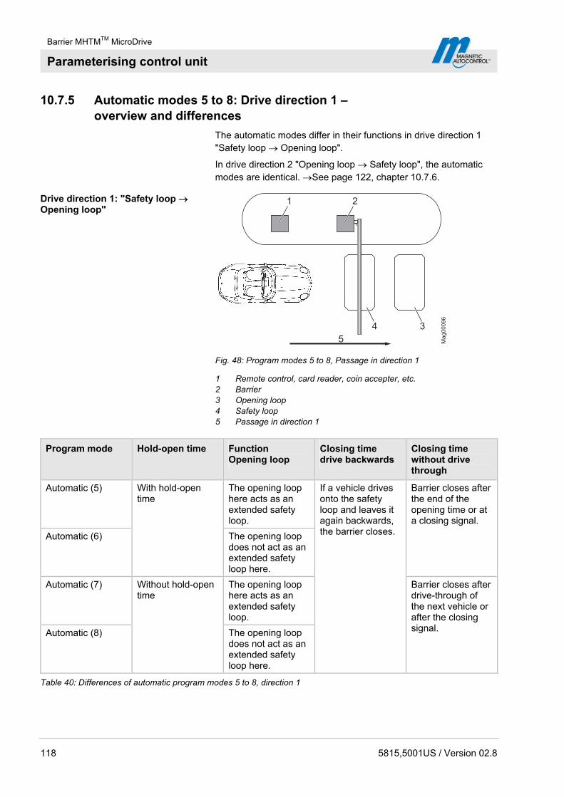
Barrier MHTMTM MicroDrive
Parameterising control unit
118 5815,5001US / Version 02.8
10.7.5 Automatic modes 5 to 8: Drive direction 1 – overview and differences
The automatic modes differ in their functions in drive direction 1 "Safety loop Opening loop".
In drive direction 2 "Opening loop Safety loop", the automatic modes are identical. See page 122, chapter 10.7.6.
Drive direction 1: "Safety loop Opening loop"
Mag00096
1 2
34
5
Fig. 48: Program modes 5 to 8, Passage in direction 1
1 Remote control, card reader, coin accepter, etc. 2 Barrier 3 Opening loop 4 Safety loop 5 Passage in direction 1
Program mode Hold-open time Function Opening loop
Closing time drive backwards
Closing time without drive through
Automatic (5) The opening loop here acts as an extended safety loop.
Automatic (6)
With hold-open time
The opening loop does not act as an extended safety loop here.
Barrier closes after the end of the opening time or at a closing signal.
Automatic (7) The opening loop here acts as an extended safety loop.
Automatic (8)
Without hold-open time
The opening loop does not act as an extended safety loop here.
If a vehicle drives onto the safety loop and leaves it again backwards, the barrier closes.
Barrier closes after drive-through of the next vehicle or after the closing signal.
Table 40: Differences of automatic program modes 5 to 8, direction 1

Barrier MHTMTM MicroDrive
Parameterising control unit
5815,5001US / Version 02.8 119
Mode 5: Automatic (5) Typical application
This mode is suitable for the automatic operation of a barrier, e.g. with card readers, remote control, coin accepters and induction loops or light barriers. Passage of the barrier is possible in either direction
Function
The barrier is opened from direction 1 "Safety loop Opening loop" with a pulse at the "Open low priority" pulse, e.g. with a card reader or coin accepter. The hold-open time that was set is also started.
When the vehicle leaves the safety loop, the hold-open time is deleted.
The barrier closes in the following cases:
If the vehicle drives over both loops in direction 1, the barrier closes as soon as the vehicle leaves the opening loop. The opening loop here acts as an extended safety loop.
If a vehicle drives onto the safety loop but leaves it again backwards, the barrier closes at once.
If the vehicle drives over neither of the two loops, i.e. there is no drive through, the barrier closes after the end of the hold-open time.
For barriers with a safety light barrier but no safety loop installed, see page 138, chapter 10.10.10.
Mode 6: Automatic (6) Typical application
This mode is suitable for the automatic operation of a barrier, e.g. with card readers, remote control, coin accepters and induction loops or light barriers. Passage of the barrier is possible in either direction.
Function
The barrier is opened from direction 1 "Safety loop Opening loop" with a pulse at the "Open low priority" pulse, e.g. with a card reader or coin accepter. The hold-open time that was set is also started.
When the vehicle leaves the safety loop, the hold-open time is deleted.

Barrier MHTMTM MicroDrive
Parameterising control unit
120 5815,5001US / Version 02.8
The barrier closes in the following cases:
If the vehicle drives over both loops in direction 1 "Safety loop Opening loop", the barrier closes as soon as the vehicle leaves the safety loop. The opening loop here does not act as an extended safety loop.
If a vehicle drives onto the safety loop but leaves it again backwards, the barrier closes.
If the vehicle drives over neither of the two loops, i.e. there is no drive through, the barrier closes after the end of the hold-open time.
For barriers with a safety light barrier but no safety loop installed, see page 138, chapter 10.10.10.
Mode 7: Automatic (7) Typical application
This mode is suitable for the automatic operation of a barrier, e.g. with ticket vending machines with internal logic. Passage of the barrier is possible in either direction
Function
From direction 1 "Safety loop Opening loop", the barrier is opened by an opening signal at one of the digital opening inputs. Hold-open time is not active in this mode.
The barrier closes in the following cases:
If the vehicle drives over both loops in direction 1, the barrier closes as soon as the vehicle leaves the opening loop. The opening loop here acts as an extended safety loop.
If a vehicle drives onto the safety loop but leaves it again backwards, the barrier closes.
If the vehicle does not drive onto any of the two loops, the barrier remains open until a vehicle drives through or a closing signal is given.
For barriers with a safety light barrier but no safety loop installed, see page 138, chapter 10.10.10.
Mode 8: Automatic (8) Typical application
This mode is suitable for the automatic operation of a barrier, e.g. with ticket vending machines with internal logic. Passage of the barrier is possible in either direction.
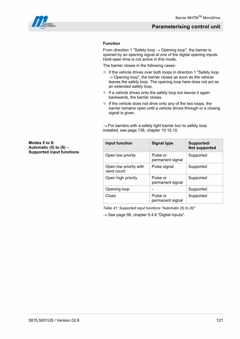
Barrier MHTMTM MicroDrive
Parameterising control unit
5815,5001US / Version 02.8 121
Function
From direction 1 "Safety loop Opening loop", the barrier is opened by an opening signal at one of the digital opening inputs. Hold-open time is not active in this mode.
The barrier closes in the following cases:
If the vehicle drives over both loops in direction 1 "Safety loop Opening loop", the barrier closes as soon as the vehicle leaves the safety loop. The opening loop here does not act as an extended safety loop.
If a vehicle drives onto the safety loop but leaves it again backwards, the barrier closes.
If the vehicle does not drive onto any of the two loops, the barrier remains open until a vehicle drives through or a closing signal is given.
For barriers with a safety light barrier but no safety loop installed, see page 138, chapter 10.10.10.
Modes 5 to 8: Automatic (5) to (8) – Supported input functions
Input function Signal type Supported/ Not supported
Open low priority Pulse or permanent signal
Supported
Open low priority with vend count
Pulse signal Supported
Open high priority Pulse or permanent signal
Supported
Opening loop – Supported
Close Pulse or permanent signal
Supported
Table 41: Supported input functions "Automatic (5) to (8)"
See page 98, chapter 9.4.6 "Digital inputs".
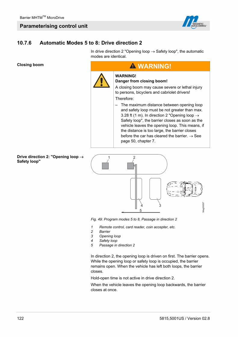
Barrier MHTMTM MicroDrive
Parameterising control unit
122 5815,5001US / Version 02.8
10.7.6 Automatic Modes 5 to 8: Drive direction 2
In drive direction 2 "Opening loop Safety loop", the automatic modes are identical.
Closing boom
WARNING!
WARNING! Danger from closing boom!
A closing boom may cause severe or lethal injury to persons, bicyclers and cabriolet drivers!
Therefore:
– The maximum distance between opening loop and safety loop must be not greater than max. 3.28 ft (1 m). In direction 2 "Opening loop Safety loop", the barrier closes as soon as the vehicle leaves the opening loop. This means, if the distance is too large, the barrier closes before the car has cleared the barrier. See page 50, chapter 7.
Drive direction 2: "Opening loop Safety loop"
Ma
g0
00
97
1 2
34
5
Fig. 49: Program modes 5 to 8, Passage in direction 2
1 Remote control, card reader, coin accepter, etc. 2 Barrier 3 Opening loop 4 Safety loop 5 Passage in direction 2
In direction 2, the opening loop is driven on first. The barrier opens. While the opening loop or safety loop is occupied, the barrier remains open. When the vehicle has left both loops, the barrier closes.
Hold-open time is not active in drive direction 2.
When the vehicle leaves the opening loop backwards, the barrier closes at once.

Barrier MHTMTM MicroDrive
Parameterising control unit
5815,5001US / Version 02.8 123
10.7.7 Mode "Service"
In the "Service" mode, all opening and closing signals are ignored. The functions of safety devices like the safety loop or safety light barrier remain active for security reasons. This means that as soon as, e.g., the safety loop is occupied, the barrier cannot be closed.
Switch on Mode "Service " Switch the "Service" switch for the "Service" mode. The LED lights red. The display backlighting flashes.
Switch off Mode "Service " After the service work, the switch "Service" must be switched. The LED must light green.
Mag00206b
2
1
Abb. 50: Service switch
1 Mode "Service" on 2 Mode "Service" off
Button function In the "Service" mode, you can control the motor with the two middle control buttons.
Middle left button : Manually open the barrier.
Middle right button : Manually close the barrier.
NOTE!
For reasons of safety, the first barrier arm motion after switching between program mode and service mode is performed at slow speed.
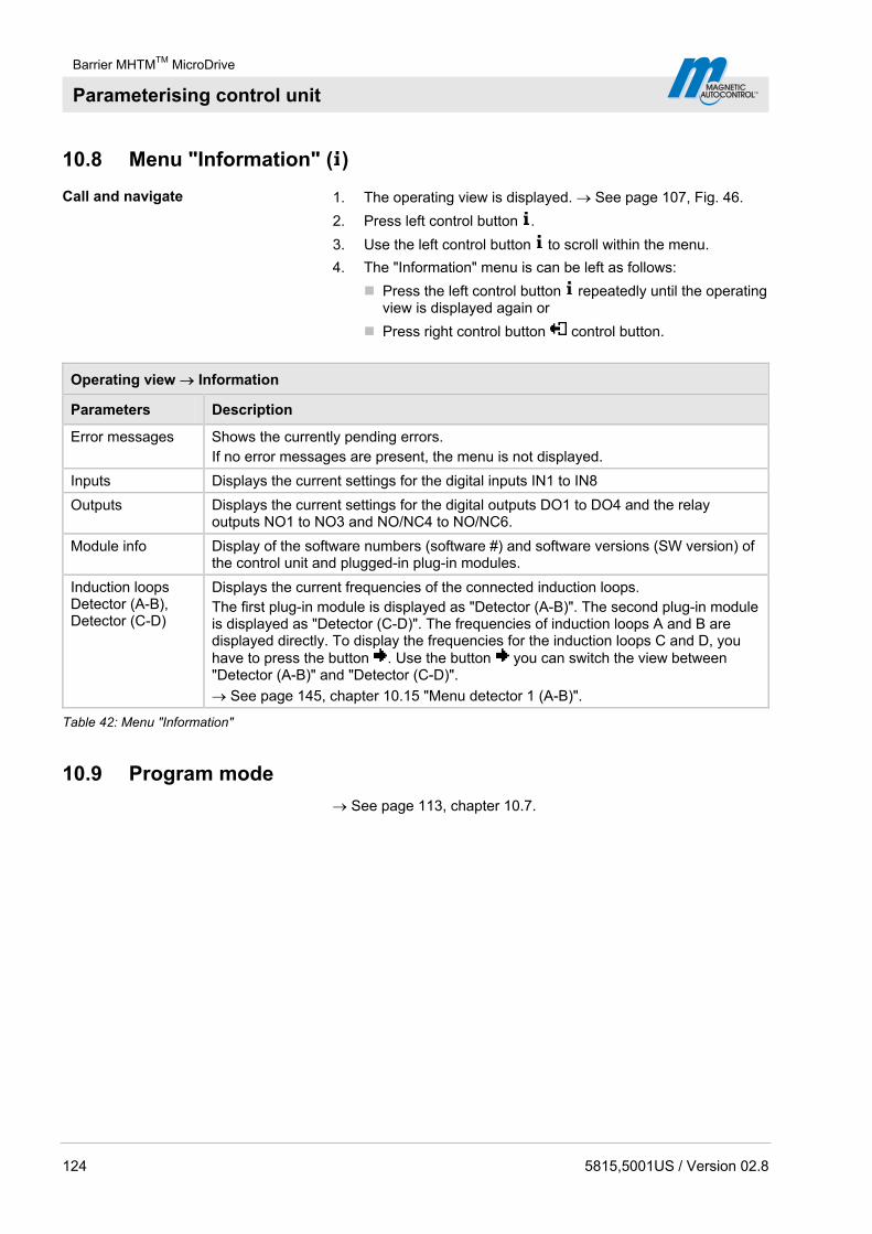
Barrier MHTMTM MicroDrive
Parameterising control unit
124 5815,5001US / Version 02.8
10.8 Menu "Information" ( )
Call and navigate 1. The operating view is displayed. See page 107, Fig. 46.
2. Press left control button .
3. Use the left control button to scroll within the menu.
4. The "Information" menu is can be left as follows:
Press the left control button repeatedly until the operating view is displayed again or
Press right control button control button.
Operating view Information
Parameters Description
Error messages Shows the currently pending errors. If no error messages are present, the menu is not displayed.
Inputs Displays the current settings for the digital inputs IN1 to IN8
Outputs Displays the current settings for the digital outputs DO1 to DO4 and the relay outputs NO1 to NO3 and NO/NC4 to NO/NC6.
Module info Display of the software numbers (software #) and software versions (SW version) of the control unit and plugged-in plug-in modules.
Induction loops Detector (A-B), Detector (C-D)
Displays the current frequencies of the connected induction loops. The first plug-in module is displayed as "Detector (A-B)". The second plug-in module is displayed as "Detector (C-D)". The frequencies of induction loops A and B are displayed directly. To display the frequencies for the induction loops C and D, you have to press the button . Use the button you can switch the view between "Detector (A-B)" and "Detector (C-D)".
See page 145, chapter 10.15 "Menu detector 1 (A-B)".
Table 42: Menu "Information"
10.9 Program mode
See page 113, chapter 10.7.
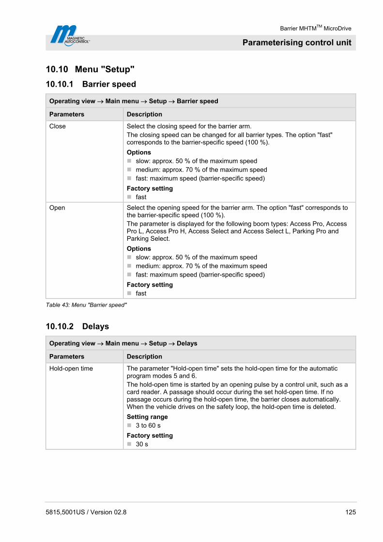
Barrier MHTMTM MicroDrive
Parameterising control unit
5815,5001US / Version 02.8 125
10.10 Menu "Setup"
10.10.1 Barrier speed
Operating view Main menu Setup Barrier speed
Parameters Description
Close Select the closing speed for the barrier arm. The closing speed can be changed for all barrier types. The option "fast" corresponds to the barrier-specific speed (100 %).
Options slow: approx. 50 % of the maximum speed medium: approx. 70 % of the maximum speed fast: maximum speed (barrier-specific speed)
Factory setting fast
Open Select the opening speed for the barrier arm. The option "fast" corresponds to the barrier-specific speed (100 %). The parameter is displayed for the following boom types: Access Pro, Access Pro L, Access Pro H, Access Select and Access Select L, Parking Pro and Parking Select.
Options slow: approx. 50 % of the maximum speed medium: approx. 70 % of the maximum speed fast: maximum speed (barrier-specific speed)
Factory setting fast
Table 43: Menu "Barrier speed"
10.10.2 Delays
Operating view Main menu Setup Delays
Parameters Description
Hold-open time The parameter "Hold-open time" sets the hold-open time for the automatic program modes 5 and 6. The hold-open time is started by an opening pulse by a control unit, such as a card reader. A passage should occur during the set hold-open time. If no passage occurs during the hold-open time, the barrier closes automatically. When the vehicle drives on the safety loop, the hold-open time is deleted.
Setting range 3 to 60 s
Factory setting 30 s

Barrier MHTMTM MicroDrive
Parameterising control unit
126 5815,5001US / Version 02.8
Operating view Main menu Setup Delays
Parameters Description
Close delay The barrier only closes if the set time for the closing delay is over. The timer for closing delay is started with the closing signal. With this parameter, you can also set the "Lead time" in the "Signal light" menu.
Setting range 0 to 15 s
Factory setting 0 s
Light barrier delay The barrier only closes if the set time for the light barrier delay is over. The timer for light barrier delay is started with clearance of the light barrier.
Setting range 0 to 15 s
Factory setting 5 s
Impact delay After the control unit has recognized that, e.g., a vehicle roof was hit by the closing barrier arm, the control unit tries to close the barrier again after the set impact delay. Impact is possible if, e.g., a user tries to drive through the barrier without permission. The following conditions must be met for the barrier to close after the end of the impact delay: In the "Impact Settings" menu, the parameter "Restart" must be set to
"Automatic". The safety devices, such as safety loop or safety light barrier, must be
clear.
Also see page 131, chapter 10.10.7, menu "Impact settings".
Setting range 5 to 30 s
Factory setting 5 s
Table 44: Menu "Delays"
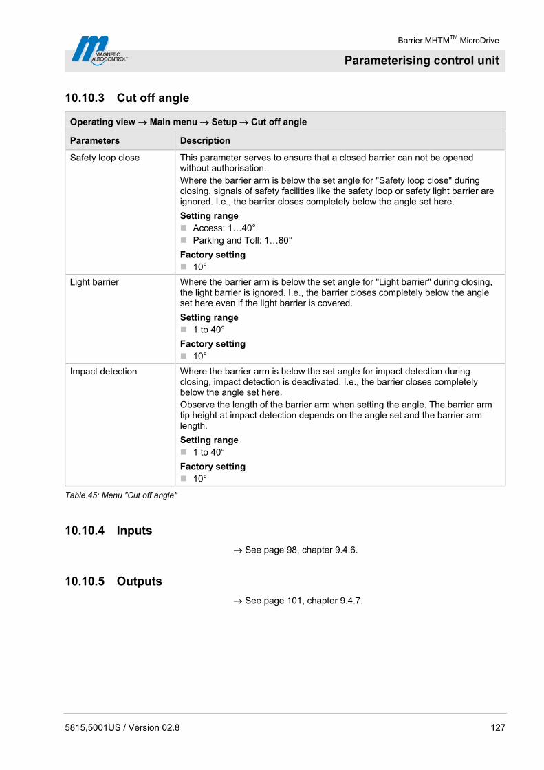
Barrier MHTMTM MicroDrive
Parameterising control unit
5815,5001US / Version 02.8 127
10.10.3 Cut off angle
Operating view Main menu Setup Cut off angle
Parameters Description
Safety loop close This parameter serves to ensure that a closed barrier can not be opened without authorisation. Where the barrier arm is below the set angle for "Safety loop close" during closing, signals of safety facilities like the safety loop or safety light barrier are ignored. I.e., the barrier closes completely below the angle set here.
Setting range Access: 1…40° Parking and Toll: 1…80°
Factory setting 10°
Light barrier Where the barrier arm is below the set angle for "Light barrier" during closing, the light barrier is ignored. I.e., the barrier closes completely below the angle set here even if the light barrier is covered.
Setting range 1 to 40°
Factory setting 10°
Impact detection Where the barrier arm is below the set angle for impact detection during closing, impact detection is deactivated. I.e., the barrier closes completely below the angle set here. Observe the length of the barrier arm when setting the angle. The barrier arm tip height at impact detection depends on the angle set and the barrier arm length.
Setting range 1 to 40°
Factory setting 10°
Table 45: Menu "Cut off angle"
10.10.4 Inputs
See page 98, chapter 9.4.6.
10.10.5 Outputs
See page 101, chapter 9.4.7.

Barrier MHTMTM MicroDrive
Parameterising control unit
128 5815,5001US / Version 02.8
10.10.6 Vend count
Operating view Main menu Setup Vend count
Parameters Description
Reset behaviour Use this parameter to set vend count reset behaviour. The function "Vend count" is available for program modes 4 to 8. An internal vend count counts the pulses present at the input with the "Opening with vend count" function. The pulses are decremented only in driving direction 1 "Safety loop Opening loop".
Options No counter reset (without vend count reset) Time-out
The vend count is set to the value "0" if the vehicle does not pass the supervision device within the set hold-open time.
Reset on closing The vend count is set to value "0" when a closing signal is given.
Time-out/Reset on closing The vend count is set to the value "0" if the event "Time-out" or the event "Reset on closing" occurs.
Factory setting Time-out/Reset on closing
Counter This parameter shows the current counter reading of the vend count.
Count open loop This function is sensible for systems where the opening loop is installed farther than one vehicle length away from the safety loop. When using this function, passage is permitted in one direction only. Once the function is activated, passages over the opening loop are counted as impulse. The direction is not considered when decrementing the impulses.
Options inactive active
Factory setting inactive
Table 46: Menu "Vend count"
Example vend count with program mode "Automatic mode (5)"
This mode is suitable for the automatic operation of a barrier, e.g. with card readers, remote control, coin accepters and induction loops or light barriers. The control units and the barrier have a larger distance from each other. Instead of a hold-open time, an internal vend count is incremented and decremented. Passage of the barrier is possible in either direction.
NOTE!
In systems where no opening loop is active or the parameter "Count open loops" is active, the impulses are decremented via the safety loop only.
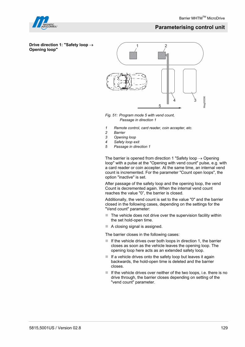
Barrier MHTMTM MicroDrive
Parameterising control unit
5815,5001US / Version 02.8 129
Drive direction 1: "Safety loop Opening loop"
Mag00096
1 2
34
5
Fig. 51: Program mode 5 with vend count, Passage in direction 1
1 Remote control, card reader, coin accepter, etc. 2 Barrier 3 Opening loop 4 Safety loop exit 5 Passage in direction 1
The barrier is opened from direction 1 "Safety loop Opening loop" with a pulse at the "Opening with vend count" pulse, e.g. with a card reader or coin accepter. At the same time, an internal vend count is incremented. For the parameter "Count open loops", the option "inactive" is set.
After passage of the safety loop and the opening loop, the vend Count is decremented again. When the internal vend count reaches the value "0”, the barrier is closed.
Additionally, the vend count is set to the value "0" and the barrier closed in the following cases, depending on the settings for the "Vend count" parameter:
The vehicle does not drive over the supervision facility within the set hold-open time.
A closing signal is assigned.
The barrier closes in the following cases:
If the vehicle drives over both loops in direction 1, the barrier closes as soon as the vehicle leaves the opening loop. The opening loop here acts as an extended safety loop.
If a vehicle drives onto the safety loop but leaves it again backwards, the hold-open time is deleted and the barrier closes.
If the vehicle drives over neither of the two loops, i.e. there is no drive through, the barrier closes depending on setting of the "vend count" parameter.
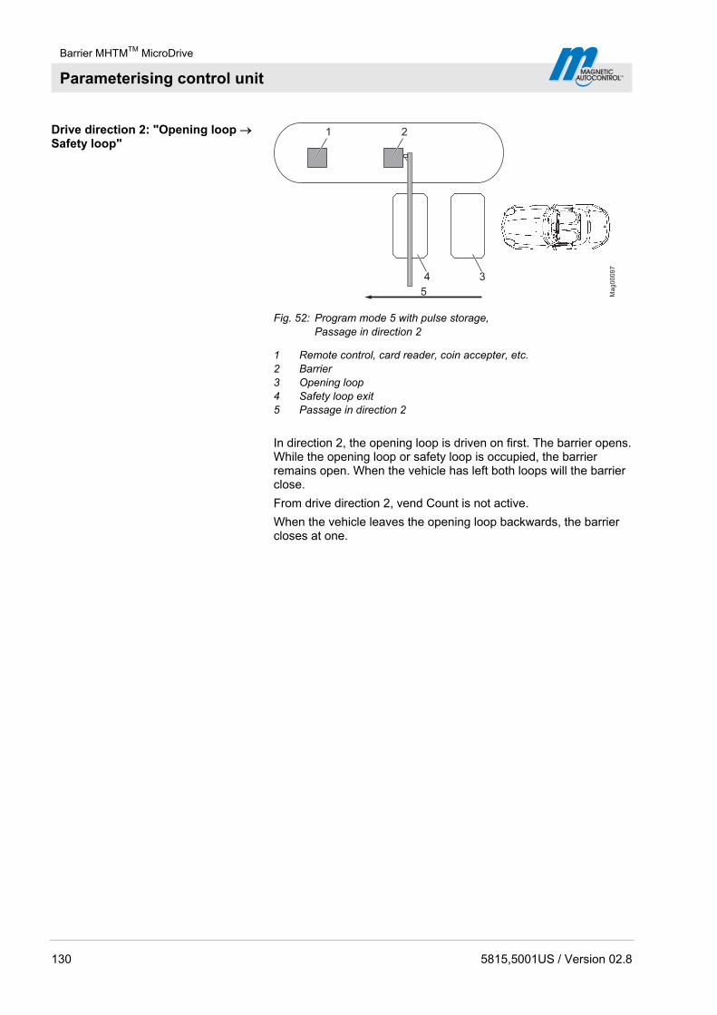
Barrier MHTMTM MicroDrive
Parameterising control unit
130 5815,5001US / Version 02.8
Drive direction 2: "Opening loop Safety loop"
Ma
g0
00
97
1 2
34
5
Fig. 52: Program mode 5 with pulse storage, Passage in direction 2
1 Remote control, card reader, coin accepter, etc. 2 Barrier 3 Opening loop 4 Safety loop exit 5 Passage in direction 2
In direction 2, the opening loop is driven on first. The barrier opens. While the opening loop or safety loop is occupied, the barrier remains open. When the vehicle has left both loops will the barrier close.
From drive direction 2, vend Count is not active.
When the vehicle leaves the opening loop backwards, the barrier closes at one.

Barrier MHTMTM MicroDrive
Parameterising control unit
5815,5001US / Version 02.8 131
10.10.7 Impact settings
Operating view Main menu Setup Impact settings
Parameters Description
Impact response Select the barrier arm's impact reaction if the control unit detects an impact. Also see page 127, chapter 10.10.3, parameter "Impact detection". Select the barrier boom's impact reaction if the control unit detects an impact. This setting relates to the impact detection while the barrier boom closes. If an impact is recognised during opening, the barrier boom is stopped.
Options Open
After impact detection, the barrier arm is opened completely. Stop
After impact detection, the barrier arm's closing movement is stopped. Safe stop
After impact detection, the barrier arm's closing movement is first stopped and then slightly opened.
Factory setting
Open
Impact delay After the control unit has recognized that, e.g., a vehicle roof was hit by the closing barrier arm, the control unit tries to close the barrier again after the set impact delay. Impact is possible if, e.g., a user tries to drive through the barrier without permission. The following conditions must be met for the barrier to close after the end of the impact delay: In the "Restart" parameter, the option must be set to "Automatic". The safety devices, such as safety loop or safety light barrier, must be
clear. This parameter corresponds to the parameter "Impact delay" in the "Delays" menu.
Setting range 5 to 30 s
Factory setting 5 s
Restart Select behaviour of the barrier after impact recognition.
Options Automatic
The barrier boom automatically completes the started movement after the impact delay has run.
Signal For the barrier boom to complete the started movement, the matching signal (open/close) must be applied.
Factory setting Signal
Table 47: Menu "Impact settings"

Barrier MHTMTM MicroDrive
Parameterising control unit
132 5815,5001US / Version 02.8
10.10.8 Start-up behaviour
Use this menu to select the start-up behaviour of the barrier according to the following events:
after switching on voltage supply
after return of voltage
after reset
You can select between 7 options: The default setting is option "1".
NOTE!
The display messages "Waiting for passage" and "Waiting for release" can be confirmed with the left button of the control unit. Ensure that no persons or vehicles are present below the barrier arm. In operating modes 3 to 8, the barrier will close as soon as the message has been confirmed. In operating modes 1 and 2, a closing signal is still required after the message is confirmed.
Operating view Main menu Settings Start-up behaviour (Start-up behav.)
Option Description
1 Reference run In this option, the barrier initially performs a reference run. This means that the barrier opens completely at low speed.
Release signal No release signal is required to close the boom.
Closing behaviour Program modes 1 or 2:
If a safety loop is installed, the barrier closes only after a vehicle has passed through and a permanent closing signal is pending. If only a safety light barrier is installed, no passage is required. The barrier closes at once when a permanent closing signal is applied.
Program modes 3 to 8: If a safety loop is installed, the barrier closes when the first vehicle has driven through. If only a safety light barrier is installed, the barrier closes at once when the voltage returns.
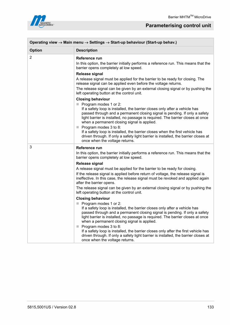
Barrier MHTMTM MicroDrive
Parameterising control unit
5815,5001US / Version 02.8 133
Operating view Main menu Settings Start-up behaviour (Start-up behav.)
Option Description
2 Reference run In this option, the barrier initially performs a reference run. This means that the barrier opens completely at low speed.
Release signal A release signal must be applied for the barrier to be ready for closing. The release signal can be applied even before the voltage returns. The release signal can be given by an external closing signal or by pushing the left operating button at the control unit.
Closing behaviour Program modes 1 or 2:
If a safety loop is installed, the barrier closes only after a vehicle has passed through and a permanent closing signal is pending. If only a safety light barrier is installed, no passage is required. The barrier closes at once when a permanent closing signal is applied.
Program modes 3 to 8: If a safety loop is installed, the barrier closes when the first vehicle has driven through. If only a safety light barrier is installed, the barrier closes at once when the voltage returns.
3 Reference run In this option, the barrier initially performs a reference run. This means that the barrier opens completely at low speed.
Release signal A release signal must be applied for the barrier to be ready for closing. If the release signal is applied before return of voltage, the release signal is ineffective. In this case, the release signal must be revoked and applied again after the barrier opens. The release signal can be given by an external closing signal or by pushing the left operating button at the control unit.
Closing behaviour Program modes 1 or 2:
If a safety loop is installed, the barrier closes only after a vehicle has passed through and a permanent closing signal is pending. If only a safety light barrier is installed, no passage is required. The barrier closes at once when a permanent closing signal is applied.
Program modes 3 to 8: If a safety loop is installed, the barrier closes only after the first vehicle has driven through. If only a safety light barrier is installed, the barrier closes at once when the voltage returns.
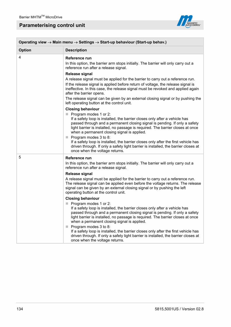
Barrier MHTMTM MicroDrive
Parameterising control unit
134 5815,5001US / Version 02.8
Operating view Main menu Settings Start-up behaviour (Start-up behav.)
Option Description
4 Reference run In this option, the barrier arm stops initially. The barrier will only carry out a reference run after a release signal.
Release signal A release signal must be applied for the barrier to carry out a reference run. If the release signal is applied before return of voltage, the release signal is ineffective. In this case, the release signal must be revoked and applied again after the barrier opens. The release signal can be given by an external closing signal or by pushing the left operating button at the control unit.
Closing behaviour Program modes 1 or 2:
If a safety loop is installed, the barrier closes only after a vehicle has passed through and a permanent closing signal is pending. If only a safety light barrier is installed, no passage is required. The barrier closes at once when a permanent closing signal is applied.
Program modes 3 to 8: If a safety loop is installed, the barrier closes only after the first vehicle has driven through. If only a safety light barrier is installed, the barrier closes at once when the voltage returns.
5 Reference run In this option, the barrier arm stops initially. The barrier will only carry out a reference run after a release signal.
Release signal A release signal must be applied for the barrier to carry out a reference run. The release signal can be applied even before the voltage returns. The release signal can be given by an external closing signal or by pushing the left operating button at the control unit.
Closing behaviour Program modes 1 or 2:
If a safety loop is installed, the barrier closes only after a vehicle has passed through and a permanent closing signal is pending. If only a safety light barrier is installed, no passage is required. The barrier closes at once when a permanent closing signal is applied.
Program modes 3 to 8: If a safety loop is installed, the barrier closes only after the first vehicle has driven through. If only a safety light barrier is installed, the barrier closes at once when the voltage returns.
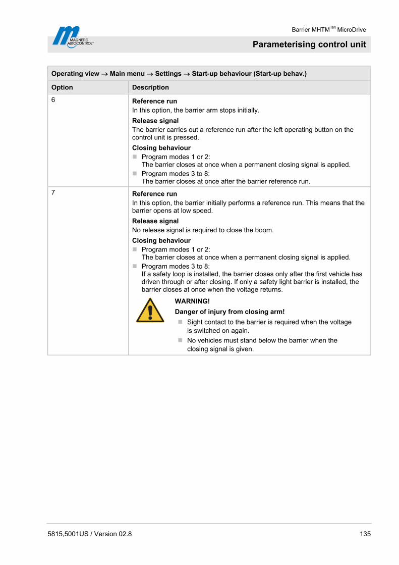
Barrier MHTMTM MicroDrive
Parameterising control unit
5815,5001US / Version 02.8 135
Operating view Main menu Settings Start-up behaviour (Start-up behav.)
Option Description
6 Reference run In this option, the barrier arm stops initially.
Release signal The barrier carries out a reference run after the left operating button on the control unit is pressed.
Closing behaviour Program modes 1 or 2:
The barrier closes at once when a permanent closing signal is applied. Program modes 3 to 8:
The barrier closes at once after the barrier reference run.
7 Reference run In this option, the barrier initially performs a reference run. This means that the barrier opens at low speed.
Release signal No release signal is required to close the boom.
Closing behaviour Program modes 1 or 2:
The barrier closes at once when a permanent closing signal is applied. Program modes 3 to 8:
If a safety loop is installed, the barrier closes only after the first vehicle has driven through or after closing. If only a safety light barrier is installed, the barrier closes at once when the voltage returns.
WARNING!
Danger of injury from closing arm!
Sight contact to the barrier is required when the voltage is switched on again.
No vehicles must stand below the barrier when the closing signal is given.

Barrier MHTMTM MicroDrive
Parameterising control unit
136 5815,5001US / Version 02.8
Operating view Main menu Settings Start-up behaviour (Start-up behav.)
Option Description
8 Reference run In this option, the barrier initially performs a reference run. This means that the barrier opens at low speed.
Release signal No release signal is required to close the boom.
Closing behaviour Program modes 1 or 2:
The barrier closes at once when a permanent closing signal is applied. Program modes 3 to 8:
Barrier closes at once.
WARNING!
Danger of injury from closing arm!
Sight contact to the barrier is required when the voltage is switched on again.
No vehicles must stand below the barrier when the closing signal is given.
Table 48: Menu "Start-up behaviour"

Barrier MHTMTM MicroDrive
Parameterising control unit
5815,5001US / Version 02.8 137
10.10.9 Power failure
Operating view Main menu Setup Power failure
Parameters Description
Power failure This parameter sets whether the barrier arm opens at power outage or opens or closes depending on the barrier arm position. The balancing springs must be set according to the selected option. See page 81, chapter 8.13.
Options Unlocked
With this option, the lever system of the closed barrier is unlocked; the barrier remains closed. The boom can be opened manually. If the boom angle is less than approx. 30°, the boom will close. If the barrier arm is above an angle of approx. 35°, the barrier arm opens. The ba-lancing springs in the lever system must be set accordingly.
Open In this option, the barrier arm opens at power outage. The barrier arm is moved to the locked end position with the present residual energy of the mains unit and completely opened by the balancer springs of the lever system. The balancing springs must be set correctly and the barrier arm must not be kept in the closed position by external influence.
Locked For this option, the barrier arm behaviour depends on the barrier arm position at power outage. When the barrier is closed, it remains closed and the lever system remains locked. Manual opening of the barrier is not possible or requires considerable application of force. If the barrier arm is below an angle of approx. 30°, the barrier arm closes. If the barrier arm is above an angle of approx. 35°, the barrier arm opens. The balancing springs in the lever system must be set accordingly.
Factory setting Unlocked
Table 49: Menu "Power failure"

Barrier MHTMTM MicroDrive
Parameterising control unit
138 5815,5001US / Version 02.8
10.10.10 Closure by light barrier
Operating view Main menu Settings Closure by light barrier (light barr.)
Parameters Description
Closure by light barrier Use this parameter to select the closing behaviour for barriers with only one safety light barrier installed. If a safety loop is installed, the barrier closes only after the first vehicle has driven through in the automatic program modes 5 to 8. If only a safety light barrier is installed, the barrier will not close automatically after the first vehicle has driven through in the automatic program modes 5 to 8.
Options Inactive
In program modes 5 and 6, the barrier only closes if either a closing signal is applied or the hold-open time has passed. In program modes 7 and 8, the barrier only closes when a closing signal is applied.
Active In program modes 5 to 8, the barrier closes at once when a vehicle drives through the safety light barrier and after passage of the set time for the parameter "Light barrier delay". See page 126, chapter 10.10.2.
Factory setting Inactive
Table 50: Menu "Closure by light barrier"
10.10.11 Master/Slave
Operating view Main Menu Settings Master/Slave
Parameters Description
Master/Slave Activate and deactivate "Parallel operation" function. By activating the master/slave function, the corresponding inputs and outputs are automatically converted. For information on parallel operation, see separate instructions.
Options inactive active
Factory setting inactive
Table 51: Menu “Master/Slave”

Barrier MHTMTM MicroDrive
Parameterising control unit
5815,5001US / Version 02.8 139
10.11 Menu "Attachments"
10.11.1 Signal light
The parameters "Signal mode A", "Signal mode B" and "Signal mode C" can be used to parameterise the function for the outputs "Signal light A", "Signal light B" and "Signal light C". See page 101, Table 29.
You can connect three signal lights.
If you want to control light strips via the MAGNETIC control unit, you need to select the "Illumination strip red" option for "Signal Mode A" and "Illumination strip green" for "Signal Mode B".
Operating view Main menu Attachments Signal light
Parameters Description
Signal mode A (continued on next page)
Select function for output "Signal light A".
The parameter "lead time" can be used to parameterise the warning lamp so that it already lights up red or flashes before closing. The lead time is the time between the closing signal and commencement of the closing procedure.
Options Traffic light (permanent signal for red/green signal lights): Barrier closed: Traffic light red Barrier opens: Traffic light red Barrier open (upper end position): Traffic light off Barrier closes (without lead time)/
closing time (with lead time): Traffic light red Warning signal (connection of a visual or acoustic signal/
permanent signal before and during closing of the barrier): Barrier closed: Warning signal off Barrier opens: Warning signal off Barrier open (upper end position): Warning signal off Barrier closes (without lead time)/
closing time (with lead time): Warning signal red Flashing light (flashing light connection/
flashing signal while the barrier opens or closes): Barrier closed: Flashing light off Barrier opens: Flashing light flashes at 2 Hz Barrier open (upper end position): Flashing light off Barrier closes (without lead time)/
closing time (with lead time): Flashing light flashes at 2 Hz Boom illumination (boom illumination connection/
permanent flashing signal except when the barrier is open): Barrier closed: Illumination flashes at 2 Hz Barrier opens: Illumination flashes at 2 Hz Barrier open (upper end position): Illumination off Barrier closes (without lead time)/
closing time (with lead time): Illumination flashes at 2 Hz

Barrier MHTMTM MicroDrive
Parameterising control unit
140 5815,5001US / Version 02.8
Operating view Main menu Attachments Signal light
Parameters Description
Signal mode A (continued)
Illumination strip red / Boom illumination / Flashing light
Barrier closed (lower end position): Red, permanent light Barrier opens: Red flashes at 2 Hz Barrier open (upper end position): Red off Barrier closes (without lead time)/
closing time (with lead time): Red flashes at 2 Hz
Factory setting Illumination strip red
Signal mode B Select function for output "Signal light B".
Options
For the options "Traffic light", "Warning signal", "Flashing lights", "Boom illumination", see parameters "signal mode A".
Illumination strip green
Barrier closed (lower end position): Green off Barrier opens: Green off Barrier open (upper end position): Green, permanent light Barrier closes (without lead time)/
closing time (with lead time): Green off
Factory setting Illumination strip green
Signal mode C Select function for output "Signal light C".
Options Traffic light (permanent signal for red/green signal lights): Barrier closed: Traffic light red Barrier opens: Traffic light red Barrier open (upper end position): Traffic light off Barrier closes (without lead time)/
closing time (with lead time): Traffic light red
Warning signal (connection of a visual or acoustic signal/ permanent signal before and during closing of the barrier): Barrier closed: Warning signal off Barrier opens: Warning signal off Barrier open (upper end position): Warning signal off Barrier closes (without lead time)/
closing time (with lead time): Warning signal red
Factory setting Warning signal
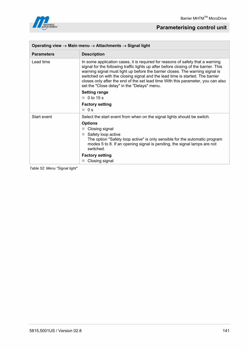
Barrier MHTMTM MicroDrive
Parameterising control unit
5815,5001US / Version 02.8 141
Operating view Main menu Attachments Signal light
Parameters Description
Lead time In some application cases, it is required for reasons of safety that a warning signal for the following traffic lights up after before closing of the barrier. This warning signal must light up before the barrier closes. The warning signal is switched on with the closing signal and the lead time is started. The barrier closes only after the end of the set lead time With this parameter, you can also set the "Close delay" in the "Delays" menu.
Setting range 0 to 15 s
Factory setting 0 s
Start event Select the start event from when on the signal lights should be switch.
Options Closing signal Safety loop active
The option "Safety loop active" is only sensible for the automatic program modes 5 to 8. If an opening signal is pending, the signal lamps are not switched.
Factory setting Closing signal
Table 52: Menu "Signal light"
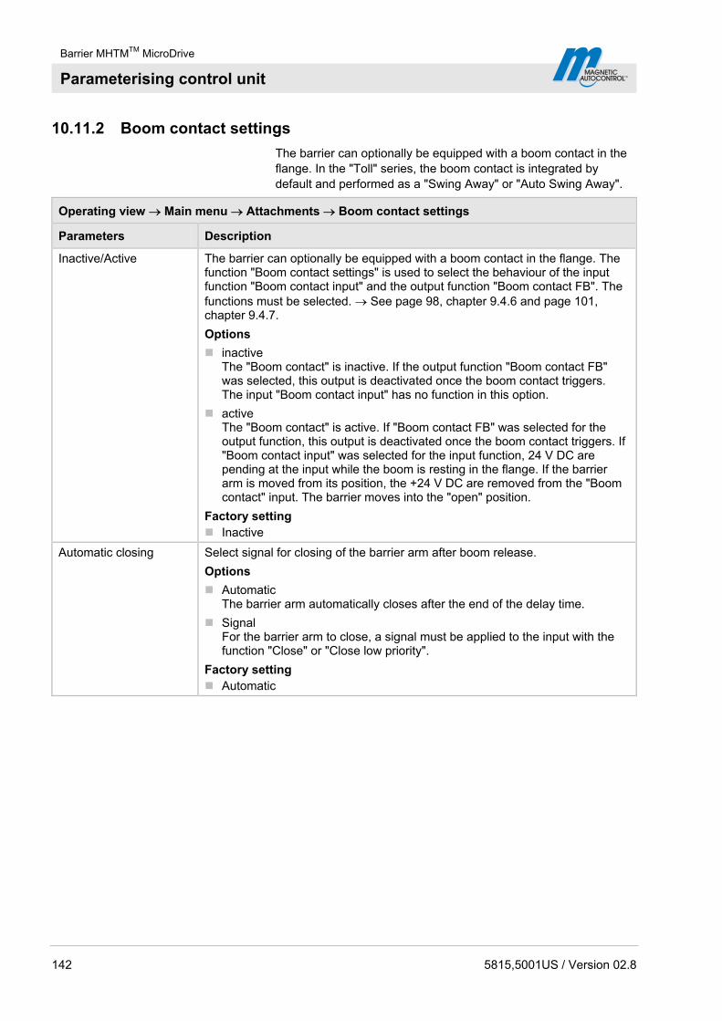
Barrier MHTMTM MicroDrive
Parameterising control unit
142 5815,5001US / Version 02.8
10.11.2 Boom contact settings
The barrier can optionally be equipped with a boom contact in the flange. In the "Toll" series, the boom contact is integrated by default and performed as a "Swing Away" or "Auto Swing Away".
Operating view Main menu Attachments Boom contact settings
Parameters Description
Inactive/Active The barrier can optionally be equipped with a boom contact in the flange. The function "Boom contact settings" is used to select the behaviour of the input function "Boom contact input" and the output function "Boom contact FB". The functions must be selected. See page 98, chapter 9.4.6 and page 101, chapter 9.4.7.
Options
inactive The "Boom contact" is inactive. If the output function "Boom contact FB" was selected, this output is deactivated once the boom contact triggers. The input "Boom contact input" has no function in this option.
active The "Boom contact" is active. If "Boom contact FB" was selected for the output function, this output is deactivated once the boom contact triggers. If "Boom contact input" was selected for the input function, 24 V DC are pending at the input while the boom is resting in the flange. If the barrier arm is moved from its position, the +24 V DC are removed from the "Boom contact" input. The barrier moves into the "open" position.
Factory setting Inactive
Automatic closing Select signal for closing of the barrier arm after boom release.
Options
Automatic The barrier arm automatically closes after the end of the delay time.
Signal For the barrier arm to close, a signal must be applied to the input with the function "Close" or "Close low priority".
Factory setting Automatic

Barrier MHTMTM MicroDrive
Parameterising control unit
5815,5001US / Version 02.8 143
Operating view Main menu Attachments Boom contact settings
Parameters Description
Closing delay The parameters are only relevant in the following cases: The barrier is a "Swing Away" or "Auto Swing Away" design. In the "Close autom." parameter, the option is set to "Automatic". If a car drives against a "Swing Away" barrier arm, it snaps from the flange. In the "Swing Away" version, the barrier arm must be returned to the flange manually. In the "Auto Swing Away" version, the barrier arm automatically moves into the "open" position. When the position is reached, the barrier arm is locked in the flange by springs. After the barrier arm has caught again, the barrier closes after the time set here.
Setting range 0 to 10 s
Factory setting 10 s
Table 53: Menu "Boom contact settings"
10.11.3 Boom locking
The barrier can optionally be equipped with an electro-mechanical boom lock at the end of the barrier arm. When the barrier is closed, the boom locking is activated via the output function "Boom locking". If a signal is present for opening, the boom lock is released first. Refer also to page 101, digital output function "Boom locking".
Operating view Main menu Attachments Boom locking
Parameters Description
Without boom locking Boom locking not present.
With boom locking Boom locking present.
Table 54: Menu "Boom locking"
10.12 Menu "Service"
This menu is only intended for MAGNETIC's service and only accessible with a password.
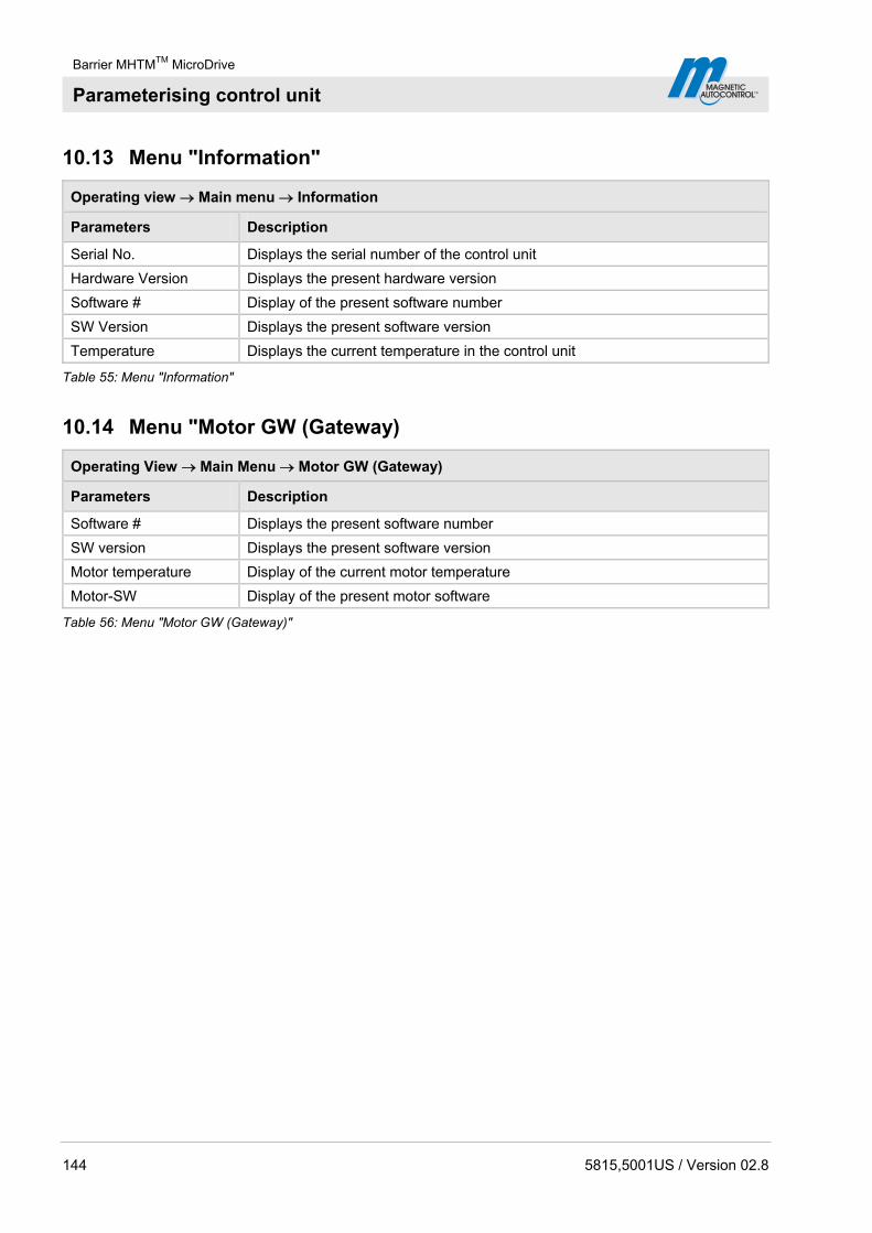
Barrier MHTMTM MicroDrive
Parameterising control unit
144 5815,5001US / Version 02.8
10.13 Menu "Information"
Operating view Main menu Information
Parameters Description
Serial No. Displays the serial number of the control unit
Hardware Version Displays the present hardware version
Software # Display of the present software number
SW Version Displays the present software version
Temperature Displays the current temperature in the control unit
Table 55: Menu "Information"
10.14 Menu "Motor GW (Gateway)
Operating View Main Menu Motor GW (Gateway)
Parameters Description
Software # Displays the present software number
SW version Displays the present software version
Motor temperature Display of the current motor temperature
Motor-SW Display of the present motor software
Table 56: Menu "Motor GW (Gateway)"
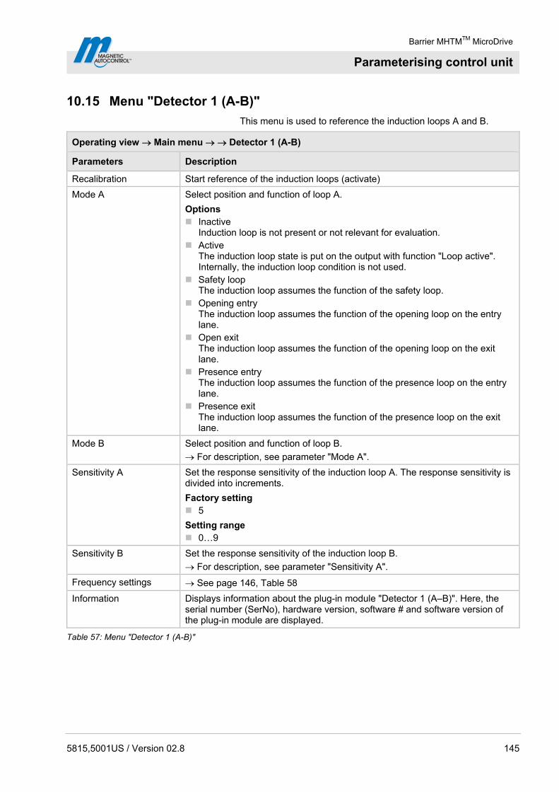
Barrier MHTMTM MicroDrive
Parameterising control unit
5815,5001US / Version 02.8 145
10.15 Menu "Detector 1 (A-B)"
This menu is used to reference the induction loops A and B.
Operating view Main menu Detector 1 (A-B)
Parameters Description
Recalibration Start reference of the induction loops (activate)
Mode A Select position and function of loop A.
Options Inactive
Induction loop is not present or not relevant for evaluation. Active
The induction loop state is put on the output with function "Loop active". Internally, the induction loop condition is not used.
Safety loop The induction loop assumes the function of the safety loop.
Opening entry The induction loop assumes the function of the opening loop on the entry lane.
Open exit The induction loop assumes the function of the opening loop on the exit lane.
Presence entry The induction loop assumes the function of the presence loop on the entry lane.
Presence exit The induction loop assumes the function of the presence loop on the exit lane.
Mode B Select position and function of loop B.
For description, see parameter "Mode A".
Sensitivity A Set the response sensitivity of the induction loop A. The response sensitivity is divided into increments.
Factory setting 5
Setting range 0…9
Sensitivity B Set the response sensitivity of the induction loop B.
For description, see parameter "Sensitivity A".
Frequency settings See page 146, Table 58
Information Displays information about the plug-in module "Detector 1 (A–B)". Here, the serial number (SerNo), hardware version, software # and software version of the plug-in module are displayed.
Table 57: Menu "Detector 1 (A-B)"
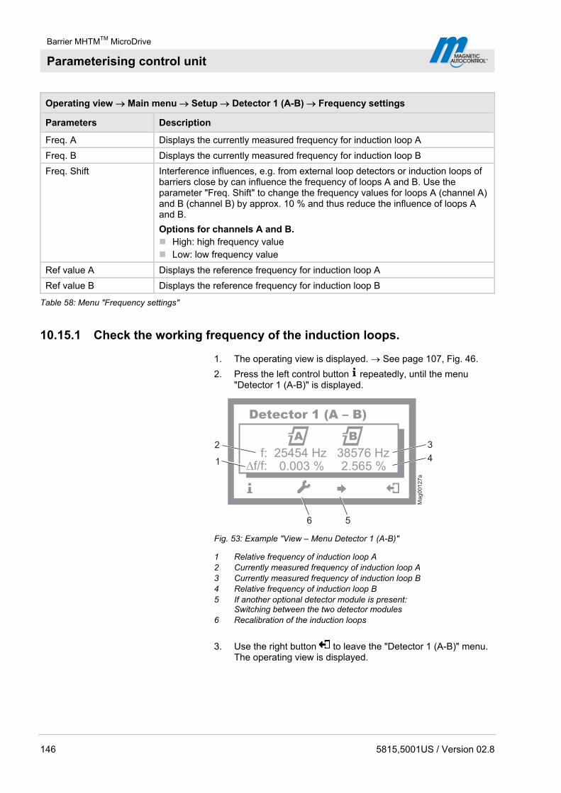
Barrier MHTMTM MicroDrive
Parameterising control unit
146 5815,5001US / Version 02.8
Operating view Main menu Setup Detector 1 (A-B) Frequency settings
Parameters Description
Freq. A Displays the currently measured frequency for induction loop A
Freq. B Displays the currently measured frequency for induction loop B
Freq. Shift Interference influences, e.g. from external loop detectors or induction loops of barriers close by can influence the frequency of loops A and B. Use the parameter "Freq. Shift" to change the frequency values for loops A (channel A) and B (channel B) by approx. 10 % and thus reduce the influence of loops A and B.
Options for channels A and B. High: high frequency value Low: low frequency value
Ref value A Displays the reference frequency for induction loop A
Ref value B Displays the reference frequency for induction loop B
Table 58: Menu "Frequency settings"
10.15.1 Check the working frequency of the induction loops.
1. The operating view is displayed. See page 107, Fig. 46.
2. Press the left control button repeatedly, until the menu "Detector 1 (A-B)" is displayed.
Ma
g0
01
27
a
f: 25454 Hz 38576 Hz�f/f: 0.003 % 2.565 %
A B
56
1
2 3
4
Detector 1 (A – B)
Fig. 53: Example "View – Menu Detector 1 (A-B)"
1 Relative frequency of induction loop A 2 Currently measured frequency of induction loop A 3 Currently measured frequency of induction loop B 4 Relative frequency of induction loop B 5 If another optional detector module is present:
Switching between the two detector modules 6 Recalibration of the induction loops
3. Use the right button to leave the "Detector 1 (A-B)" menu. The operating view is displayed.
Barrier MHTMTM MicroDrive
Parameterising control unit
5815,5001US / Version 02.8 147
10.15.2 Reconciling and setting the operating frequency of the induction loop
Operating frequency requirements The operating frequency must fulfil following requirements:
When driving over the induction loop with a vehicle, a significant frequency increase must be measurable. Chose stage 5 or 6 for sensitivity. The relative frequency change (f/f) must be at least 0.1%. The higher the relative frequency increase, the higher the operating safety of the induction loop.
The induction loops of a control unit operate alternating, and can therefore not affect each other. However, to avoid interferences by frequency coupling from external loop detectors or other control units in the direct proximity, a frequency clearance of at least 10000 Hz must be kept between them. For this, the menu "Freq. Shift" is used to set the frequency option to "Low" or "High", or to deactivate or adjust the induction loop windings number.
Reference working frequency via the menu “Information" ( )
1. The operating view is displayed. See page 107, Fig. 46.
2. Press left operating button .
3. Press the left control button repeatedly, until the menu "Detector 1 (A-B)" is displayed. See page 146, Fig. 53.
4. Press second operating button from the left .
5. The barrier is referenced. The loop symbols flash during reconciliation.
6. Check working frequencies. If required, perform settings like sensitivity, etc. in the menu "Detector 1 (A-B)" in the main menu.
7. Perform one of the following steps:
For a "Detector" plug-in module: Use the right button to leave the "Detector 1 (A-B)" menu. The operating view is displayed.
For two "Detector" plug-in modules: Press the third opera-ting button from the left . The "Detector 2 (C-D)" menu is displayed.
8. The barrier is referenced. The loop symbols flash during reconciliation.
9. Check working frequencies. If required, perform settings like sensitivity, etc. in the menu "Detector 2 (C-D)" in the main menu.
10. Use the right button to leave the "Detector 2 (C-D)" menu. The operating view is displayed.

Barrier MHTMTM MicroDrive
Parameterising control unit
148 5815,5001US / Version 02.8
Frequency value of the un-assigned induction loop unstable
If the frequency value of an induction loop is unstable, this induction loop is influenced by an induction loop of another barrier or an external detector. The detector channels do not influence each other.
Depending on the loop geometry and settings of the external detector, set the menu "Freq. Shift" to "Low" or "High".
1. The operating view is displayed. See page 107, Fig. 46.
2. Press right operating button .
3. The "Main menu" menu is displayed.
4. Select the menu "Detector 1 (A-B)" with the two middle buttons , .
5. Confirm selection with the right control button .
6. The "Detector 1 (A-B)" menu is displayed.
7. Select the menu "Frequency settings" with the two middle buttons , .
8. Confirm selection with the right control button .
9. The "Frequency settings" menu is displayed.
10. Select the menu "Freq. Shift" with the two middle buttons , .
11. Confirm selection with the right control button .
12. The "Freq. Shift" menu is displayed.
13. Select the parameter "Channel A" or "Channel B" with the two middle buttons , .
14. Confirm selection with the right control button .
15. The corresponding menu is displayed.
16. Select the option "Low" or "High" for the respective channel with the two middle buttons , .
17. Use the right button to select the option. Your selection is marked with the symbol .
18. Use the left button to leave the menu.
19. The safety prompt "Save changes?" appears.
If the changes are to be saved, press the right button .
If the changes are not to be saved, press the left button .
20. Press the left button repeatedly until the operating view is displayed again.
21. Test the operating frequencies.
For another plug-in module, the menu "Detector 2 (C-D)" is displayed in the main menu. Reconciliation is performed for the induction loops A and B.

Barrier MHTMTM MicroDrive
Parameterising control unit
5815,5001US / Version 02.8 149
10.16 Menu "Detector 2 (C-D)"
This menu is displayed if a second plug-in module with the function "Detector" was plugged into the control unit. This menu is used to reference the induction loops C and D.
The menu "Detector 2 (C-D)" corresponds to the menu "Detector 1 (A-D)". See page 145, chapter 10.16.
10.17 Menu "Radio control"
The "Radio control" menu is displayed when the "radio" plug-in module is plugged into one of the control unit slots.
The hand transmitters are available as 1-, 2- and 4-channel versions. With the multi-channel version, the corresponding number of barriers can be operated independently of each other with a hand transmitter.
If you want to operate the barrier via hand transmitter, manual program mode 3 or one of the automated program modes 5 to 8 must be selected.
The barrier is opened by pressing the button on the hand transmitter. The closing function depends on the selected program mode. In automatic modes 5 to 8, the barrier is closed automatically. In program mode 3, the barrier is closed by repeated pressing of the button on the hand transmitter. After pressing the button on the hand transmitter, the hand transmitter number is indicated in the display.
A radio module can manage up to 100 hand transmitters using different codes.
Operating view Main menu Radio control
Parameters Description
Number of transm. (Number of transmitter)
Display of number of hand transmitters with which the barrier can be opened
Teach in remote control Use this parameter to pair a hand transmitter with the radio module.
Options Open high priority
The button is assigned to the function "Open high priority". Open
The button is assigned to the function "Opening". Close
The button is assigned to the function "Closing".

Barrier MHTMTM MicroDrive
Parameterising control unit
150 5815,5001US / Version 02.8
Operating view Main menu Radio control
Parameters Description
Delete remote control Use this parameter to revoke a pairing between a hand transmitter and the radio module.
Options With remote control
Dissolve pairing by pressing a button on the hand transmitter. With number
Dissolve pairing by entering the hand transmitter number. Delete ALL
Delete all hand transmitters. Password input is required for this.
Information Displays information about the plug-in module "Radio". Here, the hardware version, software version and serial number (SerNo) of the plug-in module are displayed.
Table 59: Menu "Radio control"
Set hand transmitter code The hand transmitter code is set via DIP switches in the hand transmitter. We recommend changing the DIP switches' standard settings.
1. Open hand transmitter housing. For this, press the coloured pressure point while pulling up the upper housing part at the same time.
2. Change and document the DIP switches' settings.
5 6 7 9
OFF
1 2 3 4 Mag00210
ON
108 11 12
Fig. 54: Example DIP switches settings
3. Close housing.
Barrier MHTMTM MicroDrive
Parameterising control unit
5815,5001US / Version 02.8 151
Teach in remote control example option "Close"
1. The operating view is displayed. See page 107, Fig. 46.
2. Press right operating button .
3. The "Main menu" menu is displayed.
4. Select the menu "Radio control" with the two middle buttons , .
5. Confirm selection with the right control button .
6. Select the parameter "Teach in remote control" with the two middle buttons , .
7. Confirm selection with the right control button .
8. Select the parameter "Close" with the two middle buttons , .
9. The message "Press button" appears.
10. Press the button on the hand transmitter. For the 2-channel hand transmitter, the corresponding channel is paired with the radio module.
11. The message "Successful" appears on the display. The number for the parameter "Number of transmitter" is increased by one.
12. Press the left button repeatedly until the operating view is displayed again.
Delete remote control 1. The operating view is displayed. See page 107, Fig. 46.
2. Press right operating button .
3. The "Main menu" menu is displayed.
4. Select the menu "Radio control FM" with the two middle buttons , .
5. Confirm selection with the right control button .
6. Select the parameter "delete remote control" with the two middle buttons , .
7. Confirm selection with the right control button .
8. The options "With remote control" and "With number" are displayed.
9. Select an option with the two middle buttons , .
10. Confirm selection with the right control button .
Option "with remote control" The option "With remote control" was selected
1. The message "press button" appears.
2. Press the button on the hand transmitter.
3. The message "Successful" appears. The number for the parameter "Number transmitter" is decreased by one.
4. Press the left button repeatedly until the operating view is displayed again.
Barrier MHTMTM MicroDrive
Parameterising control unit
152 5815,5001US / Version 02.8
Option "with number" The option "With number" was selected
1. Enter hand transmitter number.
2. Use the left button to leave the menu.
3. The safety prompt "Save changes?" appears.
If the hand transmitter is to be deleted, press the right button .
If the hand transmitter is to be deleted, press the left button .
4. The "Delete remote control" menu is displayed.
5. Press the left button repeatedly until the operating view is displayed again.
Option "Delete ALL" The option "Delete ALL" was selected
1. Enter the service password.
2. Confirm input with the right control button .
3. The message "Successful" appears. All hand transmitters were deleted.
NOTE!
If a hand transmitter is deleted, the memory slot used is released. The sequence does not change by deletion. Teaching in new hand transmitters will first fill the gaps and only then continue numbering.

Barrier MHTMTM MicroDrive
Parameterising control unit
5815,5001US / Version 02.8 153
10.18 Factory Settings
Reset parameters This menu can be used to reset the parameters to factory settings.
1. The operating view is displayed. See page 107, Fig. 46
2. Press right operating button .
3. The "Main menu" menu is displayed.
4. Select the menu "Factory Settings" with the two middle buttons , .
5. Confirm selection with the right control button .
6. Enter password "0 0 0 0".
7. Confirm password with the right control button .
8. The message "Reset to factory settings” appears.
9. Press right operating button .
10. The safety prompt "Save changes?" appears.
If the changes are to be saved, press the right button . The current settings are reset to factory settings. Restart is performed
If the changes are not to be saved, press the left button .
11. Press the left button repeatedly until the operating view is displayed again.

Barrier MHTMTM MicroDrive
Start-up and operation
154 5815,5001US / Version 02.8
11 Start-up and operation
11.1 Safety
See also safety notes on page 20, chapter 2.6 "Occupational safety and special dangers".
General
WARNING!
WARNING! Danger by inappropriate start-up and operation!
Inappropriate start-up and operation can cause severe or lethal injuries.
Therefore:
– Commissioning and operation must be performed by specialists or electronics specialists.
– Always observe the radius of action of the barrier arm.
– Prior to start of works ensure that all housing covers are correctly mounted.
Wind forces over 10 Beaufort
WARNING!
WARNING! Risk of injury from breaking off barrier arms in case of high wind speeds!
In case of wind speeds exceeding 10 Beaufort, the barrier arm may break off from the wind load and cause severe injuries.
Therefore observe in case of storm warnings above 10 Beaufort:
– Disassemble barrier arm or secure it with suitable measures.
– Stop operating the barrier system.
Personal protective equipment The following must be worn during start-up:
Work clothes
Protective gloves
Safety shoes
Protective helmet.
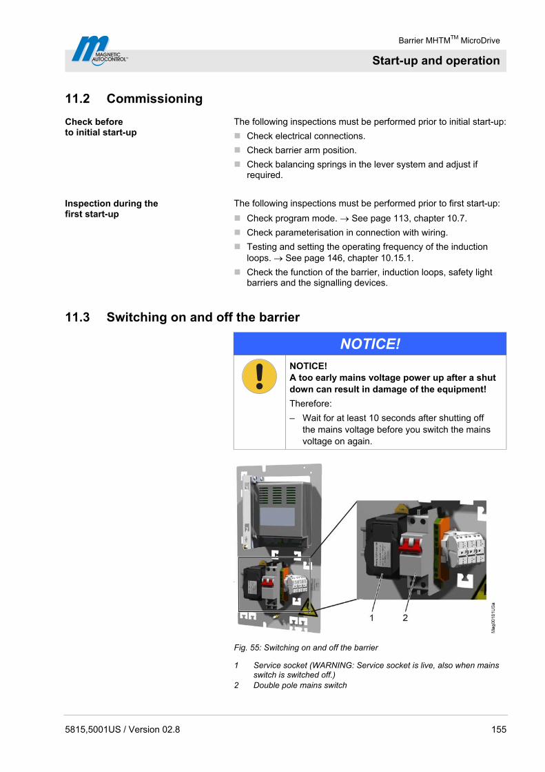
Barrier MHTMTM MicroDrive
Start-up and operation
5815,5001US / Version 02.8 155
11.2 Commissioning
Check before to initial start-up
The following inspections must be performed prior to initial start-up:
Check electrical connections.
Check barrier arm position.
Check balancing springs in the lever system and adjust if required.
Inspection during the first start-up
The following inspections must be performed prior to first start-up:
Check program mode. See page 113, chapter 10.7.
Check parameterisation in connection with wiring.
Testing and setting the operating frequency of the induction loops. See page 146, chapter 10.15.1.
Check the function of the barrier, induction loops, safety light barriers and the signalling devices.
11.3 Switching on and off the barrier
NOTICE!
NOTICE! A too early mains voltage power up after a shut down can result in damage of the equipment!
Therefore:
– Wait for at least 10 seconds after shutting off the mains voltage before you switch the mains voltage on again.
Fig. 55: Switching on and off the barrier
1 Service socket (WARNING: Service socket is live, also when mains switch is switched off.)
2 Double pole mains switch

Barrier MHTMTM MicroDrive
Start-up and operation
156 5815,5001US / Version 02.8
Switching on 1. Remove the barrier housing hood.
2. Remove the barrier housing door.
3. Switch on the barrier via the double pole mains switch.
4. Depending on the settings in the "Start-up behaviour" menu, the barrier arm slowly moves into the top end position (homing run) or stops.
5. Mount the door.
6. Attach and lock the hood.
Switching off 1. Remove the barrier housing hood.
2. Remove the barrier housing door.
3. Switch off the barrier via the double pole mains switch.
4. Depending on the settings of the lever system's balancing spring and the settings in the menu "Start-up behaviour", the barrier arm opens or closes. See page 81, chapter 8.13 and page 137, chapter 10.10.9.
5. Mount the door.
6. Attach and lock the hood.
Barrier MHTMTM MicroDrive
Start-up and operation
5815,5001US / Version 02.8 157
11.4 Putting the barrier temporarily out of operation
High wind speeds
WARNING!
WARNING! Risk of injury from barrier arm in case of high wind speeds!
The barrier arm is no longer securely locked with the mains voltage off. At high wind speeds, the barrier arm can be pressed from its end position. The moving barrier arm can severely injure a person.
Therefore:
– Keep supplying the barrier with mains voltage.
– Remove the barrier arm if necessary.
NOTICE!
NOTICE! Possible damage to the equipment by condensed water when mains voltage is switched off!
Therefore:
– Keep supplying the barrier with mains voltage.
If the barrier is put out of operation for a longer period, proceed as follows:
1. Switch off barrier. See page 155, chapter 11.3.
2. Remove the barrier arm if necessary. See page 173, chapter 14.2.
3. Protect the barrier from corrosion and contamination.
4. Switch on barrier. See page 155, chapter 11.3.
Barrier MHTMTM MicroDrive
Maintenance
158 5815,5001US / Version 02.8
12 Maintenance
12.1 Safety
See also safety notes on page 20, chapter 2.6 "Occupational safety and special dangers".
General
WARNING!
WARNING! Danger by inappropriate maintenance!
Inappropriate start-up and operation can cause severe or lethal injuries.
Therefore:
– All maintenance work must be performed by specialists or electrical specialists.
– Prior to work, ensure that there is sufficient assembly space.
– Pay attention to tidiness and cleanness at the assembly site! Loosely stacked or lying around components and tools are accident sources.
– After completion of maintenance work, ensure that all covers are correctly mounted.
– Wear protective helmet.
Personal protective equipment The following must be worn during maintenance work:
Work clothes
Protective gloves
Safety shoes
Protective helmet.
Maintenance book In barriers where personal traffic cannot be excluded, a maintenance book must be maintained.
In any other barriers, maintenance of a test book is not mandatory. However, we recommend keeping a test book in such barriers as well, to properly document all maintenance work.
Barrier MHTMTM MicroDrive
Maintenance
5815,5001US / Version 02.8 159
12.2 Cleaning
The cleaning interval essentially depends on the environmental conditions and the climate.
Aggressive cleaning aids and substances
NOTICE!
NOTICE! Unit damage possible!
Aggressive detergents and consumables may damage or destroy components, electric cables, or the coating of the barrier.
Therefore:
– Do not use cleaning agents with aggressive ingredients.
Carrying out cleaning work:
1. Switch off power supply and secure against restarting.
DANGER!
Mortal danger by electric voltage!
Keep moisture and dust away from live parts. Moisture or dust may cause a short circuit.
Never clean the barrier housing and barrier arm with vapour or pressure-jet cleaners.
2. Remove contamination from the outside of the barrier housing properly using water with washing-up liquid and a square of cloth. Do not bring control units and electrical components in contact with moisture.
3. Remove dust inside the housing with a vacuum cleaner.
4. After cleaning work, check that all previously opened covers are closed again and that all safety equipment functions correctly.

Barrier MHTMTM MicroDrive
Maintenance
160 5815,5001US / Version 02.8
12.3 Maintenance schedule
The following describes the maintenance work that is necessary for optimal, trouble-free operation. Maintenance intervals must be observed.
If increased wear of individual components or functional groups is revealed during regular inspections, the operator must reduce the required maintenance intervals on the basis of the actual signs of wear.
In case of queries regarding the maintenance work and intervals: contact the manufacturer (for service address, refer to page 2).
Interval Maintenance work To be carried out by
Visual inspection of the housing, inside and out, for damage and corrosion. Clean the housing and repair paint damage as necessary. Remove corrosion damage.
Specialist
Visual inspection of foundation anchors, U-profiles and mounting material for corrosion. Remove corrosion damage.
Specialist
Visual inspection of the barrier arm for damage and corrosion. Clean the barrier arm and repair paint damage as necessary. Remove corrosion damage.
Specialist
Visual inspection of additional parts, light barrier posts and the pendulum support for damage and corrosion. If necessary, clean additional parts, light barrier posts and pendulum support and repair paint damage. Remove corrosion damage.
Specialist
Monthly
Where they exist, inspect lenses and mirrors of the light barriers.
Specialist
Check function of the ground fault circuit interrupter (GFCI).
Electrical specialist
Check the barrier casing fastening screws for tight fit. If required, tighten the screws.
Specialist
Check the screws of the additional parts, pendulum support and light barrier post for tight fit. If required, tighten the screws.
Specialist
Every 6 months
Check the barrier arm and flange fastening screws for tight fit. If required, tighten the screws.
Specialist

Barrier MHTMTM MicroDrive
Maintenance
5815,5001US / Version 02.8 161
Interval Maintenance work To be carried out by
Check the barrier's mechanics.
Check the spring setting of the lever system.
Check barrier arm position.
Visual inspection of the induction loops and the roadway for damage.
Check the induction loops' function. See page 146.
Check the induction loops. Measure the contact resistance, insulation resistance, and inductance of the induction loops. See page 63.
Where they exist, check the function of additional safety equipment, such as light barriers.
Check the barrier's function.
Check the parameter settings. See page 106 et seq.
Check the barrier's locking in the position "Closed".
Check the advanced warning on barriers with the active function "Traffic lights lead".
Check electric cables for damages.
Check if all electrical connections are firm.
Check signs and labels for legibility.
Every 12 months
Check foundation fastening.
MHTM MicroDrive service specialist
Cleaning barrier arm. Specialist The cleaning interval depends on the environmental conditions and the climate.
Clean barrier housing from the inside. Specialist
Table 60: Maintenance schedule
Barrier MHTMTM MicroDrive
Malfunctions
162 5815,5001US / Version 02.8
13 Malfunctions
This chapter describes possible causes of malfunctions and trouble shooting tasks.
Contact your dealer in case of malfunctions that cannot be repaired by means of the following information. Procure spare parts from your dealer or directly from the manufacturer. For the address, see invoice, delivery note or the reverse of these instructions.
13.1 Safety
See also safety notes on page 20, chapter 2.6 "Occupational safety and special dangers".
General
WARNING!
WARNING! Danger of injury from inappropriate troubleshooting!
Inappropriate troubleshooting can cause severe or lethal injuries.
Therefore:
– All troubleshooting work must be performed by specialists or electronics specialists.
– Observe possible movements of the barrier arm. A defective control unit may lead to inadvertent movement of the barrier arm.
– Prior to work, ensure that there is sufficient assembly space.
– Pay attention to tidiness and cleanness at the assembly site! Loosely stacked or lying around components and tools are accident sources.
– Deactivate the barrier if any components are damaged, e.g. the barrier arm.
– After completion of troubleshooting, ensure that all covers are correctly mounted.

Barrier MHTMTM MicroDrive
Malfunctions
5815,5001US / Version 02.8 163
Danger of injury after lightning strike
WARNING!
WARNING! Danger of injury from total outage or barrier malfunction after lightning has hit the barrier!
If the barrier is struck by lightening, this may lead to total outage or malfunction of the barrier. The malfunction may cause unexpected barrier behaviour and thus lead to serious injury!
Therefore:
– If the barrier is struck by lightening, have an electrician check the barrier for damage and proper function. Repair barrier if required.
– Observe possible movements of the barrier arm. Defective control may lead to inadvertent movement of the barrier arm.
13.2 Malfunction table – barrier malfunctions
For requirements to the MHTM MicroDrive service specialist, see page 19, chapter 2.4.1.
Malfunction Possible cause Corrective action To be carried out by
No safety loop is connected to the plug-in module "Detector" and no safety light barrier to the clamps X11 and X20.
Connect either the safety loop or safety light barrier. See page 183, chapter 18.1.
Barrier out of operation. The message "Safety device missing" appears on the display.
The safety device is defective. Replace safety device.
Electrical specialist
The safety device is defective. Replace safety device. Electrical specialist
Error present. The correspond-ing error message is displayed.
Depending on error message, check components, wiring, etc.
MHTM MicroDrive service specialist
Power supply is present. Control unit display does not light up.
Control unit defective. Replace the control unit. Contact service.
MHTM MicroDrive service specialist
Loop interference due to external loop detectors or other barriers in the proximity.
Check the operating frequency of the loops and adjust if necessary
MHTM MicroDrive service specialist
Barrier does not open.
Closing signal is active. Remove closing signal Electrical specialist

Barrier MHTMTM MicroDrive
Malfunctions
164 5815,5001US / Version 02.8
Malfunction Possible cause Corrective action To be carried out by
Barrier does not open completely.
Spring tension in the balancing springs of the lever system set too weakly for the barrier arm weight.
Adjust balancing springs. See page 81, chapter 8.13.
MHTM MicroDrive service specialist
Opening signal is active for too long.
Shorten opening signal to max. 1 second.
Electrical specialist
Barrier does not close immediately after through traffic, but only after the hold-open time.
Safety loop does not respond. Check the response sensitivity of the safety loop. Adjust setting if necessary.
MHTM MicroDrive service specialist
Opening command is active. Cancel the opening command. Electrical specialist
Induction loop reports engaged, although no vehicles are present.
Check and if necessary adjust loop frequencies.
Measure loops. Insulation resistance: > 1 Mohm contact resistance: 0.8 to 2.5 ohm
Replace loop if the measured values differ from the specified values.
MHTM MicroDrive service specialist
Wire bridge between terminals X11 IN and OUT missing.
If no safety light barrier is connected, a wire bridge must be installed between the clamps X11 OUT and IN. See page 183, chapter 18.1.
MHTM MicroDrive service specialist
Barrier with Swing Away and automatic return: Wait for delay.
Operator
Barrier with Swing Away and manual return: Put barrier arm in the original position manually.
Operator
Barrier does not close.
Message "Boom contact active": At the "Boom contact" input, boom ejection was detected.
Barrier without Swing Away: Replace the barrier arm
MHTM MicroDrive service specialist
Barrier does not close. The message "Waiting for release" appears on the display.
The message appears after the voltage supply is switched on, after voltage returns and after reset.
The release signal can be given by an external closing signal or by pushing the left operating button at the control unit. See page 132, chapter 10.10.8.
Operator

Barrier MHTMTM MicroDrive
Malfunctions
5815,5001US / Version 02.8 165
Malfunction Possible cause Corrective action To be carried out by
Barrier does not close. The message "Waiting for authorization" appears on the display.
The message appears after the voltage supply is switched on, after voltage returns and after reset.
The barrier closes once a vehicle passes. See page 132, chapter 10.10.8.
Confirm message via the left button at the control device.
Operator
Spring tension in the balancing springs of the lever system set too strongly for the barrier arm weight.
Adjust balancing springs. See page 81, chapter 8.13.
MHTM MicroDrive service specialist
Barrier does not close completely.
Impact was recognized. Wait several seconds, barrier closes if no obstacle is below the barrier arm anymore.
–
Loop not connected. Connect loop
Detector mode incorrectly parameterised.
Check the parameters of the detector module and correct it if necessary. See page 145, chapter 10.15.
Loop defective. Replace loop.
Barrier does not close. The display shows:
Transfer resistance at the terminals
Cut connecting leads, strip and connect them again without end sleeves.
MHTM MicroDrive service specialist
"Safety loop" not selected for "Mode A" or "Mode B" in the menu "Detector 1 (A-B)".
Select option "Safety loop".
Cut off angle incorrectly parameterised.
Check and adjust the cut off angle.
Too low trigger sensitivity set for the loop.
Check the response sensitivity of the loop and adjust if necessary.
Inappropriate loop geometry is installed.
Install an appropriate loop geometry.
Loop interference due to external loop detectors or other barriers in the proximity.
Check the operating frequency of the loops and adjust if necessary
Safety light barrier connected incorrectly or defective.
Check safety light barrier function.
Retrofit signal light, such as red/green signal light and parameterise lead time.
MHTM MicroDrive service specialist
Barrier closes, although a vehicle is standing on the safety loop.
User misbehaviour e.g. driving into closing barrier, or following behind another vehicle.
Upgrade signs. Operator
Table 61: Malfunction table – Barrier

Barrier MHTMTM MicroDrive
Malfunctions
166 5815,5001US / Version 02.8
13.3 Warning and interference messages on the display
The control unit display indicates the corresponding warning or error message in case of an error.
Warning messages Warning messages serve as notice. The barrier continues to operate normally.
Error messages In case of error messages, the barrier is shut down. For the barrier to be started up again the error must be removed by an MHTM MicroDrive service specialist and a reset performed pursuant to chapter 13.4.
For requirements to the MHTM MicroDrive service specialist, see page 19, chapter 2.4.
13.3.1 Warning and interference messages – Logic control (Control unit)
Number Description Possible cause Corrective action
FF01 WARNING
Error barrier mechanics
The first closing motion could not be performed completely.
If required, remove obstacle below the barrier arm.
Check barrier mechanics. Check the spring setting of
the balancing springs.
FF02 WARNING
Detector monitoring signal
Communication between logic control and detector module impaired.
Perform reset. See page 170, chapter 13.4.
Check plug contacts. Clean plug contacts with
spirit. Observe ESD provisions.
Replace the control unit.
No monitoring loop is connected to the detector module and no safety light barrier to the clamps X11 and X20.
Connect either the safety loop or safety light barrier. See page 183, chapter 18.1.
Safety device defective Replace safety device.
FF03 ERROR
Monitoring device is missing
Sensitivity settings in the "Detector" menu too low. Not all vehicles are recognised.
Change sensitivity. See page 145, chapter 10.15.
FF04 ERROR
Barrier too fast Spring tension in the balancing springs of the lever system set too weakly for the barrier arm weight.
Adjust balancing springs. See page 81, chapter 8.13.
Contact service if required.
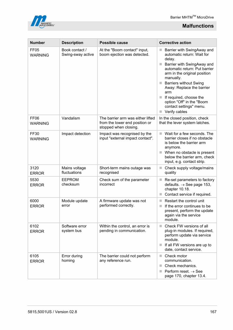
Barrier MHTMTM MicroDrive
Malfunctions
5815,5001US / Version 02.8 167
Number Description Possible cause Corrective action
FF05 WARNING
Book contact / Swing-sway active
At the "Boom contact" input, boom ejection was detected.
Barrier with SwingAway and automatic return: Wait for delay.
Barrier with SwingAway and automatic return: Put barrier arm in the original position manually.
Barriers without Swing Away: Replace the barrier arm
If required, choose the option "Off" in the "Boom contact settings" menu.
Verify cables
FF06 WARNING
Vandalism The barrier arm was either lifted from the lower end position or stopped when closing.
In the closed position, check that the lever system latches.
FF30 WARNING
Impact detection Impact was recognised by the input "external impact contact".
Wait for a few seconds. The barrier closes if no obstacle is below the barrier arm anymore.
When no obstacle is present below the barrier arm, check input, e.g. contact strip.
3120 ERROR
Mains voltage fluctuations
Short-term mains outage was recognised
Check supply voltage/mains quality
5530 ERROR
EEPROM checksum
Check sum of the parameter incorrect
Re-set parameters to factory defaults. See page 153, chapter 10.18.
Contact service if required.
6000 ERROR
Module update error
A firmware update was not performed correctly.
Restart the control unit If the error continues to be
present, perform the update again via the service module.
6102 ERROR
Software error system bus
Within the control, an error is pending in communication.
Check FW versions of all plug-in modules. If required, perform update via service module.
If all FW versions are up to date, contact service.
6105 ERROR
Error during homing
The barrier could not perform any reference run.
Check motor communication.
Check mechanics.
Perform reset. See page 170, chapter 13.4.

Barrier MHTMTM MicroDrive
Malfunctions
168 5815,5001US / Version 02.8
Number Description Possible cause Corrective action
8130 WARNING
Note monitoring Communication with a plug module was interrupted.
Check if all plugged modules are listed in the main menu.
Perform reset. See page 170, chapter 13.4.
Contact service if required.
Table 62: Warning and interference messages – logic control (control unit)
13.3.2 Warning and interference messages – Motor GW
Number Description Possible cause Corrective action
2220 WARNING
Overcurrent Overcurrent was recognised Warning may appear in connection with impact.
If no impact took place, check the cables.
Contact service if required.
3211 WARNING
Overvoltage Overvoltage was recognised Warning may appear in connection with impact.
If no impact took place, check the cables.
Contact service if required.
3221 WARNING
Undervoltage Undervoltage was recognised Warning may appear in connection with impact.
If no impact took place, check the cables.
Contact service if required.
4210 WARNING
Overtemperature A high temperature was recognised.
Check motor temperature via display. The temperature must be below 100 °C. See page 144, chapter 10.14.
Contact service if required.
4220 WARNING
Derating error Motor power intake is reduced to avoid further temperature increase.
Remove impermissible attachments
Check the spring setting of the balancing springs.
Reduce speed of the barrier arm.
Contact service if required.
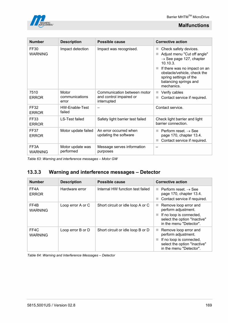
Barrier MHTMTM MicroDrive
Malfunctions
5815,5001US / Version 02.8 169
Number Description Possible cause Corrective action
FF30 WARNING
Impact detection Impact was recognised. Check safety devices. Adjust menu "Cut off angle"
See page 127, chapter 10.10.3.
If there was no impact on an obstacle/vehicle, check the spring settings of the balancing springs and mechanics.
7510 ERROR
Motor communications error
Communication between motor and control impaired or interrupted
Verify cables Contact service if required.
FF32 ERROR
HW-Enable-Test failed
– Contact service.
FF33 ERROR
LS-Test failed Safety light barrier test failed Check light barrier and light barrier connection.
FF37 ERROR
Motor update failed An error occurred when updating the software
Perform reset. See page 170, chapter 13.4.
Contact service if required.
FF3A WARNING
Motor update was performed
Message serves information purposes
–
Table 63: Warning and interference messages – Motor GW
13.3.3 Warning and interference messages – Detector
Number Description Possible cause Corrective action
FF4A ERROR
Hardware error Internal HW function test failed Perform reset. See page 170, chapter 13.4.
Contact service if required.
FF4B WARNING
Loop error A or C Short circuit or idle loop A or C Remove loop error and perform adjustment.
If no loop is connected, select the option "Inactive" in the menu "Detector".
FF4C WARNING
Loop error B or D Short circuit or idle loop B or D Remove loop error and perform adjustment.
If no loop is connected, select the option "Inactive" in the menu "Detector".
Table 64: Warning and Interference Messages – Detector

Barrier MHTMTM MicroDrive
Malfunctions
170 5815,5001US / Version 02.8
13.3.4 Warning and interference messages – All modules
Number Description Possible cause Corrective action
6010 WARNING
Watchdog reset SW error Contact service if required.
8110 WARNING
Bus fault Warning Contact service if required.
8120 WARNING
Bus HW fault Warning Check DIP switch next to service interface (position ON)
Remove devices at service interface if required.
Table 65: Warning and interference messages – All modules
13.4 Reset the barrier
Control unit reset is performed as follows:
Switch of power supply and switch it on again after 10 seconds.
or
Press the two middle control buttons on the display for 5 seconds. See page 107, Fig. 46.
NOTICE!
NOTICE! Damage to the unit by too-short switching intervals of the mains voltage!
Therefore:
– To avoid damage to the equipment the power must remain shut off for at least 10 seconds.

Barrier MHTMTM MicroDrive
Malfunctions
5815,5001US / Version 02.8 171
13.5 Closing or opening the barrier arm in case of power failure
In case of power failure, the barrier arm may be in the lower or upper dead point. I.e. the barrier arm can no longer be easily moved manually. In this case, proceed as follows:
1. Remove the barrier housing hood.
2. Remove the barrier housing door.
3. Press a tool straight into the lower tool bore. The lever arm is pressed from the dead point
Upper tool bore for opening the barrier.
Lower tool bore for closing the barrier.
4. Mount the door if applicable.
5. Attach and lock the hood if applicable.
Ma
g0
02
09
1
2
Fig. 56: Top and bottom tool bore
1 Upper tool bore for opening the barrier. 2 Lower tool bore for closing the barrier.
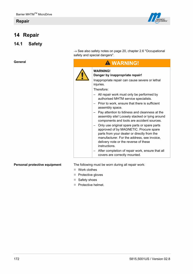
Barrier MHTMTM MicroDrive
Repair
172 5815,5001US / Version 02.8
14 Repair
14.1 Safety
See also safety notes on page 20, chapter 2.6 "Occupational safety and special dangers".
General
WARNING!
WARNING! Danger by inappropriate repair!
Inappropriate repair can cause severe or lethal injuries.
Therefore:
– All repair work must only be performed by authorised MHTM service specialists.
– Prior to work, ensure that there is sufficient assembly space.
– Pay attention to tidiness and cleanness at the assembly site! Loosely stacked or lying around components and tools are accident sources.
– Only use original spare parts or spare parts approved of by MAGNETIC. Procure spare parts from your dealer or directly from the manufacturer. For the address, see invoice, delivery note or the reverse of these instructions.
– After completion of repair work, ensure that all covers are correctly mounted.
Personal protective equipment The following must be worn during all repair work:
Work clothes
Protective gloves
Safety shoes
Protective helmet.

Barrier MHTMTM MicroDrive
Repair
5815,5001US / Version 02.8 173
14.2 Spare parts
WARNING!
WARNING! Risk of injury by incorrect spare parts!
Incorrect or defective spare parts can result in damage, malfunctions or total failure and also impair safety.
Therefore:
– Use only the manufacturer's original spare parts.
Procure spare parts from your dealer or directly from the manufacturer. For the address, see invoice, delivery note or the reverse of these instructions.
Spare part lists can be obtained on request.
14.3 Replacing the barrier arm
Danger of injury
CAUTION!
CAUTION! Danger of injury!
There is a danger of injury when mounting the barrier arm.
Therefore:
– Barrier arms as of a length of 14.8 ft (4.5 m) must be installed by two persons. We recommend also installing shorter barrier arms with two persons.
14.3.1 Barrier arm type "VarioBoom" and "MicroBoom"
Do not grease
NOTICE!
NOTICE! Improper lubrication of components, in particular the counter bearing or flange shaft, may lead to damage of the equipment!
Therefore:
– Do not grease the counter bearing and flange shaft.

Barrier MHTMTM MicroDrive
Repair
174 5815,5001US / Version 02.8
1. Secure barrier danger area e.g. with barrier tape.
2. Remove the barrier housing hood.
3. Remove the barrier housing door.
WARNING!
Danger of crushing between barrier arm and barrier housing!
4. Switch off power supply. Ensure that the system is powered down. Secure against reactivation.
5. The barrier must be open. Open barrier arm manually if required.
6. Disassemble flange from the flange shaft together with the barrier arm. For this, loosen the 4 hexagon socket screws 10 AF at the flange.
7. Remove the flange with the barrier arm.
Ma
g0
01
75
Fig. 57: Disassemble flange with barrier arm
8. Remove flange from the barrier arm. For this, loosen the 4 hexagon socket screws 5 AF at the barrier arm. Use slot nuts for the new barrier arm.
Ma
g0
01
76
Fig. 58: Disassemble flange
9. Replacing the barrier arm.

Barrier MHTMTM MicroDrive
Repair
5815,5001US / Version 02.8 175
10. Remove end cap from the barrier arm.
Mag00170
Fig. 59: Disassemble end cap
11. Slide a slot nut into the groove at the underside of the barrier arm. Place a slot nut on the upper side of the barrier arm.
Ma
g0
01
71
Fig. 60: Assemble slot nuts
12. Attach the flange with the 4 hexagon socket screw and the two slot nuts to the barrier arm. The shorter protrusion of the flange must point towards the barrier arm end. Tighten screws twice in sequence to ensure that all screws are tightened correctly.
Use a torque wrench with hexagon socket: 5 AF
Tightening torque: 11.801 lbf ft (16 Nm)
Ma
g0
01
73
Fig. 61: Assembling flange
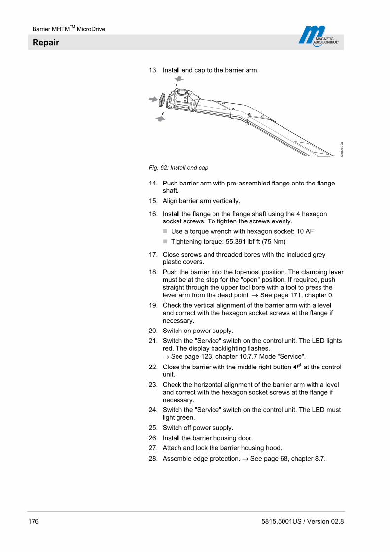
Barrier MHTMTM MicroDrive
Repair
176 5815,5001US / Version 02.8
13. Install end cap to the barrier arm.
Mag00172a
Fig. 62: Install end cap
14. Push barrier arm with pre-assembled flange onto the flange shaft.
15. Align barrier arm vertically.
16. Install the flange on the flange shaft using the 4 hexagon socket screws. To tighten the screws evenly.
Use a torque wrench with hexagon socket: 10 AF
Tightening torque: 55.391 lbf ft (75 Nm)
17. Close screws and threaded bores with the included grey plastic covers.
18. Push the barrier into the top-most position. The clamping lever must be at the stop for the "open" position. If required, push straight through the upper tool bore with a tool to press the lever arm from the dead point. See page 171, chapter 0.
19. Check the vertical alignment of the barrier arm with a level and correct with the hexagon socket screws at the flange if necessary.
20. Switch on power supply.
21. Switch the "Service" switch on the control unit. The LED lights red. The display backlighting flashes. See page 123, chapter 10.7.7 Mode "Service".
22. Close the barrier with the middle right button at the control unit.
23. Check the horizontal alignment of the barrier arm with a level and correct with the hexagon socket screws at the flange if necessary.
24. Switch the "Service" switch on the control unit. The LED must light green.
25. Switch off power supply.
26. Install the barrier housing door.
27. Attach and lock the barrier housing hood.
28. Assemble edge protection. See page 68, chapter 8.7.
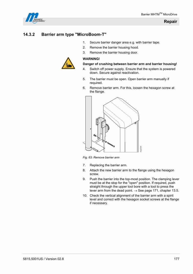
Barrier MHTMTM MicroDrive
Repair
5815,5001US / Version 02.8 177
14.3.2 Barrier arm type "MicroBoom-T"
1. Secure barrier danger area e.g. with barrier tape.
2. Remove the barrier housing hood.
3. Remove the barrier housing door.
WARNING!
Danger of crushing between barrier arm and barrier housing!
4. Switch off power supply. Ensure that the system is powered down. Secure against reactivation.
5. The barrier must be open. Open barrier arm manually if required.
6. Remove barrier arm. For this, loosen the hexagon screw at the flange.
Mag00266
Fig. 63: Remove barrier arm
7. Replacing the barrier arm.
8. Attach the new barrier arm to the flange using the hexagon screw.
9. Push the barrier into the top-most position. The clamping lever must be at the stop for the "open" position. If required, push straight through the upper tool bore with a tool to press the lever arm from the dead point. See page 171, chapter 13.5.
10. Check the vertical alignment of the barrier arm with a spirit level and correct with the hexagon socket screws at the flange if necessary.
Barrier MHTMTM MicroDrive
Decommissioning, disassembly and disposal
178 5815,5001US / Version 02.8
11. Switch on power supply.
12. Switch the "Service" switch on the control unit. The LED lights red. The display backlighting flashes. See page 123, chapter 10.7.7 Mode "Service".
13. Close the barrier with the middle right button at the control unit.
14. Check the horizontal alignment of the barrier arm with a level and correct with the hexagon socket screws at the flange if necessary.
15. Switch the "Service" switch on the control unit. The LED must light green.
16. Switch off power supply.
17. Install the barrier housing door.
18. Attach and lock the barrier housing hood.
15 Decommissioning, disassembly and disposal
A barrier that is no longer usable should not be recycled as a complete unit, but disassembled into individual components and recycled according to material types. Non-recyclable materials have to be disposed of in an environmental-friendly manner.
Decommissioning, disassembly and disposal of the barrier may only be carried out by specialised staff.
Disassemble the barrier in reverse order from assembly.
The barrier has to be disposed of in accordance with the respective country-specific regulations.
NOTE!
For expert information regarding disposal of electric equipment contact MAGNETIC or competent electricians.

Door, Drapery, Gate, Louver and Window Operators and Systems Certified for Canada
For commercial and Industrial use, Gate operators, Models LS130-01, -10, -11, -41, MIB20, MIB30, MIB35, MIB40, MSE3, MSV3, MSV4, MSV5,
followed by X-YYY, where "X" is R or L and "YYY" is any number 000 thru 999, MTS-8.
Models MBE30, MBE35, MBE50, followed by X-Cyyy, where "X" is R or L and yyy is 000 thru 999.
Vehicular barrier gate operators, Series ACCESS, ACCESS PRO and ACCESS SEL, may be followed by L or H, followed by L or R, followed by C,
followed by three digits, may be followed by one or two digits.
Vehicular barrier gate operators, Series PARKING, PARKING PRO and PARKING SEL, may be followed by H, followed by L or R, followed by C,
followed by three digits, may be followed by one or two digits.
Vehicular barrier gate operators, Series TOLL and TOLL PRO, followed by L or R, followed by C, followed by three digits, may be followed by
one or two digits.
Copyright © 2011 Underwriters Laboratories Inc.®
The appearance of a company's name or product in this database does not in itself assure that products so identified have been manufactured
under UL's Follow-Up Service. Only those products bearing the UL Mark should be considered to be Listed and covered under UL's Follow-Up
Service. Always look for the Mark on the product.
UL permits the reproduction of the material contained in the Online Certification Directory subject to the following conditions: 1. The Guide
Information, Designs and/or Listings (files) must be presented in their entirety and in a non-misleading manner, without any manipulation of the
data (or drawings). 2. The statement "Reprinted from the Online Certifications Directory with permission from Underwriters Laboratories Inc." must
appear adjacent to the extracted material. In addition, the reprinted material must include a copyright notice in the following format: "Copyright ©
2011 Underwriters Laboratories Inc.®"
FDDR7.E136510
Door, Drapery, Gate, Louver and Window Operators and Systems Certified for
Canada Page Bottom
See General Information for Door, Drapery, Gate, Louver and Window Operators and Systems Certified for Canada
MAGNETIC AUTOCONTROL GMBH E136510
GRIENMATT 20
79650 SCHOPFHEIM, GERMANY
Last Updated on 2011-06-14
Questions? Print this page Notice of Disclaimer Page Top

Barrier MHTMTM MicroDrive
180 5815,5001US / Version 02.8


Barrier MHTMTM MicroDrive
182 5815,5001US / Version 02.8

Barrier MHTMTM MicroDrive
Appendix
5815,5001US / Version 02.8 183
18 Appendix
18.1 Wiring diagrams
Following wiring diagrams apply to standard barriers. Observe the customer specific wire diagrams for customer specific barriers if applicable.

Barrier MHTMTM MicroDrive
Appendix
184 5815,5001US / Version 02.8
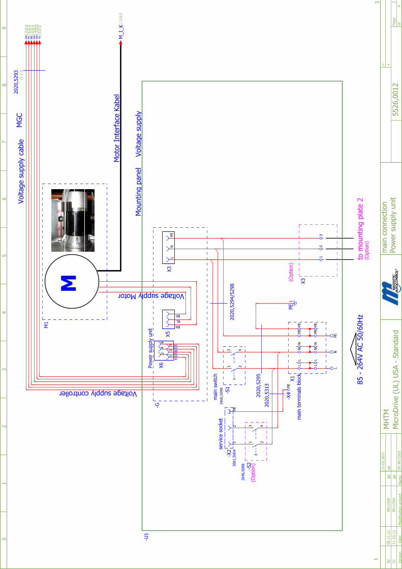
Page
of
MicroDrive (UL) USA - Standard
5526,0012
MHTM
00 5K11502
+
4
2
=
12
34
56
78
9
3
main connection
Power supply unit
0
1
01 11.10.11 5K11554 gp
02 08.11.11 5K11560 gp
11.02.2011
gp
Date
Name
Modification project
Version
85 - 264V AC 50/60Hz
M
BN
BL
BK
YEWHGRBNGNGN
Mounting panel
Voltage supply Motor
Voltage supply controller
Motor Interface Kabel
Voltage supply
main switch
service socket main term
inals block
Power supply unit
MGC
Voltage supply cable
1 2
3 4
-S1
3460,5098
(Option)
to mounting plate 2
(Option)
1 2
3 4
-S2
3046,5098
(Option)
LL
NN
PE
PE
X1
LL
NN
PE
PE
1PE
12
PE
-X2
3061,5004
LN
PE
LN
PE
13
5
24
6
-G
-U1
/3.1:2
2020,5293
X6
X5
X3
12
3
X3
M1
2020,5294/5298
2020,5313
2020,5295
-X4
PE
PK/3.0:2
GR/3.0:2
YE/3.0:2
GN/3.0:2
BR/3.0:2
WH/3.0:2
M_I_K/3.0:2


Page
of
MicroDrive (UL) USA - Standard
5526,0012
MHTM
00 5K11502
+
4
3
=
12
34
56
78
9
4
barrier controller MGC
input/output
0
2
01 11.10.11 5K11554 gp
02 08.11.11 5K11560 gp
11.02.2011
gp
Date
Name
Modification project
Version
GNPK
WH
BRGR
YE
R
E
R
E
Voltage supply cable
Bat
F
Relay 1
Relay 3
Relay 4
Relay 5
Relay 6
Relay 2
barrier controller
Inputs
24V DC
Transistor
Relay Outputs
signal light
safety light barrier
boom contact
if no safety light barrier
is connected, place
jumper
MGC
MGC
inductive loop detector
Module
Outputs
motor Interface cable
AB
BA
loops
A1
A2
B1
B2
X12
X9
boom locking
pulse after passage
A
signal lightB
(Option)
open low priority
external Opening loop Exit
close
openwith vend count
open high priority
close
open low priority
closed
Common Relais 1 - 3
loop active A
Common Relais 4 - 6
error
open
C signal light
loop active B
0V_1
A1
A2
A1
Loop
DO5
EN
P
0V
OUT
0V
IN
0V
/2.8:2
2020,5293
B1B2
X10
0V_2
0V_3
24V_1
24V_2
24V_3
IN1
IN2
IN3
IN4
IN5
IN6
IN7
IN8
COM
DO1
0V_1
DO2
0V_2
0V_3
0V_4
DO3
DO4
NO1
NO2
NO3
COM1-3
NO4
NC4
NO5
NC5
NO6
NC6
COM4-6
-X1
-X2
-X20
-X11
-X4
-X3
BL
BK
BN
-B1
+-
P_1/4.0:2
OUT/4.0:2
0V_1/4.0:2
IN/4.0:2
0V_2/4.0:2
P_2/4.0:2
GN
/2.9:2
PK
/2.9:2
BR
/2.9:2
GR
/2.9:2
WH
/2.9:2
YE
/2.9:2 M
_I_K
/2.9:2


Page
of
MicroDrive (UL) USA - Standard
5526,0012
MHTM
00 5K11502
+
4
4
=
12
34
56
78
9
safety-light barriers Option
0
3
01 11.10.11 5K11554 gp
02 08.11.11 5K11560 gp
11.02.2011
gp
Date
Name
Modification project
Version
BN
BL
WH(n.c.)
BK
BK
n.c.
BL
BN
Transm
itter
A2
3279,5028
24V
N.C.
N.C.
T
Receiver
A3
3279,5029 24V
Q 0V
Q
P_1
/3.9:2
P_2
/3.9:2
OUT
/3.9:2
0V_1
/3.9:2
0V_2
/3.9:2
IN/
3.9:2

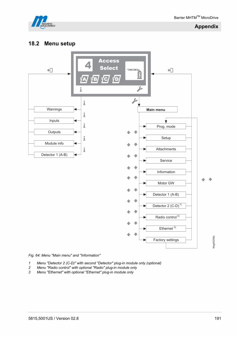
Barrier MHTMTM MicroDrive
Appendix
5815,5001US / Version 02.8 191
18.2 Menu setup
Ma
g0
02
56
a
A B DC
Access
Select4
1)
Service
Information
Motor GW
Detector 1 (A-B)
Radio control
Main menu
Prog. mode
Setup
Attachments
Ethernet
Factory settings
Detector 2 (C-D)
2)
3)
Warnings
Inputs
Detector 1 (A-B)
Outputs
Module info
Fig. 64: Menu "Main menu" and "Information"
1 Menu "Detector 2 (C-D)" with second "Detector" plug-in module only (optional) 2 Menu "Radio control" with optional "Radio" plug-in module only 3 Menu "Ethernet" with optional "Ethernet" plug-in module only
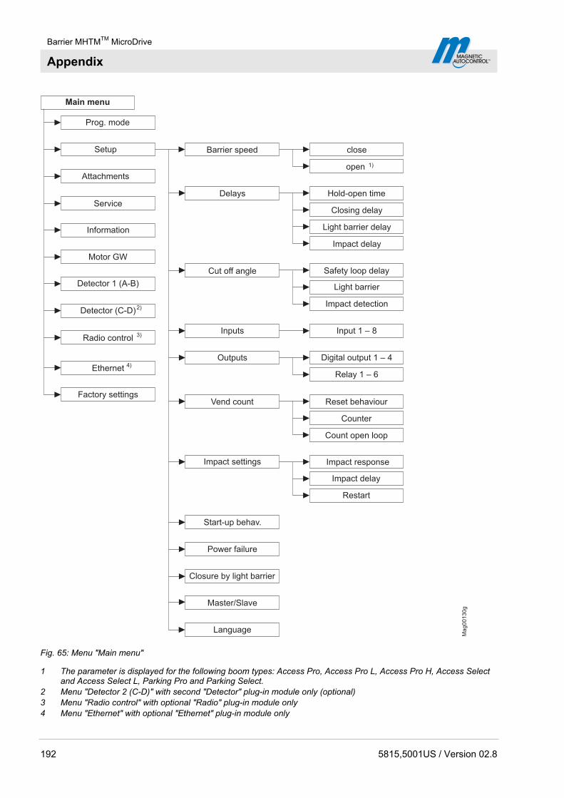
Barrier MHTMTM MicroDrive
Appendix
192 5815,5001US / Version 02.8
Mag00130g
Master/Slave
2)
Service
Information
Motor GW
Detector 1 (A-B)
Detector (C-D)
Cut off angle
Inputs
Outputs
Vend count
Impact settings
Main menu
Prog. mode
Attachments
Barrier speed
Delays
open
close
Hold-open time
Closing delay
Light barrier delay
Impact delay
Safety loop delay
Light barrier
Impact detection
Input 1 – 8
Digital output 1 – 4
Relay 1 – 6
Impact response
Impact delay
Restart
Setup
Reset behaviour
Counter
Start-up behav.
Factory settings
Language
Power failure
Closure by light barrier
3)Radio control
4)Ethernet
1)
Count open loop
Fig. 65: Menu "Main menu"
1 The parameter is displayed for the following boom types: Access Pro, Access Pro L, Access Pro H, Access Select and Access Select L, Parking Pro and Parking Select.
2 Menu "Detector 2 (C-D)" with second "Detector" plug-in module only (optional) 3 Menu "Radio control" with optional "Radio" plug-in module only 4 Menu "Ethernet" with optional "Ethernet" plug-in module only
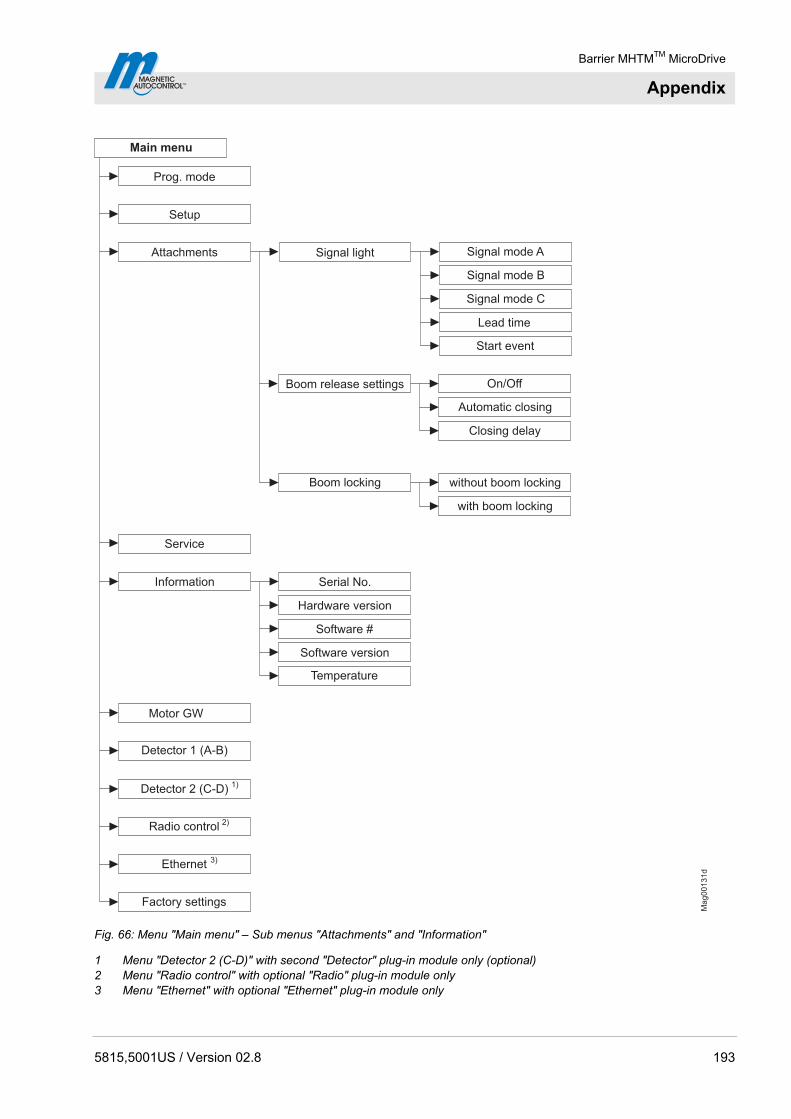
Barrier MHTMTM MicroDrive
Appendix
5815,5001US / Version 02.8 193
Mag00131d
2)
Software #
Service
Information
Motor GW
Detector 1 (A-B)
Factory settings
Prog. mode
Setup
Temperature
Hardware version
Software version
Serial No.
Signal light Signal mode A
Signal mode B
Lead time
Start event
Boom release settings On/Off
Automatic closing
Closing delay
Attachments
Signal mode C
Boom locking without boom locking
Main menu
Radio control
with boom locking
Detector 2 (C-D)
Ethernet 3)
1)
Fig. 66: Menu "Main menu" – Sub menus "Attachments" and "Information"
1 Menu "Detector 2 (C-D)" with second "Detector" plug-in module only (optional) 2 Menu "Radio control" with optional "Radio" plug-in module only 3 Menu "Ethernet" with optional "Ethernet" plug-in module only

Barrier MHTMTM MicroDrive
Appendix
194 5815,5001US / Version 02.8
Ma
g0
02
11
c
2)Radio control
Delete remote control
Teach in remote control
Information
Number of transmitter
Freq. A
Freq. B
Freq. shift
Ref. A
Ref. B
Sensitivity B
Frequency settings
Information
Service
Information
Motor GW
Detector 1 (A-B)
Factory settings
Recalibration
Mode A
Mode B
Sensitivity A
Channel A
Channel B
Prog. mode
Setup
Attachments
Main menu
Ethernet
1)
3)
Detector 2 (C-D)
Software #
SW Version
Motor temperature
Motor-SW
Fig. 67: Menu "Main menu" – Sub menus "Motor GW", "Detector 1 (A–B)" and " Radio control"
1 Menu "Detector 2 (C-D)" with second "Detector" plug-in module only (optional) 2 Menu "Radio control" with optional "Radio" plug-in module only 3 Menu "Ethernet" with optional "Ethernet" plug-in module only
Barrier MHTMTM MicroDrive
Index
5815,5001US / Version 02.8 195
Index
A
Assemble housing ..............................................66 Assembly
Housing...........................................................66 Safety light barrier...........................................69
Assembly and installation Required steps................................................55
Assembly site .....................................................57 Light barrier posts ...........................................59
B
Balancing springs ...............................................82 Check..............................................................81 Setting.............................................................81
Barrier arm..............................................43, 44, 45 Barrier housing .......................................43, 44, 45 Bistable.............................................................116
C
Change value ...................................................107 Changes .............................................................18 Check
Assembly ........................................................87 Before to initial start-up.................................155 Electrical connection .....................................105 Installation.......................................................87
Check assembly .................................................87 Check installation ...............................................87 Cleaning............................................................159 Commissioning .................................................155 Connecting mains supply ...................................91 Control buttons
Function ........................................................108 Control elements ..............................................106 Control unit
Displays ........................................................107 Technical data.................................................41
Control unit control elements............................106 Copyright ............................................................13 Customer service................................................14
D
Danger area........................................................28 Deadman ..........................................................115 Decommissioning .............................................178
Temporarily ...................................................157 Design.................................................................43 Digital inputs .......................................................98 Digital outputs...................................................101 Dimensions
Access.............................................................31 Access Pro H ..................................................34 Parking ............................................................37 Toll...................................................................39
Disassembly .....................................................178 Display
Symbols ........................................................108 Disposal ............................................................178
E
Electrical connection...........................................88 Electrical specialists............................................19 Empty conduit
Light barrier ...............................................59, 60 Empty conduits .............................................57, 58 Environmental protection....................................15
F
Foundation................................. 43, 44, 45, 57, 58 Light barrier post .............................................60 Light barrier posts ...........................................59
Foundation plan ............................................58, 60 Function ..............................................................46
G
General ...............................................................11 Grant of equipment authorization .....................181
H
Hazard Notes......................................................21
I
Identification........................................................29 Induction loops....................................... 61, 64, 65 Inspection
During the first start-up..................................155 Instructed People................................................19 Intended use .......................................................16
L
Limitation of liability.............................................13 Loop detector plug-in module
Technical data.................................................42 Lorry loops ..........................................................51 Lorry/passenger car loops ..................................52
M
Maintained contact............................................114 Maintenance .....................................................158 Maintenance schedule......................................160 Malfunction Table .............................................163 Malfunctions......................................................162

Barrier MHTMTM MicroDrive
Index
196 5815,5001US / Version 02.8
Master .............................................................. 138 MHTMTM MicroDrive service expert ................... 19 Modifications ...................................................... 18 Mounting material
Requirements........................................... 66, 68
O
Occupational safety ..................................... 20, 21 Open/Closed button......................................... 117 Operating Instructions........................................ 11 Operating Personnel
Requirements................................................. 19 Operational view .............................................. 107 Output relay ..................................................... 101
P
Parallel operation............................................. 138 Parameterising
Options ......................................................... 111 Values .......................................................... 112
Passenger car loops .................................... 50, 51 Pendulum support........................................ 43, 44 Personal protective equipment .......................... 20 Pictogram explanation ....................................... 12 Program mode
Deadman...................................................... 115 Maintained contact ....................................... 114 Pulse control................................................. 116 Two-Pulse control ........................................ 117
Pulse control .................................................... 116
R
Radio plug-in module Technical data................................................ 42
Reinforcement.............................................. 57, 58 Reset barrier .................................................... 170
S
Safety................................................................. 16 Commissioning............................................. 154 Electrical connection ...................................... 88 Maintenance................................................. 158 Malfunctions ................................................. 162 Operation...................................................... 154 Repair........................................................... 172
Transport ........................................................ 47 Safety devices
Plausibility check ............................................ 95 Safety Instructions ............................................... 3 Safety light barrier.............................................. 69 Scope of delivery ............................................... 14 Select program mode....................................... 113 Service switch .................................................. 123 Setup
Program mode.............................................. 113 Slave ................................................................ 138 Spare parts....................................................... 173 Specialised Staff ................................................ 19 Specialists
Requirements ................................................. 19 Storage............................................................... 49 Switching off..................................................... 156 Switching on..................................................... 156 Symbols
Control button functions ............................... 108 Current program mode ................................. 110 Current state of the barrier ........................... 109 Current state of the induction loops ............. 110 Further .......................................................... 110
T
Technical data.................................................... 31 Transport............................................................ 49 Transport inspection .......................................... 48 Two-Pulse control ............................................ 117 Type code .......................................................... 30 Type plate .......................................................... 29
U
UL-Declaration ................................................... 14 Unpacking .......................................................... 66
V
VarioBoom ......................................................... 43
W
Warning notes .................................................... 12 Warning signs .................................................... 87 Warranty............................................................. 14

Barrier MHTMTM MicroDrive
5815,5001US / Version 02.8 197

F05475758
MAGNETIC Automation Corporation 3160 Murrell Road Rockledge, Florida, 32955 USA Tel.: +1 321 635 8585 Fax.: +1 321 635 9449 E-Mail: [email protected] Internet: www.ac-magnetic.com
Address sales partner: