barc rt level ii.pdf
TRANSCRIPT

7/22/2019 BARC RT LEVEL II.PDF
http://slidepdf.com/reader/full/barc-rt-level-iipdf 1/160
, eM 1wFAMx r' .:M.;.wahn qcnov.. I/11111'fRCU''f,/lips man cfl/ ' nrc f .r,.r, r cavry , v; ICJd+llrt• r/i s,.' h L ' ^ 1 ^ ^ !1G. i^7rt^ ',
r /.•:r nn,y!nfllfi• 1rttf..:x:L:;
TRAINING COURSE ON
MUSTRIAL RADIOGRAPHY TESTING
AND SAFETY - (RT-1)
(VOLUME - 1)
N u i - K A-rJ^oG^RA F^
Compilcd by
GURSI-TAR AN SINGH
Isotope Division, BAR C
AND
M.J. SUBRAMANYA
Radiological Physics and Advisory Division, BARC
RADIOLOGICAL PHYSICS AND ADVISORY DIVISION
BHABHA A'T'OMIC RESEARCH CENTRE
NIUMBAI 400 085
1997
AFiu LRQr1t^i S^ ^(n

7/22/2019 BARC RT LEVEL II.PDF
http://slidepdf.com/reader/full/barc-rt-level-iipdf 2/160
= n e +

7/22/2019 BARC RT LEVEL II.PDF
http://slidepdf.com/reader/full/barc-rt-level-iipdf 3/160
CONTENTS
1. A. Non-Destructive Testing Methods
B. Properties of Materials
C. Defects in Materials
D. Material Defects and Failures in Service
2. A. X-ray Technology
B. Radiation Sources
C. Gamma Radiography Equipment
3. A. Photographic and Non-Photographic Recording
B. Lead and Fluorescent Screens
4. A. Work Parameters and Conditions-
B. Evaluation of Radiographic Quality
5. Defectolo gy
6. Selection of Radiography Techniques
7. Radiographic Standards and Selection of Test . Methods
8. Advances in Radiography

7/22/2019 BARC RT LEVEL II.PDF
http://slidepdf.com/reader/full/barc-rt-level-iipdf 4/160

7/22/2019 BARC RT LEVEL II.PDF
http://slidepdf.com/reader/full/barc-rt-level-iipdf 5/160
•CJ?. ,wJl ... w®. ,,ryuur'ai MRiGw
rtNwMw,. . I111hC
rl"two . iy(W
.h.•i. i.nvrlw 1 frwfAL" L O +"1 .J /tw f.... -i' :... t, ,,.: .,, ee_
1A NON-DESTRUCTIVE TESTING METHODS
1: INTRODUCTION0
'Non-destructive testing (NDT)' is testing materials withourdestroying them . The materials.
after inspection do not change in their size, shape , physical or chemical properties.
Mhere are six major NDT methods viz., visual and optical aids; die rah testing, ul asonic
testing, eddy cuirent testing, magnetic particle testing and dye penetrant testing. q h se are
regularly used by industry. IEach of these methods, has its own flaw detection capability and therefore no method can
replace other methods. These methods are discussed in brief.
2: TYPES OF NDT METHODS
Commonly employed NDT methods can be broadly divided. into two groups
i) Methods for detection ')f internal defects
ii) Methods for inspection of surface/sub-surface defects
3: METHODS FOR INTERNAL FLAWS
'3.1 : Radiographic Method
Basic principle of radiographic testing is shown in figure 1.1. The radiation transmitted
.through a material, is recorded on an X-ray film. In this method, different types of radiations
and films are u,ed, depending upon the type of information required.
ZObect
Defect
Distribution of
E- transmitted intensity
through the object
F i g : 1 . 1 : P r i n c i p l e o f R a d i o g r a p h y T e s t i n g .
1.1

7/22/2019 BARC RT LEVEL II.PDF
http://slidepdf.com/reader/full/barc-rt-level-iipdf 6/160
3.1.1: X and G a m m a Radiography
of blackening) variation depending on the internal structure of the object.
assemblies . The image of a material produced on an X-ray film shows optical density (degree
Radiography testing is most widely used in industry for inspection of welds, castings and
Industrial X-ray machines " " in the range of 50-400 kV are used for inspection of meta)
thicknesses ul;-to 7.5 cm steel equivalents. Betatrons and linear accelerators upto 30 MeV are_
combined together can cover inspection range of 10-200 mm of steel equivalents.
Artifi4ially producedoduced' radioisotopes. emitting gamma radiations., such as iridium-192 and
cobalt 60 have many advantages over X-ray machines. Equipment used for gamma
radiography is compact, rugged and ideal for field work. Iridium-192 and cobalt-60 sources
used is r highr T thicknesses..
3.2 : Ultrasonic Method
Ultrasound waves are generated by piezo electric ransducers which convert electrical energy
to mechanical vibrations and vic-versa . These waves are made ' to fall on the material to betested . As the wave travels through the material, it may get reflected , refracted , scattered ortransmitted depending upon the structure of the material.
Longitudinal
waves
7/77 /
x x
!
a. Pulsecho Method b. Transmssion Mediod
Fig. 1.2 : Ultrasonic Methods
Most commonly used frequency range for industrial inspec rion is 0 .5 - 25 mega llerrz. Three
important methods of ultrasonic testing are pulse-echo , transmission aid resonance techniques.
3.2.1 : Pulse-Echo Method
In this method, evenly timed pulse waves are transmitted into the material to be tested. Inahomogeneous material, the wave travels through the material and gets reflected from the back
swfaee. in case of a aefect, the original pulse reflects back from-the. defect loce.tion and
returns to the transducer before the return of hack surface echo pulse as shown in figure I.2a"
A single transducer canOerve both as.transrnirter and receiver.
1.2

7/22/2019 BARC RT LEVEL II.PDF
http://slidepdf.com/reader/full/barc-rt-level-iipdf 7/160
->.. MT,w..I.......r!N14 I. IIWWN.. 1•lwta w.uylclll(WJd.
It
l
3.2.2 :.Transmission Method
^ Ill III' hcm'1 gthedtywd i c,.ue/.uJw•.,1•,n+^r/avrY ' l/iar^»•^•^•av,t !t flu'fridtL• IWIIr#t1.e f, •u(1... t ,.... 1.._I .,
In this method, two separate transducers are used on.either.side of the material, one as
transmitter and the other as receiver (Fig. 1.20) Variation in intensity across the-transmitted
beam indicates the soundness of the material. Attenuation of the sound beam is indicative of
coarse grain structure of the material. When the wave length is comparable to the grain size
of the medium, scattering process predominates.. Transmission method is less sensitive.
3.2,3: Resonance Method
This method is mainly useful for measurement of thickness of plates -r sheets and also in caseof bonded materials . In this method, ultrasonic wave of continuously varying frequency is fedinto the material .. The frequency is varied till a standing wave is set up within the material,
causing it to resonate at the fundamental frequency or multiples of it at a greateramplitude asshown in figure 1.3. The resonance is sensed by an instrument. Change in resonant frequency
is an indication of discontinuity.
Fig. L3 : Principle of Resonance method.
4: METHODS FOR SURFACE/SUB-SURFACE INSPECTIONS
4.1.: Visual aid Dye . Penetrant Testing Methods
Examination of cracks and other irregularities on the surface under visible light is the cheapest,
. - simplest and qu ckest NDT method. However, all . defects cannot be seen , byvnaiddd eyes.Therefore, techr.iques to increase the contrast of the discontinuity to make it visible , are used.Coloured and fluorescent dyes are made to seep into the surface cracks to provide contrast
against the background.
?.3

7/22/2019 BARC RT LEVEL II.PDF
http://slidepdf.com/reader/full/barc-rt-level-iipdf 8/160
4.2 : Rayleigh Wave Testing
Rayleigh waves are ultrasonic shear waves propa ated ne har t e surface of a material . Waves'f frequencies in the rangeof 1-10 MHz are used for detection of surface cracks and other
defects. The technique is used, where access is limit d .
4.3 : Magnetic Particle Testing
This,method is applicable onl y to materials which can be rnagnetisec '_ The object ismagnetised by applying high alternate or direct currents (A.C or D.C) and flow of magnetic'powders is observed either in dry or wet process . Surface discontinuity, such as grinding"racks , forging laps and seams, etc. can be easily detected . In some cases , sub-surfacedefects about one centimeter deep, can also be revealed.
COIL
Fig. 1.4 : Principle of Eddy Current Testing
4.4 : Eddy Current Testing
The method employs alternating currents i{ the range (50-5000 kHz),.and is useful for detection
of surface and near surface defects in electrically conducting materials. When a coilcarrying
alternating current is placed in the proximity of metal specimen, as shown in'figure 1.4eddy
currents are induced on the surface layer. Strength of these eddy currents depends on z la; n:^number of surface variables.
1.4 L ' o a U rv u A .h l
yam- { y ry y
c V4 v7.ECiK^'^^,, I^^..Zi'MrJ^ GaMSr_
4'

7/22/2019 BARC RT LEVEL II.PDF
http://slidepdf.com/reader/full/barc-rt-level-iipdf 9/160
. C
(
(
wsyy,^7tnttk'a rXilie^-,rw«. ^ t ra,..W . r uw
, ,Depth. of inspection depends upon type-of material and frequency of the alternating current and itis 'about • 140 mm:
5 LEAKTESTING
Leak testing ,method is used-to check fabricat ed components and systems , ifor nuclear reactors,pressure-vessels, electronic valves ,. vacuum equipment , gas containers, etc . ; A leak is passage of
:,a gas frpm one side of the w all of the container to t he other side, un er pressure or concentrati ondifference . It is*m easured as cc/sec.
Depending upon the range of leak , detection capability , a number ofl test - methods are available.Some examples are; pressure*drop /rise, ultrasonic leak detectors, bubble tests and ammonia
sensitised paper, with detection capabilities upto 10-4 cc/sec. Halogen diode sniffer, Helium
mass spectrometer and Argon mass spectrometer have detection sensitivities in the range
10-' 10.11 cc/sec.
. ar•_.. :•_. _ «. i. .
ffisagz

7/22/2019 BARC RT LEVEL II.PDF
http://slidepdf.com/reader/full/barc-rt-level-iipdf 10/160
1B• PROPERTIES OF MATERIA,LS
X NTRODUCTION
Selection of a material for a given job depends upon its physical and iMost structural mat mech i 'nr calls properties.alare subject to external forces, an
which generate internal metressesThe reaction of the part to these str
Hence esses can be critical to its continued fun t onin ^, it is important for the NDT personnel to know the normal material ro er i
as effect of discontinuity upon -the material servicP P t ^, as weirab ility.
2 TYPES OF PROPERTIES
The application for ch a material is usrd, determines which property is most important.
2.1 : Chemical. Properties
Chem ical properties (reaction w ith other materials) are of interest, main! beresistance to corrosion. Xcause of the need for
g e or n o plastic strain ;1. e . tare,
n e go relatively IargePlastic tore referred to as "ductile". Those which under ru tore
o littl
s nto two parts. s, until the material ruptures
Strains beyond the elastic limit, which result in residual strains on unto sninelastic-or plastic strains. Materials which u are calledd r
^ .c. Necking Region at High Stresses : wherein, when the ultimate strength
eached, the materialstarts to neck into larger strain is
and break i
app ed stress.b. Plastic Region at Medium Stresses :
indicates that at a certain stress levncrease in strain occursand the material is said to e1 an abruptfield
g ons
a. Elastic Region at Low Stresses -indicates that the longitudinal--strainy stresses is quite small
and is proportional to the producedli
applied and increasing tensile stress. e
iour of the material under graduallyIt indicates three , e i
y or carrying loads .
2.3.1 Tensile Strength
A stress strain diagram is used to describemany of the :mechanical prop erties importanttrength of a material .
It shows the stress-strain bh the
Mech anical properties of materials like strength, hardne"ss, are most imp ortantin man ufacturingrocesses and for determi ning sizes and shapes
necessar f
2.2 : Physical Properties
Physical properties of materials are associated with their atomic structure: -
crystalline type, atomic spacing, specific heat, melting point, etc. eg density,
2.3 Mechanical Properties
1.6
14

7/22/2019 BARC RT LEVEL II.PDF
http://slidepdf.com/reader/full/barc-rt-level-iipdf 11/160
twnll .I'#II
are referred to as " brittle".
2.3.2 :' Toughness and. Notch-Toughness
Th e toughness of a material is defined as the abilit y of an unnotched memb er (e.g. a smoothround bar) to absorb energy , wh en loaded slowly . Notch toughness of a material , is defined asthe abil i ty of a material to absorb 'energy in t he presence of a sharp notch , w hen. loaded veryrapidly with an impact load.
2.3.3 : Creep
Creep is the flow of material overa period of t ime,.when under a load too small to produce any
measurable plastic deformation at the t ime of.application . The simplest ty pe of creep test ismade by just hanging a weig ht on t he test specimen and observing i ts elongation , as a function oftime b y using a microscope or other sensitive detector of strain.
2.3.4: Fatigue
Fatigue testing det ermines the ability of a material to wit hstand repeated applications of stresswh ich in itself is tors small .to produce appreciable plastic deformation . Fatigue, usually is a morecritical design criterion than any other, for the structural safety and reliability of machinsry orstructural compone nts_. T!.:.•.. , .
2.3.5: Hardness
The hardness . of a materiaL is measured- byhat dness . tester. - Threexypes_of hardness - test are.the.scratch ,' rebound and penetrati on tests . - Hardness measurements are extremely useful as a quickand rough-indication ofthe mechanical properties of a metal.

7/22/2019 BARC RT LEVEL II.PDF
http://slidepdf.com/reader/full/barc-rt-level-iipdf 12/160
1C. DEFECTS IN MATERLAL,S
I: INTRODUCTION
A discontinuity can occur any time in the history of a piece of metal. If it is introduced during
the initial production from the molten state, it is termed as inherent discontinuity. If caused
during further processing, fabrication or finishing, it is called processing discontinuity.
Finally, if it arises during the use of the end product either due to environment, load or both, itis called service discontinuity.
2: CASTING DEFECTS
Casting is the process of causing liquid metal to fill a cavity and solidify into a useful shape.
The discontinuity that can occur during casting process are given below
a. Non-metallic inclusionsNon-metallic inclusions within the. molten metal, are caused by
the impurities in the startingmaterial and most of the non-metallic matter being lighter. rise to
the top of the ingot, but some are tra d i hpe , w t in, because the molten metal above themhardens before it could reach the surface. These inclusions are irregular in shape.
b. Por osity : It is spherical or nearly spheri cal shaped and imolten materia. s caused by theentrapped gas in the
C . Pipe -. The molten metal, after being poured into a mold, st arts to cool and it solidifies. Theolidification process starts from the surface and travels towards the centre of the ingot. Onsolidification , the molten metal contracts . Since the centre of the ingot is the
solidify, most of the shrinkage is observed in the last to cool andcentre. This results in a cavity called
"PIPE ". It may extend from the top tow ards the interior of the ingot along the axis.-
d .
.oF
d. Cold-shut :Cold shut is formed when molten metal is poured over solidified metal. When
the metal is poured ,it hits the mold too hard and spatters small drops of metal
. When thesedrops of metal hit higher up on mold, they stick and solidify . When the rising molten metalreaches and covers the solidified drops of metal, a crack like.. discontinuity i:. formed. Coldshuts can also be formed by the l ck fo
fusion between two intercepting surfaces of moltenmaterial of different temperatures.
e. Hot tear (shrink crack) :Hot tear. is caused by unequal shrinking of light and heavy sections
of a casting as the metal cools. In a casting having light and heavy sections, the light sections,
being smaller, solidify faster; they shrink faster pulling the heavier sections towards them, asthey are.hotter and do not shrink as fast.
f. Shrinkage cavity:Shrinkage cavity is caused by lack of enough molten :1 etal to fill the
space created by shrinkage of the solidifying metal, just as a "PIPE" is formed
in an ingot. Itcan be found anywhere in the cast product, unlike the "pipe" in the ingot, which always occursonly at the top portion of the ingot.
1.8

7/22/2019 BARC RT LEVEL II.PDF
http://slidepdf.com/reader/full/barc-rt-level-iipdf 13/160
metal . These,are called :' tungsten inclusions; Y.; tL
(
i
rg. Lack of fusion : L ack of fusion or incomplete fusion , as it is frequentlytermed , describes
the failure of adjacent weld metal and base metal or interweld passes to ifuse together
completely This failure to obtain fusion may occur at side w all or:. in-the -int erpass region.
L ack of fusion is usually elongated in the direction of w elding and may have eft h rounded or
sharp edges depending on how it is formed.
h. Lack o f penetra t ion : L ack of penetrat ions due to fa i lure of weld metal to ex : e nd into theroot of the joint . The most frequent cause for this type of defect is ' the unsui able groove
design for the selected w elding process.
i . Under cut : During w elding of the final or cover pass, the exposed upper edges of the w eld
preparation tend to melt or run down into the deposited metal in the weld groove.
Undercutting occurs when insufficient fillet metal is ' deposited to fill the resultant, at the edg eof the weld bead . The result is- a groove that may b e intermit tent or continuous . and'parallel to
the weld bead . Undercutting may be caused by excessive welding current, incorrect arclength, high speed , incorrect electrode manipulation, etc.

7/22/2019 BARC RT LEVEL II.PDF
http://slidepdf.com/reader/full/barc-rt-level-iipdf 14/160
._1
ID. MATERIAL DEFECTS AND FAILURES IN SER IICE .
1 : INTRODUCTION
The response of metals to various stages of manufacture , construction or service rife can vary
widely depending upon chemical composition ; heat treatment , mechanical working, surface
conditions , presence of discontinuity and other material characterist ics.
2: CAUSES OF MATERIAL FAILURE
Products and structures may be subjected to. ,a number of service conditions , as mentioned
below, which may result in discontinuity.
a. stationary load,
b. dynamic load, unidirectional or multidirectional, multi-directional - m ore serious,
c. high t emperature,
d. pressure creating stress above a m aterial ' s elastic limit
e. corrosive environment,
f. vibrations,
g. excess loading,
h. improper maintenance and
i. ageing-
3: TYPES OF MATERIAL FAILURE
There are two generally accepted types of material failure in service : one is the easily
recognized 'FRACTURE' or separation into two or more parts; the second is the.less easily
recognized "EXCESSIVE PLASTIC DEFORMATION" or change of shape-and/or posit ion.
4: SERVICE CONDITIONS LEADING TO MATERIAL FAILURES
4.1 : Corrosion
Corrosion is the deterioration of metals by the chemical action of some surrounding or
contacting medium which may be lilluid, gas or some combination of the two. This
deterioration can be either uniform or Ik.,calized. To some degree, corrosion can influence all
metals, but the effect varies widely d spending upon the combination of the metal and the
corrosive agent.
4.2 : Fatigue
Failures occurring under ;onditions of dynamic loading are called "FATIGUE FAILURES".
Most . service failures occur as a result of tensile stress.
1.12i

7/22/2019 BARC RT LEVEL II.PDF
http://slidepdf.com/reader/full/barc-rt-level-iipdf 15/160
E
metal : These are called 'tungsten inclusions
Jiow { ^ $t7r5,icisrsj t' S'M'#FCSii
9. -Lack f fuscon Lack of fusion or ncomplete fusion , asst ^jstfrequently 'termed describesthe failure fof adjacent field metal and base metal or . lidtetweld passes to fuse together
`omplete l y. This failure to 'obtain fusion may occur at side wall or in the interpass region.L ack of fusion . is usually.
e'on gated in the direction of w elding and :may have either rounded orsharp edges depending on h ow i t i s formed.
h. .Lack of penetrat n : L ack of penetration is due to . failure of w eld metal to extend into theroot of the joint. . T he most frequent cause-for this type of defect is the'unsuitable groovedesign for, the select welding process.
i. Undercut : During. w elding of the final or cover pass, the `exposed upper edges of the w eld
preparation tend to melt or run down into the deposited metal in the weld groove.Undercutt ing occurs when irsufficient . filler metal is deposited to . fill the ' resultant , at the edgeof the w eld bead . The result is a groove that m ay be interm itt ent or continuous. and parallel tothe weld bead . Undercutting may be caused by excessive welding current , incorrect arc
length , high speed , incorrect electrode *manipulation, etc.

7/22/2019 BARC RT LEVEL II.PDF
http://slidepdf.com/reader/full/barc-rt-level-iipdf 16/160
ID. MATERIAL DEFECTS AND FAIL UR ESIN SERVICE •
1: INTRODUCTION
The response of metals to various stages of manufacture, construction or service life can vary
upon chemical composit ion, --heat treatment , ` mechanical working, surfaceonditions ,Presence of discontinuity and ot her material characterist ics.
2: CAUSES OF MATERIAL FAILURE
Products and structures may be subjected to'a numberof service conditions, as mentionedelow , which may result in discont inui t-
a. stationary load,
b.' dynamic load ,unidirectional or multidirectional, multi-directional - more serious,
c. high t emperature,
d. pressure creating st ress above . a material's elastic l imite. corrosive environment,
f. vibrations,
g . e x c e s s l o a d i n g ,
h. improper maintenance andi. ageing.
3 : TYPES OF MATERYAL'FA1LURE
There are'two generally accepted types of material failure in service: one is the easily
recognized 'FRACTURE' or separation into two or more parts; the second is the less easily
recognized "EXCESSIVE PLASTIC DEFORMATION" or change of shape and/or position.
4: SERVICE CONDITIONS LEADING TO MATERIAL FAILURES
4.1 : Corrosion
Corrosion is the deterioration of metals by the chemical action of some surrounding orcontacting medium which may be liquid, gas ordeteriosome combnationof the two Ths
ration can be either uniform or localized. To some degree, corrosion can influence all
metals, but the effect varies widely depending upon the combination of the metal and thecorrosive agent.
4.2 : Fatigue
Failures occurring under conditions of dynamic loadingare. called "FATIGUE FAILURES-.
Most service failures occur as a result of tensile stress.
1.12
•1

7/22/2019 BARC RT LEVEL II.PDF
http://slidepdf.com/reader/full/barc-rt-level-iipdf 17/160
C
Wear . isprobablythe most - - important fact or in. the deterioration of machinery with moving
components , oftep limiting both the - l ife-and the performance of such equipment . Wear is the
loss of m aterial from the surface . W ear is.affected by a variety of conditions , such. as the ty pe
of lubrication , loading, speed , temperature, materials , surface finish and hardness.
4.4 Overstress
it may happen when a part . is accidentally exposed to a load which is much greater than its
design load . W hen this happens, the component may undergo plastic deformation . or fracture,
to relieve the high stress - wit hin the part.
7/22/2019 BARC RT LEVEL II.PDF
http://slidepdf.com/reader/full/barc-rt-level-iipdf 18/160
I
2A. X-RAY TECHNOLOGY
1: INTRODUCTION
X-rays were discovered by a German, scientist , Prof. Wilhelm Conrad Roentgen in 189.,.Some of the properties of X-rays are given below.
1. X-rays are electromagnetic radiations, similar to visible light, with higher energy.
2. They can pass througl}tt matt et and get absorbed/scattered in the process.3. They can affect X-ray,Pphotographic films.
4. They can excite and i' nize atoms'of the medium , through which t hey pass.5. They can cause injury ytobiological systems.
2: X'AND GAMMA RAYS
X and gamma rays have similar properties , G amma rays are emit ted by the nucleus , whereas
X-rays are generated outside.the nucleus when high speed electrons interath atoms=Gamma rays have df ini te , discrete energies, whereas,X -rays have continuous energies. The
maximum energy of X-rays depends on the incident electron energy (Fig. 2.1).
fRelative
Intensitg
Applied Voltage
=200 kV
0 50. 100 150 200
Photon Energg (keV) --4
Fig. 2.1 : Typical X-ray Spectra
2.1 : Advantages and Disadvantages of -X ray Equipment for Radiography
a. Advantag
1. X-ray machines have higher radiation output (about 45 R/min at 50 cm from a
200 kV, l5mA X- ray unit, compared to 40 R/h at 50 cm from a 20 Ci iridium-192source), enabling larger turnover of workload.
2. They have small focal spot size, which helps to obtain sharper images.
Characteristic H-raBs
7 of Tungsten
2.1

7/22/2019 BARC RT LEVEL II.PDF
http://slidepdf.com/reader/full/barc-rt-level-iipdf 19/160
t
3 [3se of^tys results in} better image contrast , as X_ rays have contin sou spectrum4 X a ir y un
ts ensure complete radiation safety, when they are switched 'OFF.
b. Dsadvanta^PS
1. X-ray units are bulky, for use at indicate & inaccessible locations.2. They require electric power for operation.
3. They require high capital investment.
I.: PRODUCTION OF X-RAYS
X-rays are produced when a beam of high energy electrons collides with any material (target).
X-ray production increases with increasein atomic
number of the target atom and withincrease in the incident electron energy. In an X-ray machine, less than one per cent of theelectrical power supplied is converted to X-rays and the -remaining powerthis heat is not. removed efficiently, the target material may melt. p appears as heat. if
Although X-ray intensity is different for different" target material, the distributi X-rayenergies for all targets is simlar, the maximumon ofelectrons . energy being the energy of the incidentn an
X-ray machine, if the potential difference between the filament and the targetor the applied=kilovoltage
* is 200 kV, then the energy of the electrons hitting the target is200 keV and the maximum energy of the X rays would be 200 keV -`A typical X-rayspectrum is shown ins 2 i
.. g The continuous X-ray spectrum will also contain one orsharppeaks Theseme_Apeaks are of definite energies, dependent in the target element, hence arecalled characteristic X-rays.
The quality of an X-ray beam can be described by its Half Value Thickness (HVT). • TheHVT is a function of the effective energy of the X-rathe applied kilovoltac, y beam, which is approximately 1/3rd of
tag e. also depends upon'the nature of the power supply and the addedfiltration.
Cathode Filament Anode hoodshildi
t.
GIas.5 casing
Target
Fig. 2.2 ..Hooded Anode X-ray Tube.

7/22/2019 BARC RT LEVEL II.PDF
http://slidepdf.com/reader/full/barc-rt-level-iipdf 20/160
The essential requirement s for the production of X_-ray s are
a: a source of electrons (heated t ungsten filament ),
b. high voltag e supply to accelerate the elect
y o ssipate the heat quickly).
4 It should have low vapour pressure at high temperatures( to prevent a ra op ration ofhe Target material and its deposition on the walls
of the X-ray tube, as this wouldcause absorption of X-rays and disturbance in the insulation properties of the tube).
Tungsten , having an atomic number 74 , and melting point 34ppaC is the mostpreferred target
X-ray tube is contained in a suitably shaped steel shell for ruggedness. I'lieviz., kilovoltage (kVp), tube current (
mA), besides the cooling pattern, decides t e `,1 ratings,anXrayuntuctureo
4 RE^UIFEIKENTSOF AN INDUSTRIAL X_P
^Ay TUBE,
1. An industrial X-ray tube must be capable of operatingcontinu o ^ , for
ndefinite periods at maximum loading. L_1 for
2. It should be able to pass appreciable current over the lowes toltages .
This is to permit such radiographs to be taken, whi nessit to low
voltage techniques ,wit hin reasonable exposure periods.
3. It should possess the smallest possible focal area. For niefi . ..:.ti a^oa, a point source of radiation is one of the r ' radicgr p
tubes have very y small focal areas . rquireme 't-,;,dEr r, X-ray
Selection of the target m aterial is based on the follow ing properties:
I. The target material should have a high melting point.
2. It should possess a high atomic number.
3. It should possess high thermal conductivit (t d:
The penetration of X-ray beam depends on the applied kilovoltage, whereas , tecided by the current flowi ng through the filament
(millamperage).he intensity is
e to remove the generated heat . Mineralinsulator
oil is.also sometimes used aroundthe X-ray
unit, to remove heat. and serve as electrical
ions ,c. a target , usually tungsten ,
to stop the electrons and to convert their energy to X-rays
The cross-section of a typical X-ray unit is shown in Fig. 2.2.
The targ et.is usually of small dimension, say 2-3 mm .much of the energy appears When the electron:; hit the target,
8Y in the form of f heat and it has to be rapidly removed; Copper, issed for the purpose of heat removal
.Certair1 anodes are hollow in construction
, so thatrimary coolants can be circulated through the sam
2._

7/22/2019 BARC RT LEVEL II.PDF
http://slidepdf.com/reader/full/barc-rt-level-iipdf 21/160
( , m) oes fiot exceed I IVit at I metre from the target,equivalent steel) -so that-th e leakage radiation level at every rating ` comb iationL.U Ad'
4. The design safety..shouid. i.nclu:1e sufficient shielding .materia i (say lead or
-5 , SPECIAL INDUSTRIAL X RAY TUBES
r
Target
`/FY"Y.., tOAC_.W M dtJ .. 4'96 •ry 6 p4a1rarovw A
Industrial radiography involves inspection of objects of various materials and ip,qany shapes
and sizes . For objects containing organic compounds , eg., food . stuff, plastic insulating'
materials , etc., the required voltage is in the range of 50 - 100 kV . The examinat ion of l ight
metal and steel castings , w elds in pipelines , pressure vessels , ships-and bridg es and w eapons of
war, requires kilovoltage'in the-range 150-kV - 2 MV.- Most frequently used voltage is
between 150 kV and -400W. ' Portable X-ray units, in the voltage range -150 kV to 250 kV
are used for field radiography . - X-ray unit s of higher voltage are generally stati onary ones,
for use in enclosed installations.
X-ray un its can also be used as -cabinet installations with incorporated lead. shielding and safety
interlocks . ( eg., the unit becomes operable, by actuation of certain microswitches , only when
the object occupies a preset position in front of the beam port).
5.1 : Fluoroscopy
The fluoroscopy techniq ue is used for continuous production line scanning of die casting s, in
food processing. industry, etc. A fluoroscopy unit consists of X-ray source, fluorescent screen
(line i adm.iam sulphide). and leaded 'glass barrier. The equjpment is normally supplied in
shielded enclosures. The object-to be examined isplaced in between X-ray beam and
fluorescent-screen. ;.A_shadpw image-is. produced on the screen-and it is viewed through
television monitorsystem or-by the use of image intensifiers.
.5.2.:-Fine Focus Tube ,-,'.:
The use of fluorescent scree is, for examination of castings and assemblies at considerablemagnification, is made- possible by using a tube. with a very fine focus of about 0.2 mm in
.;..diameter. The small size--nf the spot reduces- geometric unsharpness and also produces image
-agnification.
Electronbeam
-Pig. 2.3 : Rod Anode-System

7/22/2019 BARC RT LEVEL II.PDF
http://slidepdf.com/reader/full/barc-rt-level-iipdf 22/160
5.3 : Rod Anode Tube
The exami nation of confined spaces , like the pipes of a steam boiler or the cylinder heads of,an internal combustion engine , has given rise to an X-ray equipment wit h the target at the 'endof a long tube. The target and therefore , the whole anode is earthed , so that the source ofradiation can be pushed into the cavities. mentioned above . In X-ray units used forcircumferential radiography , the target is placed at right angle to the tube axis and as a result,
the radiation emerges all round in the forin of a ;uisc. For unidirectional beam, the target isat 45 ° inclination (Fig. 2.3). III5.4: Crawler X-ray Units
These units are.useful for cross-country pipe lint. inspection, with automatic movement from
joint to joint and are becoming increasingly popular. The power input is obtained from dieselgenerators.
6 : X-RAY GENERATOR CIRCUITS
The power, supply required for the operation of an X-ray tube ars
a. a low voltage, to heat the filament,
b. a high voltage, to accelerate the electrons.
The filament of an X-ray tube is normally operated at 6-12 volts with 5-6 amps of-current.
This-is derived from the mains line using a step- down transformer. The high' voltage is usuallyobtained from a step-up transformer.
To maintain the target at positive potential with respect to the filament, different types of
rectification circuits are used, viz., half-wave rectification, full-wave rectification and constant
potential units. There are various advantages of using a constant potential X-ray unit. It
yields better X-ray output than that produced by a pulsating potential having the same peakkilovoltages. It gives a more penetrating beam; as. required in industrial radiography.
7: LINEAR ACCELERATOR
To obtain high energy X-rays in the McV.rani;e, for inspection of very thick objects, linear
accelerators are used. In these, the X-ray intensity can be of the order of few hundredRoentgen per minute at one metre.
2.5

7/22/2019 BARC RT LEVEL II.PDF
http://slidepdf.com/reader/full/barc-rt-level-iipdf 23/160
•ZB Rt3yJATPLO
es; are broadly classified as 1.:naturally occurr ing-and 2 ' artificially made.. 1 4Radioisoto p
potassium -40, ui naum=238 and its daughter products are some-of the naturally occurring
'radioisotopes.' t' :e naturally occurring radioisotopes , radium = 226(encapsulated) w as used
earlier in industrial `radi6grapiy . Radioisotopes , presently used in industrial radiography ,viz.
cobalt-60 firidium- 192,. thulium -17Q are artificially produced
2: PRODUCTION OF RADIOISOTOPES*:,.
There are three methods of producing artificial radioisotopes; by,
a. activating elements wi th neutrons in .a nuclear reactor,
b. processing fission products from spent uranium fuel rods from a nuclear reactor,
c. bombarding elements with charged particles from particle accelerators.
2.1 : Production by Activation Process
When a target element is bombarded with neutrons "in a-reactor, :activation may occur mainly
by one of the ibilowing processes depending on the energy of the neutrons..
5960a. (n.7-,reaction eg . 27 o (n,7' 27 o
-•. :...59 59
b. -(n,p)reaction eg . 27 o (n,p) 26 e
.2724
lAl (n,a) 11Na
iridium-192 is"also"obtained by-a process similar to 'a', by bombardment of 'iridium-191 with
-neutrons.
e rtnn/cm2-sec. the activity induced in the target (S^) is gi
0.6Xm_X0Xor r l-e-o.693vr Bq_A
Where, St is activity in becquerels (Bq.)
t is t ime of irradiation
T- is half-life of radioisotope produced ( t &T are in same units).
a is cross section in barns ( 1024 cm2 ) for the reaction
A is mass number of the target element
When a target containing ' m' gram of the element of interest- is exposed to a neutron flux ofelation
2.6

7/22/2019 BARC RT LEVEL II.PDF
http://slidepdf.com/reader/full/barc-rt-level-iipdf 24/160
For production of iridium-192 , cobalt-60 and thulium- 170 radiography sources , thin metaldiscs of purity bet ter than 9W 9 per cent are used as targets.
2.2 : Production by Nuclear Fission
Caesium-137, used sometimes in industrial radiography is produced by nuclear fission. In a
nuclear reactor , uranium atom spli ts (undergoes fission) into two different elements with therelease of neutrons and enormous amount of energy , Caesium- 137 and stront ium -90, two
radioisotopes , Comm only used both in industrial and medical applications , are produced by thismethod: Caesium-137, because of its chemical form, is now discourag ed for use in industrialradiography.
3: SOURCES FOR INDUSTRIAL RADIOGRAPHY
'A radioisotope, to be useful in industrial radiography should have
a. suitable radiation energies,
b. higher radiation output,
c. reasonably long half-life and
d. possibility of economic production at high specificactivit ies.
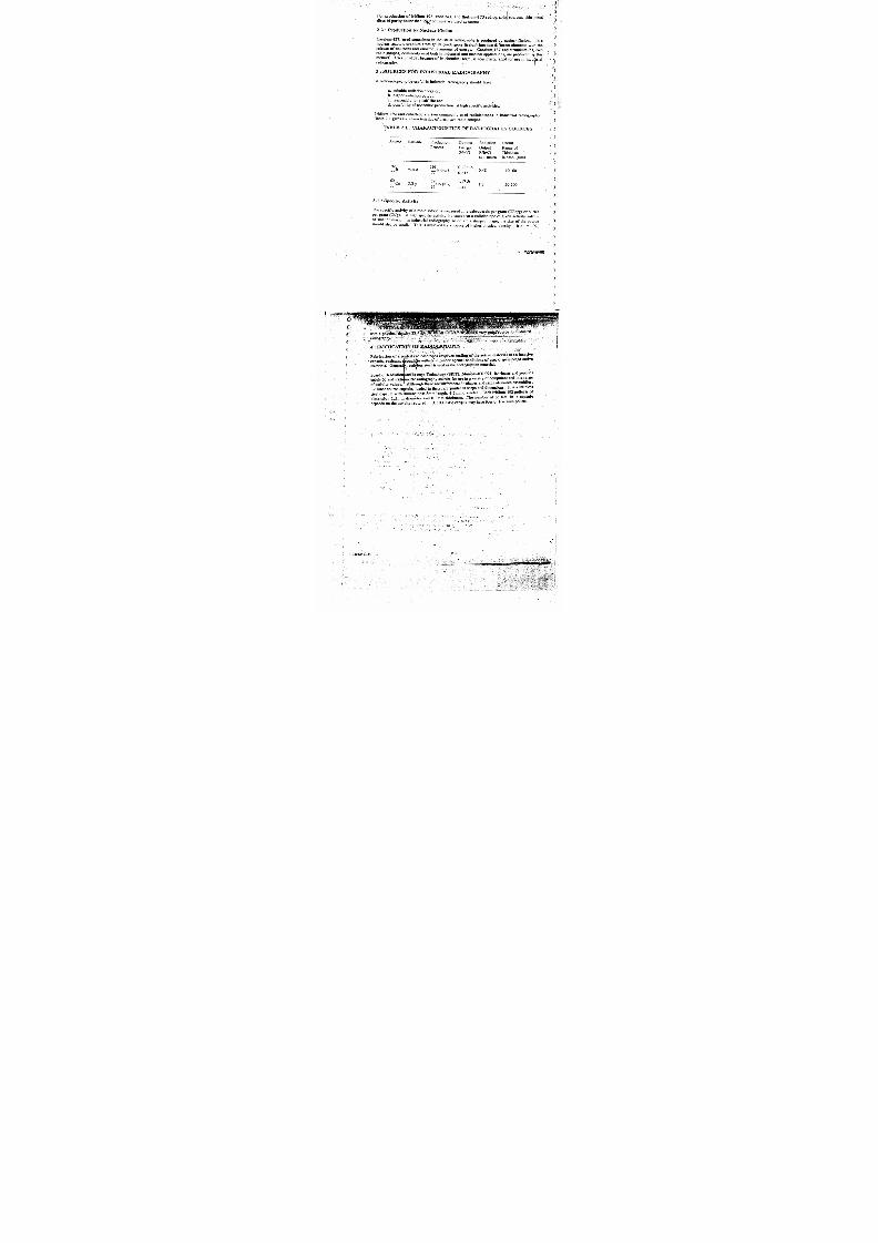
Iridium- 192 and cobalt -60 are two commonly used radioisotopes in industrial radiography.Table 2.1 gives the characteristics of then; tio radioisotopes.
TABLE 2.1: CHARACTERISTICS OF RADIOGRAPHY SOURCES
Source Half-life Production
Process
Gamma
Energy .
(MeV)
Radiation
Output
R/h/Ci
at 1 metre
Useful
Range of
This:kness
in Steel (mm)
192 I 19 1 0.296 tor
7774.4 d Ir7 (n,r)
0.6130.43 10- 60
60 Co 5.3 y 59 C o (n ,r )1.17 &
1 . 3 50-20027 27 1.33
3.1 : Specific Activity
The specific activity of a radioisotope is measured in gigabequerels per gram (GBq/g) or curies
per gram (Ci/g). A high specific activity indicates that a radioisotope of given activity will be
of smaller mass. In industrial radiography, to obtain a sharper image, the size 'of the source
should also be small. This is achieved by a source of higher physical density. Iridium-192,
2,7
l

7/22/2019 BARC RT LEVEL II.PDF
http://slidepdf.com/reader/full/barc-rt-level-iipdf 25/160
C
with a physical density .2 ..4 g
radiography...
4 : FABRICATION OF R PYOISOTOPES
Fabrication of a sealed. radioisotopes involves sealing' of the active material in-an'inactive
capsule, resistant ^voughltowithstandunder nprmal-conditions of use, dispersion ; of active
materials : General y, stainless steel is used as the encapsulation material.
Board of Radiation and * Is xtope Technology (BR IT), Mumbai-400 094, fabricates and supplies
cobalt -60 and iridi in-192 radiography sources for use in a variety of.equipment and in a range
of activity values. Although there are differences in shapes and sizes of source assemblies,
the inner source capsule , loaded in these , are similar in shape and dimensions. It is a stai nless
steel capsule with dimensions: 8mm length, 4.5mm diameter... Eacharidium-192'pellet is of
dimension 2.5mm diameter and 0.3mm thickness. The number, of pellets in a capsule
depends on the activity required. A 1000 GBq capsule may have fdur.,or five such pellets.

7/22/2019 BARC RT LEVEL II.PDF
http://slidepdf.com/reader/full/barc-rt-level-iipdf 26/160
TABLE. 2.2 DECAY CHART FOR COBALT-60 SOURCE'(Half-life: 5.27 years)'
Months-> 02 08 1 0
Years
00 -.. y
0 . 9 8 0 . 9 6 0.94 0 . 9 2 0 . 9 00 1 . 0 . 8 8 0 . 8 6 0 . 8 4 0 . 8 2 0 , 8 0 0.780 2 0.76 0 . 7 5 0 . 7 3 0 . 7 2 0 . 7 0 0.690 3 0 . 6 7 0 . 6 6 0 . 6 4 0.63 O . 6 1 0 . 6 00 4 0.58 0 .5 7 0.56 0.55 0.54 0.530 5 0.51 0.50 0.49 0 . 4 8 0 . 4 7 0.4606 0 . 4 5 0 . 4 4 0 . 4 3 0.42 0.41 0.400 7 0.39 0 . 3 8 0 . 3 8 0.37 0.36 0 . 3 50 8 0.34 0.34. 0.33 0.32 0 . 3 2 0.310 9 0.30 0 .29.0.29 0.28 M28 0.271 0 0 . 2 6
0,26 0.25 0.24 0,24 0.24
TABLE 2.3 : DECAY-'C- ILART FOR IRIDIUM-192 SOURCE
(Half-life ; 74.5 days)
Days 0 5 10 15 20 2 5 3 0 3 5 4 0 4 5
000 - 0 . 9 5 0 . 9 1 0 . 8 7 0 , 8 3 0.79 0 _ ' x ` 5 0.72 0.69 0.66050 0.63 0.60 0.57- 0.54 0.52 0.50 0--7 0.45 0.43 0.41100 0 . 3 9 . 0 . 3 7 0.36 0.34 0.32 0.31 0 . 3 28 0 . 2 7 0 . 2 6
150 0 . 2 5 0 . 2 3 0,22 0 . 2 1 0.20 0 . 1 9 0 . (.18 0 . 1 7 0.16
20 0 0 . 1 5 ' 0 . 1 5 0 . 1 4 • 0 . 1 3 0 . 1 3 0 . 1 2 0 . f . 1 I I 0 . 1 1 0 . 1 0
2 . 9

7/22/2019 BARC RT LEVEL II.PDF
http://slidepdf.com/reader/full/barc-rt-level-iipdf 27/160
C
C
J
0
0
0
0
0
8N
t
0
8N
0
00N
00
OL*Z
FnACTUHI (EMAINItIC
o 00
NWan
FIIACTION UIEMAtN11ICN- . °122
0 O 0.
K)
0
0
_ Jr

7/22/2019 BARC RT LEVEL II.PDF
http://slidepdf.com/reader/full/barc-rt-level-iipdf 28/160
2C. G AMMA RADIOG RAPHY EQUIPMENT
1 : INTRODUCTION ,
G amma radiography equipment or camera consists of the fol lowing :
1. A source housing, w hich serves as a shielded container for the gam ma source duringits storage and it has an arrangement to give a controlled radiation beam, when
needed.
2. An 'Exposure Mech anism', built in the source housing or separately attachable and
3. Accessories such as source manipulators, teleflex cable and gear drive system,
,flexible guide tubes for the cable and source travel , source position indicators,
radiation beam collimators , source changers (for transport), etc.
Design and development of radiography equi pment has special importance in the programme of
NDT inspection..
2: DESIGN CRITERIA FOR EXPOSURE DEVICES
The design and test criteria for radiographic exposure devices are based upon both use and
transport considerations , as these devices are also used as transport packages.
Size ,shape and weight of a.radiography camera is dependent upon the types of exposure
mechanism , the act ivi ty of the. radioisotope and also on ` the shielding material used . The heart
of the gamma' adiography ,ezposure device is sourceassembly with its housing. ' 'he design
and fabrication criteria t o be considered are
1. shielding material
2. exposure mechanism
3. source assembly
4 , s a f e t y i n t e r l o c k s
5 . c o n t r o l u n i t
6. accessories
7. feasibility and reliability
8. easy maintenance and- source replenishment
9. installation
10. transportation
In general ,the exposure devices can be. broadly classified on the basis of their weight.
30
a) Manually handled (light) - upto 50 kg (Class P) (Portable)
b) 'Holley mounted (medium) 50-500 kg (Cass M) (Mobile)
c) Nixed (Inhouse) '(Heavy). - Over 500 kg (Class F) (Fxed)
Trolley and manually handled units can be moved at the site for exposures . Classifications
given in brack ets are as per ISO 3999.
I2.11

7/22/2019 BARC RT LEVEL II.PDF
http://slidepdf.com/reader/full/barc-rt-level-iipdf 29/160
(
----- 0e , f i i i , n74
1. Main body 2. Source 3. Source assembly.
4. Shutter 5. Teleflex cable 6. Driving unit
Fig. 2.5 : Source Exposure Methods.
a) Source held - in the housing and the shutter is displaced to expose the source(Fig; 2.5a).. . It could be used 'only. in portable cameras because of practicall imitations on size and weight of th e shutter . (no longer in use in Indic)
b) Source held on a cylindrical drum w hich is rotated to expose the. source - ( Fig. 2.5b).
It provides wide radiation beam.
c) Source enclosed in a rig id source holder which is moved t hrough a small distance-forgiving th e exposure (Fig..2.5c).. This type is used generally for sources with m ore-penetrating radiation such as cobalt-60, of : higher activity , and for use in permanentexposure rooms.
d) Source : as ombly at tached to the`t ipof a-flezible cable and-driven out of the sourcehousing for panoramic exposure (Fig. 2.5d).

7/22/2019 BARC RT LEVEL II.PDF
http://slidepdf.com/reader/full/barc-rt-level-iipdf 30/160
3: DESIG N
The impprtant points to be considered, whip designing a radiography camera are ;
1. type of source assembly,.
2. shielding material,
3. source exposure mechanism,
devices,. incorporation of safety
5. feasibility of fabrication,
6. easy maintenance and sou ^ ice reply:nishment
7 . installation and
8. transportation.
3.1 : Source Assembly
The radiation source in a radiography camera is always housed in a secondary. container called
'source assembly '. The source assembly can be of two types, rigid or flexible . Rigid source
holder is preferred for source housings shown in fig . 2.5a to 2.5c. Flexible source assembly is
:used , when the source ,is required to travel large distance to and from the source housing,through b ends and at different planes . (Fig 2.6)
Iridium-192pellet .
ROLI- 1 source assembly
Source capsule,
v77`7'.17.1. 1. 7°77`
Tecliop5-660 source assemblg-
\ \
Teletron source assemblg
Fig. 2.6 : Source Assemblies
3 . 2 : S h i e l d i n g M a t e r i a l
As stated earlier, size and weig ht of a source housing is decided by-theshielding m aterial and its
thickness . Properties of different shielding mat erials are given Table 2.4.
2.13

7/22/2019 BARC RT LEVEL II.PDF
http://slidepdf.com/reader/full/barc-rt-level-iipdf 31/160
1. Atomic number 82 88% tungsten (Z=?4) 92
9% copper (29)3 % nickel (28)
2. Densi ty in gram /cc 1131891907
3. Melting point (°C 32734201132
5. Half value layer
C obal t -60 (mm ) 12.45 7.65 6,88
Iridium- 192 (mm ) 4.8 3.2 2.71
L ead is a commonly used shielding material , as it is cheaper , easily available and can be made in
any desired shape . But, it needs a metal - l ining to hold i t, as i t is a soft material . Heavy alloy and
uranium are best suited for shielding to produce compact and l ight w eight cam eras
. However,
fabrication of source housings with these materials requires special techniques.
3.3 Source Exposure :
Direct ional exposures wit h coll imated beam w ith source f ixed in the source housing are best
from the radiation safety stand point. However, such exposures greatly restrict the flexibili ty
of operation . Therefore , most of t he modern units are designed for panoramic exposure with,
provisions to attach collimators (Fig. 2.7) for directional exposures...
For circumfe -ential exposure For unidirectional exposure
T i.
Shielding' thi ckness should be more than 1 TVL
Fig. 2.7 : Col limators°
2.14
r'l ti r

7/22/2019 BARC RT LEVEL II.PDF
http://slidepdf.com/reader/full/barc-rt-level-iipdf 32/160
Panoramic ex posures are made by m oving th e source assembly out of thesource housing usingremote driving devices, operated by pneumatic , electrical or mechanical systems. With flexiblesource assembly , only mechanical system s using teleflex cable are favoured.
3.4 :Safety Devices
All radiography equipment should be provided with safety devices such as inu :rlocks, source.couplings source holder locking, immobilizing device for the source , etc. In-house facilities
are planned with more elaborate safety devices, such' as door interlocks, audio - visual' signals,search-operatiotas .in exposure areas, and other fool-proof safety features . In.addiFion,radiation m3Tnitoring instruments should also be, incorporated in the design.
3.5 : Fabrication
Design of the unit should be done keeping in mind the limitations during the fabrication ofcomponents . These components are evaluated .for soundness and reliability to ensure fool -proof performance over the designed life of the equipment.
3.6 : Maintenance
The equipment should be designed in such a way that mi nimum maint enance is required duringits service and.defective part i s easily replaceable.
3.7 : Transportation
The design of the camera , when loaded with source should meet the < prescribed transportregulations.
3.8 : Installation
Installation of units with kilocurie activity needs special gadgets. These gadgets should be
designed in conjunct ion wi th the uni t t o be instal led.
TABLE 2.5:: PERMISSIBLE LEAKAGE LEVEL
AROUND RADIOGRAPH' CAMERAS
Maximum exposure rate
mGy/h (,-.,PJH)
Class On external 50mm fromsurface of external surfacecontainer of container
Portable 2.0 (200) or 0.5 (50)
Mobile 2.0 (200) or 1.0 (100)
Fixed 2.0 (200) or 1.0 (100)
2.15
1 r t t ;
extern2.s sseof con: -_ae
0.02 {
0.05 t i .
0.10 (1

7/22/2019 BARC RT LEVEL II.PDF
http://slidepdf.com/reader/full/barc-rt-level-iipdf 33/160
QUALITY CONTROL DURING PROUI^CTIO^T:
All radiography cameras are .required to be sublet ed to strict g t,alrty^control examinatior. to
confirm the Integrity ofmechanical parts and also to ensure that radi ation leakag e levels are
below t he permiss ible limits. The existing permissible radiation . leakage. levels on t he sourcehousings in 'off position are given in..the table 2.5.
ns to ssess the life of components and associated accessories.
Prototype lu nits x' i th remote control system are specially tested for. operational reliability under
simulated nditie a
5: EQU PMENT IN USE IN INDIA
er wt ead, heavy alloy or depleted uranium
1. Portable
Iridium-192 and cobalt - 60' sources together can cover an inspection range of thickness
10-200 mm, steel equivalent. Thus, efforts. for equipment development have been mainly
directed towards these sources. Many equipment are commercially available, with these; + Uources shielded eith
Teletron SU-100/50 Gammamat TI/TI-F/S-301Amertest-660 ^,, Century SASpec-2T20G ammarid
2. Mobila
RCOLI-1 Gammamat-M(Crawler)
CRC-2A, Gammamat TK 10•
IRCX150 GR-50
Fri&d
CBC 5000 Gammamat TK 100/600Amertesi 520 Gas Prom
Some of these egilipment are discussed below.
54 Lead shielded, low cost equipment
5.1.1: Iridium-192 Units'
ROLL-I is a remote operated lead shielded cainera'designed for 35 Ci iridium-192 source
(Fig. 2.8). It has 'S' conduit to-house a flexible source assembly.
5.1.2: Cobalt-60 Units
Radiography camera with a capacity of 10 Ci designed for panoramic exposure is shown in

7/22/2019 BARC RT LEVEL II.PDF
http://slidepdf.com/reader/full/barc-rt-level-iipdf 34/160
figure 2.9. The spherical source h)usini, s mounted on a rugged trolley for ease ofaneuver .
The unit enables source movement in. a rigid guide tube for panoramic exposure.
Radiation beam can be restricted for directional exposures using a collimator, which can befixed to the source housing.
5.2 : Light. Weight, High ActivityEquipment
These have either depleted uranium orr heavy alloy material for shielding. Fabrication of these
source. housings is not as easy lead ource housings. The cost of the material is also very high.
Some of the imported radiogr, phy eauip;:nent approved in Idi1 n4 . a are shown in figures 2.10 to
6: TYPE APPROVAL OF GA1 J 4 RADIOGRAPHY EQUIPMENT
.The built-in safety of gamma radiography equipment, both from radiation and operational point
of view,, is very essential because majority of the radiography work is carries out in workshopand construction
-sites which call for a strong and rugged equipment. kshop
As per the present safety requirements, in addition to shielding adequacy, all models ofradiography
equipment must be so designed, as to withstand various mechanica l and operationalests , such as
drop test, fire test., vibration. test, shock test, waterimmersion test and endurance
es t, as per the specifications laid down by Inter
national Standards. Organisation (ISO 3999).Only those :equipmnt which conform to all the provisions of ISO 309e
ar approved andermitted to be used for industrial radiography work.
2.17
t

7/22/2019 BARC RT LEVEL II.PDF
http://slidepdf.com/reader/full/barc-rt-level-iipdf 35/160
l
1. Source assembly 2.' Source 3. Lead Shield4. Locking system 5 . Secondary container
Portable/mobile camera Flexible source assembly
Flexible guide tube 'S '. codduit
Ball & socket-coupline . . _ _
Fig. 2.8 : ROLI- 1 Camera
1. Source position
2. Source assembly
3. Rotating shutter
4 . L e a d s h i e l d
5. Shutter handle
6. Shutter arrestor plug
7.'Shipping cap
8. Front side cover
9. Rear side cover

7/22/2019 BARC RT LEVEL II.PDF
http://slidepdf.com/reader/full/barc-rt-level-iipdf 36/160
1 . S h i e l d -
2 . S o u r c e
3. Source assembly
4.- Source assembly catch
5. Key lock for shutter
6. Shutter opening handle7. Spring lock for shutter
8.'.Shielding plug
Portable'camera ,Depleted uranium shield
Rigid source assembly Ball & socket coupling(tungsten) Straight conduit
Fig.. 2.10: Teletron/Gammavolt Camera
--1. Source ._ . .
2. Lock
3. Source assembly
4. Stopper
5. Shield
Portable camera Depleted uranium shield'S' conduit .
Flexible guide tube
Ball & socket coupling Flexible source assembly
Fig. 2.11: TechOps/Amertest Camera
2.19

7/22/2019 BARC RT LEVEL II.PDF
http://slidepdf.com/reader/full/barc-rt-level-iipdf 37/160
1. Source . capsule . 4. Source assembly
2. Safety plug ;, L^F;.,1 5:lunger type lock=.. ;=;,,_.- - :.mac
- 3. Depleted uranium-shield '=
Fig. 2.12: SPEC - 2T Camera.
1. Source assembly
2. Source
3. Shield
4. Shutter
Portable camera Depleted uranium shield
Flexible pencil Straight conduit
Flexible guide tube Ball & socket coupling
Fig. 2:13 : G ammamat Camerai

7/22/2019 BARC RT LEVEL II.PDF
http://slidepdf.com/reader/full/barc-rt-level-iipdf 38/160
1. Shutter plug in a hollow shuttle 2. Shutter arrestor3. Shutter shuttle receptor 4. Source capsule5 Sourceholder 6Shield 7. Lock
Fig. 2.14: Gammarid - 192 Camera.
2.21

7/22/2019 BARC RT LEVEL II.PDF
http://slidepdf.com/reader/full/barc-rt-level-iipdf 39/160
C
3A. pH .:TOGRAPx-HC AND, NON-PHOTOGRAPHIC
-RECORDING
1: INTRODUCTION
(
The type of X-ray - film used in radiography , plays an important role din th e detection of flaws.It is therefc re, important t o have detailed knowledge about struct ure and properties of films.
2 : STRIACTURE OF X -RAY FIL M
F i g u r e 3 . 1 howl .xoss-section of a typical X -ray film . It consists of
base,
emulsion, .
binding layer and
protective layer
Protective layer (11A)
Emulsion ( 10 - 15 1 A )
Polyester-Base (175µ)
Emulsion (10 151 A )
'Protective layer (11A)
GFig. 3.1 : Cross Section of an X-ray Film
2.1 : Film Base
Polyester is the most commonly used material for film base.
2.2 : Emulsion
Silver bromide (AgBr) mixed w ith. gelatin, is used as film emulsion.
2.3 : Binding layer
This layer acts as binder between film base ' and emulsion.
2.4 : Protective layer
The protective layer consists only gelatine.
damage, abrasion and stress marks.
It serves to protect t he lower layers from physical
3.1

7/22/2019 BARC RT LEVEL II.PDF
http://slidepdf.com/reader/full/barc-rt-level-iipdf 40/160
3: CHARACTERISTICS OF FILMS
3.1 : Film Density
X-rayfilm on exposure to radiation and processing produces black deposits of silver. 1
blackening of th e film is called optical density (D) and is given by t he expression,
LD = Loges
Where L0 = Intensity of inc ident l ight
LL = Intensity of transmitted light
Opticaldensity is measured with an instrument called 'Densitometer'.
The factors which control the optical density are
a. type of film
b: energy of radiation
c. amount of exposure and
d. processing conditi ons
023
Log relative exposure -^
Fig. 3.2 : Characteristic C urves of X-ray Films
3.2 : Characteristic Curve
If:, number of different exposures are given to various areas of an X-ray film and densities
obtained at these areas after processing are plotted as a function ofLogo (exposure), the
3.2
ewr4wagme

7/22/2019 BARC RT LEVEL II.PDF
http://slidepdf.com/reader/full/barc-rt-level-iipdf 41/160
resulting c u r v e is called ' Characterist ic ; ;urye , of thed-Win (1.1g.. 2}.
(
( .
onioniv: s informa
a. speed of film and
b. film contrast
3.2.1 Speed
Speed is defined as the density recorded on a film due to a given radiation exposure. It is
measured in terms of inverse' of exposure . requir ed to produce a radiograph of a particular
density , under given conditions . Keeping other factors constant , a film which requires less
exposure is faster . Figure 3 . 2 show s character ist ic ,, of two industrial X-ray films in which
film A is faster than, film B.
TABLE 3.1 : FILM FACTORS OF SOME COMMON FILMS
Source Type of ' Film Film Factorwith DoubleL ead Screen
Iridium-192 . Agfa D-2 9.5 RD440R
D712R
-NDT-55 .. 3.8R
*NDT --65 1.4 R
NDT --70 1.0 R
Source Type of Film . Film Factorwith DoubleL ead Screen
Cobalt-60 . Agfa D-2 196R
'D80R
D=725R
NDT-5575R
NDT-653OR
NDT-702OR
The amount of exposure of a given radiation energy required on a film t o produce a given film
density (usually. 2.0) under specified condit ions of processing is called ' film factor'. A film
with lower film factor is faster than the one with a higher value . . Film factor depends on
energy of radiation .Film factor values fora few com monly used films are given in Tab le 3.1.
3.2.2 Contrast
Film contrast or gradi ent is defined as the•.change in density recorded on a. film for a given
change in radiation intensity.
The slope of the characteristic curve at a given density is the measure of the gradient of the
film, Gd, at that density,
D2 D1L og E2 - L og
3.3

7/22/2019 BARC RT LEVEL II.PDF
http://slidepdf.com/reader/full/barc-rt-level-iipdf 42/160
The gradient of a film depends on the size of its crystals . • G radient of industrial X - ray filmsgoes on increasing with optical density , as shown in figure 33. it is practicall inde nd e n tpof the radiation energy. In general , compared to coarse grain film fine grain films have lowerspeeds , but , h igher gradient at a g iven densi ty .
123
Density --7
Film Speed
H>Y>Z
Fig. 3.3 . 'G radient Versus Density
3.3 : Effect of 'radiation energy
There is very little effect on the shape of the characteristic curve due to energy of radiation.. How ever, the film speed depends on radiation energy , as can be seen in table 3.1.
3.4 Various Types of Films
The films can be divided into three groups on the basis of radiography requirements.
1. Films for use with fluorescent screens, also known as salt screen films.
2. Films for use w ith met al screens or wit hout screens (also called 'direct films'). Thisgroup covers a large range of industrial X-ray films. The films are classifiesdepending upon the grain - size of the films;
Class - I Highest contrast, lowest speed filmClass - H. - High contrast , low speed filmClass - III - Medium contrast, medium speed'film
Class - IV - Lowest contrast, highest speed film
3. Films used for special purposes, e,g, single emulsion films.
3.4

7/22/2019 BARC RT LEVEL II.PDF
http://slidepdf.com/reader/full/barc-rt-level-iipdf 43/160
,r n A» > TT0RFSCENT.SCREENS:
( IC
C
l
1. INTRODUCTION
When an object is radiographed wit hout using screens , there are two disturbing factors.
1. The absorption of primary radiation (transmitted through the object), in film is low.
This results in longer exposure time.
2. The absorption of low energy scattered radiation (scattered by t he object), in film is
relatively more . Thi; reduces the image quality.
Hence , to reduce exposure time and improve image quality of radiographs , radiography screens
are used.
2: TYPES OF RADIOGRAPHY SCREENS
There are two types of radiography screens , commonly used in industrial radiography
practice : meta llic foil screens and fluorescent screens.
These screens differ in their basic characteristics e.g, speed , contrast and elimination of scattered
radiation.
3: METALLIC FOIL SCREENS
Metallic screens help in reduction of scattered radiation from the object. The X-ray film is
sandwi ched- between ; a pair .of lead . screens, as shown i n figure 3:4.
V1I
......•::.:r:: ^:;. ::asp
\1l \T/\`^.\`^
Radiation transmittedi from object
Card board I plastic
=- I ead-screen (front)
- Film
L e a d s c r e e n ( b a c k )
Card board / plastic
Backscattered radiation
Fig. 3.4 : X-ray Film Sandwiched Between a Pair of Lead Intensifying Screens.
3.5

7/22/2019 BARC RT LEVEL II.PDF
http://slidepdf.com/reader/full/barc-rt-level-iipdf 44/160
3.1 : Reduction of scattered radiation
Attenuation of incident radiation in the object results l
o wroduction of°
W)
radiation and t his falls on the film, along with the in ut energy scar .^
atomc numberel transmdments have more absorp tion capenergrimay ry radiations
radiation. rfaAs : loil of highatomic number
is placed bstweeobjectapacity for low
,energy radiation,- before it f and film, it will abl sorb most of theos on the film. Hence, effect of eadiation will be reduced .
This metallic foil will serve additional thu low .enerction also . Similarly, scaty, to reduce low ener
gyf ¢
¢ pose! of e rfica ^ack . scattering:of the itain
pr (° ined dary radiation , fr objectsadiographed ) om l a ope
p aced behi d c fa metal sheet of highatomic number is l e specimen m-, ,double coated X acebray film i thc ' i e
111tH. Hen(,.?ndwiched betw een a pair of metalffec o scateredo
radiation on
sa
the film, r lic if screens raditoreduce(exultingin an improved defrnit ion of radiogra,,
3.2 ; Intensif in A >g ctinn _
Intensifying act ion of a radiograp h
y which is defined as screen is expressed in terms of rnrensificatiOn Factor (u
Exposure t ime required to produce a certainIF = film density without screen
Exposure-time required topwth screen . roduceam e density
In this definition ,it is assumed that same film avid radiation source are
exposures. 'IF' due to double lead screen exposure with action -192 used for both tfx
source is about 4.5.,
Intensification action occurs due to the photoelectrons, emitted as a resultof interactionrays with the material.
of X o(
Intensification factor due to metallic screens depends
on:
a. foil element
b. thickness of foil,
c, energy of radiation, andd. 'pecimen thickness.
4 : FLUORESCENT SCREENS
These are also called 'Salt Screens'.
materion which certain inorganic crystalline s
hese screens consist of
a u b s t a n c e s a r e c o a t e d o n o n e s i d e . T h e y g l o wlight when radiation is incident oil them. Since a photographic film
card is board
more orsensitive
plastic givir:
t i v v e t o g i ! i g
than to X/r rays, it enhances the sensitivity of the film. A material which has e its figemission in blue or ultraviolet region IS used ,-
g'to blue tight. The for t,ti-s Purpose, since the film is highly sensiti
most commonly used material for this purpose is calcium tungstate. Thescreens are used in pairs, so that a double coated X•ray
as shown in figure 3.5. film can be sand-witched between the
3.6
^Viwm

7/22/2019 BARC RT LEVEL II.PDF
http://slidepdf.com/reader/full/barc-rt-level-iipdf 45/160
C,F.*- yv ' -yew
C :
( i
- X or gamma rays
-Card board / plastic
-Salt (CaWO4) screen
- Film
- Salt (CaW O4) screen
-Card J,oard / plastic
Fig. 3 . 5 X-ray F i lm sandwiched betw een a pair of salt intensify ing screens
3.7
unsharpness.
Each._crystal.. in salt screen emits l ight . This light'ldiiverges in all directions and gives imag e
Intensification factor (IF) due'ta salt screens depends upon
a.; density of radiograph,
bJ thickness of screen,
c.; coating material and
d. energy of radiation
InIgamina 'radiography, ° the-,intensification factors with salt screens , are not very much -greater
than that 'obtained with lead screens . Secondly, th ese screens give poor quality image . Hence,
these screens are not'much used in industrial radiography.
I H . . 1 l l l b l

7/22/2019 BARC RT LEVEL II.PDF
http://slidepdf.com/reader/full/barc-rt-level-iipdf 46/160
4A. WORK PARAMETERS AND CONDITIONS
1: INTRODUCTION
In' radiography, work parameters and conditions play an equally im ortant role has t e applic^ .radiography techniques. The handling of X-ray films before and after exposure and filr>processing are important in th is respect.
2: HANDLING OF FILMS
X-ray films should be handled ' carefully to avoid physical strains such as pressure creasing.
buckling and friction on it. The normal pressure applied on a cassette to provide goodcontat.
with the object does not damage the films. Whenever the films are - loaded in flexible cassette"and external clamping devices are used , it should be seen that pressure is applied uniformly.L ocalized pressure on film can duro ce artifacts in t he radiograph
2.1 : Loading and Unloading Films
Films should be held by edges in order to prevent finger or pressure marls P i trecaut on shou
be taken to avoid handling films in a manner which would cause frictio1 and give confusing:black marks on the radio hrap .
2.2 : Expiry Date
The expiry date pn a . film pacts means that the film should be used before the given date.Ex p i ry dates ol'die films : tepeitd oit i T i e storage conditions.
3: FILM STORAGE
3.1 : Protection from Gamma and X-rays
X-ray film should be protected from X - rays and gamma rays to avoid fogging.
3.2 : Chemical and Physical Hazards
Film should not be kept in a chemical storage room or in any loca'io- where there is leakageof gas . Chemical vapours , high humidity and temperatures also cc :_:-ibute to film fogging.
Film should be stored in as cool a place as possible , and in tropi :< regions, temperaturescontrol in the store r oom is recommended . Films may be stored for long periods in arefrigerator.
4-: FILM PROCESSING
After exposure to radiation, a latent 'image of the object is form, i y the X,ray film. Film: r0CCSSi ^b_
i iv B.ible hiiagt to a visible . and permanent image . There are f ivemain stages involved in film processing
. S-i h„
4.1

7/22/2019 BARC RT LEVEL II.PDF
http://slidepdf.com/reader/full/barc-rt-level-iipdf 47/160
1. Development oreation of the visible . image.
2. Stop bath removal of excess developer solution and stopping of developingaction.
2. Fixation : removal of unwanted, unexposed silver halide and making image
permanent.
3. Washing : removal of unwanted fixation products.
4. Drying removal of . unwantedwater.
5: L ATENT IMAG E FORMATION •
On exposure to X or gamma radiation , silver bromide in the film is converted to metallic
silver.
6 : EFFECT OF DEVEL OPMENT
The function c•f developer solution is to reduce only exposed grains of silver bromide into
additional metallic silver and leave unexposed , unaffected grains . The rate of development of
exposed crystals is much greater than corresponding rate of unexposed crystals.
Mechanism of the reaction is
c
(
(
1. Solid pack , containing two separate bags of chemicals which have to be dissolved in
correct quantity of water before use.
2. Liquid concentrate, which require appropriate dilution with water to give the
working solution:
6:1.1 Coaunercial Developers lx'c. AGo 3Au/
Some of the commercially available developers for manual processing of X-ray films are given
in Table 4.1.
Ag+ + e: ---> Ag
The electron for the reaction is donated by developer solution.
6.1 : Developers in Use
erss of develo n'( ristinct th tw . ,p a_re are o
V % v t 1V(471A
AN-
.6.1.2: Use - of Developers
ideal developing t emperature is 200 C and duration of 5 minutes.
developing , it should be properly agitated during developing.
4.2
To avoid faults during

7/22/2019 BARC RT LEVEL II.PDF
http://slidepdf.com/reader/full/barc-rt-level-iipdf 48/160
MakeTrade Name
Size of the packto make (in litresof working solutionKodak Indian
PhotographicCo developer
Agfa-Gaevert C-230
Ma & B
2.254.509.00
13.5022.50
developer 2.254.50
9 . 0 0
13.50
22.50y aker Solidex X-ray
Developer 2504.50
9.0013.50
22.50
*7 :STOP BAjj. .
After developing, the image comes
and enable to be viewed, into existence and remaining osses makes it PermarIfenhan no. action. is taken, the developer will continue to' work product..,,
ced densfty, fog or irregular developer stains. The unwanted developer
a stop bath. There are two types of stop baths. is removed uy
7.1; Water Rinse
The excess developer is removed from the film simply by inmersin1, it •
bath.. Static water rinse involves the risk of solution becoming alkaline in a running wa-
be of any use in stopping development. Hence, running water bath i oith use and cease tnrec
-72AceticAcidRnse mmended
This; bath is static and 2 to 3
effigy;ietit in action and requiresf films to be immersed a neit for bout5 m to ed
seconds . with agitation:owever, unlike flow water rinse, acetic acid wll become c P y This is more
throughput of 100 FT2/gallon is reasonable life suggested for this
.exhausted with use. A
7.3 Faults arising during rinsing.
Th only fault which can occur at this stage is due to delay in puffin'
nhs top bath. A thin layer of oxidized developer on the film can lead developer laden
to production of browsw n
4.3

7/22/2019 BARC RT LEVEL II.PDF
http://slidepdf.com/reader/full/barc-rt-level-iipdf 49/160
'.ty.'"w t rla ult: Cd . . 3rtll J
w w11 w. yi.
8: FLING BATH
8 1 • Filing Agent Iand so will slowly dark en . if it is al?lowed io•remain on the film.
The fixer reacts with undeveloped silver bromide in the film and transforms it into water.
soluble compound which gets dissolved ' in washing operation. In addition , it enables the
image t o become.permanent . Since the silver halide is st ill sensit ive to . l ight to a small extent ,
N3
..he most w idely used agent is sodium thiosulphate (Na2S2Og), commonly known as 'h pot
Its solution in Wat er rapidly dissolves silver chloride and bromide . uAc- A-dd IV4 ,
8.2 : Use of ]Turing Bath
Generally, the film is kept for 2-3 minutes in rapid fixing bath and for about 10 minutes in
ordinary hypo bath.
1. Agitation The fi lms should be agitat ed initially , w hen immersed in fixer.
2 . Temp erature . The fixation process is less critical than development processand a temperature range oft 2.5°C to standard 20°C is
acceptable.
8.3': Faults arising due to fixation
Most of the defects arise clue to contamination of fixer by developer into fixer , through
careless use of stop bath stag e. Faults may also arise if films are inserted w ithou t agit ation.
Streaks may b e produced , due to uneven removal of developer.
9 . : WASHING. .AND DRYING
0.1': Washing
Washing is carried out to eliminate unwanted products from the emulsion after the fixing
operation. For this purpose, . the film is washed in running water for about 20 minutes and
then taken for drying. It is important to ^ use' flowing water , so-that the film on its removal
frombath is•taken out fromuncontaminated water. -
9.1.1 Faults arising during washing
Usually t wenty minutes are allotted for th is stage, but the period may prove insufficient if ,
a. the w ater is unusually cold,
b.'flow is inadequate,
c. tank is too. small for film throug hput and
d. film is not inserted ` n a proper way.
4.4

7/22/2019 BARC RT LEVEL II.PDF
http://slidepdf.com/reader/full/barc-rt-level-iipdf 50/160
Each of these factors will lead to incomplete elimination of thiosulphate complexes from
gelatin . This will make the film yellow/brown on storage.
9.2 : Drying
It is necessary to remove excess water, as a wet radiograph is not convenient to handle and is
liable to mechanical, damage. Usually the wet films are dried by blowing a current of hot aif
over the films, and various types of drying cabinets exist for this purpose.. These cabinets
often include filter at their air intake to free the air from dust, which may stick to the wet film.
10: CHECK LIST OF PROCESSING -DIFFICULTIESAND FILM BLEMISHES
Blemish or Difficulty
Black crescents
White crescents- .
Black streaks / blotches
Streaks
,/Drying spots and
streaks
-Black spots
Brown stains
Dark deposits
White crystalline
deposits
Milky appearance
Sharply outlinedlight dark areas
Blisters
Air bubbles
( l ight spots /patches)
Causes
Kinking of f! m b efore processing.
Sharp bending or folding of the processed film.
Over-development, over-age film, prolonged exposure to safe light,
improper safelight filter, insufficient protection in storage from
radiation sources, film stored where temperature or humidity is toohigh or chemical vapours exist, viewing developed film, before it is
properly fixed.
Light leaks due to faulty film holders or cassette.
White and black streaks at points where film was attached to hanger
caused by processing solution remaining-on clips from earlier use.Inadequate agitation during development. Removing film to viewduring development time causing developer to run across filmunevenly. Contamination by chemically active deposits,contamination of developer / fixer.
Drops of water on semi-dried film or drops of water runningdown semi-dried surface.
Developer splashes before placing entire film in developer.
Inadequate fixing.or exhausted fixing solution, prolonged
development in old developer, inadequate rinsing.
Oxidized products from developer or reacting silver salts.
Inadequate washing after processing.
Incomplete fixing, exhausted fixing bath.
Uneven development, films not agitated during development,films, hung too close together in developer.
Formation of gas bubbles in film emulsion.
Air trapped on film surface during development.
4.5
I

7/22/2019 BARC RT LEVEL II.PDF
http://slidepdf.com/reader/full/barc-rt-level-iipdf 51/160
Reticulation ( leather
like appearance)
Frilling ( loosbning
of emulsion)
Static mark s (Blackbirdtrack effects)
Scratches (black,
crack- like lines),
"Dark fingerprints
"sight fingerprints
White spots and'areas
Britt le radiographs
Solution too warm , extreme-d ifferences - in temperature of
successive processing baths.
Fixing in warm or exhausted bath.Prolonged w ashing at high t emperature.
Due to'static electric discharges caused friction betw een fi lm and
some other object.
Improper handling.
Film touched .wit h dirty fingers before development.
Film touched w ith g reasy fingers before. development.
f i t ted or w orn screens . Dirt on film screens.
Excessive hardening in fixer.
Excessive drying t ime.
overned mainly by the'basic principles,of the shadow
The radiographic image on the film is g controlling various geometricalfo.mation. - A sharp aid undistorted image is obtained. by offactors such as source size, source to film distance, film to abject distanc , alignmentexposure
-`radiation beam. with respect to the plane of the object and film. Different
geometries are shown in Fig. 4.1
romthese exposure. eometries, it could be seen thatthe radiographic images always have anF
element of magnification which will depend upon-th
e Ioseness
planes of t elobject athed h°tfilm`en of oddDistortion in the image would depend on the
Attempts are mrmade to keep both of them in the same plane, however, with specim
.geometry image. distortions are observed.
on the radiogralih due to the finite size
Both X and gamm a rays produce a. certain unsharpHesseomet; ical unsharpness (Ut)
of the focal spot`oc`tlie source.: This unsharpness is called g
which is calculated.as..: , ,
11 : G EOMETRYOF IMAGE FORMATION
dx .- orSFD = t(l+d/Ut
us SFD- t . .
c-t
t i is blear from this ex p ression, that U can never be zero .The magnitude of Ut can uii iy
proper selection of exposure v ariables . Considering• this,:fact , various codes
minimizedby proppermit a cert ain Ug value related to object t hicknesses..
kness of the object.hi
SFD - source to .film distance, . -
where, d -effective diameter of the source/focal spot,

7/22/2019 BARC RT LEVEL II.PDF
http://slidepdf.com/reader/full/barc-rt-level-iipdf 52/160
TC:
I .
V N E W I N I X I M E M E N / I
Small sourceSmall U9
C
A / / r / / / / % r . 7 / / / I d ^ / f / f i l 1
11 Large source
Ug Large Ug
$
II1
Thinner object Thicker ob ject
Small Ug Large Ug
1
C
Central axis Central axis notperpendicular to perpendicular to
object centre object centreSmall Ug Large Ug
Large SFDSmall Ug
Film close to
object F
Small Ug
^ 9I/f I / I /7 IJ0UlUf l f / ,
Film awag fromobject-Large Ug
S - Source, 0 - Object
F -. Film, Ug- Unsharpness
C - Central radiation beam axis
Fig. 4 .1 : G eometric Representat ion of Radiographic Image.
4.7

7/22/2019 BARC RT LEVEL II.PDF
http://slidepdf.com/reader/full/barc-rt-level-iipdf 53/160
Radiation .. X-ray _
Material : See :=
Film: DuPont NDT 65
Film Density : 2.0
Distance : 36 inchesScreens : Lead
Front 0.12 mm
Back : 0.25 mm
Development : 5 minutes20°C
Fig. 4.2 : Exposure Chart for X-rays:C
SAW -_9y 1ti
C C -- `1 '-_ -
0.000
U A W
600-
- -
- -
^.
- -4 0 0300
200- -- -
$ 0 06 o
40rl-
30
20 71 !
0.6
Fig. 4.3 : Exposure Chart for Iridium-
4.8
Radiation : Iridium-192
gamma rays
Material : Steel
Film .: DuPont ND T 35-75
Film Density 2.0
Distance - : 24 inchesS c r e e n s Lead
F r o n t . : 0.12 mm
Back : 0.25 m m
Development : 5.minutes
20° C
92 Source. (Different Films)

7/22/2019 BARC RT LEVEL II.PDF
http://slidepdf.com/reader/full/barc-rt-level-iipdf 54/160
L ead screen : 0.1 mm front
'0.15 rnm back
Iridium - 192
L ead screen : 0 .15 mm front
0.20 mm back
Cobalt - 60
Densi ty : 2, Developing time : 5 minutes, 20° C
Film : Agfa D7, For NDT - 65 film , multiply . above values by 1.5
To obtain exposure values in G Bq x hour; mult iply above values by 37.
Fig. 4.4 Exposure Chart for Gamma Rays (Different SFD)
Recomm endations for optimum results are -
1. source or focal spot size should be as small as practicable . Ideal source will beipoint source,
2. source to object distance should be as large as possible,
3. the film should be in close contact with object and
4. source location should be-such , that radiation pass normal through object thick ness. I
4.9

7/22/2019 BARC RT LEVEL II.PDF
http://slidepdf.com/reader/full/barc-rt-level-iipdf 55/160
( .
(
(
(
a
1.Calculate the present source - activity in curies (Ci) from the decay charts.
2.Find thickness (cm) of the object.
3.Find HVT (cm) of object material; for the gi ven source , from the HVT tables.
4.Find SFD (cm) for the object thickness.5.Write RHM value (0.5 for iridium - 192 and 1 .33 for cobalt-60)
6.Find film factor (F in Roentgen ) from table 4.2.
TABLE 4.2 : FILM FACTOR (F) VALUES
Film Factor (F)Source
NDT-65 NDT 70 Agfa D-7 Agfa D-4
Iridium-192
Cobalt-60
1.4.R. .
2.8 R
LO R
2.0 R
1.1 R
2.2 R
3.5 R
. 7.0 R
Substitute all these values in the'following formula :
F x 21rrrk x (SFD)2 x 60Exposure time (minutes) . C x RHM.x (100)2
It may be noted.thatfthis formula is not very accurate for higher thicknesses, particularly when
using cobalt-60 source. Exposure charts as given in figures 4.2 - 4.4 are more accurate and
are recommended for use.
z rci e 1 : Calculate the exposure time in minutes for 0.75 inch. thick steel using 180 kV
X-rays. The machine is operated at 5 mA settings.
From figure 4.2, the exposure for 0.75 inch steel at I^J kY is 35 mA.min.
If the machine is operated at 5 mA setting, the exposure time is 35'5 7 minutes.
Exercise Z :.Calculate the exposure time in minutes for 1.5 inch thick steel using NDT 65 film
at 12 inch SFD'to produce optical density 2.0, using iridium-192 source of 8 curies.
From figure 4.3, the exposure time for.1.5 inch steel on NDT 65'film is 250 Ci.min.
The exposure chart is made for.SFD of 24 inch.
EF (curie. min) x di 250 x 122i t Exposure time (mn) _- =7.8mnutes
cxd28x242
For calculating the exposure time, the following steps should be followed :
EF - Exposure factor for SFD dir: - A' i itv :n
d2 New 1,SFD .
4.10

7/22/2019 BARC RT LEVEL II.PDF
http://slidepdf.com/reader/full/barc-rt-level-iipdf 56/160
Ex erc i se 2 : Calculate the exposure t ime, wi th the fol lowing data :
Source - Iridium -192, 10 curies (C = 10)
Steel plate 25 mm thick (x = 25) (HVT or T,4 = 12.5 ,nm)
Film -, NDT-65 (F = 1.4)
Radiography density required = 2.0
Let SFD be 50 cm
Substit uting all these values in formula,
1.4 x 221112.1 x 502 x 60Exposure t ime (min)
10 x 0.5 x 1002
1.4 x 4 x 2500 x 60
5 x 10000
16.8 minutes .
From exposure chart (Fig. 4.2) we can see that for 25mr a steel and SFD 50 cm, we need
around 2 . 8 curie x hour . It means the product of source activity and time in hours should be2.8.
Hence, fora source activity of 2.8 curie, exposure time is 1 hour
for 1.0 curie, exposure time is 2.8 hours
fo: 10 curie, exposure time is 2.8 x 60 x 1/10 = 17 minutes
We can calculate similarly, for other thicknesses also.
4.11
I
C
I

7/22/2019 BARC RT LEVEL II.PDF
http://slidepdf.com/reader/full/barc-rt-level-iipdf 57/160
UATION OF RAD IOG RAPHIC QUALITYEVAL4B.
is assessed by radiographic sensitivit y .The sensitivit y, in turn,
The quality of a radiograph
depends upon factors whichcontrol contrast and definition of the image.
1.1 : Radiographic Sensitivity
referringSensitivity is a general qualitative term no the size ofi and definition of
smallest
detail which can be seen on a radiograph. It is governed by the
image appearing on the radiograph.rt.2: Radiographic Contras
ofRadiographic Contrast is the densi ty difference in tw o areas a radiograph
. It depends upon
Radiog pthe subject contrast and fi lm contrast.
gamma ray intensit ies transmittednsed.2.1 Subject Contrast is defined as the ratio of X or g sintensity
through tw o different areas of a^ec^
It depends upon the radiationn qua li t y,
subject
distribution, and scattered radiation. Higher the radiation energy, lower would be the ns
contrast.
1.2.2: Film Contrast (G) refers to the slope of characteristic curve of the film at a given
rocessing conditions and optical density. It isf film p
.- It depends upon the typeo,density
independent of radiation quality . Mathematically , it can be ex pressed as
D(i = Log E
1.3 :
• Radiographic Definition
Radiograph is Definition refers to the sharpness of the outline of the image. It depends upon
the type of film, screens, radiation energy and exposure geometry
2 : FACTORS AFFECTING SENSITIVITY
These are given in table 4.3-
3: IMAGE QUALITY INDICATORS (IQI)
of IQI or penetrameter sensitivity. These are
The quality of radiograph is expressed in terms exposure and visibility of their
a o
specimenf sensiti vi y.nDesirable properties of IQI are as
small devices placed nh the
forms the theimage on the radiogdiog ph,
given below :
1. The material should, preferably, be the same as that of thehie technique.2. It inust be sensitive in its reading to changes in radiograp
4.12

7/22/2019 BARC RT LEVEL II.PDF
http://slidepdf.com/reader/full/barc-rt-level-iipdf 58/160
s
i I
3. Method of recording should be simple, unambiguous.
4. It should have means for identification.
TABLE 4.3 : FACTORS INFLUENCING RADIOGRAPHIC SENSITIVITY
Radiographic Contrast Radiographic Definition
F_ DSubect FlmGeometric Gainness,Conrast Conrast Factors Fac;:tors
efflrtr t by Affected 1 y
a. Thickness
differencein specimen
b. Atomic number
and density
.of specimen
Affected b
a. Type offilm
b. Film
processingparameters
c. Radiographic
density
d. Activity of
developer
of specimen
a. Focal spot/
source size
a. '^ype of
film
b. Type ofscreen
c. Radiation
quality
d. Scatteredradiation
e. Screen filmcontrast
b. Source tofilm distance
c. Specimen to
film distance
d. Sudden change
in thickness
c. Film.development
3.1 : Commonly Used Image Quality Indicators.
Various types of designs of IQI based on wires, holes , slits, etc . have been used. Some
common designs are shown in figure 4.5.
3.1.1 : Plaque/Hole (ASTM) type
This type of IQ' is a constant thickness plate having three drilled holes of diffeieit diameters.
If the plate thickness is T, the hole diameters are T, 2 T and 4T with minimum hole diameters
are 0.010, 0.0'0 and 0.040 inches respectively. The plaque must be of the same material as
specimen. Th. same penetrameters are accepted by ASME Boiler and Pressure Vessel Code.
Identification numbers and notches, specifying the material and the IQI thickness are fixed
each plate. The number indicates thickness in thousands of an inch. Three quality levels c:.n.
be determined with a given ASTM IQI, as given in table 4.4.
4.13

7/22/2019 BARC RT LEVEL II.PDF
http://slidepdf.com/reader/full/barc-rt-level-iipdf 59/160
Wire Diameter (mm)
Set 1-ISO -7 6-ISO - 12 10 -ISO-16
3.2X68 1 . 0 0.4'' .
2 . 5 0 . 8 . 63 2.
2 . 0 0 . 6 30 . 2 5 •
1 . 6 0 . 5 0 . 2 ,
1.25 0 . 4: •0.16'
1 . 0 0 . 3 2 0 : 1 3 '
0.8 0.25 0.1, .$
DIN WIRE I
I
1 A
ASTMPLAQUERSTMWRE
Fig. -4.5, Image Q uality Indicators
TABLE 4.4
Level of Penetrarneter Minimum Equivalent
inspection thickness
(% of specimen
perceptiblehole diameter
penetrametersensitivity
thickness) p er
1-1T 1 IT 0.7
1-2T 1 2T 1
1-4T I 4T 1. 4
2-1T 2 IT 1. 42-2T 2 2T 2.0
2-4T 2 4T 2.8
4-IT 4 IT 2.8
4-2T 4 2T 4
4-4T4
OT . 5 .6
4.14
Wire Diameter (inch) T r
tDIN 62 1 E
10 ISO. 16
A - S T M 'Set AB D
0.0032 ' 0.010 0 . 0 3 2 0 . 1 0 0
0.004X .. iuS 0.013': 0.040 0.126
0.005 0.016 0 . 0 5 0 0-160-
0.0063 0 . 02 0 0 . 063 ' 0 . 2 0
0.008 0 . 023 0.080 0 . 2 5
0.010 0032 0 . 100 0.32 ^$.5
4 T

7/22/2019 BARC RT LEVEL II.PDF
http://slidepdf.com/reader/full/barc-rt-level-iipdf 60/160
I
Equivalent sensit ivity SE is calculated as
SE - Diameter of minimum visible hole in terms of T
2T
where.
n - penetrameter thickness expressed in percentage ofspecimen thickness
T thickness of penetrameter
is def'ned as the thickness of penetrameter expressed in percentage in which 2 T hole
Id be risible under the same-condition.
3.11.2 : Wire Type
Wire type IQI consists of a series of wires of minimum length 25 mm, mounted side by side
parallel wit h a distance between the axis of wires of not less than three times the wire diamc
and notless-titan -5 mm and arranged in order of increasing diameter.
Wire type of IQIs have been adopted internationally. Most commonly used are DIN type z
Ap I IntypeTQls.
3.2 Placement of IQI
As ageneral practice, IQI must be placed on the source side of the specimen . Film side 10ure also pe;n tted in some codes only in special circumstances.
oplaque type IQI it is generally placed parallel to the wei j at a location of oorep l
"sitiviiy for a given technique. Wires QI is placed across the weld (Fig 4.6). When
weld with t-he.reinforcement is examined, a shim of metal should b: placed under the IQI
match the total thickness.
When the objects are too small or have a complicated. structure for IQI placement, iQI can
p!aced on a uniform block of the same material.
`,
ASTM -
I e l!
o, 0 1
Fig. 4.6 : Placement of Image Quality Indicators.
4.15

7/22/2019 BARC RT LEVEL II.PDF
http://slidepdf.com/reader/full/barc-rt-level-iipdf 61/160
^"-^; - s 4^^=[FCTIQN^ OF:AS'i^1 Zf1J
101 Designations aniaterial-Thickness ,
C
I
-Penetrameters
Nominal Single Wall Source Side
Material Thickness
Range in Inches Designation Essential WireHole Dia.
inch
Upto 0 .25 incl 12 2 T - 0.008
0.25 to 0.375 1 . 5 2 T 0 . 0 1 0
0.375 to 0.5 17 _ 2 T 0 . 0 1 3
0.5 to 0.75 `20 2T 0.016
. . 7 5 t o . 1 . 025 2 T 0.020
/^.Y.O to -1.5 3 0 2 T 0 . 0 2 5
1 . 2 5 t o 2 : 0 35 2 T 0.032
2 . 0 t o 2 . 5 40 2.T. 0 40
2 . 5 t o 4 : 0 . 50 . 2T 0.0504 . 0 t o 6 . 0
2T 0 . 0 6 3
6 . 0 . t o 8 . 0 '8 0 2 T 0.100
8.0 to 10.0 1 0 0 2 T 0.126
1 0 . 0 t o 1 2 . 0 1 ' 2 0 2 T 0 . 1 6 0
12.0 to 16.0 1b0.._ 2 T 0.250.
1 6 . 0 t o - 2 0 . 0 20 0 2 T 0.320
4 IDENTIFICATIONS
Film Side
DesignationEssentialHole .
inch
WireDia.
1 0 2 T 0.006
1 2 2T 0 . 0 0 8
1 5 2T 0 . 0 1 0
1 7 2T 0.013
20 2T 0.016
25 2T 0.020
30 . 2T 0 . 0 2 5
" 3 5 ' 2T 0.032
40 2T 0,040
50 2T 0.050
60 2 T 0.063
g0 2T 0.100
100 2 T 0.126
120 2 T 0.160
160 2T 0.250
Every radiograph must have permanent identification marks w hich identify t he job, the -region
examined and the orientation of the film. Except on very thick steel sections, thin lead letters
and:characters can be used for placement on the specimen or film to be visible on the
radiograph .They should be fixed on the specimen when it is casting or weld and left in
posit ion w henever used.
How ever, moist of the specimen will have permanent marking eit her by stamping, engraving or
painting according to w hat is most appropriate for the service condition of the specimen.
5 : CONTROL OF RADIOGRAPHIC QUALITY
As given in table 4.3, there are many factors which . contribute to the resultant quality of a
radiograph . These : ,factors should be carefully controlled by following a well recognised
national / international practice usually specified is codes . Inforthation on the following points
is essential.
Technique Classificationand general requirements such as very high sensitivity, high
sensit ivity and medium sensit ivity are followed as per code.
4.16

7/22/2019 BARC RT LEVEL II.PDF
http://slidepdf.com/reader/full/barc-rt-level-iipdf 62/160
Material and its Thickness data is essential to select the "source , SFD and other importantradiography parameters . Whenever possible , fabrication procedure such as welding, casting.etc. should be made available.
Film and Screen used are checked up with the recommendations of the code with respect to
the technique classification.
Film Processing should be standard as:per the recommendations of mane facturer of the
chemicals . -Shortened and prolonged development time must be avoid e^ .
Density of the Rad iograph should be between 2 -3. Higher density malt be employed provided
high intensity illuminator is available for viewing the radiographs. Fog{deny it;- and expiry date
of the film should be checked. Fog density should not exceed 0.2.
Identification Marking System has to be* explicit to enable finding thc: exact area of the
specimen without any ambiguity. Lead. markers impression must appear on the radiograph.
Source, its ac tive d imensions and calibrat ion da ta should be verified with recommendations of;
the code.
SFI) is directly linked with specified c value It also determines the diagnostic area coverage
of the specimen.
Exposure geometry with relative position of source, specimen and films shown be given in a
skechfo verfcaon 1I
IQ', its location bears the m ost important information leading to assessment of the, sensitivity
of a radiograph. Observed sensit ivity is calculated in terms ofth'ckness )f plaque/hole or 'f
diameter of the wire discernible-by eye.
Exposure Time should be in the specified range in the code.
Besides the above points, the radiograph. is carefully examined on both sides with reflected
light to r-weal superficial marks such as scratches, crimps and.other processi.ig marks. Use of
a magnifying glass would be helpful. Familiarity with film artifacts and their indication is also
essential to determine the genuine discontinuity as different from the spurious indication on the
film.
6: UNSATISFACTORY RADIOGRAPHS
Most common faults and their causes are listed below.
6.1 : High Density
Excessive film density can be due to overexposure, over-devciopment of film or fog. in casc
of over-exposure, the film can be viewed on high intensity illuminator. Another exposure may
be made by cutting down the exposure time by 1/3.
4.17

7/22/2019 BARC RT LEVEL II.PDF
http://slidepdf.com/reader/full/barc-rt-level-iipdf 63/160
,1ittl ti::
Over=developfient of film can-be avoided by following t he manufacturer ' s recommendations
develrs can also cause high densit y
• d
; e
t y .
e tfor processing . Unsuitable and wrongly intx
6.2 : Low Density
o
Cause for low densi ty may be under-
exposure. under-development , or presenn
ftng thecan bebetw een the lead -screen and the film. Under exposu nt can be due
correcte oo cold developer
exposure time by 40% or more . Under developme solution. These should be according
solution ,too short development t ime, or w eak developer
to the recommended specifications .Wrongly'mixed developers can also cause low film -
density.
6.3 : High Radiography Contrastn
It-can be due to excessive subject contrast or high film contrast.
us e oHi hknbject contr s t canbe rectified byincreasfng the kV, use of a filter ;at the develo
methods. L ow contrast f i lm can also be'used . Check also atw e f rig
u ' u l n d e r
yposed Elmer, as
w ell as the practice of prolonged development t imes to.compo
nsr
6.4 LowRadiography Contrast pme
.nt. itit can be due to low subject and film contr ast and under develao
an d process can the frre underdecreasing a iergy of radiation, use of higher contr
as t
standard cond lions.
6.5 Poor Definition
geometrical exposure factors ,poor contact betw een film and screen,
Possible causes can beg.graininess of screens and graininess of film . The geometrical s shou l. d
b e b
e
cverifieA nd
readjusted t o meet the: specifiedUt value. Film and screen gra in
using fine grain film and improving the. con tact between the film and the screen.
In addition, possible movement of the source, film, 'specimen should be arrested to eliminate
-movement unsharpness (Um)
6.6 : fog
It can result from excessive exposure to. light( including safe light ),
inadequate film storage
facility or improper fi lm processing.
brigho rned f
loading and processing area should be examn ocafading l ighcoating dyest d
nessueotf
safe light. The filter on safe light- should also be -exant
use of high watt age bulb.
r. radi?lion or excessive heat,
Inadequate storage facility may result in im proper pw:ectiOr, , , , , . .
humidit y and gases .Improper film processing can be corrected by mixing proper solutions,
4:18
i

7/22/2019 BARC RT LEVEL II.PDF
http://slidepdf.com/reader/full/barc-rt-level-iipdf 64/160
controlling their temperature , light proofness or dark - room and follow-up of correct-evelopment procedures:
g e tghted area.
7.1 : Brightness Conditions
Viewing the radiographs on the illuminator is generally carried out in a room fitted with dim
lights, free from glare, dazzle and reflections. This helps in quick dark adaptation of eyes.reduces eye fatigue and improves visual acuity.
6.7: Spurious Indications
Faulty film processing and careless handlingof films - before, during and after the exposure -vmUld result in various types of spurious indications
on the film.
7: VIEWING OF RADIOGRAPHS
Conventional blatk.and whit e radiographs are viewed against a l ight source. The equipmentroviding the l ight is called as ' illuminator '. '-Various typesvailable .
However, the most suitable illuminator is thnef which ' has higheinensty lightource;
sufficient to penetrate the film densities upto d, with provisions for intensity controlnd mechanical arrangements for oilskin th
hg tthrough one sheet of thin opal glass is found to be adequate..
3. Uniformity of brightnessshould be achieved by masking the illuminated area to the
minimum required for viewing radiographic image. The edge of the radiographshould always be masked and if the radiograph contains regions of dcons idered 1 d
apa tltttes, Itmitationse eye is m
and the conditions under which thao tensitive
. It is observed that eyes are most sensitive, when the lumin.scence of lighttransmittedthrough the radiograph is in the raiige 30=100 cd
:n 2
7.2 Illuminators
Minimum illuminator brightness to view film densities 1. 2 and 3 should be 300, 3000 and ((1
30,000'cd/mz respectively. Brightness of the viewing screencan be . checked withhotographic exposure
meter., if required, by holding its sensitive element close to the screen. 1Other recommendations are as follows :
1. Colour of lightshall be normally white, but colours between orange and pale greenare acceptable.
2. Diffusion of l' r
.performances of eyes. Hence ii is necesso understand the c }
e t Iect y I inked w heading of radiographs ar d '
pobserver. I nomthe filmsurface, directly towards the f
7.3.1 : Ambient light; The radiograph is examined in a darkened room. Care should taken
so that as little light is reflected as oss;bi f
7.3 : Viewing Conditions
4 . 1 9 .
ess ens:
lso be mwhich arense than the area under examination , these shall a asked.

7/22/2019 BARC RT LEVEL II.PDF
http://slidepdf.com/reader/full/barc-rt-level-iipdf 65/160
r )
C '
C
C
C
e
G ee- s 'ly, the l ight t ransmitted th rough the radiograph on the i l luminated screen is sufficient
for writ ing etc. , but if felt necessary , the ambi ent l ighting can be'increased provided it does
not produce: anyuspecular ., reflections of the surface of the radiograph.
The luminance of white opaque card put i n place of radiograph contributing t o ambient l ight
should not exceed 10 per cent of the luminance of illuminated film, in the area under
inspection.
7.3.2 : Adaptation : Eye adaptation d pends upon the l ight conditi on to wh ich the observer is
an lobserver coming from full sunlight should allowa- guidaiewinb ,. . .t aubjecte
at least 10 mir :. utes in subdued lightin . before commencing viewing ; from ordinary artificial
room light about 30 seconds adaptati is necessaryThe adaptation period should.be one
continuous period of time . If eyes ar subject to full bright ness of the illuminator during t he
changing of radiographs , at least 30 seconds readaptati on is necessary.
7.3.3 Viewing Distance : Maxim um distance should be about 40 cm.
7.3.4: Magnifying Lens :.Low powered magnifying lens (x3 to x4) of reasonable area is
recommended.
.7.3.5: Eye Sight :All film readers shall check their eye sight annually for ability to see small
details at normal film viewing distance.
7.4 : Effects of Viewing Conditions or. Image Quality
Identification of a defect on a radiograph is determined by a relationship between the
radiographic contrast (4D) corresponding to th ? - , defect and the minimum density difference that
allows the defect t o be identified which is called as 'minimum perceptible contrast (dD min)':
The density difference is-perceptible w hen AD is more than e D min and not perceptible when
tD.is less- than 4D min. -W hen a radiograph - is viewed in a well lighted room , the AD is
mailer than AD.secomeaffected resulting in an apparent radiographic contrast (QDa) which
7.4.1 Influence of Room Brightness : When a radiograph is observed in an ordinary room,
the density range of flaw perception is narrower, compared with that in a dark room .
7.4.2 influence of Illuminator Brightness : High intensity illuminator increases the
p e r c e p t i b l e d e n s i t y r a n g e .
-.5 Optimum Film Density
ISO 2504 has given recommendation on this point which can be summarized as follows
2. Minimum observable contrast, ie., minimum density difference discernible on a film
placed = on the i lluminated screen, depends upon the brightness of light reaching the
eye of the observer.
1. Optimum film density for viewing with maximum sensitivity is inter-related with
brightness of viewing screen.
4.20

7/22/2019 BARC RT LEVEL II.PDF
http://slidepdf.com/reader/full/barc-rt-level-iipdf 66/160
3. It is reasonable to assume that discernibility of fine'details such as low contrast lines
(crack images) also depends , in the same manner. on brightness of the image as
presented on the eye of the observer.
4. Most codes on good radiography practices specify a minimum acceptable film
density, usually 2 , when metal intensifying screens are used . This is based on the
density/contrast characteristics of good commercial X-ray film.
5. It is necessary to consider importance of glare in addition toscr
4.21
i brightness.
If

7/22/2019 BARC RT LEVEL II.PDF
http://slidepdf.com/reader/full/barc-rt-level-iipdf 67/160
Y : INTRODUCTION
I
i
can be recorded on an X -ray fi lm.
2: OBJECT IMAGE RELATIONSHIP
Radiographic : imag e is formed by differential absorption of radiation , whi le passing through. the
specimen . Variati on in density , composition , thic kness or presence of inclusions in the object
the.portion of discontinuity would be
I =I e Kx4). (2)0
As mentioned above, the imag e of discontinuity in the object is formed due to th e differential
absorption of radiation in th e object . - Intensity of radiation transmitted through a t hickness. ' x'
having no discontinuity , can be graphically shown as in fig ure 5 . 1(a). Mathematically , it can be
expressed by eq uation
I = 10e'" .:........(1
where 14 . is the linear absorption coefficient of the object for t he radiation.
Now, if a discontinuity of thickness 'd' is present in th e material, the transmitted intensity under
This is valid when the discontinuity is a void .However, when a materiel of absorption
coefficient µ' is present in the discontinuitythe equation (2) becomes .
I = I e (xa)-µa(3 ..... Fg5.1(b)
Depending upon the type of the material of the discontinuity, two possibilities exist , either µ is
less than or greater than It'. Graphical attenuation in both cases is shown in figure
5. l(c). The
equation 3 can be rewritten as :
I = I e^xap µ ' u)t ..........(4) .
0
If d ( 1 - 1 A ' I) = k, then t he above equation can be written as
I = lo a Ptx-k) .........(5)
'k' in equation (5) represents the apparent increase or decrease of radiation attenuation in the
region of discontinuity.
an
not
Above equat ions are valid only for monochromati c f oadi at i o n wh en
h A iscontinuous
cons ta n t and d oes
change with increase in thickness . Thssno with increase in
radioisotopes having more than one gamma energy . The values of K change
thick ness of material ,as softer energy components are filtered off by init ial thick ness.

7/22/2019 BARC RT LEVEL II.PDF
http://slidepdf.com/reader/full/barc-rt-level-iipdf 68/160
(a) Attenuation of Radiation
------ X __--__-31
J
(b) Influence of radiation quality
on radiographic contrast
10
..
d
(c) Attenuation of Radiation under a Defect
Fig. 5.1
1

7/22/2019 BARC RT LEVEL II.PDF
http://slidepdf.com/reader/full/barc-rt-level-iipdf 69/160
C
ra t.The above discussion also leads to the defect Image contrastiw ttt ch depends uponthd(ferenoe
aeK
of attenuation co-efficient of the defect aril ie sound material More the difference; higher
would be the contrasi 'and hence, easilydee
From know n values of attenuation coefficients of the specimen and discontinuit y ,- it is possible to
calculate th e image contrast • percentage foiatcertain size defect present in the specimen This
can be 'illustrated by the followi ng example.`
A steel specimen of thick ness 5 cm, having•a,cavity . of 5 mm is radiographed , separately, w it h
iridium = 192.and cobalt-60 sources . The percentage subject contrast produced by.tlie cavity, f it
is filled with 1) lead and 2) aluminum , can be calculated from the available data abut
absorption co-efficient given in Table 5.1.
TABLE 5.1 : LINEAR ABSORPTION CO-EFFICIENT ( . cm-1)
Source Material
Lead Steel Aluminum
-The values obtained -ate
Iridium-,192.
Cobalt-60
1.44 0550165
0.578 0.346 0.105
Cobalt-60 Transmission ( ° I o )
No cavity 17.7
-Wth lead 15.8
With aluminum 19.99
ridium-I 2 Transmission (%)
No cavity 6.4 f•.
Wth lead 409
With aluminum 7.74
From the above, the subject contrast in percentage for the cavity. of 5 mm can be calculated as
given in Table 5.2. It can .be.seen from the values that the image of a cavity filled with lead will
be seen as positive image, ,whereas with - aluminum, it will be seen as negative image. On an
X-ray film, the positive image ~would be brighter and negative image would be darker.
TABLE 5.2 :'SUBJECT CONTRAST IN PERCENTAGE ':..
-.Source Cavity filled Contrast Cavitywith lead difference filled with
with steel aluminum(per cent)
Iridium-192 6.4 -4.09 36 .0 6.4-7.75
2.31 .1.35
Cobal t -60 17.7 - 15.78, 1 0 .8 17.1-10.99
= 1.92
Contrast
difference
with steel
(per cent)
12.9

7/22/2019 BARC RT LEVEL II.PDF
http://slidepdf.com/reader/full/barc-rt-level-iipdf 70/160
3: DEFECT DETECTION
The example discussed above shows that radiation from iridium- 192 source produces a bettersubject contrast , as compared to that from cobalt -60 source . Greater contrast helps in detectionof smaller defects.
A defect will be visible when the radiographic contrast dD is equal tc or greater than
minimum perceptible density difference ( AD ,, a ,), which depends upon;
a. image size,
b. density distribution,
c. radiation energy
d. film processing,
e. viewing conditions, etc.
4: DEFECT INDICATIONS
Examples of casting and welding defects and their radiographic appearances are given in tables5.3 and 5.4.
TABLE 5.3 : CASTING DEFECTS
I
Defect Cause
Cold shuts Failure of molten metal to fuse
with solid metals.
Hot tears Due to stresses near solidification
temperatures when metal is weak.
S h r i n k a g e Lack of enough molten metal to
metal to fill up the shrinkages.
Shrinkage Contraction of metal during .
porosity during solidification when feed(filamentary) hole is blocked.
Gas and Blow Discrete cavities of 1.6 min dia.
hole or more due to entrapment of gasevolved from molten metalor mould.
Inclusions Entrapment of materials such as
dross and sand.
Cracks Uneven distribution and local
concentration of alloying metals.
Radiographic Appearance
Well-defined continuous darkline.
Many ragged dark lines often
discrete and taper identified by their
location near change of section.
Dark areas of regular outline
tending to taper identified byposition of feeding head.
Continuous irregular dark lineswith branches. Lines may be very
fine, similar to layer porosity.
Dark areas of smooth outlinesmay be circular.
Dark or light areas of irregularshape with sharp edges andfolded appearance.
Light and dark blotches, snow
flake like pattern.
A

7/22/2019 BARC RT LEVEL II.PDF
http://slidepdf.com/reader/full/barc-rt-level-iipdf 71/160
C
I
V
'FABLE 5.4: WELDING IS s ii -iS-
rtr •.:4•strx r. , ,Defect ;:;:Cause . Radiographic Appearanc'
.tic strike
C e n t r a l l i n e
c r e v i c e s
C r a c k s ( c o l d )
D ue'to localized heat: r
Coalescenceof-weldmetal
;Star shaped cracks.
:beyond root.
Valleys, in between tw o passes.
White. areas indicating 'excess
metal beyond root,.
Continuous dark lines.
Rupture of metal'under stress Dark w ell defined lines. -
below .400 F.
Cracks (hot) Rupture of metal under stressabove,400° F, usually associatedwith grain boundary.
Cracks ^.. Hardening of base metal in(base metal) weld area.
Incomplete Improper fusion between weld andfusion parent metal, usually with
trapped weld.
Lack-of Failure of penetration due to
penetration poor gap, low current.-
-Gas inclusions entrapment of gas due to • •inclusions inadequate regulation of current
or wetVelectrode.
Concavity Normally in the root due toof sink improper movement of electrode or
too much heat in II pass over I pass.
Slag inclusion' 'Entrapment of nonmetallic solidmaterials.
Tungsten Entrapment of tungsten fromtip
inclusion of electrode in TIG process.
Undercut Use of high current which burns
edges on parent metal.
Dark lines, some tree likebranching.
Dark defined lines from weldreinforcement into base metal.
Dark lines usually runningparallel to weld.
D ark continuous line in themiddle of the weld.
D ark round or elongated imageswith defined outline.
Localized dark areas in thecentre. of weld. _
Dark irregular shapes may becontinuous with sharp edges.
White, distinctively marked
in the weld.
Dark continuous . line, running
parallel along the weld.'

7/22/2019 BARC RT LEVEL II.PDF
http://slidepdf.com/reader/full/barc-rt-level-iipdf 72/160
6. SELECTION OF RADIOGRAPHY. TECHNIQUES
1 : INTRODUCTION
Radiographic process involves use of penetrating radiations , such as X and gamma rays, ti, 1 °Idetect discontinuity in materials , and to record the image on an X-ray film. Proper image .tformation on the radiograph is controlled by many factors , such as radiation source , type offilm, effect of intensifying screens , geometrical factors, exposure time, film processing, etc. ! ,EI
The selection ofa particular radiographic technique is based upon sensitivity requirements
The visibility of the image of a small discontinuity, in a test.object, is possible only when apro er radio h hgrap y t ec nique is used.
Radiography techniques can be affected by the following parameters
1. Radiation source
Films usedJ.
. Source to film distance (SFD )4. Radiation beam alignment.
A technique is selected on the basis of the knowledge about the following factors :
1. Test Object -' Material, thickness and configuration
2. Fabrication Process
vents, gates, etc.
c. Assembly - Fabrication and assembly process of components.
?. Anticipated location and nature of discontinuity.
.4. Critical and vulnerable locations.
5 Area of inspection coverage.
6. Sensitivity level required.
2: TECHNIQUE PARAMETER SELECTION
2.1 : Radiation Source
Table 6.1 gives the source selection for various steel equivalent thicknesses.
2.2 : Tye of Film
b. Castings - Foundry techniques , including mold preparation, location of
Choice of film from'class I to class IV, is made as in table 6.2 a & b. Generally, for detec-
tion of fin,_r defects, fine grain, high contrast films are used.
6.1
a.. Welds - Edge preparation and . we!ding process,

7/22/2019 BARC RT LEVEL II.PDF
http://slidepdf.com/reader/full/barc-rt-level-iipdf 73/160
( z
X-rays
Iridium = 192.
Caesium - 137
Cobalt - 60
High Sensi t ivi ty L ow Sensi t ivityTechnique Technique
10 ke V1 0 .. 25
15a kev 1 5 5 0
2 0 ) k e V 2 5 7 5
400 keV 75 1 1 5 .
MeV 1 2 5 165
2 MeV 20 0 250
J MeV 300 35 0
30 MeV 325 37 5
12- 62 6- 100
25-100 • 12-112
40 - 150 12 - 190
2.3 : Geometrical Factors
2.3.1 Dimensions of focus and source are import ant for determinin g the value of geometric
unsharpness• (UB)•
2.3.2 S Circe to Film Distance (S.F.D) The selection of source to trim distance depends
upon the n aximum value of permissible geometric unsharpness ( Ug)• it is givenbyAhe
expression
SFD t(1 + d/Us)
SFD, t, d and V9 are in same units:
Where,d 'effective source size / ine
SFD - source to film distance,t -object thick ness..us - geom etrical unsharpness,
SFD also controls the area of - the specimen covered in a single exposure.
•.2.4::-Sensitivity
The sensitivity of a radiography technique can be high or low. High sensitivity technique is
employed in all applications where rzdiographic examination is mandatory. Latitude
technique ,
in which a single radiograph covers a range of thickness, is a low sensitivity
technique;generally used for examination of assembled parts, or an object of non-uniform
thickness.

7/22/2019 BARC RT LEVEL II.PDF
http://slidepdf.com/reader/full/barc-rt-level-iipdf 74/160
Material Iridium-192mm )
MaPneciin„ •,__
0- 06'06 - '12 D2,D42 2*5
D2, D4
D2.D4;DSD7
25 5O2
A4D2,D4 D4;D5,D7
- 100 D4.,D5 D4 D5 D7D4,D5,D7 D7, , ,
Over 100 D7 D7D7 D7
0- 06
06 - 1212 - 25
25- 50
50 - 100
`100 - 200
Aluminium
0- 0606 - 12
12 25
25 - 50
50 - 100
100 - 200
0- 06
.06 - 12
12- .25
25 - 50 .
50 - 100
Thickness of
TABLE 6.2b - For X Rays
Energy :range & suggested film :types
8 0 - 1 2 0
kV1 2 0 - 1 5 0kV 1 5 0 - 2 5 0
kV
D2 D4 . D 2D 2 D 4
D2 . D2,
D4 DD2,D4 D2,D4 D 25, D7 D4, D5 D4D7 D2D4,D5 D 4 D4D7
D4; IYS D7 D4
D7 D4
D2,D4
D5 D7D2,D4 D4 D 2D4 D 2 D4D 7D 4
,D2
D7, D S 62
D5 , D7 D4,D5; D ; ' D4
D7 D7D4, D5, NDT 55
D 7D7 NDT 65
D 7 D4,D5,D7 D2,D4D4,D5,D7
D2,D4,D5,D7D7
D4,D5;D7
D7 D4,D5 D70 7
,
Cobalt-60_
D4,
N. D5, D7
DS ; D7D7
250-400kV

7/22/2019 BARC RT LEVEL II.PDF
http://slidepdf.com/reader/full/barc-rt-level-iipdf 75/160
Some of-the recommended p t'tor latitude technique are given below :_ A ,)af
1. Use of Low Contrast Film : U sing a low contrast f ilm, the thinnest portion of thespecimen is exposed for highest acceptable film. density. Depending u pon the filmgradient, hig her thick ness , represented by the lower ltmif of acceptable.filmm density,can be covered in the inspection .
2. Use of Harder R adiations : Use of h arder radiation reduces the density differencebetween the . thicker and t hinner section . So, in the permissible film density range,the: latitud i mproves. While using X-ray machine , higher kV helps in reducingexposure time also.
3. Use of Filter : A filter placed in the beam removes the softer components and itimproves the latitude.
,4: WELD INSPECTION TECHNIQUES
Fusion weld:; can be on flat plates-or cylindrical objects, such as pipes. The weld can also be
of butt oi.fillet type . Radiographic . inspection of these welds wit h sensitive'techniques revealsflaws , such as cracks , lack of root penetration
, lack of fusion , porosity, inclusigns, etc.Occurrence of such defects in weld can generally be identified with joint preparations , weldingprocedure , heat treatment , etc. Information on all these basic factors ' guides in anticipating the
occurrence of flaw at a location and thus', helps in selecting a particular exposure geometry.
4.1 : Technique for Fusion Welds on 'Fiat Plates
4.1.2: Fillet Welds : Fillet welds are generally made with square or bevel edge preparation.
The exposure set up for joints having 100 per cent corner penetration and 1007per cent
standing : leg penetration are shown in figure 6.3 (a & b). The source is positioned at an angle
to enable detection of lack of side fusion and also lack of root fusion.
a) welds without reinforcement
b) weldswthrenorcemn -
c) welds with reinforcement and integral backing strip
d) & (e) welds wi th reinforcement and cladding base material
4.1.1:: Butt Welds Butt joints on flat plates are usually made with edge preparation of single
double Vor square. Welds with single and double V edge preparation are examined, with
the possible exposure geometries as shown in figure - 6. I. Technique (a) & (c) with source
located perpendicular to the weld is ideal for detection of root flaws such as cracks , lack ofroot penetration. Angular exposure (b) & (d)' is best for detection of lack of fusion betweenweld and parent metal.
Inspection techniques for butt welds with ASTM image quality indicators are shown in
figure 6.2.. These.are applicable for

7/22/2019 BARC RT LEVEL II.PDF
http://slidepdf.com/reader/full/barc-rt-level-iipdf 76/160
1
Q
C A )
( c )
( a )
I M M N M W, . " S x " 7 / / ,tg, , ^ ^ O - I W / ' O N .
1. Source
2. fiiltn
3 image quality indicator
4. Shim
5.. Backing strip
Fig. 6.2 :. Radiography of Butt-Welds with use of ASTMp
eaetrameters.Sruare joints
with four filletsand lap joints are examined
el upas showninforrootvl etration with exposurefgure63(c & d).
R u .MEMMEM ( b )
( d )
/X90°i \"v-3
9 0 °
1Q
E' 1 1 , 1 1 " 1
45 0
/
F B I ,
1
1. Source 3. Line of fusion or the angle of edge preparation2. Film 4. Fusion line
Fig. 6.1 : Radiography techniquesfor inspection of Butt Welds on flat plates.
10'10
1c ^
1 1 1 1 1 (h)/t 111 (c
411J( rri 1 ,t
1
t t 3 /' ire, I1 1 ^ 1 1 `
r 1 J"I t r, I 3 ,, / 1, 1 1 1
6.5
It
c

7/22/2019 BARC RT LEVEL II.PDF
http://slidepdf.com/reader/full/barc-rt-level-iipdf 77/160
3: LATITUliig 'rECRT 'QUE.
( %
(
(
(
Some of the recommended p t,'or latitude technique are given below :
rtion
1. Use of Low Contrast Film : Using a low contrast fi lm, the th innest pupon the fttim
specimen is exposed for highest acceptable film.density
.
bie flijt°' eensity,gradient , higher thickness , represented by the lower limit of accep
can be covered in the inspection. difference
the perm ssib eefilm density range,: Use Harderth icker and
isect o
harern. So,
ra d iation
betweee
the. th prov and thinn er machine, higher kV helps in reducingthe.. latitude improves. While using X-ray
exposure time alsb.
3: We of Filter : A filter placed in the beam removes the softer components and it
improves the latitude.
4: WELD INSPECTION TECHNIQUES
lindrical objects, such as pipes. The weld can also be
Fusion weld:; can be on flat plates or cylindricalof butt of fillet type. Radiographic.
inspection of these welds with sec o'e t ech n iques revealsinclusions.
flaws, such as cracks, lack of root penetration, lack of fusion, p y. wdin
Occurrence of such defects in weldan generally lbei based with
or soguidespna iiticipa el the
procedure, heat treatment, etc. Informatior. on a articular exposure ^geometry_occurrence of flaw at a location and thus, helps'' n selecting a p
4.1 Technique for Fusion Welds on at Plates
Butt We Butt jointson flat plates are usually made with edge preparation of single
411• . e preparationare examned wthv; .double Vor square. Welds with single and double V edge c with source
es; as sh in figure 6 1. Tecniqu (a) &the possible exposure geometri
coalvfor detection of root flaws such as cracks,ack of
located perpendicular to the weldenetration. Angular exposure (b) & (d) is best for detection of lack of fusion betweenroot p
weld and parent metal
Ins ection techniques for butt welds with ASTM i-nage quality indicators are shown in
pfigure 6.2.. These. are applicable for
a) welds wit hout reinforcement
b) welds wit h reinforcement ,c) welds wit h reinforcement and integral backing strip
d) & (e) weldswi th reinforcement and cladding : base material
4.1.2 Billet Welds :Fillet welds are generally made with square or bevel edge preparation.
per cent
The exposure set up for joints having 100 per centcore s
srce isetratipositoned at an angle
standing :leg penetration are shown in figure 6.3 (a & b).
to enable detection of lack of side fusion and also lack of root fusion.

7/22/2019 BARC RT LEVEL II.PDF
http://slidepdf.com/reader/full/barc-rt-level-iipdf 78/160
1. Source 3 . Line of fusion or the angle of edge preparation2. Film 4 Fusion line
Fig. 6.1 : Radiography techniques for inspection of Butt Welds on flat plates.
I ^//ji It\
rf
I.-Source
2. Film
3:- image quality indicator
4. shim
5. Backing strip
Fig. 6.2 :Radiography of Butt-Welds with use of ASTM peaetrameters.
Sruare joints with four fillets and lap joints are examinese' up as shown in figure 6 3(c P. d d for root eretration with exposufie.)
1

7/22/2019 BARC RT LEVEL II.PDF
http://slidepdf.com/reader/full/barc-rt-level-iipdf 79/160
a. 100 % corner penetration
r/yki% ` iii 1I1 @ 0
4
d. Lap joint
. Source _ 2. Film
Fig. 6.3 . Radiography techniques for fillet joints.
c. Square joint
I
p
/ / / -/ % i '/ % %
b. 100 % joint,penetration ••,
1 .
/ I
15 0
P 1
Corner joint wit hdouble V
(b)
1. Source . - 2. Film
(c )
Fig. 6.4 : Radiography Techniq ues for Corner Joints.
J)1
,4 5
e
Plane corner joint with100 % pe netration

7/22/2019 BARC RT LEVEL II.PDF
http://slidepdf.com/reader/full/barc-rt-level-iipdf 80/160
Corner joints ma have configuration as shown in figure 6.4. Square
corner penetration is radiographed as shoivn in figure 6.4a for revealment oftside^per
fusion,
joint P...
any. CornelLjoinis with double bevel are examined with exposureset up as shown^ tig. 6.4b. A plane corner joint, having
cracks with film and joint in a parallel Psition per cent6.
cent4c)joint penetration is examined for root
(Fig.
4.2 : Techniques for Welded Joints on Pipes or Cylindrical ObJjects
Depending upon the size and accessibility of both sides of the pipe, the following
techniqu„are adopted.
4 14.2.1 : Single Wall penetration
: hi this technique, several methods ofexposure are possib' 19,
(Fig.
6.5). The ideal position to loca'e the source would be the centre of the p i p(a) & (d).However, if the centre is not accessible or if pipe diameter i
s srr.r.av
o r
the source can be o.ff the centre andithe ex%^osures can be taken as in (b). The welds car. Ledivided into several segments and the exposures are carried out.
c
2
a. Source in centre
%
\ ' Ii/I
/I1
It
c. Source outside, film inside
1. Source 2. Film 3. Lead backing
b. Source eccentric
d. Source inserted in centre
through adjacent hole
Fig. 6.5 : Radiographic Examination of Pipes with Single Waal Penetration

7/22/2019 BARC RT LEVEL II.PDF
http://slidepdf.com/reader/full/barc-rt-level-iipdf 81/160
In the second case, the film is placed inside the pipe and the source is. placed externally as in
(c). This techniq ue is. more sensitive for detecti ng root defects. - How ever; the'.area accessible
for interpretati on wi ll be small and the entirewed is covered by.tak ing several exposures.
1. Source 2. Film
Fig. 6.6 : Radiographic Examination of Pipe wit h Double Wall Penetration.
4.2.2 Double wall single image If there is no access to the inner side of the pipe, to keep
either the film or th e source , this technique may b e adopted (Fig. 6.6). This is mi sdy sui table
for the pipes of diameter above . 80-mm.. Sources can be kept on the pipe or away from'the
pipe, depending on th e diameter of the pipe, SFD req uired and accessibil i ty.
4.2.3 : Double Wall Double Image : This technique is adopted . for smaller size pipes of
diameter upto 80mm . The source is kept at one angle wi th respect to t he w eld, so as to avoidoverlap of the top and bottom weld. Generally, 10 -. 12° offset angle is given for-the
exposures ( Fig. 6.6). Two exposures are .taken by rotating t he pipe through 90°.

7/22/2019 BARC RT LEVEL II.PDF
http://slidepdf.com/reader/full/barc-rt-level-iipdf 82/160
7. RADIOGRAPHIC STANDARDS AND SELECTION tTEST METHODS
A
1: INTRODUCTION
The purpose of inspection standards and codes is to prescribe a test procedure for ';f lassessment of the quality of a product . The inspection standards and codes prescribe optirrconditions , which could
produce -test sensitivity closest to the theoretical values. Ii'
Applicability of radiographic inspection for non-destructive evaluation mainly depend
the nature, size and location of the discontinuity looked for. General radiographic star.
followed are briefly mentioned below.
2: INSPECTION STANDARDS AND CODES
There are several national and international standards and codes practiced in indusiradiography . Some of the prominent ones are ASTM, ASME, B.S, DIN and ISO. The j^b AI. loa y c assified into four groups.
2.1 : Standards for Image Quality Indicators (1Q) (Penetrameters)
ASTM E-142 (USA) B.3. 3971 (UK)
DIN 54109 (West Germany) NF A 04-304 (France)
ISO-1021, 1IS G 3522 (Japan) _.
These standards specify the t ype, material , size and shape of IQI and method for ralculnr"sensitivity.
2.2 : Standards for Techniques .
The standards give information on the following points
1. G eneral requirement and t echnique classification.
2. Film and screen selection and accep .. able toy density.
3. Radiograph density.
4. Identification system and location m arkers.
5. Source selection.
6. Source to film distance - U values.
7. Image Quality Indicators (I0I).
8. Procedure requirements.
2.3 : Standards for Specific Structures and x r € ' ; ;s
Standards in this group cover specific areas of applications, such as fabrication of pre;
7.1

7/22/2019 BARC RT LEVEL II.PDF
http://slidepdf.com/reader/full/barc-rt-level-iipdf 83/160
nt " of the standards include guidelines fortest procedures andtenessels and pipeline
acceptance and rejection criteria during fabrication . Some of the important codes are
ASME Bound Pressure Vessel code Sec. III & VIII
!(1515).. .Pipelines Carrying fluids
AL-S"tda 1A4 B.S6 i i
Petrol Storage tanks B.S. 2654.
2.4 : Reference Radiographs
Sets of different types of radiographs ar available for welds and castings.s. Indcordi s e vealheir
on the radiograph.-are classified as per type 0f defects and also g
severity levels. 'Principle collection of reference radiographs include
Welds
IIW Collection of R eference Radiographs.
^," ASTM-E-390 in t hree volumes upto 203 mm thick steel welds.
Cast ings (Steel)
_-_E_4 4;..for thickness upto 51 mm.ASASTM E=1& for thickness from . 51 .115 mm.
ASTM-E-280 for thickness from 115 -.305 mm.
The standards have been classified into four broad categories.
1. Standards for welds in steel plates.2. Standards for welds in pipes and cyiindrical objects.
3. Standards for welds of boiler and pressure vessels.
4: Standards for steel castings.
3: STANDARDS FO4 WELDS IN STEEL PLATESS;
3.1 : Classification of ;Techniques
In ISO -R-1106 ,wh ich is applicable to fus ion welds upto 50 mm thickness
, the techniq ues are
classified as-
Class A : - General techniques for X-rays applicable to mild or low alloy steels
^Cl^s B - More sensitive X -ray techniques for important applications needing
higher sensit ivit ies.
Class C-General techniques for gamma rays for general applications when shape,
ders use of X-rays im possible.thickness and accessibility ren _ x

7/22/2019 BARC RT LEVEL II.PDF
http://slidepdf.com/reader/full/barc-rt-level-iipdf 84/160
For plate !hickness in the range 50-200 mm , iSO 2405 is applicable.
In DIN 54111 , tw o classes of radiography t echniques are specified.
Class A - G eneral technique.
Class B - More sensit ive technique.
TABLE 7.1: SCREEN THICKNESS- BS 2600 PART-I
Energy Screen
Thickness in mm
Font Back(minimum)
Below120 kVLead ---- 0.1
120 - 250 kV Lead 0.025 - 0.125 0.1
250 - 400 kV Lead 0.05 -0.16 0.1
Iridium-192Cobalt - 60Lead 005 - 016 016
Cobalt - 60 Steel or 0.52.0025- 1.0
Copper
3.2 : Films and Screens
ISO R 1106
-toss A ' - No screen type films, with or without lead screens
ass B & C - Fine grain high contrast films in combinatij rn with lead screens.
grain films can be used. Recommendations for screens , as per BS 2600, are given ii
table 7.1.
According to ISO 2405, only direct types of films with medium speed fine grain and very fin.
3.3 : Source to Film Distance: (SFD)
Minimum SFD depends upon the permissible Ug values. It also decidfs the field of cover*
in a single unidirectional exposure.
and 0.2 mm for technique B.
In ISO 1106, the resulting.U, value should not be more than 0.4 mm for techniques A and G
7 . 3

7/22/2019 BARC RT LEVEL II.PDF
http://slidepdf.com/reader/full/barc-rt-level-iipdf 85/160
..6: CIRCUMFE 1,':'L',L W EL DS ON PIPES AND CYL INDRICALOBJECTS
b. IQI Use ofwire or step type IQI:..as given in BS 3971 and their acceptablesen it i i l l f ffv ty ev e s or di erent thick ness are specified
c. Only' direct type X-ray films td be'Used in conjunction with metal foils made : of lead,copper, tantalum and tungsten, -the thickness, and' the material depending uponradiation energy employed.
d. Source of selection for different thickness ranges , as given in tables 74and1.5.
i.6
7: EADIOGRAPHY OF WELDS OF BOILERS AND PRESSUREVESSELS
App licable codes for cylindrical shape objects are listed below.
API 1104 - Standard for welding pipelines and related facility
by American Petroleum Institute.
BS 2633 - Specification for Class I Arc welding of ferritesteel pipe work for carrying fluids.
IIS/IIW 85-61 Code prescribes 3 classes :
Class I 100% radiography of butt welds.
Class II Random Radiography.
Class III No Radiography.
ASME Boiler and Pressure Vessels Code Section V exclusively deals with NDT requirements.
The code prescribe minimum qualification of the personnel as well as their visual activity.
8: RADIOGRAPHY OF CASTINGS
Though ASTM and ASME do not specify separate codes for radiographic examination of
castings, the :;pecifications cover important aspects of radiography procedures in' variousdesignations . Someof theimportant ones are°
tas ngs . mportar
given below.
- Recommended practice for radiographic testing.
E-142 - Standard for controlling quality of radiography testing.
Besides these, there are number of sets of casting reference radiographs , covering ; materialssuch as steel, copper -nicke` alloy, tin, bronze, aluminum and magnesium ,. described indifferent designations. BS 4080 gives procedure for radiographic examination of alt-typee of
I - _- - - , .. . .. .. -steel
I
i

7/22/2019 BARC RT LEVEL II.PDF
http://slidepdf.com/reader/full/barc-rt-level-iipdf 86/160
W hile using doable film technique to cover thick and thin sections ' in a casting, the kilo'l!
or the energy of the radiation will be determined by the thicker section.
9 : ' BUREAU OF INDIAN STANDARDS Codes and Standards I
( IBureau of Indian Standards has a number of standards on industrial radiography practic
some of them are given in table 7.7.
IS 2598-1966 Safety code for industrial radiography practices.
IS 2595-1693 Code practice for radiography testing.
IS 1182-1967 Recommended practice for the radiographic examination of
fusion welded butt joints in steel plates.
IS 3657-1966 Specifications for image quality indicators.
IS 4853-1968 Recommended practice for radiographic exar,:in tion of fusionwelded circumferential joints in steel pipes.
Except IS 3657, all other standards cover radiography pra :ices in a general way. l-lighi
of these specifications are as under
1. IS 2595 : This standard is prepared deriving assistance from ASTM -G-y .includes exposure charts for X-rays, general procedures or exposure set up,processing and radiation protection of personnel . Information on various tyimage quality indicators is appended in the standard.
2. IS 2598 : This code is formulated on the lines of ICRP recommendations illustrn'
the possible radiation-hazards from internal and external contamination, k
radiation sources . Radiation safety requirements `ar X-ray and gammainstallations ,. radiation leakages from the source housir:. and shielding method,suggested . Personnel radiation monitoring has beer c : . xtensively covered.standard serves as ar. ideal guide for safe radiography p:,
3. IS 3657 : The standard gives the specification for f i rication of image quindicators.
4. IS 1182: The standard recommends three techniques conduct of radiogralexamination such as :
a) General technique for X-raysb) Special techniques for X- rays andc) Technique for gamma ray examination
For standard radiation sources , the source to film disu..r;c• can be rc_ _+ off direfrom the graphs. The acceptable film density is 1.7 to 3J , techni _ (a) anand.2 . 0 to 3.0 for technique (c).

7/22/2019 BARC RT LEVEL II.PDF
http://slidepdf.com/reader/full/barc-rt-level-iipdf 87/160
5. IS 4g53 : The standard outlines the procedure for the radiographic examinatinlK ofthe circumferential joints in steel pipes . Most of the . recommendations are common
IS 1182 . Some typical exposure arrangements are also illustrated .. z .
G roup A : Applicable for the radiographic,e,jamination of longitudinal and circumferential
butt w elds of drum shells and heads . The extent of radiographic coverage on the cylindricalobjects depends upon the diameter and t he w all.thickness.
G roup B : G roup B is for the spot radiographic examination comprising of at least -40%, of the
whole length of the weld. Individual radiographs are not shorter ..than 25. cm, unless
necessitated by the shape of the joint . In all cases , -the radiographic exami nation covers jointsof intersections of welds . Spot 'radiograph ic • examinat ion is generally applicable for the butt
welds in furnaces, combustion chambers, etc.
10: ACCEPTANCE LIMITS
Acceptance or rejection of welds, castings or other articles based on the magnitude of the
discontinuity , as (etected by radiographic examination , is complicated and needs a backg round
knowledge on interpretation of radiographs . These limits are generally established with
reference data c n 'effect of flow on the strength of the. material under various service
'onditions .
10.1: Acceptable and Unacceptable Flaws
and weld spatters are considered as not harmful.
A radiograph of a weld or casting may show certain indication due to discontinuity, which m ay
not lower or reduce t he material strength and also : nc failure could be caused because of them .Such flaws are considered acceptable . For example , in a cast ing, the defects whiOb occur on'
or near surface and likely to be removed ' in the final machining , are acceptable, Weld
indicati ons such as central line crevices,high-low, l imited tung sten. inclusion , wagon tracks
10.2: CIassification of Defects
them together w ith common identifier.
First step, towards arriving at acceptance /reject ion limits of defects would be to-classify them
in broad categories, such as surface and internal discontinuity. In case of internal;defects,it
would further be necessary to identify - their nature ,. such as planar type or volume type . Next
step would be to assess their severity and arrange th em in order of severity levels,and group
10.3: Acceptance/Rejection
Procedure for acceptance/rejection involves
acceptability.
either of the following m ethods
a. Use of Reference - Radiog raphs': Reference radiographs provide excellent IL idancefor comparing , the flaws on the radiograph, leading to their classification for
b. M easuring dimensions of the flaws and tallying their sum witli the acceptable_ norms,given in th e standard...

7/22/2019 BARC RT LEVEL II.PDF
http://slidepdf.com/reader/full/barc-rt-level-iipdf 88/160
10.4: TYpi !J Acceptance Standards
• Wells0.4.1 .n which
has published an atlas of 'Collection of Reference Radiog splis oh f w lds', i blue, gre^
IIW s have been grouped togeth erand codified in different colours,aw
nd red ,in order of increasing severity.
baseld on sy:ven nominal we
ASTM=E390 has volumes of reference radiograp
hs,Tided flaws are gig(
There are graded flaw s shownin five severity levels U
pdimensions as obser'thicknesses.
for information .W hen flaws are to be evaluated on the bases O
t tl.etr
on the radiograph ,the general guidelines are as follows
X2racks {
odes for pressure vessels , and pipelin
unacceptable, under the cAny type of crack isexception being crater crack upto 4mm permissible under API-1104.
10.4.3 : Incomplete Fusion and
Penetration
• r all codes applicable to pressure vessels. However, codes applicableNot acceptable, undepipelines carrying fluids such as BS 2654 Part 2, API 1104, BS 2633, BS 4677, t: '• '^ .1;,
rejectable when the length exceeds the specified limit.
1 1,1.4.4 : Inclusion.
and thicknes
Slag inclusions of certain dimensions are permissiblein a certain length
weld.
mcase of tungsten inclusion, only a small size less than 3 mm or 1/4 of thickness of
whichever is less, is permitted.
10.4.5: Porosity
Acceptable limits of porosity are determined by total permissible area cf porosity, in a t
length of weld. Porosity charts indicating the size, number and their d:istributinn patter:
th,ckness of weld, are usually available for comparison.
10.4.6: Root Cavities
Root cavitiesresulting in thickness of welds lesser than that of parent metal al 'e,
10.4.7: Burn Through
Unprepared burn through should not exceed 6 mm or thickness of pipe.
7 . 9
wv •vr

7/22/2019 BARC RT LEVEL II.PDF
http://slidepdf.com/reader/full/barc-rt-level-iipdf 89/160
i ). i.8 , aaerculs
Undercuts should not exceed certain p er cent of.the pipe wall thickness, 'mazimum•permitted=being 0.8 mm.
10.4.9 : Cast ings
ASMB Section VIII Provides guidelines for acceptance/reje'tion limits f r steel f
E-466 - Upto •51 mm thickness
E-185 - From 51 to 115 mm
E-280 - From 115 to 305 mm
min, using following ASTM standards
Casting defects in. these- standards have been divided'in seven groups, such as gas porosity,sand and slag inclusions , shrinkages hot tears, cracks, linear discoi^t inu i ty , inserts andmott l ing . These defects have been presented
in 5 classes representing increasing severitylevels. Maximum acceptable severity' limits under ASME section VIII are given in table 7.8.
TABLE 7.8
Defect type E- 4 6 6 E-185 E-280
upto 25 - 25-50 I 51 - 115 115 305
Type 1 .. .1
Typ e 2_1Type 33
Hot tears 0Cacks . 0
Lnear •0
discontinuityinserts' 0Mttling 0
1 2 ' 23 .2 2
F o r ^e r r o u s c a s t i n g s , w e i g h i n g 5 0 k g a n d a b o v e , s u g g e s t e d a c c e p t a n c e g u i d e l i n e s a r e g i v e n i n -
t a b l e : 7 . 9 .
Gas porosity • 1Sand and Slag 2
inclusions.7 J2- . Shrnkages

7/22/2019 BARC RT LEVEL II.PDF
http://slidepdf.com/reader/full/barc-rt-level-iipdf 90/160
TABLE 7.9': ACCEPTANCE GUIDELINES FOR FERROUS CASTINGS
2. Sponginess
3. Cold shuts
4. Unfused chills and chaplets
5. Filamentary Shrinkages
Unacceptable
Unacceptable
Unacceptable
Unacceptable
20 % of the thickness section.Not serious , if not interconnect . :gin be tccepted up to
be judged on the basis of its locati, in the ca ., ting.
Can be accepted, if indicated a^ cfantral line shrinkage.Dangerous when extending towar surface. Each case to
in relation wit h the amount of ma..'B e i n g s u r f a c e o r s u b - s u r f a c e , a c ce .: to be decided
TABLE 7.10: DETAILS OF STANDAI'
ISO R 1'.06 Recommended . practice for radiographic inspectia . : si txt w elded buttjoints, for steel plates upto 50 mm (2 inches) thick.
ISO 2405 Recommended practice for radiographic inspecti : .:si n welded butt
joints, for steel plates 50 to 200 mm thick.
ISO R 947 Recommended practice for radiographic inspection : rential fusion
welded butt joints in steel pipes upto 50 mm wall this
IIW-85-61 Radiography-of welds of boilers and pressure. vessels.
BS. 2600 General recommendations for radiographic exami _ on weld
Part - 1973 circumferential butt joints in steel pipes.
BS. 29:0 General recommendations for radiographic examinat'. welded
1965 circumferential butt joints in steel pipes.-
B.S. 4030 Methods for Non-destructive testing of steel castings.
1966
B.S.1971 Specifications for image quality indicators '. -aphy and
1961 recommendations for their use.
B.S. 2554 Part-2 - Specification for vertical steel welded st: with butt
1961 welded shells for petroleum industry.
B.S. ^ 633 Specifications for Class I arc welding of ferrite steel ; =;ed k .r.1965 carrying fluids.
BS. 4677 Specifications for Class I arc welding of 1971 gust ass steel pipe
work, used for carrying fluids.
DIN 54111 German standard.
7.11

7/22/2019 BARC RT LEVEL II.PDF
http://slidepdf.com/reader/full/barc-rt-level-iipdf 91/160
Conven tional radiography techniques use X-ray machines.up to 400 acV and gamma sources, like
iridium-192 and cobalt-60. These are useful for examination of steel equivalent thicknesses
-upto 200 mm'. When*it is required to,radiograph greater thicknesses of materials , on-line
examination of objects or have high "resolution radiography testing, advanced radiography
techniques are: used . Some of th ese are mentioned here.
.: RADIOG RAPHY WITH HIG H ENERG Y X-RAYS
X-ray machines producing radiations of 1 M eV or m ore energy are considered as 'High E nergy
Sources '. The useful energy range in radiography extends from 1 MeV to about 30 MeV.• i•
reduction in-effective field width,- at a•sclected -fllcr to focus tstat!ce
Increase in X-ray energy above 1 M eV,
1. increases the probabil i ty of scattered radiation emitt ed in the forward direct ion,
2. reduces the ratio.-of scattered to direct radiation intensity reaching the-film, for a
given object thickness,
3. increases the quantit y of radiation . emtted and -
4. results in distribution of X-rays more ,pronounced Jn At a ,foc ' d direction and :
2X: High Energy X-ray, Equipment
The - performance characterh . t ics which should be considered for high energy X-ray equipment
The equipment now available for radiography work are listed in table 8.1.
2.2 :. Applications
1. maximum X-ray energy,
2. focal spot size,
3. X-ray output,
4. effective field size and
5. flatness of X-ray field.
Some applications of high energy X-ray radiography are
1. examination of thick m aterials like casting , heavy w eldments. etc.,
2. examination of objects which scatter low voltage radiation, l ike jet aircraft engine.
turbine blades,
v4, ^
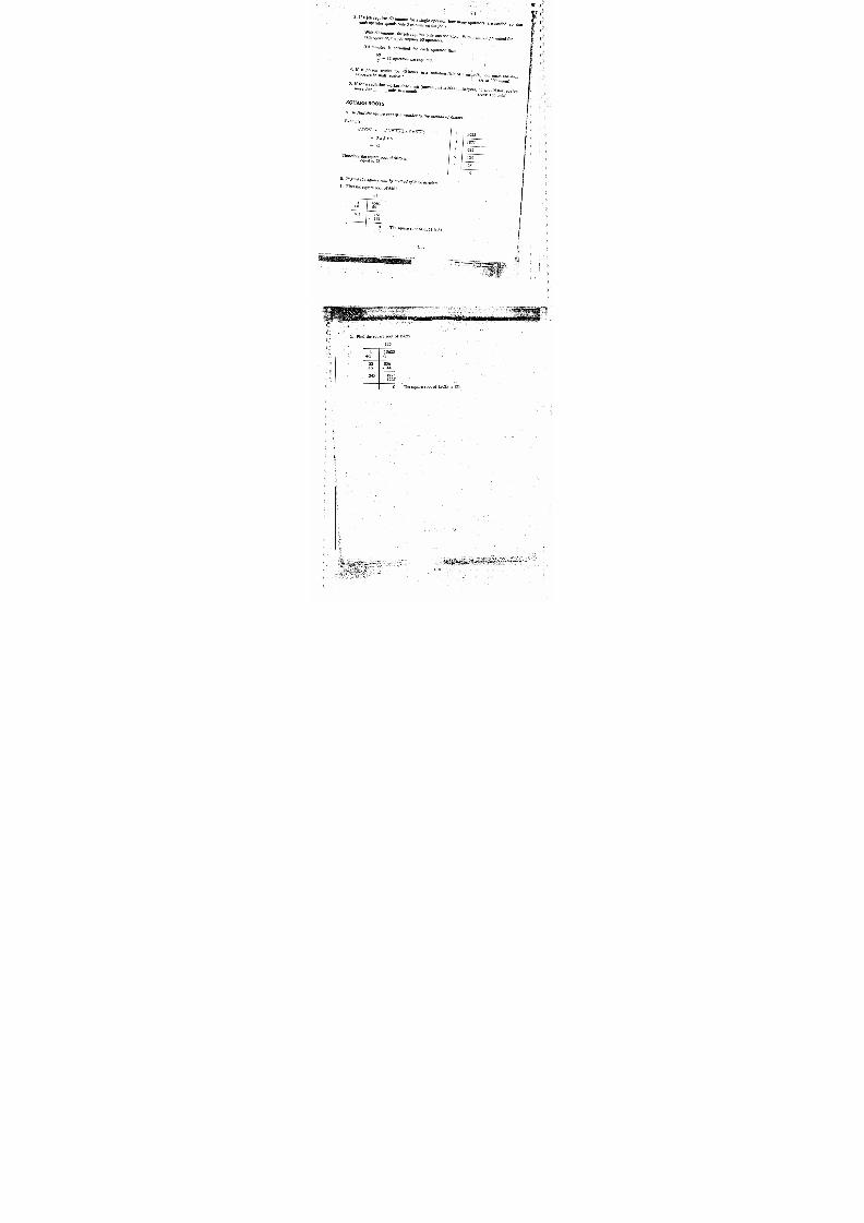
7/22/2019 BARC RT LEVEL II.PDF
http://slidepdf.com/reader/full/barc-rt-level-iipdf 92/160
I

7/22/2019 BARC RT LEVEL II.PDF
http://slidepdf.com/reader/full/barc-rt-level-iipdf 93/160
{
( .
4
3. examination of dense materials, like-.uranium alloys,
4. projective magnification .: Because of small focal spots, width of the order of I mm
in-betatrons , this techniq ue can be used for detecting small flaws.
In this technique , imag e of defect is projected bigger t han its natural size, by
keeping the film cassette at a distance behind the object. By this technique,sensitivity is improved , since the comparative size of defect image to film
unsharpness increases . In addition, proportion of scattered radiation reachinghefmreduces a•
5. Stroboradiography and Flash radiography : Since high energy X-rays f om linac andbetatrons are produced in series of short high intensity pulses, it is possible toinspect vibrating and rapidly moving systems and the techniques are calledstroboradiography an d flash radiography, respe ctively.
3: REAL TIME RADIOGRAPHY
This is an NDT method that produbes image of object, using penetrating radiation, which can be
viewed as the object is being.irradiated. This technique.was originally called Fluoroscopy.
The image can be viewed either directly or converted into video signal and seen on a TV
monitor. Principle of this technique is shown in figure 8.1.
X-rays
1. Test Specimen
2. Fluorescent Screen
3. Photo-cathode
4. Electron Paths
5. Viewing Screen
6. TV Camera Tube
7. Viewing Screen
a. Image Intensifier Tube with CCTV System
4 6
b. Solid State Intensifier
c. X-ray Vidicon
1. Test Specimen
2. Thin Metal Electrode
3. Photo-conductive Layer
4. Opaque Interphase
5. Electroluminescent Layer
6. Transparent Electrode
7. Support Plate
1. Test Specimen
2. Photo-conductor
3. Screen Grid
4. Viewing Screen
Fig. 8.1. Real Time Radiography
8 . 3

7/22/2019 BARC RT LEVEL II.PDF
http://slidepdf.com/reader/full/barc-rt-level-iipdf 94/160
3.1 : Advantages
1. Accept/Reject decisions can be made immediately without delay.
2. Object can be moved in the desired direction during inspection.
3. Automatic handling of systems is possible.
4: MICROFOCUS X-RAY RADIOGRAPHY
With conventional radiography equipment, when inspecting small diameter pipes, panoramic t
exposures are not possible , as U becomes more than the permitted limits. In addition, the
image magnification is not possibfe due to the same reasons.. Hence, small discontinuity in the
objects, may not be visible.
Microfocus X-ray units which have focal spots of the order of 10-100 microns are very useful for
examination of such objects. Principle of projection radiography, using microfocus X-ray units
is shown figure 8.2.
` ^ t- Focal
flit spot
/ 1t\
/ I t1\11\ \
Object -4
Flm I t \ \ Magnified image
of defect
Fig. 8.2 : Microfocus X-ray Radiography
8 . 4
C

7/22/2019 BARC RT LEVEL II.PDF
http://slidepdf.com/reader/full/barc-rt-level-iipdf 95/160
t
C ' 'TRAINING COURSE ON
INDUSTRIAL RADIOGRAPHY TESTING
AND SAFETY - (RT-1)
(VOLUME 2)
RADIOLOGICAL PHYSICS. AND.-ADVISORY DIV ISION
BIJAB 'HA ATOMIC RESEARCH CENTRE
MUM BAI 400 085
x'1997
Compiled b y
M.J. SUBRAMANYA AND S.P. AGARWAI,
Radiological Physics and Advisory Division, BARC

7/22/2019 BARC RT LEVEL II.PDF
http://slidepdf.com/reader/full/barc-rt-level-iipdf 96/160
1. Basic M athematics
2. Basic Radiation Physics
3. Interaction of Radiation with Matter
4. Radiation Quantities and Units
5. Biological Effects of Radiation
6. *Operational Limits
7. Radiation Detectors and Monitors
8. Radiation Hazard Control
9. Radiation Accidents in Industrial Radiography
10. Regulatory Aspects of Radiation Protection
11. Practi(al in Radiation Safety
1

7/22/2019 BARC RT LEVEL II.PDF
http://slidepdf.com/reader/full/barc-rt-level-iipdf 97/160
•1. BASIC 'MAT H EMAT1CS
CC
C
In industrial radiography , we need' to do certain calculations , say, for determining t he radiation
exposure to-6e given for getting a good radiograph; for finding cordoning off distance, etc.
These are simple calculations involving some .basic-mathematics..i.-0
POWERS
W e know that 1 kilogram (kg) mean s 10
1 kg = 1000. gm
It can also be w ritten as - 1 kg = 103 gm = 1000 gm
Also 1000 milligram = 1000 mg = 1 gm
Similarly, 1000 milli R/h = I R/h
103 mR/h = 1 R/h
By these; we understand
1 0 3 , =10x lOx 10 1000 ----______ (Kilo)
Similarly,
102 = lOx 10 = 100 ---- --------- -
106 = 1O x to x 10'x 10 x 10 x 10 = 1,000,000 (Mega)
109 = lox lox lox lox lox lox 10x lox 10( Olga)
103 is called 10 cube or 10 raised to power. 3.
2.42 is called 4 square or 4 raised to power
102 is called square of ten or ten square
104 i s called inverse -square of ten
11_1
that is 10-2= 102 , 10 x 10 loo
MULTIPLICATION & DIVISION
If y = 0.5
20y=20x0:5= 10
If 6x=210
x = 210 = 35

7/22/2019 BARC RT LEVEL II.PDF
http://slidepdf.com/reader/full/barc-rt-level-iipdf 98/160
A. If one mang o costs Rs . 2/- what i s the cost of six mangoes?
Cost of one mango = Rs. 2/-C ost of- six mang oes 2 x 6 Rs. 12/-
Similarly, we can work out t he following
If radiation level at a place with one curie source is 12 mR/h, what would be the level at thesame place with 8,Ci source?
The answer would be 12 x 8 = 96 mR/h.
B. If one dozen oranges cost Rs. 24 /- what is the cost of one orange?
12 oranges cost Rs. 24/-
one orange costs Rs. 24 = Rs. 2/-
what is the activity of the source if onI Um-,Y,1 source mR/h,
e i i
4
In a similar way, if the exposure rate at 1 meter from an I 'd'
cur e ridium -192 gives 500 mR/h at1 meter ?
Given : Exposure rate at 1 meter = 2000 mR/h from the source
Known : Exposure rate at 1 meter due to 1 Ci iridiumr-192 = 500 mR/h
Activity of the source= 2000
500= 4 Ci
DECIMAL REPRESENTATION
a. Quarter kilogram can also be called 1 /4 kg or 0.25 kg or 250 gram.
0.25 kg = 0.25 x 1000 gram = 250 gram (1 kg = 1000'gram)
b. If the distance between A and B is 254 cm, what is the distance in meters ?254
100 = 2.54 meters [Since 1 meter = 100 cm]
C. 0.057 = 571000
d. 0.5 R/h = 0.5 x l0fi0- mR/h = 500 mR/h
e. 2500 mR = 25001000 R = 2.5 R
1.2
I

7/22/2019 BARC RT LEVEL II.PDF
http://slidepdf.com/reader/full/barc-rt-level-iipdf 99/160
h. 15cm= m=0.15m1 V V
w hat is t he'speed per minute and per hour ?
In 1 minute he will travel 2500 = 25030 _ 3 meters/min
TYPICAL PROBLEMS
la. If a man travels 2500 meters in 30 minutes
.
In 30 minutes tie travels 2500 meters
In 60 minutes (1 hour) he will travel 23 x 60 = 5000 meters/hour
= 5 kilometers/hour
lb., If a man standing at a place for 15 minutes receives 50 mR exposure, what is the expo-.sure rate per hour or radiation level at that place ?
_ Exposure in 15 minutes = 50 mR
Exposure in I :minute = IS mR
Exposure rate or radiation level = s x 60 mR/h =-200 mR/h
2a. If a man drinks 0.5 litres milk per day. How much milk will drink in 2 months ?
In 60 days he will drink = 0.5 x 60
1 month = 30 days
2 months = 30 x 2 = 60 days
in 1 dayhedrinks 0.5 litres milk
51 0x 60 30 litres milk.
Exposure rate with I Ci iridium-192 = 20 mR/h
Exposure rate with *15 Ci iridium-192 = 20 x 15 mR/h =.300 mR/h
2b. If theradiation level at a particular distance from a nne c^ w r?e.ir idium
- 192 source is0 mR/h, what is the radiation level at the same distance . from . a'curie. iridium-192ource?

7/22/2019 BARC RT LEVEL II.PDF
http://slidepdf.com/reader/full/barc-rt-level-iipdf 100/160
3. If a job requires 60 minu tes for a single operator, how man y operators Fareeach operator spends only 5 minutes on the job ? needed so
With 60 minutes, the job requires only one operator. With 1 minute permitted foroperator, the job requires 60 operators. or
If 5 minutes is permitted for each operator, than
60
= 12 operators are required.
4. If a person works for 40 hours in a radiation field of 5exposure he shall receive ? mrejm/h, how much radiation
(A '1s: 200 mrem)
5. If for a radiation worker dose limit (maximum) is 2000 units/year, he shouldmore thanunts ina monh no receive
(Ans: 166 units)
SQUARE ROOTS
A. To find the square root of a number by the methodof factors.
Example:
5 25 :3x5x5x5x5
= 3x5x5
= 75
Therefore the squareroot of 5625 isequal to 75
B. To find tie square root by method of long division
1. Find the, square root of 6561
8 1
8 I 6 5 6 1+8 - 64
1 6 1 ' 161
^- 161
I 0. The square root of 6561 is 81.
1.4
5
3 5625
3 1875
5. 625
5 125
5 1 25

7/22/2019 BARC RT LEVEL II.PDF
http://slidepdf.com/reader/full/barc-rt-level-iipdf 101/160
1 2 5
L -
+ 1
22+2
24 5
1 5 6 2 5- 1
056- 44
1225- 1225
0 Thequare root of 15625 is 125.

7/22/2019 BARC RT LEVEL II.PDF
http://slidepdf.com/reader/full/barc-rt-level-iipdf 102/160
iridium , gold, lead are - some of the elements we are familiar with.All materials in the universe are made of different elements . Hydrogen , oxygen, iron,
Atomis the smallest part of an element. An atom has a positively charged central portion
called 'nucleus '. It also has negatively chargedelectrons going around the nucleus, in
different orbits . The nucleus has two types of particles - protons which are positively charged
and neutronswhich do not carry any charg An atom, is electrically neutral as the number
of protons in its nucleus is equal to the number of^electrons in the orbits. structures of someic
atoms are shown in figure 2 . 1. The r &L-Q- 2 Ln-n atom is kncLiacn . as its g t v m *
numberMEvery atom of a particulars element has a definite number of protons eg.,
aluminum has 13, cobalt has 27, iridium has 77 protons.
Hydrogen (lp) Helium (2p+2n) Carbon (Gp+6t:)
Fig. 2.1 : Atoms of Some Elements.
The mass of an atom is almost completely concentrated in the nucleus, as electrons have
negligible mass. A proton or a neutron is about 1800 times heavier than an electron. Mass
number (A) of an atom is the number of protons (Z) plus the nunber of neutrons--M) in its
-nucleus, ie., A = N + Z. Atom of any element X is reresented as
AX
Z
2. BASIC RADIATION PHYSICS
A - Mass number
Z - Atomic number
1 H1
Hydrogen
Fig. 2.2 : isotopes of Hydrogen.
2.1
3H
Tritium

7/22/2019 BARC RT LEVEL II.PDF
http://slidepdf.com/reader/full/barc-rt-level-iipdf 103/160
( 'The chemical behavi oLan element . is de endent urel on the atomic - number,. Any. atom or
.^ _nuclide haven me number bfprotons W
. but haven different number of neutrons (N) is
hown in figure 2.2.called an isotope of the element . Isotopes of hydrogen are s
191Ir, 192Ir and 193Ir are isotopes of iridium . Similarly,77a77 77
t. _
Some isotopes are stable others are unstable Th e stabili ty of an isoto p e , depends upon the
relative number of neutrons and Drotons in its nucleus A:'. unstable nucleus becomes stable
by fitting radia ionssuch as alpha paricle beta arti Thisprocess is known as
radivactTheref re, unstable isotopes are known as radioactive isotopes (or
radioisotopes In the above examples,
27 Co, .27 Co and 27o are isotopes of coba
3
1H' 1 ' 77
92. 1 'r,
58
2 7 C o
eRadioactivity is a spontaneous process. It is not affected by-external influences
the element etstemperature, pressure; .dilution, etc. On emission of alpha or beta particles
converted intnew element. 'Thus, a radioisotope is saidto transform (disintegrate
or decay)into a new element along with the emission cf one or two types of particulate
. Quite often, this is followed by the emission of electrQmaanetic radiationradaoncaedgamma radiation. Emission of. different types of radiation are shown in figure 2.3. A
ll
radioisotopes mentioned above, except 3H, emit gamma radiation.
Alpha particle
(a protons &P. neutrons
Fig-.:23 :;'Emission of D ifferent Types of Radiation.
nerall among Heavier elements . They are called naturaUX, g ,adioactivity exists in natuce e
occurring radioisotopes . . Potassium-40, carbon - 14, uranium -238 are some of. the naturally
Many other elements can be made radioac^t' ve by bombarding themoccurring radioisotopes .

7/22/2019 BARC RT LEVEL II.PDF
http://slidepdf.com/reader/full/barc-rt-level-iipdf 104/160
w ith ch arged particles and neutrons . These are called artificially made radioisotopes.Cobalt -60, iridium - 192; caesium -137 are some of the a rtificially made radioisotopes.
llItIlillll! IlllilThllllilllili1 l i I I I I I I I l l I I 1 i J I I I I I I I j j jIilll'I !33I II tli IiiljfliIillJl flhf I i l l i+ E I ! I ^ I l l
I .t I^ 1
l ^(( l!I r ^ !
^ ^ ^ I I I I ^ j l
I n i t i a l l g r- Af ter
1 Halflife 2 Httlflives 3 Halflives
Number of
radioactive i
atoms
N
1
Activity (Bq) ,48
Sou rce s ize r Nochange
Nochange
Nochange
Radiation 1 No No Noenergg change change change
Fig. 2.4 : Reduction in Radioactivity with Time.
Rate of transformation
(transformation / second or disintegration / second) gives the amountof radioactivity or strength of the source. Activity is expressed in units of
Becquerel (Bq) orCurie (CY).
A source, of activity 1 Becquerel willundergo I transformation / second.PeaseChe
A source of activit y 1 Curie will undergo3.7 x 10i0 transforations ; second
2.3.
e apter 4 on
Radiation Quantities and Units.

7/22/2019 BARC RT LEVEL II.PDF
http://slidepdf.com/reader/full/barc-rt-level-iipdf 105/160
TIONSF RADI ;ENERGY
All radiat ions have energy . Energies of'various radiations (a, B, r) are usually specifie d in
electr on v olts.
One electron volt is theenergy given o a sijigle election as-it moves across a potential
difference. of one volt.
1 eV = 1 electron volt. = 1. 6 'x 10'12 erg
1 keV 1 kilo electron volt = 1. 6 x 10'9 erg
I MeV = 1 million electron volt = 1.6 x 1V erg
Data regarding t he most commonly used radioisotopes in industrial radiography is given in the
'Fable 2.1.
ABLE 2.1 : RADIOISOTOPES COMMONLY USEDIN INDUSTRIAL RADIOGRAPHY
Radioisotope Half life Main Gamma Energy(MeV) .-
Cobalt-60 5.3 years I .17 & 1.33
Iridium-192 74.5 days 0.24-0.67(0.4 KeV Average)
PRODUCTION OF X RAYS
X and gamma radiations are similar in nature, biological effects and' action on photographicare
film. Gamma rays are emitted by the nucleus of a radioisotob whereas, X-rays are
produced outside the nucl hen high energy electrons interact with'atoms (target). a
these electrons interact with the field near The nucleus: they are stopped •or def! d with lesser
energy. * The energy difference between, the incident electron and the deflected electron is
given out in the form off:X-rays.. The energy of X-rays depends upon the closeness of theaced wi continuous energ ,ithoddi
electron path to. the, target_nuc)yA. H
enncce.. .X-rays are pr
. .a maximum
equal to the energy' of the .inc^ ent electrons X-ray production increases with
increase in atomic numbet of the target atom.. It also increases with increase'in the incident
electron energy.
In an X-ray machine, the•electrons, emitted by the heated filament '4re_made to strike a
tungstentarget placed, at higher voltage with respect to the filament. As a result of
interaction between the electrons and target. atoms , X-rays are produced.
For more details on X-rays, refer to chapter on X-ray Techn ology.

7/22/2019 BARC RT LEVEL II.PDF
http://slidepdf.com/reader/full/barc-rt-level-iipdf 106/160
SUMMARY
I. ATOM is the smallest part of any elemen t.
2. Atom consists of NUCLEUS at the centre and ELECTRONS around the nucleus.
3. The nucleus consists of PROTONS and NEUTRONS.
4. Any atom of an element has a definite number of protons in its nucleus. _
5. The number of protons in the nucleus of an atom is called itsATOMIC NUMBER (Z).
6. The number of protons plus the number of neutronsin the nucleus of an atom is called itsMASS NUMBER (A).
7. ISOTOPES are atomswith same atomic number, but different mass number
8. Alpha or beta radiations are emitted when an atom is UNSTABLE.
9. The isotopes which emit radiations are called RADIOISOTOPES.
10. A different elemet•it is formed after the emission of a radiation.
11. Some isotopes emit gamma radiatiens;..after the emission of alpha.or beta radiations.
12. All radiations have energy.
13. ALPHA RADIATION has two protons and two neutrons and is positively charged and isleast penetrating.
14. BETA RADIATION is an electron with negatively charge.It is more penetrating t hanalpha radiation.
15. GAMMA RADIATION has no charge or mass. Hence, it is highly penetrating.
16. HALF LIFE of radiation source is the period in which its activity reduces to half of itsinitial activity.
17. X -rays are similar to gamma rays, except their origin and m ethod of production.
18. All the above radiations can ionize and excite matter and hence, are called IONIZINGRADIATIONS.
19. IONIZING RADIATIONS cause bioiogicai damage.
20. It is necessary to protect ourselves from such hazards.
2 . 7
I

7/22/2019 BARC RT LEVEL II.PDF
http://slidepdf.com/reader/full/barc-rt-level-iipdf 107/160
Cr
!.
.j
3. INTERACTIQN OF RADIATION WITH MATTER
When X, t3, z radiat ions fall on a material , interactions take place between the radiation and
the electrons' in the mat erial . This leads to absorpt ion and scat ter ing (moving i n a different
direction) of radiation . A part of the incident radiation may also get t ransmi t ted (pass
through).
The amount of-radiation .transmitted t hrough the mat erial depends upon.
a. type of radiation (X, 8, r)
b. energy of radiation (eV, keV, MeV)
c. type of material and i ts th ickness (air, iron, lead)
Beta radiations can be completely absorbed in any medium. Fo' ex m
ple, betas of
d iation
alums with
Emax (maximum energy) 1.7MeVcan be absorbed completely
But in .the case of X and gamma radiations complete absorption is not possible: For example,
one per cent of cobalt-60 gamma radiations still get transmitted through 8 centimeters of lead.
There are three main types- of interactions for Xand gamma radiations in any medium: These
a r e
a. photoelectric effect
b. Compton effect
c. pair production
But, for energies we normally come across in industrial radiography, only the first. two
interactions are imp ortant.
The photoelectric effectis an interaction between a gamma ray (photon)
and an orbital
electron .The gamma radiation looses its complete energy to the electron and the electron is
removed from its orbit. This electron is called pho ol1n`eraction , ise^redominagt.i?th_
particle easily gets absorbed in the medium. This4---Pt with i
ncrease, in ato llm
energies and it decreases wu ^^ ^^^^^. a ^ .•• .o, ._
of the object. Hence, higher atomic number materials, like ea ,uranium , tungsten, etc.
absorb gamma radiations better than lower atomic number materials,. likeplastic,aluminum,
iron, etc.
In Compton effect, gamma radiation interacts with a free eecttrOIn. iThe(ee am maeradiation
.gives part of its energy to'the electron and travels in a different
decreased energy. The electron moves in another direction. This effectis predominant at
number of the material,r a 1 it is nnr t4-nPnrlPnt on the atomic
'These tw o interactions are shown in I igurc.3. I .
Whenan electron is removed from it s orbit, the at om looses
. oct -negative charge . In other
asthis process is knownce ,nwords, the atom gets positively charged or ionized . •
4 2 0

7/22/2019 BARC RT LEVEL II.PDF
http://slidepdf.com/reader/full/barc-rt-level-iipdf 108/160
ionization . When an electron is raised from an inner orbit -,o an outs orbit. the elc:cron getsextra energy . In other words , the atom gets exciu.d. Hence, this process is •; alled excitation.
Alpha, beta and gamma radiations can directly or indirectly cruse ionization and excitation inmaterial with which they interact. Hence, these radiations are called ionizing radiations.
Phot nelectric effect Compton scattering
photoelectron a compton electron •
scatteredphoton
Fig. 3.1 : Photoelectric and Compton Interaction.
The intensity of radiation reduces on passing through any material. In case ofradiations ., the attenuation follows an exponential law :
I = I e^'0
where, I0 is the intensity of the incident radiation beam, I is the'intensity of the `^
after passing ti^rough a thickness x of the materiel and p is known as linecoer'ficient. It is defined as the'fractional decrease in intensity per unit the:'
material. If the energy region of 100 keV to 1.5 MeV is considered, the attenuate
decreases with increase in energy and it increases with increase in atomic
absorber material. Hence, lower energy radiations are better absorbed and
number material are good absorbers.
Half Value Thickness (HVT)
The thickness of the material, usually called absorber, (eg., steel , lead, depleted
needed to reduce the intensity of radiation to half its initial value is known as tthickness .(HVT).
The HVT depends on the energy of radiation and the nature of the absorber.
In the case of X-rays, the HVT value for any kV depends to some extent on
inherent filtration of the X-ray tube. However,'the value of HVT for a given r.
taken as constant for heavily filtered beam.
As higher atomic number materials provide better shielding than lower at_
3.2
i
gamma

7/22/2019 BARC RT LEVEL II.PDF
http://slidepdf.com/reader/full/barc-rt-level-iipdf 109/160
material,-for a given energy, HVT value is lesser fo: higher atomic number mat erial.
C
One BVT of any material_reduces the intensity to half of the original ' intensity. Two HVT
reduces the intensity to 16 x,'h.. _ (1h)2; ie., 1/4 .of.the original intensity. In general , 'n'. HVT
reduces. the intensity to ('h)°. (Recall the decrease of.radioactivity4-with time)"
The reduction in radiation intensity with abs rbers c'f d ifferent half value thickness is shown in
f i g u r e 3 . 2 .
A
Radiationtntenaltg
1 / 2
1/ 4
I/ 8
Source
. . . . . . . . . . . . . . . . . . . . . . . . . .. . . . .
t No. of Half Value Lagers ->
MN1\N}NN\}\\}NNNN INW'
Detectorx
No. of HVT 0 12 3
Radiation I I2
I4
I
aintenaitg
100 GBq Ir-192
at 1m11.4 rGU 5.7 mGg 2.85 mGg
Fig. 3.2 Reduction in Radiation Intensity with Thickness.
1.43 mGg .

7/22/2019 BARC RT LEVEL II.PDF
http://slidepdf.com/reader/full/barc-rt-level-iipdf 110/160
TA B L E 3.1 : HVT AND T V T VALUES F O RX AND.GAMMA RADIATIONS
Material
Concrete Steel Lead Uranium
HVT TVT HVT TVT HVT TVT HVT TVT
Radioisotope cm cm cm cm cm cm cm cm
Iridium -192 4.6 1 4 1.25 4.0 0. 48 1.6 .0.31 1.0
Coba l t -60 6.6 21.8 2 .0 6.6 1.2 4.0 0.7 2.2
X-rays
HVT TVT HVT TVT HVT TVT
mm. mm mm mm mm mm
100 kV 1 6 5 5 1 . 2 3 . 8 0 . 2 5 0 . 8 4
150 kV 22 70 2.3 7 .6 0. 29 0.96
200 kV 26 86 3 . 8 1 2 . 7 0 . 4 2 1 . 4
250 kV 2 8 9 0 5 . 4 1 7 . 7 0 . 8 6 2 . 9
300 kV 30 100 6.5 21.5 1.7 5.7
Tenth Value Thickness (TVT)
Tenth value thickness is the thickness of any material needed to reduce the radiation intensity
to one tenth of its initial value . Similarly, Two TVT reduces the intensity to 1/10 x 1/10 =
(1/10)2 ie ., 1/100 of the original intensity. Generally, 3.3 TVT reduces the intensity by a
factor of 10, hence
1TVT=3.3HVT
HVT and TVT values in different materials, for X and gamma rai iat ions , are given Table 3.1.
Example 3.1
The radiation level at a place, due to an iridium-192 source is 10 mR/h. What is the thickness
of steel required to reduce the level to 2.5 mR/h?
Radiat ion level at the place = 10 mR/h.
One HVT reduces the level to 10 =2 =5 mR/h.
One more HVT reduces the level to 5 -. 2=2.5 mR/h
Two HVT of steel for iridium -192 = 2 x 1.25 cm = 2.5 cm.
3.4
yLp Lx.' h 'fN Q{ ' ,. •ryY'L5.:4 I <'^Y}`Tr'y `I ` . y °}'H
7/22/2019 BARC RT LEVEL II.PDF
http://slidepdf.com/reader/full/barc-rt-level-iipdf 111/160
9. Alpha ,beta and gamma radiations can cause ionization or excitation
. Hence. these'adiations are calledIONIZING RADIATIONS
10. Higher atom ic number material , like lead, uranium , absorb X and gamma radiations betterhan lower atomic number material , l ike plastic , aluminum.
11. HALF VALUE THICKNESS (HVi) of anymaterial reduces the radiat ion intensi ty at alace to half of the original intensity.
12. TENTH VALUE THICKNESS (TVT) ofany material reduces the radiat ion intensi ty at aplace to one tenth of the original intensity.
3.6

7/22/2019 BARC RT LEVEL II.PDF
http://slidepdf.com/reader/full/barc-rt-level-iipdf 112/160
Ex-ample 3.2
What isthe thickness of lead required to reduce the radiation intensity at a place, due to
cobalt-60 source from 1000 mR/h 5
Radiat ion level at th e place
= 1000 mR/h.One TVT reduces the level ,to 1000 _ 10 = 100 mR/h'.One more TVT reduces the level to 100 _ 10 = 10 mR/h.One HVT added to this reduces thelevel to
10 -: 2 = 5 mR/h.
Two TVT and one HVT of lead for cobalt -60 radiations= 2 x 4 + I x 1 . 2 cm = 9.2 cm.
Examale 3.3
The radiation intensity at a place from a 200 kV X-ray beam is 5000 mR/h. This has to be
reduced to 2.5 mR/h. What is the thickness of concrete required to achieve this?
Radiation intensity at the place= 5000 mR/h.
3 TVT reduces this level to 50)0 _ (10.x 10.x 1U) -. 5 nmR/h.
One HVT added to this reduces the level to 5 _ 2 = 2.5 mR/h.
3 TVT and one HVT of concrete for 200 kV X-ray beam
=3x86+ I x26= 284 mm =28.4 cm.
SUMMARY
1. Beta radiations can be absorbed completely. But X and gamma radiations cannot beabsorbed completely.
2. Interactions of X and gamma radiations, in any material, are similar.
3. X and gamma radiations undergo three types of interactions in any material: Photoelectriceffect, Compton effect and Pair production.
4. For energies of interest in industrial radiography, only photoelectric effect and Comptoninteractions are important.
5. PHOTOELECTRIC EFFECT is important at low energies. It decreases as energy ofradiation increases. It increases as atomic number of the absorbing material increases.
6. COMPTON EFFECT is important at medium energies. It decreases with energy. Itdoes not vary with the atomic number of the absorbing material.
7. IONIZATION is a process, in which electrons are knocked off (removed) from an atom.
8. EXCITATION is a process, in which electrons are raised from an inner orbit to an outerorbit.
C3 . 5

7/22/2019 BARC RT LEVEL II.PDF
http://slidepdf.com/reader/full/barc-rt-level-iipdf 113/160
4. RADIATION.QUANTTFLES & UNITS
Units are necessary. for quantitative description of any physical processor phenomena.
radiological physics, un its are required to measure
a. Radioactivity,
b. Exposure,
c. Dose,
d. Equivalent Dose.
Radioact iv i ty of a source is measured in terms of the number of transformations i t undergoes
in one second.
RADIOACTIVITY
The unit of radioactivity is Becquerel.(Bq)
One Becquerel corresponds to one transformation per second. Formerly, the unit of activity
was Curie (Ci) corresponding to 3.7 X 10¹⁰ transformations per second.
1 Ci = 3.7 x 10¹⁰ transformations/sec
3.7 x 101°Bq = 37 x 109 Bq := 37 GBq
Subm ultiples of Curie viz., 1 mCi'(1/1000C i) and 1 ACi (1/106C i)are occasionally used.
EXPOSURE
In order to obtain information about quantity of X or gamma radiation present at a point of
interest, the concept of exposure is used, which is based on the ability of radiation to produce
ionization in air.
The unit of exposure is Coulomb per kg (C/kg;, which is defined as the quantity of charge
produced by ionizing radiation. in 1 kg of air.
The earlier unit of exposure was Roentgen' (R) which was used for X or gamma rays upto
3 MeV. This wAs defined as the amount of exposure due to X or gamma radiation o energy.
upto 3 MeV which would cause ionization resulting in 1 electrostatic unit of charge of either
sign in I cc of air at STP (Standard Temperature and Pressure).
1 R = 2.58 X 10⁻⁴ Coulomb/kg (C/kg).
k
DOSE.
The dose from ionizing . radiation is the energy imparted , to matter by the ionizing r:.: iation,
per uni t mass of the irradiated. material at the place of interest.

7/22/2019 BARC RT LEVEL II.PDF
http://slidepdf.com/reader/full/barc-rt-level-iipdf 114/160
I I
I
The unit of dose isJoules per kilogram (!/kg)
The specialname for the unit,of dose is
Gray (Gy)
I Joule = .107 erg
Therefore,
If one jouteis
I Grade of energy isimparted by any radiation
in one kilogramof any material, the dose
The concept of dose applies to An•ys a measure of energy
a medium, all types of radiations and all energie;. The doseeposited by radiation in the irradiated material.radiation - physical, chemical and biological depend upon the dose.
All effects of
Formerly, the unit of dose was rad.material. One rad corresponds to 100 ergs/g of irradiated
Hence,
1 Gray = 1 Joule/kg= 10 erg/kg
= 104 erg/g = 102 rad
1 Gy = 100 rad or I rad = 0.01 Gy.
Dose rate in terms of Gy/h, Gy/year, rad/h or -rad/year, e
etc., are also occaslona!!y used.In the case of exposure, for
practical convenience, used to specifythe radiation quantity instead exposure. the concept of air kerma is
Kerma
is the total kinetic energy of all the charged particles releasedthe ionizing radiation.
in 1 kg of the medium by
Air kermagives an idea about the energy transferred to air.
The unit of air kerma isJoules per kilogram (Gy).
I air kerma Gy = 114 R.
The usefulness of air kerma can be extended to the determinatr,
'on of the radiation output at apecified distance from a radiation source in terms of mG
y per hour.EQUIVALENT DOSE .
The biological damage suffered by the tissue exposed to different radiations mayThat is, the biological damage due to I G y1 Gy of gamma dose. y of alpha dose would be different y be different.
ue
types of radiation is different This is because the energy loss per unit path lan, -
greater ionization particles, because of their larger charge and mass, cause
per unit path length than gamma radiations, which mediate through singly
4.2
I

7/22/2019 BARC RT LEVEL II.PDF
http://slidepdf.com/reader/full/barc-rt-level-iipdf 115/160
C
c
charged electrons , _..Hence, one:G y of .alpha dose is approximately 20. times more effective in
causing biological : damage, compared to one G y of gamma or X-ray dose . To account for
this variation among different types of radiations, a term known as the R adiation W eighting
Factor (WJ is used to modify the doses due to each type. of radiation. Thu s, Equivalent Dose
is obtained by multiplying 'd9se' by the radiation weighting factor corresponding to theradiation of interest.
t
r
The unit of equivalent dose is also Joules per kilogram
The special name for the unit of equivalent dose is Sievert (Sv).
Equivalent Dose in Sv = Dose in Gy X W.
Formerly, the equivalent dose was called Dose Equivalent and its unit of was rent and WR
was called Quality Factor (QF).
1 Sv = 100 rem or 1 rem = 0.01 Sv.
Equivalent D ose is a measure of biological damage caused by radiation.
Radiation weighting factor for X-rays being on, equivalent dose in Sv can be considered as
.quivalent to dose in Gy. Therefore,- for Xand gamma rays,--
1GySv
1 rem = 1 rad
c
c .
c
KILOVOLTAGE (kV)
The potential difference applied between the cathode and the anode-of an X-ray machine is
expressed in terms of kilovoltage ( kV). It determines the maximum energy of X-rays
produced by the equipment . For example, when the potential difference applied is 300 kV,
energy of X-rays produced varies from 0 to 300 ke7. Higher the -applied potential
difference , higher is the energy of the X-rays emitted and : higher is the penetration. In an
X-ray equipmer . t, the energy of X-rays can be varied , depending upon the thickness of the
. object to b e radiographed , by altering the applied potential difference.
MILLIAMPERE (mA)
Milliampere (mil.) of an X-ray unit indicates thecurrent flowing through the it-lament circuit.
The intensity of X-rays at a given applied voltage is proportional to the current flowing
through the filament. The •intensity of X-rays at 10- mA is twice the intensity at 5 mA. The
exposure to be given for a radiograph , at a given potential is indicated in terms of mAs, ie.,
the product of filament current and duration of exposure (sec). The exposure due ,C ^ A
current for 2 minutes is equal to that due to 5 mA current for 4 minutes ( 1200 mAs). The
total use of X-ray equipment or work load is expressed as mA -minutes or mA-seconds.

7/22/2019 BARC RT LEVEL II.PDF
http://slidepdf.com/reader/full/barc-rt-level-iipdf 116/160

7/22/2019 BARC RT LEVEL II.PDF
http://slidepdf.com/reader/full/barc-rt-level-iipdf 117/160
C
l
I 5. BIOLOGICAL EFFECTS OF RADIATION
CELL
Cells are the basic units of living organisms . All tissues are made of cells. Adult human
body consists of about 1014 cells. Cells of different organs carry out the functions specific for
those organs . For example , nerve cells are responsible for transmitting electrical impulses
from one part of the body to the other ; liver cells are responsible for metabolizing the food 'we
tak e and preparing nutriti on for all other tissues in the body; red blood cells carry oxygen and
nutrition to all tissues.
Cells of different tissues have different siies and shapes. However, in general , they all contain
a central nucleus' (with the exdeption : of red blood cell), surrounded by a viscous-fluid called
cytoplasm . The nucleus contains chromosomes which constitute an array of genes. The
chromosomes control all the functions of the cell and hence , of the tissue. The cytoplasm
contains various membrane systems and other components that are necessary for the function
of the cell.
Cell Division
Cells originate or mul t ip l y from preexisting cells by the process of cell division . For example,
a human being, like any other animal, develops from a single cell, which is formed by the
fusion of . two gcrm-ceiis, one from - the father and the other from the mother . Duringte nine
month period o :' pregnancy , this cell undergoes a number of divisions. The new cells in turn
specialize to form various organs of the fetus (unborn baby). After birth, cell division
cont inues unt i l ^ he organs attain adult proportions . Cells in many tissues of the body have life
span shorter than that of the body, as a whole . , For example , intestinal cells , blood cells,:skin
cells, etc., have life span ranging from a few days to a few weeks. They wear out and die.
They are continuously replaced for the proper function of the tissue. Hence, even in an
adult , cell division continues in some tissues. Tissues undergoing cell division are. more -
sensitive to radiation than others.
From the point of view of radiation hazard , cells. can be classified into tw o groups : a) Somatic
Cells, b) Germ Cells . Germ cells are the ones involved in reproductive process . T1iey are
sperms in the male and eggs in the female . All other cells in the body are somatic cells.
BIOLOGICAL EFFECTS OF RADIATION
When radiation passes through the body, it transfers some of its energy to the cells in the form
of ionizations and excitations , which in turn lead to a number of chemical changes.
Generally, these chemical changes are harmful to the cells. Depending upon the seriousness
of the harm, a cidier dies or gets modified . All the biological effects of radiation arise
from these two effects on cells - Cell Death or Cell Modification.
Radiation can cause breaks in chromosomes . Majority of these breaks get rep^.ired, but
certain breaks may lead to loss-or rearrangement of genetic material which can,,be se::. under a

7/22/2019 BARC RT LEVEL II.PDF
http://slidepdf.com/reader/full/barc-rt-level-iipdf 118/160
microscope . Such events are calledChromosome Aberra t ions .
Biological effects of radiation can be classified into two groups, depending upon the typeells damaged. They are somatic effects and heredita effects. As the name itself suggests,
somatic effects arise from damage to somatic cells and they occur in the tissues of the exposedperson (eg., effects on skin , blood ,
lung, bone, thyroid, etc.). Hereditary effects arise from
damage caused to the germ cells and occur in the progeny of the irradiated person.
Somatic effects can l e furth, : r divided into early and late effects.
Early Somatic Effects
Whenever the body is expc .ed to radiation : some cells are killedlow doses, since only a few cells are killed, the body can cope: up and some are: . At
with the los s and
mod i fied
hence nommediate effects are. seen . However, as dose increases , more and mote cells get killed andhis results in radiation sickness ,nausea (feeling like vomiting), vorniting, fatigue, etc., withina few hours of irradiation . However.
-these effects are transient and disappear after a fewours . As dose increasesfurther, the effects appear quicker,
are more severe and last longer.t sufficientlyhigh doses, the damage caused to important organs such as I lood formingorgans, intestine , etc., is so severe ,
the patient will not be able to recover. Ant:mia, infectionand high fever would occur , leading to death . Fifty per cent of the persons exi osed to a dosen the range3 - 5 Gy, die within a period of 60 days. This is
known as LD_ At stilli.;her doses, deathoccurs earlier. 060
Instead of the whole body, if only a part of the body is exposed, the damage is confined to the
.exposed part. Depending upon the part of the body exposed, different local effects at different
doses are produced. Skin is the most frequently exposed organ. Doses less than 5 Gy can
cause only a transient (temporary) erythema which lasts for 1-2 days. Higher doses of the
order of 10 Gy can cause reddening of the skin, fixed erythema and very high doses cause dry
or wet desquamation depending upon the severity of loss of epidermal basal cells, within 3-6weeks (10-25 Gy). Doses higher than
25 Gylead to late phase of erythema during 8-16 weeks,
finally leading to death of the tissue. If hairy parts are exposed, in addition to erythema, hair
falls off, leading to epilation. Another sensitive organ is the reproductive organ - testes in
male and ovaries in female. Due to death of the germ cells sterilization results. This may be
temporary or permanent depending upon the dose. When eyes are exposed, the cells in the
lens are killed leading to the opacity of the lens, which is called cataract. Unlike her effects
which appear within a few days -or weeks after exposure, cataract formation takes a meanlatent period of 2 to 3 years.
In brief, radiation exposure may lead to various types of early somatic effects depe;;,jing upon
whether whole or only part of the body is exposed. The characteristic of the eariv somaticeffects are:
a. they do not occur below a certain dose (threshold dose),
b. severity of the effect increases with dose and
5.2

7/22/2019 BARC RT LEVEL II.PDF
http://slidepdf.com/reader/full/barc-rt-level-iipdf 119/160
I
1' c. they appear wit hin a short tim e after exposure (except cataract).
Table 5 .1 shows some of the early somatic effects and their threshold doses . It is generally
assumed that the exposure takes place within a short time - minutes to hours(acute exposure)
If the doses are .protracted (chronic exposure),then the threshold doses will be -much higher,' .since the effectiveness - of radiation decreases due to the recovery process.
TABL 5.1' SIGNIFICANCE OF DIFFERENT LEVELS OFRADIATION EXPOSUR E
Dog(-
1-2 mSv/y 100-200 mrem/y Whole body
1 mSv/y 1(0 mrem/y W hole body
5 mSv/y 500 mrem/y Whole body
10 mGy . ' 1 rad Whole body
20 mSv/y 2 rem ./ y Wh o le body
150 mSv/y 15.rem/y Eye
500 mSv/y 50'rem/y.. . Partial body
100' mG y I0 rad ' W hole body
1 Gy 100 rad Whole body .
1 •G y , 100 rad Reproductivesystem
2.3 Gy 200-300 rad W hole body
3-5 Gy '300-500 rad W hole body
> 6 Gy . > 600 rad. Partial body
Significance
Backg round radiation level at sea level(outdoors)
Limit for non-radiation workers.
Average occupational exposure..
Risk'of cancer mortality,about 5 per 10000 exposed
Limit for radiation workers.
Limit for-t ,ye lens.
Limit for skin and extremit ies.
Detectable increase inchromosome aberrations.,
No detectable injury or sickness.
Threshold for radiation sickness[Nausea, Vomiting, Diarrhea (NVD)j(5-10 %.of exposed individuals).
Temporary steri li ty in men.
Threshold for epilation'Threshold for induction of cataract.Radiation sickness in most individuals.Early erythema induction.
LD 50/60 for human beings.
Threshold dose of skin erythema.Permanent loss of hair.
The threshold doses for early effects are generally, much higher than doses received by
persons during normal working conditions . Hence, when proper working conditions arepracticed, these early effects of radiation do not occur . Compare the limit for radiaion

7/22/2019 BARC RT LEVEL II.PDF
http://slidepdf.com/reader/full/barc-rt-level-iipdf 120/160
exposure with the threshold dose for various acute effects in table 5. L However, accidents
such as holding sources by bare hands, hiding stolen sources in pockets.-etc, leading to severe
skin burn and tissue damag e have been reported.-
Late Somatic Effects
The most important late somatic effect is cancer. When the irradiated cell is modified rather
than killed, it may develop into cancer, after a prolonged delay. The delay may vary from
5 years (blood cancer) to 30 years or more (lung cancer). Unlike the case of early effects, the
probability of cancer resulting from radiation increases with every increment of dose, probably
without any threshold. Radiation is not the only agent which induces cancer. A number.of
chemical agents (such as tobacco and its fumes, as in beedi and cigarette smoke) and biological
processes can also induce cancer. Compared to these, radiation is a week carcinogen.
However, cancers induced by radiation are indistinguishable from those induced by other
agents.
Hereditary Effects
Hereditary effects may result when the irradiated germ cell is modified rather than killed and if
it also participates in the reproductive process. Under such circumstances, the damage caused
to the genetic material in the modified germ cell will be transmitted to the subsequent
generations. -As in the case of cancer, there is probably no threshold dose for hereditary
effects. Even though radiation is found to induce hereditary effects in experimental animals,
there is no conclusive evidence of the same in man. Furthermore, natural incidence of
hereditary defects in man is quite high. Mutations in germ cel,s could lead to a variety of
skeletal abnormalities leading to malformations, neonatal cataract and a variety of gen,;;tic
diseases associated with mental retardation (eg., Downs Syndrome). Fetus and a,re
generally known to be more sensitive than adults to all effects of radiation.
In normal radiation work, it is necessary to ensure that the risk of radiation induced cancer and
hereditary defects are kept at acceptable limits.
SUMMARY
1. IONIZING RADIATION can CAUSE DAMAGE to living beia ^ gs, hence one should inncareful while handling radiation sources.
2. Chromosomes are the most important parts of the cell.
3. SOMATIC EFFECTS appear in the EXPOSED INDIVIDUAL.
4. HEREDITARY EFFECTS appear in the FUTURE GENERATION (chgrandchildren ) of the exposed individual.
5. ACUTE DOSE means LARGE DOSE in a SHORT PERIOD.
6. CHRONIC DOSE means DOSE received over a LONG PERIOD.
5.4
I

7/22/2019 BARC RT LEVEL II.PDF
http://slidepdf.com/reader/full/barc-rt-level-iipdf 121/160
f
e7. Same DOSE received over a SHORT PERIOD cause . MORE-DAMAGE than that
receives over a tong perry
8 L d iarge ose rece ved by apart of the body might cause injury only to that part . But,' thesame dose to the w hole body might be more serious.
9. IMMEDIATE EFFECTS are caused due to LARGE ,DOSES over a SHORTDURATION . They occur w ithin a short period,,eg ., decrease in whit e blood cell count;.skin erythema, etc.
10. IMMEDIATE EFFECTS occur ABOVE certairl, THRESHOL D DOSE .
I L If 100 persons receive a dose of 3 to 5 G ra }^ (300.0 500 rad), 50 persons would die wit hin60 days. This is called L ETHAL DOSE 10/60 (L Dsot6o
) for human beings.

7/22/2019 BARC RT LEVEL II.PDF
http://slidepdf.com/reader/full/barc-rt-level-iipdf 122/160
I
I
6. OPERATIONAL LIMITS ,Every
profession has its own risks and benefits. While radiatiof benefi i la on can be utilized for a number(urposes ,
it can produce early and late harmful effects in the exposed persons.
Hence, it is necessary to set up safety standards in the use of radiation. The International
Commission on Radiological Protection (ICRP) sets guidelines in this respect in the fi of(annual dose limits to individuals. Since the early effects have dose thresholds, they can be
easily prevented by settingthe dose limits below
the threshold. On the other hand late effects
such as cancer and hereditary effects have no threshold, which means that there is no dosebelow which they can be completely prevented. Hence, in setting up the dose limits, it should
be ensured that the risk of cancer and hereditary defects do not exceed certaims naccepabe
TABLE 6.1 : DOSE LIMITS
Application
Whole boo .(effective dose)
Parts of the body(equivalent dose)
Lens of the eyeSkin*
Hands and feet**
Dose Limit
OccupationalPublic
20 mSv per year, averaged I mSv in aover defined period of5 years, with no more than year, averaged50 rraSv in a single year over 5 years
^{^ .%.^L q
1 5 0 L :nSvi_titi v E2
per year500 mSv 3 lS mSv in a yr
500 mSv 50 mSv "
Averaged over areas of-no more than any 1 cm2 regardless of die area exposed.
Accordingly, the ICRP hassuggested the annual occupational dose limits to radiation ,vo;kers(including pregnant women workers
), as shown in Table 6
. 1, for whole body exposure, asell as for some specific organs .The average effective dose (whole body) should not exceed
0 millisievert per year .Since, it is desirable to keep the risks well below the acce
p tablelimits, the ICRP recommends that the dose limits should be considered as the upper limits andhe
actual doses received must be kept As Low As Reasonably Achievable(ALARA).
In addition to workers who handle the radiation sources, members of the
public may also etxposed to radiation . Hence ,separate limits for general public have also )een su
ggesged .hese are also shown in Table 6.1. The limits for general public as a groupi- lower than that
or workers , since this group a )consists of more sensitive section of populzdon
(children) does not derive direct benefits from the use of radiation and c) noindivid)'ssessing exposure is done.
. The-ALARAprinciple is also applicable in the protect
i on fof
public.
The dose limitsgiven in Table
6. 1 do not include medical exposureand L _adiation
uacKbround
6.1
I

7/22/2019 BARC RT LEVEL II.PDF
http://slidepdf.com/reader/full/barc-rt-level-iipdf 123/160
! /1TOVT•1 4 •^^..3JMF'Lb _YD. _- ^
CPERSPECTIVES ON OCCUPATIONAL EXPOSURE. LEVELS
Radiation is a part of our daily life. We are constantly exposed to cosmic radiation, the
earth's minerals (uranium, radium) and even to radioisotopes within our own body (carbo n-14,
potassium-40).' Fence, the food we eat, the air we breathe, the water we drink and the house
we live in, contain traces of radioactivity. These constitute Natural Background,Radioactivity. 'The average an nual dose resulting from n atural radioactivity is estimated to beabout 2-3 mSv:
The dose limits for radiation workers is about 10 times higher than the dose due to normal
natural background radiation. But, the average occupational dose is of the same order as the
natural background. This corresponds to about 100 mSv over ones lifetime. If 1000 persons
receive 100 mSv over their lifetime, 4 person s may suffer from cancer.
It should be noted that care, rather- than fear, is needed while handling radiation sources and
the associated risk should be viewed in relation with other risks. The procedures available to.
control exposures to. ionizing radiations are sufficient, if used properly, to make sure that the
risk due to radiation is small compared to many other risks to which we are all exposed.
SUMMARY
1. Any profession has some risk associated with it.
2. Certain amount of risk is tolerated, as we get benefit.
3. In radiation work we are concerned with both acute and chronic exposures and the associ-ated hazard.
4. No dose is safe dose.
5. While setting operational limits, the well being of the radiation worker and his futuregeneration are considered.
6. There are separate operational limits for the whole body and the individual organs.
7. These limits do not .include medical exposure and exposures due to natural backgroundradiation.
8. Radiation exposures are cumulative (they add up) in their effect.
9. The annual operational limit for whole body is 20 mSv (2 rem) for radiation workers and
1 mSv (100 mrem) for non-radiation workers.
10. Unnecessary radiation exposure should not be given.
11. Radiation exposure should be kept minimum.

7/22/2019 BARC RT LEVEL II.PDF
http://slidepdf.com/reader/full/barc-rt-level-iipdf 124/160
I
7. RAD IATION DETECTORS ANDMONITORS
INTRODUCTION
C
t
Use of radiation sources isassociated with a certain amount of radiation hazard. With prop'
care, this can be minimized. Radiation hazards may be broadly classified as external hazards
and internal hazards. External hazards occur when the source of radiation is outside the boe
and internal hazards arise when the source of radiation gets into the human system. Hazard
evaluation is necessary in order t adopt suitable measures to control radiation exposure. Thy,
problem of internal hazard does nDt arise in the use of X-ray equipment.
It is considerably easy to eatima^re the external radiation hazard and there are a number o"
devices suitable for this purpose. Thesz devices incorporate radiation detectors to sense the
presence of.radiation, so that radiation level or dose to individuals can be evaluated. The)
function on the basis that radiation can cause ionization in a medium, i.e., produce charged
particles from originally neutral atoms and molecules. The detectors are linked with a displayunit to indicate the detector response.
Radiation monitoring devices differ from each other in the medium in which the ionization
takes place and in the method by which this ionization is detected and measured. Thefollowing are the media generally used for radiation detection.
1. Gases - Ionization chamber, Geiger Mueller (GM) counter
2. Scintillation detector
3. Photographic emulsions (Film)
4. Solid state detectors (Thermolurainescent dosimeters)
The selection of a particular type of detector depends on the purpose for which it is needed.
'wwwwwwin,+
RadiationOuter electrode
Fig. 7.1 : G as Filled D etector System
GAS FILLED DETECTORS
Radiation produces ionization in agas medium and the ions so produced are collected asurrent or pulses.
Gas filled detectors are generally, of cylindrical shape, with two electrodes, a central elect,> e
and an outer sheath, separated by an insulator (figure 7. 1). A positive voltage is applied to
7.1

7/22/2019 BARC RT LEVEL II.PDF
http://slidepdf.com/reader/full/barc-rt-level-iipdf 125/160
(
. Cthe central electrode, with respect to outer sheath. On exposure to radiation, ionization takes
place in the gas medium, ie., electrons are knocked off the gas molecules. The ionized gas
molecule is called the positive ion. The positive ions and the negative electrons, thus formed,
respectively move to the outer (negative) and central (positive) electrodes. These ion pairs are
collected and the resulting pulse/current is measured. These gas filled detectors functiondifferently, at different voltages applied to the central electrode. There are five 'different
regions of response. Of these, two regions are of interest to us.
a. Ionization Chamber Region: In this low voltage region (- 200 volts), the number of
ion pairs produced and collected are same. For radiation monitoring, the ionizat ion chambers
are filled with air, generally, at atmospheric pressure. The effective atomic number of the
wall material would be close to that of air. Hence, such an ionization chamber would give
energy independent response. Beta Gamma Exposure Rate Meter (SM 140) of Electronics
Corpbration'of India Ltd., Hyderabad, incorporates an ionization chamber as a radiation
detector.
Pocket dosimeter is another device which has an ionization chamber. It has a built-in
capacitance which can be chz.rged by an external voltage and when exposed to radiation, the
ionization in the chamber decreases the voltage across the capacitance.. The reduction in the
voltage across the capacitance is a measure' of the amount of ionization and hence the quantity
of radiation exposure.
b. Geiger. Mueller (GM) Region : This occurs at a higher voltage 1300-1400 volts),
wherein multiple ionization takes place in the gas medium. As a result, the number of ion
pairs collected are much more than that collected in the ionization chamber region.
GM detector functioning in this region, is. the most widely used detector of ionizing radiation,
because it has high sensitivity.
In a GM counter, the central electrode is a fine wire (0.2 mm to 0.1 mm diameter) of tungsten
and the outer electrode is usually of metal. The filling gas is generally argon with quenching
gases; like .ethyl alcohol or.halogen vapour, to suppress secondary discharge. Depending
upon the gas used and the pressure, the voltage difference between the two electrodes may
anywhere be between 300 volts. to 1400 volts. There are GM detectors of different shapes and
sizes, depending on the purpose of use and radiation level to be monitored.
GM detectors may fail to respond when the radiation level is very high.
Many radiation monitors incorporate Glvl detectors.
SOLID. STATE DETECTORS
a. S:;intillation Detectors : In this, the medium for detection is a scintillator. When
radiation interacts with the scintillator, the absorbed energy is instantaneously converted into
light flashes. A large portion of the light flash from the scintillator is transmitted to
photomultiplier, where electrons are produced, multiplied and detected as a large electrical=
pulse. Thallium activated sodium iodide - Nal(TI) scintillator is used for gatmmnaradiation^
7 . 2

7/22/2019 BARC RT LEVEL II.PDF
http://slidepdf.com/reader/full/barc-rt-level-iipdf 126/160
k' s:
detection . These detectors are used for monit oring very low radiation levels..
b. Thermoluminescent Detectors : In this solid state detector , the radiation energy.,.absorbed , by the detector material , is retained for a long time. On heating this material,
visible light is emitted , whose intensity is proportional to the radiation energy absorbed and
thus, the dose . Dysprosium activated Calc t> u1pha e-((aSOa:Dy) js a very useful
thermolum inescent detector used for personnel . monitoring purpose..
PHOTOGRAPHIC FILMS
Photographic film consists of a sensitive layer of silver halide crystals in gelatin spreadI on
cellulose acetate base. The thickness of the emulsion layer ranges from10-25 0m
Radiation, incident on the film causes ionization in the silver bromide crystal . Silver clumps
containing several silver atoms are formed on the surface of the crystal. During development,
each exposed grain is reduced to metallic silver. The unaffected, undeveloped silver halide
crystals are dissolved by immersing the film in fixer solution. The processed film shows
blackening and the amount of blackening expressed in terms of optical density is related to the
quantity of radiation a soroed in the film. The optical density is measured using an
instrument known as Densitometer.
Photographic films are used in industrial radiography for revealing defects in castings, welds,
etc. Photographic films are also used for personnel monitoring, by loading personnel
monitoring films in film cassettes containing different metallic filters, designed for monitoring
different types of radiations.
PERSONNEL MONITORING
Personnel monitoring is the evaluation of radiation doses received by the personnel working
with radiation sources and X-rays. The most commonly used personnel monitoring device is
the film badge which consists of a photographic film (PM film) kept in a cassette containing aset of filters (Fig. 7.2). Using film badges doses from 0.1 mSv to 10CSv (10 mrem to
10000em) of different types of radiations can be evaluated. The film serves as a permanent
record and if worn on chest, gives the most representative value of the whole body dose under
normal working conditions. =films can be used. to assess the radiation dose received from
exposure to beta rays, X-rays, € amma rays or thermal neutrons.
The dose received by radiation worker can also be determined by the use of thermoluminescert
dosimeter (TLD) badges. This consists of three CaSO4:Dy TLD discs embedded in a metallic
framework and enclosed in a multifilter cassette (Fig. 7.2). The TLD badge can be used to
monitor beta, gamma and X-rays. The TLD badge can cover a wide range of doses
from 0.1 mSV to 100Sv (10 mrem to 1000 rem).
Radiation dose to personnel can also be assessed by using pocket dosimeters (Fig. 7.3).
Pocket dosimeters are very useful in certain operations, where the radiation levels vary
considerably and may be quite hazardous. They give an on-thc-spot information of radiation
dose, as the dose recorded can be read directly by the person. Pocket dosimeters in the
7.3
t

7/22/2019 BARC RT LEVEL II.PDF
http://slidepdf.com/reader/full/barc-rt-level-iipdf 127/160
range of 200 mR, 5 R, 10 R,,etc., are available.
1 1 f t ^ t } G i t i n l ^ t ^ n c ^ u v ^ ^ ^ ^ ^ + • :11111 t t -I
1-Open window 2 = Plastic
3-Cadmium 4-Thin,copper
5-Thick copptr 6-Lead
Film Badge TLD badge
Fig. 7.2 : Personnel- M onitoring Badges.
R. Charging rod
B. Insulator ring
C. Fixed quartz fibre
D. Movable fine metalcoated quartz fibre
E. Transparent scale
F. Lens
Fig. .7.3 : Pocket Dosimeter
AREA MONITORING .
The assessment of radiation levels at different locations in the vicinity of radiation sources
and X-ray equipment is generally known as area monitoring.. On the basis of the
measurements taken, one would be able to determine the adequacy/inadequacy of. the existing
radiation protection measures.
Normally, are i monitoring systems should be able to determine radiation levels in the range of
0.2 mR/h to 5 R/h and also have audio indication. Lower range in the instrument is 'useful, in
assessing radiation level at occupied areas and for general radiation survey around X-ray
installations.
The most commonly used radiation monitors (eg. MINIRAD, MR 4500) have miniature. GM
counters, making them useful over wide range of exposure-rates. MINIRAD monitor can
measure upto 5 R/h and MR 4500 can measure upto 50 R/h 'making it useful in radiation

7/22/2019 BARC RT LEVEL II.PDF
http://slidepdf.com/reader/full/barc-rt-level-iipdf 128/160
emergencies . Both these instruments can be used for area monitor in ; as well as fortmonitoring , leakage radiation level around source housings, X -ray equipment.
Other monitoring instruments in use :
BETA-GAMMA EXPOSURE-RATE METER (SM-140) is an ionization chamber type,survey meter marketed by M/S Electronics Corp. Of India Ltd., (ECIL), Hyderabad. It has a400 cc ionization chamber
and can measure exposure-rate from SO mR/h to 5 R/h due to X andgamma radiat ion in t hree ranges . The chamber is provided with a window and by opening thewindow, beta radiations can also be monitored. This instrument is useful for general purpose
monitoring and for checking the radiation levels around radiation source housings and X-rayequipment.
RADIATION SURVEY METER (MR-121) also marketed by M/S ECIL, Hyderabad, is aGM counter type survey meter. It has a long glass walled GMcounter and can coverexposure
-rates from 0. 1 mR/h to 20 mR/h due to X and gamma radiations in three ranges. Itcan also respond to high energy beta radiations . It is very useful for low level areamonitoring. This instrument, however, has a drawback that it does not respond at highradiation levels.
The area monitors mentioned above, are a few typical ones. There are many other radiat ionmonitors which can cover the range of interest and serve the purpose of area monitoring.
'T'ABLE 7.1 : SOME INSTRUMENTS USED FOR AREA MONITORING
Instrument Type of
DetectorRange of RemarksMeasurement
MR - 121 G.M. Counter 0 - 20 mR/h Fails at higher
radiation level
SM - 140 Ion Chamber 0 - 5 R/h
MINIRAD G.M. Counter 0 - 5 R/h
MR 4500 G.M. Counter . 0 - 50 R/h
In addition to these area monitors, a zone monitor, located at a suitable place inside the
exposure room, would help in warning people when the radiography equipment is being
operated, so that they can avoid entering the exposure room. A zone monitor, generally,
contains audio and visual indication, which gets switched 'ON' when the radiation level at the
location of the zone. monitor, exceeds a certain preset level.
CALIBRATION AND MAINTENANCE OF. RADIATION MONITORS
Radiation monitors should be kept in good working condition. They should be periodically
7.5

7/22/2019 BARC RT LEVEL II.PDF
http://slidepdf.com/reader/full/barc-rt-level-iipdf 129/160
r
(
c.; confirm that reliaable readings are indicated. They should also be checked after any
servicing or repairs. The most simple method of checking the instrument performance is to
use the instrument just after it has been calibrated by the manufacturer and record for future
reference .the exposure-rate at a specific distance from a check radiation source of known
activity . Performance checks can then be made at any time by comparing the recorded
reading with check readings made at the same distance from the source, after making
necessary correction for radioactivity decay. If the check reading, after corrections, varies
considerably , the instrument should be sent for servicing Add recaMibration. In addition, the
operational and handling instruct ions should be scrupulously observy : d to ensure prolonged and
trouble-free performance of the instrument.
SUMMARY
1. Radiatio.i detectors function on the basis that radiation can cause IONIZ ATION
2. Commonly used radiation monitors (eg., MR-121, MINIRAD, MR-4500) have GEIGER
MUELLER (GM) COUNTER as the radiation detector.
3. SM-140 radiation monitor consists of an IONIZATION CHAMBER,
4. MR-121 radiation monitor fails to respond at higher radiation levels.
5. In SCINTILLATION DETECTOR, radiation energy is* converted into light flashes,
which in turn are converted into electrical pulses by a photomultiplier.
6. In THERMOLUMINESCENT DETECTOR, absorbed radiation energy is retained for a
long time. On heating, this absorbed energy is released in the form of visible light.
7. In PHOTOGRAPHIC FILM radiation ionizes silver bromide crystal and these are
reduced to metallic silver on processing. The processed film shows blackening.
8. OPTICAL DENSITY expresses degree of blackening on the processed film.
9. PERSONNEL MONITORING : Assessment of dose received by radiation workers
10. Film badge has many filters , to help in assessment of dose due to X-rays, gamma rays,
beta rays and t hermal neutrons.
11. TLD badge can be used to assess personnel dose due to beta, gamma and X-rays.
12. POCKET DOSIMETERS are for on- the-spot information about the dose received.
13. AREA MONITORING : Assessment of radiation levels at different locations.
14. It is essential to periodically check the proper functioning of radiation monitors.
7.6

7/22/2019 BARC RT LEVEL II.PDF
http://slidepdf.com/reader/full/barc-rt-level-iipdf 130/160

7/22/2019 BARC RT LEVEL II.PDF
http://slidepdf.com/reader/full/barc-rt-level-iipdf 131/160
Uss of garama or X-ray._ equipment in. industrial radiography poses external radiation hazard.
X-rays are emitted ^ only w hen an X-ray "machine is switched 'ON'. • Hence , we are safe
from radiation hazard, when the machine is swi tched 'OFF'.' But, in gamma ray equipment,
even in the '.OFF' condition, there : ih°:a certain amount leakage radiation coming out of the
source housing.
Radiati on hazard from any radiographic source depends upon
a. energy of the gamma radiation,
b. radiation output;.. '
c. half-life of the radioisotope.
Each radiography soutce emits gamma radiation of one or more energies. The energy of the
gamma radiations emitted by cobalt-60 source is different from those by iridium-192 source
('Fable 8 IN
TABLE 8.1 .' CHARACTERISTICS OF SOME RADIOGRAPHIC
SOURCES
Radiography Physical Half-life Gamma energy Exposure rate
source form(MV at 1metreR/h/Ci mGy/h/Gbq
Iridiutn-192 Metallic 74 d 0.4 (Avg.) 0.5 0.12
Cobalt-60 Metallic 5.26 y 1.17, 1.33 1.32 0.31
1 Gy (air kerma) = 114•R 1 GBq = 0.027 Ci
Cobalt-60 source has gamma radiat ion of tw o energies 1.17 MeV and 1.33 MeV. Gamma
radiation energies* from a given radioisotopeare.the same whether it's activity is 1 GBq,
1000 GBq or of any other value. Gamma radiation of higher energy has Higher penetratingpower.
The radiation. level or the exposure-rate at a-particular location in..reases with increase in
activity of source.
EXPOSURE RATE CONSTANT
Radiation level at 1 metre distance from a source of unit activity (GBq or Ci) is called the
Exposure Rate Constant of the source . It is a constant for a particular source . Radiation
level (R/L ) at 1 metre from a 1 Ci radioactive source is known as the R11M Moentgen/Hour at
1 Metre) of the source.
8 . 1

7/22/2019 BARC RT LEVEL II.PDF
http://slidepdf.com/reader/full/barc-rt-level-iipdf 132/160
Radiation output at I m ete( 100 cm ), from a given source
= Exposure Rat eConstant x activity of the source
Thus,the radiat ion level at 1 metre from a 7 Ci iridium- 192 source is
KttM of iridium - 19 2. x 7 0.5x7 = 3.5R/h
Similarly, the radiation level at 1 metre from a 200 GBq cobalt - I 6r 0 source is
( '
= Exposure rate constant of cobalt-60 x 200mG y / h = 0.31 x 200 = 62 mGy /h
If the radiation level at 1 metre is known, theactivity of thesou ..a
if the radiat ion level at 1 metr e from an iridium- 192 source is 1.5 R/h, then
0 . 5 x C i = 1 . 5 R / h
Activity of the iridium-192 source = 1.5 =3Ci0 . 5
Similarly, if thesource is cobalt - 60, and the radiation
level is 100 mGy/h at 1 metre fromource, then
0.31 x GBq 100 mGy/h
Activity of the cobalt-60 source 100
0.31= 330 GBq
TABLE 8.2 : RADIATION OUTPUT OF SOI E INDUSTRIALX-RAY MALI q
Mak e & Type Max WmA Filter FocalSpot
mm2mm
Radiationoutput
R/min at 1 m
Philips MCN-421 300/1022Be
4.5 X 4.5350/10 2 2 Be 3 9 2. 4.5 X 4.5420/10 2 2408
. Be I @ 4.5 X 4.5Siefert
44 0
320/ V * 7.0 Be I 4.5 X 4.50 Be 59
. 1.5 X 1:5320/13 7 0 24.
Be 4.0 X 14 58S o n
ex100/ 52.0A 1 5 X 1.5200/ 5 2 0 8. Al 2.0 X 2.0
3 0 0 / 5 5 83.0 A 3.2X3.2
Note how radiat ion X-ray output
a. increases almost proportionately with mA (*)
b. increases more than proportionatelywith kV (/{)c. decreases w i th increased filtration (@)
150
8.2

7/22/2019 BARC RT LEVEL II.PDF
http://slidepdf.com/reader/full/barc-rt-level-iipdf 133/160
t
X-ray output (Rlh) depends not only on the kV and mA of the X-ray equipment, but also on
various other factors such as construction of-the tube, size of the target, type of rectification;inherent filtration, etc. The radiation output from an X-ray equipment is very high as
compared to the radiation output from gamma sources, normally used in industrial-
radiography. Table.8.2 gives an idea about the radiation output of some common industrial
X-ray equipment.
CONTROL OF EXTERNAL HAZARD
The three basic factors by which exter nal radiation hazard can be controlled are
a. time
b. distance
c. shielding
It is essential, from radiation protection point of view, that the time spent near gamma or
X-ray equipment during radiographic exposures should be minimum. The radiation dose
received by a radiographer depends upon the total time spent by him near a source. _
Radiation hazard from an X-ray equipment depends on
TExposure
Source :100 GB q Iridium-192Distance : one metre
5.7 mGg
2.85 mGg
15 . 30 45
Fig. 8.1 : Radiation Dose with Time
In view of high radiation output from an X-ray equipment, even a few seconds of exposure to
direct X-ray beam will result in very high dose to the exposed person.
8 . 3

7/22/2019 BARC RT LEVEL II.PDF
http://slidepdf.com/reader/full/barc-rt-level-iipdf 134/160
If an operator takes 1 minute w hile worki ng wi th a source and is.exposed to 10'mR aiiotl% er
`t ioperator w ho takes 2 minutes to do the same job.w ould be exposed to.2 x 10 = 20 m R. If he
were to take 1 /4 minute, he would have been exposed to only 1/4 x 1D-=:2.5 mR.
LESSER THE TIME SPENT NEAR T)E ^OOURCE,
OR X-RAY EQUIPMENT (DURIN
LESSER WOULD BE TOE RADIATION DOSE
In order to minimize the time of exposure
a. all the operations should be planned in advance.
b. all the operations be performed, initially on a trial basis without radiation and in
case of gamma rays with a non-radioactive d u m m y so ur c e . The time taken should
be noted.
c. the work may be shared by two or three operators, if The total workload (number of
exposures) is large. Evaluation of dose received by each operator should be' done
by using pocket dosimeters, especially during field radiography.
Example 8.1 : Each radiography shot with an X-ray equipmentresults in an exposure of 2 mR
to the operator. How many operators are necessary to take 120 such- shots in a week?
Weekly permissible limit for each operator = 40mR
Exposure to operator during one shot = 2mR
Number of sho s one operator can take = 40/2 = 20
Total number of shots to be completed = 120
Number of operators required for the job = 120/20 = 6
Example8.2 - An operator wearing a pocket dosimeter
spends 10 minutes in a radiation field
of 150 mR/h. What is the exposure recorded by the dosimeter?
Radiation field = 150 mR/h
Radiation exposure for 60 minutes = 150 mR
Radiation exposure for 10 minutes = 156 X (10/60) = 25 mR
Radiation exposure indicated by the pocket dosimeter = 25 mR
Distance :
Larger the distance, lesser is the radiation level. The most effective and economic method of
reducing external radiation hazard is to increase the distance between the radiation source and
persons.
a. Use long cables between X-ray unit and the control panel
b. In case of remote operated cameras, work at maximum distance
from source head.
8 . 4

7/22/2019 BARC RT LEVEL II.PDF
http://slidepdf.com/reader/full/barc-rt-level-iipdf 135/160
MAINTAIN MAxmUMDISTANCE FROM SOURCE OF R,AiD'.T ON
The- radiation int ensity or radiation level from a given source decreases as we move aw ay from
the.source . It is governed by the following inverse square law.
D =2D _
where h radiation level at a distance Di "metres from the source.
I = radiation level at a distance D2 metr es from the source.2
Distance (D) meters ->
D2----> 1
2.85: 127-
. 4 5
1 6 25
0.71 0.46
Source
100 GBq Ir -182 - >
Exposure - rate _>
(mGB/h)1 1 . 4
(11.4/4) (11.4/16)
Fig. 8 . 2 : Depict ion of Inverse Square L aw.
I t means, i f we double the dis tance ,the radiati on level would be one fourth of t he earlier level.
At 2 m distance (D,) from a gamma radiogr aphy source, if the iauid Ofllcvcl is 125 mR/h (l1),
at 5 m distance •( D2) the-radiation level (l2) w ould be 20,mR /h, since
8'.5

7/22/2019 BARC RT LEVEL II.PDF
http://slidepdf.com/reader/full/barc-rt-level-iipdf 136/160
1 2 5 22=I2x52
I _ 125 x 4: _20 mR/h
225
Example 8.3 :i Determine the radiation level at - 6 distance of 5 metres from a 74 GBq (2 Ci)
iridium-192 sorrce?
Activity of thr, source = 74 GBq (2 Ci)
RHM fbr iridium-192 = 0.5 R/h at 1 m
Radiation level at 1 m ( D) from a
2 Ci source (Id = 2 x 0.5 = 1 R/h
1 2 is the radiation level at 5 metres (D2)
Since, 1x1 =I2x52
I= 25 R/h = 40 mR/h
Example 8.4 : The radiation level at 4 metres from a gamma source is 500 mR/h. What is the
distance required to reduce the radiation level to 20 mR/h ? _
I1 =500mR/'h,Di =4mI, =20mR/hD2=?
Since, I1D^ = 12D2 ,
500 x 42 = 20 x D2
or D2 = ,/400 = 20 m = 20 metres
Example 8.5 : What is the distance in metres required to reduce the radiation level from a
150 G Bq i r id ium - 192 source to 2 microGy/h?
Exposure rate constant of iridium-192 = 0.12 mGy/h = 126 microGy/l:
Activity of the source = 150 GBq
Radiation level at 1 in = 150 x 120 = 18000 microGy/h
Thus, we are given that
Di = 1 m, 11 = 18000 microGy/h D2 = ?, 12 = 2 microGy/h
18000x 1 =2xD2
18000oD2- =000., 2 2
or D„ _ 49006 = sf90 x 4100 m = 9.5 x 10 = 95 metres

7/22/2019 BARC RT LEVEL II.PDF
http://slidepdf.com/reader/full/barc-rt-level-iipdf 137/160
Example 8.0; Radiation level at 50 cln distance from an X -ray equipment is 20 R per
minute . What is the radiation level at a•.disfance .of 10 metres?
It = 2O R/min L), = 50 cm
12=? D2=10m
ID2= I D21i '22
20xO.5xO.5 =12xlOx10
I _ 20 x 0.5 x 0.5 = 0.05 R/h = 50 mR/hI2 10 x 10
Example 8.7 : What is the distance in metres required to reduce the radiation level from
40 R/h at 1 metre to 100 mR/h?
I1 = 40 R/h = 40000 mR/h DI = I m
I2= 100mR/fi Dz =?
D2 21D1 = I2D2
2 _ 40000 = 400
D2 100
t
D2 = f 400 = .20 metres
Shielding : .
When maximum distance and minimum time do not bring down the radiation level to an
acceptably low value , materials like concrete , steel or lead are used as a shield between the
source of radiation and the operator.
Shielding Thickness Calculations : Shielding is provided in order to reduce the radiation
intensity to the required value. The shielding thickness required can be calculated from
transmission ratio . it is the ratio of the radiation level with the shield to that without the
shield.
Transmission ratio
Radiation level with shield
Radiation level without shield
The required shielding thickness is the number of half value thickness or tenth value thickness
(or combination of both) to provide the nearest transmission ratio. (See table 8.3)
SHIELD YOURSELF FROM SOURCE OF RADIATION
The shielding properties of any mat erial depend upon i ts atomic . number and the energy of the
8.7

7/22/2019 BARC RT LEVEL II.PDF
http://slidepdf.com/reader/full/barc-rt-level-iipdf 138/160
Example 8.8
: Calculate the lead shielding, thickness required toreduce the radiation level
rom a 14 C: iridium-192 source to 3.5 mR/h at 10 metres.
Radiation level at =10 m metres
RHMx activity of the source in Ci
10z_,
0.5 x 14 '0 . 5 x 1 4
J Z / h '-I I0 x 10 lox x 1000 rnR/h = 70 mR/h .
This is the radiationlevel at 10 metres
from the source withoutill reducetheraiation leve t shieding70- hout an
1 HVT 'of shielding will reduce the radiation level to 0 7 mR
h. Additional thickness ofthckness requiredis 2=35mR
/h. Therefore , the tots!
=ITVT+IHVT
=1.6cm+048cmoflead
= 2.08 cm of lead= 2 cm (approx.) of lead
TABLE 8.3 : HVT AND
T ' A ' T V A L U E S FOR
X AND GAMMA RADIATIONSS
Material
Iridium-I92
Cobalt-60.
Concrete SteepLead • Uranium
Radioisotope fiVT TVT HVT. TVT HVTcmcmcmcm TVT HVT TVT
cmcmcm
ys VT TVm-ra
100 kV
150 kV
200 kV
250 kV
300 kV
1 . 6
6 6
1 4 1 . 2 5 40 0 . 4 8 1 . 6 0.31 1.0. 2 1 . 8 2 . 0 6 . 6 1 . 2 4 . 0 0 . 7 2 . 2
HVT TVT HVT TVT HTmm
m mm mm mm
16 55 1.2 3.8 . 0.25 0.8422 70 2.3 7 .6 0.29 0 .9626 86 3 . 8 1 2 . 7 0 . 4 2 1 . 4
28 9 0 5 .4 17.7 0.86 2.930 100 6.5 2 1 . 5 1 . 7 5 . 7
{
l
7/22/2019 BARC RT LEVEL II.PDF
http://slidepdf.com/reader/full/barc-rt-level-iipdf 139/160
the exposure room by :leans of. >:t^erhead in ucii radiography enclosure%s, the
radiation dose to the crane operator should be within the specified limits. 'Further , in suchinstallations ; the skyshine radiation level (the contribution due the radiation
:scattered by
air and other intervening m aterials above, such as beams , roof etc. ) around the enclosure in the
work shop should also be considered during planning.
4^ t' r ! ? ? f ` t{ ><: r.
Fig. 8.3 : Enclosed-Insialation ' - ...
(Radiography Room with sliding door Entry System)
r.0mmmoolm"Exposure Room
Collimated Exposure
ControlRoom Dark Room
Fig. 8.4 Enclosed Installation(Exposure Room with Maze Entry System)
The "maximum activity of the source that can be handled in such open top installations is
mainly decided by the skyshine considerations . The. construction material used for such

7/22/2019 BARC RT LEVEL II.PDF
http://slidepdf.com/reader/full/barc-rt-level-iipdf 140/160
installations . may be either brick or concrete. These ins' talla't ions should preferably belocated in the least occu iedp areas. Expert advice on the l ni fan ng o such radiographyinstallations is given by the Radiological Physics and Advisory Division (RP&AD), Mumbai 400 t ^ o .
Fig. 8.5 : Enclosed Installation (Pit type - Open top)
Safety in Enclos•ad Radiography Installations
The following are some of the salient points which need to be considered while planning
radiography enclosures as well as, during the use of radiography sources inside such enclosedinstallations.
1. Prior to undertaking construction , approval of the proposed layout of theradiography enclosure should be obtained from H ead , RP&AD.
2. All walls, floors, ceilings and doors shall have sufficient shielding so as to minimizeradiation levels, below the recommended dose limits. The shieldirg materialchosen should be structurally strong and should be properly supported.
3. All exposures should be given from a separate control room, situated outside theexposure room.
4. The exposure room should be kept locked , when not in use.
5. Entry of unauthorized persons into these areas should be strictly prohibited.
6. The entrance door to the exposure room should be locked during exposures. Asuitable electrical or mechanical interlocking system for the door may beincorporated so that the radiation beam cannot be made 'ON' when the door isopen.
7. Underground conduits should be provided, for cables, between the control room and

7/22/2019 BARC RT LEVEL II.PDF
http://slidepdf.com/reader/full/barc-rt-level-iipdf 141/160
C
S.
nnenin9s in the walls should be provided with sutta e
. 4 it
the exposure room. There shall not be any ihrOugh and through ojicninl. or hole in
any of the walls of exposure room.
8. If there is ' ;j lead glass viewing win mits eaa
wall valence, so that it provides
exposure room, it is essential to co i 9adequate protection. It is also necessary to confirm that there is no radiation
streaming through the fixing frame of the viewing window.
Exhaust9. There should not be anwinodows on the walls o the
n walls adjoining unoccup ie I arueas!a a height of atopenings should be p rovidedleast 2.5 metres above the floor level. These ventilators r exhausts or any such
bl baffl s _ i
bt10. A red warning light shall be provided a ove eexposure room and this light shall be made 'ON' whe ever the radiography
equipment is energized . Radiation warning signs with 1 gends "RADIATION -
DANGER - KEEP AWAY" (or its equivalence in local language ) shall. be
conspicuously painted on the entrance door.
11. A radiation zone monitor should be installed at a suitable location, so as to indicate
the radiation levels during exposures and also to positively indicate the'ON' or safe
position of the source.
,redhcrane2. In the case o f
be madel' ON' during g exposures as a warning tto th
top of
walls and shoulduld
operator.
13. All operat ions wi th the equipment should be done from the control room.
h entrance d r as well as inside the
14_. An emergency switch to turn the X-ray equipment 'OFF' and a means ofcommunication shall be provided inside the exposure room. which can be made use
of by'persons who are trapped there by mistake. It should be possible to energize
the X-ray equipment from the control panel, only after pressing a reset switch
provided inside the exposure room.
15. Setting up of objects; films, etc. for radiographic inspection should be duly
completed, before starting the exposure.
16. Wherever possible, the radiation beam should be directed towards areas of
minimum occupancy. The beam should never be pointed towards doors, windows
or the control panel. Any restrictions on the beam directions which are assumed
vhile planning the installation should be strictly followed.' This information
should also be prominently displayed in a poster in.the radiography area.
17. All safety accessories, tools and handling devices required for routine oremergency use in the exposure room must be readily available in good working
condition.iri the control room.
18. All important information pertaining to radiation safety, such as radioisotope,activity, maximum ratings of the X-ray equipment, the directions towards which
the primary beam can be pointed and the maximum weekly work load, etc., shallbe conspicuously exhibited inside the exposure room, as well as in the control
room..
19. If, more than one radiation machine is used in the same room, it should be ensured
that only one.of them is operated, at a time. .
8.13
t i .

7/22/2019 BARC RT LEVEL II.PDF
http://slidepdf.com/reader/full/barc-rt-level-iipdf 142/160
Field Radiography Installation
In some cases, it may not be' possible to restrict the radiography work within the exposure
room, eg., huge objects, radiography at erection sites, etc. In such cases radiography work in
the field/plan area is permitted subject to the approval of the site by the RP&AD, BARC.
Safety in Field RadiographicInstallations
1. There should be a site incharge looking after the radiation safety.
2. Exposures shall be performed only when minimum number of people are present
around the radiography site. (for example; third shift (during night) or holidays).
3. Certain area around Vie source, should be cordoned off using ropes and radiation
warning symbols. The radiation level outside the cordoned area should be withinthe dose limit of non-radiation, workers.
4. The exact area to be cordoned off will depend upon the nature and activity of thesource, type of exposures (collimated or panoramic), work load and the nature ofoccupancy around.
5. The cordoning distance during field radiography, should be computed such that theradiation level beyond the cordon is less than 20 ,cSv/wk (2 mrem/wk).
6. Proper collimators should be used to limit the radiation beam to the job to beradiographed.'
7. The collimated beam or in case of X-rays, the primary beam, shall be directedonly towards unoccupied areas or adequately shielded areas.
8. Entry of unauthorized persons into these cordoned areas during exposures should bestrictly prohibited.
9. Radiation warning sign "RADIATION DANGER- - KEEP AWAY" in English as
well as in local language should be posted around the site.
10. Setting up procedures required for radiography shallradiographic exposure. be completed prior to start of
11. Maximui7 length of the cable, provided between the control panel and radiographyequipment, shall always be mad(. use of.
12. Whenever possible, the control panel of the X-ray equipment should be
positioned behind some temporary shielding barrier. A temporary shield,
preferably lead, should also be provided behind the object, in the direction of theprimary beam.
13. The primary X-ray beam shall never be pointed towards the control unit.
14. Pro )erly calibrated radiation monitors, shall always be used, to confirm thatrad ation levels, in controlled areas, as well as along the cordon,specfedmts are beow
15. A I,roper log-book should bemaintained in which information of day- to-day usef adiographic sources and
the radiation levels around cordoned off areas arerecorded.
8.14

7/22/2019 BARC RT LEVEL II.PDF
http://slidepdf.com/reader/full/barc-rt-level-iipdf 143/160
• •I rc ortcd to
( .
k
camera .nitor (eg. MR 4500, SM
°
16. Any radiation accidentand also to Head,* RP&AD. Mumbat14U0
of ;6uri.. 460 - 085.
...harp
TRANSPORT OF RADIOG RAPHY SOURCES
Following proc edure should be adopted for the transport of radi ography sources.
1. Make sure that the saurce has eturned to t he camera•
left inside the guide tube.
2. Monitor the guide tub e to entire that th e source is not w ould not be released from the
3. Lock the camera ,`to a ure that the source assembly
the camera . If any. Monitor the camera with •a suitable radtatt h S
4140D or Minirad ),to determine if there are any spots onwithou
hot spot is detected, the came ra should BARBM
de spo
atch 400 085 t obtaining specific
prior permission from Head, RP&AD ,
wooden box,
5. If the camera is free from hot spots , place the camera in a sturdy supplier .
goodwh
ich it was originally received from the supp
preferably in th ewan bo
x inMake sure that the bo
x}. Close the box and lock it.
7. Act as directed in the ' Proceduredure for arks below .
eling and forwarding the
materials' givenpackages containing radioactive
Markin , Labelingand Forwarding Packages Containing Radioactive
Procedure for g
Meras
1. Monitor the radiation level gat the external'surface
dacinirad)o f th e
and record the maximumMR 4500 ,
urfaceM 1 of the package in mR/h. This should notadiation monitor (eg.,
radiation level at the external sexceed the limit of 200 mR/h.etre from the external
2. Measure the radi ation levels at a di stancehe maximum value . This max i mum valuea se the
the package in mR/h and record
transport index (' I) o the6ackage I
the levels given in table 8.4.
3. Now determine the category of the package by affix the labels of the
4. Having thus determined tf.e category of the package,
determinedcategory on at least two opposite ' s ides . , on the external surface of the
package.
5. Write the following details on the .external surface of the package clearly and
legibly.
a. complete addresses of the sender and the receiver of th e package,
b. gross weight of the package,
c. the ' legend 'RADIOACTIVE',
d. the legend 'Type B'.
8.15

7/22/2019 BARC RT LEVEL II.PDF
http://slidepdf.com/reader/full/barc-rt-level-iipdf 144/160
F i g . 8 . 6 : T r a n s p o r t L a b l e .
T ABL E 8 . 4
L imit on the radiat ionlevel at the externalsurface of the package
( inR/h)
L imi t onTransportIndex
Category I W HITE 0.5
Category II - YELLOW 50 1. 0
Category III - YELLOW 200 10.0
6. Bind a strap around the package as proof against tamper.
7. Obtain the following transport documents from the site incharge.
a. Consignor's declaration in the format given below:
'I hereby certify that the package containing radioactive material has
been properly packed, marked and labeled and as such the consignment
is in conformity with the relevant regulations for Safe Transport of
Radioactive Material'.
8. Forward the package to the carrier along with the above transport documents.
8.16

7/22/2019 BARC RT LEVEL II.PDF
http://slidepdf.com/reader/full/barc-rt-level-iipdf 145/160
5. Never leave the -source unattended at the site during exposures. • A person must be
present at the si te during exposures to have a.constant watch so that t he sources arg
not picked up by others:
6. Never do the radiography work at crowded locations. Do it eitherduring - night or
on holidays or when there is :eery little occupancy around.
7. Never forget to cordon off the area with ropes. Radiation warning symbols or red
lights should also be provided along the cordon to warn people.
8. Never allow anybody to enter these cordoned areas during exposures.--
9. Never attempt to take out the source assembly from the camera.
10. Always try to use the minimum required source activity for panoramicexposures.
LESSER THE SOURCE ACTIVITY, LESSER WILL, BE THE DOSE RECEIVED
IN ANY GIVEN PERIOD.
11. Try dummy operations prior to giving the actual exposures in order to reduce the
time of operation' with radiation source.
LESSER THE TIME SPENT NEAR THi, SOURCE,- LESSER -WILL BE THE
DOSE.
12. Always keep maximum possible distance from the source during exposures.
LARGER THE DISTANCE, LESSER WILT, 3E THE RADIATION DOSE.
course, u work heck `verything
of .3. *NEVER USE A DE7+ECTTIV) AMER (,Itfor giving exposures
before starting the day's
14. NEVER FORGETOa rad EAn iRe Mource is entitledDGEoURIa FILMITLR K.
Anybody whohandles gha.D
badge.
15. USE OF RADIATION MONITORS IS A MUST. Never plan radiographic work
without a suitable radiation monitor_
16. The control badge provided at eah site.frog m the area w hererethen radiography sor. ces arein a radiation free zone - away
used/stored.
17. In case of accidents such as damage to the camera or source assembly Cr lost ofsource assembly, cordon-off the area and report. the matter, immediate.iy,superiors and subsequently, to Head, Radiological Physics and Advisory Division,
BARC, Mumbai 400 085.
18. INFORM CO-WORKERS ABOUT RADIATION HAZARDS AND SAFE WORK
PRACTICE. I
8.19

7/22/2019 BARC RT LEVEL II.PDF
http://slidepdf.com/reader/full/barc-rt-level-iipdf 146/160
9. RADIATION ACCIDENTS IN INDUSTRIAL RADIOGRAPHY
Use of radioactive sources in industrial radiography has been increasing steadily during the lastfew decades .
Radiation sources of activity of a few curies to a few hundred curies are used inindustrial radiography . In spite of all the precautions taken during use, some abnormal events/radiation accidents ,
may happen which may result in higher dose to concerned people and toothers in the vicinity.
An accident to industrial radiography, can be described as an evlnt or series of events whichleads to loss of normal control,of the source.
Total radiation safety is achieved by built-in safety in the equipntent/inrtallatior; accompanied
by good administrative control.. review.of radiation accidents indicates that human error and'equipment error are the main causes of these accidents.
The main factors which contribute.to the human error are
1. inadequate training,
2. failure to monitor,3. failure to maintain the equipment,
4. ignorance about operation and handling and
5. takiig things for granted.
Of these, the last factor, the tendency of the operators to overlook some of the basic
requirements for proper work practice during routine work, has been the major cause in
maximum number of accidents in industrial radiography.
The following are some of the events which may lead to radiation emergencies.
1. Loss of source during storage, use or transport.2. Source assembly falling out during transport and use.
3. Source assembly getting detached from drive mechanism.
4. Source assembly getting stuck in the guide tube.
5. Rupture cf source capsule (this may also lead to contamination).
6. Damage to source housing (radiography camera/lead pot).
The following are some of the accidents which have occurred in our country.
1. DETACIIli'IENT OF SOURCE PIGTAIL
1.1. After completion.. of exposure with a remote operated camera, the operator, when he
retracted the c ible, did no[ see the rear end of the pigtail assembly. Even then, wthout
properly cliecl inc, with a radiation monitor, he rolled the guide tube and carried it on his
shoulder to the dark room, where some radiography films and personnel monitoring badges
were kept. Incidentally, the guide tube had the source and this was detected only on the next
day with the ht lp of radiation monitors. The dose to the operator could not be determined by
9.1

7/22/2019 BARC RT LEVEL II.PDF
http://slidepdf.com/reader/full/barc-rt-level-iipdf 147/160
C
C
C
f
I
as it got exposed along with many radiography films in the dark room. The
accident occurred due to faulty coupling and negligence on the part of the operator to check the
integrity of coupling before use. In addition , he neglected to use a radiation monitor to
confirm, after use, proper return of the source into the camera.
Cause of accident : Failure-to monitor, poor maintenance
1.21. In a similar accident elsewhere, the presence of the pigtail assembly in the guide tube wasdet4cted by routine monitoring, immediately after the retraction of the drive cable. This
hell ed in taking necessary action promptly and also in averting further damage and excessive
do to the operators and others in the vicinity.
1. c'rive cable of a cobalt-60 camera was kept coupled to the.source assembly.. Once3. The
during use, the source assembly got detached from the drive cable and remained in the guide
tube. The operator thought that the source is safe inside the camera as he. could rotate the
shutter drum, after retraction of cable. He failed to confirm this, with a radiation monitor.
After some time, that too after completion of job for the day, the source assembly fell out of
the guide tube, whedit was uncoupled. He made some efforts to put the source assembly back
into the camera. He received, considerably high dose..This_accident.occurred because. the
coupling between the source assembly and the drive cable was not checked periodically. No
monitoring was done with survey meters to confirm the position of the source.
2. LOSS OF SOURCE DURING USE
2. 1. In an incident, after completion of the days work, the source assembly of a shutter
operated camera was kept in a 'transport container (lead pot) and this.was nog brought back to
source s'tcrage room. This resulted in the theft of the transport container.with the source. T
thief, not knowing that he is handling hazardous material, left the source assembly in the
driver's cabin of a lorry and sold the transport container to a scrap dealer. The source
assembly was located only after two days. The above incident took place, mainly, because of
negligence on the pa: t of the radiographer in not keeping the source housing in the source
storage room, after completion of radiography work.
Cause: Source n ot stored at proper place after use.
3. DAMAGE TO SOURCE CAPSULE
3.1. When a radiographer drove back the drive cable, after radiographic exposure, he detected
higher radiation level at the gear box. He felt that the source assembly has got stuck up in the
guide tube and thought, that he can bring it back by operating the driving system a few times.
Later, a technician opened the gear box to check whether the-cable had been Completely
retracted or not. Actually, the source capsule had got ruptured and the source pellets had go-,
dispersed to different parts of the equipment, because of repeated operations of the driving
system. One pellet was even found on a road nearby. Management.of the situation required
elaborate procedure. The above incident resulted not`only in. high radiation dose to concerned
9 . 2

7/22/2019 BARC RT LEVEL II.PDF
http://slidepdf.com/reader/full/barc-rt-level-iipdf 148/160
UZU
people ,
but alsa led to contaminat ion of the radiography equi m ent
Cause;Poord--signof source A
capsule .4. TRANSPORT Operator failed
to apply his comm on sense.INCIDENT
a s ; ; ;The hazard associated with suchci
acdents would beith radiation'sources, use rad; l e s s s e r i o ^t
, ng rThe following are
a few,^1k.
accident and associated hazaroints which help in minimizing t :
=Oc; of a radiation
1. Proper training,
2. Awareness of haz;.rd.
3. Proper record of sources and exposures given.
4• a. Regular maintenance and checking of equipment.
b. Con firming proper coupling esand rectifying, if defect is
c. Periodical checking of coupling system, guide tube dri,
S. Availability of proper handling equipment.
6. Adopting routine monitoring procedure
cameras, to confirm sate return of the sourcearticularly i;C viiCfateC
It should alsobe noted that, if, inspite
of all precautions, any unu:
I
4.1 A radiography camera was transported in a wooden boxcamera and without properly packing the box.fewdays and theratcout properly locking thedorah
The wooden b:- a Jhed the a atic,^n after ag P y camera was found in shutter op. l;ition, with
ith r radiation level
Cause; Failure to monitor and not following
Packing Procedi.:
Many more incidents have
preventive maintenance and failure of the operators t to mon q
+erexposures
avoided, if radiation op emonitors are used re earl , e main cause is poor
radiation sources for radiogra p h y.
could beY Therear _ `i1 institutions who use0 accident
s, which have Occurred in the count^1Ven aboveignorance ,negligence and carelessness
.y These acct Yprcal ones of around
urrtd mainly because of
Can these not be avoided '?
Many such accidents can be easily avoided, if the operators
d ^ cs,yrk practice.
atton monitors properly duri „.TPeople working
occurs, e .
t
9.3

7/22/2019 BARC RT LEVEL II.PDF
http://slidepdf.com/reader/full/barc-rt-level-iipdf 149/160
lr 1{
t!ho I t.%^ :;te p;.nicky. - The operator should s top w ork w i th the equipm ent , cord on the
area and report the matter to his higher authorities and Radiological Physics & Advisory
Division (R P & A D), Bhabha Atom ic Research C entre , Mum bai 400 085.
The site incharge /R.S.O. should monitor around the place of accident and analyze the
si tuat ion . No attempt should be m ade w ithout calm t hinking and proper planning . If he has
necessary tools, radiation monitors, pocket dosimeters and if he is familiar with the equipmentand confident of handling the situation with least exposure to himself and to others in vicinity,
he ma}^l do t. In such a case, he should inform RP&AD, BARC, Mumbai 400 085, about the
accidett and write in detail about the situation and the procedure adopted in handling it and
the do recei ied by those who handled it. If he feels that: he would not be able to handle it
.and th situation is complicated , he should cordon the requisite area , provide necessary
shielding arot::id the source and inform RP&AD, for further action.
Meddling with the equipment or in other words, groping in the dark when an unusual
incident occurs, would make the situation worse and complicate the management of the
accident.
REQUIREMENTS TO HANDLE RADIATION EMERGENCY
SITUATIONS
* Training and experience.
* Thorough knowledge of equipment.
* Understanding of the situation.
* A safe and systematic approach.
*,.Sensible and intellectual interrogation of personnel involved in the incident.
* Pro.er mobilization and utilization of men and material.
* C o o l a n d c a l m t h i n k i n g a n d p l a n n i n g .
POINTS TO BE REMEMBERED
** Only certified and trained person are permitted to work with radiography sources.,
** Radiation source is a hazardous material.
During radiation' accident,
a; there is likelihood of over-exposure to radiation and
b. members of public including children are likely to be exposed to radiation.
Possible injuries to an individual in a radiation accident are
a. severe radiation burns to individual organs, particularly fingers,
b. prolonged medical treatment,c. amputation of affected parts,
d. late effects of radiation,
e. death, i f dose is very h igh.
i i r r . OFFENDER IS LIABLE TO BE LEGALLY PROSECUTED.
9.4

7/22/2019 BARC RT LEVEL II.PDF
http://slidepdf.com/reader/full/barc-rt-level-iipdf 150/160
10• REGULATORY ASPECTS OF RADIATION 4.VOTECTION
Work with radiation sources may involve exposure of workers ant ic.
with radiation should be controlled by the Government. Such con-, Therefore, work
rules and regulations are made by the Government. The Governme<. be effective only itProtection Rules, 1971. These rules prescribe that a licences .be issain Rad
b
y any
person, pr;or to handling radioact ive materials. The rules are en o;- _- the Ato m ic
b anyRegulaory BoardAERB, l the Atomc EnergyThe chairman
, AERB is the Compete r ..:..rules, a surveillance order was issued in 1980, with particu;ar vasty'
Under trial
radiography. The salient features of this order are given below. nce to industral
1. Only approved equipment (ie., camera) should be used for radiography.
2. Radiography cameras should be operated only by qualified,personnel.
3. For each radiography site, the licensee should appoint a qualiii...,.. trained site in-charge.

7/22/2019 BARC RT LEVEL II.PDF
http://slidepdf.com/reader/full/barc-rt-level-iipdf 151/160
11. RADIATION SAFETY PRACTICAL - 1
A. Verification of Inverse Square Law
1. EQUIPMENT :
Radioac t ive source , survey meter , metre sca le, marker
Radiation intensity decreases with increase in distance from the source. It follows
inverse square law, which states that "Radiation intensity is inversely proportional to the
square of the distance from the source." Mathematically, it can be expressed as
2. THEORY :
where, I is the radiation intensity and d is the distance from the source. Similarly, if I1
and 12 are radiation intensities at distances d1 and d2, 'respectively, from the source,
then
d 2 = 2L1 1 12d2'
3. PROCEDURE (including safety precautions)
a. Wear personnel monitoring (film/TLD) badge.
b. Take a survey meter, which is in proper working condition.
c. Place the source container in such a way that the radiation beam can be made.'ON'
horizontally, towards unoccupied area.
d. Mark four points at different distances from the source location.
e. Place the survey meter at the first distance, in such a way that the meter can ber e ad f r o m a d i s tan ce .
f. Turn the beam 'ON' and note down the meter reading. After noting down thereading switch 'OFF' the beam.
g. Repeat steps 'e' and 'f' for other distances.
h. Note down these readings in a table, as shown below.
i. Take care to see that minimum time is spent near the source and hands are not put
in the radiation beam.
j. Calculate I x d2 for each, distance and note down the values in the table.

7/22/2019 BARC RT LEVEL II.PDF
http://slidepdf.com/reader/full/barc-rt-level-iipdf 152/160
4. OBSERVATION
S o u r ce: Acivty
on dater
Survey meter used and its serial no.:
I S.NoI Dis t a nce ^ Exposu re rmetres (d) in mR/h (I)
ae I I d-
I
I
I
I I I_I
I j
I
II IJ
Observe whether i x d2 isf a i rl y co ns t a n t at different d is t a nces
. If the value is conesnverse square law is verified. If variations
are observed, it would generally beontribution of radiationscateredby neaby obecs. ta^
5. RESULT/CONCLUSION
11.2

7/22/2019 BARC RT LEVEL II.PDF
http://slidepdf.com/reader/full/barc-rt-level-iipdf 153/160
_ v(r. _r•1ar
i7iiJ^n''Lk r ......
I
B. Determinat ion of Activity o f a G iven Rad i a t ion Source
1. EQUIPMENT :
Radioact ive source, survey meter, metre scale, marker
2 . TH E ORY
Radiation output from a given gamma radiation source of unit activity is constant. This
constant output at one metre 'is known as RHM. RHM is defined as exposure rate in
R/h at 1 metre from a gamma source of 1 Ci activity. By measuring exposure rate at a
certain distance from the source, activity can be calculated as per the following relation:
AxRHMExposue rae = d2 [ Ais acivtyo souce inC I
Exposure rate x d2A = Ci
RHM
r
3. PROCEDURE ( including safety precautions)
a. Wear personnel m o n i t o r i ng (filrri/TLD) b ad g e .
b. Take a survey meter, which is in proper working condition.
c. Place the source container in such a. way that the radia t ion b eam can be made 'ON'horizontally, towards unoccupied area.
d. Mark four points at different distances from the source location.
e. Place the survey meter at the first distance, in such a way that the meter can ber e ad f r om a d i s t an ce .
f. Turn the beam 'ON' and note down the meter reading. After noting down thereading ;witch 'OFF' the beam.
g. Repeat -;teps 'e' and 'f' for other distances.
h. Note down these readings in a table, as shown below.
I. Take care to see that minimum time is spent near the source and hands are not putin the radiation beam.
Calculate I x d2 for each distance, divide this by RHM for the source and note downthe values in the table.
11.3

7/22/2019 BARC RT LEVEL II.PDF
http://slidepdf.com/reader/full/barc-rt-level-iipdf 154/160
4. OBSERVATION
S o u r ce: Activty:
on date:
Survey meter used and its serial no.:
r--
I S No DistanceI Exposure rate 2
I I mtresd) in mR/h (I)
I x d
I A
RHM
I I I i
I I I I
I I I I I
I I I I II II I I I I
Ji
ge A C5. RESULT/CONCLU
SION
Average
Activity of the givens o u r ce is
C i.

7/22/2019 BARC RT LEVEL II.PDF
http://slidepdf.com/reader/full/barc-rt-level-iipdf 155/160
xkz"ilog 1 1 1 1 1 1 1 i I
C. Determination of Half Value Thickness (HVT)
1. EQUIPMENT
Radioactive source, survey meter, metre.scale, lead sheets/steel sheets, marker
2. THEORY
When gamma rays pass through matter, some of them undergo absorption.
Transmitted radiation intensity decreases with increase. in the thickness of the absorber.
The thickness of the absorber which reduces the radiation intensity to half of its original
.value is known as Half Value Thickness. Similarly, the thickness of the absorber
which reduces the radiation intensity to one tenth of the original value is known as
Tenth Value Thickness.
1
23No. of Half Value Lagers ->
.T-w

7/22/2019 BARC RT LEVEL II.PDF
http://slidepdf.com/reader/full/barc-rt-level-iipdf 156/160
The curve given above is obtained after Plotting radiati intendthcknesso the absoon
rber. From this curve,we can find out the HVT of the absorbers to
3. PROCEDURE (including safety precautions)
a . Wear personnel monitor ing ( f i lm/TLD) badge.
b. Take a survey meter, which is in proper working condition.
c. Place the source container in such a way that the radiation beam cE n be made 'ONhor izon ta l ly , towards unoc cupied a rea .
d. Fix a suitable distance between snurce position and survey meter so that absorberscan be conveniently placed in between.
e. Position yourself in such a way that survey meter can be read from a distance'
f- Take readings by inserting absorbers one by one and record them in a table.
g. Take care to see that minimum time is spent near the source and hands are not put
in the radiation beam.
4. OBSERVATION
S o u r ce : Activity: on date:
Survey meter used and its ser ia l No . :
S.No
5. CALCULATION :
Absorber
thickness (mm) ^ EiinpmR/h rate
A graph is plotted. Absorber thickness corresponding to 50 per cent reduction in the
intensity is read on the graph. Multiply this HVT value by 3.3 to get TVT value.
6. RESULT/CONCLUSION
From the plotted curve, HVT value for gamma radiations of
-------- maera sfoundtobe - source nmm hmm. e TVT value is found to be
11.6

7/22/2019 BARC RT LEVEL II.PDF
http://slidepdf.com/reader/full/barc-rt-level-iipdf 157/160

7/22/2019 BARC RT LEVEL II.PDF
http://slidepdf.com/reader/full/barc-rt-level-iipdf 158/160
I
1I
E. Checking of Shielding Adequacy of Radiography Camera
1. E QUIPMENT
Radiography camera, survey meter, metre scale, marker
2., THEORY :
Shielding provided in the radiography camera should meet with maximum permissibleleakage limits .
Table shown below indicats the permissible radiation leakage limits fordifferent types of cameras.
Exposure rate in mR/h
On external
Surface
200
200
200
_
15 cm from 1 m from
External External
Surface Surface
502
100I 5
100I 10
_ j
By scanning the external surface of the c^,mara in a systematic way, shielding adequacyof the camera
is checked. As per the standard each measurement is iveragc i
an area of 10 sq. cm.
3. PROCEDURE ( includitig safety precautions) :
a. Wear Personnel monitoring (film/TLD) badge.
b. Take a survey meter, which is in proper working condition.
c. Make different segmentson the surface of the camera and mark points for taking
measurements.
d. Measure radiation level at each of these points.
e. Record all readings in a table as shown below
11.9
-eW

7/22/2019 BARC RT LEVEL II.PDF
http://slidepdf.com/reader/full/barc-rt-level-iipdf 159/160
cTr= 117 r t jng.."may. a.
4. OBSERVATION :
Radiography camera m o d e l an d SI .no . :
Souce Acivty ondae:
Survey meter us ed an d it s s eri a l no .
A• B C D E
FRONT
BA CK
Reacings (mR/h)
1 2 34 167 A
Segment
--IL
II I
B I
C
I)
I -i---I I
F I I
RearL I1 F r o n tI J 1. _ I
5. CALCULATION :
Permissible leakage limitCapacity of the camera = x Present activity
Observed max. leakage
6. RESULT/CONCLUSION :
The camera shielding is adequate from radiation safety point of view, The maximum
activity .whicch can be loaded in the camera is Ci.
11.10

7/22/2019 BARC RT LEVEL II.PDF
http://slidepdf.com/reader/full/barc-rt-level-iipdf 160/160