bam 3-sytem training -...
TRANSCRIPT
BAM1020
Training Manual
Met One Instruments, Inc 1600 NW Washington Blvd. Grants Pass, Oregon 97526 Telephone 541-471-7111 Facsimile 541-541-7116
Regional Service 3206 Main St. Suite 106 Rowlett, Texas 75088 Telephone 972-412-4715 Facsimile 972-412-4716
BAM1020 Systems Training 2 5MAY03
Table of Contents Introduction ______________________________________________3
1 Flow System ___________________________________________5
A. Leak Check _____________________________________________________ 5
B. Flow Audit/Calibration ___________________________________________ 9 C. Inlet Heater ____________________________________________________ 10
2 Measuring System _____________________________________12
A. Self Test _______________________________________________________ 12 B. Membrane Test _________________________________________________ 13
3 Data System __________________________________________15
A. Analog Voltage _________________________________________________ 15
B. Download Data _________________________________________________ 16
BAM1020 Systems Training 3 5MAY03
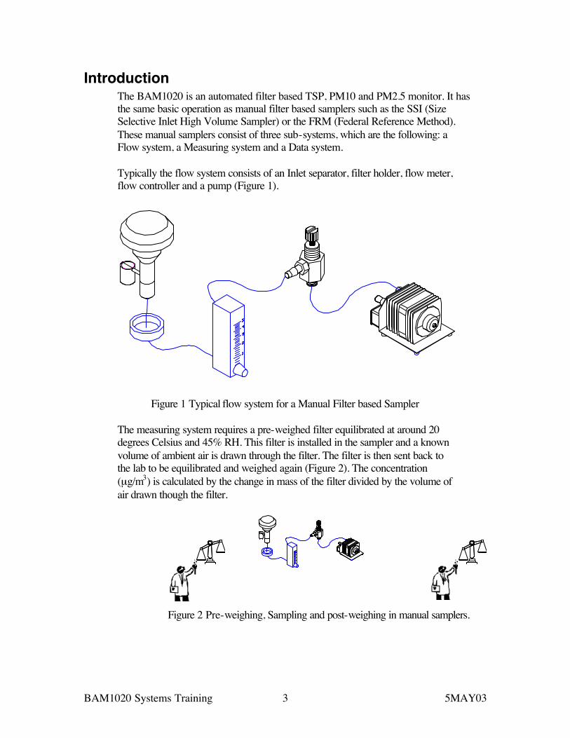
Introduction The BAM1020 is an automated filter based TSP, PM10 and PM2.5 monitor. It has the same basic operation as manual filter based samplers such as the SSI (Size Selective Inlet High Volume Sampler) or the FRM (Federal Reference Method). These manual samplers consist of three sub-systems, which are the following: a Flow system, a Measuring system and a Data system. Typically the flow system consists of an Inlet separator, filter holder, flow meter, flow controller and a pump (Figure 1).
Figure 1 Typical flow system for a Manual Filter based Sampler
The measuring system requires a pre-weighed filter equilibrated at around 20 degrees Celsius and 45% RH. This filter is installed in the sampler and a known volume of ambient air is drawn through the filter. The filter is then sent back to the lab to be equilibrated and weighed again (Figure 2). The concentration (µg/m3) is calculated by the change in mass of the filter divided by the volume of air drawn though the filter.
Figure 2 Pre-weighing, Sampling and post-weighing in manual samplers.

BAM1020 Systems Training 4 5MAY03
Finally, the data system tracks items such as the flow rate, filter and ambient temperature, barometric pressure, Wind speed and direction etc. These parameters are recorded with criteria to alert the user of invalid data.
Figure 3 Data collection system
The BAM1020 also has a flow system, measuring system and a data system. The advantage of the BAM1020 is in the automation of the measuring system and the simplification of both the data and flow systems. Each system can be independently audited to assure accurate data. The following sections give details on verifying the three systems of the BAM1020.
BAM1020 Systems Training 5 5MAY03
1 Flow System The flow system is the first of the three subsystems of the BAM1020. There are two tests to verify the performance of the flow system, which are a Leak Check and Flow Audit. Typically the main problem found in this system is nozzle material build up. The symptoms of this problem are negative concentration readings and a high flow check value. This problem can reoccur depending on the conditions of the sample air. A leak check should be done every month. A nozzle cleaning will need to done when a BAM fails a leak check and each time the filter tape is replaced.
A. Leak Check
Tools Required: BX-305 or BX-302 Silicone Lube
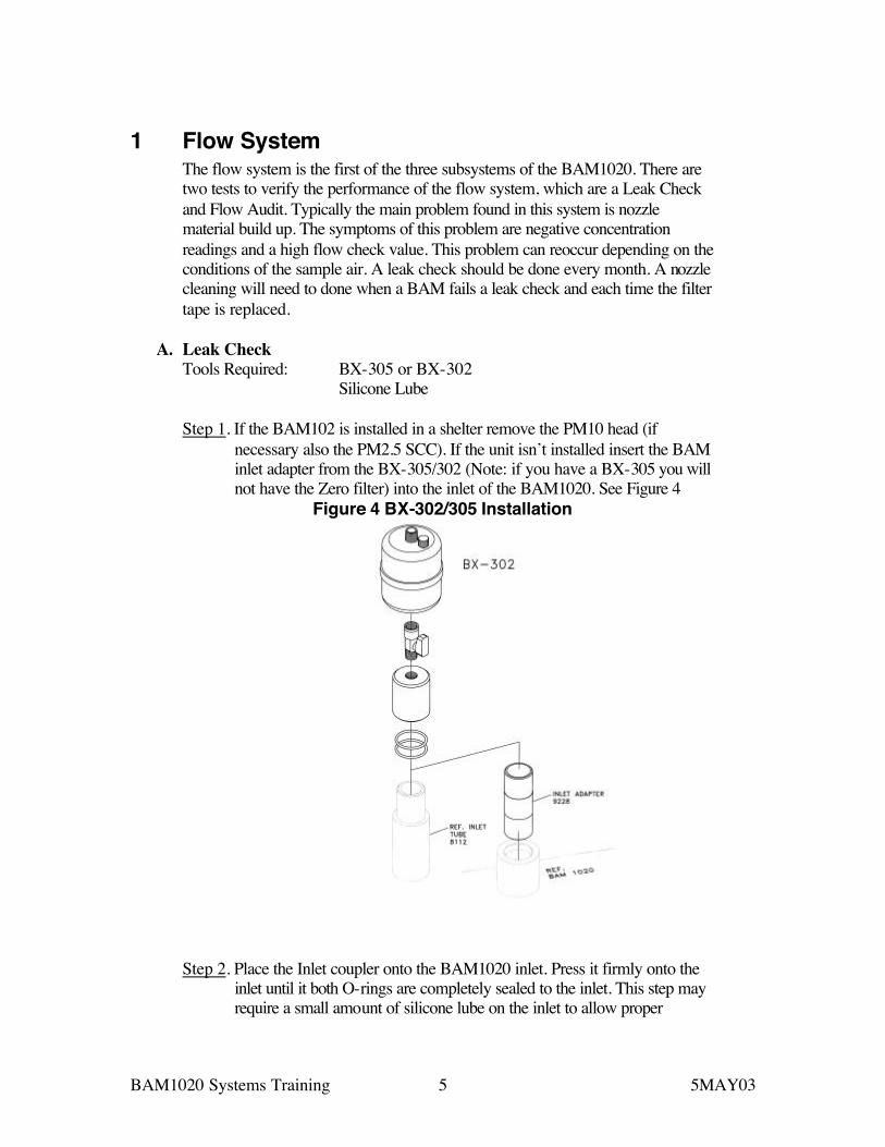
Step 1. If the BAM102 is installed in a shelter remove the PM10 head (if necessary also the PM2.5 SCC). If the unit isn’t installed insert the BAM inlet adapter from the BX-305/302 (Note: if you have a BX-305 you will not have the Zero filter) into the inlet of the BAM1020. See Figure 4
Figure 4 BX-302/305 Installation
Step 2. Place the Inlet coupler onto the BAM1020 inlet. Press it firmly onto the inlet until it both O-rings are completely sealed to the inlet. This step may require a small amount of silicone lube on the inlet to allow proper
BAM1020 Systems Training 6 5MAY03
sealing. Turn the stopcock valve to the off position. The lever will be at a 90-degree angle to the inlet tube.
Step 3. If the power to the BAM1020 is off turn it on now. Step 4. In the main menu press TEST. In the TEST menu select TAPE and
advance the tape one window. Step 5. From the main menu press TEST. In the TEST menu select PUMP and
turn the pump on. Step 6. The indicated flow rate should be less than 1.5 LPM. If the flow is greater
than 1.5 LPM see the Troubleshooting guide. Note: the reason that there is a 1.5 LPM flow allowance is due to the
nozzle filter paper interface. Under these test conditions the pressure differential across this interface is 21 inHg. This is an order of magnitude greater than the BAM1020 will encounter during sampling. If the flow is 1.5 LPM or less there will not be a leak during normal operation.
Step 7. Remove the Inlet coupler and replace the PM10 head and PM2.5 SCC. Troubleshooting
Step 1. Check the Zero on the Flow meter. a. Remove the pump tubing from the quick disconnect fitting on the back of
the BAM. b. From the main menu press TEST. In the TEST menu select PUMP and
turn the pump on. c. Flow should be less then 0.2 LPM. If the flow is greater than this value do
a flow audit from page 56-57 from manual. d. Retry the LEAK TEST PROCEDURE.
Step 2. Check all connections from the inlet adapter to the vacuum pump.
a. Remove the inlet adapter visually check for leaks and loose fittings and replace.
b. Remove the inlet tube from the BAM1020. Visually inspect for leaks or loose fittings and replace. Check the two orings in the BAM1020 inlet for wear or splits.
c. Open the front door on the BAM1020. Manually lift and lower the nozzle letting it slowly contact the filter paper. The nozzle should be free to move up and down. If the Nozzle sticks contact the factory and request a BX-308 kit.
d. Remove the tubing from the back of the BAM1020 and inspect for splits or loose connections. If the tube is split, cut out the bad portion and reinsert into the back of the BAM1020
e. Retry the LEAK TEST PROCEDURE.
Step 3. Clean the Nozzle. a. Tools Required – Cotton Swabs and ISO Alcohol. b. Remove the filter tape from the BAM1020 see section 4.7 of the manual. c. Lower the Nozzle.
BAM1020 Systems Training 7 5MAY03
a. In the BAM1020 main menu press TEST. In the TEST menu select PUMP and lower the nozzle.
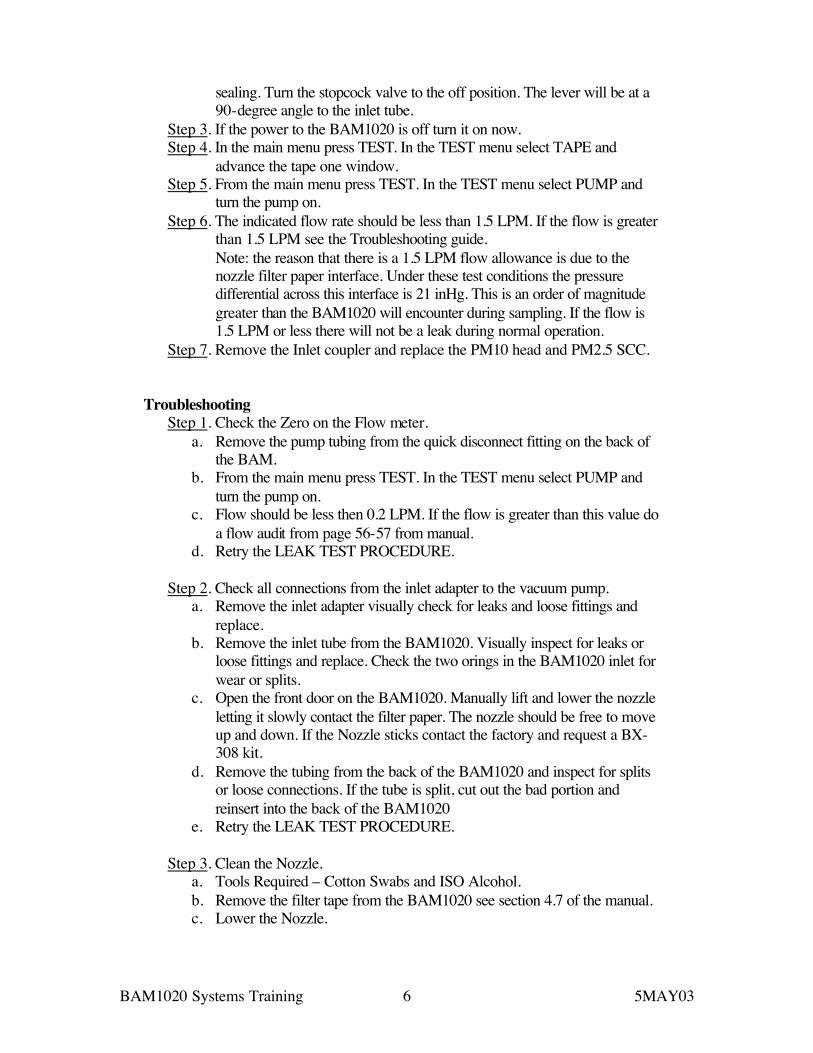
d. Lift the Nozzle by pressing with your thumb on the spring tensioner above the nozzle lip. Place a Cotton swab with ISO alcohol under the nozzle and lower the nozzle onto the cotton swab. Slowly rotate the Nozzle assembly. Eight to ten rotations will clean the nozzle. The Vane (this is the cross piece that sits under the filter paper where the nozzle contacts the filter paper) also needs to be cleaned. In the TEST PUMP screen lift the nozzle. The Vane can be viewed by removing the inlet tube and looking down the inlet tube while shining a flashlight into the nozzle/vane area. Use a sharp tool (dental pick) to gently scrape the outside of the vane to remove any filter paper build up. Next scrape the cross hair piece to remove any accumulation of paper see FIGURE 5 After scraping, flood the area with an alcohol drenched cotton applicator and clean the entire area.
Figure 5 Nozzle Cleaning Procedure
e. Retry the LEAK TEST PROCEDURES.
Step 4. Internal Check a. Tools required – Screwdriver set, Pliers, and Adjustable Wrench. b. Remove the Inlet tube from the BAM1020. c. Plug the inlet and check the flow. If the leak test passes, the leak is
in the inlet tube assembly. d. Remove the BAM1020 cover by 10 Philips head screws and gently
remove. e. Disconnect the tubing at the inline filter and plug the opening (see
Figure 6 ). Recheck the flow. If the unit passes the leak is in the nozzle assembly. Check all fittings from the inline filter to the BAM1020 inlet on the top of the BAM. Replace as needed. Note:

BAM1020 Systems Training 8 5MAY03
Figure 6 shows a BAM with filter temperature and RH option (BX-962).
Figure 6 Internal Fitting Check
If the leak is below the inline filter then the flow meter has a leak or is faulty. Replace with a new flow meter. MOI part number 970608
Disconnect and plug here.
BAM1020 Systems Training 9 5MAY03
B. Flow Audit/Calibration
1. ACTUAL flow type calibration requires a reference volumetric flow meter with a flow audit cap BX-305. For a complete list of BAM options see section 10.3.3 of the manual. Met One suggests the BIOS brand or purchasing the BX-307 option. Note: This screen becomes available in the Test menu when the ACTUAL flow type has been selected from the SETUP>CALIBRATE screen. Note: in older versions of the BAM1020 VOLUMETRIC is used for ACTUAL flow. The BAM must also be equipped with the volumetric flow hardware—BX-961. A Model 592 temperature sensor must be connected to the BAM back panel channel 6. Refer to APPENDIX F in the BAM manual for sensor hookup.
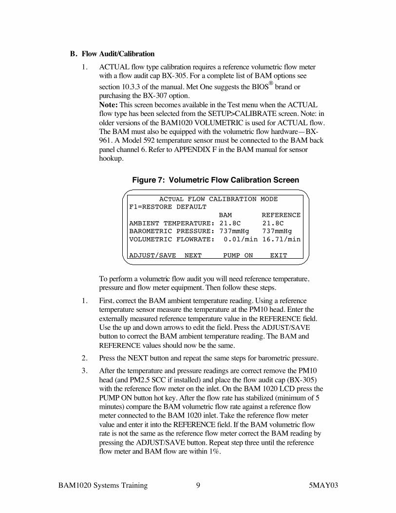
Figure 7: Volumetric Flow Calibration Screen
ACTUAL FLOW CALIBRATION MODE F1=RESTORE DEFAULT BAM REFERENCE AMBIENT TEMPERATURE: 21.8C 21.8C BAROMETRIC PRESSURE: 737mmHg 737mmHg VOLUMETRIC FLOWRATE: 0.0l/min 16.7l/min ADJUST/SAVE NEXT PUMP ON EXIT
To perform a volumetric flow audit you will need reference temperature, pressure and flow meter equipment. Then follow these steps.
1. First, correct the BAM ambient temperature reading. Using a reference temperature sensor measure the temperature at the PM10 head. Enter the externally measured reference temperature value in the REFERENCE field. Use the up and down arrows to edit the field. Press the ADJUST/SAVE button to correct the BAM ambient temperature reading. The BAM and REFERENCE values should now be the same.
2. Press the NEXT button and repeat the same steps for barometric pressure. 3. After the temperature and pressure readings are correct remove the PM10
head (and PM2.5 SCC if installed) and place the flow audit cap (BX-305) with the reference flow meter on the inlet. On the BAM 1020 LCD press the PUMP ON button hot key. After the flow rate has stabilized (minimum of 5 minutes) compare the BAM volumetric flow rate against a reference flow meter connected to the BAM 1020 inlet. Take the reference flow meter value and enter it into the REFERENCE field. If the BAM volumetric flow rate is not the same as the reference flow meter correct the BAM reading by pressing the ADJUST/SAVE button. Repeat step three until the reference flow meter and BAM flow are within 1%.
BAM1020 Systems Training 10 5MAY03
C. Inlet Heater
An option for the BAM1020 is the RH controlled heater. This option uses an RH sensor and a temperature sensor located below the filter paper. Testing has shown that if the RH on the filter paper increases above 55% the particulate can absorb water and the measured mass will increase. The RH controlled heater minimizes this effect. Met One suggests setting the RH value to 45%. This is the equilibration value for the FRM filters. Secondly, the filter temperature and ambient temperature are measured and a Delta-Temperature is computed from the difference. Volatile organic compounds (VOCs) and Semi-VOCs can be vaporized and removed from the measured mass if the filter temperature is greater than the ambient temperature by more than 5 degrees C. Met One suggest setting the Delta-T set point to 8 degrees Celsius. Note: Delta-T is only available if an ambient temperature probe (BX-592) is connected to channel 6. Heater is enabled if the BAM-1020 is on and the sample pump is on. The heater will turn off when RH is 1% below Setpoint or if the Delta-T Setpoint is reached.
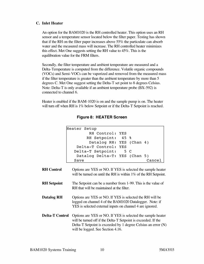
Figure 8: HEATER Screen
Heater Setup RH Control: YES RH Setpoint: 45 % Datalog RH: YES (Chan 4) Delta-T Control: YES Delta-T Setpoint: 5 C Datalog Delta-T: YES (Chan 5) Save Cancel
RH Control Options are YES or NO. If YES is selected the sample heater
will be turned on until the RH is within 1% of the RH Setpoint. RH Setpoint The Setpoint can be a number from 1-99. This is the value of
RH that will be maintained at the filter. Datalog RH Options are YES or NO. If YES is selected the RH will be
logged on channel 4 of the BAM1020 Datalogger. Note: if YES is selected external inputs on channel 4 are ignored.
Delta-T Control Options are YES or NO. If YES is selected the sample heater
will be turned off if the Delta-T Setpoint is exceeded. If the Delta-T Setpoint is exceeded by 1 degree Celsius an error (N) will be logged. See Section 4.16.
BAM1020 Systems Training 11 5MAY03
Delta-T Setpoint The Setpoint can be a number from 1-99. This is the value that if it is exceeded the sample heater will be turned off. Note: this overrides the RH Setpoint. If RH is still above the RH Setpoint but the Delta-T is equal or greater than Delta-T Setpoint the sample heater will be turned off.
Datalog Delta-T Options are YES or NO. If YES is selected the Delta-T will be
logged on channel 5 of the BAM1020 Datalogger. Note: if YES is selected external inputs on channel 5 are ignored.

BAM1020 Systems Training 12 5MAY03
2 Measuring System
A. Self Test
The BAM-1020 has a built-in self-test function. Press the TAPE key and then press the SELF TEST key. The Self-Test Menu is shown in Figure 9.
Figure 9: Self-Test Menu
02/08/1999 15:29:30LATCH: OFF TAPE BREAK: OKCAPSTAN: OK TAPE TENSION: OKNOZZLE DN: OK SHUTTLE: OKNOZZLE UP: OK REF EXTEND: OKFLOW: OK REF WITHDRAW: OKStatus: SELF TEST PASSEDTENSION SELF TEST EXIT
Upon depressing the SELF TEST key the will automatically go through a series of internal checks displaying, in sequence, the results of these checks. If the check passed, the user will see the word OK displayed, or if it does not operate correctly, the user will see the word FAIL displayed. With the large display it is not necessary to watch each segment being tested, as all of the results will be displayed upon completion of the test. The test will take approximately 4 minutes. The results of a properly operating unit are shown below. Explanation of each of the above functions;
LATCH
Checks the position of the pinch roller latch, if the LATCH is OFF then the capstan will engage the pinch roller. If the LATCH is ON the capstan will not be able to shuttle the filter tape. If the LATCH is ON during normal operation the error message will be shown on the display. See Figure 12 number 1 in the BAM manual.
CAPSTAN
Capstan operation is tested by moving the paper forward and then back, this test is keyed by proper operation of photo-interrupters. See Figure 12 number 6.
NOZZLE DN (DOWN)
Checks the nozzle movement and reports the proper operation of the ‘nozzle down’ photo-interrupter sensor.
NOZZLE UP
BAM1020 Systems Training 13 5MAY03
Checks the nozzle movement and reports the proper operation of the ‘nozzle up’ photo-interrupter sensor.
FLOW
The pump is turned on and the flow is tested, to verify operation for operation between 10-20 LPM.
TAPE BREAK
Detects broken tape by looking at the operation of the feed and take up motors photo interrupters. The motors are un-tensioned and then tensioned and the change in the photo interrupters.
TAPE TENSION
Checks the condition of the IDLER rollers, verifies operation of the photo interrupters on the tension idlers.
SHUTTLE
Moves the shuttle left and right and verifies correct operation using the photo interrupters.
REF (REFERENCE) EXTEND
Checks the reference membrane operation and verifies proper extension.
REF (REFERENCE) WITHDRAW Checks the reference membrane operation and verifies proper retraction.
B. Membrane Test
Test Calibration Mode The calibration test mode provides the operator the ability to perform a verification of the reference membrane calculation that occurs automatically every sample cycle. The same test could be performed in Count test mode, but without the mass density calculation. The Calibration test displays two beta counts, with and without the reference membrane. The reference membrane density m is then computed and displayed. Each BAM 1020 has an individually weighed membrane. This value is recorded in Appendix B as the ABS value. The calculated value from this procedure should be within 5% of the ABS value in Appendix B. Data is not logged. The total elapsed time is about 8.1 minutes. The Calibration Test Menu is shown in Figure 10.
BAM1020 Systems Training 14 5MAY03
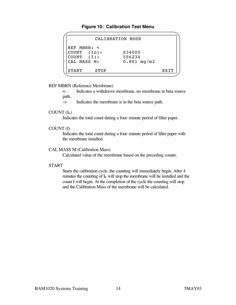
Figure 10: Calibration Test Menu
CALIBRATION MODE
REF MBRN: <COUNT (Io): 634000COUNT (I): 556234CAL MASS M: 0.801 mg/m3
START STOP EXIT
REF MBRN (Reference Membrane)
<- Indicates a withdrawn membrane, no membrane in beta source path. -> Indicates the membrane is in the beta source path.
COUNT (I0)
Indicates the total count during a four-minute period of filter paper. COUNT (I)
Indicates the total count during a four-minute period of filter paper with the membrane installed.
CAL MASS M (Calibration Mass)
Calculated value of the membrane based on the preceding counts. START
Starts the calibration cycle, the counting will immediately begin. After 4 minutes the counting of I0 will stop the membrane will be installed and the count I will begin. At the completion of the cycle the counting will stop and the Calibration Mass of the membrane will be calculated.
BAM1020 Systems Training 15 5MAY03
3 Data System
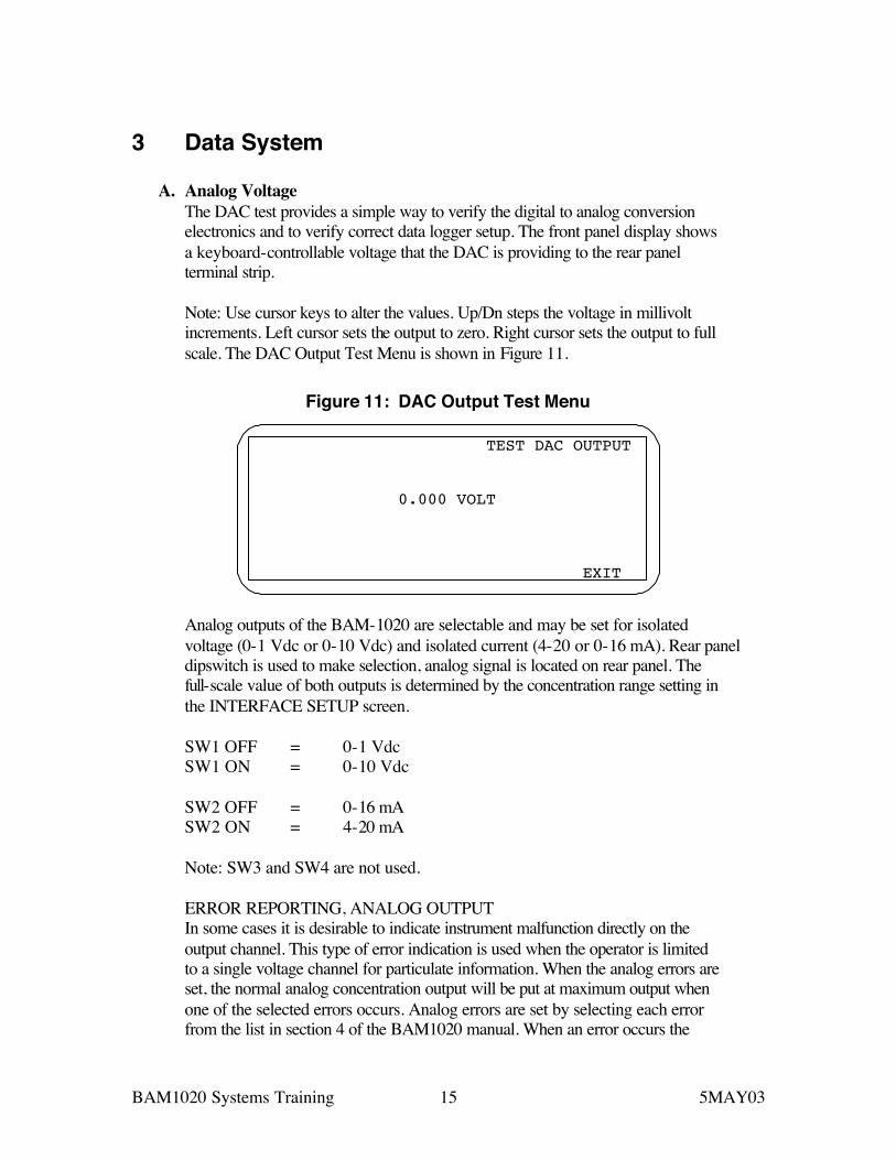
A. Analog Voltage The DAC test provides a simple way to verify the digital to analog conversion electronics and to verify correct data logger setup. The front panel display shows a keyboard-controllable voltage that the DAC is providing to the rear panel terminal strip. Note: Use cursor keys to alter the values. Up/Dn steps the voltage in millivolt increments. Left cursor sets the output to zero. Right cursor sets the output to full scale. The DAC Output Test Menu is shown in Figure 11.
Figure 11: DAC Output Test Menu
TEST DAC OUTPUT
0.000 VOLT
EXIT
Analog outputs of the BAM-1020 are selectable and may be set for isolated voltage (0-1 Vdc or 0-10 Vdc) and isolated current (4-20 or 0-16 mA). Rear panel dipswitch is used to make selection, analog signal is located on rear panel. The full-scale value of both outputs is determined by the concentration range setting in the INTERFACE SETUP screen. SW1 OFF = 0-1 Vdc SW1 ON = 0-10 Vdc SW2 OFF = 0-16 mA SW2 ON = 4-20 mA Note: SW3 and SW4 are not used. ERROR REPORTING, ANALOG OUTPUT In some cases it is desirable to indicate instrument malfunction directly on the output channel. This type of error indication is used when the operator is limited to a single voltage channel for particulate information. When the analog errors are set, the normal analog concentration output will be put at maximum output when one of the selected errors occurs. Analog errors are set by selecting each error from the list in section 4 of the BAM1020 manual. When an error occurs the
BAM1020 Systems Training 16 5MAY03
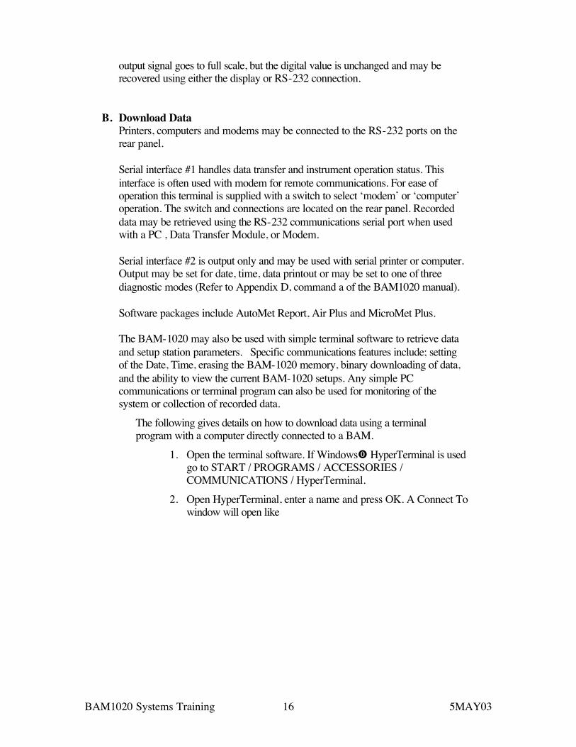
output signal goes to full scale, but the digital value is unchanged and may be recovered using either the display or RS-232 connection.
B. Download Data Printers, computers and modems may be connected to the RS-232 ports on the rear panel. Serial interface #1 handles data transfer and instrument operation status. This interface is often used with modem for remote communications. For ease of operation this terminal is supplied with a switch to select ‘modem’ or ‘computer’ operation. The switch and connections are located on the rear panel. Recorded data may be retrieved using the RS-232 communications serial port when used with a PC , Data Transfer Module, or Modem. Serial interface #2 is output only and may be used with serial printer or computer. Output may be set for date, time, data printout or may be set to one of three diagnostic modes (Refer to Appendix D, command a of the BAM1020 manual). Software packages include AutoMet Report, Air Plus and MicroMet Plus. The BAM-1020 may also be used with simple terminal software to retrieve data and setup station parameters. Specific communications features include; setting of the Date, Time, erasing the BAM-1020 memory, binary downloading of data, and the ability to view the current BAM-1020 setups. Any simple PC communications or terminal program can also be used for monitoring of the system or collection of recorded data.
The following gives details on how to download data using a terminal program with a computer directly connected to a BAM.
1. Open the terminal software. If Windows HyperTerminal is used go to START / PROGRAMS / ACCESSORIES / COMMUNICATIONS / HyperTerminal.
2. Open HyperTerminal, enter a name and press OK. A Connect To window will open like

BAM1020 Systems Training 17 5MAY03
Figure 12 HyperTerminal Connect to window.
3. Select the Com port that the BAM is connected to by using the drop down list from Figure 12. Press OK and that brings up
Figure 13 HyperTerminal communications protocol window.
In communications protocol window set the Bits per second window to match the setting on the BAM. Note: the default setting is 9600. The other settings are 8 data bits, NONE parity, 1 stop bit, and NONE for flow control. Press OK and the setup is complete.
4. In the HyperTerminal window press ENTER 6 times.
BAM1020 Systems Training 18 5MAY03
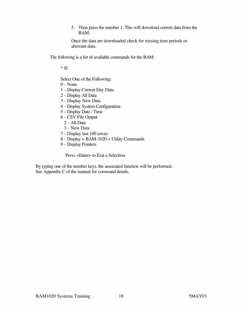
5. Then press the number 1. This will download current data from the BAM.
Once the data are downloaded check for missing time periods or aberrant data.
The following is a list of available commands for the BAM.
* H Select One of the Following: 0 - None 1 - Display Current Day Data 2 - Display All Data 3 - Display New Data 4 - Display System Configuration 5 - Display Date / Time 6 - CSV File Output 2 - All Data 3 - New Data 7 - Display last 100 errors 8 - Display > BAM-1020 < Utility Commands 9 - Display Pointers Press <Enter> to Exit a Selection
By typing one of the number keys, the associated function will be performed. See Appendix C of the manual for command details.