ball - Шинэ Эрин ОУС
TRANSCRIPT

10
9702/42/O/N/19© UCLES 2019
4 A ball of mass M is held on a horizontal surface by two identical extended springs, as illustrated in Fig. 4.1.
ballmass M oscillator
fixedpoint
Fig. 4.1
One spring is attached to a fixed point. The other spring is attached to an oscillator.
The oscillator is switched off. The ball is displaced sideways along the axis of the springs and is then released. The variation with time t of the displacement x of the ball is shown in Fig. 4.2.
–1.5
–1.0
–0.5
0
0.5
1.0
1.5
0.40 0.8 1.2 1.6 2.0 2.4t / s
x / cm
Fig. 4.2
(a) State:
(i) what is meant by damping
...........................................................................................................................................
..................................................................................................................................... [1]
(ii) the evidence provided by Fig. 4.2 that the motion of the ball is damped.
...........................................................................................................................................
..................................................................................................................................... [1]

11
9702/42/O/N/19© UCLES 2019 [Turn over
(b) The acceleration a and the displacement x of the ball are related by the expression
– 2a Mk x= c m
where k is the spring constant of one of the springs.
The mass M of the ball is 1.2 kg.
(i) Use data from Fig. 4.2 to determine the angular frequency ω of the oscillations of the ball.
ω = .............................................. rad s–1 [2]
(ii) Use your answer in (i) to determine the value of k.
k = ............................................... N m–1 [2]
12
9702/42/O/N/19© UCLES 2019
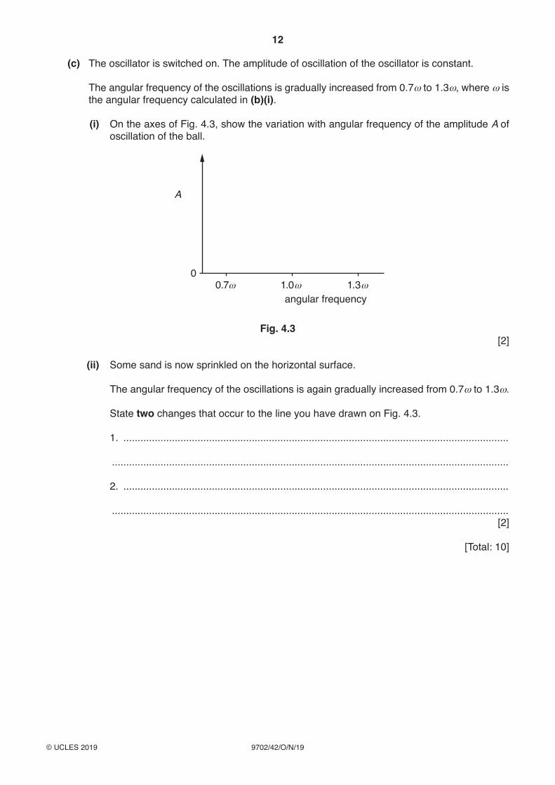
(c) The oscillator is switched on. The amplitude of oscillation of the oscillator is constant.
Theangularfrequencyoftheoscillationsisgraduallyincreasedfrom0.7ω to 1.3ω, where ω is the angular frequency calculated in (b)(i).
(i) On the axes of Fig. 4.3, show the variation with angular frequency of the amplitude A of oscillation of the ball.
A
00.7ω 1.0
angular frequencyω 1.3ω
Fig. 4.3 [2]
(ii) Some sand is now sprinkled on the horizontal surface.
Theangularfrequencyoftheoscillationsisagaingraduallyincreasedfrom0.7ω to 1.3ω.
State two changes that occur to the line you have drawn on Fig. 4.3.
1. .......................................................................................................................................
...........................................................................................................................................
2. .......................................................................................................................................
........................................................................................................................................... [2]
[Total: 10]
8
9702/42/F/M/20© UCLES 2020
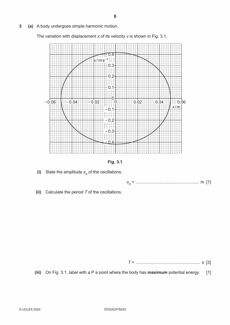
3 (a) A body undergoes simple harmonic motion.
The variation with displacement x of its velocity v is shown in Fig. 3.1.
0.1
0
– 0.1
– 0.02 0 0.02 0.04 0.06x / m
v / m s–1
– 0.04– 0.06
– 0.2
– 0.3
– 0.4
0.2
0.3
0.4
Fig. 3.1
(i) State the amplitude xo of the oscillations.
xo = ..................................................... m [1]
(ii) Calculate the period T of the oscillations.
T = ...................................................... s [3]
(iii) On Fig. 3.1, label with a P a point where the body has maximum potential energy. [1]

9
9702/42/F/M/20© UCLES 2020 [Turn over
(b) A bar magnet is suspended from the free end of a spring, as shown in Fig. 3.2.
spring
magnet
coil
Fig. 3.2
One pole of the magnet is situated in a coil of wire. The coil is connected in series with a switch and a resistor. The switch is open.
The magnet is displaced vertically and then released. The magnet oscillates with simple harmonic motion.
(i) State Faraday’s law of electromagnetic induction.
...........................................................................................................................................
...........................................................................................................................................
...........................................................................................................................................
..................................................................................................................................... [2]
(ii) The switch is now closed. Explain why the oscillations of the magnet are damped.
...........................................................................................................................................
...........................................................................................................................................
...........................................................................................................................................
...........................................................................................................................................
...........................................................................................................................................
..................................................................................................................................... [3]
[Total: 10]

8
9702/42/F/M/19© UCLES 2019
3 A cylindrical tube, sealed at one end, has cross-sectional area A and contains some sand. The total mass of the tube and the sand is M.
The tube floats upright in a liquid of density ρ, as illustrated in Fig. 3.1.
equilibrium positionof base of tube
tubecross-sectionalarea A
liquiddensity ρ
x
sand
Fig. 3.1
The tube is pushed a short distance into the liquid and then released.
(a) (i) State the two forces that act on the tube immediately after its release.
...........................................................................................................................................
...................................................................................................................................... [1]
(ii) State and explain the direction of the resultant force acting on the tube immediately after its release.
...........................................................................................................................................
...........................................................................................................................................
...................................................................................................................................... [2]
(b) The acceleration a of the tube is given by the expression
a = – AρgM x
where x is the vertical displacement of the tube from its equilibrium position.
Use the expression to explain why the tube undergoes simple harmonic oscillations in the liquid.
...................................................................................................................................................
...................................................................................................................................................
.............................................................................................................................................. [2]

9
9702/42/F/M/19© UCLES 2019 [Turn over
(c) For a tube having cross-sectional area A of 4.5 cm2 and a total mass M of 0.17 kg, the period of oscillation of the tube is 1.3 s.
(i) Determine the angular frequency ω of the oscillations.
ω = ................................................ rad s–1 [2]
(ii) Use your answer in (i) and the expression in (b) to determine the density ρ of the liquid in which the tube is floating.
ρ = ................................................ kg m–3 [3]
[Total: 10]

8
9702/42/M/J/20© UCLES 2020
4 A dish is made from a section of a hollow glass sphere.
The dish, fixed to a horizontal table, contains a small solid ball of mass 45 g, as shown in Fig. 4.1.
C
ballmass 45 g
surface of dish
x
Fig. 4.1
The horizontal displacement of the ball from the centre C of the dish is x.
Initially, the ball is held at rest with distance x = 3.0 cm.
The ball is then released. The variation with time t of the horizontal displacement x of the ball from point C is shown in Fig. 4.2.
–4
–2
–3
0
–1
2
1
x / cm
t / s
3
4
10 2 3 4 765
Fig. 4.2
The motion of the ball in the dish is simple harmonic with its acceleration a given by the expression
a = –(gR) x
where g is the acceleration of free fall and R is a constant that depends on the dimensions of the dish and the ball.

9
9702/42/M/J/20© UCLES 2020 [Turn over
(a) Use Fig. 4.2 to show that the angular frequency ω of oscillation of the ball in the dish is 2.9 rad s–1.
[1]
(b) Use the information in (a) to:
(i) determine R
R = ..................................................... m [2]
(ii) calculate the speed of the ball as it passes over the centre C of the dish.
speed = ................................................ m s–1 [2]
(c) Some moisture collects on the surface of the dish so that the motion of the ball becomes lightly damped.
On the axes of Fig. 4.2, draw a line to show the lightly damped motion of the ball for the first 5.0 s after the release of the ball. [3]
[Total: 8]

8
9702/42/M/J/17© UCLES 2017
3 A bar magnet of mass 250 g is suspended from the free end of a spring, as illustrated in Fig. 3.1.
spring
magnet
coil
Fig. 3.1
The magnet hangs so that one pole is near the centre of a coil of wire.
The coil is connected in series with a resistor and a switch. The switch is open.
The magnet is displaced vertically and then allowed to oscillate with one pole remaining inside the coil. The other pole remains outside the coil.
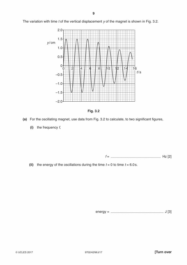
At time t = 0, the magnet is oscillating freely as it passes through its equilibrium position. At time t = 6.0 s, the switch in the circuit is closed.
9
9702/42/M/J/17© UCLES 2017 [Turn over
The variation with time t of the vertical displacement y of the magnet is shown in Fig. 3.2.
–2.0
–1.5
–1.0
–0.5
0
0.5
1.0
y / cm1.5
2.0
0 2 4 6 8 10 12 14 16t / s
Fig. 3.2
(a) For the oscillating magnet, use data from Fig. 3.2 to calculate, to two significant figures,
(i) the frequency f,
f = .................................................... Hz [2]
(ii) the energy of the oscillations during the time t = 0 to time t = 6.0 s.
energy = ....................................................... J [3]

10
9702/42/M/J/19© UCLES 2019
3 A spring is hung vertically from a fixed point. A mass M is hung from the other end of the spring, as illustrated in Fig. 3.1.
L
mass M
spring
Fig. 3.1
The mass is displaced downwards and then released. The subsequent motion of the mass is simple harmonic.
The variation with time t of the length L of the spring is shown in Fig. 3.2.
1.00 0.2 0.4 0.6 0.8
t / s
8
10
12
14
16
L / cm
Fig. 3.2
(a) State:
(i) one time at which the mass is moving with maximum speed
time = ..................................................... s [1]
(ii) one time at which the spring has maximum elastic potential energy.
time = ...................................................... s [1]

11
9702/42/M/J/19© UCLES 2019 [Turn over
(b) Use data from Fig. 3.2 to determine, for the motion of the mass:
(i) the angular frequency ω
ω = .............................................. rad s–1 [2]
(ii) the maximum speed
maximum speed = ................................................ m s–1 [2]
(iii) the magnitude of the maximum acceleration.
maximum acceleration = ................................................ m s–2 [2]

12
9702/42/M/J/19© UCLES 2019
(c) The mass M is now suspended from two springs, each identical to that in Fig. 3.1, as shown in Fig. 3.3.
mass M
Fig. 3.3
Suggest and explain the change, if any, in the period of oscillation of the mass. A numerical answer is not required.
...................................................................................................................................................
...................................................................................................................................................
...............................................................................................................................................[2]
[Total: 10]

8
9702/42/O/N/17© UCLES 2017
3 (a) (i) Define the radian.
...........................................................................................................................................
...........................................................................................................................................
.......................................................................................................................................[2]
(ii) State, by reference to simple harmonic motion, what is meant by angular frequency.
...........................................................................................................................................
.......................................................................................................................................[1]
(b) A thin metal strip, clamped horizontally at one end, has a load of mass M attached to its free end, as shown in Fig. 3.1.
L
x
loadmass M
metal striposcillationof load
clamp
Fig. 3.1
The metal strip bends, as shown in Fig. 3.1.
When the free end of the strip is displaced vertically and then released, the mass oscillates in a vertical plane.
Theory predicts that the variation of the acceleration a of the oscillating load with the displacement x from its equilibrium position is given by
a = – ML
c3c m x
where L is the effective length of the metal strip and c is a positive constant.
(i) Explain how the expression shows that the load is undergoing simple harmonic motion.
...........................................................................................................................................
...........................................................................................................................................
...........................................................................................................................................
.......................................................................................................................................[2]

9
9702/42/O/N/17© UCLES 2017 [Turn over
(ii) For a metal strip of length L = 65 cm and a load of mass M = 240 g, the frequency of oscillation is 3.2 Hz.
Calculate the constant c.
c = ........................................... kg m3 s–2 [3]
[Total: 8]

10
9702/42/O/N/18© UCLES 2018
4 A U-tube contains liquid, as shown in Fig. 4.1.
liquid
L
xx
Fig. 4.1 Fig. 4.2
The total length of the liquid column is L.
The column of liquid is displaced so that the change in height of the liquid level from the equilibrium position in each arm of the U-tube is x, as shown in Fig. 4.2.
The liquid in the U-tube then oscillates such that its acceleration a is given by the expression
a Lg
x2
=-d n
where g is the acceleration of free fall.
(a) Show that the liquid column undergoes simple harmonic motion.
[2]

11
9702/42/O/N/18© UCLES 2018 [Turn over
(b) The variation with time t of the displacement x is shown in Fig. 4.3.
–2.0
–1.0
0
+1.0
+2.0
x / cm
0 0.25 0.50 0.75 1.00 1.25 1.50t / s
Fig. 4.3
Use data from Fig. 4.3 to determine the length L of the liquid column.
L = ...................................................... m [3]

12
9702/42/O/N/18© UCLES 2018
(c) The oscillations shown in Fig. 4.3 are damped.
(i) Suggest one cause of this damping.
...........................................................................................................................................
.......................................................................................................................................[1]
(ii) Calculate the ratio
total energy of oscillations after 1.5 complete oscillations
total initial energy of oscillations
ratio = .......................................................... [2]
[Total: 8]

10
9702/42/M/J/18© UCLES 2018
4 (a) State two conditions necessary for a mass to be undergoing simple harmonic motion.
1. ...............................................................................................................................................
...................................................................................................................................................
2. ...............................................................................................................................................
................................................................................................................................................... [2]
(b) A trolley of mass 950 g is held on a horizontal surface by means of two springs attached to fixed points P and Q, as shown in Fig. 4.1.
QP
trolleymass 950 g spring
Fig. 4.1
The springs, each having a spring constant k of 230 N m–1, are always extended.
The trolley is displaced along the line of the springs and then released. The variation with time t of the displacement x of the trolley is shown in Fig. 4.2.
00
x
t1 t
Fig. 4.2

11
9702/42/M/J/18© UCLES 2018 [Turn over
(i) 1. State and explain whether the oscillations of the trolley are heavily damped, critically damped or lightly damped.
....................................................................................................................................
....................................................................................................................................
2. Suggest the cause of the damping.
....................................................................................................................................
....................................................................................................................................
.................................................................................................................................... [3]
(ii) The acceleration a of the trolley of mass m may be assumed to be given by the expression
a = – mk x2d n .
1. Calculate the angular frequency ω of the oscillations of the trolley.
ω = ............................................... rad s–1 [3]
2. Determine the time t1 shown on Fig. 4.2.
t1 = ....................................................... s [2]
[Total: 10]

8
9702/42/O/N/16© UCLES 2016
4 A mass hangs vertically from a fixed point by means of a spring, as shown in Fig. 4.1.
spring
mass
l
Fig. 4.1
The mass is displaced vertically and then released. The subsequent oscillations of the mass are simple harmonic.
The variation with time t of the length l of the spring is shown in Fig. 4.2.
0.112
14
16
18
t / s
13
15
17
0.20 0.3 0.4 0.5 0.6
l / cm
Fig. 4.2
(a) Use Fig. 4.2 to
(i) state two values of t at which the mass is moving downwards with maximum speed,
t = ................................. s and t = ................................. s [1]

9
9702/42/O/N/16© UCLES 2016 [Turn over
(ii) determine, for these oscillations, the angular frequency ω,
ω = .............................................. rad s–1 [2]
(iii) show that the maximum speed of the mass is 0.42 m s–1.
[2]
(b) Use data from Fig. 4.2 and (a)(iii) to sketch, on the axes of Fig. 4.3, the variation with displacement x from the equilibrium position of the velocity v of the mass.
0.5
0.1
–0.1
–0.2
–0.3
–0.4
–0.5
0.2
0.3
0.4
–4 –3 –2 –1 00
1 2 3 4x / cm
v / m s–1
Fig. 4.3 [3]
[Total: 8]
8
9702/42/M/J/16© UCLES 2016
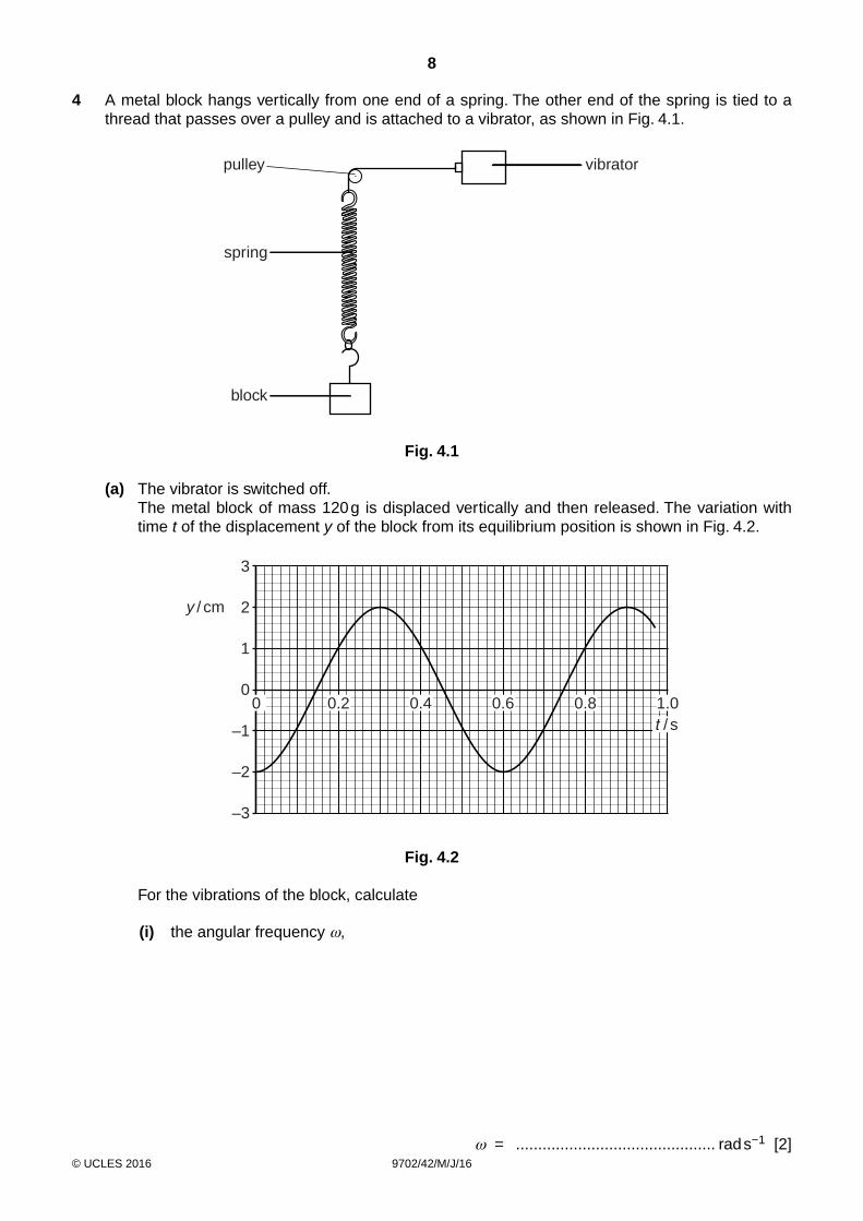
4 A metal block hangs vertically from one end of a spring. The other end of the spring is tied to a thread that passes over a pulley and is attached to a vibrator, as shown in Fig. 4.1.
spring
block
pulley vibrator
Fig. 4.1
(a) The vibrator is switched off. The metal block of mass 120 g is displaced vertically and then released. The variation with
time t of the displacement y of the block from its equilibrium position is shown in Fig. 4.2.
–3
–2
–1
0
1
2y / cm
3
0 0.2 0.4 0.6 0.8 1.0 / s
Fig. 4.2
For the vibrations of the block, calculate
(i) the angular frequency ω,
ω = ............................................. rad s−1 [2]

9
9702/42/M/J/16© UCLES 2016 [Turn over
(ii) the energy of the vibrations.
energy = ...................................................... J [2]
(b) The vibrator is now switched on.
The frequency of vibration is varied from 0.7f to 1.3f where f is the frequency of vibration of the block in (a).
For the block, complete Fig. 4.3 to show the variation with frequency of the amplitude of vibration. Label this line A. [3]
0
amplitude
0.7 1.3frequency
Fig. 4.3
(c) Some light feathers are now attached to the block in (b) to increase air resistance.
The frequency of vibration is once again varied from 0.7f to 1.3f. The new amplitude of vibration is measured for each frequency.
On Fig. 4.3, draw a line to show the variation with frequency of the amplitude of vibration. Label this line B. [2]
[Total: 9]