baldor mn406 rpm ac inverter duty motors … mn406 rpm ac inverter duty motors operating manual …
TRANSCRIPT

BALDOR MN406 RPM AC Inverter Duty Motors Operatingmanual http://www.manuallib.com/baldor/mn406-rpm-ac-inverter-duty-motors-operating-manual.html
This manual contains general procedures that apply to BaldorReliance Motor products. Be sure toread and understand the Safety Notice statements in this manual. For your protection, do not install,operate or attempt to perform maintenance procedures until you understand the Warning andCautionstatements.
ManualLib.com collects and classifies the global productinstrunction manuals to help users access anytime andanywhere, helping users make better use of products.
http://www.manuallib.com

RPM AC Inverter Duty MotorsNEMA Frames FL180 − L440 FamilyIEC Frames FDL112− DL280 Family
(Specifically designed for operation with Adjustable Speed Controls)
Installation & Operating Manual
3/09 MN406
This Manual:http://www.manuallib.com/baldor/mn406-rpm-ac-inverter-duty-motors-operating-manual.html

Any trademarks used in this manual are the property of their respective owners.
This Manual:http://www.manuallib.com/baldor/mn406-rpm-ac-inverter-duty-motors-operating-manual.html

Table of Contents
Table of Contents iMN406
Section 1General Information 1−1. . . . . . . . . . . . . . . . . . . . . . . . . . . . . . . . . . . . . . . . . . . . . . . . . . . . . . . . . . . . . . . . . . . . . . . . . . . . . .
Overview 1−1. . . . . . . . . . . . . . . . . . . . . . . . . . . . . . . . . . . . . . . . . . . . . . . . . . . . . . . . . . . . . . . . . . . . . . . . . . . . . . . . . . . .
Limited Warranty 1−1. . . . . . . . . . . . . . . . . . . . . . . . . . . . . . . . . . . . . . . . . . . . . . . . . . . . . . . . . . . . . . . . . . . . . . . . . . . . . .
Safety Notice 1−1. . . . . . . . . . . . . . . . . . . . . . . . . . . . . . . . . . . . . . . . . . . . . . . . . . . . . . . . . . . . . . . . . . . . . . . . . . . . . . . . .
Receiving 1−3. . . . . . . . . . . . . . . . . . . . . . . . . . . . . . . . . . . . . . . . . . . . . . . . . . . . . . . . . . . . . . . . . . . . . . . . . . . . . . . . . . . .
Handling 1−3. . . . . . . . . . . . . . . . . . . . . . . . . . . . . . . . . . . . . . . . . . . . . . . . . . . . . . . . . . . . . . . . . . . . . . . . . . . . . . . . . . . . .
Storage 1−3. . . . . . . . . . . . . . . . . . . . . . . . . . . . . . . . . . . . . . . . . . . . . . . . . . . . . . . . . . . . . . . . . . . . . . . . . . . . . . . . . . . . . .
Removal From Storage 1−4. . . . . . . . . . . . . . . . . . . . . . . . . . . . . . . . . . . . . . . . . . . . . . . . . . . . . . . . . . . . . . . . . . . . . . . .
Section 2Installation & Operation 2−1. . . . . . . . . . . . . . . . . . . . . . . . . . . . . . . . . . . . . . . . . . . . . . . . . . . . . . . . . . . . . . . . . . . . . . . . . . .
Overview 2−1. . . . . . . . . . . . . . . . . . . . . . . . . . . . . . . . . . . . . . . . . . . . . . . . . . . . . . . . . . . . . . . . . . . . . . . . . . . . . . . . . . . .
Mechanical Installation 2−1. . . . . . . . . . . . . . . . . . . . . . . . . . . . . . . . . . . . . . . . . . . . . . . . . . . . . . . . . . . . . . . . . . . . . . . . .
Stub Shaft Installation 2−2. . . . . . . . . . . . . . . . . . . . . . . . . . . . . . . . . . . . . . . . . . . . . . . . . . . . . . . . . . . . . . . . . . . . .
Stub Shaft Removal 2−2. . . . . . . . . . . . . . . . . . . . . . . . . . . . . . . . . . . . . . . . . . . . . . . . . . . . . . . . . . . . . . . . . . . . . . .
Mounting Location 2−2. . . . . . . . . . . . . . . . . . . . . . . . . . . . . . . . . . . . . . . . . . . . . . . . . . . . . . . . . . . . . . . . . . . . . . . .
Alignment 2−3. . . . . . . . . . . . . . . . . . . . . . . . . . . . . . . . . . . . . . . . . . . . . . . . . . . . . . . . . . . . . . . . . . . . . . . . . . . . . . . . . . . .
Doweling & Bolting 2−3. . . . . . . . . . . . . . . . . . . . . . . . . . . . . . . . . . . . . . . . . . . . . . . . . . . . . . . . . . . . . . . . . . . . . . . . . . . .
Guarding 2−4. . . . . . . . . . . . . . . . . . . . . . . . . . . . . . . . . . . . . . . . . . . . . . . . . . . . . . . . . . . . . . . . . . . . . . . . . . . . . . . . . . . . .
Electrical Installation 2−4. . . . . . . . . . . . . . . . . . . . . . . . . . . . . . . . . . . . . . . . . . . . . . . . . . . . . . . . . . . . . . . . . . . . . . . . . . .
Thermostat Leads Connection 2−5. . . . . . . . . . . . . . . . . . . . . . . . . . . . . . . . . . . . . . . . . . . . . . . . . . . . . . . . . . . . . .
Blower Motor Connection 2−5. . . . . . . . . . . . . . . . . . . . . . . . . . . . . . . . . . . . . . . . . . . . . . . . . . . . . . . . . . . . . . . . . .
Grounding 2−5. . . . . . . . . . . . . . . . . . . . . . . . . . . . . . . . . . . . . . . . . . . . . . . . . . . . . . . . . . . . . . . . . . . . . . . . . . . . . . .
Shipping Blocks 2−6. . . . . . . . . . . . . . . . . . . . . . . . . . . . . . . . . . . . . . . . . . . . . . . . . . . . . . . . . . . . . . . . . . . . . . . . . .
Encoder Connections 2−6. . . . . . . . . . . . . . . . . . . . . . . . . . . . . . . . . . . . . . . . . . . . . . . . . . . . . . . . . . . . . . . . . . . . . .
Drain Plugs 2−6. . . . . . . . . . . . . . . . . . . . . . . . . . . . . . . . . . . . . . . . . . . . . . . . . . . . . . . . . . . . . . . . . . . . . . . . . . . . . .
Drive 2−6. . . . . . . . . . . . . . . . . . . . . . . . . . . . . . . . . . . . . . . . . . . . . . . . . . . . . . . . . . . . . . . . . . . . . . . . . . . . . . . . . . . . . . . .
Shaft Loads − Axial and Radial 2−7. . . . . . . . . . . . . . . . . . . . . . . . . . . . . . . . . . . . . . . . . . . . . . . . . . . . . . . . . . . . . . . . . .
Optional Accessories 2−8. . . . . . . . . . . . . . . . . . . . . . . . . . . . . . . . . . . . . . . . . . . . . . . . . . . . . . . . . . . . . . . . . . . . . . . . . .
First Time Start Up 2−9. . . . . . . . . . . . . . . . . . . . . . . . . . . . . . . . . . . . . . . . . . . . . . . . . . . . . . . . . . . . . . . . . . . . . . . . . . . .
Air Flow Volume 2−9. . . . . . . . . . . . . . . . . . . . . . . . . . . . . . . . . . . . . . . . . . . . . . . . . . . . . . . . . . . . . . . . . . . . . . . . . . . . . . .
Operation 2−10. . . . . . . . . . . . . . . . . . . . . . . . . . . . . . . . . . . . . . . . . . . . . . . . . . . . . . . . . . . . . . . . . . . . . . . . . . . . . . . . . . . .
Maximum Safe Speed 2−10. . . . . . . . . . . . . . . . . . . . . . . . . . . . . . . . . . . . . . . . . . . . . . . . . . . . . . . . . . . . . . . . . . . . .
Balance 2−10. . . . . . . . . . . . . . . . . . . . . . . . . . . . . . . . . . . . . . . . . . . . . . . . . . . . . . . . . . . . . . . . . . . . . . . . . . . . . . . . .
Section 3Maintenance & Troubleshooting 3−1. . . . . . . . . . . . . . . . . . . . . . . . . . . . . . . . . . . . . . . . . . . . . . . . . . . . . . . . . . . . . . . . . . .
General Inspection 3−1. . . . . . . . . . . . . . . . . . . . . . . . . . . . . . . . . . . . . . . . . . . . . . . . . . . . . . . . . . . . . . . . . . . . . . . . . . . .
Relubrication & Bearings 3−1. . . . . . . . . . . . . . . . . . . . . . . . . . . . . . . . . . . . . . . . . . . . . . . . . . . . . . . . . . . . . . . . . . . . . . .
Lubrication Procedure 3−1. . . . . . . . . . . . . . . . . . . . . . . . . . . . . . . . . . . . . . . . . . . . . . . . . . . . . . . . . . . . . . . . . . . . .
Type of Grease 3−2. . . . . . . . . . . . . . . . . . . . . . . . . . . . . . . . . . . . . . . . . . . . . . . . . . . . . . . . . . . . . . . . . . . . . . . . . . .
Troubleshooting Chart 3−3. . . . . . . . . . . . . . . . . . . . . . . . . . . . . . . . . . . . . . . . . . . . . . . . . . . . . . . . . . . . . . . . . . . . . . . . .
Suggested bearing and winding RTD setting guidelines for Non−Hazardous Locations ONLY 3−4. . . . . . . . . . . .
This Manual:http://www.manuallib.com/baldor/mn406-rpm-ac-inverter-duty-motors-operating-manual.html

Section 1General Information
ii Table of Contents MN406
This Manual:http://www.manuallib.com/baldor/mn406-rpm-ac-inverter-duty-motors-operating-manual.html

Section 1General Information
General Information 1−1MN406
Overview This manual contains general procedures that apply to Baldor�Reliance Motor products. Be sure to read andunderstand the Safety Notice statements in this manual. For your protection, do not install, operate or attemptto perform maintenance procedures until you understand the Warning and Caution statements. A Warning statement indicates a possible unsafe condition that can cause harm to personnel. A Caution statement indicates a condition that can cause damage to equipment.
Important: This instruction manual is not intended to include a comprehensive listing of all details for allprocedures required for installation, operation and maintenance. This manual describes generalguidelines that apply to most of the motor products shipped by Baldor. If you have a questionabout a procedure or are uncertain about any detail, Do Not Proceed. Please contact your Baldor District office for more information or clarification.Before you install, operate or perform maintenance, become familiar with the following if applicable toyour area:
� NEMA Publication MG-2, Safety Standard for Construction and guide for Selection, Installation and Use of Electric Motors and Generators.
� IEC 34−1 Electrical and IEC72−1 Mechanical specifications� ANSI C51.5, the National Electrical Code (NEC) and local codes and practices.
Limited Warrantywww.baldor.com/support/warranty_standard.as
Safety Notice: This equipment contains high voltage! Electrical shock can cause serious or fatal injury. Only qualified personnel should attempt installation, operation and maintenance of electrical equipment.Be sure that you are completely familiar with NEMA publication MG-2, safety standards for construction andguide for selection, installation and use of electric motors and generators, the National Electrical Code andlocal codes and practices. Unsafe installation or use can cause conditions that lead to serious or fatal injury.Only qualified personnel should attempt the installation, operation and maintenance of this equipment.
WARNING: Do not touch electrical connections before you first ensure that power has been disconnected.Electrical shock can cause serious or fatal injury. Only qualified personnel should attempt theinstallation, operation and maintenance of this equipment.
WARNING: Disconnect all electrical power from the motor windings and accessory devices beforedisassembly of the motor. Electrical shock can cause serious or fatal injury.
WARNING: The Adjustable Speed Controller may apply hazardous voltages to the motor leads after power tothe controller has been turned off. Verify that the controller is incapable of delivering hazardousvoltages and that the voltage at the motor leads is zero before proceeding. Failure to observe thisprecaution may result in severe bodily injury or death.
WARNING: Be sure the system is properly grounded before applying power. Do not apply AC power beforeyou ensure that all grounding instructions have been followed. Electrical shock can causeserious or fatal injury. National Electrical Code and Local codes must be carefully followed.
WARNING: Avoid extended exposure to machinery with high noise levels. Be sure to wear ear protectivedevices to reduce harmful effects to your hearing.
WARNING: Surface temperatures of motor enclosures may reach temperatures which can cause discomfortor injury to personnel accidentally coming into contact with hot surfaces. When installing,protection should be provided by the user to protect against accidental contact with hot surfaces.Failure to observe this precaution could result in bodily injury.
WARNING: This equipment may be connected to other machinery that has rotating parts or parts that aredriven by this equipment. Improper use can cause serious or fatal injury. Only qualifiedpersonnel should attempt to install operate or maintain this equipment.
WARNING: Do not by-pass or disable protective devices or safety guards. Safety features are designed toprevent damage to personnel or equipment. These devices can only provide protection if theyremain operative.
WARNING: Avoid the use of automatic reset devices if the automatic restarting of equipment can behazardous to personnel or equipment.
WARNING: Be sure the load is properly coupled to the motor shaft before applying power. The shaft keymust be fully captive by the load device. Improper coupling can cause harm to personnel orequipment if the load decouples from the shaft during operation.
WARNING: Use proper care and procedures that are safe during handling, lifting, installing, operating andmaintaining operations. Improper methods may cause muscle strain or other harm.
WARNING: Incorrect motor rotation direction can cause serious or fatal injury or equipment damage. Be sureto verify motor rotation direction before coupling the load to the motor shaft.
WARNING: Motors that are to be used in flammable and/or explosive atmospheres must display the CSAlisted logo. Specific service conditions for these motors are defined in NFPA 70 (NEC) Article 500.
This Manual:http://www.manuallib.com/baldor/mn406-rpm-ac-inverter-duty-motors-operating-manual.html

Section 1General Information
1−2 General Information MN406
Safety Notice ContinuedWARNING: Pacemaker danger − Magnetic and electromagnetic fields in the vicinity of current carrying
carrying conductors and permanent magnet motors can result result in a serious health hazard topersons with cardiac pacemakers, metal implants, and hearing aids. To avoid risk, stay way fromthe area surrounding a permanent magnet motor.
WARNING: RPM AC permanent magnet motors can induce voltage and current in the motor leads by rotatingthe motor shaft. Electrical shock can cause serious or fatal injury. Therefore, do not couple theload to the motor shaft until all motor connections have been made. During any maintenanceinspections, be sure the motor shaft will not rotate.
WARNING: Before performing any motor maintenance procedure, be sure that the equipment connected tothe motor shaft cannot cause shaft rotation. If the load can cause shaft rotation, disconnect theload from the motor shaft before maintenance is performed. Unexpected mechanical rotation ofthe motor parts can cause injury or motor damage.
WARNING: Do not use non UL/CSA listed explosion proof motors in the presence of flammable orcombustible vapors or dust. These motors are not designed for atmospheric conditions thatrequire explosion proof operation.
WARNING: UL Listed motors must only be serviced by UL Approved Authorized Baldor Service Centers ifthese motors are to be returned to a hazardous and/or explosive atmosphere.
WARNING: Guards must be installed for rotating parts such as couplings, pulleys, external fans, and unusedshaft extensions, should be permanently guarded to prevent accidental contact by personnel.Accidental contact with body parts or clothing can cause serious or fatal injury.
WARNING: C−Face motor is intended for mounting auxiliary equipment such as pumps and gears. Whenmounted horizontally Frames FL, RL and L280C thru L360C, (FDL, RDL and DL180Y−DL220Y) andframes L400D thru L4461D, DL250Y − DL280Y must be supported by the feet and not by theC−Face on D−Flange alone. C−Face motors should be supported by the feet and not by theC−Face. Installations requiring a horizontally mounted motor in frames L280C − L440D, FDL,DL180Y−DL280Y must be supported by the feet as well as C−Face, D−Flange or IEC Flange. Failure to observe these precautions can result in bodily injury and equipment damage.
Caution: Use only a shielded motor power cable with a complete circumferential braided or copperfilm/tape ground jacket around the power leads. This ground should be secured to the motorframe from within the motor terminal box and must return without interruption to the drive ground.In addition, if the motor and coupled equipment are not on a single common metal base plate, it isimportant to equalize the equipment ground potentials by bonding the motor frame to the coupledequipment using a high frequency conductor such as a braided strap.
Caution: Do not over−lubricate motor as this may cause premature bearing failure.Caution: Do not lift the motor and its driven load by the motor lifting hardware. The motor lifting hardware
is adequate for lifting only the motor. Disconnect the load (gears, pumps, compressors, or otherdriven equipment) from the motor shaft before lifting the motor.
Caution: If eye bolts are used for lifting a motor, be sure they are securely tightened. The lifting directionshould not exceed a 20° angle from the shank of the eye bolt or lifting lug. Excessive liftingangles can cause damage.
Caution: To prevent equipment damage, be sure that the electrical service is not capable of delivering morethan the maximum motor rated amps listed on the rating plate.
Caution: If a HI POT test (High Potential Insulation test) must be performed, follow the precautions andprocedure in NEMA MG1 and MG2 standards to avoid equipment damage.
Caution: Do not use an induction oven to heat noise tested bearings. Arcing between the balls and racesmay damage the bearing. Failure to observe this precaution may result in equipment damage.
Caution: Do not operate motors with a roller bearing unless a radial load is applied so that damage to theroller bearing does not occur.
Caution: RPM AC permanent magnet motors with an open enclosure, such as DP−FV, should not be usedwhere ferrous dust or particles may may be present . Totally enclosed permanent magnet motorsare recommended for these applications.If you have any questions or are uncertain about any statement or procedure, or if you require additionalinformation please contact your Baldor District office or an Authorized Baldor Service Center.
This Manual:http://www.manuallib.com/baldor/mn406-rpm-ac-inverter-duty-motors-operating-manual.html

General Information 1−3MN406
Receiving Each Baldor�Reliance motor is thoroughly tested at the factory and carefully packaged for shipment. When you receive your motor, there are several things you should do immediately.1. Observe the condition of the shipping container and report any damage immediately to the
commercial carrier that delivered your motor.2. Verify that the part number of the motor you received is the same as the part number listed on your
purchase order.Handling The motor should be lifted using the lifting lugs or eye bolts provided.
1. Use the lugs or eye bolts provided to lift the motor. Never attempt to lift the motor and additionalequipment connected to the motor by this method. The lugs or eye bolts provided are designed to liftonly the motor. Never lift the motor by the motor shaft or the hood of a WPII motor. If eye bolts areused for lifting a motor, be sure they are securely tightened. The lifting direction should not exceed a20° angle from the shank of the eye bolt. Excessive lifting angles can cause motor damage.
2. To avoid condensation inside the motor, do not unpack until the motor has reached room temperature.(Room temperature is the temperature of the room in which it will be installed). The packing providesinsulation from temperature changes during transportation.
3. When lifting a WPII (Weather Proof Type 2) motor, do not lift the motor by inserting lifting lugs intoholes on top of the cooling hood. These lugs are to be used for hood removal only. A spreader bar should be used to lift the motor by the cast lifting lugs located on the motor frame.
4. If the motor must be mounted to a plate with the driven equipment such as pump, compressor etc., it may not be possible to lift the motor alone. For this case, the assembly should be lifted by a slingaround the mounting base. The entire assembly can be lifted as an assembly for installation. Do not lift the assembly using the motor lugs or eye bolts provided. Lugs or eye bolts are designed tolift motor only. If the load is unbalanced (as with couplings or additional attachments) additional slingsor other means must be used to prevent tipping. In any event, the load must be secure before lifting.
Storage Storage requirements for motors and generators that will not be placed in service for at least six monthsfrom date of shipment. Improper motor storage will result in seriously reduced reliability and failure. An electric motor that does not experience regular usage while being exposed to normally humidatmospheric conditions is likely to develop rust in the bearings or rust particles from surrounding surfacesmay contaminate the bearings. The electrical insulation may absorb an excessive amount of moistureleading to the motor winding failure.A wooden crate “shell” should be constructed to secure the motor during storage. This is similar to anexport box but the sides & top must be secured to the wooden base with lag bolts (not nailed as exportboxes are) to allow opening and reclosing many times without damage to the “shell”.Minimum resistance of motor winding insulation is 5 Meg ohms or the calculated minimum, which ever isgreater. Minimum resistance is calculated as follows: Rm = kV + 1
where: (Rm is minimum resistance to ground in Meg−Ohms and kV is rated nameplate voltage defined as Kilo−Volts.)
Example: For a 480VAC rated motor Rm =1.48 meg−ohms (use 5 MΩ). For a 4160VAC rated motor Rm = 5.16 meg−ohms.
Preparation for Storage1. Some motors have a shipping brace attached to the shaft to prevent damage during transportation.
The shipping brace, if provided, must be removed and stored for future use. The brace must bereinstalled to hold the shaft firmly in place against the bearing before the motor is moved.
2. Store in a clean, dry, protected warehouse where control is maintained as follows:a. Shock or vibration must not exceed 2 mils maximum at 60 hertz, to prevent the bearings from
brinelling. If shock or vibration exceeds this limit vibration isolation pads must be used.b. Storage temperatures of 10°C (50°F) to 49°C (120°F) must be maintained.c. Relative humidity must not exceed 60%.d. Motor space heaters (when present) are to be connected and energized whenever there is a
possibility that the storage ambient conditions will reach the dew point. Space heaters areoptional.
Note: Remove motor from containers when heaters are energized, reprotect if necessary.3. Measure and record the resistance of the winding insulation (dielectric withstand) every 30 days of
storage.a. If motor insulation resistance decreases below the minimum resistance, contact your Baldor
District office.b. Place new desiccant inside the vapor bag and re−seal by taping it closed.
This Manual:http://www.manuallib.com/baldor/mn406-rpm-ac-inverter-duty-motors-operating-manual.html

1−4 General Information MN406
c. If a zipper−closing type bag is used instead of the heat−sealed type bag, zip the bag closedinstead of taping it. Be sure to place new desiccant inside bag after each monthly inspection.
d. Place the shell over the motor and secure with lag bolts.4. Where motors are mounted to machinery, the mounting must be such that the drains and breathers
are fully operable and are at the lowest point of the motor. Vertical motors must be stored in thevertical position. Storage environment must be maintained as stated in step 2.
5. Motors with anti−friction bearings are to be greased at the time of going into extended storage withperiodic service as follows:a. Motors marked “Do Not Lubricate” on the nameplate do not need to be greased before or during
storage.b. Ball and roller bearing (anti−friction) motor shafts are to be rotated manually every six months and
greased in accordance with the Maintenance section of this manual.c. Sleeve bearing (oil lube) motors are drained of oil prior to shipment.
The oil reservoirs must be refilled to the indicated level with the specified lubricant, (seeMaintenance). The shaft should be rotated monthly by hand at least 10 to 15 revolutions todistribute oil to bearing surfaces.
d. “Provisions for oil mist lubrication” – These motors are packed with grease; rotate motor shaftevery six months and grease in accordance with the Maintenance section of this manual.
e. “Oil Mist Lubricated” – These bearings are protected for temporary storage by a corrosioninhibitor. If stored for greater than 3 months or outdoor storage is anticipated, connected to the oilmist system while in storage. If this is not possible, add the amount of grease indicated under“Standard Condition” in Section 3, then rotate the shaft 15 times by hand.
6. All breather drains are to be fully operable while in storage (drain plugs removed). The motors mustbe stored so that the drain is at the lowest point. All breathers and automatic “T” drains must beoperable to allow breathing and draining at points other than through the bearings around the shaft. Vertical motors should be stored in a safe stable vertical position.
7. Coat all external machined surfaces with a rust preventing material. An acceptable product for this purpose is Exxon Rust Ban # 392.
8. Carbon brushes should be lifted and held in place in the holders, above the commutator, by the brushholder fingers. The commutator should be wrapped with a suitable material such as cardboard paperas a mechanical protection against damage.
Non−Regreaseable MotorsNon−regreasable motors with “Do Not Lubricate” on the nameplate should have the motor shaft rotated15 times to redistribute the grease within the bearing every 3 months or more often.All Other Motor TypesBefore storage, the following procedure must be performed.1. Remove the grease drain plug, if supplied, (opposite the grease fitting) on the bottom of each bracket
prior to lubricating the motor.2. The motor with regreasable bearing must be greased as instructed in Section 3 of this manual.3. Standard RPM AC Motors in frames FL180, FL210, and FL 250 (IEC frames FDL 112, FDL132 and
FDL160) use double shielded bearings with oversized grease reservoirs that provide lifetimelubrication with no maintenance.
4. Replace the grease drain plug after greasing.5. The motor shaft must be rotated a minimum of 15 times after greasing.6. Motor Shafts are to be rotated at least 15 revolutions manually every 3 months and additional grease
added every nine months (see Section 3) to each bearing.7. Bearings are to be greased at the time of removal from storage.
Removal From Storage1. Remove all packing material.2. Measure and record the electrical resistance of the winding insulation resistance meter at the time of
removal from storage. The insulation resistance must not be less than 50% from the initial readingrecorded when the motor was placed into storage. A decrease in resistance indicates moisture in thewindings and necessitates electrical or mechanical drying before the motor can be placed intoservice. If resistance is low, contact your Baldor District office.
3. Regrease the bearings as instructed in Section 3 of this manual.4. Reinstall the original shipping brace if motor is to be moved. This will hold the shaft firmly against the
bearing and prevent damage during movement.
This Manual:http://www.manuallib.com/baldor/mn406-rpm-ac-inverter-duty-motors-operating-manual.html

Section 2Installation & Operation
Installation & Operation 2−1MN406
Overview Installation should conform to the National Electrical Code as well as local codes and practices. Whenother devices are coupled to the motor shaft, be sure to install protective devices to prevent futureaccidents. Some protective devices include, coupling, belt guard, chain guard, shaft covers etc. Theseprotect against accidental contact with moving parts. Machinery that is accessible to personnel shouldprovide further protection in the form of guard rails, screening, warning signs etc.RPM AC� motors are high performance motors specifically designed for use with adjustable frequencycontrollers. The basic design includes Class H insulation, 1.0 service factor, 40°C ambient, continuousduty. Standard enclosures are totally enclosed blower cooled, totally enclosed fan−cooled, totallyenclosed nonventilated, totally enclosed air over piggy back and drip−proof force ventilated. Manymodifications, and accessories are available. Motors are available as both induction and permanentmagnet construction. RPM AC motors are equipped with metric hardware.It is important that motors be installed in locations that are compatible with motor enclosure and ambientconditions. Improper selection of the motor enclosure and ambient conditions can lead to reducedoperating life of the motor.Proper ventilation for the motor must be provided. Obstructed airflow can lead to reduction of motor life.1. Open Drip−Proof/WPI motors are intended for use indoors where atmosphere is relatively clean, dry,
well ventilated and non−corrosive.2. Totally Enclosed and WPII motors may be installed where dirt, moisture or dust are present and in
outdoor locations.3. FDL112 to DL280 are designed and built in accordance to IEC34−1 and IEC72−1 specifications.Note: Motors located in a damp, moist environment must have space heaters to protect against
condensation when motor is not operating.Mechanical InstallationWARNING: C−Face motor is intended for mounting auxiliary equipment such as pumps and gears. When
mounted horizontally Frames FL, RL and L280C thru L360C, (FDL, RDL and DL180Y−DL220Y) andframes L400D thru L4461D, DL250Y − DL280Y must be supported by the feet and not by theC−Face on D−Flange alone. C−Face motors should be supported by the feet and not by theC−Face. Installations requiring a horizontally mounted motor in frames L280C − L440D, FDL,DL180Y−DL280Y must be supported by the feet as well as C−Face, D−Flange or IEC Flange. Failure to observe these precautions can result in bodily injury and equipment damage.
Caution: Do not lift the motor and its driven load by the motor lifting hardware. The motor lifting hardwareis adequate for lifting only the motor. Disconnect the load (gears, pumps, compressors, or otherdriven equipment) from the motor shaft before lifting the motor.
Caution: If eye bolts are used for lifting a motor, be sure they are securely tightened. The lifting directionshould not exceed a 20° angle from the shank of the eye bolt or lifting lug. Excessive liftingangles can cause damage.
Caution: RPM AC permanent magnet motors with an open enclosure, such as DP−FV (IP23/IC06), shouldnot be used where ferrous dust or particles may may be present. Totally enclosed permanentmagnet motors are recommended for these applications.
After storage or after unpacking and inspection to see that all parts are in good condition, do the following:1. Rotate the motor shaft by hand to be sure there are no obstructions to free rotation.2. A motor that has been in storage for some time should be tested for moisture (dielectric withstand
insulation test) and relubricated (regreaseable type) prior to being put into service.3. A motor with roller bearings is shipped with a shaft block. After removing the shaft block, be sure to
replace any bolts used to hold the shaft block in place during shipment that are required in service.
This Manual:http://www.manuallib.com/baldor/mn406-rpm-ac-inverter-duty-motors-operating-manual.html

2−2 Installation & Operation MN406
Table 2−1 Tightening Torque
NEMA Frame Hole Dia.(Inch)
Bolt Size& Thread
Torque lb−ft for Bolt Grade
IEC Frame Hole Dia.(mm)
Bolt Size& Thread
Torque NM for Bolt Grade
SAE 5 SAE 8 SAE 8.8 SAE12.9
FL180 0.44 3/8−16 33−37 47−53 FDL112 12 M10−1.5 50 72RL210, FL210 0.44 3/8−16 33−37 47−53 FDL/RDL132 12 M10−1.5 50 72RL250, FL250 0.56 1/2−13 83−93 117−132 FDL/RDL160 15 M12−1.75 126 158L280, FL280, RL280 0.56 1/2−13 83−93 117−132 FDL/RDL180 15 M12−1.75 126 158L320 0.69 5/8−11 155−176 200−249 DL200 19 M16−2.5 238 337L360 0.81 3/4−10 274−310 389−440 DL220 19 M20−2.5 420 596L400 & L440 1.06 7/8−9 434−486 616−689 DL250 24 M22−2.5 658 934
DL280 24 M22−2.5 658 934
Stub Shaft Installation1. Turn off and lock out power to the motor.2. Remove in−line blower motor and cover assembly by removing the Hex head cap screws on cover
(if enclosure is TEAO−Blower cooled or IC416).NOTE: An extended blower cover maybe required when a feedback device is installed.
Contact your local Baldor District Office for assistance with an in−line blower.3. Check the motor shaft center hole for chips, dirt, or other residue and clean as required.4. Apply an even coat of Loctite 271 (red thread lock) to stub shaft thread.5. Place stub shaft in motor shaft threaded hole and hand tighten.6. Use a spanner wrench on motor shaft drive end (or alternate means of locking motor shaft), tighten
the stub shaft to 20 lb−ft (27NM) for L180 − L440 frames; or 2 lb−ft (2.8NM) for D132−D280 frames).7. Use a dial indicator with .0005” (1.01mm) graduations, indicate the stub shaft to within
.002” (.05mm) T.I.R., except for Inland tachometers. Inland tachometer stub shafts must indicate to within .001” (.025mm) T.I.R.
8. Mount feedback device per manufacturer’s instructions.Stub Shaft Removal
1. Turn off and lock out power to the motor.2. Remove in−line blower motor and cover assembly by removing the Hex head cap screws on cover
(if enclosure is TEAO−Blower cooled or IC416).3. After removal of blower assembly, motor shaft will need to be locked from turning. The use of a
spanner wrench on motor drive shaft or alternate means can be used. Place an open−end wrench onstub shaft flats and turn counter clockwise (right−hand) threads).
4. Replace blower motor and cover assembly (if TEAO − blower cooled or IC416) with the correctextended blower cover, using the hex head cap screws previously removed.
Mounting Location
All RPM AC motors are designed to be mounted by the “Mounting Feet”. Use appropriate hardware (not furnished).The motor should be installed in a location compatible with the motor enclosure and specific ambient.Allow adequate air flow clearance between the motor and any obstruction. Locate the machine where theambient temperature does not exceed 104°F (40°C) unless otherwise marked on the nameplate andwhere clean air has free access to ventilating intake and outlet openings. Except for machines with asuitable protective enclosure (IC06), the location should be clean and dry.Note: The cooling system on (Non−Finned) frame RPM AC drip proof guarded force ventilated and totally
enclosed, blower cooled motors (IC416) requires clean air to be forced through ducts which areintegral to the frame. It is important that these air passages be kept clean and that sufficientclearance be provided on the blower motor air inlets and outlets for unrestricted flow of air. For Drip−Proof Force Ventilated Enclosures (IC06) sufficient clearance must be provided on all inletand outlet openings to provide for unrestricted flow of air. Separately ventilated motors with exhaustto ambient (pipe−in only) must have at least 6 inches of clearance between the opening andadjacent walls or floor.
This Manual:http://www.manuallib.com/baldor/mn406-rpm-ac-inverter-duty-motors-operating-manual.html

Installation & Operation 2−3MN406
The motor must be securely installed to a rigid foundation or mounting surface to minimize vibration andmaintain alignment between the motor and shaft load. Failure to provide a proper mounting surface maycause vibration, misalignment and bearing damage. All hold down bolts must be the correct grade for thetype of mounting and must be torqued to their recommended value.Foundation caps and sole plates are designed to act as spacers for the equipment they support. If thesedevices are used, be sure that they are evenly supported by the foundation or mounting surface.When installation is complete and accurate alignment of the motor and load is accomplished, the baseshould be grouted to the foundation to maintain this alignment.The standard motor base is designed for horizontal or vertical mounting. Adjustable or sliding rails aredesigned for horizontal mounting only. Consult your Baldor District Office for further information.
Belted DriveMotor slide bases or rails, when used, must be securely anchored to the foundation with the proper bolts.Note: The motor shaft and the load shaft must be parallel and the sheaves aligned.
Coupled DriveStandard RPM AC Motors will operate successfully mounted on the floor, wall or ceiling, and with theshaft at any angle from horizontal to vertical. Special mountings may have duty or thrust demands thatmay require a different bearing system.
Alignment Accurate alignment of the motor with the driven equipment is extremely important.1. Direct Coupling
For direct drive, use flexible couplings if possible. Consult the drive or equipment manufacturer formore information. Mechanical vibration and roughness during operation may indicate poor alignment.Use dial indicators to check alignment. The space between coupling hubs should be maintained asrecommended by the coupling manufacturer.
Note: Roller bearing motors are not suitable for coupled duty applications.2. End-Play Adjustment
The axial position of the motor frame with respect to its load is also extremely important. The motorbearings are not designed for excessive external axial thrust loads. Improper adjustment will causefailure.
3. Pulley RatioThe pulley ratio should not exceed 8:1.
Caution: Do not over tension belts. Over tension of the V−Belts may result in damage to the motor ordriven equipment. Unless otherwise indicated, V−belt load must not exceed values given in Table2−2.4. Belt Drive
Align sheaves carefully to minimize belt wear and axial bearing loads (see End-Play Adjustment). Belttension should be sufficient to prevent belt slippage at rated speed and load. However, belt slippagemay occur during starting.
Doweling & Bolting After proper alignment is verified, dowel pins should be inserted through the motor feet into thefoundation. This will maintain the correct motor position should motor removal be required. (Baldor�Reliance motors are designed for doweling.)1. Drill dowel holes in diagonally opposite motor feet in the locations provided.2. Drill corresponding holes in the foundation.3. Ream all holes.4. Install proper fitting dowels.5. Mounting bolts must be carefully tightened to prevent changes in alignment.
Use a flat washer and lock washer under each nut or bolt head to hold the motor feet secure. Flanged nuts or bolts may be used as an alternative to washers.
This Manual:http://www.manuallib.com/baldor/mn406-rpm-ac-inverter-duty-motors-operating-manual.html

2−4 Installation & Operation MN406
GuardingWARNING: Guards must be installed for rotating parts such as couplings, pulleys, external fans, and unused
shaft extensions, should be permanently guarded to prevent accidental contact by personnel.Accidental contact with body parts or clothing can cause serious or fatal injury.Guards must be installed for rotating parts such as couplings, pulleys, external fans, and unused shaftextensions. This is particularly important where the parts have surface irregularities such as keys, keyways or set screws. Some satisfactory methods of guarding are:1. Covering the machine and associated rotating parts with structural or decorative parts of the driven
equipment.2. Providing covers for the rotating parts. Covers should be sufficiently rigid to maintain adequate
guarding during normal service.Electrical Installation
Bypass ModeAll RPM AC motors are inverter duty motors using optimum pole design. They are not intended to be usedin bypass mode (across the line). Consult your Baldor District Office to determine suitability of motor forspecific applications in bypass mode. Permanent magnet motors cannot be run in bypass mode.
WARNING: Do not touch electrical connections before you first ensure that power has been disconnected.Electrical shock can cause serious or fatal injury. Only qualified personnel should attempt theinstallation, operation and maintenance of this equipment.
WARNING: The Adjustable Speed Controller may apply hazardous voltages to the motor leads after power tothe controller has been turned off. Verify that the controller is incapable of delivering hazardousvoltages and that the voltage at the motor leads is zero before proceeding. Failure to observe thisprecaution may result in severe bodily injury or death.
Caution: Use only a shielded motor power cable with a complete circumferential braided or copperfilm/tape ground jacket around the power leads. This ground should be secured to the motorframe from within the motor terminal box and must return without interruption to the drive ground.In addition, if the motor and coupled equipment are not on a single common metal base plate, it isimportant to equalize the equipment ground potentials by bonding the motor frame to the coupledequipment using a high frequency conductor such as a braided strap.Note: Main power leads for CE Marked Motors may be marked U,V,W – for standard configurations,
please consult connection diagrams.1. Single Voltage/Three Lead Motors
Connect leads marked U/T1, V/T2 and W/T3 to the appropriate control output terminals (refer to theController Instruction Manual). See Figure 2-1.
Figure 2-1 Connection Diagram
P1P2
U/T1T7
V/T2T8
W/T3T9T4T5T6
Thermostat
L1
L2
L3
Low VoltageP1P2
U/T1
T7
V/T2
T5
W/T3
T8T6T9
T'StatL1L2L3
High Voltage
T4
3 Phase Dual Voltage
3 Phase Single VoltageP1P2
U/T1V/T2W/T3
T'StatL1L2L3
Connection Diagram 422927−1
H1H2 Space Heater
RTD or Thermistorsee Figure 2‐3.
This Manual:http://www.manuallib.com/baldor/mn406-rpm-ac-inverter-duty-motors-operating-manual.html

Installation & Operation 2−5MN406
2. Dual Voltage MotorsBe sure the motor leads are connected properly for “Low” or “High” voltage connection, see Figure2-1. Connect leads marked U/T1, V/T2 and W/T3 to the appropriate control output terminals (refer tothe Controller Instruction Manual).
Leads P1 & P2 are thermostat leads. They are to be connected in series with the holding coil of the motorcontroller, which uses a manual momentary start switch.
Thermostat Leads Connection
As a standard feature, RPM AC motors have three (3) normally closed thermostats (one per phase)connected in series, with leads P1 and P2 terminated in the main conduit box.To protect against motor overheating, thermostats must be connected to the appropriate controller circuit(function loss). Failure to connect the thermostats will void the motor warranty. Follow the controllerinstruction manual for correct thermostat lead connections.
Blower Motor Connection Three phase blower motors.
RPM AC motors which are blower cooled incorporate an independently powered three phase AC blowermotor to assure continuous cooling air flow regardless of RPM AC motor speed.The specific RPM AC blower motor depends on frame size and enclosure, see Figures 2-1 and 2-2.
Figure 2-2 Blower Motor Connections
(Delta) (Star)T6 T4 T5
T1
L1
T2
L2
T3
L3Low Volts High Volts
T6 T4 T5
T1
L1
T2
L2
T3
L3
(Delta) (Star)W2 U2 V2
U1
L1
V1
L2
W1
L3Low Volts High Volts
W2 U2 V2
U1
L1
V1
L2
W1
L3
U1= BlackU2= GreenV1= BlueV2= WhiteW1= BrownW2= YellowGND= Green/Yellow*
* GND is ground lead normally connectsto ground lug in blower terminal box.
1. Connect the blower leads as shown in the connection diagram supplied with the blower motor, seeFigure 2-2
2. Connect for low or high voltage as shown in Figure 2-1.Grounding In Europe, the customer is responsible to ensure ground method conforms to IEC and applicable local
codes.In the USA consult the National Electrical Code (NEC), Article 430 for information on grounding of motorsand generators, and Article 250 for general information on grounding. In making the ground connection,the installer should make certain that there is a solid and permanent metallic connection between theground point, the motor or generator terminal housing, and the motor or generator frame.
Motors with resilient cushion rings usually must be provided with a bonding conductor across the resilientmember. Some motors are supplied with the bonding conductor on the concealed side of the cushion ringto protect the bond from damage. Motors with bonded cushion rings should usually be grounded at thetime of installation in accordance with the above recommendations for making ground connections. Whenmotors with bonded cushion rings are used in multimotor installations employing group fusing or groupprotection, the bonding of the cushion ring should be checked to determine that it is adequate for therating of the branch circuit over current protective device being used.There are applications where grounding the exterior parts of a motor or generator may result in greaterhazard by increasing the possibility of a person in the area simultaneously contacting ground and someother nearby live electrical parts of other ungrounded electrical equipment. In portable equipment it isdifficult to be sure that a positive ground connection is maintained as the equipment is moved, andproviding a grounding conductor may lead to a false sense of security.Select a motor starter and over current protection suitable for this motor and its application. Consult motorstarter application data as well as the National Electric Code and/or other applicable local codes.
Caution: Use only a shielded motor power cable with a complete circumferential braided or copperfilm/tape ground jacket around the power leads. This ground should be secured to the motorframe from within the motor terminal box and must return without interruption to the drive ground.In addition, if the motor and coupled equipment are not on a single common metal base plate, it isimportant to equalize the equipment ground potentials by bonding the motor frame to the coupledequipment using a high frequency conductor such as a braided strap.Due to the high switching frequencies of inverter controls, the ground connection/path must be lowimpedance, not only low resistance. The NEC grounding instructions are intended to protect from lowfrequency, high current considerations and are not adequate for grounding of high frequency circuits.
This Manual:http://www.manuallib.com/baldor/mn406-rpm-ac-inverter-duty-motors-operating-manual.html

2−6 Installation & Operation MN406
RPM AC induction motors are designed to operate with a high frequency adjustable speed drive. Toavoid damage to the motor and driven equipment due to bearing currents, the motor must be groundedand bonded properly. A low impedance ground conductor should be used to ground all RPM AC motors.Failure to ground the motor properly for high frequency transients (1MHz to 10MHz) may result in electricdischarge damage to the motor bearings and/or the driven equipment.The drive manufacturer should specify a shielded motor power cable that includes a completecircumferential braided or copper film/tape ground. This ground should be secured to the motor framefrom within the motor terminal box and must return without interruption to the drive ground. In addition, ifthe motor and coupled equipment are not on a single common metal base plate, it is important to equalizethe equipment ground potentials by bonding the motor frame to the coupled equipment using a highfrequency conductor such as a braided strap.
Shipping Blocks
Motors supplied with roller bearings at the drive end are shipped with wooden blocking to prevent axialmovement of the shaft during shipment. Remove the blocking and bolts securing it and discard. Makesure motor shafts turn freely. If motor is to be reshipped, blocking of bearing is required.
Encoder Connections
Due to the wide variety of brands and types of feedback devices provided for RPM AC motors, pleaseconsult the encoder installation and instruction diagrams provided with the device.
Drain Plugs
If motor is totally enclosed (IP44, IP54, IP55) it is recommended that condensation drain plugs beremoved. These are located in the lower portion of the end−shields or bottom of frame on each end forFL180 (FDL112) frame. Totally enclosed “XT” motors have automatic drains which should be left in place as received.
Drive RPM AC motors FL180 thru FL/RL250 and FDL112 thru FDL160 are supplied with a shaft suitable for abelt or coupled drive.Belt loads should be verified with maximum allowable radial loads, see “Shaft Loads”.Proper alignment is critical for long life of bearings, shafts and belts, and minimum downtime.Misalignment can cause excessive vibration and damaging forces on shaft and bearings. For directcoupled drives, flexible couplings facilitate alignment. For belt drives, the sheave must be placed as closeas possible to the motor bracket.Minimum V−Belt Sheave DiametersApplication of Pulleys, Sheaves, Sprockets and Gears on Motor Shafts. To avoid excessive bearing loadsand shaft stresses, belts should not be tightened more than necessary to transmit the rated torque. The pretension of the V−belt drive should be based on the total tightening force required to transmit thehorsepower divided by the number of belts. This procedure avoids the excessive load caused bytightening individual belts to a prescribed level recommended by belt manufacturers.MountingIn general, the closer pulleys, sheaves, sprockets or gears are mounted to the bearing on the motor shaft,the less will be the load on the bearing. This will give greater assurance of trouble−free service. The center point of the belt, or system of V−belts, must not be beyond the end of the motor shaft. The inner edge of the sheave or pulley rim should not be closer to the bearing than the shoulder on theshaft but should be as close to this point as possible. The outer edge of a chain sprocket or gear must notextend beyond the end of the standard motor shaft.
This Manual:http://www.manuallib.com/baldor/mn406-rpm-ac-inverter-duty-motors-operating-manual.html

Installation & Operation 2−7MN406
Shaft Loads − Axial and RadialRPM AC motors are suitable for limited shaft loads as shown in Tables 2−2 and 2−3. Recommended maximum thrust loads depend on the mounting position, either horizontal or vertical. For recommendations for loads in excess of those shown, for higher speeds and special shaft extensionscontact your local Baldor District office.
Caution: Use of these radial load capacities requires the accurate calculation of the radial load. Radialloads for gears, sprockets, and flywheel are usually accurately determined but the radial loadsdue to V−belt drives are subject to miscalculations because they do not include all of thepre−tension load (belt tightening). The calculations of the radial load for a V−belt drive mustinclude the pre−tension for transmitting the horsepower, pretension for centrifugal force on thebelts, pre−tension for high start torques, rapid acceleration or deceleration, pre−tension for driveswith short act−of−contact between the V−belt and sheave, and low coefficient of friction betweenbelt and sheave caused by moisture, oil or dust. Over tension of the V−Belts may result in damageto the motor or driven equipment. Unless otherwise indicated, V−belt load must not exceedvalues given in Table 2−2.
Table 2−2 Radial Load Capacity− No Axial Load
FrameRadial Load Capacities at the End of the Shaft in lb(N)
2500 RPM 1750 RPM 1150 RPM 850 RPMFL180 / FDL112 445 (1980) 445 (1980) 445 (1980) 445 (1980)
FL/RL210 / FDL/RDL132 875 (3890) 875 (3890) 875 (3890) 875 (3890)FL/RL250 / FDL/RDL160 1375 (6100) 1525 (6765) 1525 (6765) 1525 (6765)
L280 / FDL/RDL180 1000 (4450) 1175 (5235) 1175 (5235) 1175 (5235)UL/UFL/URL280 / UDL180 2400 (10690) 2500 (11140) 2500 (11140) 2500 (11140)
L320 / DL200 1300 (5785) 1475 (6570) 1475 (6570) 1475 (6570)UL320 / UDL200 2850 (12700) 2850 (12700) 2850 (12700) 2850 (12700)
L360 / DL220 1800 (8020) 2050 (9140) 2300 (10250) 2550 (10250)UL360 / UDL220 4550 (20280) 4550 (20280) 4550 (20280) 4550 (20280)
L400 / DL250 1700 (7580) 1950 (8690) 2250 (10020) 2500 (11140)UL400 / UDL250 3625 (16160) 4090 (18230) 4700 (20950) 5190 (23130)
L440 / DL280 2100 (9350) 2400 (10700) 2800 (12475) 3150 (14030)UL440 / UDL280 4650 (20270) 4650 (20270) 4650 (20270) 4650 (20270)
Data for motors with roller bearings at the drive end (back end). Motors with ball bearings at the drive end are for coupled duty only.
This Manual:http://www.manuallib.com/baldor/mn406-rpm-ac-inverter-duty-motors-operating-manual.html

2−8 Installation & Operation MN406
Table 2−3 Axial Thrust Capacity in lb (N) − for Minimum L−10 Bearing Life of 10,000 Hrs. With No External Overhung Load
FrameHorizontal Mounting Vertical Mounting Thrust Down Vertical Mounting Thrust Up
2500RPM 1750RPM 1150RPM 850RPM 2500RPM 1750RPM 1150RPM 850RPM 2500RPM 1750RPM 1150RPM 850RPM
FL180 /FDL112
430(1910)
480(2135)
480(2135)
480(2135)
385(1710)
455(2020)
555(2470)
630(2800)
445(1980)
470(2090)
570(2535)
645(2870)
FL/RL210 /FDL/RDL132
775(3445)
880(3915)
1015(4515)
1125(5005)
705(3135)
805(3580)
905(4025)
1005(4470)
870(3870)
970(4315)
1070(4760)
1170(5205)
FL/RL250 /FDL/RDL160
1160(5160)
1310(5825)
1520(6760)
1680(7470)
1050(4670)
1205(5360)
1410(6270)
1580(7030)
1310(5825)
1465(6515)
1670(7425)
1840(8185)
L/FL/RL280 /RDL/ FDL/
DL180
590(2625)
700(3110)
850(3780)
975(4335)
405(1800)
515(2290)
665(2960)
795(3535)
830(3690)
940(4180)
1090(4845)
1225(5450)
L320 / DL200 705(3135)
835(3715)
1020(4535)
1170(5205)
405(1800)
540(2400)
730(3245)
885(3935)
1010(4490)
1145(5090)
1335(5935)
1490(6625)
L360 / DL220 875(3890)
1075(4780)
1350(6005)
1525(6780)
380(1690)
570(2535)
850(3780)
1025(4560)
1180(5250)
1370(6095)
1650(7340)
1825(8115)
L400 / DL250 1350(6005)
1630(7250)
2000(8895)
2250(10005)
760(3380)
1110(4935)
1500(6670)
1765(7850)
1955(8695)
2305(10250)
2695(11985)
2960(13165)
L440 / DL280 1300(5780)
1550(6895)
1800(8005)
2050(9115)
110 (490) 345(1535)
610(2710)
825(3670)
2410(10720)
2645(11765)
2910(12945)
3125(13900)
Optional AccessoriesFigure 2-3 Accessory Connections
One heater is installed in each end of motor. Leads for each heater are labeled H1 & H2. (Like numbers should be tied together).
Three thermistors are installed in windings. Leads are labeled TD1−TD6 for shutdown and TD7−TD12 for warning.
* One bearing RTD is installed in Drive endplate (PUEP), leads are labeled RTDDE. * One bearing RTD is installed in Opposite Drive endplate (FREP), leads labeled RTDODE.* Note RTD may have 2−Red/1−White leads; or 2−White/1−Red Lead.
RTD CONNECTIONS
1TD11TD21TD3
418057−549
Phase1 Phase2 Phase3One Per Phase
Two Per PhasePhase1 Phase2 Phase3
#1 #2 #3 #4 #5 #6
RedWhiteWhite
Leads(or Marked)
Red
WhiteWhite
Leads(or Marked)
2TD12TD22TD3
3TD13TD23TD3
1TD11TD21TD3
2TD12TD22TD3
3TD13TD23TD3
4TD14TD24TD3
5TD15TD25TD3
6TD16TD26TD3
This Manual:http://www.manuallib.com/baldor/mn406-rpm-ac-inverter-duty-motors-operating-manual.html

Installation & Operation 2−9MN406
WARNING: Incorrect motor rotation direction can cause serious or fatal injury or equipment damage. Be sureto verify motor rotation direction before coupling the load to the motor shaft.
WARNING: Guards must be installed for rotating parts such as couplings, pulleys, external fans, and unusedshaft extensions, should be permanently guarded to prevent accidental contact by personnel.Accidental contact with body parts or clothing can cause serious or fatal injury.
Caution: Do not operate motors with a roller bearing unless a radial load is applied so that damage to theroller bearing does not occur.
First Time Start Up1. Be sure that all power to motor and accessories is off.2. Be sure the motor shaft is disconnected from the load and will not cause mechanical rotation of the
motor shaft.3. Remove all unused shaft keys and loose rotating parts to prevent them from flying off.4. Verify the mechanical installation is secure. All bolts and nuts are tightened etc., covers and protective
devices are securely in their places.5. If motor has been in storage or idle for some time, check winding insulation integrity.6. Inspect all electrical connections for proper termination, clearance, mechanical strength and electrical
continuity.7. Be sure all shipping materials and braces (if used) are removed from motor shaft.8. Manually rotate the motor shaft to ensure that it rotates freely.9. Replace all panels and covers that were removed during installation.10. Momentarily apply power and check the direction of rotation of the motor shaft. If motor rotation is
wrong be sure power is off and change the motor lead connections as follows:. RPM AC motors are designed to be capable of bi−directional shaft rotation. When voltages in anA−B−C phase sequence are applied to leads U/T1, V/T2, W/T3 clockwise shaft rotation facing theopposite drive end will result. If shaft rotation is incorrect, change the direction of rotation as follows:a. Turn off and lockout all power to the motor and verify that the voltage at the motor leads is zero.b. Reverse any two of three motor power leads.c. Restore power.
11. Start the motor and ensure rotation is correct and operation is smooth without excessive vibration ornoise. If so, run the motor for 1 hour with no load connected.
12. Momentarily apply power and check the direction of air flow is in agreement with the “direction of airflow” arrows mounted on the motor. If directional flow is incorrect be sure power is off and interchangepower leads to T1 and T2 or U1 and V1, Figure 2-2.
13. After 1 hour of operation, disconnect power and connect the load to the motor shaft. Verify all coupling guards and protective devices are installed. Ensure motor is properly ventilated.
14. If motor is totally enclosed fan−cooled or non−ventilated it is recommended that condensation drainplugs, if present, be removed. These are located in the lower portion of the end−shields. Totally enclosed fan−cooled “XT” motors are normally equipped with automatic drains which may beleft in place as received.
While operating the motor, observe the performance. It should run smoothly with little noise. The bearingsshould not overheat and should reach a leveling off temperature. Any undue noise, overheating, or erraticperformance should be investigated and necessary corrective action taken immediately to prevent seriousdam age. Please contact your Baldor District office.All RPM AC motors are lubricated before shipment and will operate for a long period before regreasing isrequired. The period will vary depending on environmental and service conditions. Refer to Maintenance section.
Air Flow VolumeSeparately ventilated motors DPSV, TESV (IP23 IC17 and IP44-IC37) must have the following volume ofair to adequately cool the motor unless the nameplate specifies a different value. Cooling air temperaturemust not exceed the maximum ambient temperature indicated on the nameplate (standard is 40°C). Thisdata applies to all base speeds for frame sizes in Table 2−4.
This Manual:http://www.manuallib.com/baldor/mn406-rpm-ac-inverter-duty-motors-operating-manual.html

2−10 Installation & Operation MN406
Table 2−4 Air Flow
Frame SizeDPSV OR TESV Data
Air Volume M3/sec Static Pressure psi (mm of water)FL180 / FDL112 175 (0.083) 2 (50.8)RL210 / RDL132 225 (0.106) 3 (76.2)RL250 / RDL160 400 (0.189) 3.5 (88.9)
L280 / DL/RDL280 500 (0.236) 3.75 (95.3)L320 / DL200 650 (0.307) 4.5 (114.3)L360 / DL225 800 (0.377) 5.25 (133.3)L400 / DL250 1100 (0.519) 6.5 (165.1)L440 / DL280 1500 (0.707) 7.2 (182.8)
WARNING: Do not touch electrical connections before you first ensure that power has been disconnected.Electrical shock can cause serious or fatal injury. Only qualified personnel should attempt theinstallation, operation and maintenance of this equipment.
WARNING: Surface temperatures of motor enclosures may reach temperatures which can cause discomfortor injury to personnel accidentally coming into contact with hot surfaces. When installing,protection should be provided by the user to protect against accidental contact with hot surfaces.Failure to observe this precaution could result in bodily injury.
WARNING: Incorrect motor rotation direction can cause serious or fatal injury or equipment damage. Be sureto verify motor rotation direction before coupling the load to the motor shaft.
WARNING: Guards must be installed for rotating parts such as couplings, pulleys, external fans, and unusedshaft extensions, should be permanently guarded to prevent accidental contact by personnel.Accidental contact with body parts or clothing can cause serious or fatal injury.
Caution: Do not operate motors with a roller bearing unless a radial load is applied so that damage to theroller bearing does not occur.
Caution: RPM AC permanent magnet motors with an open enclosure, such as DP−FV (IP23/IC06), shouldnot be used where ferrous dust or particles may may be present . Totally enclosed permanentmagnet motors are recommended for these applications.
Operation During operation observe the motors’ performance. It should run smoothly with little noise. The bearingsshould not overheat and should reach a normal operating temperature. Any undue noise, overheating, orerratic performance should be investigated and corrective action taken immediately to prevent seriousdamage.All RPM AC motors are lubricated before shipment and will operate for a long period before regreasing isrequired. The period will vary depending on environmental and service conditions. Refer to Maintenance section of this manual.
Maximum Safe Speed
The maximum safe operating speed of the motor is listed on the motor nameplate. Do not exceed thisspeed. When the maximum speed of the motor control can exceed the maximum safe motor speed(motor nameplate value), the speed characteristics of the control must be set so the speed is limited tothis maximum.
Balance Motors are dynamically balanced to meet the dynamic balance limits of NEMA MG1 Part 7 second forpeak value of the unfiltered velocity in inches per second unless ordered differently. Balance is done witha full length 1/2 height shaft key. A full shaft key is shipped with motor. Sheave or coupling should bebalanced with a 1/2 height shaft key. Std. Dynamic Balance Limits.
Table 2−5 Dynamic BalanceRPM NEMA IEC
VelocityPeak (in/sec) Velocity (mm/sec RMS)0-1200 0.15 2.7
1201-1800 0.15 2.71801-3600 0.15 2.73601-5000 0.2 3.65001-8000 0.2 3.6
This Manual:http://www.manuallib.com/baldor/mn406-rpm-ac-inverter-duty-motors-operating-manual.html

Section 3Maintenance & Troubleshooting
Maintenance & Troubleshooting 3−1MN406
WARNING: UL Listed motors must only be serviced by UL Approved Authorized Baldor Service Centers ifthese motors are to be returned to a hazardous and/or explosive atmosphere.
WARNING: Pacemaker danger − Magnetic and electromagnetic fields in the vicinity of current carryingcarrying conductors and permanent magnet motors can result result in a serious health hazard topersons with cardiac pacemakers, metal implants, and hearing aids. To avoid risk, stay way fromthe area surrounding a permanent magnet motor.
WARNING: RPM AC permanent magnet motors can induce voltage and current in the motor leads by rotatingthe motor shaft. Electrical shock can cause serious or fatal injury. Therefore, do not couple theload to the motor shaft until all motor connections have been made. During any maintenanceinspections, be sure the motor shaft will not rotate.
WARNING: Do not touch electrical connections before you first ensure that power has been disconnected.Electrical shock can cause serious or fatal injury. Only qualified personnel should attempt theinstallation, operation and maintenance of this equipment.
WARNING: The Adjustable Speed Controller may apply hazardous voltages to the motor leads after power tothe controller has been turned off. Verify that the controller is incapable of delivering hazardousvoltages and that the voltage at the motor leads is zero before proceeding. Failure to observe thisprecaution may result in severe bodily injury or death.
WARNING: Surface temperatures of motor enclosures may reach temperatures which can cause discomfortor injury to personnel accidentally coming into contact with hot surfaces. When installing,protection should be provided by the user to protect against accidental contact with hotsurfaces. Failure to observe this precaution could result in bodily injury.
WARNING: Guards must be installed for rotating parts such as couplings, pulleys, external fans, and unusedshaft extensions, should be permanently guarded to prevent accidental contact by personnel.Accidental contact with body parts or clothing can cause serious or fatal injury.
General Inspection Inspect the motor at regular intervals, approximately every 500 hours of operation or every 3months, whichever occurs first. Keep the motor clean and the ventilation openings clear. The following steps should be performed at each inspection:1. Check that the motor is clean. Check that the interior and exterior of the motor is free of dirt, oil, grease,
water, etc. Oily vapor, paper pulp, textile lint, etc. can accumulate and block motor ventilation. If the motor is not properly ventilated, overheating can occur and cause early motor failure.
2. Perform a dielectric with stand test periodically to ensure that the integrity of the winding insulationhas been maintained. Record the readings. Immediately investigate any significant decrease ininsulation resistance.
3. Check all electrical connectors to be sure that they are tight.Relubrication & Bearings Bearing grease will lose its lubricating ability over time, not suddenly.
The lubricating ability of a grease (over time) depends primarily on the type of grease, the size of thebearing, the speed at which the bearing operates and the severity of the operating conditions. Good results can be obtained if the following recommendations are used in your maintenance program.Relubrication with the shaft stationary and a warm motor is recommended.
Lubrication Procedure
WARNING: Disconnect all electrical power from the motor windings and accessory devices beforedisassembly of the motor. Electrical shock can cause serious or fatal injury.1. Relubrication with the shaft stationary and a warm motor is recommended. If lubrication must be
done with motor running, stay clear of rotating parts and electrical circuits.2. Wipe all dirt from the outside of the grease fills and drains.3. Locate the grease inlet at the top of the bearing hub, clean the area and replace the 1/8−inch pipe
plug with a grease fitting if the motor is not equipped with grease fitting.4. Remove grease drain plug located opposite the grease inlet.5. Using a manual grease gun, pump in the recommended grease in the amount shown. This amount of
grease will provide an ample supply of lubricant between lubrication periods for the service conditionlisted in Table 3-6, Table 3-7 and Table 3-8. Use only clean, fresh grease from clean containers andhandle so as to keep it clean. In general, mixing of greases is not recommended. If an incompatible grease is used, the lube system must be repacked completely with the newgrease.
6. Wipe away any excess grease at the grease drain or relief and replace drain plugs.
This Manual:http://www.manuallib.com/baldor/mn406-rpm-ac-inverter-duty-motors-operating-manual.html

3−2 Maintenance & Troubleshooting MN406
Type of GreaseSee the motor nameplate for replacement grease or oil recommendation.Use Mobil Polyrex EM or equivalent grease unless motor nameplate specifies special grease.Amount of grease to be added to RPM AC motors. See Table 3-8 for relubrication interval.
Table 3-6 Relubrication AmountFrame Size Vol. in Cubic in3 (cm3) Weight oz (gram)
L, RL, FL280, DL180, RDL,FDL180 1.0 (16) 0.5 (14)L320 thru L360, DL200 thru DL225 1.5 (24) 0.75 (21)L400 thru L440, DL250 thru DL280 2.5 (40) 1.25 (35)
Note: NEMA frames FL/RL180, FL/RL210 and FL/RL250 (IEC frames FDL112, FDL/RDL132−160) havemaintenance free non regreasable double shielded ball bearings as standard. The 280−440 frames have open ball bearings, with inner caps as part of PLS System.
Determine service condition on the basis of the most severe operating parameter; that is temperature,bearing load, atmosphere, or operating hours per day.
Table 3-7 Service ConditionService Condition Ambient Use/Day Atmosphere Bearing Load
Standard −18°C to 40°C(0°F to 104°F) 8 Clean Steady
Severe −30°C to 50°C�
(−22°F to 122°F) 8 to 24 Medium Dirt,Abrasives,Corrosion
Medium Shock, Vibration(less than .2 in/sec.)
Extreme −54°C to 65°C�
(−65°F to 149°F) 8 to 24 Heavy Dirt, Abrasives,Corrosion
Heavy Shock, Vibration(more than .44 in/sec)
� − Motors must be specially designed for operation in ambient in this range. Special grease is required.Table 3-8 Relubrication Periods For RPM AC Motors
Maximum NormalOperating Speed RPM � Frame
Relubrication Interval in Months �Standard Service Severe Service Extreme Service
3450 and higher All 9 4 1
2400 thru 3449 DL180 thru DL280L, RL/FL280 thru L440 9 3 1
1700 thru 2399
FDL180 thru DL200L, RL/FL280 thru L320 36 12 3
DL225 thru DL280L360 thru L440 18 6 2
UDL225 thru UDL280UL360 thru UL440 9 3 1
800 thru 1699
FDL180 thru DL200L, FL/RL280 thru L320 36 24 8
DL225 thru DL280L360 thru L440 36 12 3
UDL225 thru UDL280UL360 thru UL440 9 6 1
500 thru 799
FDL180 thru DL200L, FL/RL280 thru L320 48 36 12
DL225 thru DL280L360 thru L440 36 24 8
UDL225 thru UDL280UL360 thru UL440 18 12 4
499 and lower
FDL180 thru DL200UDL225 thru UDL280
4824
3618
126
L, FL/RL280 thru L440UL360 thru UL440
4824
3618
126
� − Maximum speed occurs more than 30%of operating time.� − For Tandem drives increase frequency of lubrication by multiplying values by 0.8
This Manual:http://www.manuallib.com/baldor/mn406-rpm-ac-inverter-duty-motors-operating-manual.html
Maintenance & Troubleshooting 3−3MN406
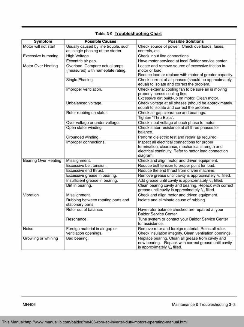
Table 3-9 Troubleshooting Chart
Symptom Possible Causes Possible SolutionsMotor will not start Usually caused by line trouble, such
as, single phasing at the starter.Check source of power. Check overloads, fuses,controls, etc.
Excessive humming High Voltage. Check input line connections.Eccentric air gap. Have motor serviced at local Baldor service center.
Motor Over Heating Overload. Compare actual amps(measured) with nameplate rating.
Locate and remove source of excessive friction inmotor or load.Reduce load or replace with motor of greater capacity.
Single Phasing. Check current at all phases (should be approximatelyequal) to isolate and correct the problem.
Improper ventilation. Check external cooling fan to be sure air is movingproperly across cooling fins.Excessive dirt build-up on motor. Clean motor.
Unbalanced voltage. Check voltage at all phases (should be approximatelyequal) to isolate and correct the problem.
Rotor rubbing on stator. Check air gap clearance and bearings.Tighten “Thru Bolts”.
Over voltage or under voltage. Check input voltage at each phase to motor.Open stator winding. Check stator resistance at all three phases for
balance.Grounded winding. Perform dielectric test and repair as required.Improper connections. Inspect all electrical connections for proper
termination, clearance, mechanical strength andelectrical continuity. Refer to motor lead connectiondiagram.
Bearing Over Heating Misalignment. Check and align motor and driven equipment.Excessive belt tension. Reduce belt tension to proper point for load.Excessive end thrust. Reduce the end thrust from driven machine.Excessive grease in bearing. Remove grease until cavity is approximately 3/4 filled.Insufficient grease in bearing. Add grease until cavity is approximately 3/4 filled.Dirt in bearing. Clean bearing cavity and bearing. Repack with correct
grease until cavity is approximately 3/4 filled.Vibration Misalignment. Check and align motor and driven equipment.
Rubbing between rotating parts andstationary parts.
Isolate and eliminate cause of rubbing.
Rotor out of balance. Have rotor balance checked are repaired at yourBaldor Service Center.
Resonance. Tune system or contact your Baldor Service Centerfor assistance.
Noise Foreign material in air gap orventilation openings.
Remove rotor and foreign material. Reinstall rotor.Check insulation integrity. Clean ventilation openings.
Growling or whining Bad bearing. Replace bearing. Clean all grease from cavity andnew bearing. Repack with correct grease until cavityis approximately 3/4 filled.
This Manual:http://www.manuallib.com/baldor/mn406-rpm-ac-inverter-duty-motors-operating-manual.html

3−4 Maintenance & Troubleshooting MN406
Suggested bearing and winding RTD setting guidelines for Non−Hazardous Locations ONLYMost large frame AC Baldor�Reliance motors with a 1.15 service factor are designed to operate below aClass B (80°C) temperature rise at rated load and are built with a Class H winding insulation system.Based on this low temperature rise, RTD (Resistance Temperature Detectors) settings for Class B riseshould be used as a starting point. Some motors with 1.0 service factor have Class F temperature rise.The following tables show the suggested alarm and trip settings for RTDs. Proper bearing and windingRTD alarm and trip settings should be selected based on these tables unless otherwise specified forspecific applications.If the driven load is found to operate well below the initial temperature settings under normal conditions,the alarm and trip settings may be reduced so that an abnormal machine load will be identified.The temperature limits are based on the installation of the winding RTDs imbedded in the winding asspecified by NEMA. Bearing RTDs should be installed so they are in contact with the outer race on ballor roller bearings or in direct contact with the sleeve bearing shell.
Winding RTDs − Temperature Limit In �C (40�C Maximum Ambient)
Motor LoadClass B Temp Rise � 80°C
(Typical Design) Class F Temp Rise � 105°C Class H Temp Rise � 125°C
Alarm Trip Alarm Trip Alarm Trip� Rated Load 130 140 155 165 175 185Rated Load to 1.15 S.F.
140 150 160 165 180 185
Note: � Winding RTDs are factory production installed, not from Mod−Express.� When Class H temperatures are used, consider bearing temperatures and relubrication requirements.
Bearing RTDs − Temperature Limit In �C (40�C Maximum Ambient)
Bearing TypeGrease
Anti−FrictionAlarm Trip
Standard 100 110
Axial FloatRPM AC motors have a wave spring washer between the drive end bracket and bearing. The oppositedrive end bearing is positioned axially by a float restricting inner cap. Axial float (including bearinginternal clearance) should be within the following limits:
Axial Float −In./Min.
Maximum MinimumFrame Size In. mm. In. mm.
FL180 thru L440(FDL112 thru DL280)
.051 1.29 .013 .33
The L440 (DL280) frame wavy spring is located on the opposite drive end.
This Manual:http://www.manuallib.com/baldor/mn406-rpm-ac-inverter-duty-motors-operating-manual.html

Baldor District Offices
This Manual:http://www.manuallib.com/baldor/mn406-rpm-ac-inverter-duty-motors-operating-manual.html

2008 Baldor Electric CompanyMN406
All rights reserved. Printed in USA3/09
BALDOR ELECTRIC COMPANYP.O. Box 2400 Fort Smith, AR 72901−2400
(479) 646−4711 Fax (479) 648−5792www.baldor.com
A MEMBER OF THE ABB GROUP
This Manual:http://www.manuallib.com/baldor/mn406-rpm-ac-inverter-duty-motors-operating-manual.html