baja sae 2010 conceptual design review. statement of work baja sae is an international collegiate...
TRANSCRIPT

BAJA SAE 2010
Conceptual Design Review

Statement of Work Baja SAE is an international collegiate
design competition sponsored by the Society of Automotive Engineers. The program simulates real-world engineering design projects and the related challenges with the goal of developing and building a small off-road vehicle. Teams from around the world compete in static and dynamic events to have their design accepted for manufacture by a fictitious firm.
Team Responsibilities Sam Moran – Chief Executive Officer; Frame Designer;
Welder/Grinder Michael Guilfoy – Steering Engineer; Chief Financial
Officer; Welder/Machinist Sam Weitkemper – Drivetrain Engineer; Executive
Secretary Ben McNealy – Braking Engineer; Analyst; Director of
Internet Services Matt Wantland – Analyst; Materials Acquisition
Specialist; Fabricator Dan Pickering – Suspension Engineer; Chief Mechanic Ahmed Al-Gattan – Chief Safety Officer
Customers SAE Competition Fictitious Firm
Safe vehicle Maneuverability, Traction, Suspension,
Acceleration Design/Manufacturability Cost
Sponsors Competitive vehicle Promotion
Faculty Advisors Competition success Educational experience

Benchmarking Vehicle Engineering Specifications
Front Track Width
Rear Track Width
Wheelbase
Weight
Suspension
Drivetrain
Data from 2009 Baja SAE Alabama competition

Benchmarking
42 44 46 48 50 52 54 56 58 60 62 64 66 68 70 72 74 76 78 80 82 84 86
0
1
2
3
4
5
6
7
8
Number of Teams Using a Specific Wheelbase
Wheelbase (in.)
Nu
mb
er
of
Te
am
s
2010 TU car
2009 TU car

Benchmarking
48 49 50 51 52 53 54 55 56 57 58 59 60 61 62 63 64 650
2
4
6
8
10
12
14
16
Number of Teams Using a Specific Front Track Width
Front Track Width (in.)
Nu
mb
er
of
Te
am
s
2010 TU car
2009 TU car

Benchmarking
49 50 51 52 53 54 55 56 57 58 59 60 61 62 63 640
2
4
6
8
10
12
14
16
Number of Teams Using a Specific Rear Track Width
Rear Track Width (in.)
Nu
mb
er
of
Te
am
s 2010 TU car
2009 TU car
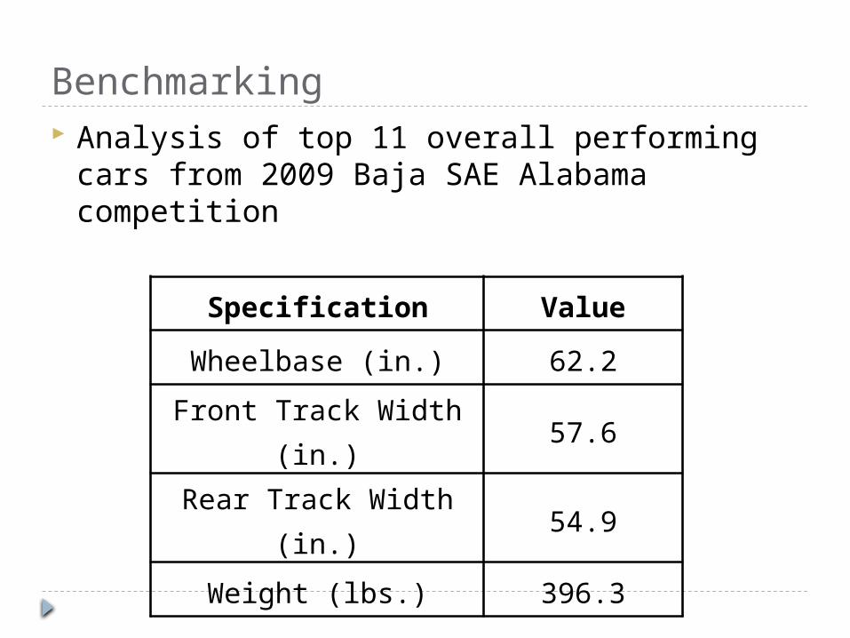
Benchmarking Analysis of top 11 overall performing cars
from 2009 Baja SAE Alabama competition
Specification Value
Wheelbase (in.) 62.2
Front Track Width (in.) 57.6
Rear Track Width (in.) 54.9
Weight (lbs.) 396.3
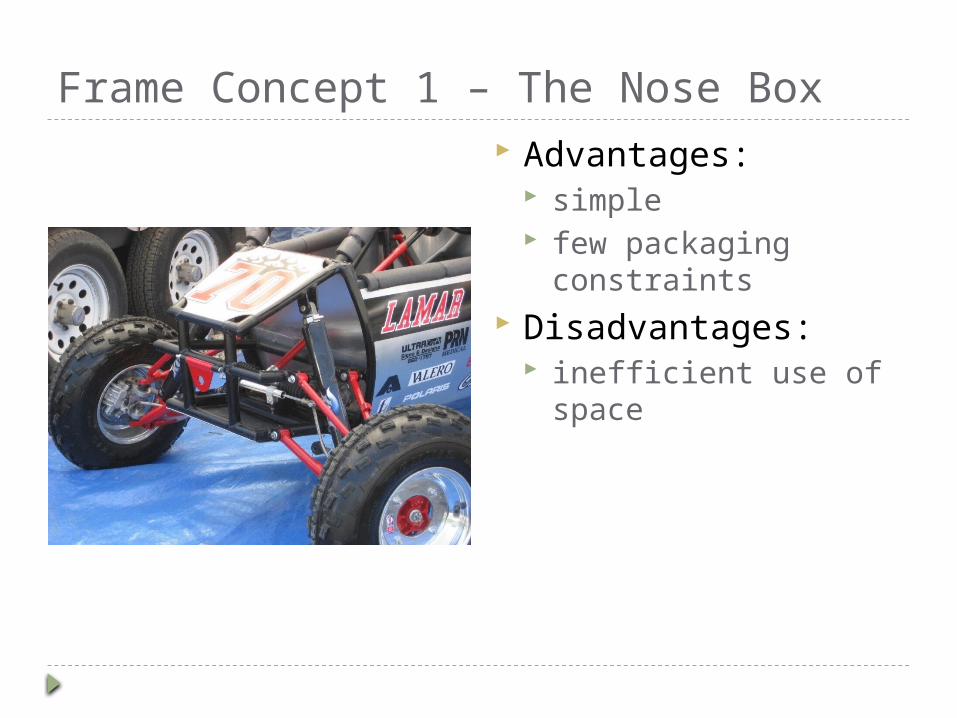
Frame Concept 1 – The Nose Box Advantages:
simple few packaging
constraints Disadvantages:
inefficient use of space

Frame Concept 2 – Integrated Cockpit Advantages:
more legroom efficient use of space light
Disadvantages: Complicated design

Frame Concept 3 – “The Cage” Advantages:
simple design requires the least
amount of planning allows for last-stage
drivetrain changes Disadvantages:
heavy difficult drivetrain
maintenance
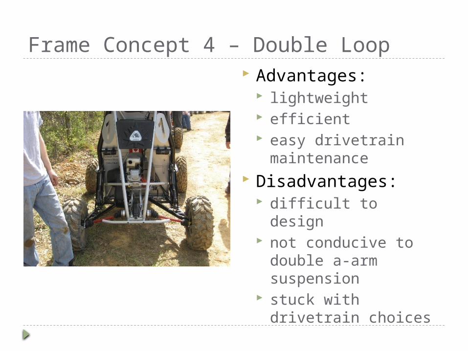
Frame Concept 4 – Double Loop Advantages:
lightweight efficient easy drivetrain
maintenance Disadvantages:
difficult to design not conducive to
double a-arm suspension
stuck with drivetrain choices
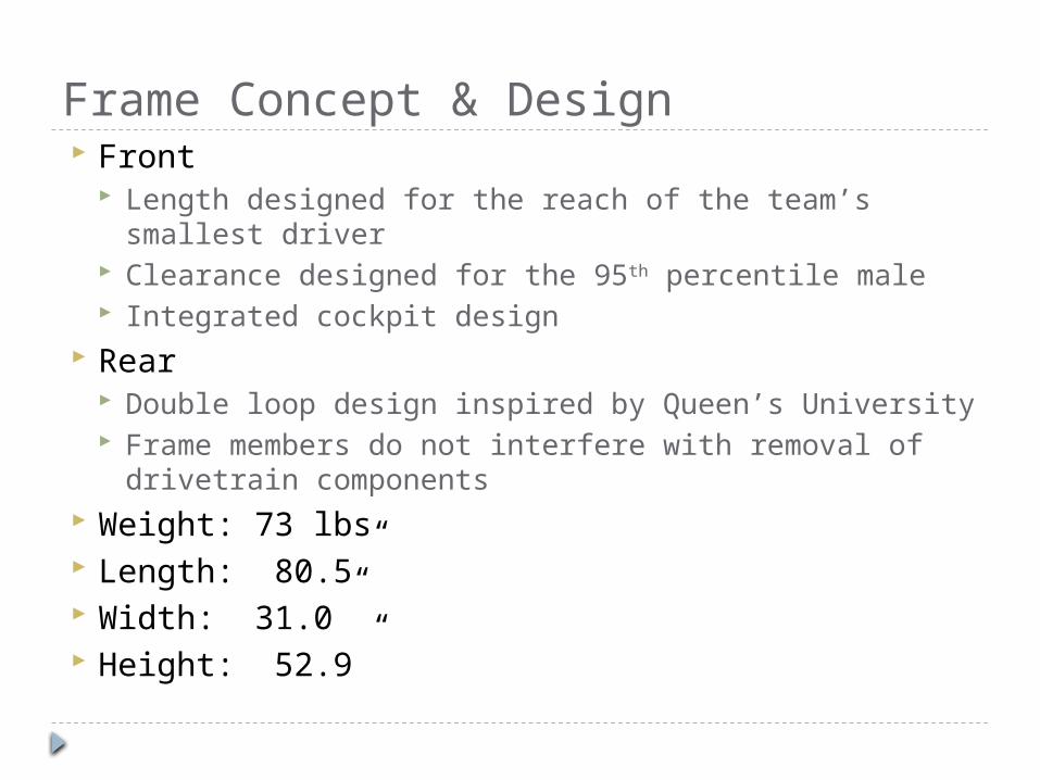
Frame Concept & Design Front
Length designed for the reach of the team’s smallest driver
Clearance designed for the 95th percentile male Integrated cockpit design
Rear Double loop design inspired by Queen’s University Frame members do not interfere with removal of
drivetrain components Weight: 73 lbs Length: 80.5” Width: 31.0” Height: 52.9”
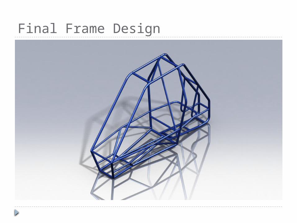
Final Frame Design

Frame Material Given in 1018 PCS 2 different
specifications -Strength/Stiffness Critical Components –
Roll Cage Non-Critical
Components – frontal/side impact
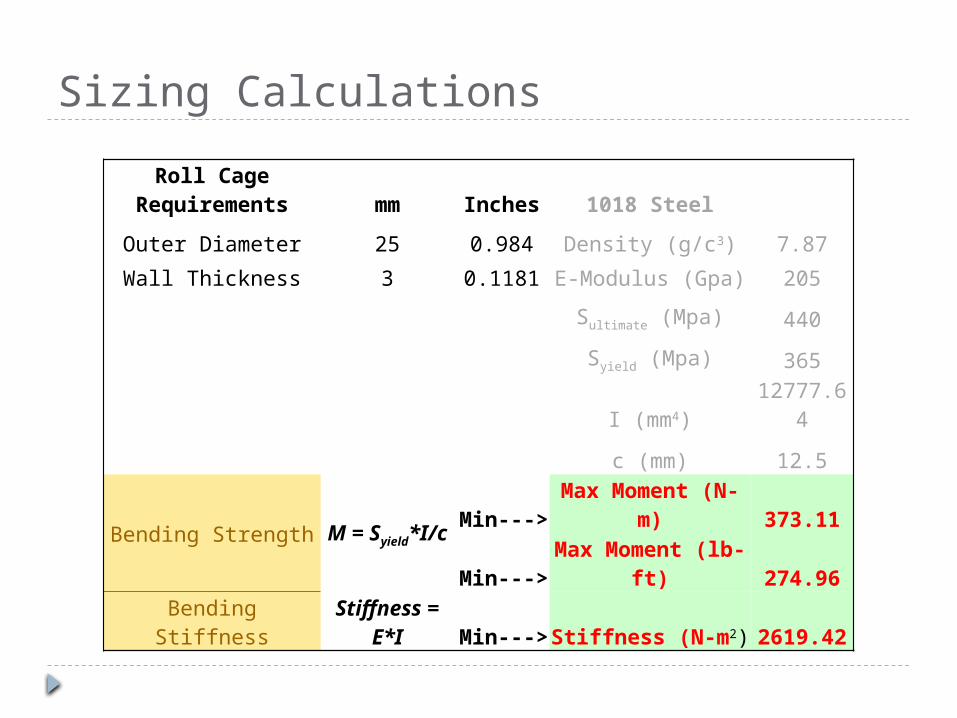
Sizing Calculations
Roll Cage Requirements mm Inches 1018 Steel
Outer Diameter 25 0.984 Density (g/c3) 7.87
Wall Thickness 3 0.1181 E-Modulus (Gpa) 205
Sultimate (Mpa) 440
Syield (Mpa) 365
I (mm4) 12777.64
c (mm) 12.5
Bending Strength M = Syield*I/c Min---> Max Moment (N-m) 373.11
Min---> Max Moment (lb-ft) 274.96
Bending Stiffness Stiffness = E*I Min---> Stiffness (N-m2) 2619.42

Tubing Possibilities
Hi Performance – Expensive/Light Economical – Cheap/Heavy Compromise – In between
Tubing Size (in) Source Yield (Mpa) Strength (N-m) Stiffness (N-m2) Weight (lbs/ft)Minimum X X 375 2620 X
0.75 X .080 Tenaris 480 225 817 0.571.00 X 0.095 Tenaris 620 627 2385 0.911.25 X 0.095 Tenaris 550 903 4937 1.171.28 X 0.071 QuikService 365 462.1 4218.7 0.911.00 X 0.060 QuikService 365 235 1676 0.6

Frame Specifications
Option Cost Frame Wt. (lbs)1 - Economical $0.00 922 - Hi-Performance $650.00* 44.23 - Compromise $40.00 63.8
Lengths of Different TubingLarge Req. Tubing (ft) 25Small Req. Tubing (ft) 68
Non Required (ft) 0
Final Tubing SizesLrg OD (in) 1.28Lrg t (in) 0.071Sm OD (in) 1Sm t (in) 0.06
*http://www.airpartsinc.com/products/4130-steel-tubing.htm
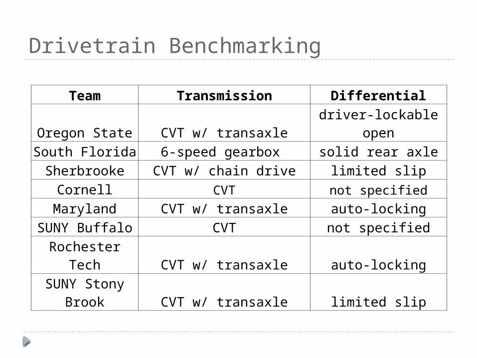
Drivetrain Benchmarking
Team Transmission DifferentialOregon State CVT w/ transaxle driver-lockable openSouth Florida 6-speed gearbox solid rear axleSherbrooke CVT w/ chain drive limited slip
Cornell CVT not specified
Maryland CVT w/ transaxle auto-lockingSUNY Buffalo CVT not specifiedRochester Tech CVT w/ transaxle auto-lockingSUNY Stony
Brook CVT w/ transaxle limited slip
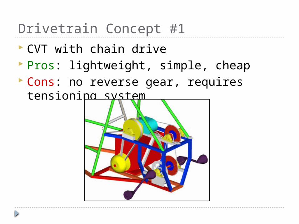
Drivetrain Concept #1 CVT with chain drive Pros: lightweight, simple, cheap Cons: no reverse gear, requires tensioning
system

Drivetrain Concept #2 Motorcycle gearbox
with chain drive Pros: easy to find,
includes reverse gear Cons: more difficult
for the driver

Drivetrain Concept Chosen CVTech CVT with Dana H-12 transaxle Pros: Simple, proven reliability, F/N/R, auto-
locking differential Cons: Heavy

Drivetrain Layout
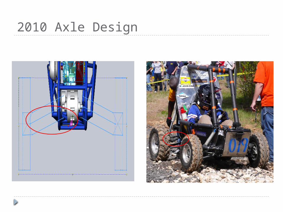
2010 Axle Design

Drivetrain SpecificationsMax Ratio 39.75 (35.60)Min Ratio 5.70 (6.98)Top Speed 34 mph (35 mph)Max Gradient 52 % (70%)Max Engine Power 9.1 HPMax Engine Torque 13.8 ft-lbsIdle 1750Max RPM 3800Weight 120 lbsTire Diameter 22”
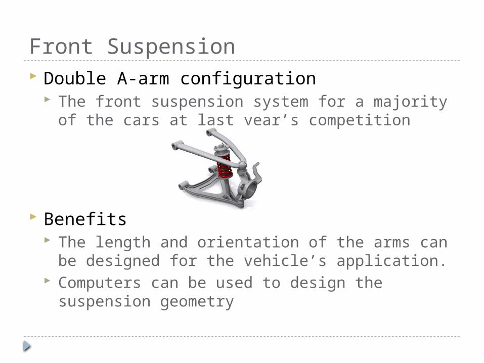
Front Suspension Double A-arm configuration
The front suspension system for a majority of the cars at last year’s competition
Benefits The length and orientation of the arms can be
designed for the vehicle’s application. Computers can be used to design the suspension
geometry

Front Suspension The vehicle was designed around the
suspension mounting points To prevent conflicts between the suspension and
other vehicle components Mechanism synthesis was performed in SolidWorks
with the help of Dr. Daily

Front Suspension Mounting points
Geometric constraint analysis was performed to determine the suspension mounting points for a given tie rod length and designed for no bump steer
Constraints: 5 degrees of camber and 10 inches of vertical travel for a 52-inch front track width
Top arm length: 16.375” Bottom arm length: 16.50”
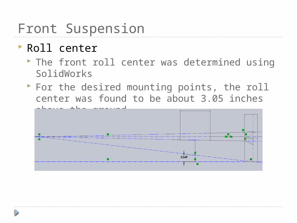
Front Suspension Roll center
The front roll center was determined using SolidWorks
For the desired mounting points, the roll center was found to be about 3.05 inches above the ground

Rear Suspension Solid Rear Axle/ Swing Arm
Top finishers such as Queen’s University and Michigan University used a swing arm with a solid rear axle.
Double A-arm A majority of the cars at last year’s Mini Baja used
a double wishbone configuration. More appropriate for cars without a solid rear axle Simple After discussing options with the team, a double
wishbone configuration was chosen

Rear Suspension Mounting points
Geometric constraint analysis was again performed to determine the suspension mounting points
Constraints: no camber change and 8 inches of vertical travel for a 50-inch rear track width
Top arm length: 16.50” Bottom arm length: 16.50”
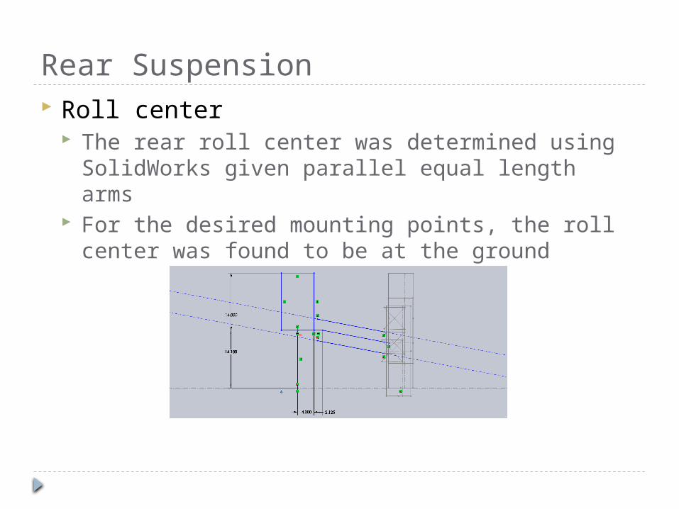
Rear Suspension Roll center
The rear roll center was determined using SolidWorks given parallel equal length arms
For the desired mounting points, the roll center was found to be at the ground
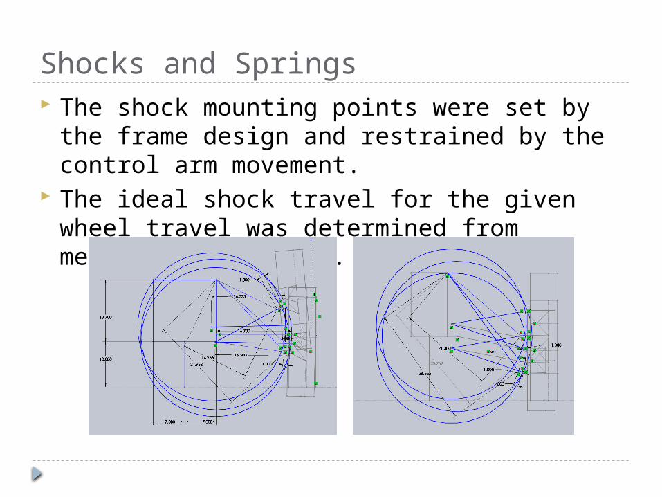
Shocks and Springs The shock mounting points were set by the
frame design and restrained by the control arm movement.
The ideal shock travel for the given wheel travel was determined from mechanism synthesis.

Steering Concepts Power Steering
Additional components
Requires power
Complicated integrationinside steering box
Four-Wheel Steering Challenging integration
Untested in competitionconditions
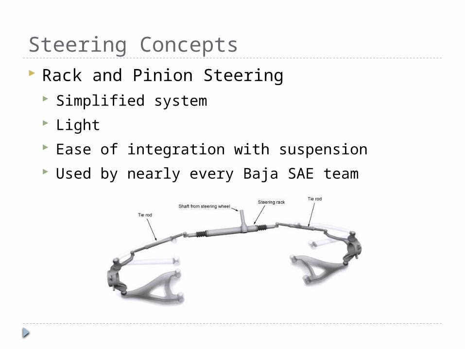
Steering Concepts Rack and Pinion Steering
Simplified system Light Ease of integration with suspension Used by nearly every Baja SAE team

Ackerman Geometry
62.5”
51”

Modeling Steering Angles
Outside Wheel Lock Position Inside Wheel Lock Position
27.73° 45.4
9°
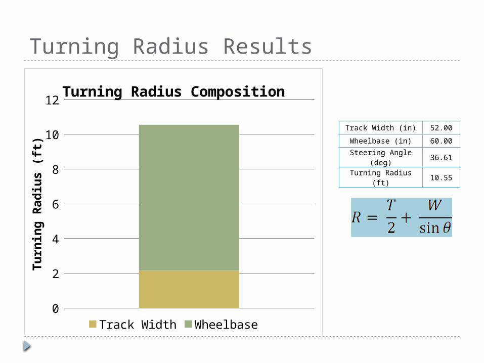
Turning Radius Results
Track Width (in) 52.00
Wheelbase (in) 60.00
Steering Angle (deg) 36.61
Turning Radius (ft) 10.55
0
2
4
6
8
10
12Turning Radius Composition
Track Width Wheelbase
Tu
rnin
g R
ad
ius (
ft)

Steering Specifications Chosen Concept: Rack and Pinion
14 inch length; 4.5 inches of travel 1.5 turns lock-to-lock Turning radius of approximately 10.5 feet Ackerman Geometry Tie Rod Connection Rack mounting to minimize lateral loads Rack mounting considered in frame design Front Suspension design clearance issues
addressed
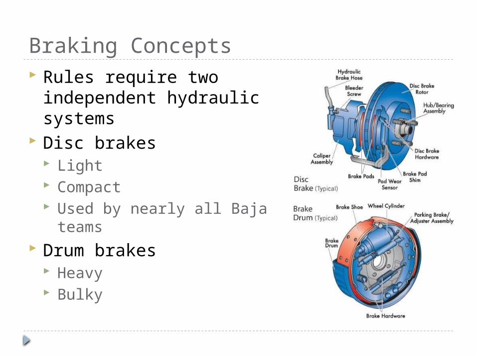
Braking Concepts Rules require two
independent hydraulic systems
Disc brakes Light Compact Used by nearly all Baja
teams Drum brakes
Heavy Bulky
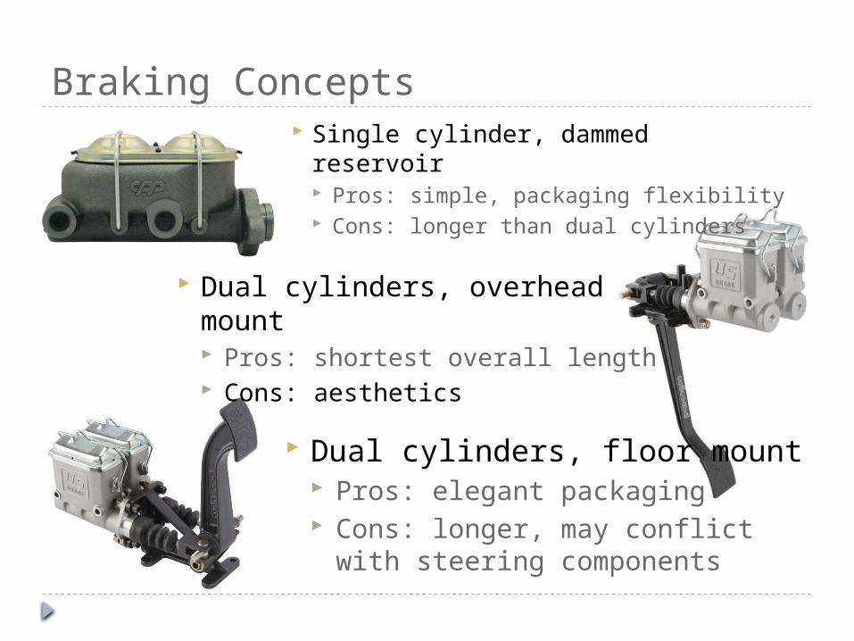
Braking Concepts Single cylinder, dammed reservoir
Pros: simple, packaging flexibility Cons: longer than dual cylinders
Dual cylinders, overhead mount Pros: shortest overall length Cons: aesthetics
Dual cylinders, floor mount Pros: elegant packaging Cons: longer, may conflict with
steering components

Braking Concepts Rigid lines
Pros: Rigid, look good Cons: Difficult to install
Braided flex lines Pros: Flexible, easier to install Cons: Heavier

Braking Concept Selected Polaris discs and calipers Dual US Brake master cylinders Wilwood reverse mount pedal Braided steel flex line

Safety Braking
Two independent hydraulic braking systems Capable of locking the wheels No plastic brake lines
Drivetrain CVT cover – made of polymer Gas catch – made of polymer
Kill Switches Two kill switches required One in cockpit, one in rear

Safety Frame pads
The minimum required thickness is ½”. The cost is $17.95 per 3 feet. Need 6 feet.
Safety helmet Motor cross style, Snell M2005 specification
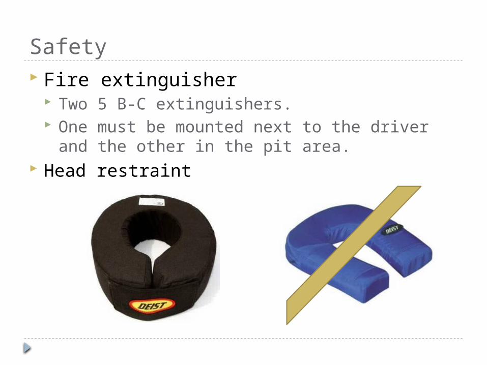
Safety Fire extinguisher
Two 5 B-C extinguishers. One must be mounted next to the driver and the
other in the pit area. Head restraint

Goals and Deadlines January 25 – complete design
stress analysis CAD models
February 28 – drivable vehicle rolls under its own power basic safety gear
March 28 – competition-ready vehicle meets all rules fully functional, painted, polished, done.
April 8-11 – 2010 Baja SAE Carolina competition

Schedule
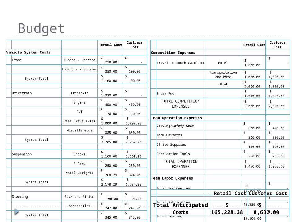
Budget Retail Cost
Customer Cost
Vehicle System Costs
Frame Tubing - Donated $ 750.00
$ -
Tubing - Purchased $ 350.00
$ 100.00
System Total $
1,100.00 $ 100.00
Drivetrain Transaxle $
1,320.00 $
-
Engine $ 450.00
$ 450.00
CVT $ 130.00
$ 130.00
Rear Drive Axles $
1,000.00 $
1,000.00
Miscellaneous $ 885.00
$ 680.00
System Total $
3,785.00 $
2,260.00
Suspension Shocks $
1,160.00 $
1,160.00
A-Arms $ 250.00
$ 250.00
Wheel Uprights $ 768.29
$ 374.00
System Total $
2,178.29 $
1,784.00
Steering Rack and Pinion $
98.00 $
98.00
Accessories $ 247.00
$ 247.00
System Total $ 345.00
$ 345.00
Braking $
1,124.09 $ 433.00
Tires and Maintenance $ 396.00
$ 160.00
Miscellaneous $ 500.00
$ 500.00
TOTAL VEHICLE EXPENSES $ 9,428.38
$ 5,582.00
Retail Cost Customer
Cost
Competition Expenses
Travel to South Carolina Hotel $
1,000.00 $
-
Transportation and More
$ 1,000.00
$ 1,000.00
TOTAL $
2,000.00 $
1,000.00
Entry Fee $
1,000.00 $
1,000.00
TOTAL COMPETITION EXPENSES
$ 3,000.00
$ 2,000.00
Team Operation Expenses
Driving/Safety Gear $ 800.00
$ 400.00
Team Uniforms $ 300.00
$ 300.00
Office Supplies $ 100.00
$ 100.00
Fabrication Tools $ 250.00
$ 250.00
TOTAL OPERATION EXPENSES
$ 1,450.00
$ 1,050.00
Team Labor Expenses
Total Engineering $
97,500.00 $
-
Total Fabrication $
43,350.00 $
-
Total Testing $
10,500.00 $
-
TOTAL LABOR EXPENSES $ 151,350.00
$ - Retail Cost Customer Cost
Total Anticipated Costs
$ 165,228.38
$ 8,632.00

Budget Retail Cost Customer Cost
Competition Expenses $ 3,000.00 $ 2,000.00
Vehicle System Costs
Frame $ 1,100.00 $ 100.00
Drivetrain $ 3,785.00 $ 2,260.00
Suspension $ 2,178.29 $ 1,784.00
Steering $ 345.00 $ 345.00
Braking $ 1,124.09 $ 433.00
Tires and Maintenance $ 396.00 $ 160.00
Miscellaneous $ 500.00 $ 500.00
TOTAL VEHICLE EXPENSES $ 9,428.38 $ 5,582.00
Team Operation Expenses $ 1,450.00 $ 1,050.00
Team Labor Expenses $ 151,350.00 $ -
Total Anticipated Costs $
165,228.38 $ 8,632.00

Budget
Hourly Rate Extended Cost
Item DescriptionRetail Rate
Customer Rate
Quantity
Retail Cost
Customer Cost
Engineering Design & Analysis $75.00 $0.00 1300 $97,500.00 $0.00
Fabrication Machining Time $50.00 $0.00 30 $1,500.00 $0.00
Welding Fixtures $45.00 $0.00 12 $540.00 $0.00
Tube Bending $45.00 $0.00 6 $270.00 $0.00
Welding $45.00 $0.00 72 $3,240.00 $0.00
Assembly $45.00 $0.00 840 $37,800.00 $0.00
Testing Testing & Analysis $75.00 $0.00 140 $10,500.00 $0.00
Total Labor Costs 2400$151,350.
00 $0.00