bad boy spot luminaire - prg/media/files/us/prg-products/... · prg part number: 02.9812.0005 e ......
TRANSCRIPT

SOFTWARE VERSION 1.6
WWW.PRG.COM
BAD BOY® SPOT LUMINAIRE
FIELD SERVICE MANUAL

AutoPar®, Bad Boy®, PRG Series 400®, Mbox Extreme®, OHM™, V476™, V676™, Virtuoso®, Virtuoso® DX, Virtuoso® DX2,
and VL6C+™ are trademarks of Production Resource Group, LLC, registered in the U.S. and other countries.
All other brand names which may be mentioned in this manual are trademarks or registered trademarks of their respective companies.
This manual is for informational use only and is subject to change without notice. Please check www.prg.com for the latest version.
PRG assumes no responsibility or liability for any claims resulting from errors or inaccuracies that may appear in this manual.
Bad Boy® Spot Luminaire Field Service Manual
Version as of: June 23, 2011
PRG part number: 02.9812.0005 E
Production Resource Group
Dallas Office
8617 Ambassador Row, Suite 120
Dallas, Texas 75247
www.prg.com
Bad Boy® Spot Luminaire Field Service Manual
©2009-2011 Production Resource Group, LLC. All Rights Reserved.

FOREWORD
Compliance Notice
This device complies with Part 15 of the FCC rules. Operation is subject to the following two conditions: 1) This device
may not cause harmful interference, and 2) This device must accept any interference received, including interference
that may cause undesired operation.
Conforms to:
UL STD 1573
Certified to:
CAN/CSA STD E598-1
CAN/CSA STD E598-2-17
Safety Notice
It is extremely important to read ALL safety information and instructions provided in this manual and any
accompanying documentation before installing and operating the products described herein. Heed all cautions and
warnings during installation and use of this product.
Safety symbols used throughout this manual are as follows:
GENERAL INFORMATION PERTAINING TO PROTECTION AGAINST ELECTRICAL SHOCK, FIRE, EXPOSURE TO
EXCESSIVE UV RADIATION, AND INJURY TO PERSONS CAN BE FOUND BELOW.
WARNING: INSTRUCTIONS FOR CONTINUED PROTECTION AGAINST FIRE
1) PRG luminaires have been designed for use only with specific lamps. Note lamp type before replacing. Installing
another type of lamp may be hazardous.
2) PRG luminaires may be mounted on any type of surface as long as mounting instructions are followed. See
instructions detailed in this manual.
3) Replace fuses with same type and rating only.
4) Minimum distance from head to any flammable object is 2m.
WARNING: INSTRUCTIONS FOR CONTINUED PROTECTION AGAINST ELECTRICAL SHOCK
1) PRG luminaires are designed for dry locations only. Exposure to rain or moisture may damage luminaire.
2) Disconnect power before servicing any PRG equipment.
3) Servicing to be performed by qualified personnel only.
WARNING: INSTRUCTIONS FOR CONTINUED PROTECTION AGAINST EXPOSURE TO EXCESSIVE ULTRAVIOLET RADIATION
1) PRG luminaires may use an HID type lamp which produces UV radiation. DO NOT look directly at lamp.
2) It is hazardous to operate luminaires without complete lamp enclosure in place or when lens is damaged.
Lenses or UV shields shall be changed if they have become visibly damaged to such an extent that their
effectiveness is impaired.
CAUTION advising of potential damage to product.
WARNING advising of potential injury or death to persons.
BAD BOY® SPOT LUMINAIRE FIELD SERVICE MANUAL I

WARNING: INSTRUCTIONS FOR PROTECTION AGAINST INJURY TO PERSONS
1) Exterior surfaces of the luminaire will be hot during operation. Use appropriate safety equipment (gloves, eye
protection, etc.) when handling and adjusting hot equipment and components. Service and maintenance should
be performed only by qualified personnel as determined by the high pressure lighting fixture manufacturer.
2) Arc lamps generate intense heat. Disconnect power and allow lamp to cool for 5 minutes before relamping.
3) Arc lamps emit ultraviolet radiation which can cause serious skin burn and eye inflammation. Additionally, arc
lamps operate under high pressure at very high temperatures. Should the lamp break, there can exist a danger
of personal injury and/or fire from broken lamp particles being discharged.
4) The lamp shall be changed if it has become damaged or thermally deformed.
5) If lamp is touched with bare hands, clean lamp with denatured alcohol and wipe with lint-free cloth before
installing or powering up the luminaire.
6) Serious injury may result from the generation of ozone by this lamp system. A proper means of venting must be
provided.
II BAD BOY® SPOT LUMINAIRE FIELD SERVICE MANUAL

Notes de sécurité
Avant de procéder à l’installation des produits décrits dans ce guide et de les mettre en marche, il est extrêmement
important de lire TOUS les renseignements et TOUTES les directives de sécurité contenues dans ce guide ainsi que
toute documentation jointe. Tenir compte de tous les avertissements et suivre toutes les précautions pendant
l’installation et l’utilisation de cet appareil.
Les symboles de sécurité utilisés dans ce guide sont les suivants :
CETTE SECTION CONTIENT DES INFORMATIONS GÉNÉRALES POUR SE PROTÉGER CONTRE LES DÉCHARGES
ÉLECTRIQUES, LES INCENDIES, L’EXPOSITION EXCESSIVE AUX RAYONS UV ET TOUT AUTRE ACCIDENT
POUVANT ENTRAÎNER DES BLESSURES.
AVERTISSEMENT: RISQUE D’ EXPLOSION.
1) Le service et le maintenance ne devront être assurés que par des personnes qualifiées comme precisé par le
frabricant des lampes à haute pression.
2) Des vêtement de protection et les procédures précisées dans le manuel du frabricant doit être fournies.
AVERTISSEMENT: RÉGLAGE DES LAMPES
1) Chaleur intense. Débrancher le matériel et laisser refroidir pendant 5 minutes avant de rallumer.
2) Risque l’incendie. N’utilise que des Philips MSR Gold™ FastFit Lamp.
AVERTISSEMENT: DIRECTIVES POUR SE PROTÉGER CONTRE UNE EXPOSITION EXCESSIVE AUX RAYONS UV
1) Risque d’explosion en cas de radiation ultraviolet imprantes.
2) Ne pas intervener en l’absence de confinement de la lampe en place ou quand la lentille est abîmée.
AVERTISSEMENT: DIRECTIVES POUR SE PROTÉGER CONTRE LES ACCIDENTS POUVANT ENTRAÎNER DES BLESSURES
1) Chaleur intense. Eviter tout contact avec des personnes ou des tissues. Attention, de graves blessures
peuvent résulter de production d’ozone par cette lampe. Un système de ventilation adapté doit être fournies
2) La température de surface = 300.c
La temperature de l’ambiance = 50.c
3) Ne convient pas pour un usage résidential.
4) Utilisable seulement dans les locaux secs.
ATTENTION Ce symbole annonce que l’appareil risque d’être endommagé.
AVERTISSEMENT Ce symbole annonce qu’il y a risque d’accident grave ou même fatal.
BAD BOY® SPOT LUMINAIRE FIELD SERVICE MANUAL III

Revision History
This manual has been revised as follows:
Version Release Date Notes
BASIC September 22, 2009 Initial release.
A March 3, 2010 Added CMY luminaire information where applicable.
B May 4, 2010Updated Wiring Diagram. Added new Hi-Temp Pinch Fan and
Ignitor replacement procedures.
C1 July 16, 2010
Added Front Lens and Retaining Ring info to Maintenance and
IPB sections. Added Designer Color and Gobo Wheel stan-
dard configurations to Description section.
C2 November 10, 2010 Updated book format. (No change to technical information.)
D January 5, 2011Corrected configuration of the Designer Color Wheel standard
positions in Description section.
E June 23, 2011Added part number for Sonic Belt Tension Meter on Pan and
Tilt Drive maintenance procedures.
IV BAD BOY® SPOT LUMINAIRE FIELD SERVICE MANUAL

TABLE OF CONTENTS
Introduction
About This Manual........................................................................................................................................................................ 1
Additional Documentation ............................................................................................................................................................ 1
Customer Service ......................................................................................................................................................................... 2
Chapter 1. Description
Features
Overview....................................................................................................................................................................................... 4
Features ................................................................................................................................................................................ 4
Luminaire Models .................................................................................................................................................................. 5
Components
Exterior Components.................................................................................................................................................................... 6
Head and Enclosure Components ............................................................................................................................................... 7
Yoke Components ........................................................................................................................................................................ 8
Designer Color and Gobo Wheel Configurations ....................................................................................................................... 10
Chapter 2. Testing & Troubleshooting
Testing
Test Screen................................................................................................................................................................................. 14
Mechanical Tests ........................................................................................................................................................................ 15
Group Test .................................................................................................................................................................................. 16
Troubleshooting
Errors .......................................................................................................................................................................................... 17
Basic Troubleshooting ................................................................................................................................................................ 19
Component Troubleshooting ...................................................................................................................................................... 20
Lamp Issues ........................................................................................................................................................................ 20
Wheel Stack and/or Frost (Diffusion) Issues ....................................................................................................................... 21
Fan/Cooling Issues.............................................................................................................................................................. 22
Lens Issues ......................................................................................................................................................................... 23
Menu Display Issues ........................................................................................................................................................... 24
Pan/Tilt Issues ..................................................................................................................................................................... 25
Chapter 3. Maintenance
Equipment Handling
Proper Lamp Servicing and Operation ....................................................................................................................................... 28
Wheel Stack Road Case Instructions......................................................................................................................................... 29
Routine Maintenance
Removing the Head Covers ....................................................................................................................................................... 30
Removing the Aft Cover ............................................................................................................................................................. 31
Removing the Enclosure Covers ................................................................................................................................................ 32
Cleaning the Head Electrostatic Filters ...................................................................................................................................... 33
Cleaning the Enclosure Intake Filters ......................................................................................................................................... 34
Cleaning the Luminaire Exterior ................................................................................................................................................. 35
Cleaning the Lenses ................................................................................................................................................................... 36
Cleaning Gobo, Color and Dimmer Wheels ............................................................................................................................... 39
Cleaning the Reflector ................................................................................................................................................................ 40
Cleaning the UV/IR Window ....................................................................................................................................................... 41
Remove and Replace Procedures
Replacing the Lamp ................................................................................................................................................................... 42
Adjusting the Lamp .................................................................................................................................................................... 44
Replacing a Gobo....................................................................................................................................................................... 45
Replacing a Designer Color Filter............................................................................................................................................... 48
Replacing the Front Glass .......................................................................................................................................................... 50
BAD BOY® SPOT LUMINAIRE FIELD SERVICE MANUAL V

Replacing the Wheel Stack......................................................................................................................................................... 51
Replacing the Frost/Diffuser Paddle........................................................................................................................................... 55
Replacing the Diffuser Sensor PCB............................................................................................................................................ 57
Replacing the Zoom Controller PCB .......................................................................................................................................... 58
Replacing a Zoom Sensor PCB.................................................................................................................................................. 59
Replacing the Main Head Fan .................................................................................................................................................... 62
Replacing the Tip Pinch Fan (Original Version)........................................................................................................................... 64
Replacing the Tip Pinch Fan (Hi-Temp Version) ......................................................................................................................... 65
Replacing the UV/IR Window Assembly..................................................................................................................................... 66
Replacing the Reflector .............................................................................................................................................................. 67
Replacing a 2A Fuse................................................................................................................................................................... 68
Replacing the 3A Fuse................................................................................................................................................................ 69
Replacing the EMI Ballast Enclosure.......................................................................................................................................... 70
Replacing the Interface/LVS Module .......................................................................................................................................... 72
Replacing the Ignitor PCB .......................................................................................................................................................... 74
Replacing the Pan/Tilt Controller PCB ....................................................................................................................................... 76
Replacing the Pan/Tilt COT Sensor PCB ................................................................................................................................... 77
Replacing the Pan Drive Assembly............................................................................................................................................. 79
Replacing the Tilt Drive Assembly .............................................................................................................................................. 82
Setting Pan/Tilt Belt Tension....................................................................................................................................................... 83
Chapter 4. Illustrated Parts Breakdown
Overview
About this IPB............................................................................................................................................................................. 86
Parts Breakdown
Covers and Included Items......................................................................................................................................................... 87
Bad Boy Spares Kit .................................................................................................................................................................... 89
Appendix A. Technical Specifications
Bad Boy Spot Luminaire............................................................................................................................................................. 96
Bad Boy Road Case ................................................................................................................................................................... 98
AC Line Current / Power vs. Voltage .......................................................................................................................................... 99
Photometric Data...................................................................................................................................................................... 100
Narrow Zoom..................................................................................................................................................................... 101
Medium Zoom ................................................................................................................................................................... 102
Wide Zoom ........................................................................................................................................................................ 103
Logarithmic Beam Illuminance Comparison ..................................................................................................................... 104
Appendix B. Wiring Diagrams
Bad Boy Luminaire Wiring Diagram.......................................................................................................................................... 105
VI BAD BOY® SPOT LUMINAIRE FIELD SERVICE MANUAL

INTRODUCTION
About This Manual
This manual provides testing, troubleshooting, maintenance procedures, and illustrated parts breakdowns for the
following equipment:
+ Bad Boy® Spot Luminaire (20.9812.0001)
+ Bad Boy™ CMY Spot Luminaire (20.9812.0002)
This manual is intended for use in field servicing and is not a comprehensive shop-level manual.
WARNING: It is important to read ALL accompanying safety instructions to avoid damage to the product
and potential injury to yourself or others.
Additional Documentation
For installation and operation instructions, refer to the following PRG manual:
+ Bad Boy® Spot Luminaire User Manual (02.9812.0001.xx)
Technical updates regarding this equipment are issued by the PRG Dallas office. These updates are in the form of
Technical Bulletins, which contain procedures for equipment upgrades, retrofits, and repairs not found in the existing
manual(s).
For more information regarding DMX512 systems, refer to the DMX512/1990 & AMX 192 Standards publication
available from United States Institute for Theatre Technology, Inc. (USITT).
USITT
6443 Ridings Road
Syracuse, NY 13206-1111 USA
1-800-93USITT
www.usitt.org
For more information regarding Art-Net protocol, refer to the specification for Art-Net II Ethernet Communication
Standard available from Artistic Licence Ltd.
Artistic Licence (UK) Ltd (Registered Office)
24 Forward Drive, Christchurch Avenue,
Harrow, Middlesex, HA3 8NT, United Kingdom
+44 (0)20 88 63 45 15 (phone)
+44 (0)20 84 26 05 51 (fax)
www.artisticlicence.com
BAD BOY® SPOT LUMINAIRE FIELD SERVICE MANUAL 1

Customer Service
For technical assistance, contact the PRG International Service Center or contact your nearest PRG office. Contact
information for all PRG office locations can be found on our website at: www.prg.com/about-us/locations/
PRG Dallas (International Service)
8617 Ambassador Row, Suite 120
Dallas, Texas 75247 USA
Phone: 214.630.1963
Fax: 214.630.5867
Service Fax: 214.638.2125
Service Email: [email protected]
For additional resources and documentation, please visit our website at: www.prg.com
2 BAD BOY® SPOT LUMINAIRE FIELD SERVICE MANUAL

1.
DESCRIPTIONThis chapter contains an overview of luminaire features and components.
+ FEATURES
+ COMPONENTS

FEATURES
Overview
The Bad Boy Spot Luminaire from PRG Lighting combines the qualities of a
traditional automated light with a large venue fixture.
Features
+ Philips MSR Gold™ FastFit lamp that can be set to levels 900W, 1200W, or
1400W.
+ Built-in LCD touchscreen display which provides access to control,
configuration, status, and testing functions.
+ Zoom lens system consisting of four groups of lenses - each independently
controlled for accuracy while maintaining focus during zoom changes.
+ Zoom range of 8:1 from a narrow spot of 7° to a wide flood of 56°.
+ Edge control for gobo focus and gobo morphing.
+ Mechanical iris which provides continuous beam size control for both rapid
changes and smooth timed beam angle changes.
+ 8-inch diameter front lens which produces a large, full beam that easily can be
varied by the luminaire’s zoom lens and beam size iris.
+ Full-field dimming from 0 to 100% with accurate slow-speed control as well as fast bumps.
+ Standard Version - Quantum Color® system featuring four (4) color wheels with seven discrete colors on each
wheel: one (1) designer wheel with user-changeable color filters and three (3) fixed color wheels organized into
Cyan, Magenta, and Yellow (CYM).
+ CMY Version - CMY color system featuring three (3) cross-fading color wheels (Cyan, Magenta, and Yellow), plus
one (1) designer wheel with user-changeable color filters.
+ Instantaneous color bumps and flashes as well as smooth control for timed color changes.
+ Two (2) indexable, rotating gobo wheels with seven (7) gobos per wheel. Gobos are individually calibrated so the
unit will automatically index the orientation of each gobo regardless of placement.
+ Variable frost for smooth diffusion.
+ Servo-powered, lightning fast strobe mechanism.
+ Precision glass reflector with dichroic cold mirror coating.
+ On-board battery to address and configure fixture without main power.
+ Three-phase, high-speed servo motors for pan and tilt to provide repeatable, precise responses.
+ Pan and tilt locking mechanisms which automatically unlock when power is applied to the fixture.
+ Pan range of 540° and a tilt range of 270°.
+ Can be mounted and operated in any orientation.
+ Compatible with all PRG consoles and a wide variety of DMX512 and Art-Net consoles. An internal Ethernet
switch allows for daisy-chaining fixtures.
4 BAD BOY® SPOT LUMINAIRE FIELD SERVICE MANUAL

Luminaire Models
The Bad Boy Spot Luminaire is available in two versions:
+ Standard (20.9812.0001) - contains a Quantum Color® system.
+ CMY (20.9812.0002) - contains a CMY color system.
The Bad Boy CMY luminaire can be identified by a label on the input panel:
Figure 1-1: Identifying CMY Version
Depending on the Bad Boy luminaire model, the Wheel Stack Assembly will be different. The CMY Wheel Stack can
be identified by a label on the outer plate:
Figure 1-2: CMY Wheel Stack Label
YM
C OMM
C
200 -240 V A C
E T H ERNE TDMX
IN
T HR U
15 A M a x50 / 60 H z
IS POWERED
ACTIVEONLYWHEN FIXTURE
A C IN
C
M Y
C
M Y
BAD BOY® SPOT LUMINAIRE FIELD SERVICE MANUAL 5

COMPONENTS
Exterior Components
The following illustration shows the exterior Bad Boy components and controls.
Figure 1-3: Exterior Components
C OMM
200 - 240V AC
E T H ERNE TDMX
IN
T HR U
15 A M a x50 / 60 Hz
IS POWERED
ACTIVEONLYWHEN FIXTURE
A C IN
CONFIG
addr 043
univ A
1400w
ETHERNET
COMM
IN
DMX
THRU
15A Max
AC IN200 -240 VAC
50 / 60 Hz
LAMP
hrs 125
temp 34C
INFO
01:34
TEST
COMM
DMX
STATUS
OK
IS POWERED
ACTIVE ON LYWHEN FIXTURE
Neutrik® AC
DMX512 Input
DMX512 Thru
Upper Enclosure Detail
Upper Enclosure -Houses power supply, ballast, and provides Data In and Thru, and AC power connections. Also houses the Menu Touchscreen (see detail below).
Hanging Bracket Assembly (2) -Allows luminaire to be mounted on truss pipe.
Yoke Assembly -Houses Master Control Board (MCB) .
FRONT VIEW
Power Connector
Front Lens -8-inch diameter front lens.
Head Assembly -Houses Color, Gobo, Zoom, Iris, Frost, and Strobe mechanisms.
Ethernet Thru
Ethernet Input
Menu Touchscreen -Used to configure luminaire address and other options. Also, provides status information and testing.
Comm LED
Battery Wake Switch *
* Not available on all units
6 BAD BOY® SPOT LUMINAIRE FIELD SERVICE MANUAL

Head and Enclosure Components
The following illustration shows the major sub-assemblies located in the Bad Boy Head and Enclosure.
Figure 1-4: Head and Enclosure Components
Wheel Stack
LVS/Interface Module
EMI Ballast
Zoom Controller PCBAssembly
Enclosure
Front Lens
Aft Assembly(contains lamp, fans, reflector)
Lens Groups
BAD BOY® SPOT LUMINAIRE FIELD SERVICE MANUAL 7

Yoke Components
Tilt-Side Yoke
The following illustration shows the major sub-assemblies located in the Bad Boy Tilt-Side Yoke Leg.
Figure 1-6: Tilt-Side Yoke Leg
Ignitor PCB
Relay
Tilt Drive Assembly
Tilt-Side LegPan-Side Leg
R2 / Designer WheelHead Cover
Figure 1-5: Yoke Leg Identification
8 BAD BOY® SPOT LUMINAIRE FIELD SERVICE MANUAL

Pan-Side Yoke Leg
The following illustration shows the major sub-assemblies located in the Bad Boy Pan-Side Yoke Leg.
Figure 1-7: Pan-Side Yoke Leg
Pan/Tilt Controller PCB
BAD BOY® SPOT LUMINAIRE FIELD SERVICE MANUAL 9

Designer Color and Gobo Wheel Configurations
Designer Color Wheel Standard Configuration
The following drawing shows the standard Bad Boy Designer Color Wheel configuration.
Figure 1-8: Designer Color Wheel Standard Configuration
10 BAD BOY® SPOT LUMINAIRE FIELD SERVICE MANUAL

Standard Gobo Wheel Configuration
The following drawing shows the standard Bad Boy Designer Gobo Wheel configurations.
Figure 1-9: Gobo Wheel Standard Configurations
BAD BOY® SPOT LUMINAIRE FIELD SERVICE MANUAL 11

Notes
12 BAD BOY® SPOT LUMINAIRE FIELD SERVICE MANUAL

2.
TESTING & TROUBLESHOOTINGThis chapter provides testing and troubleshooting procedures for the luminaire.
+ TESTING
+ TROUBLESHOOTING

TESTING
Test Screen
The luminaire provides built-in test routines and recalibration
options which can be accessed through the Menu Touchscreen.
Actions may be applied to specific mechanisms, or in some
cases, to all mechanisms at once. At the Home screen, press the
Test panel to bring up the Test screen.
Options are as follows:
+ Re-Cal - press to bring up Recalibration Screen.
+ Re-Call ALL - press to bring up Re-Cal ALL Yes/No options.
+ Disable - press to bring up Disable Screen.
+ Mech Test - press to bring up Mech Test Screen. (See
"Mechanical Tests" on page 15 for more explanation of this
screen.)
+ Clean Lenses - press to position lenses so that all surfaces
may be cleaned with a cloth. (Note that pressing the button
does not actually clean the lenses.) Refer to "Cleaning the
Lenses" on page 36 for complete lens cleaning instructions.
+ Group Test - allows multiple Bad Boy luminaires to be run
through a configurable test sequence when chained together
via DMX512 or Ethernet. (See "Group Test" on page 16 for
more explanation of this screen.)
Press TEST tobring up Test screen
Test Sub-Menu Screens
14 BAD BOY® SPOT LUMINAIRE FIELD SERVICE MANUAL

Mechanical Tests
The Mechanical Test menu provides a method for exercising all luminaire mechanisms individually. Each mechanism
has a similar Test screen, Cyan is shown in the example below:
The following test functions are available:
+ Test Chase - The mechanism will move back and forth between two positions. The START/STOP button starts
and stops the motion, and the SPEED button sets the rate of the motion. For mechanisms with sensors, one of
the positions will be on the sensor and the other position will be off.
+ Manual Control - The slider on the right side of the screen moves the mechanism through its range of travel,
manually. Tapping the arrows will move the mechanism in half panel increments.
+ Feedback -The current status of the mechanisms encoder (POSITION) and sensor (SENSOR) are shown (if
available for that mechanism). STATUS indicates whether the mechanism is in an error state or normal operating
state.
+ Utility Functions - Press RE-CAL to recalibrate the mechanism or DISABLE to turn off the motor control to allow
the mechanism to move freely.
+ Configuration Information - HOME OFFSET indicates whether the home position* has been adjusted to fine
tune sensor positions (applies to gobo wheel only, see Control Channel table for zero wheel mechanism found in
the Bad Boy™ Spot Luminaire User Manual).
* Due to small variations in sensor and sensor board positions, the open position on a gobo wheel might not be precisely
aligned with the optical axis, creating a slight blockage on one side of the open beam. Adjust the wheel position via
DMX to get the proper alignment and send the HOME OFFSET command to store the current position as the new
"home" position. This position is stored in persistent memory and will be used going forward as the home position.
BAD BOY® SPOT LUMINAIRE FIELD SERVICE MANUAL 15

Group Test
This feature only available in software version 1.5
The Group Test menu allows multiple Bad Boy Spot Luminaire to be run through a configurable test sequence when
chained together via DMX512 or Ethernet. (Refer to the Bad Boy User Manual for more information about daisy-
chaining.)
To perform a group test:
Step 1. At Group Tests screen, select options to run: Pan/Tilt, Intensity, Colors, Gobos, and/or Zoom.
Step 2. Select test option: concurrently (all selected tests are run at once) or sequentially (tests are run one at a time
as each one finishes).
Step 3. Press START to begin testing. All Bad Boy luminaires connected to the main fixture (now referred to as the
"Master") will become "Slaves" and follow the test routine set on the Master in an endless loop.
Step 4. To stop the test sequence, press STOP on the Master.
While in group test, a Master can manually change certain values by using the Manual Control screen. From here, you
can adjust the levels of parameters not active in the test sequence. For example, if a test were running on gobos and
colors, you can adjust the pan and tilt to point the Master and all Slaves to a position where it will be easier see the
output of the fixtures.
16 BAD BOY® SPOT LUMINAIRE FIELD SERVICE MANUAL

TROUBLESHOOTING
Errors
The Status menus can be used to determine if any luminaire
mechanisms are reporting errors. The Status panel at the
Home screen will report overall luminaire conditions as
follows:
+ CALIBRATION (yellow)
+ OK (green)
+ ERROR (red)
+ LOCKED (white)
Pressing the Status panel will bring up the Status screen (as
shown at right). The Status screen will indicate which specific
mechanisms, if any, have errors. It also provides a log of
systems activity. The Status panel operates as follows:
+ Mechanisms - displays mechanism status. Mechanism
names (sub-code abbreviations) will be shown in yellow if
calibrated, green if okay, and red if an error exists. If an
error exists, press the Mechanisms panel to bring up the
Recalibration screen. Try recalibrating the mechanism(s)
that is reporting the error. If calibration fails, refer to
"Component Troubleshooting" on page 20.
+ Log - displays system log. Use touchscreen arrows to
scroll up or down. Press CLR to bring up Clear Log Yes/
No options.
Press STATUS tobring up Status screen
Press MECHANISMS tobring up Recalibrate screen
BAD BOY® SPOT LUMINAIRE FIELD SERVICE MANUAL 17

Mechanism Errors
Errors will be shown after the mechanism sub-code, for example: PAN:Comm Error.
Other Errors
Error Code Explanation
Comm Error Error communicating with motion processor
Init Error Error during initialization of motion processor
Cal Error Error resetting position values in motion processor at beginning of calibration
Cal Timeout An action during calibration took longer than expected
No Stop Mechanism which calibrates to a physical stop did not find that stop
Sensor Stuck During calibration, could not find either edge of the sensor or the sensor did not turn off as expected
No Sensor During calibration, no sensor was found in the range of travel
Hall Sensor Edge Found sensor, but couldn't find far edge
Motion Error Mechanism's actual position is too far from its commanded position
Command Error Error while sending commands to the motion processor
Get Position Error Error when retrieving current position from motion processor
Spin Error Error while sending spin command to motion processor
Stop Spin Error Error while sending stop spin command to motion processor
Spin Stop Timeout Spinning mechanism did not come to rest in the given period
Error Code Explanation
Temp over threshold Temperature too high
Lamp over threshold Lamp hours above recommended maximum
Lamp Off Fan Error: Cannot strike lamp while any fan is in error state
Pan/Tilt Aux Encoder Error Auxiliary encoder value is too far from the main encoder value
Gobo out of zero range When zeroing gobo wheels, the wheel is too far away from zero to set the position
DMX busy: cancel crossload Cannot execute crossload with traffic on DMX line
Data not crossload format Data in memory is not proper format for crossload
DMX: UART transmit error Transmit buffer busy when trying to send
Crossload Timeout Crossload execution took too long due to error
CAN Comm Error Stopped receiving CAN messages from motion processor
Main Fan Error Main fan CAN messages not received or fan not running properly
UPE Fans Error Upper Enclosure fans not running properly
Pinch Fan Error Pinch fan not running properly
Stack Fan Error One or more stack fans not running properly
18 BAD BOY® SPOT LUMINAIRE FIELD SERVICE MANUAL

Basic Troubleshooting
The following table provides a list of common start-up problems and possible solutions. Refer to the Bad Boy Spot
Luminaire User Manual for more information about installation and operation.
Symptom Solution(s)
No power to luminaire.
Ensure power cable is properly connected to Neutrik input connector.
Ensure power is switched on at source (mains, disconnect box, etc.)
No console control.
Ensure DMX512 or Ethernet data cable is properly connected.
Ensure DMX512 address setting is correct.
DMX512 control not working correctly
throughout daisy-chain.
Ensure data cables are correctly configured.
Ensure termination connector is installed at last luminaire in data link.
Lamp does not strike at power-up. Configure lamp to start at power-up.
Comm LED is red indicating that no valid
DMX or Ethernet signal is detected.
Ensure DMX512 or Ethernet data cable is properly connected.
Check console.
No Ethernet control.Ensure that luminaire is not also receiving a DMX signal. If both valid DMX and
Ethernet control are being received, DMX control will take precedence.
Beam obstructed by gobo in open position. Set new gobo zero position.
Luminaire won’t take software update. Remove active control (DMX512 or Art-Net).
BAD BOY® SPOT LUMINAIRE FIELD SERVICE MANUAL 19

Component Troubleshooting
This section provides troubleshooting guidelines for isolating problems down to the Spares Kit Sub-Assembly level.
(Refer to page 86 for a list of all spares components.)
Lamp Issues
Lamp will not strike or there is a loss of lamp output
Details: A loud popping sound and/or loss of lamp output is an indication of lamp failure.
Procedure: Remove backcap and inspect lamp (page 42).
Solution: Replace Lamp... page 42
Lamp has failed and damage to the UV/IR Window Assembly is suspected
Details: The UV/IR Window can be damaged by a non-passive failure of the lamp. A loud popping sound and/or loss of lamp
output indicates the lamp has failed. This almost always breaks the reflector and can crack one or more of the four panes in the
UV/IR Window Assembly.
Procedure: Remove backcap and inspect lamp (page 42). Remove what is left of lamp and inspect UV/IR Window for damage.
Solution: Replace UV/IR Window Assembly... page 66
Lamp has failed and damage to the Reflector is suspected
Details: The Reflector can be damaged by a non-passive failure of the lamp. A loud popping sound and/or loss of lamp output
indicates the lamp has failed. This almost always breaks the reflector.
Procedure: Remove backcap and inspect lamp (page 42). Remove what is left of the lamp and inspect reflector for damage.
Solution: Replace Reflector... page 67
Lamp will not strike, but there are no fan errors on the Status screen and Ignitor PCB is okay
Details: If the lamp does not strike after the command is given, but there are no fan errors on the Status screen and the Ignitor
PCB is known-good, it may indicate that the Ballast has failed.
Procedure: Remove both Enclosure Covers (page 32). Remove the RF screen covering the end of the ballast closest to the
Neutrik power input. Apply power again and verify 208 VAC is present at the input terminals on the ballast. (The input terminals
are on either side of the two fuses.) If you have 208 VAC coming into the ballast, you will need to verify if the ballast is
outputting 400 VDC. Remove power from fixture and carefully remove lamp (page 42). Power-up the fixture and when the
calibration is complete, start the lamp from the Menu Touchscreen and measure the voltage across the ballast output
terminals. You should read 400 VDC across the two terminals. If you do not read 400 VDC, power down the fixture and unplug
the 6-pin Ballast Control Cable from the ballast. Using a 2-pin jumper or a Berg Header, install the jumper on the 2-pin header
above where the ballast control cable was connected. When these two pins are shorted, the ballast will automatically strike as
soon as power is applied. Apply power to fixture and carefully check to see if you read 400 VDC across the ballast output
terminals. If you have 208 VAC on the input, and with the test jumper installed you do not see 400VDC on the output terminals,
the ballast is faulty and needs to be replaced.
Solution: Replace EMI Ballast Enclosure... page 70
Lamp will not strike, but there are no fan errors on the Status screen and Ballast is okay
Details: If the lamp does not strike after the command is given, but there are no fan errors on the Status screen and the Ballast
is known-good, it may indicate that the Ignitor PCB has failed.
Procedure: Remove Tilt-Side Yoke Cover to access Ignitor PCB (page 8). Verify that relay is wired correctly and engages upon
fixture power-up. Verify the polarity of the power input cables to the Igniter and ensure they are on the correct terminals.
Carefully remove lamp from fixture (page 42). When the Lamp Start command is given, you should read 400 VDC on the input
terminals of the Ignitor and a red neon lamp will glow on the PCB. If red neon lamp does not glow, then the Ignitor has failed.
Solution: Replace Ignitor PCB... page 74
20 BAD BOY® SPOT LUMINAIRE FIELD SERVICE MANUAL

Wheel Stack and/or Frost (Diffusion) Issues
Status screen is displaying errors for Dimmer, Strobe, Color Wheels, Gobo Wheel, Iris and/or Frost mechanisms
Details: Upon power-up, all mechanisms in the fixture will execute a calibration routine. Each mechanism must pass its
calibration test or it will disable itself and possibly other mechanisms. The Wheel Stack Assembly contains 12 separate
functions that it will test. After calibration, the status of each of these mechanisms, or mechanisms controlled outside the
Wheel Stack such as the Frost function, will be displayed on the Status screen by the color of their mechanism name
abbreviation or "sub-code." These mechanisms are:
+ Dimmer Wheel - DIM
+ Strobe - STR
+ Cyan Filter Wheel - CYA
+ Yellow Filter Wheel - YEL
+ Magenta Filter Wheel - MAG
+ Designer Filter Wheel - DES
+ Gobo Wheel 1 - GO1
+ Gobo Wheel 1 Index - IN1
+ Gobo Wheel 2 - GO2
+ Gobo Wheel 2 Index - IN2
+ Beam Size Iris - IRS
+ Diffusion (Frost) Paddle - FRO
If the sub-code is green, that particular function on the Wheel Stack has passed the calibration test. If the sub-code is red, that
function did not pass and is disabled. (Refer to page 17.)
Procedure: Ensure that all Wheel Stack cables are securely connected. Check for blown fuses. On each of the three Wheel
Controller PCB’s, there are four (4) motor drivers. There is a 2 Amp Timed (Slo-Blow) Fuse to protect each of the four drivers.
They provide power for both the servo motors and the stepper motors. If during calibration or operation, you observe a
mechanism servo motor or stepper motor that appears to have no power, locate the Wheel Controller PCB and the driver for
that motor. Check the driver and fuse for that motor. If cables are secure and there are no blown fuses, replace the Wheel
Stack Assembly.
CAUTION: There are no field-serviceable parts in the Wheel Stack Assembly. Do not attempt to disassemble the Wheel Stack
Assembly. Replace with a spare assembly in the event of a failure.
Solution: Replace 2A Fuse... page 68
Solution: Replace Wheel Stack Assembly... page 51
Output beam is not diffusing or has a different degree of diffusion than other fixtures, and the Status screen does not
indicate a frost calibration error (FRO: Cal Error)
Details: The most common cause of this problem is that one or more of the two diffusion filters have detached from the paddle
frame.
Procedure: Remove Head Cover and examine the Diffuser Paddle Assembly. There should be two different frost paddles
attached to the paddle frame. If there is not, replace the Diffuser Paddle Assembly.
Solution: Replace Frost/Diffuser Paddle Assembly... page 55
"FRO: Cal Error" is displayed in Status Log and FRO sub-code is red
Details: During calibration, the FRO sub-code will be red on the Status screen if problems exist with the Diffuser Sensor PCB.
Procedure: At Recalibrate screen, initiate a re-calibration of the mechanism. If it remains red, remove Head Cover and ensure
that the Diffuser Sensor Cable is firmly connected to the header on the Sensor PCB. Initiate calibration for the diffuser again.
You will see the paddle assembly move toward the Sensor PCB. The sensor’s red LED should be on. The paddle has a magnet
that will pass over the sensor and it should turn green when it comes in proximity to the magnet. If it does not turn green,
replace the Diffuser Sensor PCB.
BAD BOY® SPOT LUMINAIRE FIELD SERVICE MANUAL 21

Fan/Cooling Issues
Solution: Ensure Diffuser Sensor Cable is properly seated.
Solution: Replace Diffuser Sensor PCB... page 58
A mechanism motor appears to have no power during calibration or operation
Details: On each of the three Wheel Controller PCB’s there are four (4) motor drivers. There is a 2 Amp Timed (Slo-Blow) Fuse
to protect each of the four drivers. They provide power for the motors. The silkscreen on the Motherboard PCB has each
mechanism identified near the driver for each of the three Wheel Controller PCBs.
Procedure: If during calibration or operation, you observe a mechanism servo motor or stepper motor that appears to have no
power, locate the driver for that motor. Verify all cables are installed properly. With power off, visually inspect the driver for
damage. If the driver chip has visible damage, then replace the driver’s PCB. If not, carefully remove the fuse. Check for
continuity to determine if the fuse is open. If the fuse has blown, then inspect the mechanism for shorts or other problems.
Replace any blown fuses and recalibrate the fixture.
Solution: Replace 2A Fuse... page 68
Tip Pinch Fan is buzzing or...
"Pinch Fan Err" is displayed in Status Log
Details: If the fan is buzzing, it is an indication that it is starting to fail. If it stops turning, the lamp will douse and the Status Log
will display "Pinch Fan Err."
Solution: Replace Tip Pinch Fan... page 65
Main Head Fan is buzzing or...
"Main Fan Err" is displayed in Status Log
Details: If the fan is buzzing, it is an indication that it is starting to fail. If it stops turning, the lamp will douse and the Status log
will display "Main Fan Err."
Solution: Replace Main Head Fan... page 62
22 BAD BOY® SPOT LUMINAIRE FIELD SERVICE MANUAL

Lens Issues
Lenses fail to calibrate or lenses not operating correctly, and Zoom Sensors are good
Details: There are four (4) Zoom Sensors, one for each Lens Group 1, 2, 3, and 4. Group 4 is farthest from the lamp. Each
sensor contains an LED which is helpful in determining failures. After calibration, the status of each Lens Group will be
displayed on the Status screen by the color of its name abbreviation or "sub-code." These are:
+ Lens Group 1 - LN1
+ Lens Group 2 - LN2
+ Lens Group 3 - LN3
+ Lens Group 4 - LN4
WARNING: Before starting this test, it is highly recommended you remove all tools and body parts from the lens travel areas.
The moving lens groups will pinch fingers between several contact points in the assembly and can cause extreme discomfort.
The motors are fused to stop, but injury can occur.
Procedure: Before the Zoom calibration starts, all four of the LED’s on the sensors should be red. If any are not red, stop here
and change that sensor (page 59). When you get all four LED’s on red, start the calibration process. Once calibration starts,
each lens starting with Group 1 will travel toward its sensor one by one. There is a spring-loaded gold plated pin at the end of
a screw that will come into contact with each lens group’s sensor. The gold sensor pin has been precisely set for optimum
performance of that lens group. (Do not adjust any of the gold pins on any lens group for any reason. They are factory set.)
When the spring loaded gold tip of the screw touches the gold pad on the Zoom Sensor, the LED will turn green and the lens
group will stop moving. Immediately, Group 2 will duplicate the movement towards its sensor. If each lens group 1 through 4
sequentially locates its sensor and the red LED’s each turn green, then the Zoom Assembly is functioning properly. If any of
the four sensors does not change from red to green, the calibration process will stop, ensuring the lens groups do not collide.
In addition, all four lens sub-codes in the Status screen will turn red, indicating a failure to calibrate. The most common sensor
failures will be defined by an incorrect LED color when the gold pin touches the gold pad on the sensor. These would be a
failure to turn green from red, turning from red to yellow (both green and red) or the red LED turns off after contact with the
gold pin during the calibration procedure.
Solution: Ensure all Zoom Lens Sensor cables are properly seated.
Solution: Replace Zoom Controller 2A Fuse... page 68
Solution: Replace Zoom Controller PCB... page 58
Lenses fail to calibrate or lenses not operating correctly, and Zoom Controller PCB is good
Details: There are four (4) Zoom Sensors, one for each Lens Group 1, 2, 3, and 4. Group 4 is farthest from the lamp. During
Zoom calibration, a gold, spring-loaded screw will move with each lens group towards its EOT sensor. When the pin touches
the gold pad on the Zoom Sensor, the red LED on the sensor should turn green and the lens group will stop moving. This
repeats for the other three lens groups. The Zoom Controller PCB has four (4) motor drivers. There is a 2 Amp Timed (Slo-
Blow) Fuse to protect each of the four drivers. They provide power for both the motors.
Procedure: Check for blown fuses. Replace any blown fuses and recalibrate the fixture. If the LED on the Zoom Sensor stays
red, turns off, or changes to yellow, both red and green on, it has failed and needs to be replaced.
Solution: Replace Zoom Controller 2A Fuse... page 68
Solution: Replace Zoom Sensor PCB... page 59
A zoom lens motor appears to have no power during calibration or operation
Details: The Zoom Controller PCB has four (4) motor drivers. There is a 2 Amp Timed (Slo-Blow) Fuse to protect each of the
four drivers. They provide power for both the motors. The silkscreen on the Motherboard PCB has each mechanism identified
near the driver for each of the three Wheel Controller PCBs and the Zoom Controller.
Procedure: If during calibration or operation, you observe a mechanism servo motor or stepper motor that appears to have no
power, locate the the driver for that motor. Verify all cables are installed properly. With power off, visually inspect the driver for
damage. If the driver chip has visible damage, then replace the driver’s PCB. If not, carefully remove the fuse. Check for
continuity to determine if the fuse is open. If the fuse has blown, then inspect the mechanism for shorts or other problems.
Replace any blown fuses and recalibrate the fixture.
Solution: Replace 2A Fuse... page 68
BAD BOY® SPOT LUMINAIRE FIELD SERVICE MANUAL 23

Menu Display Issues
If power is applied and the Menu Display Touchscreen does not come up or the fixture does not start the calibration
routines
Details: The Interface/LVS Module controls several functions. It contains the 24VDC LVS that provides the low voltage power
for all the electronic components in the fixture, with the exception of the Ballast. It contains the Master Control PCB that runs
the Menu Touchscreen user interface and controls the DMX and Ethernet communications. In addition, it generates the
communication data that controls and monitors all the internal mechanisms if the fixture. When power is applied to the fixture,
the LVS will supply 24VDC to all the mechanisms. Next the MCB will display the Menu fixture status, detect the external
communication, and initiate the internal communication bus that starts the calibration routines for every mechanism in the
fixture.
Procedure: If power is applied and the Menu Display does not come up or the fixture does not start the calibration routines,
the most common cause will be a lack of 24VDC from the LVS. Remove the Pan-Side Yoke Cover (page 9) and check to see if
you have 24VDC on the red and black wires attached to the terminal strip. If you do not have 24VDC, replace the Interface/
LVS Module.
Solution: Replace Interface/LVS Module...page 72
If power is applied to the fixture and it begins to calibrate Pan and Tilt, but you do not see any status information come
up on the Menu Display Touchscreen
Details: The Interface/LVS Module controls several functions. It contains the 24VDC LVS that provides the low voltage power
for all the electronic components in the fixture, with the exception of the Ballast. It contains the Master Control PCB that runs
the Menu Touchscreen user interface and controls the DMX and Ethernet communications. In addition, it generates the
communication data that controls and monitors all the internal mechanisms if the fixture. When power is applied to the fixture,
the LVS will supply 24VDC to all the mechanisms. Next the MCB will display the Menu fixture status, detect the external
communication, and initiate the internal communication bus that starts the calibration routines for every mechanism in the
fixture.
Procedure: If power is applied to the fixture and it begins to calibrate Pan and Tilt, but you do not see any status information
come up on the Menu Display, most likely the Display or MCB have failed and you will need to replace the Interface/LVS
Module.
Solution: Replace Interface/LVS Module...page 72
If power is applied to the fixture and calibration completes, and you can see the Status for the mechanisms displayed
on the touchscreen, but you have no external control of the fixture
Details: The Interface/LVS Module controls several functions. It contains the 24VDC LVS that provides the low voltage power
for all the electronic components in the fixture, with the exception of the Ballast. It contains the Master Control PCB that runs
the Menu Touchscreen user interface and controls the DMX and Ethernet communications. In addition, it generates the
communication data that controls and monitors all the internal mechanisms if the fixture. When power is applied to the fixture,
the LVS will supply 24VDC to all the mechanisms. Next the MCB will display the Menu fixture status, detect the external
communication, and initiate the internal communication bus that starts the calibration routines for every mechanism in the
fixture.
Procedure: If power is applied to the fixture and calibration completes, and you can see the Status for the mechanisms
displayed on the touchscreen, but you have no external control of the fixture, it is most likely a MCB failure. When you have
valid communication to the fixture, a green LED will be present on the front panel. If you remove the DMX or Ethernet cable
controlling the fixture from the data input on the front panel, the LED will turn red. If you have known-good DMX or Ethernet,
but no green LED, the MCB has failed and you will need to replace the Interface/LVS Module.
Solution: Replace Interface/LVS Module...page 72
24 BAD BOY® SPOT LUMINAIRE FIELD SERVICE MANUAL

Pan/Tilt Issues
Tilt continues to move past center during calibration, and...
"TILT: no sensor" is displayed in Status Log and TLT sub-code is red
Details: During initial Pan/Tilt calibration at power-up, Tilt will line up between the yoke legs and Pan will rotate looking for its
mechanical stop. If Tilt continues to move past center, it is an indication that the COT sensor has failed or is unplugged from
the Pan/Tilt Controller PCB. In addition, the Status Log will display error "TILT: no sensor" and the TLT sub-code will be red.
Solution: Re-connect Pan/Tilt COT Sensor Cable.
Solution: Replace Pan/Tilt COT Sensor... page 77
PAN sub-code is red and Status Log contains one or more Pan-related error codes, and/or...
TLT sub-code is red and Status Log contains one or more Tilt-related error codes
Details: Upon power-up, the Pan/Tilt Controller PCB performs a calibration procedure that the Pan and Tilt must pass before
allowing control of these two functions. The Tilt moves to a position between the two yoke legs and stops. The Pan rotates the
yoke until it contacts the pan stop and reverses directions for half a turn then stops. The Status screen will show the PAN and
TILT sub-codes in green if they pass. If the Pan/Tilt Controller PCB is faulty, or if either mechanism fails, the sub-codes will
appear on the Status screen in red and there will be one or more entries in the Status Log containing an error message.
Procedure: Remove the Pan-Side Yoke Cover (page 9) and verify all connections to the Controller PCB are secure. If all
connections are good, and the Pan and/or Tilt still fail, replace the Pan/Tilt Controller PCB with a tested "known-good" PCB. If
the failures continue, follow up on the error codes to isolate the source of the failure. If the failures stop, replace the Pan/Tilt
Controller PCB.
Solution: Replace Pan/Tilt Controller PCB... page 76
Pan motor does not stop running after calibration, or...
"Pan Aux Encoder Fail" is displayed in Status Log and PAN sub-code is red
Details: Upon power-up, the Pan moves all the way around to the pan stop and stops moving, then rotates 180 degrees and
stops again. If it reaches the first stop and the pan motor continues to run, the Pan Drive Assembly has most likely failed. If
upon power-up, the Pan calibrates and the Status Log displays "Pan Aux Encoder Fail," the Pan Drive Assembly’s auxiliary
encoder has failed.
Procedure: Verify that all Pan and Tilt cables are properly connected to the Pan/Tilt Control PCB (page 9). It could save time by
installing a known-good Pan/Tilt Control PCB to eliminate that component as a cause of the malfunction. If installing a good
Pan/Tilt Control PCB does not fix the problem, the Pan Drive Assembly should be replaced.
Solution: Replace Pan Drive Assembly... page 79
Tilt continues to move after it has reached center position between yoke legs during calibration, or...
"Tilt Aux Encoder Fail" is displayed in Status Log and TLT sub-code is red
Details: Upon power-up, the Tilt will move to a position between the yoke legs and stop moving. If the Tilt continues to move
after it has reached the center position between the yoke legs, the Tilt Drive Assembly has most likely failed. If upon power-up,
the Tilt calibrates and the Status Log displays "Tilt Aux Encoder Fail," the Tilt Drive Assembly’s auxiliary encoder has failed.
Procedure: Verify that all Pan and Tilt cables are properly connected to the Pan/Tilt Control PCB (page 9). It could save time by
installing a known-good Pan/Tilt Control PCB to eliminate that component as a cause of the malfunction. If installing a good
Pan/Tilt Control PCB does not fix the problem, the Tilt Drive Assembly should be replaced.
Solution: Replace Tilt Drive Assembly... page 82
Pan Drive or Tilt Drive Mechanism has no power
Details: A 3 Amp Timed (Slo-Blow) Fuse protects the two drivers for the Pan/Tilt Controller PCB.
Procedure: If power is lost to either the Pan Drive or Tilt Drive Mechanisms, visibly check drivers for any damage. Verify all
cables are properly installed. Replace the Pan/Tilt Controller PCB if any damage is detected. Inspect the cables to ensure they
are not damaged or shorted. Replace any blown fuses and recalibrate the fixture.
Solution: Replace Pan/Tilt Controller PCB... page 76
Solution: Replace 3A Fuse... page 69
BAD BOY® SPOT LUMINAIRE FIELD SERVICE MANUAL 25

Notes
26 BAD BOY® SPOT LUMINAIRE FIELD SERVICE MANUAL

3.
MAINTENANCEThis chapter provides maintenance procedures for the luminaire.
+ EQUIPMENT HANDLING
+ ROUTINE MAINTENANCE
+ REMOVE AND REPLACE PROCEDURES

EQUIPMENT HANDLING
Proper Lamp Servicing and Operation
Servicing
+ When handling a lamp, hold it by the ceramic base while wearing cotton gloves or finger cots. Do not touch the
glass envelope (bulb). If you touch the glass with bare fingers, wipe off any fingerprints with alcohol.
Heat
+ When lamps are lit, the interior of the luminaires becomes very hot. To aid in the airflow circulation within the
luminaires, after dousing the lamps, wait 5 minutes before removing power to the luminaires. This will provide
enough time for the equipment fan to cool off the unit.
Lamp Life
+ When operating arc lamps, allow luminaires to operate for at least 3 minutes. It takes about 3 minutes for the fill
components (mercury and halogen-metal compounds) in the lamp tubes to vaporize completely. If the lamps are
switched off earlier than 3 minutes, the fill components are partially vaporized. The inadequately vaporized fill
components and the electrode material (tungsten) are deposited in the areas of the lamp tubes that have
remained cool. As a result, the lamp tubes blacken prematurely and reduce the service lives of the lamps.
+ If system will be unattended for more than 3-4 hours, luminaire lamps should be doused.
+ The Bad Boy lamp indicator (available on the menu Home screen) displays total lamp hours. Lamp hours are
shown in green if under threshold, yellow at 750 hours, and red at 900 hours. It is mandatory that the lamp be changed before 900 hours.
CAUTION: It is mandatory that the lamp be changed before 900 hours.
28 BAD BOY® SPOT LUMINAIRE FIELD SERVICE MANUAL

Wheel Stack Road Case Instructions
A special road case is provided for shipping Bad Boy Wheel Stack Assemblies. The case is necessary to protect the
fragile components of the Wheel Stack Assembly during storage, transport and shipping.
Pre-printed labels (addressed to the PRG Dallas office) are provided for ease of shipping. The labels can be found in a
plastic bag taped to the inside of all wheel stack road cases.
The illustrations in Figure 3-1 show how the Wheel Stack Assembly should be packed and unpacked inside the case.
Figure 3-1: Wheel Stack Road Case
Wheel StackAssembly
Wheel Stack Road Case(20.9812.1229)
BAD BOY® SPOT LUMINAIRE FIELD SERVICE MANUAL 29

ROUTINE MAINTENANCE
Removing the Head Covers
To access some interior head components, one or both of the Head Covers may need to be removed.
Parts:
21.9812.0630 2 EA ASSY, HEAD COVER
Tools:
#2 Philips screwdriver (manual screwdriver only)
To remove Head Covers:
Step 1. At Head Cover, remove two 8-32 x 3/8" PPB screws (Figure 3-2).
Step 2. Remove Head Cover from luminaire.
Figure 3-2: Removing Head Covers
CAUTION: DO NOT use a power screwdriver when re-installing the 8-32 x 3/" PPB screws. This may
damage the hole threads. Use a manual screwdriver only!
Step 3. Replace Head Cover as follows:
a. Set cover in place and slide rear corners under lip of Aft Cover.
b. At front of Head Cover, press with equal pressure on both sides until leading edge of cover snaps into
place under front ring casting. (You will hear a "pop" when the cover snaps into place.)
c. Using manual #2 Philips screwdriver, re-install screws.
R2 / Designer WheelHead Cover
R1 Head Cover
8-32 x 3/8" PPB Screw (2 ea)
Aft Cover
CAUTION:Hand tighten only. DO NOT use a power tool on Head Cover screws.
FrontRingCasting
30 BAD BOY® SPOT LUMINAIRE FIELD SERVICE MANUAL

Removing the Aft Cover
To access some interior head components, the Aft Cover may need to be removed.
Parts:
21.9812.0612 1 EA ASSY, AFT COVER w/ BAFFLE
Tools:
5/32" Allen wrench, T-bar
To remove Aft Cover:
Step 1. At Aft Cover, remove X, Y, and Z Adjustment Knobs (Figure 3-3).
Step 2. Remove four 10-32 x 3/8" socket head screws.
Step 3. Carefully remove Aft Cover from luminaire.
Figure 3-3: Removing Aft Cover
Step 4. Replace Aft Cover as follows:
a. Slide cover into place.
b. Re-install X, Y, and Z Adjustment Knobs. Note that each knob is different. Be sure to install the correct knob in the correct location.
c. Re-install four 10-32 x 3/8" socket head screws.
d. Re-align lamp. (Refer to "Adjusting the Lamp" on page 44.)
Note: In order to prevent heat from escaping the rear bulkhead area and moving into the main head assembly,
aluminum tape has been used to seal the backcap perimeter, fan wire hole, and back side of pinch fan. Re-apply new
tape before re-installing the Aft Cover. Refer to technical bulletin BAD-002 for more information.
Z
X
Y
Aft Cover
10-32 x 3/8" SHCS Screw (4)
Z Knob(no washer)
Y Knob
X Knob
(longest threads)
BAD BOY® SPOT LUMINAIRE FIELD SERVICE MANUAL 31

Removing the Enclosure Covers
To access interior enclosure components, one or both of the Upper Enclosure Covers may need to be removed.
Parts:
21.9812.0820 1 EA ASSY, INTAKE COVER, UPPER ENCLOSURE
21.9812.0830 1 EA ASSY, EXHAUST COVER, UPPER ENCLOSURE
Tools:
#2 Philips screwdriver
To remove Upper Enclosure Covers:
Step 1. At Upper Enclosure Cover, loosen two captive screws.
Step 2. Remove cover by pulling straight out until lip clears yoke support.
CAUTION: The Upper Enclosure Covers are not identical. One is for the Intake side and one for the Exhaust
side. Be sure to re-install covers in the proper location.
Figure 3-4: Removing Upper Enclosure Covers
Intake Cover
Exhaust Cover
Captive Screw (2)Mesh Screen
PRG Sticker
32 BAD BOY® SPOT LUMINAIRE FIELD SERVICE MANUAL

Cleaning the Head Electrostatic Filters
The electrostatic filters should be cleaned or replaced when they are dirty. The frequency will depend on how often
and in what conditions the luminaire is used.
Parts:
10.9812.0661 2 EA HEAD AIR FILTER FOAM
10.9812.0662 2 EA HEAD AIR FILTER ELECTROSTATIC
Tools:
#2 Phillips screwdriver
Compressed air and/or water
To clean head filters:
WARNING: Remove power from luminaire before performing any maintenance procedures.
Step 1. Remove power from luminaire.
Step 2. At each mesh cover, loosen one captive screw (Figure 3-5).
Step 3. Remove foam and electrostatic filters.
Step 4. Clean foam and electrostatic filters with compressed air and/or by washing with water.
Step 5. Re-install components.
Step 6. Repeat for second set of filters.
Figure 3-5: Removing Head Filters
Foam Filter
Electrostatic Filter
Mesh Cover
Captive Screw
NOTE:
If the filters do not get clean after multiple attempts, they should be replaced.
BAD BOY® SPOT LUMINAIRE FIELD SERVICE MANUAL 33

Cleaning the Enclosure Intake Filters
The intake filters should be cleaned or replaced when they are dirty. The frequency will depend on how often and in
what conditions the luminaire is used.
Parts:
40-9812-0834 2 EA AIR INTAKE FILTER
Tools:
#2 Phillips screwdriver
Compressed air and/or water
To clean enclosure intake filters:
WARNING: Remove power from luminaire before performing any maintenance procedures.
Step 1. Remove power from luminaire.
Step 2. Remove Intake Cover by first loosening two captive screws, then pulling away from Upper Enclosure as
shown in Figure 3-6.
Figure 3-6: Removing Enclosure Intake Filters
Step 3. At retainer, remove four 6-32 x 1/2" PPZ screws.
Step 4. Remove intake filter.
Step 5. Clean filter with compressed air and/or by washing with water.
Step 6. Re-install components.
Step 7. Repeat for second intake filter.
Intake Cover
Captive Screws
Upper Enclosure
Mesh Cover
Intake Filter
Retainer
6-32 x 1/2"
Intake Filter
PPZ Screw (4)
NOTE:
If the filters do not get clean after multiple attempts, they should be replaced.
34 BAD BOY® SPOT LUMINAIRE FIELD SERVICE MANUAL

Cleaning the Luminaire Exterior
Tools:
Lint-free cloth
Window cleaner
Vacuum cleaner with brush nozzle or compressed air
#2 Phillips screwdriver
To clean luminaire:
WARNING: Remove power from luminaire before this procedure.
CAUTION: Use ONLY OptiMax™ Ultra Pure Cleaning Solution to clean optical components. DO NOT use
Window Cleaner on lens!
Step 1. Remove power from luminaire.
Step 2. Using vacuum cleaner with brush nozzle or compressed air, clean dust from external components. If using compressed air to clean out luminaire, DO NOT allow fans or blower to spin at high speeds, as this will damage their bearings.
Step 3. Using window cleaner and a clean, lint-free cloth, wipe outside surface of luminaire.
DO NOT use window cleaner on lens!
BAD BOY® SPOT LUMINAIRE FIELD SERVICE MANUAL 35

Cleaning the Lenses
Tools:
(2) Micro Fiber cloths (06.6085.0001.0)
OptiMax™ Ultra Pure Cleaning Solution (06.6084.0001.0)
Cotton gloves or finger cots
#2 Phillips screwdriver
Hook & Pick tool
To clean lenses:
CAUTION: Use caution when handling lenses. Avoid scratching optical surfaces.
CAUTION: Use ONLY OptiMax™ Ultra Pure Cleaning Solution to clean optical components. DO NOT use
Window Cleaner on lenses! Wear cotton gloves or finger cots when handling lenses/glass.
Step 1. Apply power to luminaire and set intensity to 20%. (A beam will be necessary to see dirt and dust on the
lenses.)
Step 2. Remove R1-side head cover to access Zoom Lens Assembly (head cover doors have a label to identify
them). See Figure 3-8 on page 38.
Step 3. At menu TEST screen, press "Clean Lenses." The Cleaning Lenses screen will open.
Step 4. Press "Pos1" to position lenses in first cleaning configuration.
CAUTION: When cleaning, do not allow the cleaning cloth to come into contact with the lens carrier rail. The
rail has lubrication that will contaminate the cleaning cloth. Wear cotton gloves or finger cots.
Step 5. If lenses are only dusty, use Micro Fiber cloth to carefully wipe lens surfaces. If further cleaning is required,
use OptiMax™ Ultra Pure Cleaning Solution and a Micro Fiber cloth to clean. DO NOT use window cleaner!
Step 6. At menu, press "Pos2" to position lenses in second cleaning configuration. (This will allow access to the
remaining lens surfaces.)
Step 7. As in Step 5 above, clean remaining lens surfaces and front of luminaire Front Glass.
Step 8. To clean backside of Front Glass and front of Lens Group 4, remove Front Glass as follows:
a. Position luminaire head so that Front Glass is facing upward. (To prevent it from falling onto the floor
when the Retaining Ring is removed in the next step.)
b. Insert hook & pick tool under notch in Front Lens Retaining Ring. Carefully remove Retaining Ring.
c. Remove Front Glass and place facedown on a Micro Fiber cloth.
36 BAD BOY® SPOT LUMINAIRE FIELD SERVICE MANUAL

d. Using OptiMax™ Ultra Pure Cleaning Solution and a Micro Fiber cloth, clean both sides of Front Glass
and front of Lens Group 4. DO NOT use window cleaner!
e. Re-install Front Glass.
Figure 3-7: Cleaning Front Glass
CAUTION: "Done" MUST BE pressed at the menu to complete the procedure. If the lens motors are left in
the cleaning configuration for too long, they may be damaged due to overheating.
Step 9. At menu, press "Done." This will free the motors and recalibrate the lenses.
Step 10. Replace head cover.
Front Glass
RetainingFront of Lens Group 4
Notch
Ring
BAD BOY® SPOT LUMINAIRE FIELD SERVICE MANUAL 37

Figure 3-8: Accessing Zoom Lens Assembly
R2 / Designer WheelHead Cover
R1 Head CoverRemove to Access Lenses
ZOOM LENS ASSEMBLY DETAIL
Lenses
8-32 x 3/8" PPB Screw (2 ea)
CAUTION:Hand tighten only. DO NOT use a power tool on Head Cover screws.
38 BAD BOY® SPOT LUMINAIRE FIELD SERVICE MANUAL

Cleaning Gobo, Color and Dimmer Wheels
Tools:
Micro Fiber cloth (06.6085.0001.0)
OptiMax™ Ultra Pure Cleaning Solution (06.6084.0001.0)
Cotton gloves or finger cots
#2 Phillips screwdriver
To clean gobo, color and dimmer wheels:
CAUTION: Use ONLY OptiMax™ Ultra Pure Cleaning Solution to clean optical components. DO NOT use
Window Cleaner on gobo, color, or dimmer wheels! Wear cotton gloves or finger cots when handling optical
components.
CAUTION: The optical components are very fragile, use extreme caution when cleaning! Color gobos have
thin layers applied to one side that can be damaged if cleaned too roughly. Use caution.
WARNING: Remove power from luminaire before this procedure.
Step 1. Remove power from luminaire.
Step 2. Remove Head Covers. (Refer to "Removing the Head Covers" on page 30.)
Step 3. To clean Gobos:
a. Remove each gobo. (Refer to "Replacing a Gobo" on page 45.)
b. Using OptiMax™ Ultra Pure Cleaning Solution and a Micro Fiber cloth, carefully clean gobos. DO NOT use window cleaner!
Step 4. To clean Designer Wheel:
a. Remove each filter. (Refer to "Replacing a Designer Color Filter" on page 48.)
b. Using OptiMax™ Ultra Pure Cleaning Solution and a Micro Fiber cloth, carefully clean filters. DO NOT use window cleaner!
Step 5. To clean Color Wheels:
a. Using OptiMax™ Ultra Pure Cleaning Solution and a Micro Fiber cloth, carefully clean color wheels. DO NOT use window cleaner!
b. Rotate wheels to access all surfaces. It will also be necessary to rotate the Gobo Wheel in order to use
the gobo "open" position to access some parts of the Color Wheel.
Step 6. To clean Dimmer Wheel:
a. Using OptiMax™ Ultra Pure Cleaning Solution and a Micro Fiber cloth, carefully clean Dimmer Wheel.
DO NOT use window cleaner!
b. Rotate wheel to access all surfaces. It will also be necessary to rotate the Color Wheels in order to use
the "open" position to access some parts of the Dimmer Wheel.
Step 7. Replace Head Covers.
BAD BOY® SPOT LUMINAIRE FIELD SERVICE MANUAL 39

Cleaning the Reflector
Tools:
Micro Fiber cloth (06.6085.0001.0)
OptiMax™ Ultra Pure Cleaning Solution (06.6084.0001.0)
#2 Phillips screwdriver
To clean reflector:
CAUTION: Use ONLY OptiMax™ Ultra Pure Cleaning Solution to clean optical components. DO NOT use
Window Cleaner on the reflector!
WARNING: Remove power from luminaire before this procedure.
Step 1. Remove power from luminaire and allow components to cool for at least 5 minutes.
Step 2. Remove Wheel Stack Assembly. (Refer to "Replacing the Wheel Stack" on page 51.)
Step 3. Remove UV/IR Window Assembly as required. Refer to "Replacing the UV/IR Window Assembly" on
page 66.
Step 4. Using OptiMax™ Ultra Pure Cleaning Solution and a Micro Fiber cloth, clean reflector.
DO NOT use window cleaner!
Step 5. Re-assemble luminaire.
Figure 3-9: Cleaning Reflector
Aft Cover
ReflectorUV/IR WindowAssembly
4-40 x 1/4" PPSS Screw (4)
40 BAD BOY® SPOT LUMINAIRE FIELD SERVICE MANUAL

Cleaning the UV/IR Window
Tools:
Micro Fiber cloth (06.6085.0001.0)
OptiMax™ Ultra Pure Cleaning Solution (06.6084.0001.0)
#2 Phillips screwdriver
To clean UV/IR Window:
CAUTION: Use ONLY OptiMax™ Ultra Pure Cleaning Solution to clean optical components. DO NOT use
Window Cleaner on the UV/IR glass!
WARNING: Remove power from luminaire before this procedure.
Step 1. Remove power from luminaire and allow components to cool for at least 5 minutes.
Step 2. Access UV/IR Window Assembly as required. Refer to "Replacing the UV/IR Window Assembly" on
page 66.
Step 3. Using OptiMax™ Ultra Pure Cleaning Solution and a Micro Fiber cloth, clean UV/IR glass as required. DO NOT use window cleaner!
Step 4. Re-assemble luminaire.
Figure 3-10: Cleaning UV/IR Window
Aft Cover
UV/IR Assembly
BAD BOY® SPOT LUMINAIRE FIELD SERVICE MANUAL 41
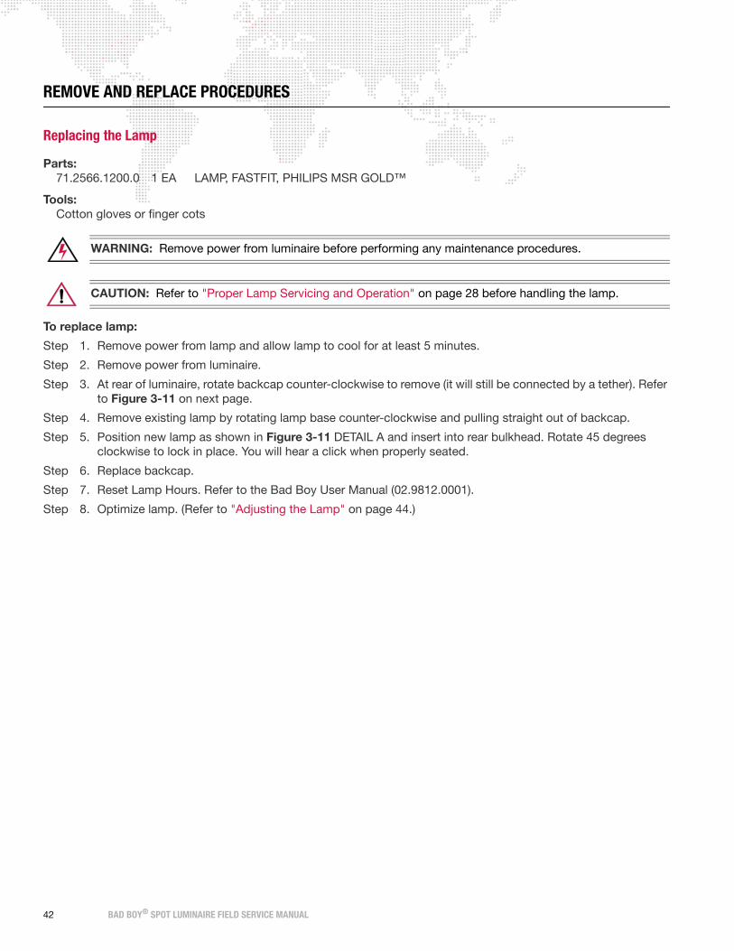
REMOVE AND REPLACE PROCEDURES
Replacing the Lamp
Parts:
71.2566.1200.0 1 EA LAMP, FASTFIT, PHILIPS MSR GOLD™
Tools:
Cotton gloves or finger cots
WARNING: Remove power from luminaire before performing any maintenance procedures.
CAUTION: Refer to "Proper Lamp Servicing and Operation" on page 28 before handling the lamp.
To replace lamp:
Step 1. Remove power from lamp and allow lamp to cool for at least 5 minutes.
Step 2. Remove power from luminaire.
Step 3. At rear of luminaire, rotate backcap counter-clockwise to remove (it will still be connected by a tether). Refer
to Figure 3-11 on next page.
Step 4. Remove existing lamp by rotating lamp base counter-clockwise and pulling straight out of backcap.
Step 5. Position new lamp as shown in Figure 3-11 DETAIL A and insert into rear bulkhead. Rotate 45 degrees
clockwise to lock in place. You will hear a click when properly seated.
Step 6. Replace backcap.
Step 7. Reset Lamp Hours. Refer to the Bad Boy User Manual (02.9812.0001).
Step 8. Optimize lamp. (Refer to "Adjusting the Lamp" on page 44.)
42 BAD BOY® SPOT LUMINAIRE FIELD SERVICE MANUAL

CAUTION: Wear cotton gloves or finger cots while servicing lamp. Touching the lamp glass with bare fingers
will leave oil and cause the lamp to explode or burn out early. If touched, use alcohol to thoroughly clean
glass.
Figure 3-11: Replacing the Lamp
Backcap
Lamp
Lamp Base
CAUTION:Do not touch lamp orreflector with bare fingers.
CAUTION:Allow lamp to coolbefore servicing.
Wing (Wide)
Wing (Thin)Lamp Base
Turn 45° Clockwise. Base willclick when properly seated.
DETAIL A: LAMP ORIENTATION
BAD BOY® SPOT LUMINAIRE FIELD SERVICE MANUAL 43

Adjusting the Lamp
After a new lamp is installed, it will be necessary to align the lamp in order to center and flatten the hot spot. Knobs
located at the luminaire’s backcap allow for adjustment.
Tools:
none
WARNING: Backcap may be HOT during lamp operation.
To adjust lamp:
Step 1. Power up luminaire and allow to warm up for at least ten minutes.
Step 2. Set intensity to 100%.
Step 3. Position beam on a white wall at a distance of 10' to 20'.
Step 4. Using control console, open beam size iris, set zoom for mid-range, and adjust for hard edge.
Step 5. At backcap, using horizontal (X) and vertical (Y) knobs, adjust hot spot to center of beam (Figure 3-12.)
Step 6. Using focus (Z) knob, adjust beam to flatten hot spot.
Figure 3-12: Adjusting the Lamp
Note: Be sure to reset Lamp Hours when installing a new lamp.
X
Y
Z
44 BAD BOY® SPOT LUMINAIRE FIELD SERVICE MANUAL

Replacing a Gobo
Parts:
Standard or Custom Gobo(s), as required.
(Refer to "Standard Gobo Wheel Configuration" on page 11.)
Tools:
#2 Phillips screwdriver
Cotton gloves or finger cots
WARNING: Remove power from luminaire before performing any maintenance procedures.
To replace a gobo:
Step 1. Remove power from luminaire.
Step 2. Locate appropriate head cover door for access to Rotating Gobo Wheel 1 (R1) or Rotating Gobo Wheel 2
(R2) as shown in Figure 3-13. (Doors are identified by a label.) Turn captive screw to open door.
CAUTION: Do not touch gobos with bare fingers. Wear cotton gloves or finger cots when handling.
Step 3. Rotate wheel until desired gobo is accessible.
Step 4. Rotate Color Wheels so that their "open" position lines up next to the gobo you wish to replace. (This will
avoid potential damage to the adjacent wheels as the gobo is being replaced.)
Figure 3-13: Accessing Gobo and Designer Color Wheels
Head Cover DoorR1 Wheel Access
Head Cover DoorR2 and Designer Wheel Access
X
Z
Captive Screw
Captive Screw
BAD BOY® SPOT LUMINAIRE FIELD SERVICE MANUAL 45

Step 5. Using fingers, grasp frame of gobo and pull out of wheel (Figure 3-14).
Figure 3-14: Replacing a Gobo
Step 6. Noting proper orientation, insert new gobo into wheel. Ensure that the "tongue" of the gobo clip goes under
the retaining plate (under the sun gear). Press and gently rotate the gobo bearing to help mesh the gobo
gear to the sun gear. Refer to Figure 3-15 on next page for an overview of gobo positions and alignment.
Step 7. Close head cover access door.
Gobo
Open Hole (no gobo)
Wheel
Note: Drawing is flipped 180°for clarity purposes.
Carrier
Sun Gear
Locking Tab
TongueTab
1
23
4
5
6 7
Retaining Plate
46 BAD BOY® SPOT LUMINAIRE FIELD SERVICE MANUAL

CAUTION: The gobos must be seated properly, especially the gear mesh.
Figure 3-15: Gobo Positions and Alignment
2
5
7
6
OPEN
1
2
3
OPEN
1
2
3
4
5
6
7
4
1
2
3
4
5
6
7
OPEN
BAD BOY® SPOT LUMINAIRE FIELD SERVICE MANUAL 47

Replacing a Designer Color Filter
Parts:
Designer Color Filter(s), as required.
(Refer to "Designer Color Wheel Standard Configuration" on page 10.)
Tools:
#2 Phillips screwdriver
Cotton gloves or finger cots
WARNING: Remove power from luminaire before performing any maintenance procedures.
To replace a designer color filter:
Step 1. Remove power from luminaire.
Step 2. Locate appropriate head cover door for
access to Designer Color Wheel as shown
in Figure 3-13 on page 45. (Doors are
identified by a label.) Turn captive screw to
open door.
CAUTION: Do not touch color filters with
bare fingers. Wear cotton gloves or finger
cots when handling.
Step 3. Rotate wheel until desired designer color
filter is accessible.
Step 4. Rotate Color and Gobo 2 Wheels so that
their "open" position lines up next to the
designer color filter you wish to replace.
(This will avoid potential damage to the
adjacent wheels as the filter is being
replaced.)
Step 5. Using fingers, grasp frame of color filter
and pull out of wheel hub (Figure 3-16).
Step 6. Noting proper orientation of carrier, insert
new designer color filter into position and
push until carrier clicks into place. Refer to
Figure 3-17 on next page for an overview
of designer filter positions.
Step 7. Close head cover access door.
Designer Color Filter
Wheel Hub
Note: Drawing is flipped 180°for clarity purposes.
Carrier
Figure 3-16: Removing Designer Color Filter
Open Hole (no filter)
1
2
3
4
5
6 7
48 BAD BOY® SPOT LUMINAIRE FIELD SERVICE MANUAL

Figure 3-17: Installing Designer Color Filter
6
5
4
7
OPEN
1
2
3
EXPLODED VIEW
BAD BOY® SPOT LUMINAIRE FIELD SERVICE MANUAL 49

Replacing the Front Glass
Parts:
12.9812.0629 1 EA RETAINER, FRONT GLASS PAINTED
41.9812.0628 1 EA FRONT GLASS
Tools:
Hook & Pick tool
WARNING: Remove power from luminaire before performing any maintenance procedures.
To replace the Front Glass:
Step 1. Remove power from luminaire and allow components to cool for at least 5 minutes.
Step 2. Position luminaire head so that Front Glass is facing upward. (To prevent it from falling onto the floor when
the Retaining Ring is removed in the next step.)
Step 3. Insert hook & pick tool under notch in Front Lens Retaining Ring. Carefully remove Retaining Ring.
Step 4. Remove Front Glass.
Step 5. Install new Front Glass by doing steps in reverse.
Note: Clean Front Glass with OptiMax™ Ultra Pure Cleaning Solution and Micro Fiber cloth only. DO NOT use window cleaner! Refer to "Cleaning the Lenses" on page 36 for more information.
Figure 3-18: Removing Front Glass
Front Glass
Retaining
Notch
Ring
50 BAD BOY® SPOT LUMINAIRE FIELD SERVICE MANUAL

Replacing the Wheel Stack
Parts:
21.9812.0620 1 EA ASSY, WHEEL STACK, LESS GOBOS (standard luminaire version)
21.9812.0696 1 EA ASSY, CMY WHEEL STACK, LESS GOBOS (CMY luminaire version)
Tools:
#2 Philips screwdriver
9/64" Allen wrench, T-bar
WARNING: Remove power from luminaire before performing any maintenance procedures.
To replace the Wheel Stack Assembly:
Step 1. Remove power from luminaire and allow components to cool for at least 5 minutes.
Step 2. Remove both Head Covers. (Refer to "Removing the Head Covers" on page 30.)
Step 3. At top of head assembly, disconnect the following Wheel Stack wiring (Figure 3-19):
a. From Zoom Controller PCB:
1) Zoom Cable.
2) CAN Bus Cable.
b. From Wheel Stack Motherboard:
1) Tip Pinch Fan Cable.
2) Main Fan Cable.
3) Main Power Cable.
4) Two CAN Bus Cables.
c. Free cable harness from twist-lock holders and lay cables out of the way so that Wheel Stack Assembly
can be removed.
Step 4. At bottom of head assembly, disconnect the following Wheel Stack Wiring (Figure 3-19):
a. Frost Sensor Cable.
b. Frost Motor Cable.
c. Free sensor/motor cable harness from tie-wrap saddle on back of motor.
BAD BOY® SPOT LUMINAIRE FIELD SERVICE MANUAL 51

Figure 3-19: Disconnecting Wheel Stack Wiring
J6
J2
J3J
4
J29J28
J1
J49J40
J30
Frost Motor
Frost Sensor
Frost Motor
Fan, Power
Zoom Controller PCB
Wheel Stack
Twist-Lock Holder
Fan Wire Harness
& Control Cables
Wheel Stack Assembly Cable
Cable
Motherboard
52 BAD BOY® SPOT LUMINAIRE FIELD SERVICE MANUAL

Step 5. At Wheel Stack Assembly, remove four 8-32 x 1/2" socket head screws (Figure 3-20).
Step 6. Verify that Lens Group 1 will not interfere with removal of Wheel Stack Assembly. If lenses are in the way,
turn Group 1 pulley until lenses are clear.
Step 7. Grasp Wheel Stack Assembly on either side and lift straight up and out of luminaire head.
Figure 3-20: Removing Wheel Stack Assembly
Step 8. Replace Wheel Stack Assembly by doing steps in reverse.
Wheel Stack Assembly
8-32 x 1/2" SCB Screw (4)
Lens Group 1
C
M Y
Depending on the Bad Boy luminaire model, the Wheel Stack Assembly will be different. The CMY Wheel Stack can be identified by a label on the outer plate.
NOTE:
BAD BOY® SPOT LUMINAIRE FIELD SERVICE MANUAL 53

To pack Wheel Stack Assembly for shipping:
If a Wheel Stack Assembly is to be shipped to a PRG Service Center, a Wheel Stack Road Case (20.9812.1229)
should be used. This will protect the fragile components of the Wheel Stack Assembly during storage, transport and
shipping.
Step 1. Carefully lower Wheel Stack Assembly into road case as shown in Figure 3-21.
Step 2. Document luminaire serial number and reason for failure.
Step 3. Apply a pre-printed shipping label to top of case. (Labels can be found in a plastic bag taped to the inside
of the road case.)
Figure 3-21: Packing Wheel Stack Road Case
ADDRESSLABEL
Address Label
C
M Y
Depending on the Bad Boy luminaire model, the Wheel Stack Assembly will be different. The CMY Wheel Stack can be identified by a label on the outer plate.
NOTE:
54 BAD BOY® SPOT LUMINAIRE FIELD SERVICE MANUAL

Replacing the Frost/Diffuser Paddle
Parts:
22.9812.0557 1 EA ASSY, DIFFUSER PADDLE
Tools:
#2 Philips screwdriver
2mm Allen wrench
Spacer Tool (10.9812.0584)
WARNING: Remove power from luminaire before performing any maintenance procedures.
To replace the Frost/Diffuser Paddle Assembly:
Step 1. Remove power from luminaire and allow components to cool for at least 5 minutes.
Step 2. Remove R2/Designer Wheel Head Cover. (Refer to "Removing the Head Covers" on page 30.)
Figure 3-22: Removing Frost/Diffuser Paddle Assembly
Step 3. Disconnect Frost Sensor Cable.
Step 4. Rotate Frost/Diffuser Paddle Assembly to access set screw. Loosen set screw.
Step 5. Ensure paddle will clear Frost Sensor PCB (rotate if necessary), and remove Frost/Diffuser Paddle
Assembly.
Step 6. Replace Frost/Diffuser Paddle Assembly as follows:
a. Slide new Paddle Assembly onto motor shaft.
b. Insert Spacer Tool between Paddle Assembly and motor, aligning the tool’s notch over the motor shaft.
c. Tighten set screw.
d. Remove Spacer Tool.
Frost/Diffuser
Zoom Assembly
Paddle AssemblySet Screw
Frost Sensor
BAD BOY® SPOT LUMINAIRE FIELD SERVICE MANUAL 55

Step 7. Test clearance and operation as follows:
a. Manually slide Lens Group 3 toward Paddle Assembly until it come to rest on the stop.
b. Rotate Paddle Assembly to test clearance. Paddle should not touch lenses.
c. If paddle is contacting the lenses, loosen set screw and repeat Steps 6 and 7.
56 BAD BOY® SPOT LUMINAIRE FIELD SERVICE MANUAL

Replacing the Diffuser Sensor PCB
Parts:
24.9812.0570 1 EA PCB ASSY, DIFFUSER SENSOR
Tools:
#2 Philips screwdriver
Small slotted screwdriver
WARNING: Remove power from luminaire before performing any maintenance procedures.
CAUTION: Always use anti-static precautions when working with PCBs.
To replace the Diffuser Sensor:
Step 1. Remove power from luminaire and allow components to cool for at least 5 minutes.
Step 2. Remove R1 Head Cover. (Refer to "Removing the Head Covers" on page 30.)
Step 3. At Diffuser Sensor, disconnect cable (Figure 3-23).
Step 4. Remove Diffuser Sensor by removing two 4-40 x 3/16" PFSS screws.
Step 5. Replace Diffuser Sensor by doing steps in reverse. Make sure header is below 4-40- x 3/16" screws as shown in Figure 3-23.
Figure 3-23: Removing Diffuser Sensor
ORIENTATION
REAR VIEW
HEADER SIDE
Diffuser Sensor
4-40 x 3/16"PFSS Screw (2)
Diffuser Sensor
Diffuser Sensor CableNote position of header during re-installation
CAUTION:Use anti-static precautions when working with PC boards.
BAD BOY® SPOT LUMINAIRE FIELD SERVICE MANUAL 57

Replacing the Zoom Controller PCB
Parts:
24.9812.0511.0 1 EA PCB ASSY, ZOOM CONTROLLER
Tools:
#1 and #2 Philips screwdrivers
WARNING: Remove power from luminaire before performing any maintenance procedures.
CAUTION: Always use anti-static precautions when working with PCBs.
To replace the Zoom Controller PCB:
Step 1. Remove power from luminaire and allow components to cool for at least 5 minutes.
Step 2. Remove R2/Designer Wheel Head Cover. (Refer to "Removing the Head Covers" on page 30.)
Step 3. At Zoom Controller PCB, disconnect all cables.
Step 4. Remove Zoom Controller PCB by removing four 4-40 x 1/4" PPB screws. (Note the placement of the tie-
wrap which secures the Zoom Sensor 4 cable under the Zoom PCB corner screw.)
Step 5. Replace Zoom Controller PCB by doing steps in reverse. When installing new Zoom Controller PCB, be sure to secure Zoom Sensor 4 cable tie-wrap under Zoom Controller PCB corner screw.
Figure 3-24: Removing Zoom Controller PCB
J10J18
J5
J8J16 3
J9J17 J14
J4
J1
J6
J2 J3
J15J11J7
J12
Zoom Controller PCB
4-40 x 1/4" PPB Screw (4)Zoom Controller PCB Wiring
CAUTION:Use anti-static precautions when working with PC boards.
58 BAD BOY® SPOT LUMINAIRE FIELD SERVICE MANUAL

Replacing a Zoom Sensor PCB
The Zoom Assembly contains four Zoom Sensor PCBs (one for each Zoom Lens Group). This procedure provides
instructions for changing any one of the four sensors.
Note that two (2) Zoom Sensor PCBs are located on the top side of the Head Assembly (under the R1 cover) and two
(2) Zoom Sensor PCBs are located on the bottom side of the Head Assembly (under the R2 cover).
Parts:
24.9812.0510 4 EA 24.9812.0510
Tools:
#2 Philips screwdriver
#1 Right-angle Philips screwdriver or #1 Philips screwdriver, as required
WARNING: Remove power from luminaire before performing any maintenance procedures.
CAUTION: Always use anti-static precautions when working with PCBs.
CAUTION: NEVER adjust the brass spring-loaded standoff. It is set at the factory.
To replace a Zoom Sensor:
Step 1. Remove power from luminaire and allow components to cool for at least 5 minutes.
Step 2. To remove Zoom Sensors 1 or 3:
a. Remove R1 Head Cover. (Refer to "Removing the Head Covers" on page 30.)
b. At required Zoom Sensor, disconnect cable from header (Figure 3-25).
c. Remove Zoom Sensor by removing two 2-56 x 1/4" PPZ screws.
Step 3. To remove Zoom Sensor 2:
a. Remove R2/Designer Wheel Head Cover. (Refer to "Removing the Head Covers" on page 30.)
b. At Zoom Controller PCB, remove four 4-40 x 1/4" PPB screws. (The PCB will still be connected by
wiring.) Move Zoom Controller PCB to the side in order to access Zoom Sensor 2 as shown in Figure 3-
26.
c. At Zoom Sensor, disconnect cable from header (Figure 3-26).
d. Remove Zoom Sensor by removing two 2-56 x 1/4" PPZ screws.
Step 4. To remove Zoom Sensor 4:
a. Remove R2/Designer Wheel Head Cover. (Refer to "Removing the Head Covers" on page 30.)
b. At Zoom Sensor, disconnect cable from header (Figure 3-26).
c. Remove Zoom Sensor by removing two 2-56 x 1/4" PPZ screws.
Step 5. Replace a Zoom Sensor by doing steps in reverse.
BAD BOY® SPOT LUMINAIRE FIELD SERVICE MANUAL 59

Figure 3-25: Removing Zoom Sensors 1 & 3
R1 Head Cover
8-32 x 3/8" PPB Screw (2 ea)
Zoom Sensor2-56 x 1/4"PPZ Screw (2)
Zoom Sensor
Zoom Sensor
CAUTION:Hand tighten only. DO NOT use a power tool on Head Cover screws.
CAUTION:Use anti-static precautions when working with PC boards.
60 BAD BOY® SPOT LUMINAIRE FIELD SERVICE MANUAL

]
Figure 3-26: Removing Zoom Sensors 2 & 4
Zoom Sensor
2-56 x 1/4"PPZ Screw (2)
Zoom Controller PCB
4-40 x 1/4" PPB Screw (4)
Zoom Sensor
CAUTION:Use anti-static precautions when working with PC boards.
BAD BOY® SPOT LUMINAIRE FIELD SERVICE MANUAL 61

Replacing the Main Head Fan
Parts:
23.9812.0993 1 EA ASSY, MAIN HEAD FAN
Tools:
#2 Philips screwdriver
5/32" Allen T-wrench
WARNING: Remove power from luminaire before performing any maintenance procedures.
To replace the Main Head Fan:
Step 1. Remove power from luminaire and allow components to cool for at least 5 minutes.
Step 2. Remove Head Covers. (Refer to "Removing the Head Covers" on page 30.)
Step 3. Remove lamp. (Refer to "Replacing the Lamp" on page 42.)
Step 4. Remove X, Y, Z Adjustment Knobs and Aft Cover. (Refer to "Removing the Aft Cover" on page 31.)
Figure 3-27: Removing Main Head Fan
Step 5. At Motherboard PCB, disconnect Main Head Fan Cable (labeled HI TEMP).
Step 6. Release cable from twist-lock cable ties and feed through hole in Aft Assembly.
Step 7. Remove Main Head Fan by removing three 6-32 x 1/4" PPB screws.
X
Z
Y
Aft Cover10-32 x 3/8" SHCS Screw (4)
Main Head Fan
6-32 x 1/4" PPB Screw (3)
Z Knob(no washer)
Y Knob
X Knob
(longest threads)
62 BAD BOY® SPOT LUMINAIRE FIELD SERVICE MANUAL

CAUTION: The Main Head Fan has been upgraded. Be sure to install only the latest hi-temp fan. The hi-
temp fan can be identified by a red ring around the spinner.
Note: In order to prevent heat from escaping the rear bulkhead area and moving into the main head assembly,
aluminum tape has been used to seal the backcap perimeter, fan wire hole, and back side of pinch fan. Re-apply new
tape before re-installing the Aft Cover. Refer to technical bulletin BAD-002 for more information.
Step 8. Replace Main Head Fan by doing steps in reverse. Be sure to re-apply aluminum sealing tape as noted above.
BAD BOY® SPOT LUMINAIRE FIELD SERVICE MANUAL 63

Replacing the Tip Pinch Fan (Original Version)
The Tip Pinch Fan has been upgraded in most Bad Boy Luminaires. Refer to the procedure on the following page if
the new Hi-Temp fan version has already been installed.
Parts:
23.9812.0990 1 EA ASSY, TIP PINCH FAN, 12V
Tools:
#2 Philips screwdriver
WARNING: Remove power from luminaire before performing any maintenance procedures.
To replace the Tip Pinch Fan:
Step 1. Remove power from luminaire and allow components to cool for at least 5 minutes.
Step 2. Remove Head Covers. (Refer to "Removing the Head Covers" on page 30.)
Step 3. Remove Wheel Stack Assembly. (Refer to "Replacing the Wheel Stack" on page 51.)
Step 4. Disconnect Tip Fan Cable (labeled TIP FAN J49) and release from twist-lock cable ties.
Step 5. Remove Tip Pinch Fan by removing two 6-32 x 1-1/8" PPZ screws.
Figure 3-28: Removing Tip Pinch Fan
Step 6. Replace fan by doing steps in reverse.
Tip Pinch Fan
Fan Cable
6-32 x 1-1/8" PPZ Screw (2)
Aft Assembly
Note: Be sure the new fan has
aluminum tape covering the back
and/or aluminum tape is blocking
the fan hole on the Aft Assembly.
Refer to technical bulletin BAD-002
for more information.
64 BAD BOY® SPOT LUMINAIRE FIELD SERVICE MANUAL

Replacing the Tip Pinch Fan (Hi-Temp Version)
The Tip Pinch Fan has been upgraded in most Bad Boy Luminaires. If the Hi-Temp fan version has not been installed
yet, refer to the procedure on the previous page.
Parts:
23.9812.0994 1 EA ASSY, HI-TEMP TIP PINCH FAN, 12V
Tools:
#2 Philips screwdriver
WARNING: Remove power from luminaire before performing any maintenance procedures.
To replace the Tip Pinch Fan:
Step 1. Remove power from luminaire and allow components to cool for at least 5 minutes.
Step 2. Remove Head Covers. (Refer to "Removing the Head Covers" on page 30.)
Step 3. Remove Wheel Stack Assembly. (Refer to "Replacing the Wheel Stack" on page 51.)
Step 4. Disconnect Tip Fan Cable (labeled TIP FAN J49) and release from twist-lock cable ties.
Step 5. Remove Tip Pinch Fan (and Insulator) by removing two 6-32 x 3/8" screws.
Figure 3-29: Removing Tip Pinch Fan
Step 6. Replace fan (and Insulator) by doing steps in reverse.
Tip Pinch Fan
Fan Cable
Aft Assembly
Insulator
6-32 x 3/8" ZincSocket Head Screw
6-32 x 3/8" ZincButton Head Screw
Note: An O-ring was added
to replace the aluminum tape.
BAD BOY® SPOT LUMINAIRE FIELD SERVICE MANUAL 65

Replacing the UV/IR Window Assembly
Parts:
22.9812.0616 1 EA ASSY, UV/IR WINDOW
Tools:
#2 Philips screwdriver
#1 Philips screwdriver, stubby
WARNING: Remove power from luminaire before performing any maintenance procedures.
CAUTION: Do not touch UV/IR Window with bare fingers. If dirty, clean with OptiMax™ Ultra Pure Cleaning
Solution and a Micro Fiber cloth.
To replace the UV/IR Window Assembly:
Step 1. Remove power from luminaire and allow components to cool for at least 5 minutes.
Step 2. Remove Head Covers. (Refer to "Removing the Head Covers" on page 30.)
Step 3. Remove Wheel Stack Assembly. (Refer to "Replacing the Wheel Stack" on page 51.)
Step 4. Remove UV/IR Assembly by removing four 4-40 x 1/4" PPSS screws (Figure 3-30).
Step 5. Replace UV/IR Assembly by doing steps in reverse. Be sure to align fan ducts.
Figure 3-30: Removing UV/IR Window Assembly
UV/IR WindowAssembly
4-40 x 1/4" PPSS Screw (4)
Duct Hole
Fan
INTERIOR DETAIL VIEWDuct
66 BAD BOY® SPOT LUMINAIRE FIELD SERVICE MANUAL

Replacing the Reflector
Parts:
42.9812.0160 1 EA REFLECTOR, 36 LUNES, COATED
Tools:
#2 Phillips screwdriver, long or #2 Philips screwdriver, right-angle
Cotton gloves or finger cots
WARNING: Remove power from luminaire before performing any maintenance procedures.
CAUTION: Do not touch reflector with bare fingers. If dirty, clean with OptiMax™ Ultra Pure Cleaning
Solution and a Micro Fiber cloth.
To replace the Reflector:
Step 1. Remove power from luminaire and allow components to cool for at least 5 minutes.
Step 2. Remove Aft Cover. (Refer to "Removing the Aft Cover" on page 31.)
Step 3. At Reflector, loosen four 6-32 x 1/4" PPB screws to free mounting clips (Figure 3-31).
Step 4. Remove Reflector by carefully sliding out from under XYZ Assembly. (Insulator will come loose during
removal. Do not lose Insulator.)
Step 5. Replace Reflector by doing steps in reverse.
Figure 3-31: Removing Reflector
Reflector
Mounting
6-32 x 1/4"
Insulator
Head Assy
Clip (4)
PPB Screw (4)
XYZ Assembly
BAD BOY® SPOT LUMINAIRE FIELD SERVICE MANUAL 67

Replacing a 2A Fuse
2 Amp fuses are located on the Zoom Controller PCB (4 each) and the Wheel Controller PCB (4 each).
Parts:
70.3769.0002.0 8 EA FUSE, 2AMP SLO-BLO
Tools:
#2 Philips screwdriver
Needle-nose pliers, small
WARNING: Remove power from luminaire before performing any maintenance procedures.
To replace a 2A Fuse:
Step 1. Remove power from luminaire and allow components to cool for at least 5 minutes.
Step 2. Remove Head Cover(s) as required. (Refer to "Removing the Head Covers" on page 30.)
Step 3. At required PCB, use needle-nose pliers to carefully remove and replace 2A fuse.
Figure 3-32: Removing 2A Fuse
2A Fuse
CAUTION:Use anti-static precautions when working with PC boards.
68 BAD BOY® SPOT LUMINAIRE FIELD SERVICE MANUAL

Replacing the 3A Fuse
The 3 Amp fuse is located on the Pan/Tilt Controller PCB.
Parts:
70.3769.0003.0 1 EA FUSE, 3AMP SLO-BLO
Tools:
Needle-nose pliers, small
WARNING: Remove power from luminaire before performing any maintenance procedures.
To replace the 3A Fuse:
Step 1. Remove power from luminaire and allow components to cool for at least 5 minutes.
Step 2. At Pan Yoke Leg, remove Yoke Leg Cover.
Step 3. At Pan/Tilt Controller PCB, use needle-nose pliers to carefully remove and replace 3A fuse.
Figure 3-33: Removing 3A Fuse
3A Fuse
Pan/Tilt Controller PCB
CAUTION:Use anti-static precautions when working with PC boards.
BAD BOY® SPOT LUMINAIRE FIELD SERVICE MANUAL 69

Replacing the EMI Ballast Enclosure
Parts:
23.9812.0810 1 EA ASSY, EMI BALLAST ENCLOSURE
Tools:
#2 Philips screwdriver
Wire cutters
Tie-Wraps
Loctite 242
WARNING: Remove power from luminaire before performing any maintenance procedures.
To replace the EMI Ballast Enclosure:
Step 1. Remove power from luminaire and allow components to cool for at least 5 minutes.
Step 2. Remove both Upper Enclosure Covers. (Refer to "Removing the Enclosure Covers" on page 32.)
Step 3. Disconnect the following wiring (Figure 3-34):
a. APS Cable.
b. Two Fan Cables.
c. Ground Cable.
d. Lamp Power Ballast Output Cables (white and black).
Step 4. At EMI Ballast Enclosure, remove four 10-32 x 3/8" PPB Black SEMS screws. (Assembly will still be
connected by wiring.)
Step 5. Move EMI Ballast Enclosure away from the luminaire as far as the cabling will allow. (This will provide
access to disconnect the remaining cables.)
Step 6. At EMI Filter, disconnect two output cables.
Step 7. Cut tie-wrap to free Lamp Power Ballast Output Cables.
Step 8. Remove EMI Ballast Enclosure.
CAUTION: Be careful to maintain correct polarity of the lamp wires.
Step 9. Replace EMI Ballast Enclosure by doing steps in reverse. Use Loctite 242 when re-installing ground wire as shown in Figure 3-34.
70 BAD BOY® SPOT LUMINAIRE FIELD SERVICE MANUAL

Figure 3-34: Removing EMI Ballast Enclosure
FRONT VIEW
1 2
WHITEBLACK
CABLE LAYOUT - REAR VIEW
25-9812-0987-02
AC NEUT
AC LINE
EMI FILTERFROM
PCB
CHASSISGND STUD
FROM
TO LEFTEXTENSION FAN 1
BALLAST CONTROL
BLK L
WHT
SIDE VIEW
TO
BALLAST CONTROLCABLE ASSY
25-9812-0966-02
N
BALLAST POLARITY
2
1
EXTENSION FAN 2TO RIGHT
BALLAST CONTROL25-9812-0987-03
EMI Ballast Enclosure
10-32 x 3/8" PPBBlack SEMS Screw (4)
EMI Filter
APS
Fan
GroundEMI
Ground(Loctite 242)
Fan
EMI Filter
LAMP WIRES
EMI OutputCables
BAD BOY® SPOT LUMINAIRE FIELD SERVICE MANUAL 71

Replacing the Interface/LVS Module
Parts:
23.9812.0812 1 EA ASSY, INTERFACE/LVS MODULE
Tools:
#2 Philips screwdriver
WARNING: Remove power from luminaire before performing any maintenance procedures.
To replace the Interface/LVS Module:
Step 1. Remove power from luminaire and allow components to cool for at least 5 minutes.
Step 2. Remove Intake Cover. (Refer to "Removing the Enclosure Covers" on page 32.)
Step 3. At Interface/LVS Module, remove four 10-32 x 3/8" PPB SEMS screws (Figure 3-35).
Step 4. At left side of Interface/LVS Module, disconnect the following wiring:
a. Fan cable.
b. APS Control Line cable.
c. Neutral (white) cable.
d. Line (black) cable.
e. Ground cable.
Step 5. At right side of Interface/LVS Module, disconnect the following wiring:
a. Fan cable.
b. CAN Bus cable.
c. Power cables (red and black).
Step 6. Remove Interface/LVS Module from enclosure.
Note: The battery pack cable is intentionally NOT connected. Do not re-connect.
Step 7. Replace Interface/LVS Module by doing steps in reverse. Do not connect battery pack cable. Leave this cable disconnected.
72 BAD BOY® SPOT LUMINAIRE FIELD SERVICE MANUAL

Figure 3-35: Removing Interface/LVS Module
6
7
8
CN3
LVS DETAIL
NL
POWERCONGND
WHITE
BLACK
GRN/YEL
GND
LVSGND
N
BLK
WHT
NWHT
BLK
GND
Fan
Fan
CAN Bus
Low Voltage DC Output
AC Line Input
L
CN1
N
2
1
3
4
5
FA
N 1
RED
BLACK
10-32 x 3/8" PPB SEMS Screw (4)
Interface/LVS Module
Enclosure
Power Cables:
Do not disconnect cablesfrom positions 4 & 5
BAD BOY® SPOT LUMINAIRE FIELD SERVICE MANUAL 73

Replacing the Ignitor PCB
Parts:
24.9812.0775 1 EA PCB ASSY, SOLID STATE IGNITOR
Tools:
#2 Philips screwdriver
1/4" Nutdriver
Loctite 242
WARNING: Remove power from luminaire before performing any maintenance procedures.
CAUTION: Always use anti-static precautions when working with PCBs.
To replace the Ignitor PCB:
Step 1. Remove power from luminaire and allow components to cool for at least 5 minutes.
Step 2. At Tilt Yoke Leg, remove Yoke Leg Cover.
Step 3. At Ignitor Cover, remove four 6-32 nylon insert nuts and four #6 nylon washers. Remove Ignitor Cover.
Figure 3-36: Removing Ignitor PCB
CAUTION: Be careful to maintain correct polarity of the lamp wires.
Step 4. At Ignitor PCB, disconnect input and output cables.
Step 5. Remove four 1/4" 6-32 hex standoffs and remove Ignitor PCB.
24V
AED ORN
B
HOT SW
TO
BU
LB
TO
J3 J4
J1
J1
J2J2
J2
3NC
WHT6
WHT9IGNITOR
INPUT
BALLASTOUTPUT
Ignitor PCB
Ignitor OutputCable Assembly
Ignitor InputCable Assembly
1/4" Hex 6-32
6-32 NylonInsert Nut (4)
#6 NylonWasher (4)
Standoff (4) - Loctite 242
Cover
Ignitor PCB
Yoke Leg(Tilt Side)
CAUTION:Use anti-static precautions when working with PC boards.
74 BAD BOY® SPOT LUMINAIRE FIELD SERVICE MANUAL

Step 6. Replace Ignitor PCB by doing steps in reverse. Use Loctite 242 when re-installing standoffs as shown in Figure 3-36.
Note: Be sure you install the NEW Ignitor (24.9812.0775). This component has been upgraded.
BAD BOY® SPOT LUMINAIRE FIELD SERVICE MANUAL 75

Replacing the Pan/Tilt Controller PCB
Parts:
24.9812.0765 1 EA PCB ASSY, CONTROLLER PAN/TILT
Tools:
#2 Philips screwdriver
WARNING: Remove power from luminaire before performing any maintenance procedures.
CAUTION: Always use anti-static precautions when working with PCBs.
To replace the Pan/Tilt Controller PCB:
Step 1. Remove power from luminaire and allow components to cool for at least 5 minutes.
Step 2. At Tilt Yoke Leg, remove Yoke Cover.
Step 3. At Pan/Tilt Controller PCB, disconnect all cables.
Step 4. Remove Pan/Tilt Controller PCB by removing four 6-32 x 5/16" PPZ screws (Figure 3-37).
Step 5. Replace Pan/Tilt Controller PCB by doing steps in reverse.
Figure 3-37: Removing Pan/Tilt Controller PCB
Pan/Tilt
6-32 x 5/16" PPZ Screw (4)
Controller PCB
CAUTION:Use anti-static precautions when working with PC boards.
76 BAD BOY® SPOT LUMINAIRE FIELD SERVICE MANUAL

Replacing the Pan/Tilt COT Sensor PCB
Parts:
24.9679.0750 1 EA PCB ASSY, PAN/TILT COT SENSOR
Tools:
#1 and #2 Philips screwdrivers
WARNING: Remove power from luminaire before performing any maintenance procedures.
CAUTION: Always use anti-static precautions when working with PCBs.
To replace the Pan/Tilt COT (Center of Travel) Sensor PCB:
Step 1. Remove power from luminaire and allow components to cool for at least 5 minutes.
Step 2. At Pan Yoke Leg, remove Yoke Leg Cover.
Step 3. Remove Cable Routing Plate by removing four 10-32 x 3/8" PFZ screws (Figure 3-38). Plate will remain
attached by cabling, so just allow to it hang out of the way during this procedure.
Note: The Counterweight was added as a retrofit. If the Counterweight is not present, it should be added. Refer to
technical bulletin BAD-001 for instructions.
Figure 3-38: Removing Pan/Tilt COT Sensor PCB
Step 4. At Pan/Tilt Controller PCB, disconnect Pan/Tilt COT Sensor cable.
Step 5. At outside of yoke leg, remove two 4-40 x 3/8" PFZ screws (which secure standoff to yoke leg). This will free
Pan/Tilt COT Sensor PCB Assembly.
Step 6. Remove two standoffs from Pan/Tilt COT Sensor PCB Assembly by removing two 4-40 x
1/4" PPZ screws.
Counterweight / Cable Routing Plate
Handle
Pan/Tilt COT Sensor PCB Assy
Pan/TiltController PCB
10-32 x 5/8"
Standoff (2)
4-40 x 1/4"PPZ Screw (2)
4-40 x 3/8" PFZ Screw (2)PFZ Screw (4)Yoke Leg(Pan Side)
CAUTION:Use anti-static precautions when working with PC boards.
BAD BOY® SPOT LUMINAIRE FIELD SERVICE MANUAL 77

Step 7. Install standoffs on new Pan/Tilt COT Sensor PCB Assembly.
Step 8. Install new Pan/Tilt COT Sensor PCB Assembly by doing steps in reverse. When re-assembling, route Pan/Tilt COT Sensor cable BEHIND standoffs.
78 BAD BOY® SPOT LUMINAIRE FIELD SERVICE MANUAL

Replacing the Pan Drive Assembly
Parts:
21.9812.0718 1 EA ASSY, PAN DRIVE MECHANISM
Tools:
#2 Philips screwdriver
5/32" Allen wrench
7/16" open-ended wrench
Sonic Tension Meter, Model 507C (07.3082.1052.0)
WARNING: Remove power from luminaire before performing any maintenance procedures.
To replace the Pan Drive Assembly:
Step 1. Remove power from luminaire and allow components to cool for at least 5 minutes.
Step 2. Remove both Yoke Covers by loosening four captive screws (Figure 3-39).
Figure 3-39: Removing Yoke Covers, Handle and Pan Shield
Step 3. At Pan-Side Yoke Leg, remove Yoke Handle by removing two 10-32 x 5/8" PFZ screws.
Step 4. Remove Pan Shield by removing two 6-32 x 3/8" PFSS black screws and four 6-32 x 1/4" PPZ SEMS
screws.
Step 5. At Pan/Tilt Controller PCB, disconnect Pan Drive Assembly cable harness.
Step 6. Loosen Pan Cable Routing Plate by removing five 10-32 x 5/8" PFZ screws (Figure 3-40).
Yoke Cover
Yoke Handle
Pan Shield
Yoke Cover
10-32 x 5/8"PFZ Screw (2)
6-32 x 1/4" PPZSEMS Screw (4)
6-32 x 3/8" PFSSBlack Screw (2)
BAD BOY® SPOT LUMINAIRE FIELD SERVICE MANUAL 79

Step 7. Move Pan Cable Routing Plate out of the way enough to access belt and pulley.
Step 8. At Pan Drive Assembly, loosen (but do not completely remove) four 10-32 x 5/8" socket head screws. This
will begin to loosen the belt.
Step 9. Release belt tension by loosening two belt adjustment screws and slip belt off of pan pulley (Figure 3-41).
Step 10. Remove four 10-32 x 5/8" socket head screws and two #10 flat washers from Pan Drive Assembly.
Step 11. At Bus Bar, remove screw on left-hand side and loosen screw on right-hand side. Rotate Bus Bar up and
out of the way. (This will make it easier to remove the Pan Drive Assembly.)
Step 12. Remove Pan Drive Assembly from yoke.
Step 13. Replace Pan Drive Assembly by doing steps in reverse.
Step 14. Set proper belt tension. Refer to "Setting Pan/Tilt Belt Tension" on page 83.
Figure 3-40: Removing Pan Drive Assembly (View 1)
Pan Drive Assembly
10-32 x 5/8"PFZ Screw (5)
Pulley
Belt
10-32 x 5/8"Soc Cap Screw (2)
#10 Flat Washer (2)
DETAIL A
Pan CableRouting Plate
80 BAD BOY® SPOT LUMINAIRE FIELD SERVICE MANUAL

Figure 3-41: Removing Pan Drive Assembly (View 2)
J10
J11
J6
J1
PA
N
J8
J12
J3J2
J14J15
J7
TIL
T
J16
J9
J13
B
A
Pan Drive Assembly
Pan/Tilt PCB
Bus Bar
Belt Adjustment Screw (2)
Pan Drive Assembly
Remove screw androtate bus bar outof the way (optional).
BAD BOY® SPOT LUMINAIRE FIELD SERVICE MANUAL 81

Replacing the Tilt Drive Assembly
Parts:
21.9812.0719 1 EA ASSY, TILT DRIVE
Tools:
#2 Philips screwdriver
7/16" open-ended wrench
3/8" Nutdriver
Sonic Tension Meter, Model 507C (07.3082.1052.0)
WARNING: Remove power from luminaire before performing any maintenance procedures.
To replace the Tilt Drive Assembly:
Step 1. Remove power from luminaire and allow components to cool for at least 5 minutes.
Step 2. Remove both Yoke Covers by loosening four captive screws (Figure 3-39).
Step 3. At Tilt-Side Yoke Leg, remove Yoke Handle by removing two 10-32 x 5/8" PFZ screws (Figure 3-42).
Figure 3-42: Removing Tilt Drive Assembly
Yoke Handle
10-32 x 5/8"PFZ Screw (2)
Tilt Drive Assembly
10-32 Nylon
Tilt Pulley
Belt
#10 Flat Washer (4)
Insert Nut (4)
82 BAD BOY® SPOT LUMINAIRE FIELD SERVICE MANUAL

Step 4. Remove Pan Shield by removing two 6-32 x 3/8" PFSS black screws and four 6-32 x 1/4" PPZ SEMS
screws (Figure 3-39).
Step 5. At Pan/Tilt Controller PCB, disconnect Tilt Drive Assembly cable harness.
Step 6. At Tilt Drive Assembly, loosen (but do not completely remove) four 10-32 nylon insert nuts (Figure 3-42).
This will begin to loosen the belt.
Step 7. Release belt tension by loosening two belt adjustment screws and slip belt off of tilt pulley.
Step 8. Remove four 10-32 nylon insert nuts and four #10 flat washers from Tilt Drive Assembly.
Step 9. Remove Tilt Drive Assembly from yoke.
Step 10. Replace Tilt Drive Assembly by doing steps in reverse.
Step 11. Set proper belt tension. Refer to "Setting Pan/Tilt Belt Tension" on page 83.
Setting Pan/Tilt Belt Tension
Loose pan/tilt drive belts can create calibration problems. When the luminaire reaches the end of travel, excess belt
slack can produce a vibration causing the encoder to continue producing a movement output signal to the processor
(even though the luminaire is at its stop).
When properly set, the belt should not show bilateral deflection. Bilateral deflection may be observed by loosening the
tension adjustment bolt(s) and rotating the head assembly. As the head is rotated back and forth, tension is created
on one side and deflections are created on the other.
There are two ways to set proper belt tension:
1) Using a Sonic Tension Meter (recommended).
2) By manually tightening until no bilateral deflection is present.
When using the Sonic Tension Meter, it will be necessary to program separate presets for the Pan and Tilt Drive belts
as follows:
Tools:
7/16" open-ended wrench, orSonic Tension Meter, Model 507C (07.3082.1052.0)
CAUTION: Do not overtighten belt, pulley will break and/or bearings will fail.
To set belt tension using a meter:
Step 1. Set Pan and Tilt presets on the Tension Meter as given above.
Step 2. Orient head as shown in Figure 3-43 on next page.
Step 3. Slowly tighten belt adjustment bolt(s). Use Tension Meter to verify correct tension.
Preset Belt MassWidth
(mm)
Span
(mm)
Tension
(lbs.)
1 Pan Drive 4.1 15 109 80-100
2 Tilt Drive 4.1 15 326 80-100
BAD BOY® SPOT LUMINAIRE FIELD SERVICE MANUAL 83

CAUTION: Do not overtighten belt, pulley will break and/or bearings will fail.
To set belt tension manually:
Step 1. Orient head as shown in Figure 3-43.
Step 2. Manually move the luminaire head back and forth (tilt) or around (pan), noting the tension created on one
side of belt and deflections on the other.
Step 3. Using wrench, tighten belt adjustment bolt(s) until no bilateral deflection occurs..
Figure 3-43: Belt Tension Adjustment
Driven Pulley
Feed Side
Drive Pulley
Tension Side
of Belt
Deflections are presentwhen belt is loose.
TILT MECHANISM
PAN MECHANISM
of Belt
Orient head as shown
84 BAD BOY® SPOT LUMINAIRE FIELD SERVICE MANUAL

4.
ILLUSTRATED PARTS BREAKDOWNThis chapter provides illustrated parts breakdowns for all luminaire spares components.
+ OVERVIEW
+ PARTS BREAKDOWN

OVERVIEW
About this IPB
The Illustrated Parts Breakdown is intended for use with Field Service of the luminaire. The items identified here match
the spares assemblies which are supplied with the Bad Boy Spares Kit (28.9812.1000), along with basic components
such as Covers and Mounting Brackets. This IPB is not a complete shop-level breakdown.
The Bad Boy Spares Kit includes the following items:
28.9812.1000 Rev A0
* For more information about Wheel Stack Road Case, refer to "Wheel Stack Road Case Instructions" on page 29.
Additional replacement items are as follows:
Item Qty Each Description
20.9812.1229 1 ASSY, ROAD CASE, WHEEL STACK *
21.9812.0620 1 ASSY, WHEEL STACK, LESS GOBOS
21.9812.0718 1 ASSY, PAN DRIVE
21.9812.0719 1 ASSY, TILT DRIVE
22.9812.0616 1 ASSY, UV/IR WINDOW
22.9812.0557 1 ASSY, DIFFUSER PADDLE
23.9812.0810 1 ASSY, EMI BALLAST ENCLOSURE
23.9812.0812 1 ASSY, INTERFACE/LVS MODULE
23.9812.0990 1 ASSY, FAN CABLE TIP PINCH 12V
23.9812.0993 1 ASSY, MAIN HEAD FAN
24.9679.0750 1 PCB ASSY, PAN/TILT COT SENSOR
24.9679.1275 1 PCB ASSY, SOLID STATE IGNITOR
24.9812.0510 1 PCB ASSY, ZOOM SENSOR
24.9812.0511.0 1 PCB ASSY, ZOOM CONTROLLER
24.9812.0570 1 PCB ASSY, DIFFUSER SENSOR
24.9812.0765 1 PCB ASSY, CONTROLLER PAN TILT
28.9812.1301 1 KIT, BAD BOY HARDWARE, FIELD SERVICE
28.9812.1302 1 KIT, BAD BOY OPTICS CLEANING
42.9812.0160 1 REFLECTOR, 36 LUNES, COATED
70.3769.0002.0 12 FUSE, 2AMP SLO-BLO
70.3769.0003.0 6 FUSE, 3AMP SLO-BLO
Item Qty Each Description
12.9812.0629 1 RETAINER, FRONT GLASS PAINTED
41.9812.0628 1 FRONT GLASS
86 BAD BOY® SPOT LUMINAIRE FIELD SERVICE MANUAL

PARTS BREAKDOWN
Covers and Included Items
20.9612.0001 Rev A0
Refer to illustration on next page.
No. Item Qty UM Description Procedure
1 21.9812.0020 1 EA SUBASSY, BAD BOY -
2 21.9812.0630 2 EA ASSY, HEAD COVER page 30
3 21.9812.0820 1 EA ASSY, EXHAUST COVER, UPPER ENCLOSURE page 32
4 21.9812.0830 1 EA ASSY, INTAKE COVER, UPPER ENCLOSURE page 32
5 21.9812.0863 2 EA ASSY, HANGING BRACKET -
6 22.9620.0194 2 EA ASSY, LAMP SAFETY CABLE -
7 22.9812.0716 2 EA ASSY, YOKE ARM COVER -
8 25.9812.0902.5 1 EA CABLE ASSY, AC LINE CORD 2.5’ 14/3 L6-20 -
9 53.6545.0001 4 EA SCREW, 8-32 x 3/8 PPB -
10 71.2566.1200.0 1 EA LAMP, MSR GOLD 1200 FAST FIT page 42
- 04.9812.0040 1 EA LABEL, COMPLIANCE -
- 04.9812.0041 1 EA LABEL, RELAMPING & UV SAFETY -
04.9812.0043 1 EA LABEL, OPTICS RAIL -
- 04.9812.0046 1 EA LABEL, BELT TENSION -
- 04.9812.0047 1 EA LABEL, R1 SIDE -
- 04.9812.0048 1 EA LABEL, R2 SIDE -
- 04.9812.0049 1 EA LABEL, AIR FILTERS -
- 04.9812.0050 1 EA LABEL, LENS CLEANING/CAUTION -
- 04.9812.0051 1 EA LABEL, PATENT -
- 04.9812.0052 1 EA LABEL, WHEEL STACK CAUTION -
BAD BOY® SPOT LUMINAIRE FIELD SERVICE MANUAL 87

Bad Boy Spot Luminaire (continued)
Refer to Parts List on previous page.
1
2
3
4
5 (x2)
6 (x2)
7
8
9 (x4)
102
7
88 BAD BOY® SPOT LUMINAIRE FIELD SERVICE MANUAL

Bad Boy Spares Kit
No. Item Qty UM Description Procedure
1 20.9812.1229 1 EA ASSY, ROAD CASE, WHEEL STACK page 51
221.9812.0620 1 EA ASSY, WHEEL STACK, LESS GOBOS (Standard) page 51
21.9812.0696 1 EA ASSY, CMY WHEEL STACK, LESS GOBOS (CMY) * page 51
3 21.9812.0719 1 EA ASSY, TILT DRIVE page 82
4 23.9812.0810 1 EA ASSY, EMI BALLAST ENCLOSURE page 70
5 23.9812.0812 1 EA ASSY, INTERFACE/LVS MODULE page 72
6 24.9812.0775 1 EA PCB ASSY, SOLID STATE IGNITOR page 74
7 24.9812.0511.0 1 EA PCB ASSY, ZOOM CONTROLLER page 58
1
2
3
4
5
6
7
C
M Y
* NOTE:
Depending on the Bad Boy luminaire model, the Wheel Stack Assembly will be different. The CMY Wheel Stack can be identified by a label on the outer plate.
NOTE:
BAD BOY® SPOT LUMINAIRE FIELD SERVICE MANUAL 89
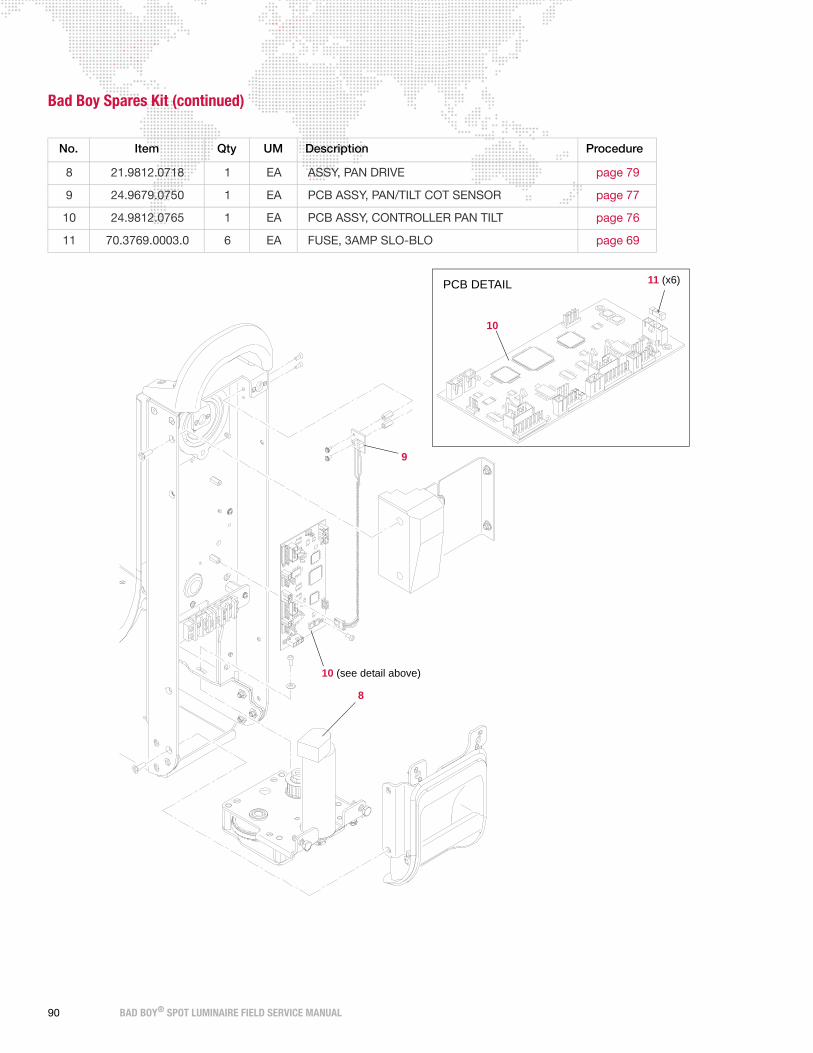
Bad Boy Spares Kit (continued)
No. Item Qty UM Description Procedure
8 21.9812.0718 1 EA ASSY, PAN DRIVE page 79
9 24.9679.0750 1 EA PCB ASSY, PAN/TILT COT SENSOR page 77
10 24.9812.0765 1 EA PCB ASSY, CONTROLLER PAN TILT page 76
11 70.3769.0003.0 6 EA FUSE, 3AMP SLO-BLO page 69
8
9
10 (see detail above)
11 (x6)PCB DETAIL
10
90 BAD BOY® SPOT LUMINAIRE FIELD SERVICE MANUAL

Bad Boy Spares Kit (continued)
No. Item Qty UM Description Procedure
12 24.9812.0510 1 EA PCB ASSY, ZOOM SENSOR page 59
12
12
12
12
BAD BOY® SPOT LUMINAIRE FIELD SERVICE MANUAL 91

Bad Boy Spares Kit (continued)
No. Item Qty UM Description Procedure
13 12.9812.0629 1 EA RETAINER, FRONT GLASS PAINTED page 50
14 22.9812.0557 1 EA ASSY, DIFFUSER PADDLE page 55
15 24.9812.0570 1 EA PCB ASSY, DIFFUSER SENSOR page 57
16 41.9812.0628 1 EA FRONT GLASS page 50
17 70.3769.0002.0 12 EA FUSE, 2AMP SLO-BLO page 68
14
15
17
16
13
92 BAD BOY® SPOT LUMINAIRE FIELD SERVICE MANUAL
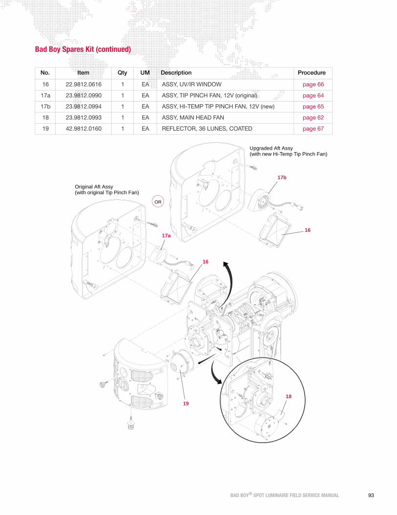
Bad Boy Spares Kit (continued)
No. Item Qty UM Description Procedure
16 22.9812.0616 1 EA ASSY, UV/IR WINDOW page 66
17a 23.9812.0990 1 EA ASSY, TIP PINCH FAN, 12V (original) page 64
17b 23.9812.0994 1 EA ASSY, HI-TEMP TIP PINCH FAN, 12V (new) page 65
18 23.9812.0993 1 EA ASSY, MAIN HEAD FAN page 62
19 42.9812.0160 1 EA REFLECTOR, 36 LUNES, COATED page 67
OR
16
17b
1819
Upgraded Aft Assy(with new Hi-Temp Tip Pinch Fan)
Original Aft Assy(with original Tip Pinch Fan)
17a
16
BAD BOY® SPOT LUMINAIRE FIELD SERVICE MANUAL 93

Notes
94 BAD BOY® SPOT LUMINAIRE FIELD SERVICE MANUAL

A.
TECHNICAL SPECIFICATIONS
+ BAD BOY SPOT LUMINAIRE
+ BAD BOY ROAD CASE
+ AC LINE CURRENT / POWER VS. VOLTAGE

Bad Boy Spot Luminaire
SOURCE: Philips MSR Gold™ 1200W FastFit Lamp.
Can be set to levels 900W, 1200W, or 1400W.
OUTPUT: 48,000 lumens
OPTICAL EFFICIENCY: 40%
REFLECTOR: Precision glass reflector with dichroic cold mirror coating.
OPERATING TEMP: -20° to 120°F (-29° to 49°C)
COOLING: Forced air.
CONTROL: Compatible with all PRG consoles and a wide variety of DMX512 and Art-Net consoles.
An internal Ethernet switch allows for daisy-chaining fixtures.
POSITIONING: Can be mounted and operated in any orientation.
SPACING: Hangs on 30 inch (762 mm) centers.
WEIGHT: 167 lbs (75.8 kg) - includes clamps and rails
ON-BOARD CONTROL: Built-in LCD display with touchscreen featuring menu system control.
ZOOM RANGE: 8:1 from narrow spot of 7° to wide flood of 56°.
ZOOM CONTROL: Four (4) groups of lenses — each independently controlled for accuracy while maintaining
focus during zoom changes
BEAM SIZE CONTROL: In addition to the zoom optics, a mechanical iris provides continuous beam size control
for both rapid changes and smooth timed beam angle changes.
EDGE CONTROL: Maintains gobo focus and allows gobo morphing.
INTENSITY: Full-field dimming from 0 to 100% with accurate slow-speed control and fast bumps.
STROBE: Servo-powered, lightning fast strobe.
FROST: Variable frost for smooth diffusion.
COLOR: Standard Version - Quantum Color® system featuring four (4) color wheels with seven
discrete colors on each wheel: one (1) designer wheel with user-changeable color filters
and three (3) fixed color wheels organized into Cyan, Magenta, and Yellow (CYM).
CMY Version - CMY color system featuring three (3) cross-fading color wheels (Cyan,
Magenta, and Yellow), plus one (1) designer wheel with user-changeable color filters.
ROTATING GOBOS: Two (2) indexable, rotating gobo wheels with seven (7) gobos per wheel. Gobos are
individually calibrated so the unit will automatically index the orientation of each gobo
regardless of placement.
PAN & TILT: Three-phase, high-speed servo motors.
RANGE: Pan - 540°, Tilt - 270°
MAX VELOCITY: 4.1 seconds for 540° of pan and 3.2 seconds for 270° of tilt.
ACCURACY: 0.2° resolution.
AC INPUT: 200-240 VAC, 50/60 Hz, 15A maximum
96 BAD BOY® SPOT LUMINAIRE FIELD SERVICE MANUAL

(762 mm)30"
15.6"(396mm)
(343 mm)13.5"
39.125"(994 mm)
POSITIONING:
Can be mounted in any orientation.
SPACING:
Hangs on 30 inch (762 mm) centers.
WEIGHT:
167 lbs (75.8 kg) - includes clamps and rails
BAD BOY® SPOT LUMINAIRE FIELD SERVICE MANUAL 97

Bad Boy Road Case
EMPTY WEIGHT: 190 lbs (86.18 kg)
LOADED WEIGHT: 357 lbs (161.93 kg) - includes (1) one luminaire with clamps and rails
(766 mm)30.15"
98 BAD BOY® SPOT LUMINAIRE FIELD SERVICE MANUAL

AC Line Current / Power vs. Voltage
Notes:
+ Tested while running all motors except Intensity/Iris/Frost functions to allow ballast to remain stable at 1400W
output to lamp.
+ Under-Voltage Lock-Out (UVLO)
- Ballast UVLO = 165V/50Hz, 185V to recover
- 24VDC LVS UVLO = 75V/50Hz, 85V to recover
About UVLO
UVLO is an acronym for Under-Voltage Lock-Out.
On a SMPS (Switch-Mode Power Supply) the input power is regulated by a PWM (Pulse-Width Modulator). Input
power is held constant by the PWM at a value equal to the load power divided by the efficiency of the SMPS (usually
.85 to .95). The Bad Boy Electronic Ballast and the 24V DC LVS (Low-Voltage Supply) are both SMPS units.
In the table above, the input power for the Bad Boy stays constant at just over 1700 Watts throughout the usable
voltage range. As input voltage is reduced further, the input current rises to unacceptable levels for the wiring, the
circuit breaker, and the PWM transistor. There are fuses on the inputs of each SMPS that prevent fires in case of
shorts on the PCB or overvoltage at the input, but these could also be blown by a voltage sag that would cause the
input current to rise. Enter the UVLO. It is a dedicated electronic circuit added to the SMPS to monitor its input
voltage and shut down the PWM if leaving it on would cause damage.
Every high-power SMPS needs this circuit to prevent damage to the components, not just semi-conductors, but
current sensing resistors, too.
The UVLO is not adjustable, it is set by the manufacturer to what he considers a safe value for his selection of
components. We have chosen vendors that provide a conservative margin for a more reliable product. We also want
to prevent nuisance dropouts.
As voltage is decreased to UVLO level, the increasing current causes additional voltage drop in the supply lines. When
the UVLO activates, (shuts down the PWM) the voltage will rise again to its no-load value. To prevent on-off cycling
(slow oscillation) based on a sensitive threshold voltage being crossed by load/no-load conditions, hysteresis is
TEST VOLTS FREQ AMPS VA POWER PF
1 170 50Hz 10.27 1746 1735 0.998
2 180 50Hz 9.62 1732 1721 0.995
3 200 50Hz 8.56 1712 1713 0.994
4 200 60Hz 8.57 1714 1709 0.996
5 210 60Hz 8.16 1714 1707 0.997
6 220 50Hz 7.77 1709 1704 0.991
7 230 50Hz 7.47 1718 1708 0.998
8 240 50Hz 7.14 1714 1705 0.993
9 240 60Hz 7.16 1718 1702 0.996
10 250 50Hz 6.83 1708 1704 0.992
11 260 50Hz 6.62 1721 1701 0.989
12 270 50Hz 6.45 1742 1689 0.966
BAD BOY® SPOT LUMINAIRE FIELD SERVICE MANUAL 99

added to the UVLO circuit. The voltage must be advanced by a considerable margin before the SMPS recovers (turns
on) from an UVLO condition, thus preventing cycling.
The Ballast is rated at 200V-240V and drops out due to UVLO at 165V and recovers at 185V.
The 24V LVS is rated 100V-240V and drops out at 75V and needs 85V to recover.
In the US, we use a 120V line cord to tech a light if we don't need to strike the lamp.
Photometric Data
Refer to the charts on the following pages.
100 BAD BOY® SPOT LUMINAIRE FIELD SERVICE MANUAL

Narrow Zoom
Iris Full Open8º Full Angle
40,000 beam Lumens
Throw Dist (Ft) 20 30 50 75 100
Beam Dia. (Ft) 2.8 4.2 7.0 10.5 14.0
Illuminance (fc) 12095 5376 1935 860 484
Throw Dist (m) 5 10 20 25 30
Beam Dia. (m) 0.7 1.4 2.8 3.5 4.2
Illuminance (lux) 193520 48380 12095 7741 5376
5000000
4000000
3000000
2000000
1000000
05.04.03.02.01.00.0-1.0-2.0-3.0-4.0-5.0
Degrees
Candela
Multiply throw distance by Tn to find beam diameter.
Divide cd (candela) by distance squared to find center beam illuminance.Dist. in Ft. = foot candlesDist. in meters = lux
Tn = 0.14cd = 4,838,000
Lamp Power = 1400 Watts
BAD BOY® SPOT LUMINAIRE FIELD SERVICE MANUAL 101

Medium ZoomIris Full Open34º Full Angle
48,000 beam Lumens
Throw Dist (Ft) 20 30 50 75 100
Beam Dia. (Ft) 12.2 18.3 30.6 45.9 61.1
Illuminance (fc) 850 378 136 60 34
Throw Dist (m) 5 10 20 25 30
Beam Dia. (m) 3.1 6.1 12.2 15.3 18.3
Illuminance (lux) 13600 3400 850 544 378
Multiply throw distance by Tn to find beam diameter.
Divide cd (candela) by distance squared to find center beam illuminance.Dist. in Ft. = foot candlesDist. in meters = lux
350000
300000
250000
200000
150000
100000
50000
020.016.012.08.04.00.0-4.0-8.0-12.0-16.0-20.0
Degrees
Tn = 0.61cd = 340,000
Candela
Lamp Power = 1400 Watts
102 BAD BOY® SPOT LUMINAIRE FIELD SERVICE MANUAL

Wide Zoom
130000
120000
110000
100000
90000
80000
70000
60000
50000
40000
30000
20000
10000
030.020.010.00.0-10.0-20.0-30.0
Iris Full Open56º Full Angle
50,000 beam Lumens
Throw Dist (Ft) 20 30 50 75 100
Beam Dia. (Ft) 21.3 31.9 53.2 79.7 106.3
Illuminance (fc) 312 139 50 22 12
Throw Dist (m) 5 10 20 25 30
Beam Dia. (m) 5.3 10.6 21.3 26.6 31.9
Illuminance (lux) 5000 1250 312 200 139
Multiply throw distance by Tn to find beam diameter.
Divide cd (candela) by distance squared to find center beam illuminance.Dist. in Ft. = foot candlesDist. in meters = lux
Degrees
Tn = 1.06cd = 125,000
Candela
Lamp Power = 1400 Watts
BAD BOY® SPOT LUMINAIRE FIELD SERVICE MANUAL 103

Logarithmic Beam Illuminance Comparison
140000
120000
100000
80000
60000
40000
20000
030.020.010.00.0-10.0-20.0-30.0
8º, 34º and 56º Zoom settings.(DMX Values 00000, 30192, & 57700)
10000000
1000000
100000
30.020.010.00.0-10.0-20.0-30.0Deg.
WFOV
MFOV
NFOV
Lamp Power = 1400 Watts
Candela
140000
120000
100000
80000
60000
40000
20000
030.020.010.00.0-10.0-20.0-30.0
140000
120000
100000
80000
60000
40000
20000
030.020.010.00.0-10.0-20.0-30.0
140000
120000
100000
80000
60000
40000
20000
-30.0 -20.0 -10.0 0.0 10.0 20.0 30.0deg.
Operation at Reduced Power
56º Zoom
1400W = 50,000 lumens1200W = 43,000 lumens1100W = 40,000 lumens
Candela
104 BAD BOY® SPOT LUMINAIRE FIELD SERVICE MANUAL

BAD BOY® SPOT LUMINAIRE FIELD SERVICE MANUAL 105
WIRING DIAGRAMS
Bad Boy Luminaire Wiring Diagram
RJ-45
ConnectorLegend
Mother Board PCBBad Boy Wheel
R1 Sensors
Butt Splice
#6 Ring
#10 Ring
PicoSPOX
MolexSL
AMPLatch
MolexMFJ
MTA156
MTA100
3 Yellow
4 Magenta5 R1 Wheel
6 R1 Index
7 Gnd
2 Strobe
1 +5V
J35
4 Des Col
7 Gnd
6 R2 Index
5 R2 Wheel
R2 SensorsJ50
2 Dimmer
3 Cyan
1 +5V
J49
3 Gnd
2 Sense
1 +12V
Pinch Fan
Gnd
+24V
J41
J40Main Fan
4 Gnd
2 +12V
3 Sense
Iris FanJ27
Iris-Gobo FanJ38
2 V
3 U
1 W
3
4
Sensor
J51
1
2
Red 26N/C
Blk 26Wht 26
25-9812-0988
Diffuser
Gobo12VDC
Fan 1
23-9812-0989-02
J37
Sense 3Blk 26Gnd 4
N/C
Yel 26
+24V 1
+12V 2 Red 26
J36
23-9812-0989-01
Yel 26Red 26
Blk 26
N/C
GoboFan 2
12VDC
J13
Gnd 3
Sense 2
+5V 1
Iris Sensor
24-9812-0650J48
24-
98
12-
0650
24-9812-0649
J1
Dimmer2
J3
J2 1
J19
3
J18
2
J42
J46 1
J30
3
J32
J17
Strobe21 3
2 13
3J25 1J21 2
R2 Wheel
J22J24
J44
R1 Wheel J20
J31R2 Index
J23R1 Index
3
J47
1J8 2
J9
J43
Magenta
J6
J7
J16
2
CyanJ5 1
J12
J4
3
J15
J52
Iris2J11 13
J54
J10
321
J45Designer
J14
Yellow1 2 3
J53Diffusser
DimmerMotor Assy
Red
20
Blk
20
Wht
20
Grn
26
Yel
26
Brn
26
Gry
26
Blu
26
1 23-9812-0669-04
25-9812-0965
Wht 22x12LampRelay
To
LampTo
From
RelayFrom
Butt Splice10-12 AWG
24-9679-1275
Arc Ignitor PCB
25-9812-0964
BulkheadGnd Screw
Rear
1200 Fast FitMSR Gold
Lamp SocketGnd Screw
25-9812-0959ArcLamp
Philips #
G
Blk 12
Wht 12
25-9812-0963
A B
9
7Blk 22x12
Wht 22x12 6
4 Blk 22x12
AXISPAN
25-9812-0952
25-9812-0951
PowerConAC Input
AC Neut
AC Gnd
AC Line
Wht 14N
Grn/Yel 14G
Blk 14L
69-3180-1400-0
BallastControl
ManualOn/Off
Gnd 6
Power Hi/Lo 3
Lamp Status 4
Lamp On/Off 5
Power Adjust 2
Gnd 1
Brn 24
Orn 24Gry 24
Brn 24G/Y 24
Lamp On/Off 1
Lamp On/Off 2
EMI Filter PCB
Grn/Yel 14
Arc Ballast1400W
25-9812-0955Wht 14
Blk 14
25-9812-0956
Blk 14
Wht 14
Grn/Yel 14AC Gnd
AC Neut
AC LineAC Line
AC Neut
L
N
GN
L
1 2 3 4 5 6 7 8+24V DC Gnd
G L NACGnd Line
ACNeutAC
ChassisGnd Screw 1
G
5J2
5J1
G L NACGnd Line
ACNeutAC
25-9812-0954
2Ignitor 2 Ignitor 1
1
(BLK) (WHT)
1
2
Ballast
BlockTerminal
23-9812-0995-02
Adjust Status 4Orn 24
N/C 7
Gnd 6
Lamp On/Off 5
Backup
Ethernet
Can - 2Wht 24
G/Y 24Brn 24
Gry 24
Gnd 1
Power Adjust 2
N/C 3
Ballast Control
J1
Blk 24Gnd 3
J4Red 24
CAN Bus
Can + 1
J10
Blk 26Blk 26Red 26
Red 26+3.7V 1
Gnd 3
Gnd 2
+3.7V 4
Battery
J11
RJ-45 Port B
J12
RJ-45
4 Iso Gnd
3 DMX +
J14
2 DMX -
1 Chas Gnd
DMX Input
J131 LED
Gnd
LED2
3
InputDMX
LEDR/G
Ethernet Ports
DMXPCB
Cat 5
Cat 5
Orn 22Grn 22
Brn 22G/Y 22
Wht 24Blk 24
2
3
J3
Comm
J5
24-9812-0871
PCBDisplayPanel
RibbonCable
Ribbon CableDisplay
1
4
EthernetPort A
25-9812-0961
25-9812-0961
Port 2
Red
18
Blk
18
Blk
18
Red
18
Gnd
Gnd
3 4 DC
+24
V
+24
V
J7 1 2
25-9812-0960
ThruDMX
24-9812-0842 Ballast24VDC
Fan 2
Wht 26
23-9812-0987-03Blk 26
RIGHT EXT 5"Red 26
Gnd 2
3
+24V 1
J3
2 Fail
4 N/C3 Gnd
1 +24V
Fan 2Output
CN1
Low Voltage Supply69-3131-0001-0
+24V/600W
Input
YOKE
BlockTerminal
B A
2
1
4
3
6
5
Lens Group 2
3
Group 43
J4
Red 22x2Blk 22x2Blk 22x2
Red 22x2
J17
J9 13 2 21
24-9812-0511Controller PCB
Zoom
Lens Group 3
Lens Group 1
J7 1 32
J13
21
J15
EOTLG2
EOTLG3
EOTLG4
+12V 2
+24V 1
Sense 3
Gnd 4
J26
24
-98
12-
065
0
J33
J34
3 N/C
25-9812-0966-01
4 Adjust Status5 Lamp On/Off
1 Gnd2 Power Adjust
25-9812-0966-02
J10
J18
J12
J14
J11
J8
J16
25-9812-0969
Red 22x4
Red 22x4
Red 22x4
25-9812-0969
Blk 22x4
Blk 22x4
Blk 22x4
25-9812-0968
25-9812-0980-01
Red 22x10
Red 22x10
Red 22x8
Blk 22x10
Blk 22x8
Blk 22x10
Red 22x2
Red 22x2
Blk 22x2
Blk 22x2
Red 22x2
Red 22x2
Blk 22x2
Blk 22x2Blk 22x2
Red 22x2
Red 24
Blk 24Wht 242
3
1
25-9812-0980-02
+12V 2
Gnd 4
Sense 3
+24V 1
Fan
12VDCTip Pinch
Blk 24
Red 24Whtl 24
Iris12VDC
Fan
Yel 26Red 26
Blk 26
23-9812-0991
23-9812-0994
23-9812-0992
Iris-GoboFan
12VDC
23-9812-0993
Main12VDC
Fan
Wht 26Red 26
Blk 26
25-9812-0983
SensorPCB
Wheel
Gry 24Blk 24
Red 24
Wht 24
Brn 24Yel 24Vio 24
24-9812-0658
R2
J1
Red 24
24-9812-0655
PCB
WheelSensor
R1
Gry 24Blk 24
Brn 24
Wht 24Vio 24Yel 24
J1
25-9812-0983
24-9812-0570
DiffuserSensor PCBJ1
1 +5V
3 Gnd
2 Sense
BusCAN
J29
J28
1 Red 24
2 Wht 24
3 Blk 24
J3
BusCAN
Max Spd 5
Spd Cntl 4
Gnd 2
J39
+24V 1
Tach 3
Gobo Fan 1
Gobo Fan 2
25-9812-0982
Wht 26Blk 26
Red 26
24-9812-0653
IrisSensor PCBJ1
1 +5V
3 Gnd
2 Sense
26x325-9812-0984
26x326x326x3
SensorsEOT
LG2
LG1
J1
LG3
LG4
J2
25-9812-095825-9812-0957
YokeGnd Stud
G
Gnd StudHead
G
TILTAXIS
AXISPAN
25-9812-0962
25-9812-097525-9812-0977Orn 22
BulkheadMounting
Rear
25-9812-0976Red 22
25-9812-0980-03
25
-98
12-0
980
-04
25
-98
12-
097
0
25-9812-0973
25
-98
12
-09
70
25-9812-0970
1
2
3
4
5
6
25-9812-0996
Jumper
25-9812-0981
TYPICAL
23-9812-0669-03
23-9812-0669-02
23-9812-0668-01
TYPICAL25-9812-0985-02
23-9812-0668-03
G
Gnd Screw 2Chassis
Blk 12
Wht 12
Red 22x2
Red 22x2
Blk 22x2
Blk 22x2
Can +
Can -
Gnd
2 Wht 24
3 Blk 24
1 Red 24
HOTSwitch G
J1
J2
J3
J4
Relay23-9812-3327
HOT
Screw
Fan 1
24VDCBallast
LEFT EXT 8"
23-9812-0987-02
Gnd 2
+24V 1
OutputFan 1
Red 26
Blk 26Wht 26
3
J2
4 N/C
1 +24V
3 Gnd2 Fail
23-9812-0987-01
23-9812-0987-01
DMX LED
HEAD
Orn 28Red 20
Red 26 1
Blu 26 2 Brake
J15
Tilt
J9J14
Gry 26
Yel 26
Brn 26
Grn 26
Blu 26
Wht 20
Blk 20
Enc
oder
s
Yel/Wht 28
Blue 28
Yel 28
Orn/Wht 28
Blu/Wht 28
Blk 28
Red 28
2
1
3
21-9812-0719Mechanism
Tilt Drive
Tilt Motor
J13
Blk
26
3
Wht
26
2
Red
26
1
J5
Tilt COTSensor
Pan/TiltController PCB
24-9812-0773
BusJ3
J2
CAN
RibbonCable
25
-98
12
-09
86-0
2
J16
J7
J12
J11
BrakePan
J6
J10J8
32
1
Sensor PCB25-9812-0979
Sen
se
Gnd
+5
V
Tilt COT
Pan Motor
YOKE
LVS Status
J61 Gnd
2 DC OK
3 N/C25-9812-0967
G/Y 24Gry 24
1 I Monitor
5 Remote On
4 Power Good
2 I Share
3 Control Gnd
6 V Sense -
7 V Sense +
LinesControl
LVS
G/Y 24
Gry 24
CN3
Port 1
Controller PCB24-9812-0870
Main
25-9812-0953
73-7200-0006-0
10
9
8
7
6
5
4
3
1
2
1
2
3
4
5
N/C
4
Gnd
+24V
+24V
Gnd
4
1
3
2
+24V
+24V
Gnd
Gnd
4
3
2
1
Red 24 1
Wht 24 2
Blk 24 3
3
2
1
Blk
24
Wht
24
Red
24
2
1
3
1 N/C
1 N/C
4 Gnd
3 Sense
2 +12V
Yel 26Red 26
Blk 26
123
3 2 1 Motor
R2 IndexStepper
44-5036-0001
Yel
26
Red
26
Blu
26
1 11
2010
25-9812-0973
BusCAN
23-9812-0669-09
Lens Group 4
CableRibbon
TYPICAL
Motor Assy
Blu
26
Gry
26
Brn
26
Yel
26
Grn
26
Red
20
Wht
20
Blk
20
Blk
26
Wht
26
LG1EOT
J1
1 2 3
Red
26
24-9812-0510TYPICAL
RibbonCable
.187 Faston
.250 Faston
(Not Used)Use J40
Main Fan
Enc
oder
s
25
-98
12
-09
86-0
1
1 Red 26
2 Blu 26
Yel/Wht 28
Orn/Wht 28
Blu/Wht 28
Blk 28
Red 28
Yel 28
Blue 28
Orn 28
21-9812-0718
Pan DriveMechanism
RibbonCable
Red 20
Blk 20
Grn 26
Wht 20
Gry 26
Brn 26
Blu 26
Yel 26
10
4
1
3
2
7
6
5
9
8
2
5
3
4
1
23-9812-0995-01
BatteryBackup
Pack
2
Red 24Orn 24
Blk 24
1
Blk 24Red 24
2 (Gnd)(+3.7V) 1
Wake Switch
14
2
15
1
EncoderPosition Position
Encoder
1
15
AXISTILT
2
14
YOKECHASSIS
HEADYOKECHASSIS YOKE
25-9812-0997

Bad Boy® Spot Luminaire Field Service Manual
Version as of: June 23, 2011
PRG part number: 02.9812.0005 E

Production Resource Group
Dallas Office
8617 Ambassador Row, Suite 120
Dallas, Texas 75247
www.prg.com