backscatter and extinction measurements in cloud and drizzle at co_2 laser wavelengths
TRANSCRIPT

Backscatter and extinction measurements in cloud anddrizzle at CO2 laser wavelengths
S. G. Jennings
The backscatter and extinction of laboratory generated cloud and drizzle sized drops have been measured atCO2 laser wavelengths (predominately at X = 1 0.591,um). Measurements of volume backscatter coefficient aband volume extinction coefficient e for laboratory cloud of predominantly <20-gm radius droplets aredependent on the form of the size distribution in agreement with numerical prediction. For drops of 520 gmat X = 10.591 Am the relation between aee and ab has the appealingly simple size distribution independent formof 0ee!b = 8rG
(n-1)2 + k2(n+ 1)2 +k2
is the asymptotic value of the backscatter gain, where n and k are the real and imaginary indices of refraction.The linear relation is in good agreement with extinction and backscatter measurements made on laboratorygenerated drizzle sized drops (r > 20 gim). This suggests that the extinction coefficient at CO2 laserwavelengths could be inferred from lidar backscatter return signals without requiring knowledge of the sizedistribution for drizzle and spherical precipitation sized water drops.
1. Introduction
Considerable attention has been given by scientiststo seeking a possible relationship between the volumebackscatter coefficient and extinction coefficient (orvisibility) for atmospheric cloud. The use of the lidarhas further stimulated interest in this quest. For ex-ample, knowledge of the backscatter-to-extinction ra-tio can be used to infer extinction profiles from lidarbackscatter return signals, if the form of the dropletsize distribution is spatially invariant.'
Most of the effort to date has been expended onnumerical calculations of volume backscatter and ex-tinction coefficients at visible and near-IR wave-lengths based on model and measured cloud size distri-butions.2 -6 Backscatter and transmission (visibility)field measurements for atmospheric conditions rang-ing from relatively clear air to fog and fog and drizzlehave been reported for the visible wavelength range.7'8The extinction and backscatter of visible laser radia-tion in laboratory generated cloud droplet distribu-tions have been measured.5'9 Their measurementsshow a linear dependence of backscatter on extinctionin good agreement with prediction.5
The numerical calculations5 using Mie theory of ex-tinction and backscatter at the C02 laser wavelength X
The author is with University College Galway, Department ofExperimental Physics, Galway, Ireland.
Received 11 January 1986.0003-6935/86/152499-07$02.00/0.© 1986 Optical Society of America.
= 10.6 gm for 156 cloud droplet size distributionsmeasured in the major cloud types show considerablevariation (up to a factor of 7) in calculated extinctionfor a particular backscatter coefficient. However, acloser examination of their numerical results revealsan upper bound constant value for the extinction-to-backscatter ratio of -3.5 X 10³ sr for the cloud typeswhich contain a wide spectrum of drop size: cumulo-nimbus; altostratus; nimbostratus; and orographic.In addition Derr6 shows through numerical calculationat X = 10.6 ,um that the extinction-to-backscatter ratiois essentially constant for an 15 -Am radius.
Despite the increasing use of CO2 lasers for remotesensing of the atmosphere, backscatter and extinctionmeasurements at mid-IR wavelengths are sparse. Ef-forts to extract attenuation from a C02 lidar returnsignal have to date been largely statistical in nature.Some of the principal recommendations which result-ed from a workshop on global aerosols, compiled byHall,'0 included the necessity of C02 backscatter andextinction measurements-both requiring experimen-tal and theoretical work. Backscatter measure-ments 1 normalized to X = 10.591 m for submicro-meter sulfuric acid and ammonium sulfate aerosols arein reasonably good agreement with theory.
In this paper, measurements of backscatter and ex-tinction coefficient at C02 laser wavelengths (primari-ly at the P20 line, X = 10.591 ,m) for water drop cloudsare presented. Two distinctly different drop size re-gimes are studied, one which covers the range normallyencompassed by natural cloud droplets [1 < radius (r)< 20 um] and the other representative of mist or drizzlesized drops (20 r 150 m). A size distribution-dependent relation, expected to be valid for the small-er size regime, is derived between backscatter and
1 August 1986 / Vol. 25, No. 15 / APPLIED OPTICS 2499

extinction at X = 10.591 m using modified gammadistribution functions representative of naturall2- 14
and artificial clouds. Laboratory measurements arewithin a factor of -2 of this prediction. For the largedrop size regime (r s 20 Am) a single value for the ratioof extinction to backscatter (independent of drop sizedistribution) for water drops of radius s2 0-Am radiusis predicted for X = 10.591 Am. Backscatter and ex-tinction measurements for larger sized water drops (rs 20 Mm) give reasonably good agreement (within afactor of 2) with this single value. So measurements ofthe small and large drops are within a factor of 2 ofpredicted backscatter-to-extinction ratios.
11. Extinction and Backscatter in Cloud
The transmission of a monochromatic laser beamthrough a cloud is derived from the Lambert-Bouguerlaw. The extinction coefficient are (m-1) is determinedfrom the measurement of the transmitted signal I aftertraversal through the cloud of path length L:
I = Io exp(-aeoL), (1)
where Io is the initial intensity of the laser radiation inthe absence of cloud.
The volume extinction and backscatter coefficientsae and Ub of a polydispersion of spherical cloud dropletscharacterized by a size distribution n(r) and refractiveindex m are given by
ae = J 7rr2 Qen(r)dr,
Oab = ' J r 2Gn(r)dr,
a0F-
0
0zw
0
0z
UL
10 A 15
SIZE PARAMETER, X
25
Fig. 1. Efficiency factor for extinction Qe vs droplet size parameterx for water at wavelength X = 10.591 gm (index of refraction m =1.179-0.0718i). The efficiency factor is approximated by a straight
line Qe = cx for x • xm.
C9
Z0.03C,3cc
W 0.02
0 0.01n
0
(2)
(3)
where Qe(m,x) is the Mie efficiency factor for extinc-tion for a particle with refractive index m and sizeparameter x = 2rr/X, and G(m,x) is the backscattergain defined as 47r times the ratio of the backscatterdifferential cross section to the geometric area.
The efficiency factor for extinction (or normalizedextinction cross section) Qe(m,x) is plotted in Fig. 1 as afunction of x for water droplets at wavelength X =10.591 Mm using the index of refraction of water givenby Hale and Querry.'5 Qe(m,x) is reasonably well ap-proximated16 by a straight line with slope c(X) for 0 < x< xm up to maximum size parameter xm, which is of theform
Qe(m'x) = c()x. (4)
An approximate value for the coefficient c(X) at X =10.591 um from Fig. 1 is c = 0.28 for xm = 12.
The backscatter gain (or normalized backscattercross section) G(m,x) is plotted in Fig. 2(a) as a func-tion of x for water droplets at wavelength X = 10.591Am, showing the familiar damped oscillating patternwith period Ax 1.1-1.2. If one can assume that thecloud droplet polydispersions used here possess fairlyuniform number concentration over corresponding ra-dius intervals (r 2 Am), the oscillatory componentevident in the exact Mie results can be averaged bymeans of the approximation
0.04CDz( 0.03
0ci,r 0.02
U)0.01
Q
0
D Iu ID Zu
SIZE PARAMETER, X
2 3 4 5 6
SIZE PARAMETER, X
,o
7 8 9
Fig. 2. (a) Mie calculations of the backscatter gain G(m,x) vs sizeparameter x for water droplets at wavelength X = 10.591 gm (index ofrefraction m = 1.179-0.0718i). (b) Curve fit to the Mie gain G(x,m)
= g(X)x2/3 exp (-x/3); Eq. (5) is shown.
G(m,x) = g(X)x2/3 exp(-x/3), (5)
where g(X) is a function of wavelength and possessesthe 2.577 X 10⁻² value at X = 10.591 ,m. This approxi-mate expression is shown compared with the exact Mie re-sult in Fig. 2(b). It should be noted that this expressionhas the incorrect asymptotic limit for large x(x s 9).
Use of these approximations for the Mie efficiencyfactor for extinction (4) and backscatter gain (5) inEqs. (2) and (3) leads to the cloud extinction coeffi-cient being related to the backscatter coefficient by
ee 47rck'/3
Ub g
f r3n(r)drf r813 exp(-kr/3)n(r)dr
where k is the wave number.The modified gamma distribution function of form
2500 APPLIED OPTICS / Vol. 25, No. 15 / 1 August 1986
7 I F I I I
(a)A = 10.591 um
I I I I I I I I
G(X) = 9 X213 exp(-X/3) (b)
A = 10.591 um
- ~~~~~~~G(MIE)
/~~~~~~
u
o 1

Table I. Extinction-to-Backscatter Ratio Values of X = 10.591 Am forWater Drops Having a Modified Gamma Size Distribution form
Characterized by Parameters a and b
a Extinction-to-backscatter ratiob \ 1 2 3
1 434 557 7070.833 537 713 9330.667 720 1000 1374
0!RIxcl:x
0CO0
C00zI'
20 30DROPLET RADIUS (m)
Fig. 3. Mie calculation of the extinction-to-backscatter ratio forwater droplets vs droplet radius at wavelength A = 10.591gum (index
of refraction m = 1.179-0.0718i).
n(r) = ara exp(-br) (7)
represents reasonably well sized distribution spectrafor natural cloud'2-'4 and laboratory cloud (see Sec.IV). Accordingly the modified gamma distribution is,bh-an -in oercon -ln-A Aarhl~ncrasubstuull to oluf Eq. ) LntUUU E.Ut(lurull
Substitution of Eq. (7) into Eq. (6) resul
ae 47
ab
ck" 3 f r.+3 exp(-br)dr
g f r.+8/3 exp[- (b + k dr
which reduces toee 47rck"/3 (b + k/3)a+1 /3
eab g b.+4
3,+3(a + 3)(a + 2)(a + 1)ar(a)[2.5.8.. (3a + 8)]r(2/3)
where the gamma function r(2/3) = 1.354culated values of extinction-to-backscatterange of a and b values representative of laboratory cloud vary from 434 to 1374 as tTable I. Thus the relationship between and extinction is dependent on the form ofsize distribution at X = 10.591 um for dropltions typical of cloud and fog.
Ill. Backscatter and Extinction for Large Wawith radii 20 lum, at X = 10.591 m
Here we consider cloud and drizzle-sizedsize parameter x 12 (r 20 m at X =:The efficiency factor for extinction Qe apasymtotically for an absorbing droplet aser.17 [Qe decreases from 2.56 at x = 12 to 2.(r = 118 m).] It can be seen from Fig.
AMPLIFIER GAUGE
PRE-AMPLIFIER ATOMZNG COPRESSORJ+ 3 A T O M > 3~~~MIZ
HgCdTeDETECTORX
| TUNABL~E F .J . . ,|Ji A........I...::-.:.:. .. .... .. R.ETECTOR.
CHOPPER CLOUD HOUSING
MIRROR
SPECTRUM ... ......;ANALYSER
Fig. 4. Schematic diagram of the experimental arrangement.
backscatter gain G oscillates with a period of Ax 1.15about an asymtotically decreasing value approachingthe geometrical limit which equals the reflectivity R ofthe material at normal incidence'8 where
(n - 1)2 + k 2
R =(n + 1)2 + k 2
(10)
where n and k are the real and imaginary indices ofrefraction. R equals 0.0078255 for water (m = 1.179-0.0718i) at X = 10.591 gm. [The calculated Mie valuefor G(m,x) at X = 10.591 gm for x = 150 is equal to0.0078258.]
The asymtotic values of Qe and G in Eqs. (2) and (3)lead to an appealingly simple form independent of sizedistribution
-= 4 Qe_U= 41r- = 3.21 X 03 sr.eb G
(11)
.Pt;LUUL. Numerical calculations of extinction-to-backscatterts in ratio at X = 10.591,um for water droplets up to 50-Mm
(8) radius (size parameter = 30) plotted in Fig. 3 show the() 'extinction-to-backscatter ratio oscillating with period-
icity Ax 1.10 (Ar 1.86 Arm) about a relativelyconstant value of 3.40 X 10³ sr, some 6% larger than theasymtotic limit of Eq. (11). From an examination ofFigs. 2(a) and 3 it was considered justifiable to use theasymtotic value of backscatter gain for a drop sizeparameter as small as 12. The use of the asymtotic
(9) value of 2 for Qe tends to underestimate the elb ratioby -6-7% over the size parameter range of 12-70.
1179. Cal- IV Experimental Measurement of Backscatterr ratio for a Coefficient and Extinction Coefficient at CO2 Lasernatural and Wavelengthsabulated inbackscatter A. Experimental Apparatus and Techniquesthe droplet The apparatus used to measure backscatter and ex-et distribu- tinction in water cloud is shown schematically in Fig. 4.
The measurements were restricted to laboratory simu-lation of cloud and drizzle because of the difficulty in
ter Drops making natural atmospheric measurements. A 1-M3
chamber of path length L = 1 m constructed of water-drops with proof plywood was used for all measurements. Cham-
[0.591 m). ber saturation and cloud stability were maintained,proaches 2 through the use of matte black absorbing cloth materi-x gets larg- al lining the chamber walls. The optical arrangement10 at x = 70 used in the extinction and backscatter coefficient mea-2 that the surements consists of a tunable vertically polarized
1 August 1986 / Vol. 25, No. 15 / APPLIED OPTICS 2501

CO2 laser source (Sylvania model 941S) with wave-lengths available over the 10.2-10.7-Mm wavelengthrange. The CO2 laser transmission path is made coin-cident with a visible (0.6328-Mim) He-Ne laser trans-mission path. Alignment is accomplished with alumi-nized mirrors which are mounted on micrometer-controlled translational and rotational stages. Aportion of the CO2 laser beam is reflected by a ZnSewindow for a laser reference signal. The main beamenters the cloud chamber of path length L through a 5-mm diam window and exits through a small aperture(few millimeters diameter) into a second detector.This arrangement also allowed for the extraction ofbackscattered light from the cloud droplets in thechamber. The main beam and reference detectors(Laser Precision Corp. models RkP-545 and Rk-5100)consist of a pyroelectric laser probe together with asynchronous radiometer readout. The synchronousratiometer readout model Rk-5200 is used for the out-put of the ratio of the main beam and reference signals.The detectors have negligible drift (10-6 W cm-2after warmup) compared with typical radiance levelsmonitored by the detectors (of the order of 1 W cm-2).The radiation wavelength is monitored precisely witha spectrum analyzer (Optical Engineering, Inc., model16-A CO2 laser spectrum analyzer).
An Infrared Associates, Inc., mercury cadmium tel-luride (HgCdTe) liquid nitrogen cooled 8-13-,m radi-ation photoconductive detector (model HCT-90) wasused for measuring the backscattered radiation. In anattempt to make simultaneous backscatter and extinc-tion measurements a technique successfully used byPinnick et al. 5 at visible wavelengths was tried where-by a central hole drilled through a metallized mirrorsurface admits the laser beam through the cloud cham-ber and at the same time intercepts the backscatteredradiation onto the HgCdTe detector. However, it wasnot possible to use this technique because of the occur-rence of directly reflected radiation from the internalwalls of the hole onto the sensitive detector (due torelatively large CO2 beam diameter, -5 mm) therebysaturating the detector. Accordingly, the detector wasplaced close to the CO2 laser axis in the backwarddirection at a distance not more than 5.9 cm from theaxial direction, thus subtending an angle C- 177.4° withthe forward direction at the chamber center. TheHgCdTe detector was mounted on an x-y translationstage with vertical height adjustment.
The evacuated detector possessed a metal Dewarassembly which contained the necessary liquid nitro-gen for cooling the detector. The HCT-90 detectorhad a sensing area of 1 mm2. The signal from thedetector was fed into a Infrared Associates modelPPA-15-1 preamplifier, then into the input of a EG&GBrookdeal model 9501 lock-in amplifier. A EG&GBrookdeal model 9479 light chopper operating nor-mally at 1000 Hz served as reference to the lock-inamplifier. The amplifier output from the lock-in am-plifier was recorded on a Philips model PM8100 chartrecorder. Precautions were taken to reduce stray IRlaser radiation from entering the detector during ex-
perimental runs. The detector aperture on the pyro-electric probe RkP-545 was maintained at 3 mm tominimize forward-scattering corrections to the trans-mission signal. Due to the necessarily high sensitivityof the HgCdTe detector, it was not possible to makesimultaneous measurement of extinction and back-scatter in the chamber cloud. (This is because thereflected signal from the walls of the pyroelectric de-tector probe at the exit of the chamber greatly exceed-ed the true backscatter signal from the cloud.) Thiswas not deemed to be a critical constraint on the mea-surements because of the stable conditions of thecloud. The backscatter output signal from the lock-inamplifier was calibrated by directing a range of knownlow CO2 laser radiation signals onto the HgCdTe de-tector. The low-level CO2 laser radiation signals weremonitored on the model Rk 5100 radiometer operatingin synchronization with a Laser Precision Corp. modelCTX-32 external chopper. The absolute value of theCO2 laser radiation (in watts) was determined from thepyroelectric RkP-545 probe. The pyroelectric detec-tor was calibrated by means of an Electro-Optical In-dustries, Inc. blackbody source model WS 153 of 2.54-cm (1-in.) conical cavity with temperature controllerproviding a temperature range from 50 to 1000°C.The backscatter coefficient o-b (m-1 sr-') is derivedfrom the backscatter signal through use of the expres-sion
b+L AIB I ab b+ )2 exp(-2e~l)dl, (12)
where IB is the measured backscatter signal (in watts);I, is the absolute value of the CO2 laser radia-
tion (in watts);ab is the backscatter coefficient (m-' sr-');A is the detector area; andb is the path length between the detector and
chamber entrance.The lowest measurable backscatter signals in cloud
and drizzle were of the order of 0.1 nW mm-2 .Water droplet clouds were normally produced by a
pair of Hankscraft spinning disk humidifiers diagonal-ly positioned within the cloud chamber. The clouddroplet size distribution was determined by a particlemeasuring system (PMS) classical scattering aerosolspectrometer probe (CSASP) which can sense waterdroplets with radii from 0.23 to 14 Mtm.'9 A modifiedtwo-stage inpactor20 mounted in a wind tunnel alloweddroplet sizes >14-Mm radius (upper limit of the parti-cle scattering counter) to be measured. Averagedmeasured droplet size distribution in histogram formgenerated using the pair of spinning disk humidifiergenerators is shown in Fig. 5. Narrower droplet spec-tra predominately in the radius range of 0.3 to -9,Mmwere generated by a DeVilbiss model 65 ultrasonicnebulizer operating at a frequency of 1.35 MHz.
Drizzle sized drops in the laboratory with radiusranging from 20 to -150,um were produced by a pair offine spray atomizing nozzles (type 1/4 LN4, 1/4 LN6manufactured by Spraying Systems Co., Wheaton, IL60187).
2502 APPLIED OPTICS / Vol. 25, No. 15 / 1 August 1986
I I X I 1 l5 10 15 20 25 30 35
DROPLET RADIUS (um)
Fig. 5. Averaged laboratory cloud size distribution histogram fromthe Hankscraft spinning disk generators. The measured size distri-bution has been fitted with a gamma function [Eq. (7)] with parame-ters a = 3, b = 0.75. Larger drop size categories indicated by-*-
were measured using a modified two-stage impactor.20
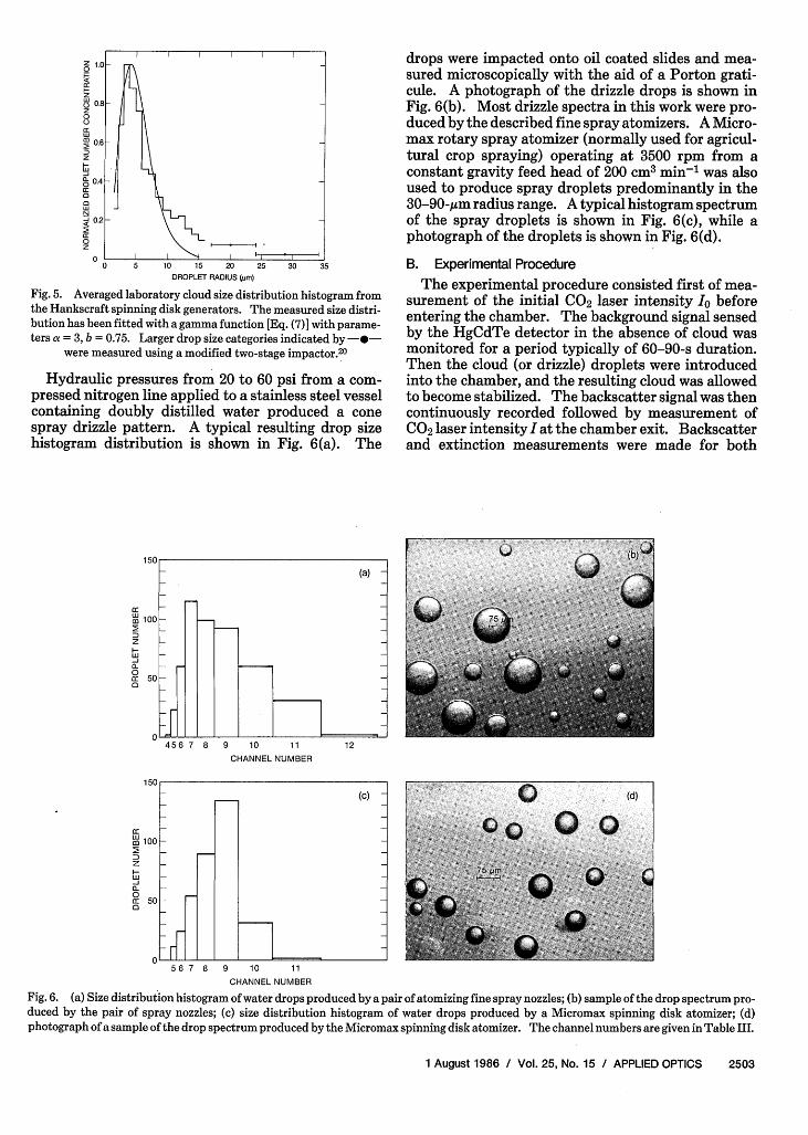
Hydraulic pressures from 20 to 60 psi from a com-pressed nitrogen line applied to a stainless steel vesselcontaining doubly distilled water produced a conespray drizzle pattern. A typical resulting drop sizehistogram distribution is shown in Fig. 6(a). The
150
(a) -
n 100 l
z-
0a50 F
456 7 8 9 10 11
CHANNEL NUMBER
12
drops were impacted onto oil coated slides and mea-sured microscopically with the aid of a Porton grati-cule. A photograph of the drizzle drops is shown inFig. 6(b). Most drizzle spectra in this work were pro-duced by the described fine spray atomizers. A Micro-max rotary spray atomizer (normally used for agricul-tural crop spraying) operating at 3500 rpm from aconstant gravity feed head of 200 cm3 min' was alsoused to produce spray droplets predominantly in the30-9 0-;im radius range. A typical histogram spectrumof the spray droplets is shown in Fig. 6(c), while aphotograph of the droplets is shown in Fig. 6(d).
B. Experimental Procedure
The experimental procedure consisted first of mea-surement of the initial CO2 laser intensity Io beforeentering the chamber. The background signal sensedby the HgCdTe detector in the absence of cloud wasmonitored for a period typically of 60-90-s duration.Then the cloud (or drizzle) droplets were introducedinto the chamber, and the resulting cloud was allowedto become stabilized. The backscatter signal was thencontinuously recorded followed by measurement ofCO2 laser intensity I at the chamber exit. Backscatterand extinction measurements were made for both
m 100
z
00a 50a
56 7 8 9 10 11
CHANNEL NUMBER
Fig. 6. (a) Size distribution histogram of water drops produced by a pair of atomizing fine spray nozzles; (b) sample of the drop spectrum pro-duced by the pair of spray nozzles; (c) size distribution histogram of water drops produced by a Micromax spinning disk atomizer; (d)photograph of a sample of the drop spectrum produced by the Micromax spinning disk atomizer. The channel numbers are given in Table III.
1 August 1986 / Vol. 25, No. 15 / APPLIED OPTICS 2503

2
1i0zE
Ca
0z00
F-0
5
2
in-,2 5 10-3 2
BACKSCATTER COEFFICIENT (m-' sr-')5
Fig. 7. Measured values of backscatter and extinction coefficientfor laboratory water cloud at wavelength A = 10.591 gm. Hankscraftspinning disk steady-state cloud values, 0; Hankscraft spinning diskdecay cloud values, 0; Hankscraft spinning disk combined withultrasonic nebulizer steady-state values, A; Hankscraft spinningdisk combined with ultrasonic nebulizer decay values, ,. Measure-ments made at A = 10.247 im: Hankscraft spinning disk steady-state values, ; Hankscraft spinning disk decay values, . Twosolid lines representing extinction-to-backscatter ratios of 300 to 600
sr are also shown.
2
-'E 10°5
I-
, 5a00
0F_
2
10'2 5 10-
42 5
BACKSCATTER COEFFICIENT (m-1
sr-')
10-3
Fig. 8. Measured values of backscatter and extinction coefficientfor larger sized water drops at wavelength X = 10.591 gum. Steady-statemeasurements, *;decaymeasurements, o. All measurementswere made with drops produced by atomizer spray nozzles except forthose using a rotary spinning disk device indicated by A. The solidline represents the asymtotic ratio of extinction to backscatter, Eq.
(11).
steady-state cloud conditions and some cloud decayevents. Signal-to-noise ratios of between 14 and 22 onaverage prevailed for the backscatter measurements incloud. However, for the drizzle sized droplets the sig-nal-to-noise signal was considerably lower (between1.2 and 1.33) due to the characteristically lower back-scatter signal from the drizzle drops.
C. Backscatter and Extinction Measurements
Measurements of backscatter coefficient and extinc-tion coefficient in laboratory cloud at wavelength X =10.591 Mm are presented in Fig. 7. Measured valuestaken in steady-state cloud conditions using a pair ofspinning disk humidifiers are indicated by the soliddots . The experimental points 0 represent mea-
surements of backscatter and extinction coefficientsmade at 5-s intervals during cloud decay. Steady-state measurements using a combination of two spin-ning disk devices together with an ultrasonic nebulizerare indicated by the points A in Fig. 7, while decayvalues are shown by the symbol A. A measurementmade at X = 10.247 Am is indicated by the symbol *,while decay values are given by symbol o. The hori-zontal and vertical error bars shown for a representa-tive measurement result from an estimated +2% varia-tion in path length coverage by the water droplets.
The results of the measurements for larger sizeddrops at 10.59 1-Mim wavelength are shown in Fig. 8.Steady-state measurements are represented by solidsymbols (for example, *), while measurements madeunder cloud growth or decay conditions are shown byopen symbols (for example, 0). Most measurementswere made for drizzle sized drops produced by theatomizing spray nozzles, while some (represented bytriangular symbols) were produced by a Micromaxspinning disk spraying device.
V. Discussion
Measured extinction-to-backscatter ratios weregenerally found to range from 300 to -600 sr for alaboratory cloud produced by a pair of spinning diskhumidifiers at X = 10.591 Mm, which broadly agreeswith lower bound numerical values mainly representa-tive of small scale cumulus and stratocumulus cloudcalculated by Pinnick et al.5 These ratio values reflectthe fact that the cloud droplet size parameters werepredominately less than -12 (radius less than -20Mm), a region where the backscatter cross section pos-sesses much larger values than average as seen fromFig. 2.
The extinction-to-backscatter ratio is a sensitivefunction of drop size for c2 0-Mm radius as shown inFig. 3. This sensitivity to drop size is borne out by theupper measurements, marked by in Fig. 7, whichwere performed on a different laboratory cloud type:produced by a combination of the ultrasonic nebulizerwith two spinning disk humidifiers resulting in a dropsize distribution with proportionally more smallersized droplets. The measurements at X = 10.247 Amare not significantly different from those at X = 10.591Mm, although extinction is predicted2 l to be higher atthe lower wavelength.
The measured backscatter-to-extinction ratio val-ues for 5s20-Am, drop size shown in Fig. 8 are in reason-ably good agreement (generally better than a factor of2) with the asymtotic value of 3.2 X 10³ sr based on adrop size distribution independent relation betweenextinction and backscatter at X = 10.591 Mm for waterdrops. The measurements also compare favorablywith calculation, which predicts extinction-to-back-scatter ratios of between -3 and 4 X 10³ sr for 20 < r <50 Am as shown in Fig. 3. The measurements are inreasonably good agreement with numerical calcula-tions of extinction-to-backscatter ratio based on mea-sured drop size distributions for cloud types contain-ing a wide drop size range shown in Table II.
2504 APPLIED OPTICS / Vol. 25, No. 15 / 1 August 1986
I I I I I I I I I I
ae/Ub= 600 sr
a ,,/ob = 300 sr
. I I I
I I I I I I I I I I I I I I
A = 10.591,um
£"e/ab = 3.2X 10³
sr
I I I I I I I I I I I I i I I I
._

Table II. Calculated Extinction to Backscatter Ratios at X = 10.591 jmfor Selected Cloud Size Distributions
Extinction toRange of drop size backscatter
Source Cloud type (radii in gm) ratio (sr)
aufm Kampe andWeickmann 2 2 1.5-92.5 3.29 X 10³
Diem2 3 2-40 3.6 X 10³Weickmann and Cumulus
aufm Kampe 24 congestus 2.5-73.5 3.34 X 10³
Battan andReitan2 5 1.75-39.5 2.17 X 10³
Battan and TropicalReitan2 5 cumulus 1.75-57.5 3.31 X 10³
DiermendjianD3 Cloud C.6 Mode radius 20gAm 3.53 X 10³
Table Ill. Key to Channel Numbers
Channel Radius interval (im)
4 11.38-16.155 16.15-22.756 22.75-31.77 31.70-45.728 45.72-69.659 69.65-91.45
10 91.45-129.311 129.3-182.112 182.1-258.4
The derivation and verification of the relation, Eq.(11), between extinction and backscatter at CO2 laserwavelengths should allow determination of large clouddrop and drizzle extinction coefficient solely from alidar return signal without requiring knowledge of thedrop size distribution. This result will also apply toprecipitation sized drops so long as they are spherical.
The described measurements represent the first de-finitive measurements of backscatter and extinctioncoefficient in laboratory cloud and drizzle at CO2 laserwavelengths. The measurements are in reasonablygood agreement with numerical predictions for bothcloud and drizzle sized drops.
This work has been supported by the European Re-search Office, U.S. Army Research, Development andStandardization Group, London, England, contractDAJA37-81-C-0003. The author wishes to thank T. L.Barber, Atmospheric Sciences Laboratory, WhiteSands Missile Range, NM 88002-5501, and D. R. Lar-son, Physical Science Laboratory, New Mexico StateU., Las Cruces, NM 88003 for providing Mie scatteringcalculations.
The author is currently on sabbatical leave as a NRCResearch Associate at the Environmental ResearchLaboratories, GMCC, NOAA, Boulder, U.S.A.
References1. J. D. Klett, "Stable Analytical Inversion Solution for Processing
Lidar Returns," Appl. Opt. 20, 211 (1981).
2. S. Twomey and H. B. Howell, "The Relative Merit of White andMonochromatic Light for the Determination of Visibility byBackscattering Measurements," Appl. Opt. 4, 501 (1965).
3. L. W. Carrier, G. A. Cato, and K. J. von Essen, "The Backscatter-ing and Extinction of Visible and Infrared Radiation by SelectedMajor Cloud Models," Appl. Opt. 6, 1209 (1967).
4. D. B. Rensch and R. K. Long, "Comparative Studies of Extinc-tion and Backscattering by Aerosols, Fog, and Rain at 10.6 ,umand 0.63 gm," Appl. Opt. 9, 1563 (1970).
5. R. G. Pinnick, S. G. Jennings, P. Chjlek, C. Ham, and W. T.Grandy, Jr., "Backscatter and Extinction in Water Clouds," J.Geophys. Res. 88, 6787 (1983).
6. V. E. Derr, "Estimation of the Extinction Coefficient of Cloudsfrom Multiwavelength Lidar Backscatter Measurements,"Appl. Opt. 19, 2310 (1980).
7. J. A. Curcio and G. L. Knestrick, "Correlation of AtmosphericTransmission with Backscattering," J. Opt. Soc. Am. 48, 686(1958).
8. H. Vogt, "Visibility Measurement Using Backscattered Light,"J. Atmos. Sci. 25, 912 (1968).
9. R. H. Dubinsky, A. I. Carswell, and S. R. Pal, "Determination ofCloud Microphysical Properties by Laser Backscattering andExtinction Measurements," Appl. Opt. 24, 1614 (1985).
10. F. F. Hall, Jr., "Atmospheric Infrared Backscatter: Summaryof Present Knowledge and Recommendations for FutureWork," NOAA Tech. Memo. ERL WPL-110, Wave PropagationLaboratory, Boulder, CO 80303 (1983).
11. H. T. Mudd, Jr., C. H. Kruger, and E. R. Murray, "Measurementof IR Laser Backscatter Spectra from Sulfuric Acid and Ammo-nium Sulfate Aerosols," Appl. Opt. 21, 1146 (1982).
12. D. Diermendjian, Electromagnetic Scattering on Spherical Po-lydispersions (American Elsevier, New York, 1969).
13. D. Diermendjian, "Far-Infrared and Submillimetre Wave At-tenuation by Clouds and Rain," J. Appl. Meteorol. 14, 1584(1975).
14. F. Tampieri and C. Tomasi, "Size Distribution Models of Fogand Cloud Droplets in Terms of the Modified Gamma Func-tion," Tellus 28, 333 (1976).
15. G. M. Hale and M. R. Querry, "Optical Constants of Water in the200-nm to 200-um Wavelength Region," Appl. Opt. 12, 555(1973).
16. P. Chylek, "Extinction and Liquid Water Content of Fogs andClouds," J. Atmos. Sci. 35, 296 (1978).
17. H. C. van de Hulst, Light Scattering by Small Particles (Wiley,New York, 1957).
18. J. E. McDonald, "Large Sphere Limit of the Radar Back-scat-tering Coefficient," Q. J. R. Meterol. Soc. 88, 183 (1962).
19. R. G. Pinnick and H. J. Auvermann, "Response Characteristicsof Knollenberg Light-Scattering Aerosol Counters," J. AerosolSci. 10, 55 (1979).
20. J. A. Garland, "Some Fog Droplet Size Distributions Obtainedby an Impaction Method," Q. J. R. Meteorol. Soc. 97,483 (1971).
21. R. G. Pinnick, S. G. Jennings, P. Chylek, and H. J. Auvermann,"Verification of a Linear Relation Between IR Extinction, Ab-sorption and Liquid Water Content of Fogs," J. Atmos. Sci. 36,1577 (1979).
22. H. J. aufm Kampe and H. K. Weickmann, "Trabert's Formulaand the Determination of the Water Content in Clouds," J.Meteorol. 9, 167 (1952).
23. M. Diem, "Messung der grose con wolken-elementen," Me-teorol. Rundsch. 9, 261 (1948).
24. H. K. Weickmann and H. J. aufm Kampe, "Physical Propertiesof Cumulus Clouds," J. Meteorol. 10, 204 (1953).
25. L. J. Battan and C. H. Reitan, Artificial Stimulation of Rain(Pergamon, New York, 1957), p. 184.
1 August 1986 / Vol. 25, No. 15 / APPLIED OPTICS 2505