background to design rules_issue of en13445 en1591 part.pdf
TRANSCRIPT

Annex G Alternative design rules for flanges and gasketed flange
connections
GA Introduction
Since more than sixty years the traditional calculations of flange connections are based on estimated required
gasket forces for assemblage and working conditions; and it is assumed that the actual forces are equal the
required forces (c.g. AD-Merkblatt B8, ASME VIII, PD 5500 and EN13445-3, Clause 11).
Already in 1951 in [1] it was stated " ... that the actual conditions existing in a bolted joint will be considerably
different from those assumed ... "; but there was not detected a consequence of this knowledge in an official
flange calculation method. Similar knowledge was found in [2]; however the planned norms was realised for
several parts of vessels, but not for flange connections.
The works [4] to [8] consider both essentials for the calculation of flange connections:
(1) The actual forces shall be not greater than the allowable forces (usual strength calculation).
(2) The actual forces shall bc not less than the required forces (required for leak tightness).
Both conditions may bc written as the following general condition for bolted connections:
Required forces Actual forces Allowable forces (GA-1)
The required forces are determined for no loss of contact (force greater equal zero) or for a minimum gasket
pressure necessary for tightness.
The actual forces may be calculated under the assumption of elastic deformations between assemblage and
subsequent load cases, where only the assemblage condition may be assumed.
The allowable forces in all cases are limited by an assumed safety against the limit load, where the limit load
should be calculated for ductile materials of flanges and bolts.
These principles were applied in the calculation methods [4], [6], [8] with convincing success: At no of the so
designed (and correspondingly manufactured) flange connections untightness occur. For some cases of
untightness at existing flange connections (designed anyhow) the calculation methods show possible reasons for
the untightness, and these reasons was justified in practice. (An example for the latter was a heat exchanger,
designed for ca. 40 bar and ca. 400 °C according to AD-Merkblatt. Calculation with [8] shows it should be tight,
although some times it was untight: The flange to gasket surfaces was not correct flat. After re-machining these
surfaces was flat enough and since this time the untightness is removed.)
NOTE: The methods [4], [6], [8] do not include modern tightness parameters. Its tightness criterions are no other
than e.g. in DIN 2505 [3]. Untightness there is e.g. an acoustic or optic phenomenon.
GB Elasticity of flange connections
GB-1 Axisymmetric shell
The most flanges are ring like parts welded to an axisymmetric shell. The shell may be cylindrical, conical
or spherical. Figure GB-1 shows such a system.
©UNM 2004 – All rights reserved 99

Figure GB-1 Flange ring and shell
Coordinates are u (meridional), v (circumferential) and w (normal to the middle surface) or r (radius) and z
(axial distance) respectively.
U, V, W are displacements corresponding to u, v, w. = W' = dW/du is an inclination.
Forces per length unit are Nuu, Su and Nvv; Moments per length unit Muu and Mvv.
Values at the end of the shell are designated by a subscript S (shell). (In the case of SS - to avoid negative
signs - the direction is assumed opposite to Su .)
Geometry:
sin/ dudrr ; cos/ dudzz (GB.1-1)
drduK
rK = const . (GB.1-2)
Equilibrium conditions:
0/sin Kuvvuu rSrNNr (GB.1-3)
0/cos rPrNrNSr Kuuvvu (GB.1-4)
0sin uvvuu SrMMr (GB.1-5)
Elastic relations:
©UNM 2004 – All rights reserved 100

21//cos/1/sin' SSKuu eErrWrUUN (GB.1-6)
21//cos//sin' SSKvv eErrWrUUN (GB.1-7)
23 112//sin SSuu eErWWM (GB.1-8)
23 112//sin SSvv eErWvWM (GB.1-9)
From equations (GB.1-5, -8, -9) the shear force is:
2322 112//sin/cos/sin SSKu eErrrWrWWS (GB.1-10)
From the given equations are derived two differential equations for the displacements U and W. These are solved
approximately with the following general result:
SSSS luluAluAluAAU /exp/sin/cos/ 3210 (GB.1-11)
SSSS luluCluCluCCW /exp/sin/cos/ 3210 (GB.1-12)
4/1
22
22
cos112
4 SS
erl SSrr ; (GB.1-13)
With the given deformations WS and S at the boundary u = 0 (r=rS; boundary conditions), and writing
r=rS=dS/2, the following results were found:
222
2010 /cos22 SSSSSSSSS deElklkWWS (GB.1-14)
22330
220 /cos2 SSSSSSSSS deElklkWWM (GB.1-15)
S
SRSSS
S
dFFSN
cos
/sin (GB.1-16)
4
2SS dPF (preliminary abbreviation) (GB.1-17)
S
SSS
SSS
RS dT
eE
kFkFW
cos2cos264
0 (GB.1-18)
SSSS
RS
leE
kFkF
275
0cos
(GB.1-19)
The additional coefficients k1 to k7 and the value 0 are included to facilitate numerical comparison with the
analytical solution, for which:
k1 = k2 = k3=1; k5 = k7 = 0; ( =0) (GB.1-20) 0
k4 = 1+ k6; 2
cos/6
SKSrr
k (GB.1-21)
GB-2 Conical hub with cylindrical shell
The elastic stiffness of the system sketched in Figure GB-2 has been calculated numerical. (Computer program
ROSCHA, TU Dresden).
©UNM 2004 – All rights reserved 101

GB-2 Conical hub with cylindrical shell
For simplicity it was assumed that the system could be represented by an equivalent cylindrical shell as follows:
e1 = eE= e2; rE = r0+eE/2
From equations (GB.1-14,-15) with cos S = 1 and W0 = 0, 0 = 0 it follows:
2
2222
1
121221122
22
22
E
ESEES
r
eEllW
r
eElklkWS (GB.2-1)
2
32
222
1
13132
2122
22 E
ESEESS
r
eEllW
r
eElklkWM (GB.2-2)
4/1
2
21
21
1112
4 erl
4/1
2
22
112
4 EEE
erl (GB.2-3)
Calculations were performed for the following values:
d1/e1=10 … 1000; .0,6;0,4;0,3;0,2;5,11
2
e
e
=0,30; .40,4;20,2;10,1;55,02 11 er
lH
From the results the factors k1, k2, k3 are obtained.
Then by comparison of the coefficients in equations (GB.2-1, -2) it follows:
3/21
11
kr
r
e
e EE ; 2/12
2/1
11
kr
r
e
e EE ; 5/23
5/1
11
kr
r
e
e EE (GB.2-4)
Each set of parameters gives three different results for eE/e1. However the differences are not large and therefore
neglected. All results are fitted approximately by the following formula:
3/11
1e
eE (GB.2-5)
For = 1 and for = 0 this formula gives 11e
eE ; for 1e
eE , all as required.
The effective diameter dE is limited as follows:
EEE eedeedd 2211max, ;min (GB.2-6a)
EEE eedeedd 2211min, ;min (GB.2-6b)
For all cases shall be used the mean value:
©UNM 2004 – All rights reserved 102

2
min;max; EEE
ddd (GB.2-7)
This may be shown to be exact for cylindrical inner surface, cylindrical outer surface and cylindrical middle
surface also.
GB-3 Flange ring without shell
For simplicity is assumed that the radial section of the flange ring remains undeformed. Its total radial
displacement UF and rotation F (Figure GB-1) cause a tangential stress vv
with a resultant force and a resultant
moment in the radial section as follows:
FSFFFFFSFvv xrEzTarU / (GB.3-1)
FFFFFFFFFSFvvF rBErAETarUdAR // (GB.3-2)
FFFFFFFFFSFFvvF rCErBETarUdAzM // (GB.3-3)
dAxrr
A
FSF
F 1 (GB.3-4a)
dAxr
z
r
B
FS
F
F
F (GB.3-4b)
dAxr
z
r
C
FS
F
F
F2
(GB.3-4c)
Equilibrium conditions ring:
FFSSSSSF dzzrPrSNR cossin (GB.3-5)
FFFeGG
SSHSSSSSF dzzzrrdrrrPhF
rMhrSNM 32
sincos
(GB.3-6)
Integration regions: PF
ez0 ; 22
0 Gedr
d.
Equilibrium conditions shell:
8
cos
2sincos
2sSSR
SSSSSed
PF
rSN (GB.3-7)
Using
4
2GeQ dPF (GB.3-8)
the following equations are found (with minor simplifications):
2cossin
2
SSSSS
PPF
dSN
dePR (GB.3-9)
22
SS
PHQHRGGF
dM
hhFhFhFM (GB.3-10)
For a flange ring with rectangular cross section the following holds (with 2
FFS
dxr ):
FFQPFF ebeebA (GB.3-11a)
2
21
2
222
FFQP
FF ebee
bB (GB.3-11b)
3
331
3
23
33
FFQP
FF ebee
bC (GB.3-11c)
QPF eee ; P
Q
e
e (GB.3-12)
©UNM 2004 – All rights reserved 103

Within the flange width bF the bolt holes are subtracted partially by
Be
p
ddd 5
55 ; B
Bn
dp 3 (GB.3-13)
This is based on a proposal in DIN 2505 in 1972 [3]. It is exact in both extreme cases 05
Bp
dand 0,15
Bp
d;
therefore it is assumed general.
The effective bolt circle diameter d3e<d3 takes account of the difference between chord and arc in the calculation
of lever arms. A simple geometric estimation gives:
2332
1
B
en
dd (GB.3-14)
GB-4 Flange ring connected to shell
To connect flange ring and shell the following conditions are to be realized (Figure GB-1):
S
FS
UW
cos; FS (GB.4-1)
Equations (GB.3-2,-3,-9,-10) and (GB.1-14,-15,-16) then gives two equations for UF and F. Their solution for
F (UF later is not required) is:
F
FFFSSSSSSRHRQPHQGGF
E
ZTaTaherEhhFhhhFhF
(GB.4-2)
In the method Annex J (with respect to the equivalent cylindrical shell, see GB-2) is simplified:
FFSS TaTa and ES=EF
(These simplifications in a future edition should be waived.) Note that the parameters hQ and hR (defined in the
method) contain some effects of deformation without a moment on the flange ring.
The simplified equation (GB.4-2) is presented also in the method (equation (G.8-16)). It is basically for the
calculation of forces in the different load cases. For a flat closure (blank flange, plate with flange ring) an equal
equation may be derived, where only some parameters are different (given in the method).
A loose flange and its stub or collar may be calculated also with the same equation, again with slightly different
parameters only. For the loose flange the equation is more simple:
FFLBL EZhF / (GB.4-3)
GB-5 Elastic stiffness of bolts
The axial elastic elongation of the bolts shall be:
B
BBB
E
XFU (GB.5-1)
Here is (see Figure G.3-2):
BBBe
e
Bs
sB
ndd
l
d
lX
48,0
022
(GB.5-2)
The last term in the brackets is an approximation for the elastic deformation of the two nuts or one nut and bolt
head.
GB-6 Elastic stiffness of the gasket
The axial elastic diminution of the thickness of the gasket shall be:
G
GGG
E
XFU (GB.6-1)
Here as an approximation was found:
©UNM 2004 – All rights reserved 104

2/
2//
GGe
GGtGtGG
eb
ebAeX (GB.6-2)
The last factor is based on the assumption that the axial compressed width of the gasket is linear increased (with
an angle of 45°) from the effective width bGe maximum up to the theoretical width bGt.
The possible creep of the gasket is approximately taken into account by a "creep factor" gC, using EG gc instead
of EG . Always EG = Eo + K1 · Q is the unloading modulus of the gasket after being taken to pressure load Q.
(This is for unloading of the gasket after assemblage is typical for flange connections.)
GB-7 Elastic deformation of the whole flange connection
In the assembly condition all parts of the flange connection are coupled by internal forces (assembly bolt load).
For no loss of contact is allowed in all subsequent load conditions the following geometric relation must be hold
(see Figure G.3-1 and Figure GB-1):
021
021
IIGBFlangeLLGFFlangeLLGF
IGBFlangeLLGFFlangeLLGF
UUUhhhh
UUhhhh
(GB.7-1)
(For integral flanges and for blank flanges is 0LL h .)
The equations for F and L (given above) and the global equilibrium condition for all load cases (all I)
RQGB FFFF (GB.7-2)
then give:
)()()()()()()()0()0()0()0()0()0( IIRIRIQIQIGIGRRQQGG UYFYFYFYFYFYF
(GB.7-3)
This is the fundamental equation relating force changes in the flange connection.
The flexibility parameters YG, YQ, YR are positive; they (and UI,) are defined in Annex G. (Slightely deviating
from Annex G here the load condition identifier I (or 0) is written in brackets. This seems to be more clear and it
announces that this information may be waived - as done in G.7.)
In general is FQ(0) = 0 (no fluid pressure in assemblage). If preliminary all loads additional to the fluid pressure
are ignored (FR(0) = FR(I) = 0 and U(I) = 0) then it follows (assume FQ(I) > 0 for P(I) > 0):
)0()0( GB FF ; (GB.7-4) )()()()()0()0( IQIQIGIGGG YFYFYF
This equation shows, that with an increasing internal fluid pressure the gasket force always decreases.
For traditional flange connections in general is and Y . Then it follows: Hh Gh )(IQ 0GIG YY
)(
)()(
)(
)0(0)()( 1
IG
IQIQ
IG
GGIQIGIB
Y
YF
Y
YFFFF (GB.7-5) 0BF
In these cases with an increasing internal fluid pressure the bolt load also decreases. (This is not general, but
often so.)
If (to ensure leak tightness) the required gasket force in a subsequent condition FG(I) is known, then from the
general equation (GB.7-3) follows a required gasket force in the assembly condition:
)0(
)(00)()()()()()()0(
G
IRRIRIRIQIQIGIGG
Y
UYFYFYFYFF (GB.7-6)
(Here is included the usual presupposition FQ(0)=0.) This corresponds to equation (G.6-10).
Annex G, equation (G.6-9) defines the required force FG(I) by the maximum of two values. The first represents
the tightness at the gasket, the second is to avoid loss of contact at the bolts. (The bolt load theoretical
could be FB(I) < 0 for cases with negative fluid pressure and/or external load.)
©UNM 2004 – All rights reserved 105

GC Limit loads of flange connections
GC-1 Axisymmetric shell
Description and figure see Annex GB-1. Only different is the following task: instead of the elastic deformation
now shall be calculated the load carrying capacity, which is given by the limit load.
Dimensionless forces and moment are used as follows:
SS
uuuu
ef
Nn ;
SS
vvvv
ef
Nn ;
SS
uu
ef
Ss ; (GC.1-la)
24
SS
uuuu
ef
Mm ;
24
SS
vvvv
ef
Mm ; (GC.1-lb)
As in EN13445-3 defined here fS is the nominal design stress of the shell, used for allowable loads instead of the
yield stress for the real limit loads.
If the fluid pressure is small (P/fs « 1) the following limit load condition shall be fulfilled for all sections in all
axisymmetric shells. (It is based on the Mises criterion):
04
331 2222222
vvvvuuuuuuvvvvuuuvvvvuuuu mmmmnmnmsnnnn (GC.1-2)
To write the equilibrium conditions equation (GB.1-3 to -5) for the dimensionless forces and moments equation
(GC.1-la, -lb) the following dimensionless coordinate and modified notation is used:
2/1SS er
u;
Sr
r;
Sk
S
r
r
cos (GC.1-3)
2/1// SS erdddud (GC.1-4)
Equations (GB.1-3 to -5) now become:
0cossin Suvvuu snnw (GC.1-5)
0coscosSS
Suuvvue
r
f
Pnnsw (GC.1-6)
04sin 2wsmmw uvvuu (GC.1-7)
The parameter indicates which terms are important. S
S
e
rw
With these equations nuu, nvv and su can be expressed by muu and mvv (including derivatives). For the shell is not
very flat (sin /w « 1 is negligible) and the plastic zone is small ( 1 and S ) were found the following
approximations:
RQ
uun2
(GC.1-8)
S
uuuuQvv
mnn
cos4 (GC.1-9)
The here used loading parameters correspond to Annex G, equations (G.7-10, -11):
SSS
SQ
ef
rP
cos;
SSSS
RR
erf
F
cos2 (GC.1-10)
Equations (GC.1-8, -9) are based on the equilibrium conditions and they do not include mvv.
For such case this value may be determined by optimisation of the limit load condition equation (GC.1-2):
22/32
2/310
uu
vvuuuuvv
vv n
nnmm
m (GC.1-11)
Substitution of this mvv into equation (GC.1-2) and neglecting su gives the following limit load condition:
©UNM 2004 – All rights reserved 106

2222 14
31
3
4vvvvuuuuuuuu nnnnnm (GC.1-12)
Solving equation (GC.1-12) for nvv and equating equation (GC.1-9) gives a differential equation for
(depending on and ) which despite its complicated form can be integrated analytical with the
following result (j = ±1 is determined later):
uum 2uum 2
uun
.4
31
3
4cos8 ***
322
constmnmfjnm uuSuu ( GC.1-13)
2*
4
31
4
3
uu
uu
n
mm (GC.1-14a)
2*
4
31
2/1
uu
uuQ
n
nn (GC.1-14b)
2**** 1arcsin
2
1mmmmf (GC.1-14c)
2*
*
* 1 mm
mf (GC.1-14d)
Equation (GC.1-7) with the mentioned simplifications gives
S
Suuu
e
rsm
2216 (GC.1-15)
Equations (GC.1-13, -15) give the shear force su, as a implicite function of the coordinate . The plastic
zone may have the following boundaries:
0 : ; (GC.1-16a) Smmm *0** Suu sss 0
1 : m ; (GC.1-16b) 1** m 01uu ss
The value su0 shall be maximum. The unknown value m*1 is determined from 01*
20
m
su , giving:
01 *21* nmj ; 2
*11* 1 nkm ; 11k (GC.1-17)
Then for the changed direction sS = -su0 (see figure GB-1) and with js = sign(sS) it was found:
MM
SS
SS ck
ef
Mm
2
4; (GC.1-18) 11 Mk
MSSMSS
SS
SS
SS kjcc
d
ej
ef
Ss 1cos (GC.1-19)
The variable kM (-1 kM +1) is defined by 2**0* 1 nkmm MS . The factor cM then follows immediately from
the above formulae; cS is found after some simplifications.
It is used = 0 for conical and cylindrical shell; = 1 for spherical shell.
(For more details may be asked the CEN REPORT [9] to EN 1591-1.)
GC-2 Cortical hub with cylindrical shell
To obtain an equivalent cylindrical shell thickness eD such that its limit load is equal to the real shell e1 with hub
e2, 1H, the system in Figure GB-2 is analysed.
For very small hub length
11
1
ed
H « 1 based on the foregoing was found the following:
©UNM 2004 – All rights reserved 107

33,211e
eD (GC.2-1)
For median hub length a numerical procedure gave some results as follows:
1
2
1 m
m
e
eD ; 3
2
1
2
1 s
s
e
eD (GC.2-2)
For very large hub length the asymptotic result is known:
1
2
1 e
e
e
eD (GC.2-3)
All these results finally are represented by the following approximation (similar equation (GB.2-5)):
4/1441 3/
11
e
eE (GC.2-4)
GC-3 Flange ring without shell
The ring to be calculated is shown in Figure GB-1; it is assumed to have a rectangular cross section. Its
allowable design stress is fF, and the assumed stress distribution is as follows:
Fvv f for (GC.3-1a) 0zze FQ
Fvv f for PF ezz0 (GC.3-1b)
The coordinate for the sign change zF = z0 is yet unknown.
The resultant force and the resultant moment in the rectangular radial section are as follows:
PQFFvvF eezbfdAR 02 (GC.3-2)
20
22 2/ zeebfdAzM PQFFFvvF (GC.3-3)
20
QPFF
F eebf
R
z (GC.3-4)
424
2
2FF
F
QP
FF
FPQFFF
bf
R
ee
bf
ReebfM (GC.3-5)
With and a sign variable FPQ eee 1mj this gives the limit load condition for the ring:
1244
2
2FFF
F
F
P
FFF
F
FFF
Fmebf
R
e
e
ebf
R
ebfMj (GC.3-6)
The actual loadings are given in equations (GB.3-7,-9,-10) and may be written as follows:
S
SSS
SSSRPPF
dS
edPFdePR
costan
8
cos
22
2
(GC.3-7)
22
SS
PHQHRGGF
dM
hhFhFhFM (GC.3-8)
GC-4 Flange ring connected to shell
Equations (GC.1-18,-19) give:
MMSSS ckefM 4/2 ; 11 Mk (GC.4-1)
©UNM 2004 – All rights reserved 108

MSSMSS
SSSSSS kjcc
d
ekjefS 1cos (GC.4-2)
Here is introduced a new factor kS ( 0 1Sk ). This is for equation (GC.1-19) calculates the maximum or
minimum possible shear force in the shell, but equation (GC.4-2) represents the actual force between shell and
ring, which need not to be a maximum or minimum.
For use of equation (GC.3-6) a new parameter is defined and with equation (GC.3-7) written as follows:
FFF
F
ebf
R (GC.4-3)
SSS
S
S
PPQFR
Q
FFF
SSSS
ef
S
d
de
ebf
def
22 cos2tan
22
cos (GC.4-4)
Equation (GC.3-6) now may be written:
242
41
2
22 S
SMF
FFF
PM
PHQHRGGm
dMj
ebf
e
ej
hhFhFhFj (GC.4-5)
The left side of this equation may be understand as the load and right side as the resistance. Variation of
increasing from zero increases the resistance up to a maximum at opt (optimum value):
12
F
PMopt
e
ej (GC.4-6)
As depends on parameters jM, jS, kM, kS, the method Annex G gives some rules to find the best values. The
load ratio F is the ratio of actual load to resistance. Since the resistance is influenced by the load, there is no
exact proportionality in the sense
(Permitted load) = (Actual load)/ F.
Only for F = 1,0 such an equation is always true.
For a flat flange (blank flange, plate with flange ring) comparable limit load equations are derived, where the
influence of the shell (if it exists) is ignored. However an additional check is provided for a potentially critical
section with a thickness eX < eF. (For integral flanges in general may be presupposed eX > e2; then such a check
is not necessary).
For loose flanges and their stub or collar the calculation as for integral flanges is applicable (some parameters
correspondingly changed). An question is the actual diameter d7 for the load transfer between loose flange and
stub or collar. For this is proposed to apply the optimum value for each load condition.
This not agrees with the diameter d70 being applied in the calculation of forces; however the calculated forces
may be approximations only, the load carrying capacity should be calculated as correct as possible. Especially
for thin walled collars an possible improvement of the load carrying capacity is presented by equation (G.7-31),
taking account of a supporting moment from the clamping on a flat gasket.
GC-5 Limit load of bolts
The maximum permissible tensile force of the bolts (sum for nB equal bolts) is:
BBB AfF (GC.5-1)
2;min4/ BsBeBB ddnA (GC.5-2)
2
32 BBBe
ddd (GC.5-3)
The last equation represents ISO effective diameter.
Bolt tightening by torque-wrench causes a torsion moment in the bolt. In the usual design of bolted joints
this torsion moment is neglected. However in the discussion to EN 1591-1 and EN 13445-3, Annex G, it
was demanded to respect this torsion moment minimum for the assemblage. This is done and explained in
subclause G.8.4.
©UNM 2004 – All rights reserved 109

GC-6 Limit load of the gasket
The gasket is assumed to be a plastic deformable strip (design stress fG) between two rigid planes. For eG « bG the
stresses and yyxx Qzz are functions of x only, independent of y and z. The system is sketched in
Figure GC-1.
Figure GC-1 Limit load of a gasket
Dimensionless force-values are defined as follows:
Gf
Qp ;
G
xxxx
fn ;
G
yyyy
fn (GC.6-1)
In the given case is nyy = nXX and the limit load condition becomes:
1pnxx ; (GC.6-2) xxnp 1
Equilibrium condition:
0202GG
xxxxG
ef
T
x
nT
xe (GC.6-3)
Surface condition (Coulomb friction and Tresca shear limit):
2;min G
Gf
QT ; 12: GpLimit (GC.6-4)
First solution of equations (GC.6-3,-4):
021G
Gxx
xx
en
x
n (GC.6-5)
G
Gxx
exn 2exp1
G
Gxx
exnp 2exp1 (GC.6-6)
This solution includes the boundary condition . (Always is 00xxxn 0xxn and .) It is valid for 0p
G
p2
1 or
GGGe
x
2
1ln
2
1
©UNM 2004 – All rights reserved 110
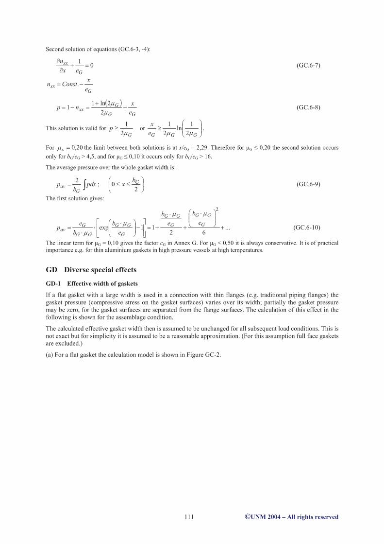
Second solution of equations (GC.6-3, -4):
01
G
xx
ex
n (GC.6-7)
Gxx
e
xConstn .
GG
Gxx
e
xnp
2
2ln11 (GC.6-8)
This solution is valid for G
p2
1or
GGGe
x
2
1ln
2
1.
For 20,0G
the limit between both solutions is at x/eG = 2,29. Therefore for µG 0,20 the second solution occurs
only for bG/eG > 4,5, and for µG 0,10 it occurs only for bG/eG > 16.
The average pressure over the whole gasket width is:
pdxb
pG
av2
; 2
0 Gbx (GC.6-9)
The first solution gives:
...62
11exp
2
G
GG
G
GG
G
GG
GG
Gav
e
b
e
b
e
b
b
ep (GC.6-10)
The linear term for µG = 0,10 gives the factor cG in Annex G. For µG < 0,50 it is always conservative. It is of practical
importance e.g. for thin aluminium gaskets in high pressure vessels at high temperatures.
GD Diverse special effects
GD-1 Effective width of gaskets
If a flat gasket with a large width is used in a connection with thin flanges (e.g. traditional piping flanges) the
gasket pressure (compressive stress on the gasket surfaces) varies over its width; partially the gasket pressure
may be zero, for the gasket surfaces are separated from the flange surfaces. The calculation of this effect in the
following is shown for the assemblage condition.
The calculated effective gasket width then is assumed to be unchanged for all subsequent load conditions. This is
not exact but for simplicity it is assumed to be a reasonable approximation. (For this assumption full face gaskets
are excluded.)
(a) For a flat gasket the calculation model is shown in Figure GC-2.
©UNM 2004 – All rights reserved 111

Figure GC-2 Effective width of a flat gasket between two flanges
Notation: bGa = contact width; bGi = interim (ideal, calculated) width;
bGe = effective width; bGt = theoretical width;
Q = gasket pressure = comprssive stress.
Elastic rotation of both flanges:
21
21F
GF
F
GFGFF
E
hZ
E
hZF (GD.1-1)
Elastic deformation of gasket (for ): Gabx0
xke
x
G
FF 21 (k = abbreviation) (GD.1-2)
QKEd
dQEG 10 (GD.1-3)
211exp 10
1
01 KE
K
EKQ (GD.1-4)
The resultant gasket force is
dxQdF xGeG (GD.1-5) Gabx0
acting at x = c, given by:
xdxQcdxQc xx (GD.1-6) Gabx0
From this follows step by step:
31
2
1 120
GaGeG
bkKbkEdF
Ga (GD.1-7)
Ga
Ga
Ga
bkK
bkK
bc
1
1
3
11
3
81
3
2 (GD.1-8)
©UNM 2004 – All rights reserved 112

31
2
1210
GaFFGe
GGGa
bkKEd
eFb (GD.1-9)
31
41
3
22
1
1
Ga
Ga
GaGaGi bkK
bkK
bcbb
210
9
8
FFGe
GG
GiEd
kFeF
b (GD.1-10a)
where 3
1
21
31
41
Ga
Ga
bkK
bkK
kF (GD.1-10b)
For «1 is GabkK1
21
1
1 GabkKkF (GD.1-11)
With , where Q is an average value, equation (GD.1-7) gives QbdFGeGeG
31
2
10
GaGa
GeGa
bkKb
bQbkE (GD.1-12)
This value is required only in F(k) and connected to the (not very essential factor) K1. Therefore the only rough
approximation QbkE Ga0 may be accepted. Further is simplified 19
8. Then:
elGe
FFGe
GGGi b
QKEd
eFb
21021
(GD.1-13)
This is the equation for the elastic behaviour of the gasket, where 21 FF
are to be substituted by equation
(GD.1-1). For the plastic behaviour is assumed:
maxQd
Fb
Ge
GplGe (GD.1-14)
True elasto-plastic deformation gives an effective width greater than for pure elastic and pure plastic
deformation; approximately:
GiplGeelGeGe bbbb 22 (GD.1-15)
The denomination bGi is used for the real effective width is limited as follows:
GtGiGe bbb ;min (GD.1-16)
Note that the elastic modulus EG = E0 + K1 Q it is defined and measured for unloading/reloading (see GB-6).
Here it is used for initial loading also, because validated data for loading are missed.
(b) For a gasket with curved surfaces (simple contact) the following was calculated:
For elastic deformation (Hertzian contact) the contact width and the maximum contact pressure are:
GeGGGa
dErFb
2
22 132
(GD.1-17)
©UNM 2004 – All rights reserved 113

GaGe
G
bd
FQ
4max (GD.1-18)
It is assumed this maximum contact pressure Qmax within the contact width bGa is equal the mean contact
pressure Q over the effective gasket widt bGe:
GaGe
G
bd
FQQmax (GD.1-19)
Therefore:
4GaGe bb (GD.1-20)
GeGGGe
dErFb
2
21
2 (GD.1-21)
Finally here is simplified 61 22 (similar to 8/9 1 for flat gaskets). The plastic effects are assumed equal
as for flat gaskets.
GD-2 Required internal forces
The required internal forces in flange connections are given by two general requirements:
(1) No loss of contact at all contact surfaces in all load conditions.
(2) Sufficient gasket pressure to prevent leakage in all load conditions.
In all subsequent conditions both requirements are represented by the following formula (G.6-9):
IRIQIGeIG FFQAF ;max minmin (GD.2-1)
In the assembly condition with I = 0 this formula also should be respected (although Q(0)min is under discussion),
however it is not sufficient:
Only by a sufficient large bolt load in assemblage the required gasket forces in the subsequent conditions can be
guaranteed. Therefore it must be {Formulae (GB.7-6) and (G.6-10), (G.6-11)}:
GG
IRRIRIRIQIQIGIGG F
Y
UYFYFYFYFF
0
00min0 (GD.2-2)
or
reqGGGG FFFF 0min00 ;max (GD.2-3)
GD-3 Scatter of bolt-load in assemblage
All bolt-tightening methods involve some degree of inaccuracy. The real bolt load in the assemblage load
condition (after bolt-tightening) therefore more or less deviates from the intended bolt load. The deviations have
a statistic character. The scatter-values are named by . They are assumed to decrease if the number of bolts
increases. Possibly the scatter values above the nominal load are different from the scatter values below
the nominal load.
For a connection with nB bolts the scatter depending relations are (see G.6.5.2):
max,0,0min,0 BnomBB FFF (GD.3-1)
nnomBB FF 1,0min,0 ; nnomBB FF 1,0max,0 (GD.3-2)
4
31
1B
n
n;
4
31
1B
n
n (GD.3-3)
To ensure that the flange connection is tight (also for the minimum forces) and not overloaded (also for the
maximum forces) the following relations should be met (compare (GA-1)):
allowableBBnomBBreqB FFFFF ,0max,0,0min,0,0 (GD.3-4)
Therefore the bolting up parameters are to be defined for FB0,nom with the following conditions:
©UNM 2004 – All rights reserved 114

nnomBreqB FF 1,0,0 (GD.3-5)
GD-4 Plastic deformation after assemblage, multiple assemblages
Due to the foregoing requirements {equations (GD.2-3) and (GD.3-5) } the real bolt load in assemblage always
is higher (may be considerably higher) than that required for the subsequent load conditions. Therefore a limited
lowering of the bolt load due to small plastic deformations may and shall be permitted. The design for
subsequent load conditions could be based on FG(0) = FG . However repeated plastic deformation due to repeated
dismounting and reassemblage must be avoided. To avoid progressive distortion the plastic deformation is to be
limited: The design for subsequent load conditions should be based on FG(0) = FG(0)d, where the design assembly
gasket load FG(0)d may be greater than FG .
The following considerations gives an estimation for FG(0)d :
Assemblage with a bolt load FB(0)max produces a maximal strain max. (Do not interchange max and the scatter
value ±). NR -times change of the bolt load from FB(0)max to a lower actual bolt load FB(0)act and back, in the worst
case is connected with a cumulative strain change:
max0
0max 1
B
actBRR
F
FN (GD.4-1)
It should be limited
maxCR (GD.4-2)
RBactB
N
CFF 1max00 (GD.4-3)
For usual materials the nominal design stresses are such that max 0,001 … 0,002, while the elongations
at rupture are rupt 0,1 … 0,2. Therefore the factor C could be assumed (conservative) as follows:
10C (GD.4-4) 20...5C
If for subsequent load conditions is used a design load FB(I)d, the usual safety factor 1,50 against yield stress
guarantees that plastic deformations will not occur for FB(I)act < 1,5 FB(I)d. Therefore the minimum design
assembly bolt load to define the calculation bolt load in subsequent load conditions is assumed:
RBactBdB
N
CFFF 1
3
2
3
2max00min,0 (GD.4-5)
This gives immediately:
0max00 13
2;max R
RBGdG F
N
CFFF (GD.4-6)
Based on the foregoing considerations an important hint to useful application of the method shall be given:
Normally for flange connections three or more load conditions are considered: Assemblage-, Test- and Operating
(one or more) conditions. The test pressure is higher than the operating pressures and therefore (by FG ) it
determines the required bolt load in assemblage. If one calculation is made for all three or more load conditions,
the test condition may be applied at any time, also after some operating cycles; the high bolt load required for
test is conserved over the operation cycles. This however in general is not necessary.
Normally the test pressure applies only once after assemblage, not after operating cycles. Therefore it may be
useful to make two calculations as follows: one for assemblage and all operating conditions, and a second for
assemblage and test condition. The second gives the more strong and therefore governing assemblage
requirements. During operating conditions possibly (not necessary) the bolt load lowers and the test pressure
then should not be allowed. However - if FB(0)d,min is met - this is no problem: After dismounting and
reassemblage all requirements are fulfilled!
GD-5 Load transfer diameter for loose flanges
The load transfer diameter d7 is the diameter of the circle where the resultant force (FB) between the loose flange
and the stub or collar acts. The value d7 is yet undetermined but limited: d7,min d7 d7,max. For large internal
fluid pressure P and/or positive additional force FR obviously d7 will be near d7,min. For assemblage without P
and FR may be expected d7 near d7,max. If there is a flat soft gasket over the whole width of the stub or collar, the
©UNM 2004 – All rights reserved 115

diameter d7 may be calculated for equal rotation of loose flange and stub or collar: FL . In assemblage
with FQ = FR = 0 it follows:
00
L
LLBL
E
ZhF ;
00
F
FGBF
E
ZhF (GD.5-1)
2
73 ddh e
L ; 2
7 GeG
ddh (GD.5-2)
073
71
ddd
d eGe ; 0
0
LF
FL
EZ
EZ (GD.5-3)
In equation (G.5-63) this equation is combined with the basic limits d7,min d7(0) d7,max.
GD-6 Conditions of applicability
The method Annex G gives many restrictions and validity limits. Some of them are short repeated and explained
in the following:
- The whole assembly is axisymmetric. Small deviations such as those due to a finite number of bolts are
permitted. There are four or more identical, uniformly distributed bolts.
Axisymmetric geometry and loading are basically for all included calculations.
Identical bolts are normally in use. The minimum number four is a compromise.
- The circular gasket is located entirely within the bolt circle on plane surfaces and compressed axially. Its
modulus of elasticity may increase with the compressive stress Q on the gasket.
Full face gaskets (bolt holes within the gasket width) for simplicity are not taken into account.
Otherwise it would be necessary the effective gasket width to determine different for each load condition.
Gaskets outside the bolt circle are omitted for their only exceptional use.
Gaskets on plane surfaces are mentioned for possible unexpected leakages at uneven surfaces.
Gaskets compressed axially are mentioned for e.g. radially tightening gaskets are not
respected.
The variable modulus EG = E0 + K1 Q is an approximation for a more general behaviour.
It is necessary to respect that in each case always must be EG > 0. (E0 < 0 is unacceptable!).
- The flange dimensions met the following conditions:
0,2 bF/eF 5,0; 0,2 bL/eL 5,0 and eF max {e2 ; dB0; pB· {(0,01 ... 0,10) ·pB/bF }1/3
The first limits are estimated for the acceptance of the ring with an undeformed cross section.
For bF/eF 0,1 commonly are assumed calculations for shells; for 10 bF/eF those for plates.
The reduced allowable load ratio max < 1,0 for d4/d0 > 2,0 equation (G.7-2) has a similar
reason.
It was introduced in TGL 32903/13 [8] for safety reasons; probably it can be waived.
The last limit (more precise in G.8.1) is intended to restrict the non-uniformity of the gasket
compressive stress. It is based on a conservative estimate for the non-axisymmetric
deformation of the flange ring. It was included after discussion in CEN; probably it can be
waived. An alternative could be a comparable estimate to include in the check for tightness.
- The shell met the condition cos S 1/{ 1+0,01 · } ss ed /
This limit is introduced for the analytic solution for the elastic shell is approximately only (see
Annex GB-1 here). A numerical verification with two different computer programs shows no
serious contradictions, but it gave no better or more general solution.
GD-7 Experimental verification
The CEN REPORT [9] to EN 1591-1 in its Annex B gives information about measurements for bolt load and/or
tightness of nearly 20 flange connections (diameter 50mm, 100mm, 400mm, up to 1200mm). All measurements
more or less precise verify the basic calculations for required and actual forces.
©UNM 2004 – All rights reserved 116

GE Future work
(1) The simplification of equal elastic moduli and equal temperatures for flange and shell shall be omitted.
Different materials and temperatures of flange and shell should be respected. This requires (instead of the
used equivalent cylindrical shells) more precisely to investigate conical hub and shell, both for elastic
deformation and for limit load.
(2) Possibly present washers shall be explicitly included in the calculation. This includes to define dimensions
and material properties of the washers, but it is no problem.
(3) Some corrections could be recommendable to be compatible with future "Heat exchanger tubesheet flange
connections" (see Annex J-5). This includes e.g. to calculate a circular plate with a thicker flange at the outer
diameter, where the midplane of the plate is not those of the flange.
Also flange connections with non axisymmetric loadings could be calculated (also Annex J-5).
Instead of the limitation G.8.1 this effect then could be included in the check for tightness.
(4) It will be necessary to update the method so that the results of new gasket investigations may be applied (e.g.
[11], probably a new edition of EN 1591-2 [10]). However surely then again new gasket parameters will be
required which are not available, e.g. data for irreversible deformation.
(5) Possibly the effective gasket width could be calculated variable with the loading and depending on the load
cases. Then the to day open questions for full-face flanges and for spacer-seated flanges may be solved.
GF Bibliography
[1] Wesstrom, D.B. and Bergh, W.D.: "Effect of Internal Pressure on Stresses and Strains in BoltedFlanged
Connections"; Transactions of the ASME, July, 1951.
[2] Materialy k edinym normam i metodam rasceta na procnost sosudov i apparatov.
(Basics to unifyed normes and methods for strength calculation of vessels and apparates.)
Sovjet Ekonomiceskoj Vsaimopomoshci, Postojannaja Komissija po Mashinostroeniju, Sekcija
No. l2 (COMECON, Permanent Commission for Engineering, Section No. 12), Moskva, 1963:
6: "Flancevije sojedinenija" (Clause 6: Flange connections): Authors: Karasev, L.P. i Perzev, L.P.
[3] DIN 2505 (Vornorm Okt.1964, Entwurf Nov.1972, Vornorm Jan. 1986, Entwurf April 1990)
"Berechnung von Flanschverbindungen". Teil 1: Berechnung; Teil 2: Dichtungskennwerte.
[4] RichtlinienKatalog Eestigkeitsberechnungen (RKF), Behälter und Apparate; Teil 1, BR-A13:
"Apparatebauelemente. Flanschverbindungen" (Flange connections); Dresden 1971. 1973;
VEB Komplette Chemieanlagen Dresden, 1979 (Author: J.Wölfel).
[5] Wölfel, J. und Räbisch, W.: "Berechnung und Standardisierung von Flanschverbindungen"
Chemische Technik, Leipzig, August 1975.
[6] TGL 20360 (1977) "Flanschverbindungen. Berechnung auf Festigkeit und Dichtigkeit"
[7] Wölfel, J.: "Berechnung der Festigkeit und Dichtigkeit von Flanschverbindungen"
Maschinenbautechnik, Berlin, Juni 1985.
[8] TGL 32903/13 (1983) "Behälter und Apparate. Festigkeitsberechnung. Flanschverbindungen"
[9] CR 13642 (1999): CEN REPORT: "Flanges and their joints - Design rules for gasketed circular
flange connections - Background information"
[10] EN 1591-1: 2001: "Flanges and their joints - Design rules for gasketed circular flange connections
Part 1: Calculation method" (EN 1591-2: Gasket parameters.)
[1l] PERL = Pressure Equipment, Reduction of Leak rate: Gasket parameters measurement.
Project funded by the European Community (1998-2002). Coordinator: ASE Ltd Cambridge UK.
©UNM 2004 – All rights reserved 117