backbar, keg & bottle coolers...operation, installation and instruction manual for backbar, keg...
TRANSCRIPT
Operation, Installation andInstruction Manual
for
Backbar, Keg & Bottle CoolersAnd
Backbar, Glass & Plate Chillers
A Division of National Refrigeration & Air Conditioning Products, Inc.539 Dunksferry Road • Bensalem, PA 19020-5908
215-244-1400 • 1-800-523-7138 • Fax: 215-244-9579www.continentalrefrigerator.com
REV:09/2004
Operators Manual
Table Of Contents Page
Receiving Your New Model ............................................................................................3General Information And Important Operating Facts ......................................................3Uncrating Your New Model ............................................................................................4Installation And Location ................................................................................................4Clearance........................................................................................................................4Ventilation........................................................................................................................4Floor Loads ....................................................................................................................5Mounting Equipment In Place ........................................................................................5Installing Legs And Leveling ..........................................................................................5Installing Casters And Leveling ......................................................................................7Installing Condensate Evaporator ..................................................................................7Initial Cleaning Procedure ..............................................................................................8Start-Up Procedure ........................................................................................................8Electrical Connections ....................................................................................................8115 Volt, 60 Hz, 1 Phase Connection ............................................................................9208-230 Volt, 60 Hz, 1 Phase Connection......................................................................9Special Voltage Connections ..........................................................................................9Start-Up Checklist ..........................................................................................................9Remote Applications ......................................................................................................10Operation ......................................................................................................................10Refrigerator System And Adjustment ............................................................................10Evaporator Assembly ....................................................................................................11Interior And Exterior Accessories ..................................................................................11Bottle Cap Catcher Installation ......................................................................................11Wire Storage Bin Divider Installation..............................................................................11Keg Cooler Set-Up & Installation Instructions................................................................12Installation Of Towers And Cold Air Tubes ....................................................................12Installation Of CO2 Cylinder And Regulator ..................................................................13
Keg Tapping Instructions................................................................................................13Safety Precautions ........................................................................................................15Maintenance ..................................................................................................................15Periodic Cleaning Procedure ........................................................................................15Precautions ....................................................................................................................16General Preventative Maintenance................................................................................16Parts And Service ..........................................................................................................16Troubleshooting And Servicing Guide............................................................................18Wiring Diagrams ............................................................................................................21Warranty ........................................................................................................................23

3
RECEIVING YOUR NEW MODELCongratulations on your recent purchase of continental refrigerator superior food
equipment products! When your shipment arrives, please thoroughly examine the
shipping crate for any punctures, dents, or signs of rough handling. It is in your
best interest to partially remove or open the shipping container in order to examine
the model for any concealed damages which may have occurred during shipment.
If the model is damaged, it must be noted on the delivering carrier's delivery slip or
bill of lading (see “filing a damage claim” under warranty section).
GENERAL INFORMATION AND IMPORTANT OPERATING FACTSThis manual has been compiled to aid in the installation, operation and maintenance
of your new equipment. Please take the time to read all of the material in order to
become more familiar with your equipment and its operation, and enjoy optimum
performance.
No floor drains or plumbing connections are required since all models are
completely self-defrosting and uses a non-electric, automatic defrost, condensate
water evaporating system (see “condensate evaporator installation” under installation
and location section). A clean out drainage hose has been provided behind the front
grill for cabinet clean out convenience.
All cabinets must be given sufficient time to reach normal operating temperature before
placing any product inside. Approximately 2 hours of operation are required to lower
the cabinet temperature to 38°F (see “operation” section for further information).
Freezers require approximately 3 hours of operation to lower the cabinet temperature
to 5°F.
Prior to factory shipping, all models are performance run tested for a minimum of 12
hours providing a highly sophisticated temperature analysis recording exclusive to
each individual cabinet. This recording is supplied within this manual packet. A final
leak check, vibration, noise level and visual examination is made by a qualified quality
control team to assure a quality product. The carrier signs to this effect when he
accepts the product for shipping. To insure the maximum in safety and sanitation, all
models are listed under the reexamination service of underwriter's laboratories and
with the national sanitation foundation.

4
UNCRATING YOUR NEW MODEL
The shipping container should remain on your model as protection against dents
or scratches while transporting it to the actual set-up location. Remove the shipping
container only at the last possible moment by following these simple steps:
1. Using a pry bar, pry off and remove crate end bottom staples.
2. Pry off and remove crate front and rear bottom staples.
3. Slide crate upward and remove it, being careful not to rub against cabinet.
There are up to four (4) bolts securing the cabinet to the wooden skid. The bolts are
located at each end on the underside of the skid. In order to remove these bolts it is
advisable to tilt the cabinet backwards and place wooden blocks at each end in order
to hold it in its tilted position. Using a 3/4" socket or open end wrench, remove the bolts
and carefully slide the model off of the skid. After skid removal, the cabinet should
never be moved without dollies or rollers to avoid damage to the cabinet bottom or
floor.
Important Note: Do not under any circumstances lay your new model on its front
or sides. Only for a brief period, may you lay the model on its back and only then,when
it's properly blocked so as not to crush the condensate drain tubing and also to allow
provision for your hands in order to set it in its upright position without inflicting
damage to the cabinet. Do not plug in and operate model for at least three (3)
hours after cabinet is set upright from being on its back as damage could result
to the compressor.
INSTALLATION AND LOCATION
CLEARANCESBefore moving the cabinet to its final point of installation, accurately measure all
doorways or passages to assure clearance. If additional clearance is needed,
cabinet bumpers can be easily removed.
VENTILATIONThe final location site of your air cooled, refrigerated bottle cooler must be able to
provide a large quantity of cool, clean air. The refrigeration system operates most
efficiently and trouble-free with cool, dry air circulation. Avoid locations near heat and
moisture generating equipment such as stoves, ovens, cooking ranges, fryers, dish
washers, steam kettles, etc., and also direct sunlight where temperatures can be in
excess of 100 degrees f. Also, do not select a location in an unheated room or area
where temperatures may drop below 55 degrees f. Air supply to the condensing unit
is equally important. Restricting the air supply will place an excessive heat load on
the condensing unit and adversely affect its operating efficiency.
5
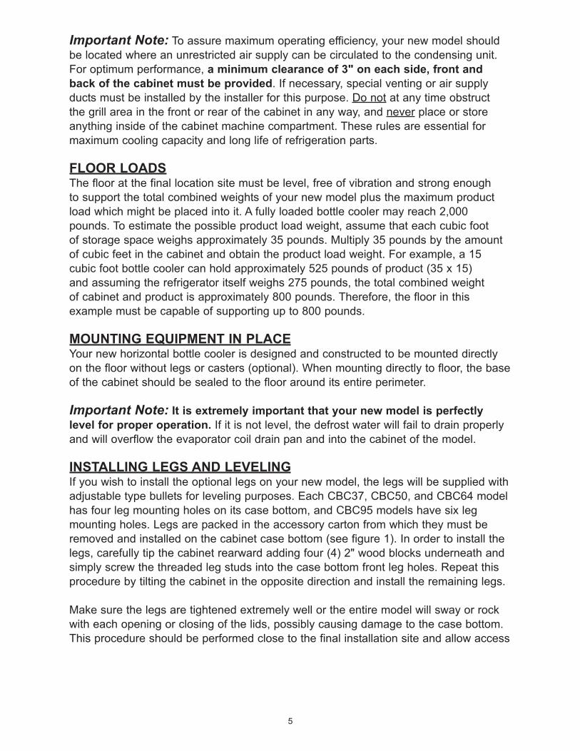
Important Note: To assure maximum operating efficiency, your new model should
be located where an unrestricted air supply can be circulated to the condensing unit.
For optimum performance, a minimum clearance of 3" on each side, front and
back of the cabinet must be provided. If necessary, special venting or air supply
ducts must be installed by the installer for this purpose. Do not at any time obstruct
the grill area in the front or rear of the cabinet in any way, and never place or store
anything inside of the cabinet machine compartment. These rules are essential for
maximum cooling capacity and long life of refrigeration parts.
FLOOR LOADSThe floor at the final location site must be level, free of vibration and strong enough
to support the total combined weights of your new model plus the maximum product
load which might be placed into it. A fully loaded bottle cooler may reach 2,000
pounds. To estimate the possible product load weight, assume that each cubic foot
of storage space weighs approximately 35 pounds. Multiply 35 pounds by the amount
of cubic feet in the cabinet and obtain the product load weight. For example, a 15
cubic foot bottle cooler can hold approximately 525 pounds of product (35 x 15)
and assuming the refrigerator itself weighs 275 pounds, the total combined weight
of cabinet and product is approximately 800 pounds. Therefore, the floor in this
example must be capable of supporting up to 800 pounds.
MOUNTING EQUIPMENT IN PLACEYour new horizontal bottle cooler is designed and constructed to be mounted directly
on the floor without legs or casters (optional). When mounting directly to floor, the base
of the cabinet should be sealed to the floor around its entire perimeter.
Important Note: It is extremely important that your new model is perfectly
level for proper operation. If it is not level, the defrost water will fail to drain properly
and will overflow the evaporator coil drain pan and into the cabinet of the model.
INSTALLING LEGS AND LEVELINGIf you wish to install the optional legs on your new model, the legs will be supplied with
adjustable type bullets for leveling purposes. Each CBC37, CBC50, and CBC64 model
has four leg mounting holes on its case bottom, and CBC95 models have six leg
mounting holes. Legs are packed in the accessory carton from which they must be
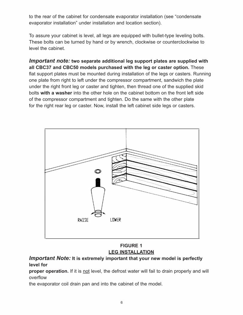
removed and installed on the cabinet case bottom (see figure 1). In order to install the
legs, carefully tip the cabinet rearward adding four (4) 2" wood blocks underneath and
simply screw the threaded leg studs into the case bottom front leg holes. Repeat this
procedure by tilting the cabinet in the opposite direction and install the remaining legs.
Make sure the legs are tightened extremely well or the entire model will sway or rock
with each opening or closing of the lids, possibly causing damage to the case bottom.
This procedure should be performed close to the final installation site and allow access
6
to the rear of the cabinet for condensate evaporator installation (see “condensate
evaporator installation” under installation and location section).
To assure your cabinet is level, all legs are equipped with bullet-type leveling bolts.
These bolts can be turned by hand or by wrench, clockwise or counterclockwise to
level the cabinet.
Important note: two separate additional leg support plates are supplied with
all CBC37 and CBC50 models purchased with the leg or caster option. These
flat support plates must be mounted during installation of the legs or casters. Running
one plate from right to left under the compressor compartment, sandwich the plate
under the right front leg or caster and tighten, then thread one of the supplied skid
bolts with a washer into the other hole on the cabinet bottom on the front left side
of the compressor compartment and tighten. Do the same with the other plate
for the right rear leg or caster. Now, install the left cabinet side legs or casters.
FIGURE 1
LEG INSTALLATION
Important Note: It is extremely important that your new model is perfectly
level for
proper operation. If it is not level, the defrost water will fail to drain properly and will
overflow
the evaporator coil drain pan and into the cabinet of the model.
7
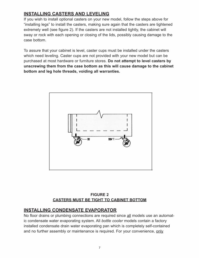
INSTALLING CASTERS AND LEVELINGIf you wish to install optional casters on your new model, follow the steps above for
“installing legs” to install the casters, making sure again that the casters are tightened
extremely well (see figure 2). If the casters are not installed tightly, the cabinet will
sway or rock with each opening or closing of the lids, possibly causing damage to the
case bottom.
To assure that your cabinet is level, caster cups must be installed under the casters
which need leveling. Caster cups are not provided with your new model but can be
purchased at most hardware or furniture stores. Do not attempt to level casters by
unscrewing them from the case bottom as this will cause damage to the cabinet
bottom and leg hole threads, voiding all warranties.
FIGURE 2
CASTERS MUST BE TIGHT TO CABINET BOTTOM
INSTALLING CONDENSATE EVAPORATORNo floor drains or plumbing connections are required since all models use an automat-
ic condensate water evaporating system. All bottle cooler models contain a factory
installed condensate drain water evaporating pan which is completely self-contained
and no further assembly or maintenance is required. For your convenience, only

8
evaporator condensate drains into this pan and cabinet washout drainage water has its
own hose located behind the front grill for easy disposal during cabinet cleaning.
Important Note: Cabinet washout drainage hose can be accessed behind the
front grill for easy disposal of water during cleaning.
INITIAL CLEANING PROCEDUREPrior to start-up and before placing any bottles inside of your new model, the interior
of the cabinet should be thoroughly cleaned. Washing with a mild soap and warm
water solution is recommended for cleaning the galvanized and stainless steel
surfaces of your cabinet. This should be followed by cleaning with a baking soda
solution (three (3) tablespoons of baking soda to each quart of warm water). Rinse
thoroughly with clear water and dry with a clean, soft cloth.
Important Note: Never use harsh detergents, cleaners, scouring powders or
chemicals when cleaning your model. Failure to dry the interior surfaces after
cleaning may result in a streaking or staining of the metal.
Complete cleaning procedures and precautions are listed in the “periodic cleaning
procedure” under the maintenance section.
START-UP PROCEDUREELECTRICAL CONNECTIONSTo insure proper operation, your new model must be connected to an individual
circuit that can supply the full voltage as stated on the cabinet serial data plate. For
correct voltage, power draw, and wire accommodations, check the data on the serial
data plate located on the inner right wall of your new model. Verify that this information
exactly matches the electrical characteristics at the installation location. An electrical
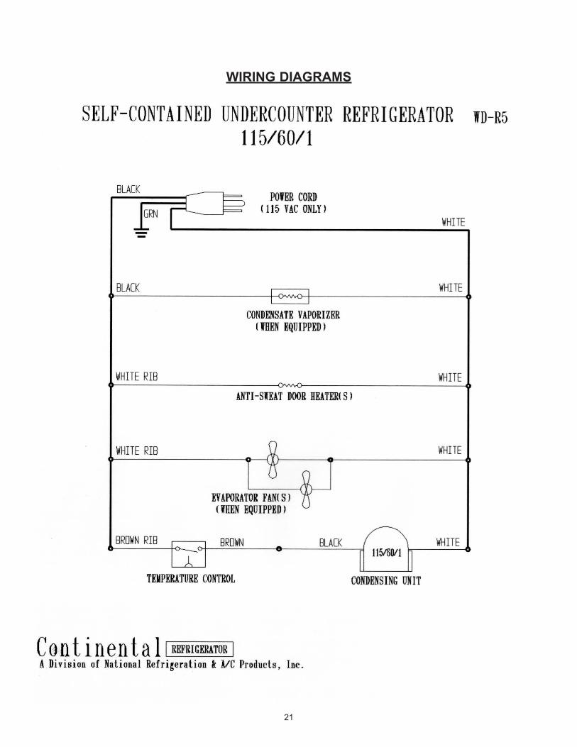
wiring diagram, located on the inside compressor compartment end panel next to the
electrical console box, should also be consulted during connection. For reference, a
copy of the electrical wiring diagram is located at the rear of this manual.
Important Note: The condensing unit supplied with all self-contained models is
designed to operate with a voltage fluctuation of + 10 % of the voltage indicated on
the cabinet serial data plate. Full voltage of the correct service, on an individual line
not affected by the operation of other electrical appliances, must be available to the
condensing unit at all times. Burnout of the compressor due to exceeding the
high or low voltage limits is easily detected and will automatically void the
factory warranty.

9
115 VOLT, 60 HZ, 1 PHASE CONNECTION
All 115 volt models are provided with a U.L. approved power cord and polarized plug
which is factory installed.
Warning: any alterations to this cord and plug could cause an electrical hazard
and will void the factory warranty.
To insure proper operation, this equipment must be plugged into a NEMA 5-15R
compatible, grounded receptacle that can supply the full voltage as stated on the
serial data plate.
208-230 VOLT, 60 HZ, 1 PHASE CONNECTION
All 208-230 volt models are to be permanently connected and are provided with
four (4) field wiring leads which exit the electrical console box located in the
machine compartment behind the rear grill. The cabinet circuitry is 115 volts and
the condensing unit is 208-230 volts in which the wiring includes a neutral and a
mechanical ground. This wiring should be connected to the appropriate power
source by a qualified electrician and must conform to all local electrical codes.
SPECIAL VOLTAGE CONNECTIONS
When models are ordered from the factory with special, optional voltages, connections
should be made as required on the electrical wiring diagram provided on the inside
compressor compartment end panel next to the electrical console box.
START-UP CHECKLIST
After your model has been installed, leveled, cleaned, and electrically connected
in accordance with this manual, please take the time before start-up to observe the
following precautions to assure trouble-free operation:
1. Check that all exposed refrigeration lines are free of severe dents or kinks.
2. Check the condenser fan and evaporator fans for freedom to rotate without
any obstructions
3. Make sure that the cabinet is properly leveled (see “leveling” under
installation and location section).
The system should run smoothly and quietly in accordance with generally accepted
commercial standards. If any unusual noises are heard, turn the unit off immediately
and check for any obstructions of the condenser or evaporator fans. Fan motors, fan
blades, or fan housings can be jarred out of position through rough handling in transit
or during installation.
10
Caution: if unit is unplugged or disconnected for any reason, allow several minutes
(5-6 minutes) before turning the unit back on to allow the system pressures to equal-
ize. Disregarding this procedure could cause an overload and prevent the unit from
operating.
REMOTE APPLICATIONSAll models are available for purchase as remote models in which case the condensing
unit is purchased separately and installed at the time of installation. All remote models
are equipped with an expansion valve located within the evaporator coil housing, and
both liquid and suction lines stubbed and extending out from the cabinet condensing
unit compartment behind the front and rear grill. Installation of the refrigeration
accessories, condensing unit, and electrical hook-up should be performed by
qualified refrigeration personnel of a competent refrigeration company only.
OPERATIONAll cabinets must be given sufficient time to reach normal operating temperature
before placing any product inside. Refrigerated bottle coolers are designed to
maintain an ideal cabinet temperature of 34°F to 38°F (1.1°C to 3.3°C) and
approximately 3 hours of operation are required to reach this temperature.
REFRIGERATOR SYSTEM AND ADJUSTMENTAll self-contained bottle cooler refrigerators are designed and factory set to maintain
an average cabinet temperature of 36°F. The temperature control is accessible inside
of the cabinet product compartment, on the right back wall next to the evaporator coil.
See figure 3 for thermostat location. If an adjustment is necessary to maintain the
above temperature range only, place a screwdriver into the thermostat slot and turn
clockwise for a colder cabinet temperature or counterclockwise for a warmer cabinet
temperature. Further adjustments out of the factory design temperature range must
be made by a qualified refrigeration mechanic only.
Important Note: All refrigerators are designed with an automatic; “off-cycle” defrost
system which means that defrosting occurs automatically when the compressor is not
operating during an off-cycle. Do not set the thermostat too cold where the cabinet
temperature will fall below 33°F because the evaporator will become blocked by ice
since the compressor off-cycle will be considerably shortened. This will result in loss
of food stored within the cabinet and require service to defrost the evaporator and
re-adjust the thermostat.

11
EVAPORATOR ASSEMBLYAll continental bottle cooler refrigerators have an easily accessible, easily serviceable,
performance rated, forced-air evaporator assembly which utilizes a plasticized fin coil
for extended life. All models utilize a full length, extra large evaporator coil which pro-
vides uniform air flow distribution for quick top row product chilling. The evaporator
assembly system is shown in figure 3.
Warning: Do not place hands up and under fan motor housing during operation
since fan blade is located here.
INTERIOR AND EXTERIOR ACCESSORIESThe standard accessory package that is supplied from the factory with your new
continental bottle cooler consists of one (1) small wire storage bin divider for all
models, one (1) large wire storage bin divider for CBC37 models, two (2) large wire
storage bin dividers for CBC50 models, three (3) large wire storage bin dividers for
CBC64 models, and seven (7) large wire storage bin dividers for CBC95 models.
All wire bin dividers come with mounting springs (one per bin divider). Also enclosed
is a bottle cap opener and bottle cap catcher assembly (CBC95 models contain two
assemblies).
BOTTLE CAP CATCHER INSTALLATIONTo attach the bottle cap catcher assembly to the front of the cabinet, loosen the two
exposed mounting screws above the grill assembly and simply hang the bottle cap
catcher on the screws using the provided key-slot holes. To remove the bottle cap
catcher for emptying or cleaning, just lift up and pull the catcher towards you.
WIRE STORAGE BIN DIVIDER INSTALLATIONInstall the small wire bin divider first by inserting mounting spring over the long
extension as shown in figure 3, and then pushing the long extension into any one
of the six fan cover bushing holes. Be sure to disconnect power when installing
or removing the small wire bin divider only - fan may interfere with long
extension causing damage to your model.
Now, push the bin divider towards the rear of the cabinet compressing the mounting
spring almost all of the way and insert the front of the bin divider into its respective
hole location in the interior cabinet front. The mounting spring will keep the wire bin
divider in place and power can now be restored to your model. The large wire bin
dividers can now be installed in the same manner as the small bin dividers but, in
their respective holes as shown in figure 3.
Important Warning: Always disconnect the power to your bottle cooler when
installing or removing the small wire bin divider since the long extension on the
bin divider may interfere with the fan and damage could result to your bottle
cooler causing your warranty to become null and void.

12
KEG COOLER SET-UP & INSTALLATION INSTRUCTIONS(Refer to drawing on next page)
INSTALLATION OF TOWERS AND COLD AIR TUBESTo install cooling tower(s), place rubber washer over tower mounting holes in cabinet
top and secure tower(s) onto top using fine thread machine screws supplied on cabinet
FIGURE 3
EVAPORATOR ASSEMBLY AND STORAGE BIN DIVIDER INSTALLATION

13
top (do not use wood screws supplied with tower). Beer line from tower must go
through hole in top and attaches to keg tap (not supplied).
The cold air tubes coming from the grill inside of the cabinet can be installed by simply
pushing each tube as far as it will go into its closest tower hole. About eight inches of
tube will feed into the tower.
INSTALLATION OF CO2 CYLINDER AND REGULATORA CO2 tank up to five pounds in size (not supplied) may be placed inside the
cabinet on the step or remoted outside of the cabinet. If remoted outside of cabinet,
a knock-out plug on the step floor is provided for convenience for the CO2 hose.
The CO2 dispensing gas must be reduced to an 8-10 PSI by a regulator (not supplied).
The regulated gas must be delivered to the manifold splitter (located on the left upper
wall of cabinet) using the supplied hose and clamps. Size and cut hose as necessary.
The manifold splitter will separate the gas into two or more lines to supply gas to each
keg tap. A check valve is installed on the manifold splitter to prevent beer from backing
up into the supply hose and regulator.
KEG TAPPING INSTRUCTIONSBecause keg and tap types vary from brand to brand, contact your beer distributor for
specific keg tapping instructions.
Important Notes: For you convenience, a beer spillage and clean out drain hose
has been provided and is located behind the front grill. Approximately 3 ft of hose is
supplied for an external drainage connection to be made by installer. The drain line
(located on the left front interior floor) can be cut if a beer waste jar is desired for
interior installation.
Defrosting is automatic but because door openings for loading can vary in time it is
recommended that the unit be unplugged with the doors left open for at least fifteen
minutes during the keg changing.
The thermostat control (located on the left rear interior of cabinet) is factory set to
maintain your beer keg temperatures within the most desirable range of 35° F to
40° F under normal conditions. It may take several hours to cool a warm keg so it
is important to install cold purchased kegs inside the cooler immediately to avoid
warm-up of beer.Before a new barrel is tapped, the CO2 lines should be purged by
quickly opening and closing the regulator outlet valve, allowing a surge of gas to
travel through the line and tap.
Proper cleaning is extremely important for the beer faucet, drain pan or any item
coming in contact with food or beverages to prevent odors and tastes from bacteria.
It is normal for some sweating to occur on or around each draft tower, and around
door openings under conditions of high humidity

1414
15
SAFETY PRECAUTIONSThe following safety precautions should be followed when operating any appliances:
� Always disconnect the power cord before attempting to work on or clean
any equipment.
� Disconnect the power cord when the appliance will be idled for a long
period of time.
� Do not attempt to service this unit yourself as removing any covers may
cause exposure to dangerous voltage.
� Always route the power cord so that it is not likely to be walked on or
pinched by other appliances. Never use extension cords.
� Do not overload outlets with more than one appliance. This can result in
fire or electrical-shock
� Your model is equipped with a grounded and polarized plug. Do not defeat
the purpose of this plug by removing the ground post or using a non-
polarized adapter without properly grounding the outlet.
Never connect any appliance to a power source while standing in water or with wet
hands.
When a replacement part is required, always insist on factory authorized parts only.
MAINTENANCE
PERIODIC CLEANING PROCEDUREIt is best to clean your continental bottle cooler when the product load is at its lowest
level inside your cabinet. To clean the interior or exterior cabinet surfaces, the following
procedure should be
followed:
1. Disconnect your model from its power supply and remove all product from
inside.
2. Open all doors and allow the cabinet to reach room temperature. Remove
all accessories (shelves, racks, pilasters, clips, etc.) from within the model,
wash with a baking soda and warm water solution, and rinse thoroughly with
clear water. Dry all of the accessories completely with a soft clean cloth.
3. Once the cabinet has reached room temperature, wash the entire cabinet
inside and out with a baking soda and warm water solution. For slightly
more difficult cleanups, ammonia or vinegar in warm water can be used.
Rinse thoroughly with clear water and dry with a soft clean cloth.
Failure to dry all surfaces completely may cause water stains or streaking
on the aluminum or stainless steel finish.
4. Return all accessories to their respective positions and return electric supply
power to the model.
16
PRECAUTIONS1. Never use harsh detergents, cleaners, scouring powders, or chemicals when
cleaning your model.
2. Strong bleaches tend to corrode many materials and should never come in
contact with stainless steel.
3. Tincture of iodine, or iron should not come in contact with stainless steel.
These solutions, which cause stainless steel to discolor, should be rinsed off
immediately if contact occurs.
4. Gritty, hard abrasives will mar the finish of stainless steel and aluminum and
are not recommended.
GENERAL PREVENTATIVE MAINTENANCEPerformance of the air cooled condensing unit located on the bottom of your new
model, depends exclusively upon the amount of air passing through the condenser
fins. Your refrigerator will run more efficiently, consume less current, and provide a
maximum of trouble-free service throughout its lifetime if the condenser is kept clean
and an adequate supply of clean, cool air is provided at all times. Periodically (at least
once a month) inspect the condenser coil, which is located directly behind the front
grill, to check for debris or blockage.
If the condenser coil is dirty or blocked, disconnect the power supply to your model
and using a stiff brush, brush the dirt from the condenser fins until the condenser is
clear from any debris. Using a vacuum cleaner with a brush attachment may aid in
this cleaning process. After cleaning, restore electrical service to your model.
PARTS AND SERVICEAlways provide the cabinet model and serial number (located on the data plate
on the inside right wall of the cabinet) whenever contacting the factory or your
dealer regarding questions or when ordering parts.
17
MODEL # _____________ SERAL#_______________
Notes:
____________________________________________________________________________________________________________________________________________________________________________________________________________________________________________________________________________________________________________________________________________________________________________________________________________________________________________________________________________________________________________________________________________________________________________________________________________________________________________________________________________________________________________________________________________________________________________________________________________________________________________________________________________________________________________________________________________________________________________________________________________________________________________________________________________________________________________________________________________________________________________________________________________________________________________________________________________________________________________________________________________________________________________________________________________________________________________________________________________________________________________________________________________________________________________________________________________________________________________________________________________________________________________________________________________________________________________________________________________________________________________________________________________________________________________________________________________________________________________________________________________________________________________________________________________________________________________________________________________________________________________________________________________________________________________________________________________________________________________________________________________________________________________________________________________________________________________________________________________________________________________________________________________________________________________________________________________________

18
TROUBLESHOOTING AND SERVICING GUIDE
PROBLEM PROBABLE CAUSE CORRECTION
Condensing unit will 1.Line Disconnected, Switch Open. 1.Close Start Or Disconnect
not start - no hum. Switch.
2.Fuse Removed Or Blown. 2.Replace Fuse.
3.Overload Protector Blown. 3.Determine Reason And
Correct/Replace.
4.Control “Off” Due To Cold Location. 4.Relocate Control.
5.Control Stuck In Open Position. 5.Repair Or Replace Control.
6.Wiring Improper Or Loose 6.Check Wiring Against Diagram.
Condensing unit will 1.Improperly Wired. 1.Check Wiring Against Diagram.
not start - hums but 2.Low Voltage To Unit. 2.Determine Reason And Correct.
trips on overload 3.Starting Capacitor Defective. 3.Determine Reason And Replace.
protector. 4.Relay Failing To Close. 4.Determine Reason And Replace.
5.Compressor Motor Has A Shorted Or 5.Replace Compressor.
Open Winding.
6.Internal Mechanical Trouble In 6.Replace Compressor.
Compressor.
7.Insufficient Air Supply. 7.Clean Condenser & Allow
Compressor To Cool Down.
Condensing unit 1.Additional Current Passing Through 1.Check Wire Diagram Check For
starts and runs, but Overload Protector. Added Components Connected
short cycles on over- To Wrong Side Of Overload
load protector. Protector.
2.Low Voltage To Unit 2.Determine Reason And Correct.
3.Overload Protector Decfective. 3.Check Current, Replace Protector.
4.Run Capacitor Defective. 4.Determine Reason And Replace.
5.Excessive Discharge Pressure. 5.Check Ventilation, Restrictions In
Cooling Medium Or Refrig. System.
6.Excessive Suction Pressure. 6.Check For Misapplication.
7.Insufficient Air Supply 7.Clear Condenser & Allow
Compressor To Cool Down.
Condensing unit 1.Improperly Wired. 1.Check Wiring Against Diagram.
starts, but fails to 2.Low Voltage To Unit. 2.Determine Reason And Correct.
switch off of “start” 3.Relay Failing To Open. 3.Determine Reason And Replace.
winding. 4.Run Capacitor Defective. 4.Determine Reason And Replace.
5.Excessively High Discharge Pressure. 5.Check Discharge Shut-Off Valve,
Possible Overcharge.
6.Compressor Motor Has A Shorted Or 6.Replace Compressor.
Open Winding.
7.Internal Mechanical Trouble In Compressor. 7.Replace Compressor.

19
PROBLEM PROBABLE CAUSE CORRECTION
Condensing units runs 1.Overload Protector. 1.See Problem # 3.
but short cycles on: 2.Thermostat. 2.Differential Must Be Widened.
3.High Pressure Cut-Off Due To: 3.
(a) Insufficient Air Supply. (a) Check Air Supply To Condenser.
(b) Overcharge. (b) Evacuate And Re-Charge.
(c) Air In System. (c) Evacuate And Re-Charge.
4.Low Pressure Cut-Off Due To: 4.
(a) Valve Leak. (a) Replace, Evacuate, And Re-
Charge.
(b) Undercharge (b) Evacuate And Recharge
(c) Restriction In Expansion Device. (c) Replace Expansion Device.
Condensing unit runs 1.Shortage Of Refrigerant. 1.Fix Leak, Evacuate And Recharge.
but for prolonged 2.Control Contacts Stuck Closed. 2.Clean Contacts Or Replace
periods or continuous. Control.
3.Excessive Heat Load Placed Into 3.Allow Unit Sufficient Time For
Cabinet. Removal Of Latent Heat.
4.Prolonged Or Too Frequent Door 4.Plan Or Organize Schedule To
Opens. Correct Condition.
5.Evaporator Coil Iced. 5.Defrost Evaporator Coil.
6.Restriction In Refrigeration System. 6.Determine Location And Remove
7.Dirty Condenser. 7.Clean Condenser Coil.
8.Filter Drier Clogged. 8.Replace, Evacuate And Re-charge.
Start capacitor open, 1.Relay Contact Not Opened Properly 1.Clean Contacts Or Replace Relay.
shorted or blown. 2.Prolonged Operation On Start Cycle: 2.
(a) Low Voltage To Unit. (a) Determine Reason And Correct.
(b) Improper Relay. (b) Replace With Correct Relay.
(c) Starting Load Too High. (c) Correct By Using Pump Down.
3.Excessive Short Cycling. 3.Determine Reason For Short Cycle
(See Problem #5) And Correct.
4.Improper Capacitor. 4.Determine Correct Size And
Replace.
Run capacitor open, 1.Improper Relay 1.Check Size And Replace.
shorted or blown. 2.Excessively High Line Voltage, Over 2.Determine Reason And Correct.
110% Of Rated Maximum.
Relay defective or 1.Incorrect Relay 1.Check Relay And Replace.
blown out. 2.Incorrect Mounting Angle. 2.Remount Relay In Correct Position
3.Voltage Too Low Or Too High. 3.Determine Reason And Correct.
4.Excessive Short Cycle. 4.Determine Reason And Correct
(See Problem # 5)
5.Loose Or Vibrating Mounting Position. 5.Remount Rigidly.
6.Incorrect Run Capacitor. 6.Replace With Proper Capacitor.
7.Loose Wiring On Relay Or Overload 7.Tighten All Wiring Screws.
20
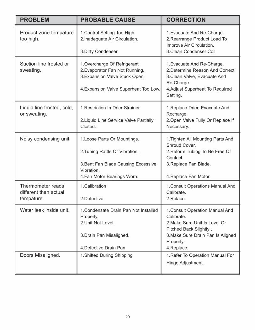
PROBLEM PROBABLE CAUSE CORRECTION
Product zone tempature 1.Control Setting Too High. 1.Evacuate And Re-Charge.
too high. 2.Inadequate Air Circulation. 2.Rearrange Product Load To
Improve Air Circulation.
3.Dirty Condenser 3.Clean Condenser Coil
Suction line frosted or 1.Overcharge Of Refrigerant 1.Evacuate And Re-Charge.
sweating. 2.Evaporator Fan Not Running. 2.Determine Reason And Correct.
3.Expansion Valve Stuck Open. 3.Clean Valve, Evacuate And
Re-Charge.
4.Expansion Valve Superheat Too Low. 4.Adjust Superheat To Required
Setting.
Liquid line frosted, cold, 1.Restriction In Drier Strainer. 1.Replace Drier, Evacuate And
or sweating. Recharge.
2.Liquid Line Service Valve Partially 2.Open Valve Fully Or Replace If
Closed. Necessary.
Noisy condensing unit. 1.Loose Parts Or Mountings. 1.Tighten All Mounting Parts And
Shroud Cover.
2.Tubing Rattle Or Vibration. 2.Reform Tubing To Be Free Of
Contact.
3.Bent Fan Blade Causing Excessive 3.Replace Fan Blade.
Vibration.
4.Fan Motor Bearings Worn. 4.Replace Fan Motor.
Thermometer reads 1.Calibration 1.Consult Operations Manual And
different than actual Calibrate.
tempature. 2.Defective 2.Relace.
Water leak inside unit. 1.Condensate Drain Pan Not Installed 1.Consult Operation Manual And
Properly. Calibrate.
2.Unit Not Level. 2.Make Sure Unit Is Level Or
Pitched Back Slightly .
3.Drain Pan Misaligned. 3.Make Sure Drain Pan Is Aligned
Properly.
4.Defective Drain Pan 4.Replace.
Doors Misaligned. 1.Shifted During Shipping 1.Refer To Operation Manual For
Hinge Adjustment.
21
WIRING DIAGRAMS

22
23
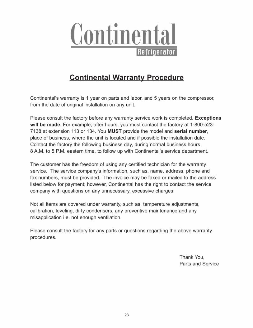
Continental Warranty Procedure
Continental's warranty is 1 year on parts and labor, and 5 years on the compressor,
from the date of original installation on any unit.
Please consult the factory before any warranty service work is completed. Exceptions
will be made. For example; after hours, you must contact the factory at 1-800-523-
7138 at extension 113 or 134. You MUST provide the model and serial number,
place of business, where the unit is located and if possible the installation date.
Contact the factory the following business day, during normal business hours
8 A.M. to 5 P.M. eastern time, to follow up with Continental's service department.
The customer has the freedom of using any certified technician for the warranty
service. The service company's information, such as, name, address, phone and
fax numbers, must be provided. The invoice may be faxed or mailed to the address
listed below for payment; however, Continental has the right to contact the service
company with questions on any unnecessary, excessive charges.
Not all items are covered under warranty, such as, temperature adjustments,
calibration, leveling, dirty condensers, any preventive maintenance and any
misapplication i.e. not enough ventilation.
Please consult the factory for any parts or questions regarding the above warranty
procedures.
Thank You,
Parts and Service
24
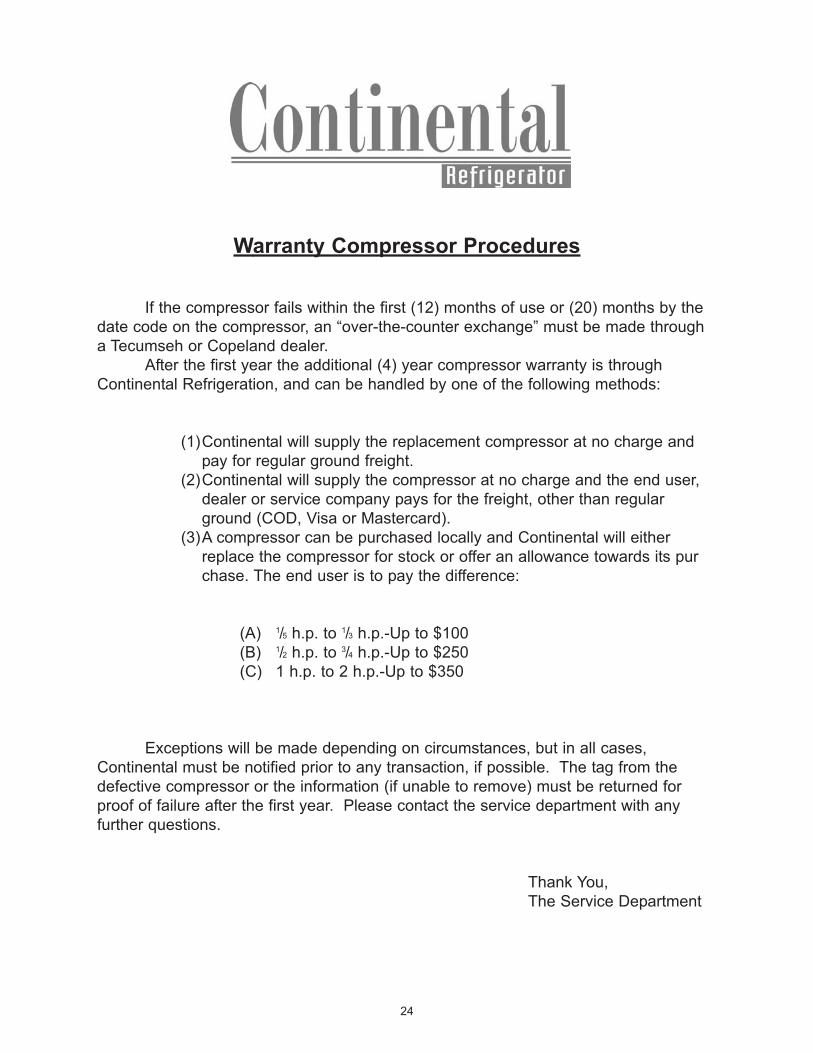
Warranty Compressor Procedures
If the compressor fails within the first (12) months of use or (20) months by thedate code on the compressor, an “over-the-counter exchange” must be made througha Tecumseh or Copeland dealer.
After the first year the additional (4) year compressor warranty is throughContinental Refrigeration, and can be handled by one of the following methods:
(1)Continental will supply the replacement compressor at no charge and pay for regular ground freight.
(2)Continental will supply the compressor at no charge and the end user, dealer or service company pays for the freight, other than regular ground (COD, Visa or Mastercard).
(3)A compressor can be purchased locally and Continental will either replace the compressor for stock or offer an allowance towards its purchase. The end user is to pay the difference:
(A) 1/5 h.p. to 1/3 h.p.-Up to $100(B) 1/2 h.p. to 3/4 h.p.-Up to $250(C) 1 h.p. to 2 h.p.-Up to $350
Exceptions will be made depending on circumstances, but in all cases,Continental must be notified prior to any transaction, if possible. The tag from thedefective compressor or the information (if unable to remove) must be returned forproof of failure after the first year. Please contact the service department with any further questions.
Thank You,The Service Department
25
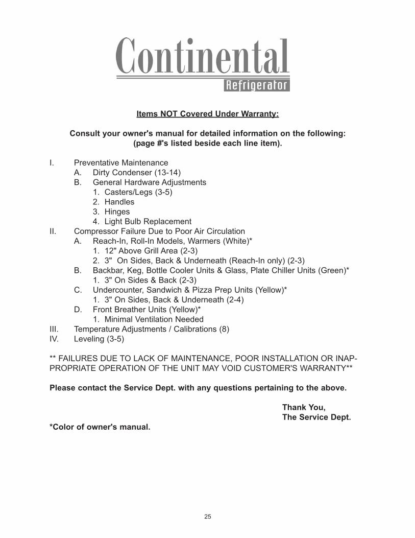
Items NOT Covered Under Warranty:
Consult your owner's manual for detailed information on the following:
(page #'s listed beside each line item).
I. Preventative MaintenanceA. Dirty Condenser (13-14)B. General Hardware Adjustments
1. Casters/Legs (3-5) 2. Handles 3. Hinges 4. Light Bulb Replacement
II. Compressor Failure Due to Poor Air Circulation A. Reach-In, Roll-In Models, Warmers (White)*
1. 12" Above Grill Area (2-3)2. 3" On Sides, Back & Underneath (Reach-In only) (2-3)
B. Backbar, Keg, Bottle Cooler Units & Glass, Plate Chiller Units (Green)*1. 3" On Sides & Back (2-3)
C. Undercounter, Sandwich & Pizza Prep Units (Yellow)*1. 3" On Sides, Back & Underneath (2-4)
D. Front Breather Units (Yellow)*1. Minimal Ventilation Needed
III. Temperature Adjustments / Calibrations (8)IV. Leveling (3-5)
** FAILURES DUE TO LACK OF MAINTENANCE, POOR INSTALLATION OR INAP-PROPRIATE OPERATION OF THE UNIT MAY VOID CUSTOMER'S WARRANTY**
Please contact the Service Dept. with any questions pertaining to the above.
Thank You,
The Service Dept.
*Color of owner's manual.