> - oilweb standard_old/std-187.pdf · drilling / work-over rig ,crane and other associated...
TRANSCRIPT
<< Back Home Next >>

2
FOREWORD The Oil Industry in India is more than 100 years old. Because of various collaboration agreements, a variety of international codes, standards and practices have been in vogue. Standardisation in design philosophies and operating and maintenance practices at a national level was hardly in existence. This coupled with feed back from some serious accidents that occurred in the recent past in India and abroad, emphasised the need for the industry to review the existing state of art in designing, operating and maintaining oil and gas installations. With this in view, the Ministry of Petroleum and Natural Gas in 1986 constituted a Safety Council assisted by the Oil Industry Safety Directorate(OISD) staffed from within the industry in formulating and implementing a series of self regulatory measures aimed at removing obsolescence, standardising and upgrading the existing standards to ensure safe operations. Accordingly, OISD constituted a number of functional committees of experts nominated from the industry to draw up standards and guidelines on various subjects. The present standard on " Care and Use of Wire Rope " was prepared by the Functional Committee on " Care and Use of Wire Rope” This document is based on the accumulated knowledge and experience of industry members and the various national and international codes and practices. This standard is meant to be used as supplement and not as a replacement for existing codes and practices. It is hoped that provisions of this standard if implemented objectively, may go a long way to improve the safety and reduce accidents in Oil and Gas Industry. Users are cautioned that no standard can be a substitute for the judgement of responsible and experienced Drilling Engineers.
Suggestions are invited from the users after it is put into practice to improve the document further. Suggestions for amendments to this document should be addressed to the Coordinator,
Committee on "Care and Use of Wire Rope”
OIL INDUSTRY SAFETY DIRECTORATE 7TH FLOOR, NEW DELHI HOUSE
27, BARAKHAMBA ROAD NEW DELHI - 110 001.
This standard in no way supercedes the statutory requirements of bodies like DGMS, CCE or any other Government Body which must be followed as applicable.
3
COMMITTEE FOR STANDARD ON
"CARE AND USE OF WIRE ROPE" ----------------------------------------------------------------------------------------------------------------------------- NAME DESIGNATION & POSITION IN ORGANISATION COMMITTEE ---------------------------------------------------------------------------------------------------------------------------- S/SHRI 1. RAM SHANKER ONGC LEADER 2. G.C. SAIKIA OIL MEMBER 3. P.K. JAIN ONGC MEMBER 4. N.M. RAI ONGC MEMBER 5. P.K. GARG OISD CO-ORDINATOR JAYANT AHUJA OISD CO-ORDINATOR ----------------------------------------------------------------------------------------------------------------------------

4
CONTENTS SECTION DESCRIPTION PAGE NO.
1. INTRODUCTION 5
2. SCOPE 5 3. DESCRIPTION 5 4. STORAGE OF WIRE ROPE 7 5. HANDLING OF WIRE ROPES & REELS 7 6. CARE DURING OPERATIONAL USE OF WIRE
ROPE 8
7. SLINGS 9 8. INSPECTION OF WIRE ROPE 13 9. WIRE ROPE REPLACEMENT 16
10. LUBRICATION OF WIRE ROPES OF CRANE AND OTHER ROPES
18
11. LUBRICATION SYSTEM 18 12. CLAMPING OF WIRE ROPES AND TESTING 19 13. CASING LINE AND REEVING PRACTICE 21 14. EVALUATION OF ROTARY DRILLING LINE 21 15. SLIPPING & CUT OFF PRACTICE FOR ROTARY
DRILLING LINES 24
16. FIELD TROUBLES , CAUSES AND REMIDIAL MEASURES
26
17. DO’S AND DON’TS 30 18. GLOSSARY 31 15. REFERENCES 31
19. ANNEXURES 32

5
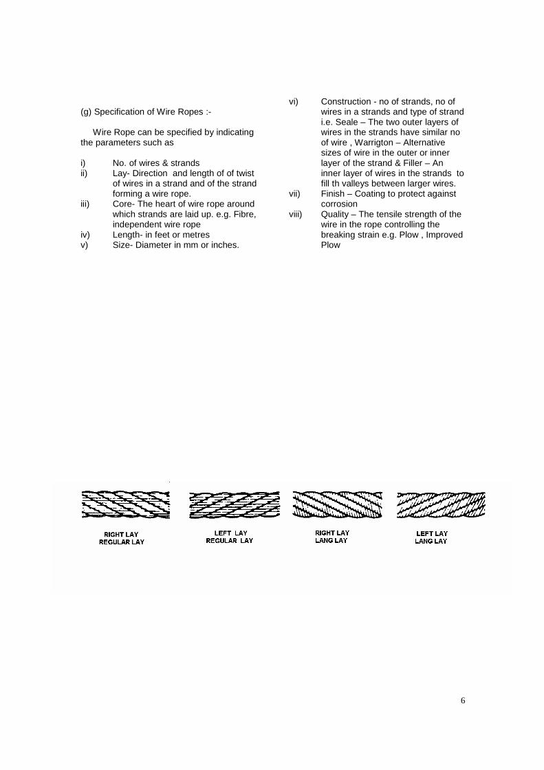
1.0 INTRODUCTION Wire rope is an important component of the Drilling / Work-over rig ,crane and other associated equipment jobs related to oil industry. Wire rope requires periodic checkup and replacement, in order to compensate the possible loss of strength resulting from wear, abuse, and other forms of deterioration. The wire rope must be carefully selected, maintained, inspected and replaced to prevent any accident that may cause loss of life injury to people, loss of property, process and damage to the environment. This standard has been prepared keeping in view the salient aspects of wire rope inspection, maintenance and replacement. 2.0 SCOPE This standard covers various aspects related to Storage of wire ropes, handling of wire ropes & reels, Care & handling of slings, Lubrication of Wire rope, slings & other ropes, various lubrication system and clamping of ropes and its testing. This standard also covers Evaluation of Rotary drilling line, its slipping & Cut off practice and the various Field troubles, causes and its remedial measures. 3.0 DESCRIPTION 3.1 Wire Rope: i) Wire rope is made of number of strands laid helically around a core. It consists of three basic components:- a) The Core : Core is in the centre of wire rope. It may consists of fibre – natural or synthetic, stranded wire or a complete “ Independent Wire Rope Core”. b) The multi -wire strands that are helically laid around the core. c) The individual wires that formed the strands ii) Wire ropes are classified into various types based on type of construction viz.type of strands construction, no. of strands / wires etc. as stated below: a) Regular Lay
The wires are laid in one direction and the strands in other , so that the visible wires appear running parallel to the rope axis. In this construction a rope under tension may rotate as the strands unwind . but at the same time the wires in the strands are being twisted more tightly and a balance is thus reached between the two opposing rotational forces. On relaxation of the tension on the rope it will return to its normal state. This construction has a greater resistance than Lang’s Lay to drum crushing when multi-layered. b) Lang’s lay In Lang’s lay the wires and strands are laid in the same direction so that the visible wires run at an angle of about 300 to the rope axis. Thus longer lengths of each wire are presented as a wearing surface to spread abrasion. c) Direction of Lay The direction of lay or rotation of the strands is normally right hand , but some machinery needs left hand lay ropes. d) Lay Length It is the length of rope in which one strand makes one helical revolution round the core. This may be expressed as X mm or as X x rope diameter. A short lay rope has more elasticity than a long lay rope and the lay length is dictated by the application for which the rope is intended. e) Type of Wire Rope Details of Typical sizes and construction of wire rope for Oil Field services are placed in Annexure I f) Selection Of Wire Rope The selection of Wire Rope is based on the following points / parameters :- Required strength - Tensile strength of
Wire Rope Fatigue factor - Construction & Tensile
strength of Rope Shock Resistance- Construction and lay
length Abrasion effect - Construction , Tensile
strength and lay length Crushing - Type of Core
6
(g) Specification of Wire Ropes :- Wire Rope can be specified by indicating the parameters such as i) No. of wires & strands ii) Lay- Direction and length of of twist
of wires in a strand and of the strand forming a wire rope.
iii) Core- The heart of wire rope around which strands are laid up. e.g. Fibre, independent wire rope
iv) Length- in feet or metres v) Size- Diameter in mm or inches.
vi) Construction - no of strands, no of wires in a strands and type of strand i.e. Seale – The two outer layers of wires in the strands have similar no of wire , Warrigton – Alternative sizes of wire in the outer or inner layer of the strand & Filler – An inner layer of wires in the strands to fill th valleys between larger wires.
vii) Finish – Coating to protect against corrosion
viii) Quality – The tensile strength of the wire in the rope controlling the breaking strain e.g. Plow , Improved Plow
7
4.0 STORAGE OF WIRE ROPES
i. Wire ropes should be stored in a well cleaned, ventilated dry shed, free as far as possible, from dust and fumes. The wire ropes should not be stored unless it has been cleaned thoroughly, greased and covered. These should be inspected for corrosion at regular intervals and recorded. These may need attention, as corrosion once started may develop rapidly.
ii. Wire ropes normally are supplied in
coils or reels. When in coil, they should be stored on wooden planks to keep them clear of the floor. Before uncoiling, wire ropes should be put on a turntable to prevent kinking.
iii. Wire ropes when supplied on reels,
before using, a spindle should be put through the reel and the ends are to be jacked up to allow the reel to rotate as the rope is pulled off.
iv. Special ground protected from rain and
dust should be prepared for storage. A useful rack to hold the reels may be constructed for use. This stand can be made portable if accommodation is limited.
v. Light duty slings are better to be stored
when hung so that they do not twist, while heavy slings are to be stored on wooden supports separately one from other and from other tool and equipment. In mobile crane operation, where slings need to be carried in the crane itself, necessary suitable boxes with lids to protect slings from dust and rain are provided at convenient place on the crane. After use each slings must be wiped dry, cleaned and lubricated periodically with first quality acid free lubricant.
5.0 HANDLING OF WIRE ROPES &
REELS Wire rope / Reels require careful handling so that maximum life can be achieved. The various points to be kept in view for proper handling are listed below.
5.1 HANDLING OF REEL / COIL DURING TRANSPORTATION
i. The reel / coil should not be dropped
from a hook or platform. This may cause damage to the rope and break the reel as well.
ii. The reel / coil should not be rolled or dropped over a hard/sharp object in such a manner that the rope will be bruised or nicked.
iii. Bars should be used against the reel flange and not against the rope.
iv. Use protective boards with slings to prevent crushing the line during handling / transportation of reel.
v. Do not put Heavy or sharp edge load on the coil during transportation.
5.2 HANDLING DURING INSTALLATION
i. Excess or Dead Wraps :- After properly securing the wire rope in the drum socket, the number of excess or dead wraps or turns specified by the equipment manufacturer should be maintained.
ii. New wire Rope :- On installation of new wire rope , It should be run under controlled load and speed for a short period after it has been installed. This will help to adjust the rope to working conditions.
iii. The reel should be set up on a substantial horizontal axis preferably on a stand so that it is free to rotate as the rope is pulled off.
iv. During rolling of reel/coil precautions should be taken to prevent picking of dirt/sand by wire rope.
v. Wire ropes should not be struck by any object such as a steel hammer, derrick hatchet or crow bar which may cause unnecessary nicks or bruises. In case it is necessary to ground rope together, any such operation should be performed with the great care. If a wire is covered with dirt or grit, it should be cleaned with a brush.
vi. Care should be taken to avoid kinking of wire rope. In case of a kink, the wires and strands are permanently misplaced and the relative balance between individual wires and strands has been disturbed. No matter how slight the damage may appear from a
8
superficial examination, the rope has been distorted and can never give the maximum life.
6.0 CARE DURING OPERATIONAL USE
OF WIRE ROPE 6.1 Tension on Rope. Tension should be maintained on the wire rope as it leaves the reel by restricting the reel movement. A timber or plank provides satisfactory brake action. When winding the wire rope on the drum, sufficient tension should, be kept on the rope to assure tight winding. 6.2 Kinking. Care should be taken to avoid kinking a wire rope since a kink can be a cause for removal of the wire rope of full length or damaged section, if it is at the ends. 6.3 Lubrication The service life of wire rope is directly proportional to the effectiveness of the lubrication of Rope , as it also protects the wire rope from abrasion , wear & corrosion.
6.4 New Wire Rope. Whenever possible, a new wire rope should be run under controlled loads and speeds for a short period after it has been installed. This will help to adjust the rope to working conditions. 6.5 Design Factor The design factor should be determined by the following formula: Design Factor = B / W Wherein: B= Nominal strength of the wire rope, lbs. W= fast line tension When a wire rope is operated close to the minimum design factor , care should be taken that the rope and related equipment are in good operating condition. At the times, the operating personnel should use diligent care to minimise shock, impact, and acceleration or deceleration of loads. Successful field operations indicate that the following design factors should be regarded as minimum.
Type of Line Minimum design Factor
Cable-tool l ine 3 Sand l ine 3 Rotary dr i l l ing l ine 3
Hoist ing serv ice other than rotary dr i l l ing 3 Mast ra is ing and lower ing l ine 2.5 Rotary dr i l l ing l ine when set t ing cas ing 2 Pul l ing on stuck pipe and simi lar inf requent operat ions
2

9
Wire rope life varies with the design factor, therefore longer rope life can generally be expected when relatively high design factors are maintained. 7.0 SLINGS 7.1 Care And Handling Of Slings The short wire rope lengths used to attach a load to the crane hoist line hooks are known as slings. It is essential to ensure that all operators, responsible for the use of slings should know, how to select the right sling to do the best and safest job possible. Examination of the load to be lifted must include an accurate determination of its weight. Selection of sling should always be of greater capacity than the actually needed to transport / lift the load. In case field made slings are to be used then it should be made by using proper size and number of wire rope clamps. Slings are very much prone to wear and tear during use and storage and as such, care should be taken while handling
these slings. These should be periodically examined for defects and deterioration. 7.2 Material Handling With The Slings It is recommended that the angle of spread between the legs of a sling should not exceed 90 degrees and this requirement can be met by increasing the length of the legs of the sling or by using a crossbar and attaching the sling legs to each end. In multi leg sling operation, the most favourable angle between the sling legs is within the range of 60 and 90 degrees. If this angle is more than 120 degrees , the effective load on each sling becomes even more than the load of the object being lifted and as such , the main purpose of using multi leg sling would be defeated. The Table 1a shows the reduction in lifting capacity of a two legged sling with respect of increase in the angle of spread (based on a 6 to 1 safety factor ) or in other terms as the angle of spread increases, tension on the slings increases.
Fig 1

10
Table 1 a Two Legged Slings Angle of spread 0 deg 30deg 60 deg 90 deg 120
deg Approx. Percentage reduction in lifting capacity
0% 3 ½% 13 ½% 29 ½% 50%
Table 1 b CHART SHOWING LOAD FIGURES. SlingAngle(From vertical) Load AngleFactor 0 1.000 50 1.004 100 1.015 150 1.035 200 1.064 250 1.104 300 1.155 350 1.221 400 1.305 450 1.414 500 1.555 550 1.742 600 2.000 650 2.364 700 2.924 750 3.861 800 5.747 850 11.49
Table 2 Eye Size (In.)
Rated Capacity (Tons)
Basket Hitch
Rope Size (In.)
W L
Recommended Minimum Length Straight
Pull Choker Hitch Vertical 300 450 600
¼ 3 6 1’ 6” 0.56 0.42 1.1 0.97 0.79 0.56 3/16 3 6 1’10” 0.87 0.65 1.7 1.5 1.2 0.87 3/8 3 6 1’ 10” 1.2 0.93 2.5 2.2 1.8 1.2 7/16 4 8 2’ 4” 1.7 1.3 3.4 2.9 2.4 1.7 ½ 4 8 2’ 6” 2.2 1.6 4.4 3.8 3.1 2.2 9/16 4 8 2’ 8” 2.8 2.1 5.5 4.8 3.9 2.8 5/8 5 10 3’ 2” 3.4 2.6 6.8 5.9 4.8 3.4 ¾ 6 12 3’ 8” 4.9 3.6 9.7 8.4 6.9 4.9 7/8 7 14 4’ 4” 6.6 4.9 13.0 11.0 9.3 6.6 1 8 16 4’ 10” 8.5 6.4 17.0 15.0 12.0 8.5 1 1/8 9 18 5’ 6” 10.0 7.8 21.0 18.0 15.0 10.0 [ Rope size – Diameter of wire rope,W & L of eye size and other terms are explained in fig of subsequent pages]
2
Basket Hitch:- A basket hitch is made by passing slings under the load with the weight of the load evenly distributed on two or more legs . Choker Hitch:- A choker hitch is made by passing the sling entirely under the load . One loop of sling is hooked through the sliding hook forming a slip noose. The other loop of the sling is placed on the hoist hook of the crane. Straight Pull :- It is made by attaching one end of the single sling directly to the load with a hook or shackle. The loop on the other end is placed over the crane hoist hook. When more than one sling is used , the rigging is called bridle sling, most bridle slings have two to four legs.
2
3
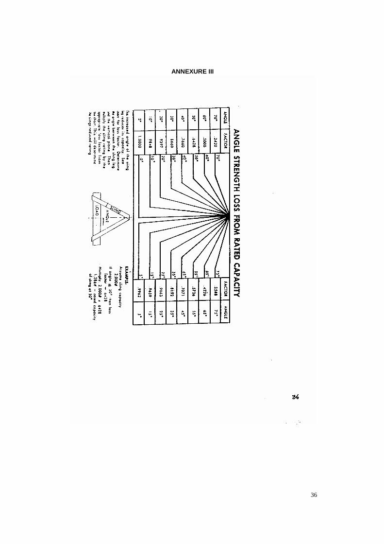
7.3 SLING RATINGS: The chart in Table 2 shows the load ratings of slings made of 6 x 19 IWRC (IPS) cable with mechanically spliced loops. The Table 2 gives ratings for slings used in a straight pull, a choker hitch, and in a basket hitch with the ratings given in tons for the various rope sizes listed in the first column. The load ratings for ¾” rope in a straight pull is 4.9 tons. When the same sling is used in a choker hitch the load rating drops to 3.6 tons because of the added strain on the rope at the point of the slip nose. When the sling is rigged vertically in a basket hitch it reaches its highest rating possible. As the chart shows, the ¾” sling used in a vertical basket hitch is rated for a load of 9.7 tons -the maximum weight this size sling can handle under any circumstances. The Fig 1 , Table 1b and Annexure provide a different way of looking at angular stress, and gives load angle factors that can be multiplied by the load weight to correct the tension factor for the given angle. The smaller the angle, the higher the load rating. For example, a 1000 Kg. load picked up with a 2 legged bridle sling places 500 Kg. of tension on each of the sling lines. If the angle of the sling is changed to 30 o from vertical, the load angle factor changes to 1.155 and the resulting tension increases to 577 Kg. per line (500 x 1.155). This increases to 707 Kg. per line with a 45o angle, and to 1000 Kg. with a 60o angle sling. In terms of rating, when rigged at a 30o angle from vertical, the ¾” sling rating would drop from 9.7 tons to 8.4 tons ( Refer Table 2). When an angle of a 45o is used, the rating drops again to 6.9 tons. When the angle further increase to 60o, the load rating drops to 4.9 tons which is equal to the rating of the sling used in a straight pull, in other words, the advantage of basket hitch (which shares the load weight on 2 legs) is lost when the sling is rigged at greater than 60o angle.
There is no change in the strength of the sling with the change in the sling angles; however, when the crane operator hoists a load, a sling rigged at an angle away from the vertical not only carries the vertical weight of the load, but also takes extra stress from the side. When rigging a load, a sling of sufficient length must be used whenever possible, to avoid a severe angle build up to 60o (300+300) or greater. However, due to the size or shape of the load and the slings available, some jobs may require the load be rigged with the legs of the sling at an undesirable angle. In this case spreader bars of proper design can be used to reduce sling angle on long loads. 8.0 INSPECTION OF WIRE ROPES 8.1 Frequent Inspection Of Wire Rope Eventually, all wire ropes will deteriorate to a point when these are no longer serviceable. There are four basic causes for rope deterioration. These are:
i. Abrasion or wear. ii. Corrosion iii. Fatigue caused by the pulling, bending,
crushing or kinking forces applied to the rope during normal service.
iv. Environmental conditions like temperature, continuous excessive moisture level, vapours, etc.
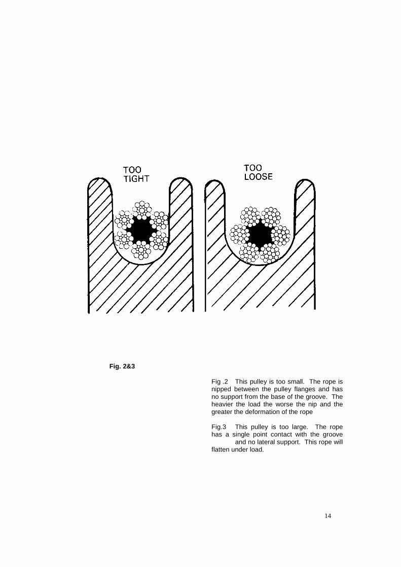
None of the above causes of deterioration can be eliminated entirely. However, all four can be minimised, thus ensuring the longest possible safe service life of the rope. v. It is essential to use right size of rope to the right size of sheaves, which will ensure safety to the rope. The following figures show the effect on ropes fitted to wrong size of sheaves:
However, being the mechanically spliced flemish eye with thimble ( the first method )is the the best and safest system for clamping wire ropes the three method discussed above on he other hand , Clamping of wire rope with ‘thimble and clips’ be avoided as far as possible in cranes in long run cases.
14
Fig. 2&3
Fig .2 This pulley is too small. The rope is nipped between the pulley flanges and has no support from the base of the groove. The heavier the load the worse the nip and the greater the deformation of the rope Fig.3 This pulley is too large. The rope has a single point contact with the groove and no lateral support. This rope will flatten under load.
15
vi. Dynamic Shock Loads: Subjecting wire rope to abnormal loads beyond the endurance limit will shorten the wire rope’s life expectancy. Examples of this type of loading are listed below: a) High velocity movement e.g., hoisting or
swinging of a load followed by abrupt stops.
b) Suspending loads while travelling over irregular surfaces such as railroad tracks, potholes and rough terrain.
c) Moving a load that is beyond the rated capacity of the lifting mechanism, i.e., overloading.
8.2 Inspection Procedure And Decision Making The first step toward proper care of wire rope is an inspection schedule. All wire ropes used in critical services (lifting of loads, etc.) should be inspected on a regular periodic basis, preferably at-least weekly. This inspection should be aimed at determining the degree of deterioration at the worst rope lay, since this will determine the suitability for continued service. By definition, a rope lay is the axial distance along the rope in which one strand makes one complete turn around the rope. The inspection should pay particular attention to the following:
i. Internal wear caused by grit penetrating between strands and wires.
ii. Kinks iii. Lubrication iv. Corrosion v. Number of broken strands per lay vi. The manner in which fittings are
attached vii. Condition of sheaves over which the
rope must pass, including sheave’s alignment.
viii. The amount of wear on outer wires. ix. Any evidence of serious rope
deterioration from corrosion should cause consideration to be given to replacing the rope.
x. Any of the following conditions should cause the inspector to question the remaining strength of a rope, and to give consideration to the possibility of discarding the rope.
a) If the core is seen through more than one pair of strands.
b) Kinking damage is severe. c) Evidence of improper lubrication,
combined with other defects. d) Wire that has come in contact with a
electrical circuit or that has been subject to overheating.
e) Serious reduction in rope diameter.
8.3 Frequent Inspection A frequent daily visual inspection is recommended for all running ropes in service. This inspection should be made on all wire ropes which can be expected to be in use during the day’s operation. This inspection should be used to monitor progressive degradation and to discover severe damages (necessitating wire rope replacement) such as:
i. Distortion, Kinking, Crushing, Un-stranding, Bird caging, Reduction of diameter, etc.
ii. General corrosion iii. Broken or cut strands iv. Number, distribution and type of
broken wires v. Evidence of core failure vi. End fitting wear / abrasion vii. Wire rope clips and nuts shall be
checked for tightness 8.4 Periodic Inspection Wire rope should be inspected periodically i.e. monthly or at a shorter time interval, if necessitated by environmental or other adverse conditions, and shall cover the entire length of the wire rope. Only the outer surface of the wire rope need be inspected, and no attempt should be made to open the rope. Inspection record should be maintained to determine the time interval for replacement of the rope. Periodic inspection should include all items listed under frequent inspection plus the following:
i. Inspect for reduction of rope diameter below nominal diameter.
ii. Inspect for severely corroded or broken wires at end connection.
iii. Inspect for severely corroded, cracked, bent worn, or improperly applied end connections.
iv. Inspect wire rope in areas subjected to rapid deterioration such as: Sections in

16
contact with saddles, equaliser sheaves, or other sheaves where wire rope travel is limited. Sections of wire rope at or near terminal ends where corroded or broken wires may protrude.
v. Inspect boom nose sheaves, hook block sheaves, boom extension / jib sheaves, auxiliary boom nose sheaves, and hoist drums for wear. Damaged sheaves or hoist drums can accelerate wear and cause rapid deterioration of the wire rope.
8.5 Statutory Inspection The lifting tackles, wire ropes, slings etc. to be thoroughly examined by a competent person at least once in every period of 12 months or at such intervals as the chief inspector may specify in writing and a register should be kept containing the details as per the Indian Factories Act 1948 –Section 29. Sub Rules 1.a(iii) and 2.
9.0 WIRE ROPE REPLACEMENT No precise rules can be framed for determination of the exact period of use & replacement of wire rope, as many variable factors of load /working conditions / environment. Its replacement is based
largely on remaining strength of wire rope in use after proper inspection and evaluation. All wire rope will eventually deteriorate to a point where it is no longer usable. Wire rope shall be taken out of service when any of the following conditions exist. a. In running ropes, six randomly
distributed broken wires in one lay or three broken wires in one strand in one lay.
b. Wear of 1/3rd of the original diameter of outside individual wires. Kinking, crushing, bird-caging, or any other damage resulting in distortion of the rope structure.
c. Evidence of any heat damage from any cause.
d. Reduction from nominal diameter for more than :
1/64 inch for diameters up to and including 5/16 inch. 1/32 inch for diameters 3/8 to 1/2 inch inclusive 3/64 inch for diameters 9/16 to 3/4 inch inclusive 1/16 inch for diameters 7/8 to 1 1/8 inches inclusive 3/32 inch for diameters 1 1/4 to 1 1/2 inches inclusive.

17
Fig. 4 a Fig 4 b [The diameter of a wire rope is identical to that of a true circle which would enclose the rope. To gauge a rope be sure that the faces of the calipers are in contact with the crowns of two opposite strands as in Fig.4a and not as in Fig.4 b in contact with four strands. To be certain that the calipers are in the contact position rotate them round the ropes the greatest measurement is correct. Failure to take this precaution may mean that the size noted is considerably less than the actual. NB After a rope has been in use it is sometimes possible to get two correct readings of its size varying considerably. This occurs when the rope has lost its shape due to crushing, but may occur at intermittent points throughout its length, should there be internal corrosion or should the core be damaged.] Wire rope removed from service , due to any of the above mentioned reasons, shall be identified and marked as unfit for use on crane or other load carrying devices.

18
10.0 CORROSION IN WIRE ROPES 10.1 Corrosion And Its Cause A very large number of ropes fail due to corrosion either external, internal, or both. This corrosion may be caused by a variety of reasons - the most common being acid or alkaline water, sea environment, fumes, due to industrial conditions etc. When any one or combination of these conditions is present, corrosion may attack the whole rope from end to end, but quite frequently the effects are intermittent throughout the length of the rope. These points are usually situated where the rope is in contact with the pulleys when no longer in use . Fumes , moisture etc. can accumulate between the rope and the pulley and may also penetrate the rope on the outside of the bend and rapidly set up corrosion. Corrosion in most cases cannot be completely prevented, but it can be resisted by cleaning and lubricating the ropes regularly, or by using galvanised ropes. 10.2 Resistance To Corrosion Wire ropes supplied are greased but this initial greasing is not sufficient to last the life-time of the rope. The rope must be kept clean. The deposit that forms on top of the grease coating holds moisture and gradually works into the strands until the grease becomes emulsified and if the deposit has an acid contact, the grease finally becomes corrosive - not only Externally but also Internally. After cleaning the rope with waste or hessian cloth , (do not use kerosene or gasoline as it may penetrate into the core and do away with the internal lubrication) - the rope must be re-greased with a first quality lubricant free from acid - such as petroleum jelly or special grease produced by the leading oil companies for this purpose. This should be applied either by hand or waste, and worked into the interstices between the strands. When corrosion is a serious obstacle to rope life it is usually better to use a galvanised rope. The galvanising will eventually wear off the outer wires where they come in
contact with pulleys, drums, etc. but will remain on inside the rope and give very good protection against internal corrosion. Ropes need periodical lubrication to resist corrosion . Lubrication keeps the ropes flexible and enables the wires to move in relation to each other. Periodic operation of rope is obligatory to prevent localized corrosion. 10.3 Methods Of Recognition of
Corrosion External corrosion most frequently occurs and fortunately can be easily recognised. The danger , however of internal corrosion is always present particularly when corrosion is already visible on the outside of the ropes . un-fortunately internal corrosion is much difficult to recognise in the early stages. 10.4 External Corrosion Clean the rope thoroughly at various points throughout its length, particularly at those points where it normally is in contact with sheaves, rollers, pulleys, etc., then examine the rope for encrusted rust and pitting. 10.5 Internal Corrosion
i. Under wet conditions, usually causes a
rusty emulsified oily liquid to exude between the strands under load.
ii. In an advance stage it can be recognised by slackness in the wires in each strand due to the internal wires corroding away.
iii. In a rope with an independent wire rope core or wire main core , the main core may corrode away and allow the outer strands to collapse and so reduce the overall dia. Of the rope at that point.
11.0 LUBRICATION SYSTEM Before applying lubrication, accumulations of dirt or other abrasive material should be removed from the rope. Cleaning can be accomplished by using a stiff wire brush and solvent, compressed air, or live steam. Immediately after the wire rope is cleaned, it should be lubricated.

19
The following are important characteristics of a good wire rope lubricant:
i. It should be free from acids and alkalis. ii. It should have sufficient adhesive
strength to remain on the ropes. iii. It should be of a viscosity capable of
penetrating the interstices between wires and strands.
iv. It should not be soluble in the medium surrounding it under the actual operating conditions (i.e. water).
v. It should have a high film strength. vi. It should resist oxidation. vii. It should be chemically stable. While doing lubricating the slings/wire ropes, people should wear hand gloves. Many techniques may be used for lubrication, these include bath, dripping, pouring, swabbing, painting or pressure spray methods. Whenever possible, the lubricant should be applied at the top of a bend in the rope, because at that point the strands are spread by bending and are more easily penetrated. There should be no load on the rope while it is being lubricated. It should be noted, the service life of wire rope will be directly proportional to the effectiveness of the method used and amount of lubricant reaching the working parts of the rope. Type of lubricant servo coat 110/120 or its equivalent can be used for lubrication or as recommended by the manufacturer of wire rope.
12.0 CLAMPING OF WIRE ROPES AND TESTING There are various methods of clamping the open end of a crane wire rope. The most commonly used and safe method is to have a mechanically spliced flemish eye (Loop) with thimble at the end The system provides a splice in which the ferrule and the wire rope , clamped under controlled pressure in an ISMAL press , becomes homogeneous. This type of splice has merits over the hand splice systems with saving in time for making splice, saving in material, no risk of injuries, increase in rope life. Another method of clamping is to use wedge and socket. In this system, it is essential to use only a wedge socket of the correct size for the rope fitted. Failure to do so may result in the rope pulling through the fitting as soon as the load is applied. The third method of clamping is to use thimble and drop forged wire rope clips. While fixing the clips, it is to be made sure that the ‘U’-bolt is around the dead-end (the short end) and the base is against the live part of the Rope. The following Table shows minimum number of drop-forged clips required to make a fastening having approximately 80 per cent of the strength of the wire rope.

20
Table 3 Dia of Rope No. of Clips Space between clips Length of Rope turned
back exclusive of eye Inches. mm. Inches. Mm. Inches. mm. 3/8 9 2 2 ¼ 57 5 127 1/22 13 3 3 76 9 229 5/8 16 3 3 ¾ 95 11 179 ¾ 19 4 4 ½ 114 18 457 7/8 22 4 5 ¼ 135 21 533 1 25 4 6 152 24 609 1 1/8 29 5 7 173 35 889 1 ¼ 32 5 8 203 40 1016 1 3/8 35 6 9 229 54 1372 1 1/2 38 6 10 254 60 1524

21
13.0 CASING -LINE AND DRILLING-LINE REEVING PRACTICE 13.1 Precautions To Avoid Casing Line Damage
i. For proper reeving of casing line during hoisting/lowering of travelling block, turn back rollers on both sides of draw-works should be fitted and maintained to prevent damage of casing line.
ii. Roller guide should be installed for better spooling of casing line.
iii. During drilling, dead line stabiliser should be installed wherever provision in the monkey board exists.
iv. Fast end should be clamped in the draw work properly and should be visually inspected daily and thoroughly in each round trip or even after every fishing/ complication etc.
v) Align the reel with the dead line anchor to avoid scrubbing against steel members.
vi. Line should be spooled from the bottom of a reel to the deadline anchor.
vii. Check all sheaves of crown block and travelling blocks for wear and tear condition. Worn sheaves can damage drilling line.
viii. When stringing up a line, use a wire line grip (snake) with swivel to prevent transferring twist to the drilling line.
ix. Check the clamp on the deadline anchor. The line must be firmly gripped to prevent slippage. If the clamp is too tight, the line will be crushed.
x. Provide a protective covering for the drilling line reel to protect against mud, corrosive fluids, water and wind-borne abrasives.
xi. Check the fleet angle to assure that the center of the drum is in line with the crown block fast sheave. This will help even spooling and reduces wear on the fast sheave.
xii. Periodically, a visual inspection should be made of drilling line as it is spooled on or off the drum. Weak places indicated by broken or worn wires or distortion of the line may be removed from the system by slipping and cutting the drilling line. Working stuck pipe or fishing operations can overload or
shock load to an extent that makes inspection advisable.
xiii. Drilling line should be slipped three to
five times between cut-offs to move stressed parts of the line.
xiv. Field lubrication may become necessary if the line looks dry. Use a lubricant recommended for wire rope.
xv. Cross bolts of dead end anchor should be in place and tightened to avoid jumping of casing line out of dead end spool.
14.0 EVALUATION OF ROTARY DRILLING LINE
The total service performed by a rotary drilling line can be evaluated by taking into account the amount of work done by the line in the various drilling operations (drilling, coring, fishing, setting casing, etc.).and by evaluating such factors as the stresses imposed by friction forces of the line in contact with drum and sheave surfaces, and other even more indeterminate loads. Drilling Rig should be equipped with ton mile (ton km) indicator and work done by rotary drilling line should be recorded daily in the register. Drilling line should be slipped and cut to avoid any accident as per the schedule. However, for comparative purposes, an approximate evaluation can be obtained by computing only the work done by the line in raising and lowering the applied loads in making round trips, and in the operations of drilling, coring, setting casing, and short trips. 14.1 Round-Trip Operations. Most of the work done by a drilling line is that performed in making round trips (or short trips) involving running the string of drill pipe into the hole and pulling the string out of the hole. The amount of work performed per round trip should be determined by use of the following formula : Tr =D( Ls+D )Wm + D( M+½C )-------------(a)
10,560,000 2,640,000
Tr =ton-miles (weight in tons times distance moved in miles). D = depth of hole ft. Ls = length of drill-pipe stand ft. N = number of stands of drill-pipe.

22
Wm= buoyed weight per foot of drill-pipe, lb., from M = total weight of travelling block-hook ,links etc. elevator lb. C = buoyed weight of drill-collar assembly from minus the buoyed weight of the same length of drill-pipe, lb., from In making a round trip, work is done in raising and lowering the travelling block assembly, and in running and pulling the drill stem, including the drill collar assembly and bit. The calculations are simplified by considering the drill pipe as extending the bottom of the hole and making separate calculations for the excess weight of drill collar bit assembly over that of the same length of drill pipe. In running the string, the travelling block assembly, which includes the travelling block, hook links, and elevator (weight M) moves a distance equal (approximately) to the twice the length of the stand (2 Ls), for each stand. The amount of work done is equal to 2MLsN. In pulling the string a similar amount of work is done, therefore, the total amount of work done in moving the travelling block assembly, during one complete round is equal to 4MLsN. Since the drill pipe is assumed to extend to the bottom of the hole, making LsN equal to D, the total work done can be expressed as 4DM in pound feet or 4DM -------------------- , in ton miles ---------(b) 5280 x 2000 In lowering the drill pipe into the hole, the amount of work done is equal to the average of the weights lowered times the distance (D). The average weight is equal to one-half the sum of one stand of drill pipe ( the initial load) plus the weight of N stands (the final load). Since the weight of the drill pipe is decreased by the buoyant effect of the drilling fluid an allowance must be made for buoyancy. The work done in pound-feet is therefore equal to ½ (WmLs + WmLsN) D, or ½ (WmLs + WmD) D, or Assuming the friction loss is the same in going into the hole as in coming out, the work done in raising the drill pipe is the same as in lowering, so for a round trip, the work done is equal to
DWm ( Ls + D) ----------------(c) 5280 × 2000 Since the drill collars and bit weigh more per foot than drill pipe, a correction factor must be introduced for the added work done in lowering and lifting this assembly. This amount is equal to the excess weight of the drill collar assembly, including subs and bits , times the distance moved (D). For a round trip the work done ( in ton-miles) would be 2 × C × D -------------------(d) 5280 × 2000 The total work done in making a round trip would be equal to the sum of the amounts expressed in (b), (c), and (d); namely Tr = [ 4DM + DWm (Ls + D) +2CD] 5280 × 2000 This can be rewritten as: Tr = D(Ls + D) Wm + 4D(M + ½C), or 5280 × 2000 5280 × 2000 Tr = D(Ls + D) Wm + 4D(M + ½C), 10, 560,000 2,640,000 14.2 Drilling Operations The ton-miles of work performed in drilling operations is expressed in terms of work performed in making round trips, since there is a direct relationship as illustrated in the following cycle of drilling operations. 1. Drill ahead length of the kelly. 2. Pull up length of the kelly. 3. Ream ahead length of the kelly. 4. Pull up length of the kelly to add single
or double. 5. Put kelly in rat hole. 6. Pick up single or double. 7. Lower drill stem in hole. 8. Pick up kelly. Analysis of the cycle of operations shows that for any one hole, the sum of all operations 1 and 2 is equal to one round trip : the sum of all operations 3 & 4 is equal to another round trip, and the sum of all operations 3, 4, and 6 may, and in this case does equal another one-short round trip, thereby making the work of drilling the hole equivalent to two round trips to bottom, which relationship can be expressed as follows :

23
T d = 2(T2 – T1)………………………..(e) Wherein : Td =ton-miles drilling. T1 =ton- miles for one round trip at depth D1 (depth where drilling started after going in hole. Ft). T2 =ton-miles for one round trip at depth D2 (depth where drilling stopped before coming out of hole, ft.) If operations 3 and 4 are omitted then formula (e) becomes: Td = (T2-T1) 14.3 Coring Operations The ton-miles of work performed in coring operations is expressed in terms of work performed in making round trips, since there is a direct relationship as illustrated in the following cycle of coring operations. 1. Core ahead length of core barrel. 2. Pull up length of the kelly. 3. Put kelly in rat hole. 4. Pick up single. 5. Lower drill stem in hole. 6. Pick up kelly. Analysis of the cycle of operations shows that for any one hole, the sum of all operations 1 and 2 is equal to one round trip : the sum of all operations 3 & 4 is equal to another round trip, and the sum of all operations 3, 4, and 6 may, and in this case does equal another one-half round trip, thereby making the work of drilling the hole equivalent to two round trips to bottom, which relationship can be expressed as follows : T c=2(T4 - T3) ……………………..(f) Wherein : Tc = ton-miles coring. T3 = ton- miles for one round trip at depth D3 (depth where coring started after going in hole. Ft). T4 = ton-miles for one round trip at depth D4 (depth where coring stopped before coming out of hole, ft.) Note : Extended coring operations are ordinarily not encountered. 14.4 Setting Casing Operations
The calculation of the ton-miles for the operation of setting casing should be determined as in Equation 4.2, as for drill pipe, but with the effective weight of the casing being used, and with the result being multiplied by one-half, since setting casing is a one-way (½ round-trip) operation. Ton-miles for setting casing can be determined from the following formula : Ts =D( Lcs + D ) ( Wcm ) +D( M+½C ) × ½ 10,560,000 2,640,000 ---------------------------(g) Since no excess weight for drill collars need be considered, this formula becomes : Ts = D( Lcs + D ) ( Wcm ) + D( M+½C ) × ½ 10,560,000 2,640,000 ---------------------------(h) Wherein : Tr = ton-miles setting casing. Lcs = length of joint of casing .ft. Wcm = effective weight per foot of casing, lb. May be estimated from data given on Fig. 4.2 for drill pipe, or calculated as follows : Wcm = Wca (1-0.015B) Wherein : Wca = weight per foot of casing in air, lb. B = weight of drilling fluid, lb/gal. 14.5 Short Trip Operations. The ton-miles of work performed in short trip operations, as for drilling and coring operations, is also expressed in terms of round trips. Analysis shows that the ton-miles of work done in making a short trip is equal to the difference in round trip ton-miles for the two depths in question. This can be expressed as follows : TST = T6 - T5 ………………………………(i) Wherein : TST = ton-miles for short trip. T5 = ton-miles for one round trip at depth D5 (shallower depth). T6 = ton-miles for one round trip at depth D6 (deeper depth) 14.6 Work done by drilling line
24
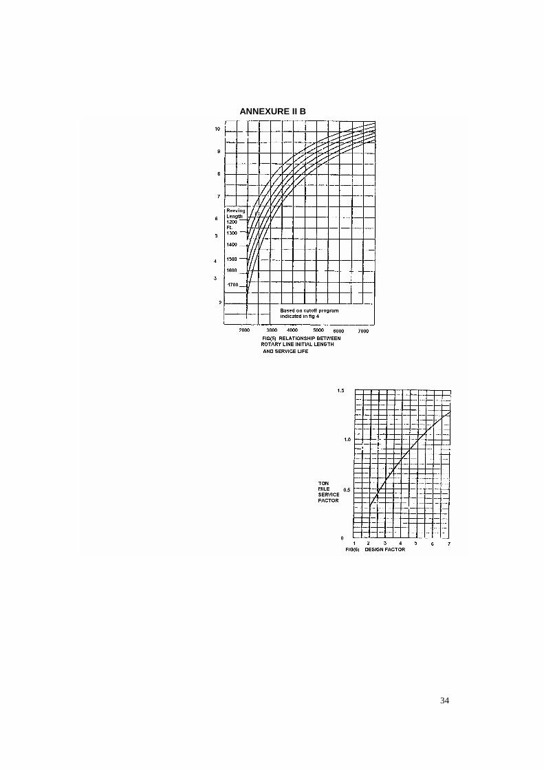
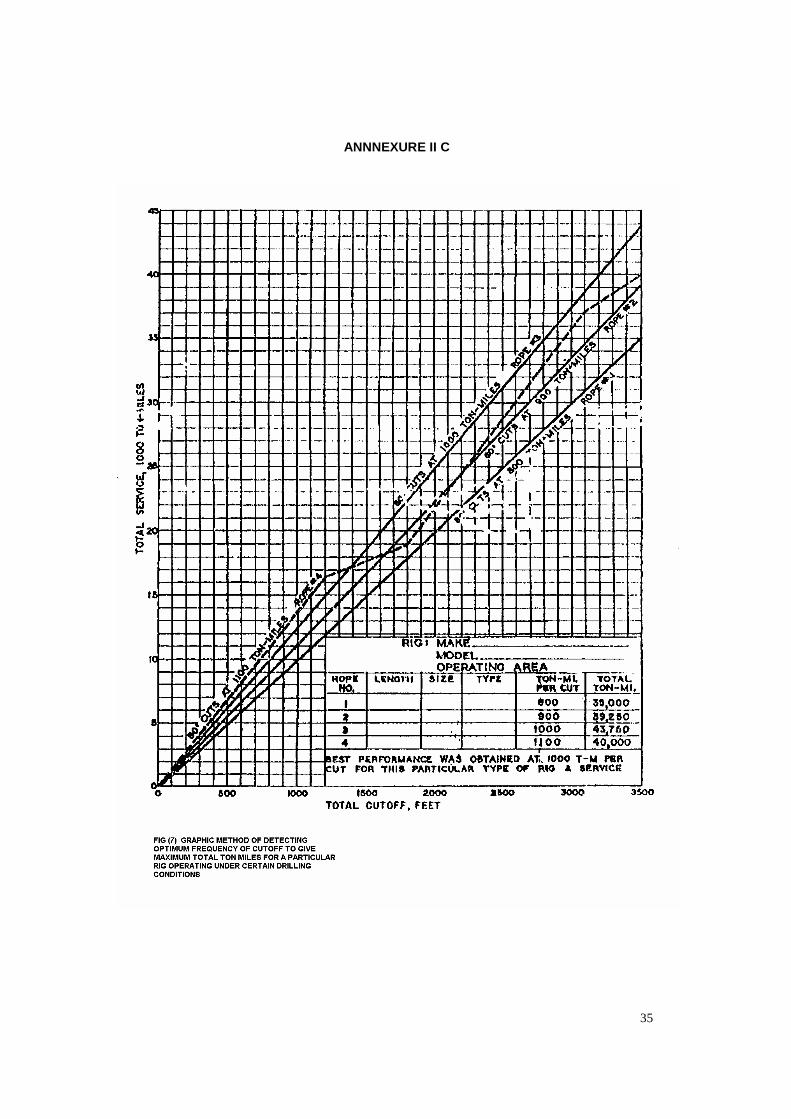
Work done by drilling lines of a well can be calculated by summing up of ton-miles for all round-trip operations (Formula a), for all drilling operations (Formula e), for all coring operations (Formula f), the ton-miles for all casing setting operations (Formula g) and for all short trip operations (Formula i). 14.7 Records Daily work done by drilling line should be recorded in the rotary drilling line service record maintained at the rig by tool pusher/ driller in charge. 15.0 SLIPPING AND CUT OFF PRACTICE FOR DRILLING LINES/ CASING LINE The service life of drilling line can be greatly increased by the use of a planned program of slipping and cut-off based upon increments of service. The sole dependence on visual inspection to determine when to slip and cut results in uneven wear, trouble with spooling (line “cutting in” on the drum), and long cut-offs, thus decreasing the service life. The general procedure in any program should be to supply an excess of drilling line over that required to string up, and to slip this excess through the system at such a rate that it is evenly worn and that the line removed by cut-off at the drum end has just reached the end of its useful life. 15.1 Service Goal A goal for line service in terms of ton-miles between cut-offs should be selected. This value can initially be determined from Fig.4 and 6 and later adjusted in accordance with experience. Fig.7 shows a graphical method of determining optimum cut-off frequency.( Figures placed in Annexure II A,B,C ) Explanation: To determine (approximately) the desirable ton-miles before the first cut-off on a new line, draw a vertical line from the derrick height to the wire line size used. Project this line horizontally to the ton-mile figure given for the type of drilling encountered 100 ton-miles less than those indicated for 1 1/8-in.and smaller lines, and at 200 ton-miles than 1¼-in. and 13/8-in. lines.
15.2 Cut-off Length. The following factors should be considered in determining a cut-off length :
i. The excess length of line which can conveniently be carried on the drum.
ii. Load-pickup points from reeving diagram.
iii. Drum diameter and crossover points on the drum.
Care should be taken to see that crossover and pickup points do not repeat. This is done by avoiding cut-off lengths which are multiples of either drum circumference, or lengths between pickup points. Successful programs have been based on cut-off lengths ranging from 30 to 150 ft. Table 4 shows a recommended length of cut-off (number of drum laps) for corresponding height of derrick and drum diameter. 15.3 Slipping Program The number of slips between cut-offs can vary considerably depending upon drilling conditions and on the length and frequency of cut-offs. This frequency can vary from one or two slips to as much as four slips between cut-offs. Slips will be more if the digging is rough, if jarring jobs occur, etc. Slipping that causes an extra layer on the drum should particularly be avoided. In slipping the line, the rope should be slipped an amount such that no part of the rope will be located for a second time in a position of severe wear. The positions of severe wear are the point of crossover on the drum and the sections in contact with the travelling and crown-block sheaves at the pickup position. The cumulative number of feet slipped between cut-offs should be equal to the recommended number of feet for ton-mile cut-off. For example, if cutting off 80 ft every 800 ton-miles. 20 ft should be slipped every 200 ton-miles, and the line cut off on the fourth slip. Example:- Let us assume : Derrick height ; 138 ft b. Wire-line size : 1¼ in. c. Drum diameter : 28 in. d. Design Factor : 3

25
Solution:- From Fig.4 determine that (for a line with a design factor of 5) the first cut-off would be made after 1200 ton-miles and additional cut-offs after each successive 1000 ton-miles. Since a design factor of 3 applies. Fig.6 indicates that these values should be multiplied by a factor of 0.58. Hence the first
cut-off should be made after 696 ton-miles and additional cut-offs after each successive 580 ton-miles. From Table 4 determine that 11½ drum laps (84 ft.) should be removed at each cut-off. Slip 21 ft. every 174 ton-miles for four times and cut off after the fourth slip. There after, slip 21 ft. every 145 ton-miles and cut- off on the fourth slip.
Table 4 1 2 3 4 5 6 7 8 9 10 11 12 13 14 15
DRUM DIAM ET ER, INCHES.
11 13 14 16 18 20 22 24 26 28 30 32 34 36
MAST HT.( FT .)
NUMBER OF DRUM L APS PER CUTOFF 151 Up 151 /2 14
/2 131/2
121 /2
111 /2
141 t o 150
13 1 /2
12 1 /2
11 1 /2
11 1 /2
11 ½
10 ½
133 t o 140
15 1 /2
14 ½
12 1 /2
11 1 /2
11 1 /8
10 1 /2
9 1 /2
120 t o 132
17 1 /2
15 1 /2
14 1 /2
12 1 /2
12 1 /2
11 1 /2
10 1 /2
9 1 /2
9 ½
91 to 119
19 1 /2
17 1 /2
14 1 /2
12 1 /2
11 1 /2
10 1 /2
9 1 /2
9 1 /2
8 ½
73 to 90 17 1 /2
14 1 /2
12 1 /2
11 ½
Up through 72
12 1 /2
11 1 /2
26
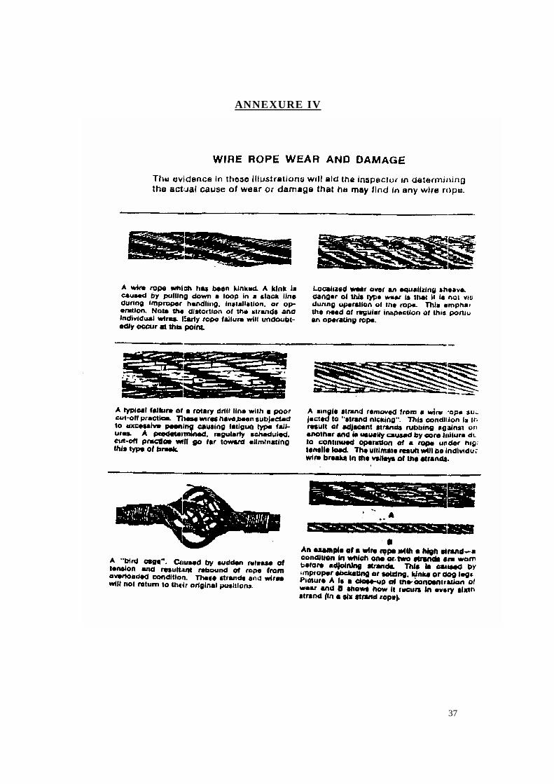
16.0 FIELD TROUBLES, CAUSES AND REMEDIAL MEASURES
All wire rope will eventually deteriorate in operation or have to be removed simply by virtue of the loads and reversals of load applied in normal service. There are, however, many condition of service or inadvertent abuse which will materially shorten the normal life of a wire rope of proper construction although it is properly applied. The following field troubles and their causes give some of the field conditions and practices which result in the premature replacement of wire rope. It should be borne in mind that in all cases the contributory causes of removal may be one or more of these practices or conditions.( Please refer Annexure for figures of various troubles) 16.1 Rope broken (all Strands or
partly). Possible Causes; Overloading, kinking, divider interference, localized wear, or rust-bound condition. Fatigue, excessive speed, slipping, or running too loosely. Concentration of vibration at dead sheave or dead-end anchor. Remedial measures; The dead-line anchorage system should be equipped with a drum and clamping device strong enough to withstand the loading, and designed to prevent damage to the wire line that would affect service over the sheaves in the system. Care should be taken to avoid kinking a wire rope since a kink can be cause for removal of the full wire rope or damaged section. Load conditions be reviewed and to be applied adequately according to strength of wire rope. 16.2. Excessive corrosion: Possible Causes; Lack of lubrication. Exposure to salt spray, corrosive gases, alkaline water, acid water, mud, or dirt. Period of inactivity without adequate protection. Remedial measures; Lubricate the rope with a good grade of lubricant which will penetrate and adhere to
the rope, and which is free from acid or alkali. 16.3 Rope damage by careless
handling in hauling to the well or location.
Possible Causes ; Rolling reel over obstructions or dropping from car, truck, or platform. The use of chains for lashing, or the use of lever against rope instead of flange. Nailing through rope to flange. Remedial measures; Refer to chapter on “Handling of Reel“ 16.4 Damage by improper socketing. Possible Causes; Improper seizing which allows slack from one or more strands to work back into rope improper method of socketing or poor workmanship in socketing, frequently shown by rope being untwisted at socket, loose or drawn. Remedial measures; The wire rope should be securely seized or clamped at the end before cutting. Measure from the end of the rope a length equal to approximately 90 % of the length of the socket basket. Seize or clamp at this point . Use as many seizings as necessary to prevent the rope from un-laying . 16.5 Kinks, dog legs, and other
distorted places Possible Causes; Kinking the rope and pulling out the loops such as in improper coiling or unreeling. Improper winding on the drum. Improper tie-down. Open-drum reels having longitudinal spokes too widely spaced. Divider interference. The addition of improperly spaced cleats to increase the drum diameter. Stressing while rope is over small sheave or obstacles. Remedial measures ; Care should be taken avoid the above referred cause for any possible damage to wire rope.

27
16.6 Damage by hooking back slack too tightly to girt.
Possible Causes; Operation of walking beam causing a bending action on wires at clamp and resulting in fatigue and cracking of wires, frequently before rope goes down into hole. Remedial measures ; The clamps used to fasten lines for dead ending should not kink, flatten or crush the rope. 16.7 Damage or failure on a fishing job. Possible Causes; Rope improperly used on a fishing job, resulting in damage or failure as a result of the nature of the work. Remedial measures ; Sudden, severe stresses are injurious to wire rope and such applications should be reduced to a minimum. Wear increases with speed, the load should be increased with diminishing the speed. 16.8 Lengthening of lay and reduction of diameter. Possible Causes ; Frequently produced by some type of overloading, such as an overload resulting in a collapse of the fiber core in swabbing lines. This may also occur in cable-tool lines as a result of concentrated pulsating or surging forces which may contribute to fiber-core collapse. Remedial measures ; Care should be taken to avoid over loading . 16.9 Premature breakage of wires. Possible Causes; Caused by frictional heat developed by pressure and slippage, regardless of drilling depth. Remedial measures ; The use of solvent may be detrimental to a wire rope. If a rope becomes covered with dirt or grit, it should be cleaned with a brush. Whenever possible, a new wire rope should be run under controlled loads and speeds for a short period after it has been installed.
This will help to adjust the rope to working conditions. Lubricate the rope with a good grade of lubricant which will penetrate and adhere to the rope, and which is free from acid or alkali. In case of failure of fibre , the reduction of diameter is observed as explained in para 16.8 16.10 Excessive wear in spots. Possible Causes; Kinks or bends in rope due to improper handling during installation or service. Divider interference : also, wear against casing or hard shells or abrasive formations in a crooked hole. Too infrequent cut-offs on working end. Remedial measures ;
i. Blocks should be strung to give a minimum of wear against the sides of sheave grooves.
ii. The reel should be set up on a substantial horizontal axis so that it is free to rotate as the rope is pulled off, and in such a position that the rope will not rub against derrick members or other obstructions while being pulled over the crown. A snatch block with a suitable size sheave should be used to hold the rope away from such obstructions.
iii. Tension should be maintained on the wire rope as it leaves the reel by restricting the reel movement. A timber or plank provides satisfactory brake action. When winding the wire rope on the drum, sufficient tension should, be kept on the rope to assure tight winding.
iv. Care should be taken to avoid kinking a wire rope.
v. Wire ropes should not be struck with any object such as a steel hammer, derrick hatchet, or crow bar which may cause un-necessary nicks or bruises. Even when a soft metal hammer is used, it should be borne in mind that a rope can be damaged by such blows. Therefore, when it is necessary to crowd wraps together, any such operation should be performed with the greatest of care; and a block of wood should be interposed between the hammer and rope.
28
16.11 Spliced rope. Possible Causes; A splice is never as good as a continuous piece of rope, and slack is liable to work back and cause irregular wear. Remedial measures ; Use of spliced rope should be restricted. 16.12 Reduction in tensile strength or damage to rope. Possible Causes; Excessive heat due to careless exposure to fire or cutting torch. Remedial measures ; Wire rope should be protected from excessive heat exposure. 16.13 Distortion of wire rope, abrasion,
broken wires in a straight line or loosened strands , rapid fatigue breaks
Possible Causes; Damage due to improperly attached clamps or wire rope clips. Remedial measures ;
i. Correct application of the clips/ clamps on wire ropes be ensured
ii. The nuts on the second and additional clips should be tightened uniformly, by giving alternately a few turns to one side and then the other .
iii. Apply a little oil on threads to allow the nuts to be drawn tighter.
iv. The nuts should be tightened at all subsequent regular inspection periods.
16.14 Wear by abrasion Possible Causes; Lack of lubrication. Slipping clamp unduly. Sandy or gritty working conditions. Rubbing against stationary object or abrasive surface. Faulty alignment. Undersized grooves and sheaves. Remedial measures ;
i. All sheaves should be proper alignment and of proper size .The fast
sheave should be line up with the center of the hoisting drum.
ii. The worn sheaves grooves cause excessive wear on the rope, these should be repaired.
iii. The condition of sheaves grooves and contour of sheave grooves should be checked periodically.
iv. Rubbing against stationary , sharp objects and abrasive surface should be avoided .
v. Greasing of sheave and pulley surfaces.
16.15 Fatigue breaks in wires. Possible Causes; Excessive vibration due to poor drilling conditions. i.e.. high speed, rope slipping concentration of vibration at dead sheave or dead-end anchor, undersized grooves and sheaves and improper selection of rope construction. Prolonged bending action over spudder sheaves, due to hard drilling conditions. Remedial measures ;
i. The clamps used to fasten lines for dead ending shall not kink, flatten or crush the rope. The rotary line dead-end tie down is equal in importance to any other part of the system. The dead-line anchorage system shall be equipped with a drum and clamping device strong enough to withstand the loading, and designed to prevent damage to the wire line that would affect service over the sheaves in the system.
ii. Care should be taken to maintain proper winding of rotary drilling lines on the draw works drum in order to avoid excessive friction which may result in the formation of martensite. Martensite may also be formed by excessive friction in worn grooves of sheaves, slippage in sheaves, or excessive friction resulting from rubbing against a derrick member.
iii. A line guide should be employed between the drum and the fast line sheave to reduce vibration and keep the drilling line from rubbing against the derrick.
16.16 Spiraling or curling. Possible Causes;

29
Allowing rope to drag or rub over pipe, sill, or any object during installation or operation. Remedial measures ;
i. It is recommended that a block with sheave diameter 16 times the nominal wire-rope diameter, or larger, be used during installation of the line.
ii. Do not allow the line to scrub against any part of a derrick or mast. A large diameter snatch block can be used to guide the line.
16.17 Excessive flattening or crushing. Possible Causes; Heavy overload, loose winding on cross winding Remedial measures ;
i. The clamps should not be too tight, it will crush the wire line.
ii. Avoid loose winding and heavy loads.
16.18 Bird-caging or core-popping. Possible Causes; Sudden unloading of line such as hitting fluid with excessive speed. Improper drilling motion or jar action. Use of sheave of too small diameter or passing line around sharp bend. Remedial measures ; Reduce shock loading by picking up and releasing loads as gently as conditions permits. Selection of proper size of sheaves and passing of rope around sharp bend to be avoided. 16.19 Whipping off of rope. Possible Causes; Running too loose. Remedial measures; Excessive high speed / jerks of draw works to be avoided. 16.20 Cutting in on drum. Possible Causes;
Loose winding on drum. Improper cut-off and moving program for rotary drilling lines. Improper or worn drum grooving or line turn back plate. Remedial measures; · Rope should be kept tightly and evenly
wound on the drums. · Slipping that causes an extra layer on
the drum should particularly be avoided . · The line should be slipped an amount
such that no part of the rope should be located for a second time in a position of severe wear.
16.21 Cleaning the wires and fittings Different types of resin with different characteristics require varying degrees of cleanliness. For some, the use of a soluble oil for cleaning wires has been found to be effective. The following cleaning procedure was used for one type of polyester resin with which over 800 tensile tests are made on ropes in sizes ¼” (6.5 mm) to 3½” (90 mm) diameter without experiencing any failure in the resin socket attachment. Thorough cleaning of the wires is required to obtain resin adhesion. Ultrasonic cleaning in recommended solvents (such as tri-chloro -ethlylene or 1-1-1 tri-chloro-ethane or other non-flammable grease cutting solvents) is the preferred method of cleaning the wires in accordance with OSHA standards. Where ultrasonic cleaning is not available, trichloroethane may be used in brush or dip-cleaning, but fresh solvent should be used for each rope end fitting, and should be discarded after use. After cleaning, the broom suitable fashion before proceeding to the next step. The use of acid to etch the wires before resin socketing is unnecessary and not recommended. Also, the use of a flux on the wires before pouring the resin should be avoided since this adversely affects bonding of the resin to the steel wires. Since there is a variation in the properties of different resins, the manufacturer’s instructions should be carefully followed.
30
17.0 DO’S AND DON’TS 1. When transporting a reel, use protective boards with slings to prevent crushing the line. 2. Do not roll the reel over faces where dirt or sand may be picked up on the line. 3. Align the reel with the dead line anchor to avoid scrubbing against steel members. 4. Check all sheaves in crown and
travelling blocks for wear and tear condition. Worn sheaves can damage drilling line.
5. When stringing up a line, use a wire
line grip (snake) with swivel to prevent transferring twist to the drilling line.
6. Avoid throwing kinks in a drilling line.
Any loops should be straightened out manually to prevent kinking.
7. Do not allow the line to scrub against
any part of a derrick or mast. A large diameter snatch block can be used to guide the line.
8. Put enough dead wraps on the
drum. Grooved drums require fewer wraps than the smooth drums.
9. Avoid striking the line with a hammer
or any instrument that could nick or bruise the wires.
10. Provide a protective covering for
the drilling line reel to protect against mud, corrosive fluids, water and wind-borne abrasives.
11. Check the fleet angle to assure that
the center of the drum is in line with the crown fast sheave. This promotes even spooling and reduces wear on the fast sheave.
12. Use turnback rollers on each side of
the drum to reduce scrubbing at those points where new layers of line are started.
13. Excessive speed is a major cause of line wear. This becomes a problem when hoisting an unloaded travelling block.
14. Shock loading occurs when a line is
suddenly loaded or unloaded. To some extent, this is unavoidable on a drilling rig. However a driller can reduce shock loads by picking up and releasing loads as gently as conditions permit.
15. When the travelling block is in the
lower or upper pickup position, those parts of the drilling line in contact with sheaves are subject to severe bending and fatigue stresses.
16. Loose drum spooling causes cutting
in of drilling line. This results in severe scrubbing wear and crushing of parts of the line.
17. Periodically, a visual inspection
should be made of drilling line as it is spooled on or off the drum. Weak places indicated by broken or worn wires or distortion of the line may be removed from the system by slipping and cutting the drilling line. Working stuck pipe or fishing operations can overload or shock load to an extent that makes inspection advisable.
18. Drilling line should be slipped three
to five times between cut-offs to move stressed parts of the line. Slipping does not move wear points on the drum.
19. Cut-off length of drilling line on
drilling rig should be carefully calculated and measured. To move wear points, cut-off length should be x + 1/4 wraps on the drum.
20. Field lubrication may become
necessary if the line looks dry. Use a lubricant recommended for wire rope.
21. We still hear about the proper way to apply wire rope clips. After initial tightening of the clips it is recommended that an occasional

31
inspection be made and the tightness of the nuts on the clip U-bolts be checked. It is even suggested that a few drops of oil on these threads will enable the maximum to tightness.
22. When stringing up, slipping, and
cutting the drilling line with the travelling block suspended by a hang-off line (a single length of wire rope to the crown block) the proper application of clips is a part of the procedure. It is generally accepted that a tie made with properly applied clips will have strength equal to 80% of the wire rope itself.
23. Nylon slings should not be used on
rigs. 24. Avoid dropping the reel , Broken or
damaged reel leads to damaged line.
25. Check the clamp on the deadline
anchor. The line must be firmly gripped to prevent slippage. If the clamp is too tight, the line will be crushed.
26. Use a line guide to dampen fast-line
whip and to assist in better spooling. 18.0 GLOSSARY 1. Fibre Core It is composed of
vegetable fibre such as manila, jute or sisal. The fibre core cushions the steel strands of the wire rope during operation.
2. Steel Core The steel core of a wire rope can be either a wire strand or a separate / Independent Wire Rope Core ( I.W.R.C.)
3. Wire Rope Lay This term describes the direction of rotation of wires and strands.
4. Galvanising To protect the wire rope from the effects of corrosion a coating of zinc is applied to individual wires.
5. Wire Rope Classification Wire rope gets its numerical classification from the number of strands and wire used in construction.
6. Seizing It means to bind the prior to cutting so that ends do not ravel out .
7. PS Plow Steel 8. IPS Improved Plow Steel 9. EIPS Extra Improved Plow Steel 10. RL Right Lay 11. LL Left Lay 12. FC Fibre Core 13. FW = Filler wire construction 14. PF= Performed 15. NPF= Non performed 16. IWRC= Independent Wire Rope Core 19.0 REFERENCES 1. API Recommended Practice 9 B (RP
9B), 1993 2. Lessons in Rotary Drilling Of IADC 3. Product Catalogue of M/S Usha
Martin International 4. Drilling Operation Manual
32
Annexure I
TYPICAL SIZES AND CONSTRUCTION OF WIRE ROPE ( API 9B)
SERVICE AND WELL DEPTH
WIRE ROPE DIAMETER (INCH.)
WIRE ROPE DESCRIPTION
SAND LINES Shallow Intermediate Deep
¼ to ½ incl. ½ to 9/16 9/16 to 5/16
6 x 7 PS or IPS bright or galv. PF or NPF , RL, FC
DRILLING LINES Coring and slim Lines Shallow Intermediate
7/8 to 1 1 to 1/8
6 x 19 seale or 6 x 25 FW PS or IPS ,PF or NPF , RL, IWRC or FC 6 x 19 Seale or 6 x 25 FW, EIPS, PF, RL or IWRC
DRILLING LINES (1) Large Rotary Rigs Shallow Intermediate Deep
1 to 1 1/8 1 1/8 to 1 ¼ 1 ¼ to 2
6 x 19 seale or 6 x 21 FW PS or IPS ,PF or NPF , RL, IWRC or FC 6 x 19 Seale or 6 x 21 FW, EIPS, PF, IWRC
WINCH LINES Heavy duty
5/8 to 7/8
6 x 31 seale or 6 x 21 FW, IPS, PF,RL,IWRC or FC 6 x 31 Seale or 6 x 21 FW , EIPS,PF,RL, Iwrc
MOORING LINES 7/8 to 2 incl. 1 3/8 to 3 ½ incl. 3 ¾ to 5 incl.
6 x 19 IPS, PF ,galv, IWRC or 6 x 19 EIPS , PF, IWRC 6 x 37 IPS, PF, galv., IWRC or 6 x 37 EIPS, PF, IWRC 6 x 61 IPS, PF, galv., IWRC or 6 x 61 EIPS, PF, IWRC
MAST RAISING LINES
1 3/8 and smaller 1 ½ and larger
6 x 25 FW,IPS or EIPS, PF, IWRC 6 x 37 IPS or EIPS, PF, IWRC
(1) For Drilling lines 1 3/8 inches and larger some manufacturers recommend wire ropes type 6 x
26 Warrington seale IPS or EIPS, IWRC which have better fatigue resistance for a good strain resistance.
33
ANNEXURE II A
34
ANNEXURE II B
35
ANNNEXURE II C
36
ANNEXURE III
37
ANNEXURE IV
<< Back Home Next >>