babcock valves - product rangebabcockvalves.com/en/wp-content/uploads/2017/05/gate... ·...
TRANSCRIPT

GATEVALVESPRODUCT RANGE

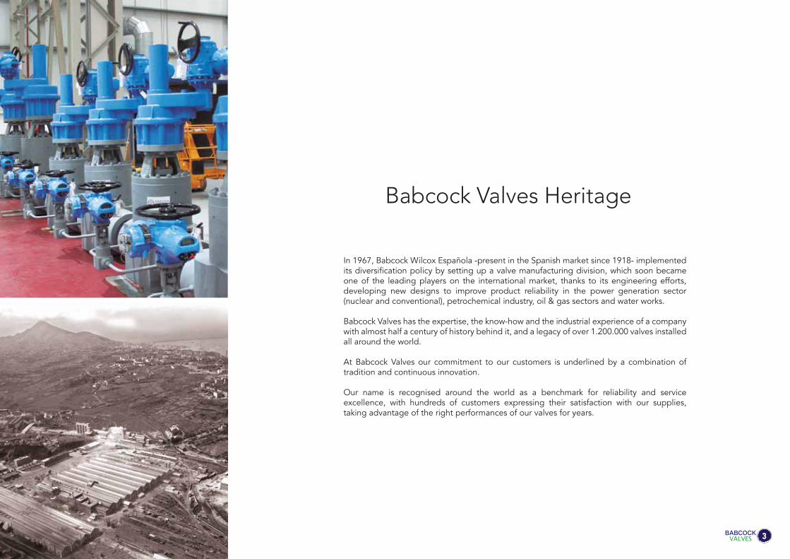
In 1967, Babcock Wilcox Española -present in the Spanish market since 1918- implemented its diversification policy by setting up a valve manufacturing division, which soon became one of the leading players on the international market, thanks to its engineering efforts, developing new designs to improve product reliability in the power generation sector (nuclear and conventional), petrochemical industry, oil & gas sectors and water works.
Babcock Valves has the expertise, the know-how and the industrial experience of a company with almost half a century of history behind it, and a legacy of over 1.200.000 valves installed all around the world.
At Babcock Valves our commitment to our customers is underlined by a combination of tradition and continuous innovation.
Our name is recognised around the world as a benchmark for reliability and serviceexcellence, with hundreds of customers expressing their satisfaction with our supplies, taking advantage of the right performances of our valves for years.
Babcock Valves Heritage
3


To guarantee high levels of quality for all of our products, our Quality Assurance Department implements a rigorous control and testing system throughout the manufacturing process. Moreover, Babcock Valves keeps an operational quality control and assurance manual that enables us to maintain optimum quality levels.
All of our products are tested during the design phase and after assembly, prior to shipment. Testing includes cryogenic tests, hot cycle tests, multi-axis vibration tests, aging tests, flow and pressure tests, seismic resistance tests, valve hammer-impact tests, actuator tests and others.
Our valves are designed, manufactured and inspected, in accordance with the mostrelevant international standards, such as:
API (American Petroleum Institute)
ANSI (American National Standards Institute)
AWWA (American Water Works Association)
DIN (Deutsche Norm)
JIS (Japanese Industrial Standards)
BS (British Standards)
AFNOR (Association Française de Normalisation)
MSS (Manufacturers Standardization Society)
ISO (International Standards Organization)
UNE (Spanish Standard)
EAC Eurasian Conformity
Quality & Certifications
5


Double Disc Valves
Babcock’s Gate ValvesProduct Range
Through Conduit ValvesWedge Gate Valves Parallel Slide Disc Valves
7

WEDGEGATEVALVESPRODUCT RANGE

Wedge Gate ValvesComplying with the requirements of the industrial sector.
Code: 22
Type: Wedge GateBonnet: BoltedHandling: OS&YSizes: 1/2” - 72”ANSI Class: 150-2500
Code: 25
Type: Wedge GateBonnet: Pressure SealHandling: OS&YSizes: 2” - 48”ANSI Class: 600-4500
Code: 84
Type: Wedge Gate CryogenicBonnet: BoltedHandling: OS&YSizes: 2” - 48”ANSI Class: 150-900
Wedge gate valves are commonly supplied with solid wedge up to 2” size and with flexible wedge for larger sizes. The latter design consists of two independent and flexible wedge halves, that allow a relative movement to accommodate changes in the body seat angles. The result is a valve with a high pressure sealing performance, with optimum results at low differential pressures, meeting industrial valve requirements, moved toward larger sizes and higher pressures and temperatures.
Our utmost care when machining and lapping wedge and seats, and the flexible wedge design for sizes beyond 2”, assure valve tightness on both sides regardless of the operating pressure.
Carbon steel, alloy steel, stainless steel and other valve materials may be selected depen-ding on the fluid and pressure and temperature conditions following ASME B16.34 standard.
The standard wedge gate valves shall be outside screw and yoke, non-rotating stem, T-head stem-wedge connection and welded / threaded / integral seats. The valve can be manually operated or by means of an electric, pneumatic or hydraulic actuator.
The most common standards used are:
Design: ASME B16.34, API 600 for cast valves and API 602 for small size forged valves.
Testing: API 598 and ASME B16.34.
9

DOUBLEDISCGATEVALVESPRODUCT RANGE
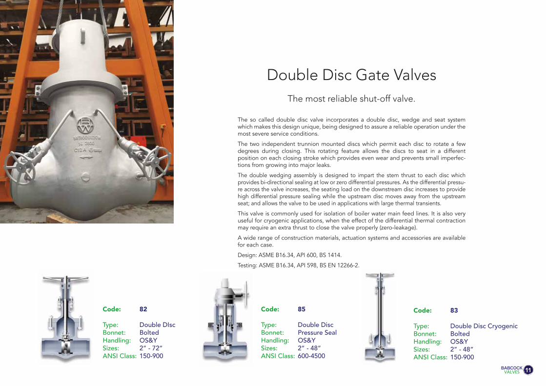
Double Disc Gate ValvesThe most reliable shut-off valve.
Code: 82
Type: Double DIscBonnet: BoltedHandling: OS&YSizes: 2” - 72”ANSI Class: 150-900
Code: 85
Type: Double DiscBonnet: Pressure SealHandling: OS&YSizes: 2” - 48”ANSI Class: 600-4500
Code: 83
Type: Double Disc CryogenicBonnet: BoltedHandling: OS&YSizes: 2” - 48”ANSI Class: 150-900
The so called double disc valve incorporates a double disc, wedge and seat system which makes this design unique, being designed to assure a reliable operation under the most severe service conditions.
The two independent trunnion mounted discs which permit each disc to rotate a few degrees during closing. This rotating feature allows the discs to seat in a different position on each closing stroke which provides even wear and prevents small imperfec-tions from growing into major leaks.
The double wedging assembly is designed to impart the stem thrust to each disc which provides bi-directional sealing at low or zero differential pressures. As the differential pressu-re across the valve increases, the seating load on the downstream disc increases to provide high differential pressure sealing while the upstream disc moves away from the upstream seat; and allows the valve to be used in applications with large thermal transients.
This valve is commonly used for isolation of boiler water main feed lines. It is also very useful for cryogenic applications, when the effect of the differential thermal contraction may require an extra thrust to close the valve properly (zero-leakage).
A wide range of construction materials, actuation systems and accessories are available for each case.
Design: ASME B16.34, API 600, BS 1414.
Testing: ASME B16.34, API 598, BS EN 12266-2.
11

Technical Advantages of the Double Disc Wedge Assembly
The double disc gate valve has been designed to assure reliable operation under the most severe service condi-tions. Due to the special configuration and geometry of the upper wedge inclined face, any possibility of locking the disc in closed position is eliminated, even when closed quickly or subjected to severe thermal transients.
RELIABLE OPERATION
The wedge assembly is designed to impart sufficient thrust to each disc to maintain low pressure sealing. As the differential pressure across the disc increases, the seating load also increases, thus providing a tight seal throughout the entire range of operating differential pressures. Since the discs are independent of each other and the design is symmetrical, positive sealing can be maintained in either direction.
LOW PRESSURE SEALING
The tight seal is guaranteed even when the valve seats have become out of parallel due to body distortion, due to the uniform distribution of the sealing pressures allowed by the exclusive wedge design.
UNIFORM DISTRIBUTIONOF SEALING PRESSURE
12

Babcock’s double disc wedge system permits rapid closure without seat distortion. Internal moving parts decelerate independently of each other with the result that inertial forces are dissipated in a series of impacts over a period of time. The largest force is transmitted directly to the bottom of the valve body on a non-sealing surface. Forces transmi-tted directly to the seats a small percentage of the seats are a small per centage of the total inertial forces. This is a distinct advantage over valve designs in which the total inertial force is absorbed directly by the seating surface.
RAPID CLOSURE
The incorporation of a unique revolving disc feature assures maximum seat life. The two independent discs, during each closing stroke and immediately prior to the disc seating, rotate a few degrees in the plane of the seats. This rotating action forces the disc to seat in a different position on each stroke, equalizing wear on the seats and the discs. This movement of the discs creates a lapping effect whenever the valve is operated, removing particles from the sealing surfaces before they can become wedged between the seats and the disc and cause damage.
UNIFORM SEAT WEAR
The four piece double disc wedge assembly can neither be incorrectly assembled nor become disengaged while in service. No special fitting at site is required for maintenance. The repair of minor seat or disc damage is greatly simplified because the seats and discs can be lapped independently of each other. Disassembly and maintenance can be accomplished without special tools or elaborate rigging.
EASY MAINTENANCE

PARALLELSLIDEGATEVALVESPRODUCT RANGE

The parallel slide gate valve is an alternative to double disc valves, having two discs but only one wedge instead of two. The discs are in permanent contact with the seat rings, getting a tight seal due to the horizontal inconel spring located in between and without the wedging system help.
The complete guiding system is precisely machined for ensuring a smooth open and close operations and eliminating vibrations.
The parallel slide gate valve is recommended to be used for clean fluids and steam applica-tions and for medium or high pressure service.
A wide range of construction materials, actuation systems and accessories are available for each case.
Parallel Slide Gate Valves
Code: 87
Type: Parallel SlideBonnet: BoltedHandling: OS&YSizes: 2” - 48”ANSI Class: 150-900
Code: 89
Type: Parallel SlideBonnet: Pressure SealHandling: OS&YSizes: 2” - 48”ANSI Class: 600-4500
Code: 86
Type: Parallel Slide with follower eyeBonnet: Pressure SealHandling: OS&YSizes: 2” - 48”ANSI Class: 600-4500
Code: 88
Type: Parallel Slide with follower eyeBonnet: BoltedHandling: OS&YSizes: 2” - 60”ANSI Class: 150-900
15
Reliability with low operating forces

Exploded view of the parallel slide system, showing all the parts involved in this assembly.

Follower eye for very laminar flow is available on request. It avoids any turbulences and minimizes the pressu-re drop.
CODE 86 - 88:
Parallel Slide Design Main Features
• Two discs and just one wedge design gate valve.
• Parallel slide gate valve provides a smooth flow path between seats.
• This design of gate valve is commonly used for clean fluids and steam applications.
• System pressure is used to provide isolation. The closing is only made over one of the seats. The higher pressure in the system, the better closing tightness.
• The discs have a certain movement to assure its right alignment with the seats contact faces when closing (seal is established on outlet seat face only), avoiding any mechanical stress.
• The inconel spring located between both discs, provides initial seating force. Once the discs are in the right position, no additional torque is necessary to achieve a positive seal.
• Torque requirement is lower than other gate valves as wedge type because needs lower operative forces.
• The wiping action of the discs over seats while the valve is operating removes debris and prevents premature wear of the components. A long life service is guaranteed by means of hardening seats and discs with an extra hard material as Stellite 6, Tribaloy or others.
• Parallel slide system avoids jamming related to cooling down of the pipeline.
• A wide range of construction materials, actuation systems and accessories are available for each case.
17

STANDARD BOLTED BONNET GASKETS
Class 150Detail forFLAT GASKET
Class 300Detail forSPIRAL WOUND GASKET
Class 600Detailfor RTJ GASKET
BOLTEDBONNETThe most common connection between valve body and bonnet for ASME ratings up to 600 is with bolts and is usually called Bolted Bonnet. Under demand, it can be also used for high pressure applications up to class 2500.
The Babcock’s strong designs and a precision machining of bodies and bonnets shall guarantee the best performances of the valves during opera-tion.
The right sealing between body and bonnet is made by designing a more than sufficient type and number of bolts, and selecting the best gasket for each service.
There are different joint / gasket designs for each applicable ASME rating. A flat oval gasket is normally used for low pressure (class 150) and a spiral wound gasket for intermediate pressures (class 300) and high pressure (class 600). Other type of joints as corrugated or ring type are also available under demand.
NOTE:
For Class 900 and superior, the Bolted Bonnet gasket used is RTJ.


Our Valves can adopt pressure seal bonnets to allow high pressure service, typically in excess of 15 Mpa (2250 psi).
The main feature about the pressure seal bonnet is that the body-bonnet joints seals improves as the internal pressure in the valve increases, compared to other constructions where the increase in internal pressure tends to create leaks in the body-bonnet joint.
The basic operation of this kind of valve, where the seal is achieved from the pressure exerted by the fluid flowing trough the valve, is as follows:
Internal pressure forces the bonnet upwards against the gasket, creating forces in the contact areas between the gasket and the bonnet and between the gasket and the body.
Leaks most commonly arise at the contact surface between the gasket and the body. The area where the body is in contact with the joint is covered by stainless steel, improving surface’s quality and avoiding corro-sion issues.
Gaskets are carefully designed to produce a tight seal regardless of the line conditions, that can be easily dismantled for maintenance operations.
PRESSURESEALBONNET
BonnetBody
Gasket
Fig. 4 - Angle 45ºFig. 3 - Angle 25º
Fig. 2
Gasket
Fig. 1Forces making the seal
Gasket

GENERAL DESCRIPTION
The basic operation of this kind of valve, where the seal is achieved from the pressure exerted by the fluid flowing through the valve, is as follows.
Internal pressure forces the bonnet upwards against the gasket creating forces in the areas of contact between the gasket and the bonnet (wedge shaped area). and between the gasket and the body (valve passage area). See (Fig. 1 ). The quality of the seal between the surfaces depends upon two basic considerations, these being the surface quality of the areas in contact, and the degree of force (load per unit area) which holds them together.
It is easier to achieve the seal from the two gasket surfaces where a seal is made (gasket-bonnet and gasket-body) in the gasket bonnet contact area, in comparison to the larger component of the force exerted by the pressure inside, and it is more than sufficient to provi-de a tight seal.
Leaks most commonly arise at the contact surface between the gasket and the body. The .area where the body is in contact with the joint (Fig. 2) is covered with stainless steel, and this improves surface quality and avoids corrosion problems. The force actuating between the contact joint body surfaces is the horizontal component of force perpendicular to the contact surfaces between the bevelled surfaces of the joint and bonnet. The efficiency of the seal between the gasket and body is determined basically by the gasket angle, which in turn determines the horizontal force component that will act upon them. The smaller the gasket angle, the greater the horizontal component is, and hence, the harper the angle on the bevelled surface, the greater the horizontal component, and the better the seal.
A gasket designed with a 25° angle (Fig. 3) will turn into radial force, a greater component of the force exerted by the pressure from the line on the bonnet, than a gasket designed with an angle of 30° 45° (Fig.4). Moreover, in order to achieve large unitary loads, the surface upon which the force is exerted may be reduced, with checks being performed to ensure that the surface is sufficient to support the load without cracking.
When a pressure seal joint is required to seal over a large range of pressures, there may be difficulties. A gasket which is sufficiently small so as to seal under a pressure of 500 psi. may not support 2.500 psi. A way to overcome this problem is to design the gasket bonnet contact surfaces to have a difference of one degree between them (Fig. 5). Before the gasket is tightened, only its edge is in contact with the bonnet (Fig. 6). Under pressure, one part of the gasket will deform and enter into contact with the bonnet(Fig. 7).
A careful design of the gasket pressure seal angle will prevent those more serious difficulties found with large angle gaskets (30°-45°). With a narrow gasket angle (25°), a tight seal can be achieved by applying little pressure, and once the seal has been made, it will stay tight regardless of line conditions. Certain tests performed with narrower gaskets (15°-20°), showed that the seal became so tight that it was impossible to remove the gasket. A gasket of approxima-tely 25° is found to produce a seal that can be easily dismantled.
Body
Bonnet
Gasket
Fig. 6
Body Bonnet
1º
Gasket
Fig. 5
Body
Line pressure
Bonnet
Gasket
Fig. 7

15.
11.
3. 22.
128.
125.
5.
2.193.
13. 4.
7.
1.
134.
6.
111.
Gate Pressure SealValve Main Parts
Available both in cast and forged steel,it has been designed to meet all the requi-rements of ASME, API and British Standards.
The body-bonnet connection is made by a pressure seal gasket. Its pre-stress condi-tion is achieved by means of bolts screwed to the bonnet flange.
Ends are normally butwelding although they can be also flanged on request.
All bodies are provided with integrally cast bosses, located and sized in accordance with ASME B16.34, which allow the provi-sion of drain and by-pass connections, supplied on request.
Double DiscFour internal guides keep the discs assembly in place, enabling operation of the valve with stem in both vertical and horizontal positions.
Two internal bosses in the lower part of the body are machined to create the mechanical stop of the lower wedge.
1. BODY
Usually constructed in the same materials as the body, being designed so that the wall thickness always exceeds the require-ment of API 600.
A back seat bush (13.) is fitted inside the bonnet lower cavity, to provide a closure when de valve is fully opened. This permits the valve to be repacked while in service.
The bonnet has a deep stuffing box in which packing rings are placed.
Stuffing box is designed with sufficient space to allow lantern ring to be fitted.
2. BONNET
Separate rigid yoke provided to withstand the thrust of the actuator. Large windows allow easy access and ventilation of the packing area. The yoke is connected to the body by a two piece clamping ring (193.) an four clamp bolts. This connection is very solid and enables easy maintenance at site.
The upper part of the yoke is suitably machined to house the yoke sleeve (11.).
The yoke is usually made of cast carbon steel regardless the type of body material, unless otherwise required by the client.
3. YOKE
Constructed in stainless steel, machined from solid bar stock. The single piece stem in connected to the wedge by a tee connection.
A conical shoulder is also provided to ensure effective and tight seal backseat which allows the stuffing box to be replaced with the valve in service. The stem dimen-sions conform to API 600. Connection stem-wedge also meets the requirements of API 600. Pull test has been carried out to verify the design. Special care is taken in the machining of the stem, including the final polishing of the travelling area (contact with the stuffing box). This allows a low-friction surface and a superior corrosion resistance.
Double DiscConstructed in stainless steel, machined from solid bar stock. The simp le piece stem in threaded in the upper wedge.
4. STEM
The gland studs are of the eyebolt type, which can be swing outwards for ease of gland repacking.
22. / 128. GLAND BOLTS AND NUTS
They are supplied in forged stainless steel, hardfaced with Stellite-6 (2 mm of minimum thickness). Seat rings are renewable, normally welded to the body.
Sealing contact surfaces, are lapped for a perfect tight seal. Controlled hardness differentials are maintained between the wedge discs and the seat rings, as requi-red by API 600 Std.
6. SEAT RINGS
The wedge is normally constructed in forged stainless steel for diameters up to 3”, and in cast steel for larger sizes.
Wedge is commonly flexible, though it can be also solid. Guides are carefully machi-ned for a smooth sliding in the body cast-in guides.
Contact faces are overlayed with stellite-6 (2 mm of. minimum. thickness).
7. WEDGE
They are supplied in two separate self aligning pieces, to ensure uniform pressu-re is effected during tightening of the packing.
The upper part of the gland, which comes in contact with the gland flange, is spheri-cal in shape.
The gland flange is made of carbon steel but, upon request, other materials can be supplied.
5. / 125. GLANDBUSHING AND GLAND
FLANGE
*Further information in case Double Disc Gate Valve.

Designed sufficiently resistant to withstand the forces transmitted by the bonnet screws (111).
The bonnet retainer is normally made of the same material as the body, but it can be constructed in any other material on request. It is machined to match exactly with the body, what guarantees a perfect alignment of the unit.
134. BONNET RETAINER
The disc retainers are made of the same material than the body. They are firmly connected to the upper wedge and keep the discs in place while allowing their revol-ving feature.
The system of Stem, Discs, Upper Wedge and Disc retainers are crossed by a Wedge Pin (198) of Stainless Steel, connected by two nuts (129 A) and cotter pins (198 A).
80. DISC RETAINERS
17.132.
133.
5.
68.
The connection between body and yoke is created by means of a bipartite clamping ring. The internal connection between the clamp, body and yoke is conical, assuring a perfect tightening.
193. YOKE CLAMPIt is made normally of the same material as the body, and constructed in four pieces, called segments. The segments are sized to minimize the gap among them.
The segmental ring supports all the forces transmitted from the bonnet through the spacer ring. It is calculated to withstand all the force without cracking.
133. GASKET RETAINER
Made of a single piece coverting the upper part of the pressure seal gasket. It is norma-lly manufactured in the same material as the body.
132. SPACER RING
The handwheel can be supplied either in cast construction of fabricated from steel tube.
The handwheel is designed to allow easy operation of the valve. Other types of control are available and, in some cases, are indispen-sable for a good operation, for instance:
• Chain wheel• Gear operator• Hammer handwheel• Geared hammer handwheel• Electric actuator• Electro-hydraulic actuator• Pneumatic actuator
15. HANDWHEEL
Packing is made of an adequate number of preformed rings.
For general applicatios high grade graphite material is supplied, using compressed rings in the center and braided anti-extrusion rings on top and bottom. Graphite is selec-ted of an approved quality.
Other types of packing are also available for particular services.
68. PACKING
The pressure seal gaskets are usually supplied of compressed graphite, bordered on the upper and lower edges with braided filaments of graphite and Inconel.
Gaskets can also be made in stainless steel.
17. PRESSURE SEAL GASKET
Designed to permit removal from the bonnet or yoke while the valve is in service.
The yoke bushing assembly is mounted in ball bearings. It is normally made of cast aluminium bronze, having high resistance to wear and high melting point. Other materials such as Ni-resist can be supplied on request.
11. YOKE SLEEVE
The back seat can be supplied as a threaded stainless steel bush, welded to the bonnet or of integral type. It can be hardfaced with Stellite-6 or orther materials as required.
This seat allows the valve to be repacked under pressure.
13. BACK SEAT
The two forged discs are made of the same material than the body, and the seating areas are hardfaced with 2 mm minimum thickness of Stellite-6.
9. DISCS
Double Disc
23
9.
7S.129A.
198./198A.
56.
80.
7 I .
The wedges ares constructed in forged or cast steel of the same material than the body. The contact surfaces are hardfaced with Stellite-6. The special geometry of these wedges has been designed so that they cannot became disengaged while they are sliding. The wedges impart thrust to the discs which move towards the seat rings (6) assuring a tight seal.
Two wedge springs (56) are located in the cavities between the upper and lower wedges, in order to absorb the inertial forces and permit a soft contact of the sliding inclined part of the wedges.
7S. / 7 I . UPPER & LOWER WEDGES
111.

THROUGH-CONDUITGATEVALVESPRODUCT RANGE
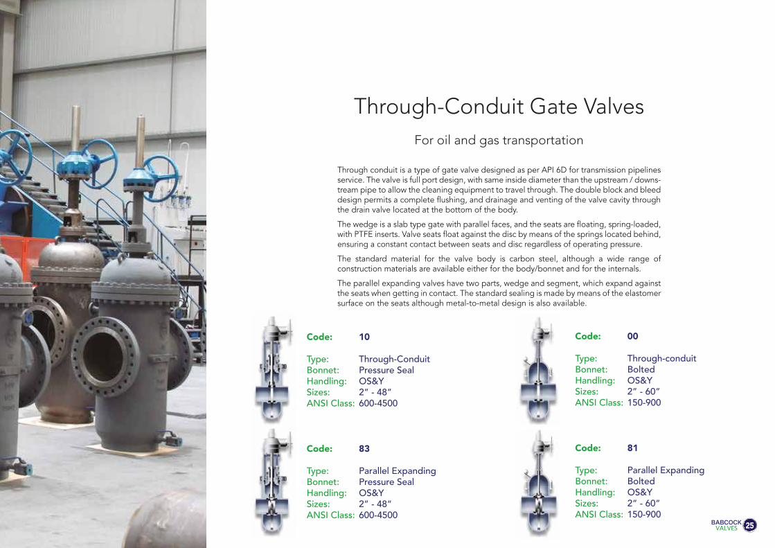
Code: 83
Type: Parallel ExpandingBonnet: Pressure SealHandling: OS&YSizes: 2” - 48”ANSI Class: 600-4500
Code: 81
Type: Parallel ExpandingBonnet: BoltedHandling: OS&YSizes: 2” - 60”ANSI Class: 150-900
Code: 10
Type: Through-ConduitBonnet: Pressure SealHandling: OS&YSizes: 2” - 48”ANSI Class: 600-4500
Code: 00
Type: Through-conduitBonnet: BoltedHandling: OS&YSizes: 2” - 60”ANSI Class: 150-900
Through conduit is a type of gate valve designed as per API 6D for transmission pipelines service. The valve is full port design, with same inside diameter than the upstream / downs-tream pipe to allow the cleaning equipment to travel through. The double block and bleed design permits a complete flushing, and drainage and venting of the valve cavity through the drain valve located at the bottom of the body.
The wedge is a slab type gate with parallel faces, and the seats are floating, spring-loaded, with PTFE inserts. Valve seats float against the disc by means of the springs located behind, ensuring a constant contact between seats and disc regardless of operating pressure.
The standard material for the valve body is carbon steel, although a wide range of construction materials are available either for the body/bonnet and for the internals.
The parallel expanding valves have two parts, wedge and segment, which expand against the seats when getting in contact. The standard sealing is made by means of the elastomer surface on the seats although metal-to-metal design is also available.
Through-Conduit Gate Valves
25
For oil and gas transportation
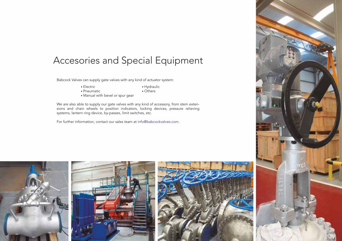
Accesories and Special Equipment
Babcock Valves can supply gate valves with any kind of actuator system:
• Electric • Hydraulic • Pneumatic • Others • Manual with bevel or spur gear
We are also able to supply our gate valves with any kind of accessory, from stem exten-sions and chain wheels to position indicators, locking devices, pressure relieving systems, lantern ring device, by-passes, limit switches, etc. For further information, contact our sales team at [email protected].

Overpressure protection device Handwheel with chain
Lantern ring Live loading packing Balance hole
FLOWFLOW
Bypass
Limit microswitches
Horizontalspur gearing
Stem extension with floor stand and universal joint
Dillatationcompensating device
27

Reliability. One world. A meaningful philosophy.
We have had this concept in mind since our inception in 1967, as the valve division of Babcock Wilcox Española. We have always understood that the world’s leading industries cannot stop operating due to a failed element in their production systems.
That’s why we design our valves to last longer, and to be problem-free: so you can forget about them. Because we can imagine the consequences should it be necessary to take a water plant offline, or a gas pipe, due to a technical fault. Or the consequences of any downtime for the power generation industry.
This is why we believe we are still trusted by so many of our initial customers, and the reason why we have over 1.200.000 valves installed in leading companies
Each day, an army of Babcock valves works silently and tirelesslyfor many of the industries that really move our world.
1.200.000 different valves.A single philosophy.
www.babcockvalves.com
Babcock Valves S.A.P.E. Abra Industrial, Parcela 1.5.6
48530 Ortuella-Bizkaia (Spain)Phone: (+34) 944 536 423
Fax (+34) 944 535 [email protected]
Our valves are designed, manufactured and inspected, in accordance with the most relevant international standards, such as:
API (American Petroleum Institute)ANSI (American National Standards Institute) AWWA (American Water Works Association) DIN (Deutsche Norm)JIS (Japanese Industrial Standards)BS (British Standards)AFNOR (Association Française de Normalisation) MSS (Manufacturers Standardization Society) ISO (International Standards Organization) UNE (Una Normativa Española)
Edic
ión:
Abr
il 20
17
nearest airport: Bilbao 25 Km.
nearest seaport: Bilbao 6 Km.
around the world. We are mainly present in the following sectors: Power Generation (Nuclear and Conventional), Petrochemical Industry, Oil & Gas, Chemical, Fertilizer, at water treatment plants, etc. Our constant focus on quality is the foundation of our work. Our position as leaders in our sector is backed up by our Design Department that, together with the R+D+I centre, provides solutions to all of our customers’ requirements. Our highly qualified workforce constantly strives for improvement and maintains a service ethos in meeting our customers’ needs.
This brochure contains the most representative items in our range of valves. However, modern techniques and customer requirements continuously impose material and design challenges, and we can therefore work to any specifications not covered in this catalogue.