b2900a series precision source/measure unit
TRANSCRIPT

P
a
g
e
Find us at www.keysight.com Page 1
B2900A Series Precision Source/Measure Unit

P
a
g
e
Find us at www.keysight.com Page 2
Innovative SMU Provides Superior Performance and Rapid Measurement Results
Single view
Dual View
Roll View
The Keysight B2900A Series of Precision Source/Measure
Units are compact and cost-effective bench-top
Source/Measure Units (SMUs) with the capability to
source and measure both voltage and current. These
capabilities make the B2900A Series ideal for a wide
variety of IV (current versus voltage) measurement tasks
that require both high resolution and accuracy.
The B2900A Series provide best-in-class performance for
a modest price. They have broad voltage (±210 V) and
current (± 3 A DC and ±10.5 A pulsed) sourcing capability,
excellent precision (minimum 10 fA/100 nV sourcing and
measuring resolution) and possess a superior color LCD
graphical user interface (GUI). In addition, several task-
based viewing modes dramatically improve productivity for
test, debug and characterization.
The B2900A Series offers unmatched measurement
throughput and supports conventional SMU SCPI
commands for easy test code migration. These features
improve efficiency and lower the cost of ownership when
integrating the SMUs into systems for production test.
The B2900A Series consists of four models, the B2901A,
B2902A, B2911A and B2912A, differentiated through their
available features (number of digits displayed,
measurement resolution, minimum timing interval,
supported viewing modes, etc.) and by the number of
SMU channels (one or two) they contain. This makes it
easy to select the exact price/performance point you
require to meet your testing needs.
Feature Benefit
Integrated 4-quadrant sourcing and measuring
capabilities
Easily and accurately measure current and voltage using a single
instrument without the need to manually change any connections
Measurement range: ±210 V, ±3 A (DC), ±10.5 A
(pulsed)
A single SMU product covers both high voltage and high current
measurement needs, allowing for more standardization and
simplifying inventory and support concerns.
Source and measurement resolution down to 10 fA
and 100 nV
Can make low-level measurements using a low-cost bench-top
SMU that were previously only possible using a more expensive
semiconductor device analyzer.
User-friendly front panel GUI with 4.3 inch color
LCD display supports both graphical and numerical
view modes
Can quickly and easily perform measurements and display data on
the front panel, thereby greatly speeding up interactive test,
characterization and debug operations.
10 microsecond digitizing capability Can capture low frequency phenomena in addition to DC
characteristics
PC-based control software Can make measurements remotely from a PC without the need to
program.
Supports both conventional and default SCPI
commands
Conventional SCPI commands provide some compatibility with
older SMU code (such as Keithley 2400 series) to minimize code
conversion work. Default SCPI commands support advanced
B2900A Series features
Small form factor with USB2.0, LAN, GPIB and
digital I/O interfaces Easy integration into rack and stack systems.

P
a
g
e
Find us at www.keysight.com Page 3
The Best SMU Solution for a Broad Range of IV Measurements
Keysight B2900A Series Precision Source/Measure Unit
SMUs are popular and widespread instruments for performing IV measurements in many different fields
and applications due to their integrated voltage and current sourcing and measurement capabilities. The
Keysight B2900A Series provides superior performance and usability at a very reasonable price. In
addition, the Keysight B2900A Series supports many functions to speed up production test and increase
throughput. The versatile measurement capabilities of the B2900A Series SMUs make them an ideal
choice for a variety of IV measurements such as semiconductor test, active/passive component test and
general electronic device and material characterization.
The B2900A Series has a broad application range that spans uses from R&D and education to industrial
development, production test and automated manufacturing. Moreover, they work equally well as either
standalone or system components.
Testing semiconductors, discrete and passive components
Diodes, laser diodes, LEDs
Photodetectors, sensors
Field effect transistors (FETs), bipolar junction
transistors (BJTs)
ICs (analog ICs, RFICs, MMICs, etc)
Resistor, varistor, thermistors, switches
Testing precision electronics and green energy devices
Photovoltaic cells
Power transistors, power devices
Battery
Automotive
Medical instruments
Power and DC bias source for circuit test
Research and education
New material investigations
Nano devices characterization (e.g. CNT)
Giant magnetic resistance (GMR)
Organic devices
Any precise voltage/current source and
measurement
Application literature is available on the Keysight
web site. For more information please visit
www.keysight.com/find/precisionSMU

P
a
g
e
Find us at www.keysight.com Page 4
Integrated Source and Measurement Capabilities Simplify Difficult IV Measurement Tasks
The Keysight B2900A Series reduces measurement complexity
Performing IV measurements with conventional
instruments such as voltage/current sources,
arbitrary waveform generators (AWGs), switches,
and voltage/current meters is complicated and
confusing. It requires deep technical knowledge of
both the measurement technique and the
instrumentation to perform an accurate
measurement.
The Keysight B2900A SMU integrates many
different source and measurement capabilities into
one compact form factor. It can operate as a
seamless 4-quadrant precision voltage/current
source, an electrical load, an accurate
voltage/current meter, a pulse generator and an
AWG. Its versatile all-in-one integrated source and
measurement capabilities allow it to perform a wide
variety of measurements from DC to low frequency
AC without the need to change connections or use
additional equipment. Moreover, the availability of 2-
channel models supports the testing of devices with
up to three terminals (as long as one terminal can
be tied to the circuit common).
If you wish to learn more about the advantages of
using SMUs to make IV measurements, then please
refer to the section at the back of this brochure
entitled “Overview: Why use an SMU?”
Rack & stack solution:
Multiple instruments connected together
with no easy means to coordinate them.
SMU solution:
Integrated 4-quadrant voltage and
current sourcing and measurement
(including AWG function).

P
a
g
e
Find us at www.keysight.com Page 5
Wide Voltage and Current Coverage for Testing a Variety of Devices
Test up to 210 V and 3 A (DC) or 10.5 A (pulsed) with a single instrument
The B2900A SMUs can source and measure voltages of
±210 V and currents of ±3 A (DC) or ±10.5 A (pulsed).
This versatility allows you to standardize on a single SMU
model and minimize support costs. These capabilities are
present on both single and dual channel versions, since
on the 2-channel versions both channels can be operated
completely independently.
Integrated sweep and arbitrary waveform measurement functionality
The B2900A Series has capabilities that allow it to perform
more than just simple DC and pulsed measurements. The
B2900A SMUs have a built-in sweep capability that
supports all of the standard sweep parameters such as
linear and logarithmic modes, single and double sweep
functions and constant and pulsed sweep operation. The
B2900A GUI fully supports the sweep measurement
function, thereby allowing sweep measurements to be
made and displayed quickly from the instrument front
panel. Of course, the user can also make the same sweep
measurements just as efficiently on the B2900A SMUs
under remote control using SCPI commands. This
integrated sweep measurement capability improves
efficiency and reduces measurement setup time.
In addition to its resident sweep functionality, the B2900A
Series also supports arbitrary waveform generation
(AWG) and list sweep capabilities. The AWG and list
sweep functions allow you to create waveforms with up to
100,000 steps for maximum flexibility, and enable you to
specify a waveform of arbitrary shape using familiar
spreadsheet compatible data-entry formats. The AWG and
list sweep features are especially useful when
characterizing devices where the response varies greatly
depending upon the applied voltage or current, since they
give you the flexibility to “zoom in” on areas of interest.
You can create current pulses of up to 10.5 amps, which helps to
minimize device self-heating effects.
You can ramp up to a voltage of 200 V in 0.5 millisecond, which is
useful for evaluating high-power components.
200 μs
210 V
0.5 ms
Load: Open
Built-in functions provide flexible
waveform generation capabilities
P
a
g
e
Find us at www.keysight.com Page 6
Unmatched Bench-top SMU Measurement Performance
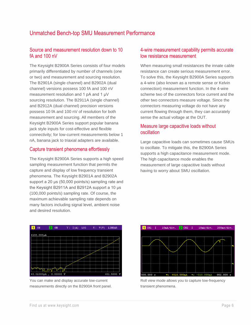
Source and measurement resolution down to 10 fA and 100 nV
The Keysight B2900A Series consists of four models
primarily differentiated by number of channels (one
or two) and measurement and sourcing resolution.
The B2901A (single channel) and B2902A (dual
channel) versions possess 100 fA and 100 nV
measurement resolution and 1 pA and 1 μV
sourcing resolution. The B2911A (single channel)
and B2912A (dual channel) precision versions
possess 10 fA and 100 nV of resolution for both
measurement and sourcing. All members of the
Keysight B2900A Series support popular banana
jack style inputs for cost-effective and flexible
connectivity; for low-current measurements below 1
nA, banana jack to triaxial adapters are available.
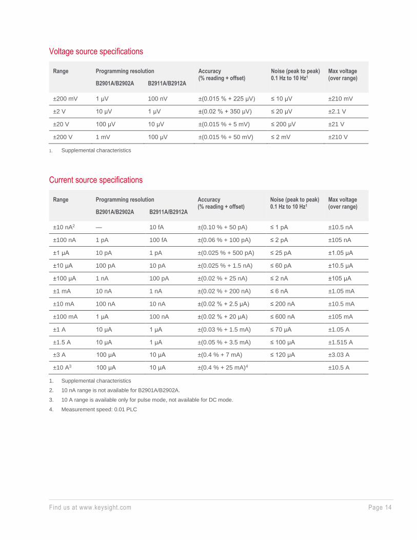
Capture transient phenomena effortlessly
The Keysight B2900A Series supports a high speed
sampling measurement function that permits the
capture and display of low frequency transient
phenomena. The Keysight B2901A and B2902A
support a 20 μs (50,000 points/s) sampling rate and
the Keysight B2911A and B2912A support a 10 μs
(100,000 points/s) sampling rate. Of course, the
maximum achievable sampling rate depends on
many factors including signal level, ambient noise
and desired resolution.
4-wire measurement capability permits accurate low resistance measurement
When measuring small resistances the innate cable
resistance can create serious measurement error.
To solve this, the Keysight B2900A Series supports
a 4-wire (also known as a remote sense or Kelvin
connection) measurement function. In the 4-wire
scheme two of the connectors force current and the
other two connectors measure voltage. Since the
connectors measuring voltage do not have any
current flowing through them, they can accurately
sense the actual voltage at the DUT.
Measure large capacitive loads without oscillation
Large capacitive loads can sometimes cause SMUs
to oscillate. To mitigate this, the B2900A Series
supports a high capacitance measurement mode.
The high capacitance mode enables the
measurement of large capacitive loads without
having to worry about SMU oscillation.
You can make and display accurate low-current
measurements directly on the B2900A front panel.
Roll view mode allows you to capture low-frequency
transient phenomena.

P
a
g
e
Find us at www.keysight.com Page 7
Ultra Fast Throughput Lowers Cost-of-test
Best-in-class measurement throughput
Although an excellent R&D tool, the Keysight
B2900A Series is also well-suited for production
test. It can achieve excellent accuracy and
repeatability at even short integration times. The
B2900A Series possesses the fastest measurement
speed of any SMU in its class.
Program memory and trace buffer features improve throughput
To reduce bus communication time, the B2900A
Series supports a program memory feature that
allows long strings of SCPI commands to be stored
on the instrument. These code sequences can be
executed by sending a single command across the
communication bus, greatly improving throughput for
frequently executed command strings. In addition,
the B2900A Series supports a trace buffer that can
store up to 100,000 data points. This allows the
results from multiple measurements to be
downloaded at once, thereby reducing data transfer
time and also improving overall throughput.
SCPI commands provide compatibility and versatility
Standard Commands for Programmable Instruments
(SCPI) are a popular and easy-to-understand
instrument control protocol. The Keysight B2900A
Series supports two SCPI command sets,
conventional and default, to provide both code
compatibility and flexibility. The conventional
command set has a large number of its commands
compatible with those of older SMUs (such as the
Keithley 2400) to minimize code conversion work.
The default command set supports advanced
Keysight B2900A Series features and they should
be used to fully utilize its performance and
capabilities.

P
a
g
e
Find us at www.keysight.com Page 8
Overview: Why Use an SMU?
Resource integration reduces measurement error
An SMU is an instrument that combines the capabilities of
a current source, a voltage source, a current meter and a
voltage meter (along with the capability to switch easily
between these various functions). Because the source
and measurement circuitry is closely integrated, the user
can achieve far better measurement performance with
less measurement error than would be possible by using
various independent instruments to make the same
measurement.
Feedback mechanism stabilizes voltage and current sourcing
Since SMUs have the ability to very accurately measure
their own current and voltage output, they have many
advantages over conventional power supplies. All SMUs
have internal feedback loops that provide instantaneous
feedback to the sourcing circuitry, which in-turn allows the
SMU output to remain accurate and stable even if the load
conditions change unexpectedly.
Limit (compliance) feature prevents device damage
SMUs also possess a voltage and current limit
(compliance) feature that allows the user to set limits and
to protect devices from damage caused by excessive
voltage or current. Although the SMU normally continues
to function when it reaches the user-specified limit value, it
can also be set to shutdown just like the over current
protection (OCP) and over voltage protection (OVP)
functions do on a power supply.
Accurate timing control of source and measurement resources
The integration of the source and measurement resources
in an SMU allows much tighter synchronization than would
be possible with separate instruments. Moreover, the
B2900A Series provides very flexible triggering options
that allow the measurements points to be defined
independently from the sourced current or voltage
waveform. On two channel units you can operate both
channels in synchronization or independently, and under
remote control you can trigger multiple units in unison
using a group trigger signal.
Simplified block diagram of the Keysight B2900A Series
Source block:
Precision voltage and current
source/sink with sweep, pulse and
AWG capabilities. Voltage/current
limit capability is also available.
Measurement block:
Precision voltage and current meter
with high speed digitizing capability.

P
a
g
e
Find us at www.keysight.com Page 9
Innovative GUI and 4.3" Color LCD Display Facilitate Fast Bench-top Test, Debug and Characterization
The B2900A’s front panel has many features that
make interactive use fast and friendly. These include
a 4.3” color LCD display, a USB2.0 memory I/O port,
an assist key, an alphanumeric keypad and a rotary
knob. The 4.3” color LCD display supports both
graphical and numerical view modes, and enables
test setup and check test results quickly. The
USB2.0 memory port supports easy data storing and
porting. The Innovative graphical user interfaces,
such as single view, dual view, graph view, roll view
and zoom, improves usability and productivity of
bench-top tests, debug and characterizations
dramatically.
Single view:
Single view provides basic and advanced settings and display
capabilities for the selected channel from the front panel of the
instrument. No additional controller or software is required.
Dual view:
Dual view provides the basic settings and display capabilities for
both channels 1 and 2. Up to 6. digits can be displayed in dual
view mode. This mode is available only for the B2902A/B2912A.
Graph view:
Graph View displays measurement results on XY graphs (such as
I-V and I-t/V-t curves) on up to 2 channels. This is useful for quick
evaluation of device characteristics, especially those obtained
from sweep measurements.
Roll view:
Roll view draws I-t or V-t curves similar to the curves drawn by a
strip chart recorder. Up to 1000 acquired data points can be
displayed and updated while the measurement is still in progress.
Roll view’s continuous measurement capability is especially
useful for monitoring low frequency phenomena. Roll view is
available only for the B2911A/B2912A.

P
a
g
e
Find us at www.keysight.com Page 10
Multiple Remote Control Choices Optimize Performance for Different Applications
The Keysight B2900A Series of SMUs offers multiple options for instrument remote control at little or no
cost. Four solutions are available: BenchVue, B2900A Graphical Web Interface, B2900A Quick IV
Measurement Software, and EasyEXPERT group+. These multiple software control options allow you to
choose the solution that best fits your particular application
BenchVue
BenchVue allows you to control the
B2900A SMUs as voltage/current
sources from a PC without the need
to do any programming. In addition,
because BenchVue supports a wide
variety of Keysight instruments
(oscilloscopes, meters, etc.) it is a
good choice when you need to
integrate together many different
types of instruments on a benchtop.
Graphical Web Interface
The Keysight B2900A has a built-in
LXI compliant web server that allows
any Java enabled web browser
(such as Internet Explorer) to control
it over the LAN. The graphical web
interface supports all of the basic
measurement functions such as
spot measurements, sweep
measurements and pulsed source
measurements. Since no special
software is required this feature is
convenient for making quick
measurements on the fly.

P
a
g
e
Find us at www.keysight.com Page 11
Quick I/V Measurement Software
Keysight B2900A Quick I/V
Measurement Software permits
easy measurement setup and
execution on a Windows-based PC.
It has a user-friendly GUI that can
be used with all of the B2900A’s
interfaces (LAN, USB and GPIB). It
can control up to four SMU channels
in any configuration of single and
dual channel units.
EasyEXPERTgroup+
Keysight EasyEXPERT group+
provides a powerful IV parametric
characterization solution for a wide
range of devices and materials. It
has an intuitive mouse and
keyboard driven graphical user
interface that simplifies common
characterization tasks such as test
setup and execution, data analysis,
data management/protection, etc.
Moreover, since it can support up to
eight SMU channels (four 2-channel
SMU units) EasyEXPERT group+
makes it easy to characterize multi-
terminal devices.

P
a
g
e
Find us at www.keysight.com Page 12
Available Accessories Facilitate Special Test Needs
Easy banana jack connectivity with various accessories
The Keysight B2900A uses convenient and low-cost
banana jack terminals, which support a variety of
cables, adaptors and accessories.
Banana to triaxial adaptor for low current measurement
Since banana jacks cannot support low current
measurement (i.e. measurements of 1 nA and
below), a banana jack to triaxial adapter is available
to permit the use of high-performance triaxial cables.
This makes it easy to connect to both triaxial-based
test fixtures and wafer probers. Of course, both 2-
wire and 4-wire triaxial adapters are available
Test fixtures for testing packaged devices
The Keysight N1295A Device/Component Test
Fixture provides a low-cost solution to quickly and
easily test packaged devices and components. It
has four triaxial inputs and supports voltage and
current measurements of up to 42 V and 1 A.
For more advanced packaged testing needs, the
Keysight 16442B test fixture provides more
capabilities. It offers support for higher pin count
devices, more flexible connectivity and an interlock
feature for safely applying voltages greater than 42
V. Keysight can supply adapters to use the 16442B
interlock with the B2900A’s digital output.
Banana jack to triaxial
adapters are available in
both 2-wire and 4-wire versions.
Using the available accessories and
furnished software you can create a
low-cost PC-based component testing solution.
The Keysight N1295A Device/Component
Test Fixture provides a low-cost solution
to quickly and easily test packaged
devices and components.

P
a
g
e
Find us at www.keysight.com Page 13
Specifications
Specification conditions
Temperature 23 °C ± 5 °C
Humidity 30% to 80% RH
After 60 minutes warm-up Ambient temperature change less than ± 3 °C after self-calibration execution
Calibration period 1 year
Measurement speed 1 PLC (power line cycle)
Maximum voltage and current
Max voltage Max current
DC or pulsed1 210 V 0.105 A
21 V 1.515 A2
6 V 3.03 A2
Pulsed only1 200 V 1.515 A
6 V 10.5 A
1. See “Maximum pulse width and duty cycle” in Pulse Source
Supplemental Characteristics for applicable maximum voltage and
current.
2. Max current limitation: For 21 V/1.515 A and 6 V/3.03 A ranges,
total max current is limited by the table below for using 2 channels.
Max current is not limited for using 1 channel only.
Maximum current limitation
Ch1 voltage Ch2 voltage Max total current limitation of Ch1 and Ch2
±(0 V < V ≤ 6 V) ±(0 V < V ≤ 6 V) Ch1 current + Ch2 current ≤ 4 A
±(0 V < V ≤ 6 V) ±(6 V < V ≤ 21 V) Ch1 current + Ch2 current x 1.6 ≤ 4 A
±(6 V < V ≤ 21 V) ±(0 V < V ≤ 6 V) Ch1 current + Ch2 current x 0.625 ≤ 2.5 A
±(6 V < V ≤ 21 V) ±(6 V < V ≤ 21 V) Ch1 current + Ch2 current ≤ 2.5 A
P
a
g
e
Find us at www.keysight.com Page 14
Voltage source specifications
Range Programming resolution Accuracy (% reading + offset)
Noise (peak to peak) 0.1 Hz to 10 Hz1
Max voltage (over range)
B2901A/B2902A B2911A/B2912A
±200 mV 1 μV 100 nV ±(0.015 % + 225 μV) ≤ 10 μV ±210 mV
±2 V 10 μV 1 μV ±(0.02 % + 350 μV) ≤ 20 μV ±2.1 V
±20 V 100 μV 10 μV ±(0.015 % + 5 mV) ≤ 200 μV ±21 V
±200 V 1 mV 100 μV ±(0.015 % + 50 mV) ≤ 2 mV ±210 V
1. Supplemental characteristics
Current source specifications
Range Programming resolution Accuracy (% reading + offset)
Noise (peak to peak) 0.1 Hz to 10 Hz1
Max voltage (over range)
B2901A/B2902A B2911A/B2912A
±10 nA2 — 10 fA ±(0.10 % + 50 pA) ≤ 1 pA ±10.5 nA
±100 nA 1 pA 100 fA ±(0.06 % + 100 pA) ≤ 2 pA ±105 nA
±1 μA 10 pA 1 pA ±(0.025 % + 500 pA) ≤ 25 pA ±1.05 μA
±10 μA 100 pA 10 pA ±(0.025 % + 1.5 nA) ≤ 60 pA ±10.5 μA
±100 μA 1 nA 100 pA ±(0.02 % + 25 nA) ≤ 2 nA ±105 μA
±1 mA 10 nA 1 nA ±(0.02 % + 200 nA) ≤ 6 nA ±1.05 mA
±10 mA 100 nA 10 nA ±(0.02 % + 2.5 μA) ≤ 200 nA ±10.5 mA
±100 mA 1 μA 100 nA ±(0.02 % + 20 μA) ≤ 600 nA ±105 mA
±1 A 10 μA 1 μA ±(0.03 % + 1.5 mA) ≤ 70 μA ±1.05 A
±1.5 A 10 μA 1 μA ±(0.05 % + 3.5 mA) ≤ 100 μA ±1.515 A
±3 A 100 μA 10 μA ±(0.4 % + 7 mA) ≤ 120 μA ±3.03 A
±10 A3 100 μA 10 μA ±(0.4 % + 25 mA)4 ±10.5 A
1. Supplemental characteristics
2. 10 nA range is not available for B2901A/B2902A.
3. 10 A range is available only for pulse mode, not available for DC mode.
4. Measurement speed: 0.01 PLC

P
a
g
e
Find us at www.keysight.com Page 15
Source supplemental characteristics
Temperature coefficient
(0 to 18°C and 28 to 50°C)
± (0.1 x accuracy) /°C
Max output power and source/sink limits 31.8 W
±6 V @ ±3.03 A, ±21 V @ ±1.515 A, ±210 V @ ±105 mA, four
quadrant source or sink operation
Current limit/compliance Accuracy is same as current source. Minimum value is 1 % of range,
or 1 nA in 10 nA range.
Voltage limit/compliance Accuracy is same as voltage source. Minimum value is 1 % of range,
or 20 mV in 200 mV range
Over range 101 % of source range for 1.5 A and 3 A ranges. 105 % of source
range other than 1.5 A and 3 A ranges. No over range for 200 V
range with current exceeding 105 mA pulse only condition.
Over temperature protection Output turns off then resets at over temperature sensed internally
Voltage output settling time
200 mV, 2 V ranges
20 V range
200 V range
Time required to reach within 0.1 % of final value at open load
condition. Step is 10 % to 90 % range
< 50 μs
< 110 μs
< 700 μs
Slew rate ≤ 0.36 V/μs, 20 V and 10 mA ranges, 10 MΩ load resistance
Current output settling time
10 nA, 100 nA ranges
1 μA range
10 μA, 100μA ranges
1 mA to 3 A ranges
Time required to reach within 0.1 % (0.3 % for 3 A range) of final
value at short condition. Step is 10 % to 90 % range
< 10 ms
< 500 μs
< 250 μs
< 80 μs
Noise 10 Hz to 20 MHz (V source) 3 mVrms, 20 V range
V source overshoot < ±(0.1 % + 10 mV). Step is 10 % to 90 % range, resistive load
I source overshoot < ±0.1 % (< ±0.3 % for 3 A range). Step is 10 % to 90 % range,
resistive load
Voltage source range change overshoot ≤ 250 mV. 100 kΩ load, 20 MHz bandwidth
Current source range change overshoot ≤ 250 mV/R load, 20 MHz bandwidth
P
a
g
e
Find us at www.keysight.com Page 16
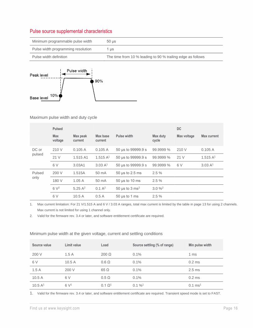
Pulse source supplemental characteristics
Minimum programmable pulse width 50 μs
Pulse width programming resolution 1 μs
Pulse width definition The time from 10 % leading to 90 % trailing edge as follows
Maximum pulse width and duty cycle
Pulsed DC
Max voltage
Max peak current
Max base current
Pulse width Max duty cycle
Max voltage Max current
DC or
pulsed
210 V 0.105 A 0.105 A 50 μs to 99999.9 s 99.9999 % 210 V 0.105 A
21 V 1.515 A1 1.515 A1 50 μs to 99999.9 s 99.9999 % 21 V 1.515 A1
6 V 3.03A1 3.03 A1 50 μs to 99999.9 s 99.9999 % 6 V 3.03 A1
Pulsed
only
200 V 1.515A 50 mA 50 μs to 2.5 ms 2.5 %
180 V 1.05 A 50 mA 50 μs to 10 ms 2.5 %
6 V2 5.25 A2 0.1 A2 50 μs to 3 ms2 3.0 %2
6 V 10.5 A 0.5 A 50 μs to 1 ms 2.5 %
1. Max current limitation: For 21 V/1.515 A and 6 V / 3.03 A ranges, total max current is limited by the table in page 13 for using 2 channels.
Max current is not limited for using 1 channel only.
2. Valid for the firmware rev. 3.4 or later, and software entitlement certificate are required.
Minimum pulse width at the given voltage, current and settling conditions
Source value Limit value Load Source settling (% of range) Min pulse width
200 V 1.5 A 200 Ω 0.1% 1 ms
6 V 10.5 A 0.6 Ω 0.1% 0.2 ms
1.5 A 200 V 65 Ω 0.1% 2.5 ms
10.5 A 6 V 0.5 Ω 0.1% 0.2 ms
10.5 A1 6 V1 0.1 Ω1 0.1 %1 0.1 ms1
1. Valid for the firmware rev. 3.4 or later, and software entitlement certificate are required. Transient speed mode is set to FAST.

P
a
g
e
Find us at www.keysight.com Page 17
Voltage measurement specifications
Range Measurement resolution Accuracy (% reading + offset)
B2901A/B2902A B2911A/B2912A
±200 mV 100 nV 100 nV ±(0.015 % + 225 μV)
±2 V 1 μV 1 μV ±(0.02 % + 350 μV)
±20 V 10 μV 10 μV ±(0.015 % + 5 mV)
±200 V 100 μV 100 μV ±(0.015 % + 50 mV)
1. Supplemental characteristics
Current measurement specifications
Range Measurement resolution Accuracy (% reading + offset)
B2901A/B2902A B2911A/B2912A
±10 nA1 — 10 fA ±(0.10 % + 50 pA)
±100 nA 100 fA 100 fA ±(0.06 % + 100 pA)
±1 μA 1 pA 1 pA ±(0.025 % + 500 pA)
±10 μA 10 pA 10 pA ±(0.025 % + 1.5 nA)
±100 μA 100 pA 100 pA ±(0.02 % + 25 nA)
±1 mA 1 nA 1 nA ±(0.02 % + 200 nA)
±10 mA 10 nA 10 nA ±(0.02 % + 2.5 μA)
±100 mA 100 nA 100 nA ±(0.02 % + 20 μA)
±1 A 1 μA 1 μA ±(0.03 % + 1.5 mA)
±1.5 A 1 μA 1 μA ±(0.05 % + 3.5 mA)
±3 A 10 μA 10 μA ±(0.4 % + 7 mA)
±10 A2 10 μA 10 μA ±(0.4 % + 25 mA)3
1. 10 nA range is not available for B2901A/B2902A.
2. 10 A range is available only for pulse mode, not available for DC mode.
3. Measurement speed: 0.01 PLC
P
a
g
e
Find us at www.keysight.com Page 18
Measurement supplemental characteristics
Temperature coefficient
(0 to 18°C and 28 to 50°C)
± (0.1 x accuracy) /°C
Over range 102 % of measurement range for 1.5 A and 3 A ranges
106 % of measurement range other than 1.5 A and 3 A ranges
Voltage measurement range change overshoot < 250 mV. 100 kΩ load, 20 MHz bandwidth
Current measurement range change overshoot < 250 mV/R load, 20 MHz bandwidth
Derating accuracy for measurement speed
less than 1 PLC
Add % of range using the following table for measurement with PLC < 1
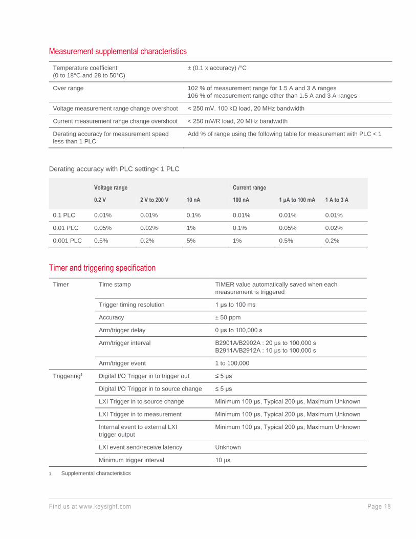
Derating accuracy with PLC setting< 1 PLC
Voltage range Current range
0.2 V 2 V to 200 V 10 nA 100 nA 1 μA to 100 mA 1 A to 3 A
0.1 PLC 0.01% 0.01% 0.1% 0.01% 0.01% 0.01%
0.01 PLC 0.05% 0.02% 1% 0.1% 0.05% 0.02%
0.001 PLC 0.5% 0.2% 5% 1% 0.5% 0.2%
Timer and triggering specification
Timer Time stamp TIMER value automatically saved when each
measurement is triggered
Trigger timing resolution 1 μs to 100 ms
Accuracy ± 50 ppm
Arm/trigger delay 0 μs to 100,000 s
Arm/trigger interval B2901A/B2902A : 20 μs to 100,000 s
B2911A/B2912A : 10 μs to 100,000 s
Arm/trigger event 1 to 100,000
Triggering1 Digital I/O Trigger in to trigger out ≤ 5 μs
Digital I/O Trigger in to source change ≤ 5 μs
LXI Trigger in to source change Minimum 100 μs, Typical 200 μs, Maximum Unknown
LXI Trigger in to measurement Minimum 100 μs, Typical 200 μs, Maximum Unknown
Internal event to external LXI
trigger output
Minimum 100 μs, Typical 200 μs, Maximum Unknown
LXI event send/receive latency Unknown
Minimum trigger interval 10 μs
1. Supplemental characteristics

P
a
g
e
Find us at www.keysight.com Page 19
Other supplemental characteristics
Output characteristics
Sensing Modes 2-wire or 4-wire (Remote-sensing) connections
Low terminal connection Chassis grounded or floating
Output connectors Banana jack. Triaxial connections are recommended for sourcing and measuring
less than 1 nA. A banana jack to triaxial adapter is available for low current
measurement.
Output location Channel 1 at front, and channel 2 at rear
Maximum load Normal mode: 0.01 μF
High Capacitance mode: 50 μF
DC loating voltage Max ±250 V DC between low force and chassis ground
Guard offset voltage (V source) < 4 mV
Remote sense operation range Max voltage between High Force and High Sense = 3 V
Max voltage between Low Force and Low Sense = 3 V
Common mode isolation > 1 GΩ, < 4500 pF
Maximum sense lead resistance: 1 kΩ for rated accuracy
Sense input impedance > 10 GΩ
High capacitance mode
The high capacitance mode permits the measurement of devices with capacitances greater than the normal mode
maximum load value of 0.01 μF. In high capacitance mode the maximum allowed value of the load capacitance is 50 μF.
Voltage output settling time
Time required to reach within 0.1 % of final value with 4.7 μF capacitive load on a
fixed range at specified current range and limit value
200 mV, 2 V ranges 600 μs, at 1 A limit
20 V range 1.5 ms, at 1 A limit
200 V range 20 ms, at 100 mA limit
Current measurement settling time
Time required to reach within 0.1 % of final value after voltage source is stabilized
on fixed range. Vout is 5 V unless noted.
1 μA range 230 ms
10 μA, 100 μA ranges 23 ms
1 mA, 10 mA ranges 0.23 ms
100 mA to 3 A ranges 100 μs
Mode
change delay
Delay into high
cap mode
1 μA range 230 ms
10 μA, 100 μA ranges 23 ms
1 mA to 3 A ranges 1 ms
Delay out of
high cap mode
All ranges 10 ms

P
a
g
e
Find us at www.keysight.com Page 20
Noise 10 Hz to 20 MHz (20 V range) 4.5 mVrms
Voltage source range change overshoot (20 V range or below) < 250 mV, 20 MHz bandwidth
High Capacitance
mode working conditions
V/I mode Voltage source mode only
Range Current measurement range is limited to fixed
range only. 10 nA and 100 nA ranges are not
available.
Current limit ≥ 1 μA
Resistance measurement
Resistance measurement can be performed under either auto or manual test conditions. Auto resistance measurement is
performed in current source and voltage measurement mode. The total auto resistance measurement error is shown in
the table below. The total error of a manual resistance measurement can be calculated using the voltage and current
accuracy information as shown below.
Source I mode, manual ohm
measurement (4-wire)
Total error = Vmeas/Isrc = R reading x (gain error % of V range + gain error % of
I range + offset error of I range/Isrc value %) + (offset error of V range/Isrc value)
Source V mode, manual ohm
measurement (4-wire)
Total error = Vsrc/Imeas = 1/ [1/R reading x (gain error % of I range + gain error
% of V range + offset error of V range/Vsrc value %) +
(offset error of I range/Vsrc value)]
Measurement speed 1 PLC
Applicable for temperature 23 °C ± 5 °C
Example of total error calculation I source value = 1 mA at 1 mA range
V measure range = 2 V range
Total error (% reading + offset) = (0.02 % + 0.02 % + 200 nA/1 mA) +
(350 μV/1 mA) = 0.06 % + 0.35 Ω
Typical performance of auto resistance measurement (4-wire), 2 V range
Range Resolution Test current Current range Total error (% reading + offset)
2 Ω 1 μΩ 1 A 1 A 0.2 % + 0.00035 Ω
20 Ω 10 μΩ 100 mA 100 mA 0.06 % + 0.0035 Ω
200 Ω 100 μΩ 10 mA 10 mA 0.065 % + 0.035 Ω
2 kΩ 1 mΩ 1 mA 1 mA 0.06 % + 0.35 Ω
20 kΩ 10 mΩ 100 μA 100 μA 0.065 % + 3.5 Ω
200 kΩ 100 mΩ 10 μA 10 μA 0.06 % + 35 Ω
2 MΩ 1 Ω 1 μA 1 μA 0.095 % + 350 Ω
20 MΩ 10 Ω 100 nA 100 nA 0.18 % + 3.5 kΩ
200 MΩ 100 Ω 10 nA 100 nA 1.08 % + 35 kΩ

P
a
g
e
Find us at www.keysight.com Page 21
System speeds
Maximum sweep operation reading rates (reading/second) for 50 Hz
Measure speed Measure to memory Measure to GPIB Source measure to memory
Source measure to GPIB
< 0.001 PLC 20000 12500 19500 12500
0.01 PLC 4500 3950 4500 3950
0.1 PLC 500 490 500 490
1 PLC 49 49 49 49
Operation reading rate varies by number of sweep steps. Number of sweep steps is specified.
Environmental specifications
Environment For use in indoor facilities
Operating 0 °C to +55 °C, 30 % to 80 % non-condensing
Storage -30 °C to 70 °C, 10 % to 90 % non-condensing
Altitude Operating: 0 m to 2000 m, Storage: 0 m to 4600 m
Power supply 90 V to 264 V, 47 Hz to 63 Hz, 250 VA maximum
EMC IEC61326-1/EN61326-1, AS/NZS CISPR 11, KC: RRA Notification amending Radio
Waves Act Article 58-2
Safety IEC61010-1/EN61010-1, CAN/CSA-C22.2 No. 61010-1-04, C/US
Certifications CE, cCSAus, C-Tick, KC
Warm-up 1 hour
Dimensions Case 88 mm (2U) x 213 mm (half width) x 450 mm
Working 180 mm x 260 mm x 480 mm (with handle & feet)
Weight Net 5.1 kg (B2901A, B2911A), 6.5 kg (B2902A, B2912A)
Shipping 7.6 kg (B2901A, B2911A), 9.0 kg (B2902A, B2912A)
Front panel operation
Front panel interface 4.3” TFT color display (480x272, with LED backlight) with keypads and rotary knob
View mode Single view, Dual view, Graph view and Roll view
Hardkeys Single Trigger and Auto Trigger control, 10-key, Rotary Knob and Cursors, Channel
on/off, View, Cancel/Local
Softkeys Function, System and Input Assist Keys
Indicators Channel (measurement) status, System status

P
a
g
e
Find us at www.keysight.com Page 22
Source/measurement capabilities
Sweep measurement
Number of steps 1 to 100,0001
Sweep mode Linear, logarithmic (log) or list
Sweep direction Single or double
Type DC, or pulse
Min programmable value to create list sweep waveform B2901A/B2902A: Min 20 μs with 1 μs resolution
B2911A/B2912A: Min 10 μs with 1 μs resolution
1. Valid for the models with S/N below or later, firmware rev. 3.1 or later ,and software entitlement certificate are
required. B2901A MY51140470 B2902A MY51140683 B2911A MY51140213 B2192A MY51140498 “1 to 2,500” for the models with other S/N.
Digitizing/sampling measurement
Min trigger interval (Max speed of measurement) B2901A/B2902A: 20 μs (50,000 points/s)
B2911A/B2912A: 10 μs (100,000 points/s)
Data buffers
Max buffer size 100,000 points / channel

P
a
g
e
Find us at www.keysight.com Page 23
Input/Output connectivity
GP-IB IEEE-488.2
Ethernet 100BASE-T / 10BASE-T
USB USB 2.0 host controller (front)
USB 2.0 device interface (rear)
Digital I/O Connector type 25-pin female D.
Input/output pins 14 open drain I/O bits
Absolute max input voltage 5.25 V
Absolute min input voltage - 0.25 V
Max logic L input voltage 0.8 V
Min logic H input voltage 2.0 V
Max source current 1 mA @ Vout = 0 V
Max sink current 50 mA @ Vout = 5 V
5 V power supply pin Limited to 500 mA, solid state fuse protected
Safety interlock pin: One active high pin and one active low pin. Activation of
both pin enables output voltage > 42 V
Maximum number of simultaneously
triggered units (using Digital I/O)1:
8
1. Supplemental characteristic
Program, software and drivers
Programming SCPI
Program memory 100 kB (2500 lines typical)
LXI compliance LXI Core 2011
Software available EasyEXPERT group+, Quick I/V Measurement Software, Graphical Web
Interface, BenchVue
Drivers available IVI-C, IVI-COM drivers, LabVIEW drivers

P
a
g
e
Find us at www.keysight.com Page 24
Software prerequisites
EasyEXPERTgroup+
Operating system Microsoft Windows Vista Business SP2 or later (32bit), Microsoft
Windows 7 Professional SP1 or later (32bit/64bit), Microsoft
Windows 8.1 Professional or later (32bit/64bit), Microsoft Windows
10 Pro or later (32bit/64bit)
Supporting language English (US)
.NET Framework Microsoft .NET, Framework 3.5 SP1
IO Libraries Keysight IO Libraries Suite 16.2, 16.3, 17.1 update 1 or later (for the
Online execution mode)
Memory 2 GB memory
Display XGA 1024 x 768 (SXGA 1280 x 1024 recommended)
HDD Installation: 1GB free disk space on the C drive, Test setup/result
data storage: Free disk space more than 30GB is recommended
Recommended GPIB I/F Keysight 82350B/C (PCI)1, 82351B(PCIe)1,
82357A (USB) 2, 3, 82357B (USB) 2, 3
National Instrument: GPIB-USB-HS (USB)2,1
Quick IV
Operating system Windows 7 (32 bit/64 bit), Windows 8 (32 bit/64 bit), Windows 8.1 (32
bit/64 bit), Windows 10 (32 bit/64 bit),
Supporting language English (US)
.NET Framework Microsoft .NET, Framework 4.5.2
IO Libraries 17.0 or later
Interfaces USB, GP-IB, LAN
BenchVue
Operating system Windows 10 32-bit and 64-bit (Professional, Enterprise, Education,
Home versions)
Windows 8 32-bit and 64-bit (Professional, Enterprise, Core)
Windows 7 SP1 and later 32-bit and 64-bit (Professional, Enterprise,
Ultimate, Home Basic, Home Premium)
HDD Processor: 1 GHz or faster (2 GHz or greater recommended)
RAM: 1GB (32-bit) or 2GB (64-bit) (3GB or greater recommended)
Display resolution 1024 x 768 minimum for single instrument view (higher resolutions
are recommended for multiple instrument view)
Interfaces USB, GPIB, LAN, RS-232
1. A PCI or PCIe card is highly recommended because of stability and speed. 2. USB GPIB interfaces might cause serial poll error intermittently due to the intrinsic communication scheme
differences. It is reported that using an even GPIB address sometimes significantly decreases the chance of the error. The NI GPIB-USB-HS is recommended for stability, and the Keysight 82357x is recommended for speed.
3. EasyEXPERT software prohibits to set the odd GPIB address to prevent th e issue above.

P
a
g
e
Find us at www.keysight.com Page 25
Learn more at: www.keysight.com
For more information on Keysight Technologies’ products, applications or services,
please contact your local Keysight office. The complete list is available at:
www.keysight.com/find/contactus
This information is subject to change without notice. © Keysight Technologies, 2019 - 2020, Published in USA, June 16, 2020, 5990-7009EN
Furnished Accessories
Power cable, USB cable, Quick Reference (English), CD-ROMs (including PDF manuals, Quick I/V
Measurement Software and drivers, EasyEXPERT group+ install media), Keysight I/O Library Suite
Ordering Information
Model number
B2901A Precision Source/Measure Unit, 1ch, 100 fA, 210 V, 3 A DC/10.5 A pulse
B2902A Precision Source/Measure Unit, 2ch, 100 fA, 210 V, 3 A DC/10.5 A pulse
B2911A Precision Source/Measure Unit, 1ch, 10 fA, 210 V, 3 A DC/10.5 A pulse
B2912A Precision Source/Measure Unit, 2ch, 10 fA, 210 V, 3 A DC/10.5 A pulse
Options
0B0 Download the Product Manual from the Keysight website
ABA User Guide English for B2900 Series
ABJ User Guide Japanese for B2900 Series
A6J ANSI Z540-1-1994 Calibration
UK6 Commercial Calibration Certificate with Test Data
Accessories
N1294A-001 Banana - Triax adapter for 2-wire (non Kelvin) connection
N1294A-002 Banana - Triax adapter for 4-wire (Kelvin) connection
N1294A-011 Interlock cable for 16442B (1.5 m)
N1294A-012 Interlock cable for 16442B (3.0 m)
N1294A-031 GPIO-BNC trigger adapter
N1294A-032 Digital I/O trigger cable for multiple unit control
16494A-001 Low leakage triax cable (1.5 m)
16494A-002 Low leakage triax cable (3.0 m)
16494A-005 Low leakage triax cable (4.0 m)
34190A Rack Mount Kit
Upgrade kit
B2901AU B2901A Software Upgrade Package, Extension Support and Subscription
B2902AU B2902A Software Upgrade Package, Extension Support and Subscription
B2911AU B2911A Software Upgrade Package, Extension Support and Subscription
B2912AU B2912A Software Upgrade Package, Extension Support and Subscription