b117 v c using synchrotron x-ray nano-ct to characterize...
TRANSCRIPT

Using Synchrotron X-Ray Nano-CT to Characterize SOFCElectrode Microstructures in Three-Dimensions at OperatingTemperature
P. R. Shearing,a,e,*,z R. S. Bradley,b J. Gelb,c S. N. Lee,d A. Atkinson,d,* P. J. Withers,b
and N. P. Brandona
aDepartment of Earth Science and Engineering and dDepartment of Materials, Imperial College, London SW7 2AZ,United KingdombHenry Moseley X-ray Imaging Facility, School of Materials, University of Manchester, Manchester, M1 7HS,United KingdomcXradia Inc., Pleasanton, California 94588, USA
In recent years, developments in tomography tools have provided unprecedented insight into the microstructure of electrodes forsolid oxide fuel cells, enabling researchers to establish direct links between electrode microstructure and electrochemical perform-ance. Here we present results of high resolution, synchrotron X-ray nano computed tomography experiments, which have enabledmicrostructural characterisation of a mixed ionic electronic conducting lanthanum strontium cobalt iron oxide (LSCF) cathodewith sub-50nm resolution at operating temperature. Using the uniquely non-destructive nano-CT platform, it is possible to charac-terise microstructural evolution processes associated with heating and operation in-situ.VC 2011 The Electrochemical Society. [DOI: 10.1149/1.3615824] All rights reserved.
Manuscript submitted June 1, 2011; revised manuscript received July 1, 2011. Published August 4, 2011.
Solid Oxide Fuel Cells (SOFC) are high temperature electrochem-ical energy conversion devices. Electrodes supporting the redox reac-tions are typically complex porous materials: the nature of this po-rous microstructure will affect the operation of the cell, contributingto resistances associated with electrochemical, diffusion, and ohmicprocesses. In spite of this, electrode microstructures have been, his-torically, poorly understood, with design and optimisation primarilydriven by empirical parametric testing.1 The lack of understanding ofSOFC microstructure has been compounded by microstructural evo-lution processes, which are known to occur during processing andoperation – physically altering the electrode microstructures, affect-ing cell performance and causing performance degradation.
The mixed ionic electronic conductor (MIEC) LSCF (Lantha-num Strontium Cobalt Iron Oxide – with typical composition La0.60
Sr0.40 Co0.20 Fe0.80 O3-d) has emerged as a promising cathode mate-rial for SOFCs, particularly suited to operation in the intermediatetemperature regime of 700–850 �C (IT-SOFCs).2
In recent years, advances in tomography procedures have pro-vided the SOFC research community with the tools to explore therelationship between electrode microstructure and performance withunprecedented detail. Numerous examples of 3D electrode charac-terisation utilising focused ion beam (FIB) and X-ray nano com-puted tomography (nano-CT) are extant in the literature (see Ref. 1and references therein). In particular Gostovic et al.3 have previ-ously reported studies of LSCF cathode materials using destructiveFIB tomography.
X-ray nano-CT provides a uniquely non-destructive solution, en-abling direct quantification of microstructural change in absence ofthe statistical differences inherent in material microstructures thatcan be problematic using destructive FIB tomography.
In order to explore, in real time, the microstructural evolutionprocesses that are known to occur in SOFCs, it is desirable to accesstemperatures and atmospheres associated with processing and oper-ation in-situ of the X-ray microscope stage. This is not possible inFIB-SEM systems because of the requirement for high vacuum.
Here we present, for the first time known to the authors, the de-velopment and implementation of a high temperature environmentin-situ of nano-CT X-ray microscope stage – providing a non-de-structive tomography platform with sub-50nm spatial resolution forcharacterisation of SOFC electrodes at operating temperatures.
Experimental
Sample preparation.— An LSCF ink was manufactured fromcommercially available powder and ink vehicle (Nextech Materials,OH, USA) utilising a conventional triple roll milling technique. Theresulting ink has been screen-printed in symmetrical cell configura-tion on to dense, iso-statically pressed CGO electrolytes (also Nex-tech Materials) and sintered at 900 �C for 2 h. The resulting electro-des were tested without DC bias using electrochemical impedancespectroscopy (Probostat Electrochemical Analyser with AutolabFRA). The resulting impedance spectra, normalised to 1 cm2 elec-trode area, with Ohmic contributions subtracted, are reproduced inFig. 1. The results show the typical Gerischer response of a mixedconducting cathode at low temperatures, with a second low fre-quency arc that is due to gas diffusion processes, which has a largerrelative contribution at higher temperatures.
A sample geometry optimised for fixed field of view (FOV)nano-CT was prepared using a FIB technique, described by theauthors elsewhere.4 The technique utilises the micro-machiningcapability of focused ion beams to create small (< 15 lm), robustsamples secured to a tungsten micro-needle using a Pt gas injectionsystem common to most FIB systems.5
Stage design and implementation.— Tomography experimentshave been conducted using the Xradia Transmission X-ray Micro-scope (TXM) at beam-line 32-ID at the Advanced Photon Source,Argonne National Lab, IL, USA. The system uses X-ray optics tofocus the beam before and after transmission, routinely achievingsub-50nm spatial resolution. This can be coupled with the variableX-ray energy to perform multiple energy scans and X-ray absorptionspectroscopy (XAS).6,7
A schematic of the stage geometry can be found in Lao et al.8
The precision rotation stage is situated between an order-sortingpin-hole (source side) and the focusing Fresnel zone plates (trans-mission side) - both components must be maintained close to ambi-ent temperature to avoid damage.
In order to access operating temperatures representative ofSOFCs, we have designed an infrared furnace for implementationin-situ of the TXM: a 250 W IR heater with elliptical reflector(Research Inc, MN, USA) provides a highly focused heat spot of ca.5 mm spread and a variable AC power input is used to modulate theheater power.
Implementation of the heat lamp in the TXM stage without con-tainment was found to rapidly increase the component temperaturesabove acceptable limits. Therefore a furnace chamber was designedwith a water-cooled jacket (see Fig. 2) to provide sufficient heattransfer for long-term operation of the heat lamp.
* Electrochemical Society Active Member.e Present address: Department Earth Science and Engineering, Imperial College,
SW7 2AZ and Department Chemical Engineering, University College London,London WC1E 6BT.
z E-mail: [email protected]; [email protected]
Electrochemical and Solid-State Letters, 14 (10) B117-B120 (2011)1099-0062/2011/14(10)/B117/4/$28.00 VC The Electrochemical Society
B117
Downloaded 04 Aug 2011 to 128.40.74.29. Redistribution subject to ECS license or copyright; see http://www.ecsdl.org/terms_use.jsp

The furnace chamber has X-ray transparent windows to preventattenuation of the beam, and an inlet gas stream can be used to studysamples in various gas environments. Using a 120 V power supplyat 2 A, a maximum temperature of 890 �C was recorded, with tem-perature stability of 65 �C over a period in excess of 12 h. Thermo-couple placement within 700 lm of the sample has been confirmedby projection microscopy and ensures accurate temperature mea-surement at the sample. Temperature measurements close to criticalcomponents did not exceed ambient temperature for this period.Whilst the stainless steel sample holder did record temperatures inexcess of 60 �C over the course of long-term operation, this slightelevation in temperature can be tolerated.
Imaging.— The LSCF cathode sample, prepared by a FIB lift-outtechnique, was inserted into the furnace at ambient temperature. 361
transmission images were collected at 0.5� increments over a 180�
rotation using 8.4 keV x-ray illumination and a pixel size corre-sponding to 15 nm.
After completing the first tomography sequence, the sample washeated in-situ to 695 �C at a rate of 50 �C/min. On reaching set pointtemperature, the sample was allowed to equilibrate at temperaturefor a period of 2 h – during this time, the sample movement (due tothermal expansion of the supporting needle) was monitored byX-ray transmission radiography. Once sample movements hadceased, another tomography sequence was acquired with the sameimaging parameters.
Detector reference images were captured before and after bothhigh and low temperature experiments to normalise tomographydata for any changing beam or detector conditions.
Figure 1. Nyquist plots of the polarisa-tion impedance of the cathodes. The solidsymbols show the frequency markers andare labelled with log10 (frequency/Hz).
Figure 2. (Color online) A water-cooledIR furnace is implemented in the TXM.The furnace and IR heat source are fixedindependently of the rotation stage, allow-ing full 360� sample rotation. (a) Sche-matic of the furnace implementation (b)photograph of stage with IR heater (c)without heater (Components: 1. CondenserLens, 2. Pinhole, 3. Water Cooled Cham-ber, 4. Rotation Stage, 5. Zone Plates withAl Foil Shielding, 6. IR Heat Lamp, – – –indicates X-ray path).
Electrochemical and Solid-State Letters, 14 (10) B117-B120 (2011)B118
Downloaded 04 Aug 2011 to 128.40.74.29. Redistribution subject to ECS license or copyright; see http://www.ecsdl.org/terms_use.jsp
The sample preparation technique demonstrated excellenttolerance to rapid thermal cycling and high temperature operation –additionally the X-ray alignment fiducial markers (spherical goldparticle supplied by Alfa Aesar) were stable in the heating regimeused, allowing for effective alignment of high- and low-temperaturedata sets.
The transmission data was aligned relative to a fiducial markerand reconstructed using the Xradia XMReconstructor software. Theresulting image sequence was segmented using a 3D watershed seg-mentation approach implemented in Avizo Fire (Visualization Sci-ences Group, Bordeaux, France). Identical parameters for imageanalysis were applied to the tomography data at 14 �C and 695 �C.
Results and Discussion
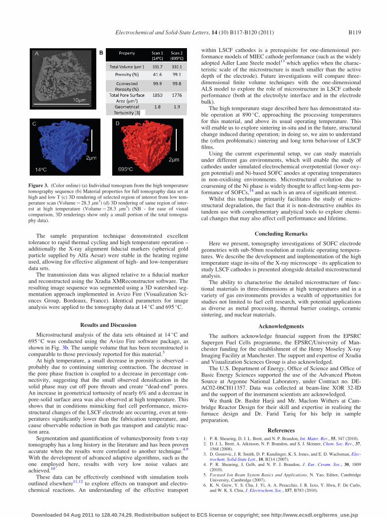
Microstructural analysis of the data sets obtained at 14 �C and695 �C was conducted using the Avizo Fire software package, asshown in Fig. 3b. The sample volume that has been reconstructed iscomparable to those previously reported for this material.3
At high temperature, a small decrease in porosity is observed –probably due to continuing sintering contraction. The decrease inthe pore phase fraction is coupled to a decrease in percentage con-nectivity, suggesting that the small observed densification in thesolid phase may cut off pore throats and create “dead-end” pores.An increase in geometrical tortuosity of nearly 6% and a decrease inpore-solid surface area was also observed at high temperature. Thisshows that in conditions mimicking fuel cell performance, micro-structural changes of the LSCF electrode are occurring, even at tem-peratures significantly lower than the fabrication temperature, andcause observable reduction in both gas transport and catalytic reac-tion area.
Segmentation and quantification of volumes/porosity from x-raytomography has a long history in the literature and has been provenaccurate when the results were correlated to another technique.4,9
With the development of advanced adaptive algorithms, such as theone employed here, results with very low noise values areachieved.10
These data can be effectively combined with simulation toolsoutlined elsewhere11,12 to explore effects on transport and electro-chemical reactions. An understanding of the effective transport
within LSCF cathodes is a prerequisite for one-dimensional per-formance models of MIEC cathode performance (such as the widelyadopted Adler Lane Steele model13 which applies when the charac-teristic scale of the microstructure is much smaller than the activedepth of the electrode). Future investigations will compare three-dimensional finite volume techniques with the one-dimensionalALS model to explore the role of microstructure in LSCF cathodeperformance (both at the electrolyte interface and in the electrodebulk).
The high temperature stage described here has demonstrated sta-ble operation at 890 �C, approaching the processing temperaturesfor this material, and above its usual operating temperature. Thiswill enable us to explore sintering in-situ and in the future, structuralchange induced during operation; in doing so, we aim to understandthe (often problematic) sintering and long term behaviour of LSCFfilms.
Using the current experimental setup, we can study materialsunder different gas environments, which will enable the study ofcathodes under simulated electrochemical overpotential (lower oxy-gen potential) and Ni-based SOFC anodes at operating temperaturesin non-oxidising environments. Microstructural evolution due tocoarsening of the Ni phase is widely thought to affect long-term per-formance of SOFCs,14 and as such is an area of significant interest.
Whilst this technique primarily facilitates the study of micro-structural degradation, the fact that it is non-destructive enables itstandem use with complementary analytical tools to explore chemi-cal changes that may also affect cell performance and lifetime.
Concluding Remarks
Here we present, tomography investigations of SOFC electrodegeometries with sub-50nm resolution at realistic operating tempera-tures. We describe the development and implementation of the hightemperature stage in-situ of the X-ray microscope - its application tostudy LSCF cathodes is presented alongside detailed microstructuralanalysis.
The ability to characterise the detailed microstructure of func-tional materials in three-dimensions at high temperatures and in avariety of gas environments provides a wealth of opportunities forstudies not limited to fuel cell research, with potential applicationsas diverse as metal processing, thermal barrier coatings, ceramicsintering, and nuclear materials.
Acknowledgments
The authors acknowledge financial support from the EPSRCSupergen Fuel Cells programme, the EPSRC/University of Man-chester funding for the establishment of the Henry Moseley X-rayImaging Facility at Manchester. The support and expertise of Xradiaand Visualization Sciences Group is also acknowledged.
The U.S. Department of Energy, Office of Science and Office ofBasic Energy Sciences supported the use of the Advanced PhotonSource at Argonne National Laboratory, under Contract no. DE-AC02-06CH11357. Data was collected at beam-line XOR 32-IDand the support of the instrument scientists are acknowledged.
We thank Dr. Bashir Harji and Mr. Maclom Withers at Cam-bridge Reactor Design for their skill and expertise in realising thefurnace design and Dr. Farid Tariq for his help in samplepreparation.
References
1. P. R. Shearing, D. J. L. Brett, and N. P. Brandon, Int. Mater. Rev., 55, 347 (2010).2. D. J. L. Brett, A. Atkinson, N. P. Brandon, and S. J. Skinner, Chem. Soc. Rev., 37,
1568 (2008).3. D. Gostovic, J. R. Smith, D. P. Kundinger, K. S. Jones, and E. D. Wachsman, Elec-
trochem. Solid-State Lett., 10, B214 (2007).4. P. R. Shearing, J. Gelb, and N. P. J. Brandon, J. Eur. Ceram. Soc., 30, 1809
(2010).5. Focused Ion Beam System Basics and Applications, N. Yao, Editor, Cambridge
University, Cambridge (2007).6. K. N. Grew, Y. S. Chu, J. Yi, A. A. Peracchio, J. R. Izzo, Y. Hwu, F. De Carlo,
and W. K. S. Chiu, J. Electrochem. Soc., 157, B783 (2010).
Figure 3. (Color online) (a) Individual tomogram from the high temperaturetomography sequence (b) Material properties for full tomography data set athigh and low T (c) 3D rendering of selected region of interest from low tem-perature scan (Volume¼ 28.3 lm3) (d) 3D rendering of same region of inter-est at high temperature (Volume¼ 28.3 lm3) (NB - for ease of visualcomparison, 3D renderings show only a small portion of the total tomogra-phy data).
Electrochemical and Solid-State Letters, 14 (10) B117-B120 (2011) B119
Downloaded 04 Aug 2011 to 128.40.74.29. Redistribution subject to ECS license or copyright; see http://www.ecsdl.org/terms_use.jsp

7. P. R. Shearing, J. Gelb, J. Yi, W. K. Lee, M. Drakopolous, and N. P. Brandon,Electrochem. Commun., 12, 1021 (2010).
8. S. H. Lao, W. K. S. Chiu, F. Garzon, H. Change, A. Tkachuk, M. Feser, and W.Yun, J. Phys.: Conf. Ser., 152, 012059 (2009).
9. J. R. Izzo, A. S. Joshi, K. N. Grew, W. K. S. Chiu, A. Tkachuk, S. H. Wang, andW. B. Yun, J. Electrochem. Soc., 155, B504 (2008).
10. P. Iassonov, T. Gebrenegus, and M. Tuller, Water Resour. Res., 45 (2009).
11. J. I. Golbert, C. S. Adjiman, and N. P. Brandon, Ind. Eng. Chem. Res., 47, 7693(2008).
12. P. R. Shearing, Q. Cai, J. I. Golbert, V. Yufit, C. S. Adjiman, and N. P. Brandon,J. Power Sources, 195, 4804 (2010).
13. S. B. Adler, J. A. Lane, and B. C. H. Steele, J. Electrochem. Soc., 143, 3554 (1996).14. A. Faes, A. Hessler-Wyser, D. Presvytes, C. G. Vayenas, and J. Van Herle, Fuel
Cells, 9, 841 (2009).
Electrochemical and Solid-State Letters, 14 (10) B117-B120 (2011)B120
Downloaded 04 Aug 2011 to 128.40.74.29. Redistribution subject to ECS license or copyright; see http://www.ecsdl.org/terms_use.jsp