b- columns of special moment framessite.iugaza.edu.ps/sshihada/files/2012/02/handout-8-2017.pdf181...
TRANSCRIPT

181
B- Columns of Special Moment Frames
ACI 18.7 applies to columns of special moment frames that form part of the
seismic- force-resisting system and proportioned primarily to resist flexure, shear
and axial forces. This section applies to columns of special moment frames
regardless of the magnitude of axial force. Before 2014, the Code permitted
columns with low levels of axial stress to be detailed as beams
1- Dimensional Limits:
ACI 18.7.2 requires that the following conditions are to be satisfied:
The shortest cross-sectional dimension, measured on a straight line passing
through the geometric centroid, shall not be less than 30 cm.
The ratio of shortest cross-sectional dimension to the perpendicular
dimension shall not be less than 0.40.
2- Minimum Flexural Strength of Columns:
Based on ACI 18.7.3.2, The flexural strengths of the columns shall satisfy
the following equation:
nbnc
MM 2.1
where
ncM = sum of nominal flexural strengths of columns framing into the joint,
evaluated at the faces of the joint. Column flexural strength shall be calculated
for the factored axial force, consistent with the direction of the lateral forces
considered, resulting in the lowest flexural strength.
nbM = sum of nominal flexural strengths of the beams framing into the joint,
evaluated at the faces of the joint. Flexural strengths shall be summed such that
the column moments oppose the beam moments.
The intent of the above equation is to reduce the likelihood of inelastic action.
If columns are not stronger than beams framing into a joint, flexural yielding
can occur at both ends of all columns in a given story, resulting in a column
failure mechanism that can lead to collapse.
For columns not satisfying the previous equation, the lateral strength and
stiffness of these columns shall be ignored when calculating strength and
stiffness of the structure. These columns shall conform to ACI 18.14
(frame members not proportioned to resist forces induced by earthquake
motions).

182
Strong column-weak beam requirements for special moment frames
3- Longitudinal Reinforcement:
ACI 18.7.4 requires that the following conditions are to be satisfied:
Area of longitudinal reinforcement, stA shall be at least gA01.0 and shall
not exceed gA06.0 . The lower limit of the area of longitudinal
reinforcement is to control time-dependent deformations and to have the
yield moment exceed the cracking moment. The upper limit of the area
reflects concern for reinforcement congestion.
In columns with circular hoops, there shall be at least six longitudinal
bars.
Lap splices are permitted only within the center half of the member
length, and shall be designed as tension lap splices and enclosed within
transverse reinforcement conforming to ACI 18.7.5.2 and 18.7.5.3.

183
Typical lap splice details of columns in special moment frames
4- Transverse Reinforcement:
Transverse reinforcement required in ACI 18.7.5.2 through 18.7.5.4 shall be
provided over a length l from each joint face and on both sides of any
section where flexural yielding is likely to occur as a result of lateral
displacements beyond the elastic range of behavior. The length l shall be at
least the largest of (a) through (c):
(a) The depth of the column at the joint face or at the section where flexural
yielding is likely to occur;
(b) 1/6 of the clear span of the member; and
(c) 45 cm.
Research results indicate that the length should be increased by 50 percent or
more in locations, such as the base of a building, where axial loads and
flexural demands may be especially high.
ACI 18.7.5.2 requires that the transverse reinforcement shall satisfy the
following:

184
(a) Transverse reinforcement shall comprise either single or overlapping
spirals, circular hoops, or rectilinear hoops, with or without crossties.
(b) Bends of rectilinear hoops and crossties shall engage peripheral
longitudinal reinforcing bars.
(c) Crossties of the same or smaller bar size as the hoops shall be permitted,
subject to limitations of 25.7.2.2 (column tie diameter). Consecutive
crossties shall be alternated end for end along the longitudinal
reinforcement and around the perimeter of the cross section.
(d) Where rectilinear hoops or crossties are used, they shall provide lateral
support to longitudinal reinforcement in accordance with 25.7.2.2 and
25.7.2.3 (column tie arrangement).
e) Reinforcement shall be arranged such that the spacing xh of longitudinal
bars laterally supported by the corner of a cross tie or hoop leg shall not
exceed 35 cm around the perimeter of the column.
f) Where cgu fAP 3.0 or 2/700 cmKgfc in columns with rectilinear
hoops, every longitudinal bar around the perimeter of the column core
shall have lateral support provided by the corner of a hoop or by a seismic
hook, and the value of xh shall not exceed 20 cm. uP shall be the largest
value in compression consistent with factored load combinations
including E.
Example of transverse reinforcement in columns
Spacing of transverse reinforcement along the length l of the member shall
not exceed the smallest of (a), (b) and (c):

185
(a) one-fourth of the minimum member dimension;
(b) six times the diameter of the smallest longitudinal bar
(c)
3
3510 xh
s , where s shall not exceed 15 cm and need not be
taken less than 10 cm.
Amount of transverse reinforcement shall be in accordance with Table
18.7.5.4. The concrete strength factor fk and confinement effectiveness
factor nk are calculated as shown below:
0.160.01750
cf
fk
2
l
ln
n
nk
where ln is the number of longitudinal bars around the perimeter of the
column core with rectilinear hoops that are laterally supported by the corner
of hoops or by seismic hooks.
where
ytf = yield stress of the transverse reinforcement
gA = gross cross-sectional area of concrete section
chA = cross-sectional area of a column measured to the outside edges of
transverse reinforcement.

186
s center-to-center spacing of transverse reinforcement measured along the
longitudinal axis of the column.
Expressions (a), (b), and (c) in Table 18.7.5.4 are to be satisfied in both
cross-sectional directions of the rectangular core. For each direction, cb is the
core dimension perpendicular to the tie legs that constitute shA , as shown in
Fig. R18.7.5.2.
Beyond the length l , the column shall contain spiral or hoop reinforcement
satisfying 25.7.2 through 25.7.4 (column ties/spirals) with center-to-center
spacing, s , not exceeding the lesser of six times the diameter of the smallest
longitudinal column bars and 15 cm, unless a greater amount of transverse
reinforcement is required by 18.7.5.2, 18.7.5.3, or 18.7.6 (shear strength) .
Columns supporting reactions from discontinued stiff members, such as
walls, shall satisfy (a) and (b):
(a) Transverse reinforcement required by 18.7.5.2 through 18.7.5.4 shall be
provided over the full height at all levels beneath the discontinuity if the
factored axial compressive force in these members, related to earthquake
effect, exceeds gc Af '1.0 . Where design forces have been magnified to
account for the over-strength of the vertical elements of the seismic-force-
resisting system, the limit of gc Af '1.0 shall be increased to gc Af '25.0 .
(b) Transverse reinforcement shall extend into the discontinued member at
least dl of the largest longitudinal column bar, where dl is determined in
accordance with ACI 18.8.5 (development length of bars in tension). Where
the lower end of the column terminates on a wall, the required transverse
reinforcement shall extend into the wall at least dl of the largest longitudinal
column bar at the point of termination. Where the column terminates on a
footing or mat, the required transverse reinforcement shall extend at least 30
cm into the footing or mat.

187
Confinement requirements at column ends
(a) Spiral hoop reinforcement

188
Confinement requirements at column ends
(b) Rectangular hoop reinforcement
Columns supporting discontinued stiff members

189
5- Shear Strength Requirements:
The design shear force, eV , is to be determined from consideration of
maximum forces that can be generated at the faces of the joint at each end of
the column. These joint forces shall be determined using the maximum
probable moment strengths, prM , of the column associated with the range of
factored axial loads, uP , acting on the column. The column shears need not
exceed those calculated from joint strengths based on the probable moment
strength prM of the beams framing into the joint. In no case shall eV be less
than the factored shear determined by analysis of the structure.
Transverse reinforcement over the length l given in 18.7.5.1, shall be
designed to resist shear assuming 0cV when both (a) and (b) occur:
i. The earthquake-induced shear force represents ½ or more of the maximum
required shear strength within l ;
ii. The factored axial compressive force, uP , including earthquake effects is
less than cg fA '05.0 .
Loading cases for design of shear reinforcement in columns of special
moment frames

190
Example (9):
For the column shown in the figure, check the requirements of ACI 18.7 in relation
to columns which are part of special moment frames.
Note that factored loads are: tons337Pu and tons4.84Mu .
Use 2c cm/Kg300'f and 2
y cm/Kg4200f .
Solution:
A- 18.7.2 "Dimensional limits":
Based on ACI 18.7.2.1, the shortest cross-sectional dimension, measured on
a straight line passing through the geometric centroid shall not be less than
30 cm. This requirement is satisfied since the shortest cross-sectional
dimension = 45 cm.

191
The ratio of the shortest cross-sectional dimension to the perpendicular
dimension shall not be less than 0.40.
Ratio = 40.064.070
45 (O.K)
B- ACI 18.7.3 "Minimum Flexural Strengths of Columns":
Based on ACI 18.7.3.2, the flexural strengths of the columns shall satisfy
the following equation:
nbnc MM 2.1
Considering the columns on both sides of the joint are of equal flexural
strengths, the flexural strength of each of the columns is determined using
nominal strength interaction diagrams.
01558.0g
, ksif c 4' ,
821.070
5.2124270
, tons337Pu
55.0457030065.0
1000337/
gc
nn
Af
PK
Using nominal load-moment strength interaction diagram, L4-
60.80, 165.0' hAf
M
gc
n and thereby mtMn .15.109
From example (8),
m.t35.41veMveM nlnr and mtveMveMnlnr
.82.59
mtMnc .30.21815.10915.109 , mtMnb .17.10182.5935.41
2.116.217.101
3.218
nb
nc
M
M (O.K)

192
C- ACI 18.7.4 "Longitudinal Reinforcement":
Based on ACI 18.7.4.1, the reinforcement ratio g shall not be less than 0.01
and shall not exceed 0.06.
01558.0
7045
087.49g (O.K)
Based on ACI 18.7.4.3, lap splices are only permitted within the center half
of the member length and shall be designed as tension lap splices enclosed
within transverse reinforcement in accordance with ACI 18.7.5.2 and
18.7.5.3.
Length of lap splice of longitudinal bars (in tension):
For Class "B" lap splice, dsp l3.1l
b
c
b
trb
sety
d d
fd
Kc
fl
'5.3
1t , 1e , 1s , and 1
bc = 4.0 + 1.0 + 1.25 = 6.25 cm
or
bc = [(45 – 4 (2) – 2 (1) – 2.5]/ (8) = 4.0625 cm
i.e., bc is taken as 4.0625 cm
Ignoring the effect of transverse reinforcement, 0K tr
5.2625.15.2
00625.4
b
trb
d
Kc
59.1065.2300625.15.3
0.14200
dl
Required splice length cmlsp 57.13859.1063.1 , taken as 140 cm.
Based on ACI 18.7.5.3, transverse reinforcement shall be spaced at a distance
not exceeding (a) one-quarter of the minimum column dimension, (b) six
times the diameter of the smallest longitudinal bar, and (c)
3
3510 xh
s ,
where S is maximum longitudinal spacing of transverse reinforcement, shall
not exceed 15 cm and need not be taken less than 10 cm. In the same
193
expression xh is maximum horizontal spacing of hoop or crosstie legs on all
faces of the column.
Thus, mmaximum vertical spacing of transverse reinforcement is not to
exceed the smallest of :
i. 45/4 = 11.25 cm
ii. 6 (2.5) = 15 cm
iii.
3
3510 xh
s = 10 cm
cm5.30
2
14270h x
. Thus maximum spacing is limited to 10 cm
(based on the minimum of i, ii and iii).
Based on ACI 18.7.5.2 (e), the spacing xh of bars laterally supported by the
corner of a crosstie or hoop leg shall not exceed 35 cm around the perimeter
of the column.
Two cross ties are added to the existing mm10 hoops to satisfy this
requirement (maximum spacing of 35 cm).
Based on ACI 18.7.5.2 (f), column load =337 tons and tonstonsfA cg 33750.2831000/30070453.03.0
Therefore, xh shall not exceed 20 cm.
D- 18.7.5 "Transverse Reinforcement":
Based on ACI 18.7.5.4 (b), the total cross-sectional area of rectangular hoop
reinforcement shall be based on Table 18.7.5.4
For shear in the direction of shorter side of the column:
0.177.060.01750
300fk , taken as 1.0
25.18
10nk
2
2 96.416237
7045
4200
30062103.0cmAsh
2
'2 98.34200
300621009.0cmAsh
2
2 43.5621062374200
33700025.10.120.0 cmAsh
i.e., 2
2 43.5 cmAsh
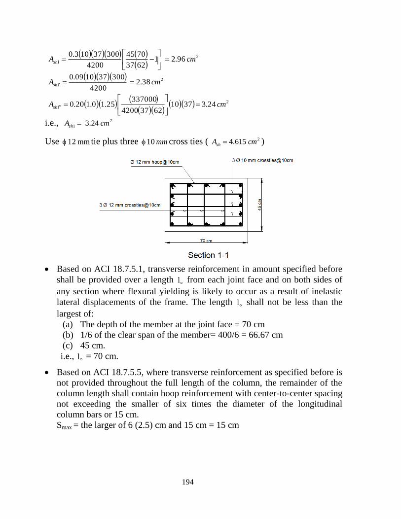
Use mm12 tie plus three mm12 cross ties ( 265.5 cmAsh )
For shear in the direction of longer side of the column:
194
2
1 96.216237
7045
4200
30037103.0cmAsh
2
1 38.24200
300371009.0cmAsh
2
1 24.3371062374200
33700025.10.120.0 cmAsh
i.e., 2
1 24.3 cmAsh
Use mm12 tie plus three mm10 cross ties ( 2615.4 cmAsh )
Based on ACI 18.7.5.1, transverse reinforcement in amount specified before
shall be provided over a length l from each joint face and on both sides of
any section where flexural yielding is likely to occur as a result of inelastic
lateral displacements of the frame. The length l shall not be less than the
largest of:
(a) The depth of the member at the joint face = 70 cm
(b) 1/6 of the clear span of the member= 400/6 = 66.67 cm
(c) 45 cm.
i.e., l = 70 cm.
Based on ACI 18.7.5.5, where transverse reinforcement as specified before is
not provided throughout the full length of the column, the remainder of the
column length shall contain hoop reinforcement with center-to-center spacing
not exceeding the smaller of six times the diameter of the longitudinal
column bars or 15 cm.
Smax = the larger of 6 (2.5) cm and 15 cm = 15 cm

195
E- ACI 18.7.6 "Shear Strength Reinforcement":
The design shear force eV is to be determined from consideration of
maximum forces that can be generated at the faces of the joint at each end of
the column. These joint forces shall be determined using the maximum
probable moment strengths prM of the column associated with the range of
factored axial loads acting on the column. The column shears need not
exceed those determined from joint strengths based on the probable moment
strength prM of the beams framing into the joint. In no case shall eV be less
than the factored shear determined by analysis of the structure.
tonsVe 865.30
4
77.5069.7277.5069.722/1
(see Example 8 for prM
values)
cm55.6325.12.1470d
tons25.261000/55.634530053.0Vc (neglecting effect of axial force)
cns VVV and cu
s VV
V

196
tons90.1425.2675.0
865.30Vs
S
dfAV
yvs and
0558.055.634200
10009.14
df
V
S
A
y
sv
0558.00375.0
4200
455.3
S
A
min
v
(O.K)
For cmsS 15 , 2837.0 cmAv (satisfied at sections 1-1, 2-2 and 3-3).

197
B- Columns of Intermediate Moment Frames
Requirements of ACI 18.4.3 are applicable for columns of intermediate moment
frame columns forming part of the seismic-force resisting system.
1- Transverse Reinforcement:
At both ends of the column, hoops shall be provided at spacing s over a
length l measured from the joint face.
The length l shall not be less than the largest of:
(a) 1/6 of the clear span of the column
(b) Maximum cross-sectional dimension of the column
(c) 45 cm.
The spacing s shall not exceed the smallest of:
(a) 8 times the diameter of the smallest longitudinal column bar
(b) 24 diameter of the hoop bar
(c) One-half of the smallest cross-sectional dimension of the column
(d) 30 cm.
The first hoop shall be located not more than 2/s from the joint face.
Outside the length l , spacing of the transverse reinforcement shall conform
to ACI 10.7.6.5.2 (maximum spacing of shear reinforcement).
Columns supporting reactions from discontinuous stiff members, such as
walls, shall be provided with transverse reinforcement at the spacing s in
accordance with 18.4.3.3 over the full height beneath the level at which the
discontinuity occurs if the portion of factored axial compressive force in
these members related to earthquake effects exceeds gc Af '1.0 . If design
forces have been magnified to account for the overstrength of the vertical
elements of the seismic-force-resisting system, the limit of gc Af '1.0 shall be
increased to gc Af '25.0 . Transverse reinforcement shall extend above and
below the column in accordance with 18.7.5.6(b).
Columns shall be spirally reinforced in accordance with Chapter 10 or shall
be in accordance with 18.4.3.3 through 18.4.3.5, discussed in 1. Provision
18.4.3.6 shall apply to all columns supporting discontinuous stiff members

198
2- Shear Strength Requirements:
Design shear strength of columns nV resisting earthquake effect shall be at
least the lesser of (a) and (b):
(a) The shear associated with development of nominal moment
strengths of the column at each restrained end of the unsupported
length due to reverse curvature bending. Column flexural strength
shall be calculated for the factored axial force, consistent with the
direction of the lateral force considered, resulting in the highest
flexural strength.
(b) The maximum shear obtained from factored load combinations that
include E, with E substituted for E.

199

200
B- Columns of Ordinary Moment Frames
Requirements of ACI 18.3.3 are applicable to columns of ordinary moment frames
forming part of the seismic-force resisting system and classified as SDC "B".
Shear Strength Reinforcement:
Columns having unsupported length 15clu shall have at least the lesser of (a) and
(b):
(a) The shear associated with development of nominal moment strengths of the
column at each restrained end of the unsupported length due to reverse
curvature bending. Column flexural strength shall be calculated for the
factored axial force, consistent with the direction of the lateral forces
considered, resulting in the highest flexural strength.
(b) The maximum shear obtained from design load combinations that include E ,
with E substituted for E .