azw84-67902 2/3 hole punch kit cz999-67902 2/4 hole punch kit
TRANSCRIPT

AZW84-67902 2/3 Hole Punch KitCZ999-67902 2/4 Hole Punch Kit
1
1 2
Turn the product off, and then disconnect the finishing accessory from the product.
On the finishing accessory, remove four screws from the latch lower covers.NOTE: The booklet maker with hole punch accessory is shown in these photos, however the procedure is correct for all of the finishing accessories.
CAUTION: Exposed sheet metal can have sharp edges. Be careful when working around exposed sheet metal.
Lea esto primero
www.hp.com/support/colorljM855www.hp.com/support/colorljflowMFPM880
2
7
5
8
6
43
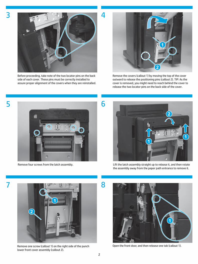
Remove the covers (callout 1) by moving the top of the cover outward to release the positioning pins (callout 2). TIP: As the cover is removed, you might need to reach behind the cover to release the two locator pins on the back side of the cover.
Before proceeding, take note of the two locator pins on the back side of each cover. These pins must be correctly installed to assure proper alignment of the covers when they are reinstalled.
Remove four screws from the latch assembly. Lift the latch assembly straight up to release it, and then rotate the assembly away from the paper path entrance to remove it.
Remove one screw (callout 1) on the right side of the punch lower front cover assembly (callout 2).
Open the front door, and then release one tab (callout 1).
3
11
13
9
12
14
10
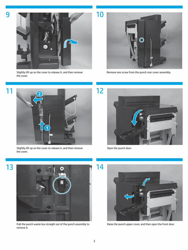
Slightly lift up on the cover to release it, and then remove the cover.
Remove one screw from the punch rear cover assembly.
Slightly lift up on the cover to release it, and then remove the cover.
Open the punch door.
Pull the punch waste box straight out of the punch assembly to remove it.
Raise the punch upper cover, and then open the front door.
4
17 18
20
15
19
16
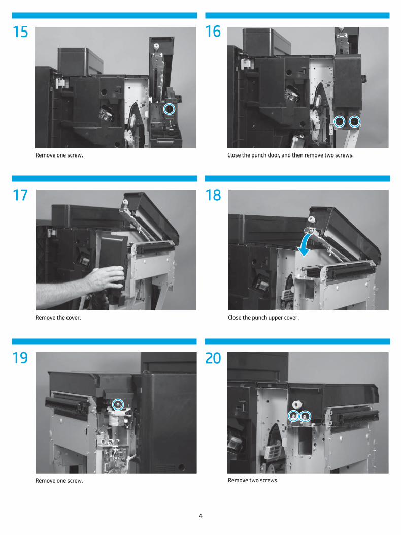
Remove one screw. Close the punch door, and then remove two screws.
Remove the cover. Close the punch upper cover.
Remove one screw. Remove two screws.

5
23
25
24
26
2221
Remove the cover.
Disconnect three connectors (callout 1) on the controller PCA, and then release the wire harnesses from one retainer (callout 2).
Remove two screws.TIP: These screws fasten the rear sheet-metal support bracket to the punch assembly. Use the hole provided in the chassis next to the punch controller PCA to gain access to these screws.
Slightly lift up on the punch hole assembly (callout 1), and then disengage the sheet-metal support bracket (callout 2).NOTE: The punch hole assembly is still fastened to the accessory chassis, but you should be able to disengage the support bracket.
Remove two screws.
Slightly raise the front edge of the cover, and then slide the cover towards the rear of the accessory to release it.

6
29
27
30
28
31
Slightly lift up on the punch hole assembly (callout 1), and then disengage the sheet-metal support bracket (callout 2).NOTE: The punch hole assembly is still fastened to the accessory chassis, but you should be able to disengage the support bracket.
Remove one screw.
Remove one screw. Lift the assembly up to release it, and then remove the assembly.
Responsibly dispose of the failed assembly. Unpack the replacement assembly. If present, remove all packing materials.Installation is the reverse of removal.NOTE: See the special installation instructions section on the following pages after installing the replacement assembly.

Special installation instructions
7
3 4
1 2
Follow these steps to adjust for skewed hole alignment. This adjustment procedure only moves the front portion of the punch to move the front hole in alignment with the rear hole.
a. Open the punch door and upper cover.b. Loosen the adjustment screw (callout 1), and then move
the punch plate to the right or to the left as necessary to bring the front punched hole in alignment with the rear hole.
c. Tighten the adjustment screw. IMPORTANT: Fully tighten the adjustment screw after making each adjustment and before closing the upper cover to make sure that the punch position does not move.
d. Close the punch door and upper cover.e. Print five test pages and continue adjusting until all the
holes are aligned on the page.f. After adjustment is completed, print 25 test pages to
assure alignment remains constant. NOTE: If some pages have skewed holes while others do not, the problem is a skew in the paper and not the punch.
Correct punch hole alignment. NOTE: The 12 mm (.47 in) distance from the trailing edge of the paper is calculated in firmware and cannot be adjusted.
Reconnect the finishing accessory to the product. Turn the power on. After the product has initialized, send a hole punch print job to the accessory. Check the printed page and verify that the holes are punched in the correct page location.
Punch adjustment is required when the punch holes are misaligned. If the holes are not aligned, identify in which direction the punched hole adjustment is required. This figure shows the punched hole misaligned to the left.

8
7 8
14
5
2 3
1
ON
2 3 4
5 6
9
Locate the switches and LEDs on the punch controller PCA.
• SW601 (callout 1)• LED602 (callout 2)• LED601 (callout 3)• SW602 (callout 4)• SW603 (callout 5)
NOTE: SW601 has four electronic switches that can be configure in the ON or OFF position. The punch controller PCA is marked ON and OFF to show the current switch position.
Set SW601 to the settings above.
Set the punch hole assembly type.Two types of punch hole assemblies are available: the 2/3 punch hole assembly (part number A2W94-67901), or the 2/4 punch hole assembly (part number CZ999-67902). Refer to the part number on the replacement part to determine the type of assembly you are installing. Follow the steps below to set the punch hole assembly type.
Turn the product off.
Turn the product power on.

9
12
1
ON
2 3 4
10 11
Return all of the switches on SW601 to the OFF position.
Follow these steps to set the punch hole assembly type.
a. Press SW602 and observe the blinking pattern of LED601 and LED602. The table above explains the different blinking patterns.
b. Continue pressing SW602 until the blinking pattern matches the type of punch hole assembly you are installing. For example, if you are installing a 2/4 punch hole assembly (part number CZ999-67902), press SW602 until both LED601 and LED602 blink three times.
c. Once the LEDs are blinking in the correct pattern, press SW603 to store the punch hole assembly type value in memory.
d. Wait until LED601 is not lit and LED602 is blinking steadily to indicate the type setting is complete.
e. Press either SW602 or SW603.f. Wait until only LED602 is blinking.
LED601 LED602 LED blinking pattern explanation
Blinking one time Not applicable
Blinking two times 2/3 punch hole assembly selected
Blinking three times 2/4 punch hole assembly selected
Blinking four times Waiting for type setting completion
Not lit Blinking steadily
Type setting completed Turn the product off.

10
13 14
15
14
5
2 3
16
1
ON
2 3 4
17
Set the sensor adjustment values.Follow the steps below to adjust the sensors on the punch controller PCA.
Make sure that the product power is off.
Locate the switches and LEDs on the punch controller PCA.
• SW601 (callout 1)• LED602 (callout 2)• LED601 (callout 3)• SW602 (callout 4)• SW603 (callout 5)
NOTE: SW601 has four electronic switches that can be configure in the ON or OFF position. The punch controller PCA is marked ON and OFF to show the current switch position.
Set SW601 to the settings above.
Turn the product power on.

11
20
1
ON
2 3 4
18 19
21
Return all of the switches on SW601 to the OFF position.
Follow these steps to adjust the sensors on the punch controller PCA.
a. Press SW602 and observe the blinking pattern of LED601 and LED602. The table above explains the different blinking patterns.
b. Wait until LED601 is not lit and LED602 is blinking steadily to indicate the sensor adjustment is complete.
c. Press either SW602 or SW603.d. Wait until only LED602 is blinking.
LED601 LED602 LED blinking pattern explanation
Solidly lit Blinking steadily
Adjusting sensors
Blinking alternately Waiting for adjustment completion
Not lit Blinking steadily
Sensor adjustment completed
Turn the product off.
Turn the product power on.
12
A2W84-91001A2W84-91001
© Copyright 2015 HP Development Company, L.P.