aztek body panel complete manual
TRANSCRIPT

2001 Pontiac Aztek 1-1
Radiator SupportReplacement(Upper)Removal Procedure1. Remove all related panels and
components including front fasciasupports, right and left (1).
2. Restore as much of the damage aspossible to factory specifications.
3. Note the location and remove thefollowing as necessary:
• Sealers
• Sound deadeners
• Anti-corrosion materials
IMPORTANT: Do not damage anyinner panels or reinforcements.
4. Locate and drill out all factorywelds. Note the number andlocation of welds for installation ofthe Radiator Support Assembly.
5. Remove the damaged RadiatorSupport Assembly.
1
1
2001
Po
nti
ac A
ztek
2001 Pontiac Aztek

1-2 2001 Pontiac Aztek
Radiator SupportReplacement(Upper)Installation Procedure
IMPORTANT: In any area damagedbeyond recognition, space plug weldholes every 40 mm (1-1/2 in) apart.
1. Drill 8 mm (5/16 in) plug weldholes as necessary in locationsnoted from the original panel.
2. Prepare all attachment surfaces asnecessary.
3. Apply weld-thru primer to all bare-metal surfaces.
4. Position the Radiator SupportAssembly.
5. Plug weld accordingly.
6. Clean and prepare all weldedsurfaces.
IMPORTANT: Prior to refinishing,refer to publication GM4901M-D-01GM Approved Refinish Materials forrecommended products. Do notcombine paint systems. Refer topaint manufacturer’srecommendations.
7. Apply the following as necessary:
• Anti-corrosion materials
• Sound deadeners
• Sealers
8. Refinish as necessary.
9. Install all related panels andcomponents.

2001 Pontiac Aztek 1-3
Radiator SupportReplacement(Lower)Removal Procedure1. Remove all related panels and
components.
2. Restore as much of the damage aspossible to factory specifications.
3. Note the location and remove thefollowing as necessary:
• Sealers
• Sound deadeners
• Anti-corrosion materials
IMPORTANT: Do not damage anyinner panels or reinforcements.
4. Locate and drill out all factorywelds. Note the number andlocation of welds for installation ofthe Lower Radiator Support.
5. Remove the damaged LowerRadiator Support.

1-4 2001 Pontiac Aztek
Radiator SupportReplacement(Lower)Installation Procedure
IMPORTANT: In any area damagedbeyond recognition, space plug weldholes every 40 mm (1-1/2 in) apart.
1. Drill 8 mm (5/16 in) plug weldholes as necessary in locationsnoted from the original panel.
2. Prepare all attachment surfaces asnecessary.
3. Apply weld-thru primer to all bare-metal surfaces.
4. Position the Lower RadiatorSupport.
5. Plug weld accordingly.
6. Clean and prepare all weldedsurfaces.
IMPORTANT: Prior to refinishing,refer to publication GM4901M-D-01GM Approved Refinish Materials forrecommended products. Do notcombine paint systems. Refer topaint manufacturer’srecommendations.
7. Apply the following as necessary:
• Anti-corrosion materials
• Sound deadeners
• Sealers
8. Refinish as necessary.
9. Install all related panels andcomponents.

2001 Pontiac Aztek 1-5
Rail Replacement(Upper)Removal Procedure1. Remove all related panels and
components.
2. Restore as much of the damage aspossible to factory specifications.
3. Note the location and remove thefollowing as necessary:
• Anti-corrosion materials
• Sound deadeners
• Sealers
IMPORTANT: Do not damage anyinner panels or reinforcements.
4. Locate and drill out all factorywelds. Note the number andlocation of welds for installation ofthe Front Upper Rail.
5. Remove the damaged Front UpperRail.
1-6 2001 Pontiac Aztek
Rail Replacement(Upper)Installation Procedure
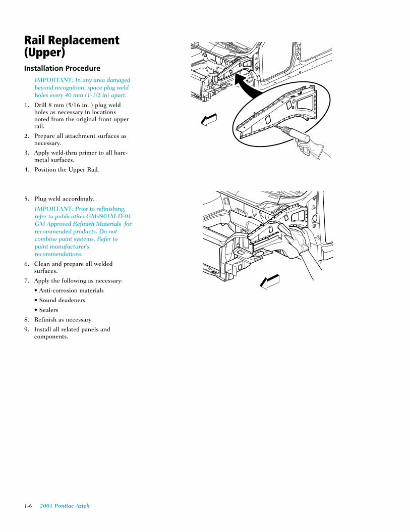
IMPORTANT: In any area damagedbeyond recognition, space plug weldholes every 40 mm (1-1/2 in) apart.
1. Drill 8 mm (5/16 in. ) plug weldholes as necessary in locationsnoted from the original front upperrail.
2. Prepare all attachment surfaces asnecessary.
3. Apply weld-thru primer to all bare-metal surfaces.
4. Position the Upper Rail.
5. Plug weld accordingly.
IMPORTANT: Prior to refinishing,refer to publication GM4901M-D-01GM Approved Refinish Materials forrecommended products. Do notcombine paint systems. Refer topaint manufacturer’srecommendations.
6. Clean and prepare all weldedsurfaces.
7. Apply the following as necessary:
• Anti-corrosion materials
• Sound deadeners
• Sealers
8. Refinish as necessary.
9. Install all related panels andcomponents.
2001 Pontiac Aztek 1-7
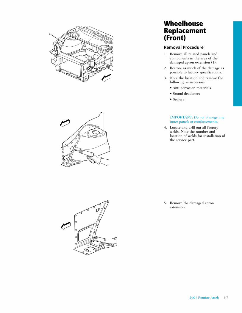
WheelhouseReplacement(Front)Removal Procedure1. Remove all related panels and
components in the area of thedamaged apron extension (1).
2. Restore as much of the damage aspossible to factory specifications.
3. Note the location and remove thefollowing as necessary:
• Anti-corrosion materials
• Sound deadeners
• Sealers
IMPORTANT: Do not damage anyinner panels or reinforcements.
4. Locate and drill out all factorywelds. Note the number andlocation of welds for installation ofthe service part.
5. Remove the damaged apronextension.
1

1-8 2001 Pontiac Aztek
WheelhouseReplacement(Front)Installation Procedure
IMPORTANT: In any area damagedbeyond recognition, space plug weldholes every 40 mm (1-1/2 in) apart.
1. Drill 8 mm (5/16 in.) plug weldholes in the service part asnecessary in the locations notedfrom the original panel.
2. Prepare all attachment surfaces asnecessary.
IMPORTANT: Prior to refinishing,refer to the publication GM4901M-D-01 GM Approved RefinishMaterials for recommendedproducts. Do not combine paintsystems. Refer to paintmanufacturer’s recommendations.
3. Apply weld-thru primer to all baremetal surfaces.
4. Position the apron extension.
5. Plug weld accordingly.
6. Clean and prepare all weldedsurfaces.
7. Apply the following as necessary:
• Anti-corrosion materials
• Sound deadening materials
• Sealers
8. Refinish as necessary.
9. Install all related panels andcomponents.
2001 Pontiac Aztek 1-9
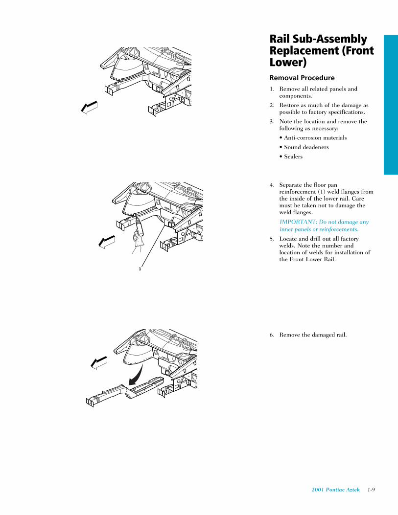
Rail Sub-AssemblyReplacement (FrontLower)Removal Procedure1. Remove all related panels and
components.
2. Restore as much of the damage aspossible to factory specifications.
3. Note the location and remove thefollowing as necessary:
• Anti-corrosion materials
• Sound deadeners
• Sealers
4. Separate the floor panreinforcement (1) weld flanges fromthe inside of the lower rail. Caremust be taken not to damage theweld flanges.
IMPORTANT: Do not damage anyinner panels or reinforcements.
5. Locate and drill out all factorywelds. Note the number andlocation of welds for installation ofthe Front Lower Rail.
6. Remove the damaged rail.
1

1-10 2001 Pontiac Aztek
Rail Sub-AssemblyReplacement (FrontLower)Installation Procedure
1. Prepare the mating surfaces of thefloor pan reinforcement (1).
2. Turn the weld flanges outward (2)to be welded to the front lower rail.
3. Drill 8 mm (5/16 in.) plug weldholes as necessary in locationsnoted from removal.
IMPORTANT: In any area damagedbeyond recognition, space plug weldholes every 40 mm (1-1/2 in.) apart.
4. Drill 8 mm (5/16 in.) plug weldholes as necessary in locationsnoted from the original panel.
5. Prepare all attachment surfaces asnecessary.
6. Apply weld-thru primer to all bare-metal surfaces.
7. Position the service part
8. Plug weld accordingly.
IMPORTANT: Prior to refinishing,refer to publication GM4901M-D-01GM Approved Refinish Materials forrecommended products. Do notcombine paint systems. Refer topaint manufacturer’srecommendations.
9. Clean and prepare all weldedsurfaces.
10. Apply the following as necessary :
• Anti-corrosion materials
• Sound deadeners
• Sealers
11. Refinish as necessary.
12. Install all related panels andcomponents.
1
2
2001 Pontiac Aztek 1-11
Left Front LowerRail SectioningIMPORTANT: If the damage exceeds therecommended area for sectioning and therail cannot be straightened, the completerail must be replaced.
Sectioning procedures have beendeveloped to simplify repair of the lowerrails, providing the majority of thedamage can be returned to factoryspecifications. This allows the damagedfront section to be replaced withoutperforming a full rail replacement. Therails come as a complete assembly. Thefront portion of the rail and bumperbrackets are also serviced separately.IMPORTANT: Failure to follow theinstructions included with the service railmay lead to improper rail sectioning,which may compromise the structuralintegrity of the vehicle.
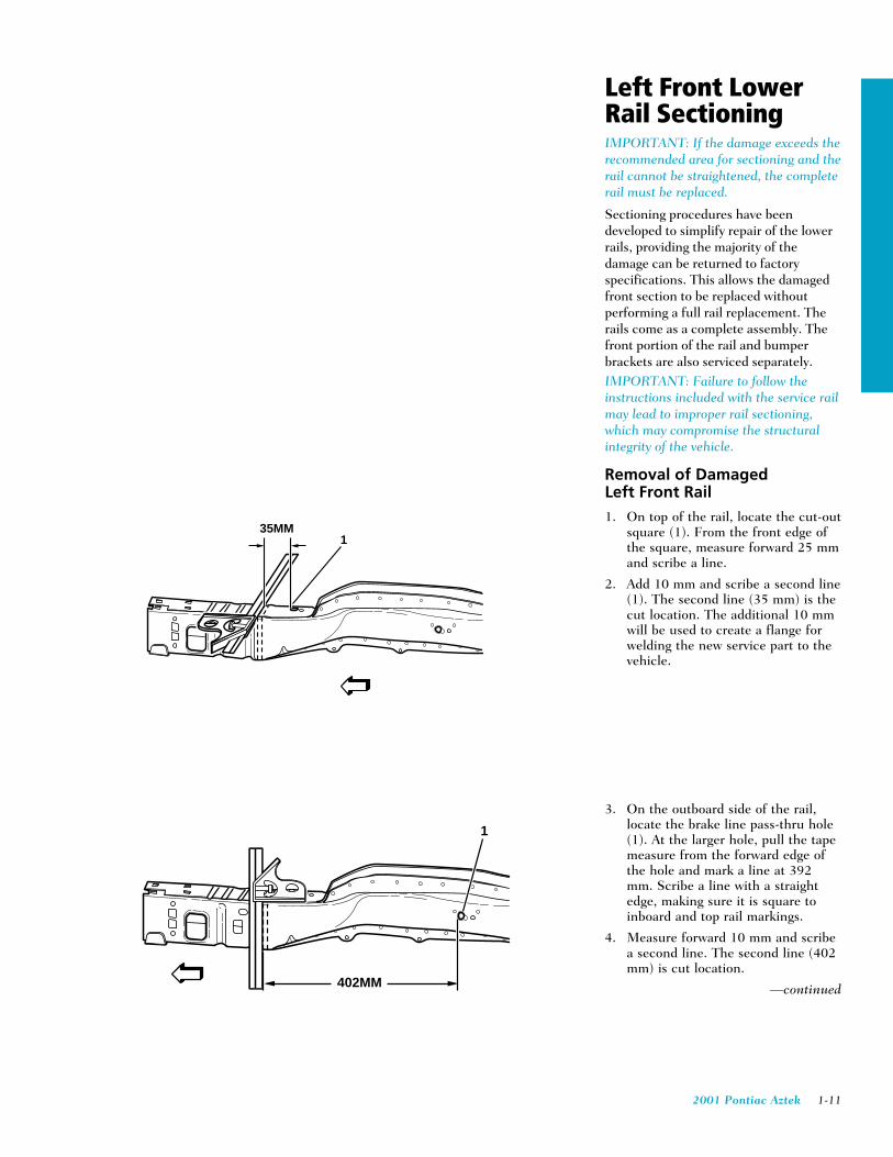
Removal of DamagedLeft Front Rail1. On top of the rail, locate the cut-out
square (1). From the front edge ofthe square, measure forward 25 mmand scribe a line.
2. Add 10 mm and scribe a second line(1). The second line (35 mm) is thecut location. The additional 10 mmwill be used to create a flange forwelding the new service part to thevehicle.
3. On the outboard side of the rail,locate the brake line pass-thru hole(1). At the larger hole, pull the tapemeasure from the forward edge ofthe hole and mark a line at 392mm. Scribe a line with a straightedge, making sure it is square toinboard and top rail markings.
4. Measure forward 10 mm and scribea second line. The second line (402mm) is cut location.
—continued
35MM1
1
402MM

1-12 2001 Pontiac Aztek
Removal of DamagedLeft Front Rail con’t5. Locate hole (1), on the inboard side
of the rail. Measure forward 140mm (5-1/2 in.) and mark thelocation. Scribe a straight line onthe rail.
6. Measure forward 10 mm (13/32 in.)and scribe a second line. Thesecond line [150 mm (5-29/32 in.)]is the cut location (2).
7. Make certain all three sides arealigned. Cut through three sides ofthe rail.
8. On the bottom of the damaged rail,scribe a line from the outboard tothe inboard cut locations and cutthe remainder of the rail (1) fromthe vehicle.
9. Remove the damaged section of rail.
150MM
1
2
1
(LEFT OUTBOARD)
2001 Pontiac Aztek 1-13
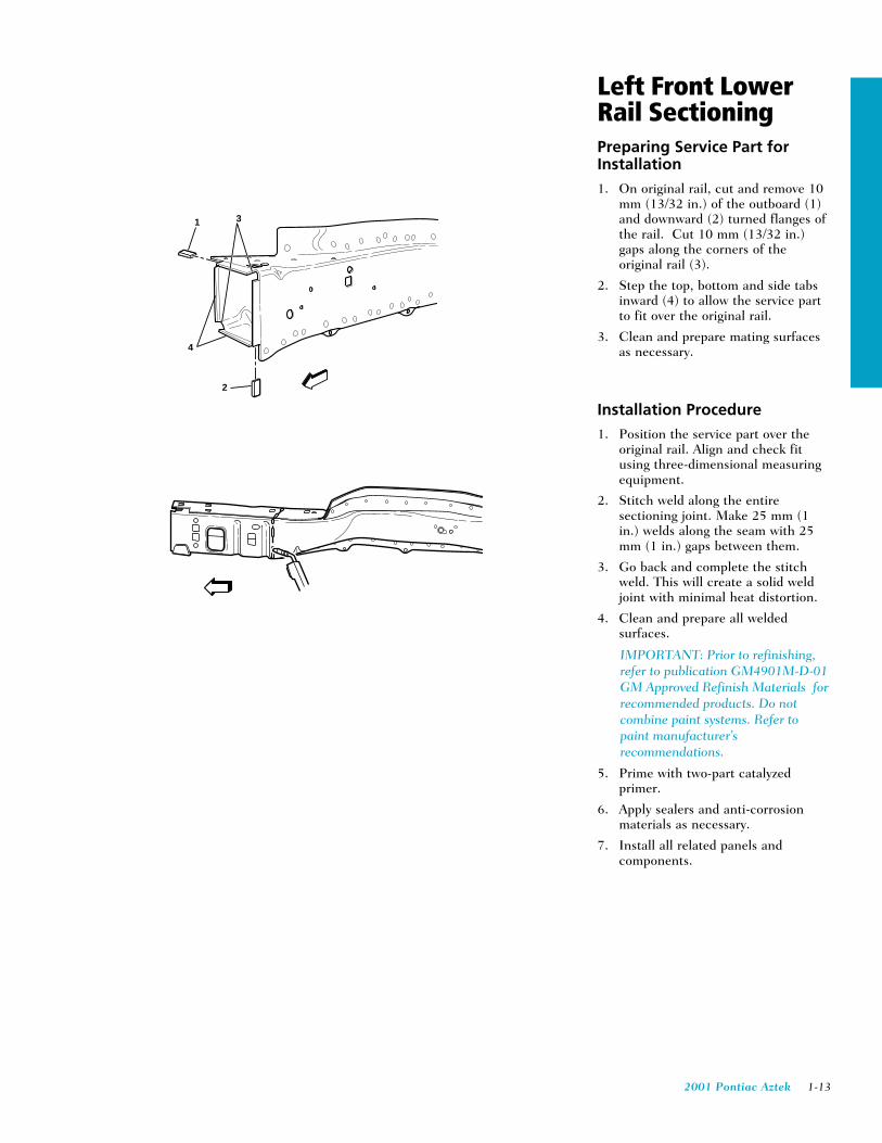
Left Front LowerRail SectioningPreparing Service Part forInstallation1. On original rail, cut and remove 10
mm (13/32 in.) of the outboard (1)and downward (2) turned flanges ofthe rail. Cut 10 mm (13/32 in.)gaps along the corners of theoriginal rail (3).
2. Step the top, bottom and side tabsinward (4) to allow the service partto fit over the original rail.
3. Clean and prepare mating surfacesas necessary.
Installation Procedure1. Position the service part over the
original rail. Align and check fitusing three-dimensional measuringequipment.
2. Stitch weld along the entiresectioning joint. Make 25 mm (1in.) welds along the seam with 25mm (1 in.) gaps between them.
3. Go back and complete the stitchweld. This will create a solid weldjoint with minimal heat distortion.
4. Clean and prepare all weldedsurfaces.
IMPORTANT: Prior to refinishing,refer to publication GM4901M-D-01GM Approved Refinish Materials forrecommended products. Do notcombine paint systems. Refer topaint manufacturer’srecommendations.
5. Prime with two-part catalyzedprimer.
6. Apply sealers and anti-corrosionmaterials as necessary.
7. Install all related panels andcomponents.
1
2
4
3
1-14 2001 Pontiac Aztek
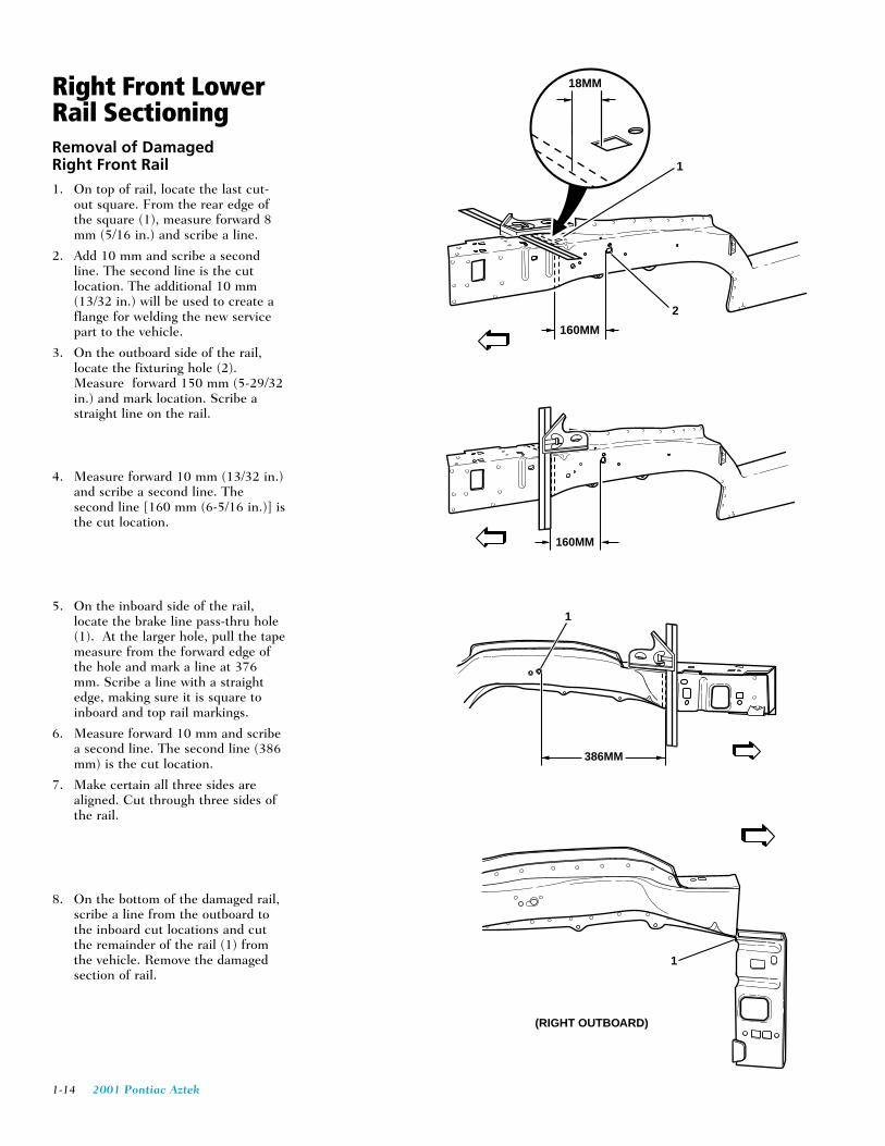
Right Front LowerRail SectioningRemoval of DamagedRight Front Rail1. On top of rail, locate the last cut-
out square. From the rear edge ofthe square (1), measure forward 8mm (5/16 in.) and scribe a line.
2. Add 10 mm and scribe a secondline. The second line is the cutlocation. The additional 10 mm(13/32 in.) will be used to create aflange for welding the new servicepart to the vehicle.
3. On the outboard side of the rail,locate the fixturing hole (2).Measure forward 150 mm (5-29/32in.) and mark location. Scribe astraight line on the rail.
4. Measure forward 10 mm (13/32 in.)and scribe a second line. Thesecond line [160 mm (6-5/16 in.)] isthe cut location.
5. On the inboard side of the rail,locate the brake line pass-thru hole(1). At the larger hole, pull the tapemeasure from the forward edge ofthe hole and mark a line at 376mm. Scribe a line with a straightedge, making sure it is square toinboard and top rail markings.
6. Measure forward 10 mm and scribea second line. The second line (386mm) is the cut location.
7. Make certain all three sides arealigned. Cut through three sides ofthe rail.
8. On the bottom of the damaged rail,scribe a line from the outboard tothe inboard cut locations and cutthe remainder of the rail (1) fromthe vehicle. Remove the damagedsection of rail.
1
2
160MM
18MM
160MM
1
(RIGHT OUTBOARD)
386MM
1

2001 Pontiac Aztek 1-15
Right Front LowerRail SectioningPreparing the UndamagedPortion of the Rail forInstallation1. On original rail, cut and remove 10
mm of the outboard (1) anddownward (2) turned flanges of therail. Cut 10 mm gaps along thecorners of the original rail.
2. Step the top, bottom and side tabsinward (3) to allow the service partto fit over the original rail.
3. Clean and prepare mating surfacesas necessary.
Installation Procedure
1. Position the service part over theoriginal rail. Align and check fitusing three-dimensional measuringequipment.
2. Stitch weld along the entiresectioning joint. Make 25 mm(1␣ in.) welds along the seam with 25mm (1 in.) gaps between them.
3. Go back and complete the stitchweld. This will create a solid weldjoint with minimal heat distortion.
4. Clean and prepare all weldedsurfaces.
IMPORTANT: Prior to refinishing,refer to publication GM4901M-D-01GM Approved Refinish Materials forrecommended products. Do notcombine paint systems. Refer topaint manufacturer’srecommendations.
5. Prime with two-part catalyzedprimer.
6. Apply sealers and anti-corrosionmaterials as necessary.
7. Install all related panels andcomponents.
1
2
4
3

1-16 2001 Pontiac Aztek
Door FrameSectioning—Outer(Front Hinge Pillar)Removal Procedure1. Remove all related panels and
components.
2. Restore as much of the damage aspossible to factory specifications.
3. Note the location and remove thefollowing as necessary:
• Anti-corrosion materials
• Sound deadeners (1)
• Sealers
IMPORTANT: Do not damage anyinner panels or reinforcements.
4. Cut the panel where sectioning is tobe performed.
5. Locate and drill out all factorywelds. Note the number andlocation of welds for installation ofthe service part.
6. Remove the damaged Front HingePillar.
1
1

2001 Pontiac Aztek 1-17
Door FrameSectioning—Outer(Front Hinge Pillar)Installation Procedure1. Cut the replacement service part in
corresponding locations to fit theremaining original panel. Thesectioning joint should be trimmedto allow a gap of one-and-one-halftimes the metal (1) thickness at thesectioning joint.
2. In the Front Hinge Pillar, create a50 mm (2 in.) backing plate (1)from the unused portion of theDoor Frame Opening. Trim thebacking plate as necessary to fitbehind the sectioning joint.
3. In the rocker locations, create a 100mm (4 in.) backing plate (2) fromthe unused portion of the doorframe opening. Trim the backingplate as necessary to fit behind thesectioning joint.
4. Drill 8 mm (5/16 in.) plug weldholes along the sectioning cut onthe remaining original part
—continued
1
1
2

1-18 2001 Pontiac Aztek
Door Frame Sectioning—Outer(Front Hinge Pillar)Installation Procedure con't
IMPORTANT: In any area damagedbeyond recognition, space plug weldholes every 40 mm (1-1/2 in.) apart.
5. Drill 8 mm (5/16 in.) plug weldholes as necessary in locationsnoted from the original panel.
6. Prepare all attachment surfaces asnecessary.
7. Apply weld-thru primer to all bare-metal surfaces.
8. Fit the backing plate (1) halfwayinto the sectioning joint (2). Clampand plug weld to the vehicle.
9. Align the Front Hinge Pillar usingthree-dimensional measuringequipment.
10. Plug weld accordingly.
11. To create a solid weld withminimum heat distortion, make 25mm (1 in.) stitch welds along theseam with 25 mm (1 in.) gapsbetween them. Then go back andcomplete the stitch weld.
IMPORTANT: Prior to refinishing,refer to publication GM 4901M-D-01 GM Approved Refinish Materialsfor recommended products. Do notcombine paint systems. Refer topaint manufacturer’srecommendations.
12. Clean and prepare all weldedsurfaces.
13. Apply the following as necessary:
• Anti-corrosion materials
• Sound deadeners (1)
• Sealers
14. Refinish as necessary.
15. Install all related panels andcomponents.
25MM(1/2 IN)
1
2
1
1
2001 Pontiac Aztek 1-19
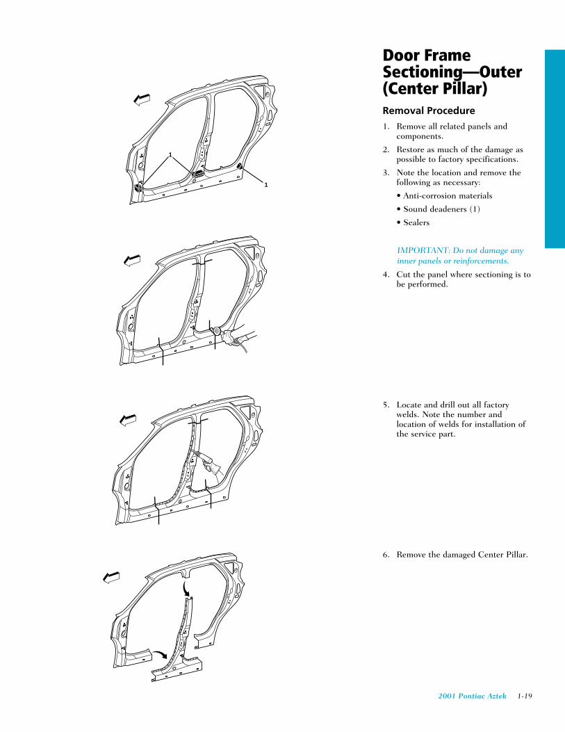
Door FrameSectioning—Outer(Center Pillar)Removal Procedure1. Remove all related panels and
components.
2. Restore as much of the damage aspossible to factory specifications.
3. Note the location and remove thefollowing as necessary:
• Anti-corrosion materials
• Sound deadeners (1)
• Sealers
IMPORTANT: Do not damage anyinner panels or reinforcements.
4. Cut the panel where sectioning is tobe performed.
5. Locate and drill out all factorywelds. Note the number andlocation of welds for installation ofthe service part.
6. Remove the damaged Center Pillar.
1
1
1-20 2001 Pontiac Aztek
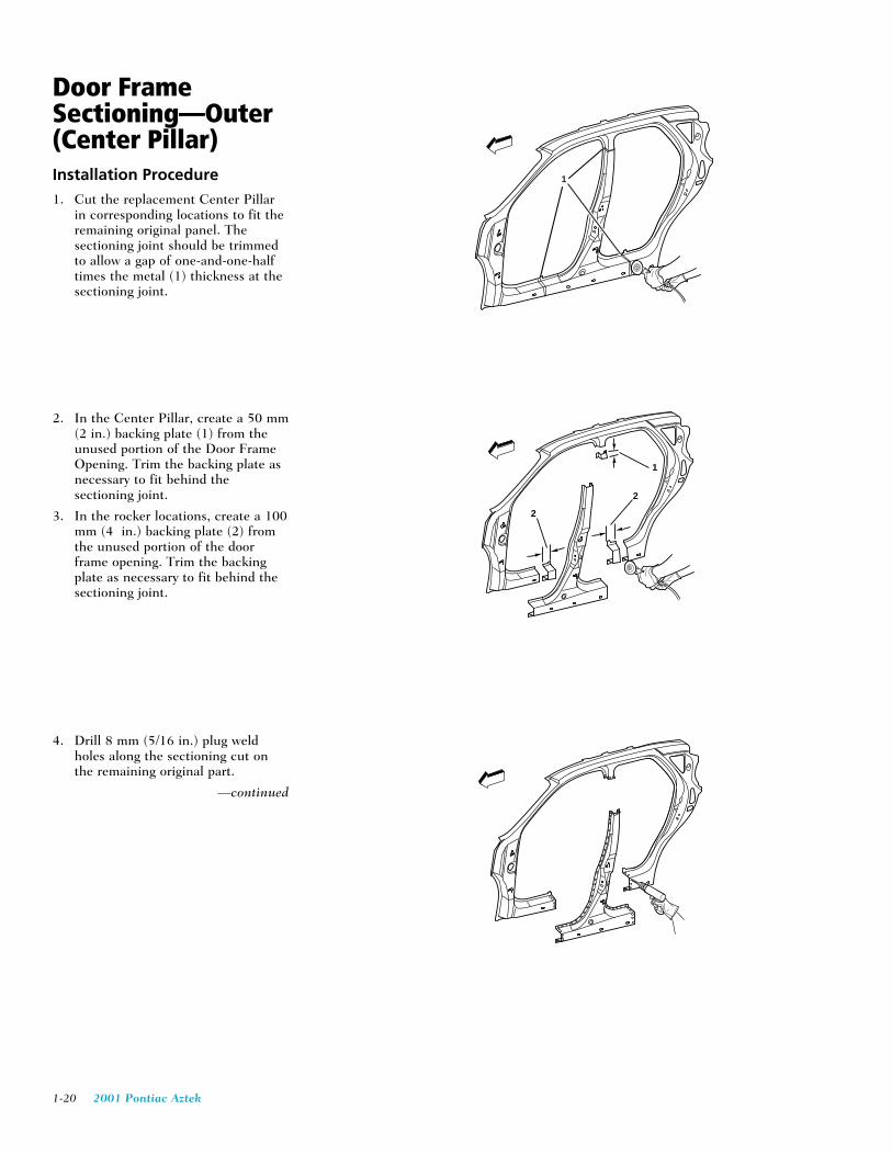
Door FrameSectioning—Outer(Center Pillar)Installation Procedure1. Cut the replacement Center Pillar
in corresponding locations to fit theremaining original panel. Thesectioning joint should be trimmedto allow a gap of one-and-one-halftimes the metal (1) thickness at thesectioning joint.
2. In the Center Pillar, create a 50 mm(2 in.) backing plate (1) from theunused portion of the Door FrameOpening. Trim the backing plate asnecessary to fit behind thesectioning joint.
3. In the rocker locations, create a 100mm (4 in.) backing plate (2) fromthe unused portion of the doorframe opening. Trim the backingplate as necessary to fit behind thesectioning joint.
4. Drill 8 mm (5/16 in.) plug weldholes along the sectioning cut onthe remaining original part.
—continued
1
1
2
2

2001 Pontiac Aztek 1-21
Door Frame Sectioning—Outer(Center Pillar)Installation Procedure con't
IMPORTANT: In any area damagedbeyond recognition, space plug weldholes every 40 mm (1-1/2 in.) apart.
5. Drill 8 mm (5/16 in.) plug weldholes as necessary in locationsnoted from the original panel.
6. Prepare all attachment surfaces asnecessary.
7. Apply weld-thru primer to all bare-metal surfaces.
8. Fit the backing plate (1) halfwayinto the sectioning joint (2) clampand plug weld to the vehicle.
9. Align the Center Pillar using three-dimensional measuring equipment.
10. Plug weld accordingly.
11. To create a solid weld withminimum heat distortion, make 25mm (1 in.) stitch welds along theseam with 25 mm (1 in.) gapsbetween them. Then go back andcomplete the stitch weld
IMPORTANT: Prior to refinishing,refer to publication GM 4901M-D-01 GM Approved Refinish Materialsfor recommended products. Do notcombine paint systems. Refer topaint manufacturer’srecommendations.
12. Clean and prepare all weldedsurfaces.
13. Apply the following as necessary:
• Anti-corrosion materials
• Sound deadeners (1)
• Sealers
14. Refinish as necessary.
15. Install all related panels andcomponents.
25MM(1 IN)
1
2
100mm(4 IN)
1
1

1-22 2001 Pontiac Aztek
Door FrameSectioning—Outer(Rear Lock Pillar)Removal Procedure1. Remove all related panels and
components.
2. Restore as much of the damage aspossible to factory specifications.
3. Note the location and remove thefollowing as necessary:
• Anti-corrosion materials
• Sound deadeners (1)
• Sealers
IMPORTANT: Do not damage anyinner panels or reinforcements.
4. Cut the panel where sectioning is tobe performed.
5. Locate and drill out all factorywelds. Note the number andlocation of welds for installation ofthe service part.
6. Remove the damaged Rear LockPillar.
1
1
2001 Pontiac Aztek 1-23
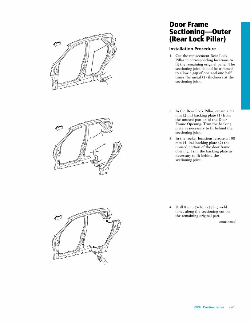
Door FrameSectioning—Outer(Rear Lock Pillar)Installation Procedure1. Cut the replacement Rear Lock
Pillar in corresponding locations tofit the remaining original panel. Thesectioning joint should be trimmedto allow a gap of one-and-one-halftimes the metal (1) thickness at thesectioning joint.
2. In the Rear Lock Pillar, create a 50mm (2 in.) backing plate (1) fromthe unused portion of the DoorFrame Opening. Trim the backingplate as necessary to fit behind thesectioning joint.
3. In the rocker locations, create a 100mm (4 in.) backing plate (2) theunused portion of the door frameopening. Trim the backing plate asnecessary to fit behind thesectioning joint.
4. Drill 8 mm (5/16 in.) plug weldholes along the sectioning cut onthe remaining original part.
—continued
1
1
2

1-24 2001 Pontiac Aztek
Door Frame Sectioning—Outer(Rear Lock Pillar)Installation Procedure con't
IMPORTANT: In any area damagedbeyond recognition, space plug weldholes every 40 mm (1-1/2in.) apart.
5. Drill 8 mm (5/16 in.) plug weldholes as necessary in locationsnoted from the original panel.
6. Prepare all attachment surfaces asnecessary.
7. Apply weld-thru primer to all bare-metal surfaces.
8. Fit the backing plate (1) halfwayinto the sectioning joint (2) clampand plug weld to the vehicle.
9. Align the Center Pillar using three-dimensional measuring equipment.
10. Plug weld accordingly.
11. To create a solid weld withminimum heat distortion, make 25mm (1 in.) stitch welds along theseam with 25 mm (1 in.) gapsbetween them. Then go back andcomplete the stitch weld.
IMPORTANT: Prior to refinishing,refer to publication GM4901M-D-01GM Approved Refinish Materials forrecommended products. Do notcombine paint systems. Refer topaint manufacturer’srecommendations.
12. Clean and prepare all weldedsurfaces.
13. Apply the following as necessary:
• Anti-corrosion materials
• Sound deadeners (1)
• Sealers
14. Refinish as necessary.
15. Install all related panels andcomponents.
25MM(1 IN)
1
2
100mm(4 IN)
1
1

2001 Pontiac Aztek 1-25
Door FrameSectioning—Outer(Rocker Sectioning)Removal Procedure1. Remove all related panels and
components.
2. Restore as much of the damage aspossible to factory specifications.
3. Note the location and remove thefollowing as necessary:
• Anti-corrosion materials
• Sound deadeners (1)
• Sealers
4. By measuring from the lower edgeof the guide hole (1) downward 30mm (1-3/16 in.), locate and markfor sectioning of the Front HingePillar and the Center Pillar.
5. With quarter panel removed (2),locate and mark for sectioning ofthe Rear Lock Pillar.
6. Scribe a line horizontally to therocker.
IMPORTANT: Do not damage anyinner panels or reinforcements.
7. Cut the panel where sectioning is tobe performed.
—continued
1
1
1
1
2
30mm(1 3/16 IN)
30mm(1 3/16 IN)
1-26 2001 Pontiac Aztek
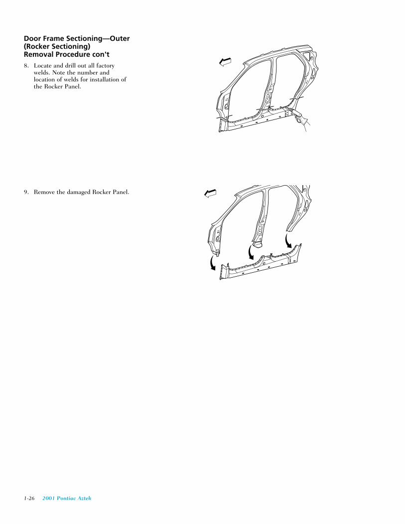
Door Frame Sectioning—Outer(Rocker Sectioning)Removal Procedure con't8. Locate and drill out all factory
welds. Note the number andlocation of welds for installation ofthe Rocker Panel.
9. Remove the damaged Rocker Panel.

2001 Pontiac Aztek 1-27
Door FrameSectioning—Outer(Rocker Sectioning)Installation Procedure1. Cut the replacement service part in
corresponding locations to fit theremaining original panel. Thesectioning joint should be trimmedto allow a gap of one-and-one-halftimes the metal (1) thickness at thesectioning joint.
2. In the Rear Lock Pillar, create a 50mm (2 in.) backing plate (1) fromthe unused portion of the DoorFrame Opening. Trim the backingplate as necessary to fit behind thesectioning joint.
3. Use the lower hinge reinforcement(2) as the backing plate in the frontHinge Pillar and the Center HingePillar.
4. Drill 8 mm (5/16 in.) plug weldholes along the sectioning cut onthe remaining original part.
IMPORTANT: In any area damagedbeyond recognition, space plug weldholes every 40 mm (1 in.) apart.
5. Drill 8 mm (5/16 in.) plug weldholes as necessary in locationsnoted from the original panel andalong the sectioning cut.
—continued
1
1
21

1-28 2001 Pontiac Aztek
Door Frame Sectioning—Outer(Rocker Sectioning)Installation Procedure con't6. Prepare all attachment surfaces as
necessary.
7. Apply weld-thru primer to all bare-metal surfaces.
8. Fit the backing plate (1) halfwayinto the sectioning joint (2). Clampand plug weld to the vehicle.
9. Align the Rocker Panel using three-dimensional measuring equipment.
10. Plug weld accordingly.
11. To create a solid weld withminimum heat distortion, make 25mm (1 in.) stitch welds along theseam with 25 mm (1 in.) gapsbetween them. Then go back andcomplete the stitch weld.
IMPORTANT: Prior to refinishing,refer to publication GM4901M-D-01GM Approved Refinish Materials forrecommended products. Do notcombine paint systems. Refer topaint manufacturer’srecommendations.
12. Clean and prepare all weldedsurfaces.
13. Apply the following as necessary:
• Anti-corrosion materials
• Sound deadeners (1)
• Sealers
14. Refinish as necessay.
15. Install all related panels andcomponents.
25MM(1 IN)
1
2
1
1
1

2001 Pontiac Aztek 1-29
Roof OuterReplacementRemoval Procedure1. Remove all related panels and
components.
2. Restore as much of the damage aspossible to factory specifications.
3. Note the location and remove thefollowing as necessary:
• Sealers
• Sound deadeners
• Anti-corrosion materials
IMPORTANT: Do not damage anyinner panels or reinforcements.
4. Locate and drill out all factorywelds. Note the number andlocation of welds for installation ofthe roof panel.
5. Remove the damaged roof panel.
1-30 2001 Pontiac Aztek
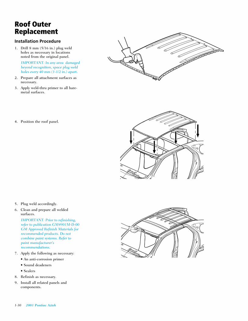
Roof OuterReplacementInstallation Procedure1. Drill 8 mm (5/16 in.) plug weld
holes as necessary in locationsnoted from the original panel.
IMPORTANT: In any area damagedbeyond recognition, space plug weldholes every 40 mm (1-1/2 in.) apart.
2. Prepare all attachment surfaces asnecessary.
3. Apply weld-thru primer to all bare-metal surfaces.
4. Position the roof panel.
5. Plug weld accordingly.
6. Clean and prepare all weldedsurfaces.
IMPORTANT: Prior to refinishing,refer to publication GM4901M-D-00GM Approved Refinish Materials forrecommended products. Do notcombine paint systems. Refer topaint manufacturer’srecommendations.
7. Apply the following as necessary:
• An anti-corrosion primer
• Sound deadeners
• Sealers
8. Refinish as necessary.
9. Install all related panels andcomponents.

2001 Pontiac Aztek 1-31
Quarter PanelReplacementRemoval Procedure1. Remove all related panels and
components.
2. Restore as much of the damage aspossible to factory specifications.
3. Note the location and remove thefollowing as necessary:
• Sealers
• Sound deadeners (1)
• Anti-corrosion materials
IMPORTANT: Do not damage anyinner panels or reinforcements.
4. Cut the quarter panel wheresectioning is to be performed (1).
5. Locate and drill out all factorywelds. Note the number andlocation of welds for installation ofthe service part.
6. Remove the damaged quarter.
1
1
1 1

1-32 2001 Pontiac Aztek
Quarter PanelReplacementInstallation Procedure1. Cut the replacement quarter panel
in corresponding locations to fit theremaining original panel. Thesectioning joint should be trimmedto allow a gap of one-and-one-halftimes the metal thickness at thesectioning joint.
2. Create a 50 mm (2 in.) backingplate from the unused portion of theservice part Trim the backing plateas necessary to fit behind thesectioning joint.
3. Drill 8 mm (5/16 in.) plug weldholes (1) along the sectioning cuton the remaining original part (2).
IMPORTANT: In any area damagedbeyond recognition, space plug weldholes every 40 mm (1-1/2 in.) apart.
4. Drill 8 mm (5/16 in.) plug weldholes in the service part asnecessary in the locations notedfrom the original panel and alongthe sectioning cut.
5. Prepare all attachment surfaces asnecessary.
IMPORTANT: Prior to refinishing,refer to publication GM4901M-D-01GM Approved Refinish Materials forrecommended products. Do notcombine paint systems. Refer topaint manufacturer’srecommendations.
6. Apply weld-thru primer to all bare-metal surfaces.
—continued
50MM(2 IN)
50MM(2 IN)
25MM(1 IN)
1
2

2001 Pontiac Aztek 1-33
Quarter Panel ReplacementInstallation Procedure con't7. Fit the backing plate halfway into
the sectioning joint, clamp and plugweld to the vehicle.
CAUTION: THE FUEL FILLEROPENING MUST BE PROPERLYSEALED PRIOR TOPOSITIONING THE QUARTERPANEL. FAILURE TO PROPERLYSEAL THE QUARTER PANELCOULD RESULT IN EXHAUSTGAS LEAKAGE INTO THEINTERIOR OF THE VEHICLE,CAUSING PERSONAL INJURY.
8. Install GM P/N 12399117 SealingStrip between outer wheelhouse andquarter panel gas door pocket.
9. Install service quarter panel leavinga gap of one and one half times thethickness of the metal (1) at thesectioning joint.
10. Plug weld accordingly.
11. To create a solid weld withminimum heat distortion, make 25mm (1 in.) stitch welds along theseam with 25 mm (1 in.) gapsbetween them. Then go back andcomplete the stitch weld.
12. Clean and prepare all weldedsurfaces.
13. Apply the following as necessary:
• Anti-corrosion materials
• Sound deadeners
• Sealers
14. Refinish as necessary.
15. Install all related panels andcomponents.
1

1-34 2001 Pontiac Aztek
Rail Sectioning—RearRemoval Procedure
IMPORTANT: Rear rail sectioning mayrequire replacement of the rear floor panel.
1. Remove all related panels andcomponents.
2. Restore as much of the damage aspossible to factory specifications.
3. Note the location and remove thefollowing as necessary:
• Anti-corrosion materials
• Sound deadeners
• Sealers
IMPORTANT: Do not damage anyinner panels or reinforcements.
4. Perform the necessary procedures togain access to the rear rail.
5. Locate and drill out all factory welds.Note the number and location ofwelds for installation of the rear rail.
6. Mark the cut location by measuring 5mm (1/4 in.) from the rear edge of thesecond gauge hole rearward
7. Cut the rear rail section.
8. Remove the damaged rear rail section.
5mm(0.25 in)

2001 Pontiac Aztek 1-35
Rail Sectioning—RearInstallation Procedure1. Mark the cut location on the service
rail by measuring 5 mm (1/4 in.)from the front edge of the secondgauge hole forward.
2. Cut the rear rail service part.
3. Cut and remove 30 mm (1 and 3/16in.) from the flanges on either sideof the service section rail to create30 mm (1 and 3/16 in.) tabs (1).
4. Cut 5 mm (1/4 in.) wide gaps in thebottom corners (2).
5. Step the tabs inward (1) to allow theservice rail section to fit inside ofthe original rear rail.
IMPORTANT: The metal of the rearrail is of a heavy gauge. However, thetabs can be created using theappropriate tools.
6. Weld the tabs together along thelower edges (2).
—continued
5mm(0.25 in)
1
21
1
2

1-36 2001 Pontiac Aztek
Rail Sectioning—RearInstallation Procedure con’t
IMPORTANT: In any area damagedbeyond recognition, space plug weldholes every 40 mm (1-1/2 in.) apart.
7. Drill 8 mm (5/16 in.) plug weldholes along the sectioning cut onthe original rail. Locate these holes13 mm (1/2 in.) from the edge andspaced 40 mm (1/2 in.) apart.
8. Prepare all attachment surfaces asnecessary.
9. Turn the weld flange downward forrewelding (2).
10. Apply weld-thru primer to all bare-metal surfaces.
11. Align the service part over thestepped tab using three-dimensionalmeasuring equipment.
12. Plug weld accordingly.
—continued
12
2001 Pontiac Aztek 1-37
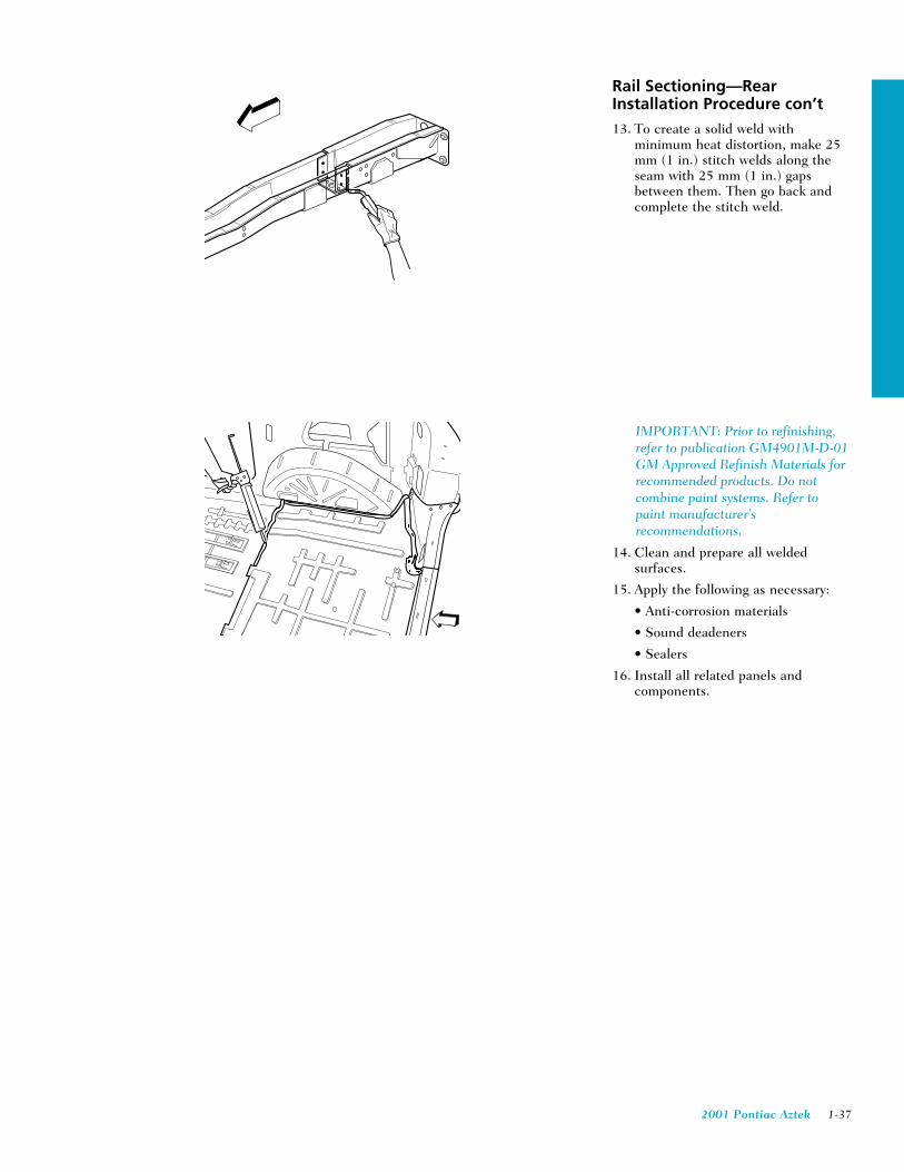
Rail Sectioning—RearInstallation Procedure con’t13. To create a solid weld with
minimum heat distortion, make 25mm (1 in.) stitch welds along theseam with 25 mm (1 in.) gapsbetween them. Then go back andcomplete the stitch weld.
IMPORTANT: Prior to refinishing,refer to publication GM4901M-D-01GM Approved Refinish Materials forrecommended products. Do notcombine paint systems. Refer topaint manufacturer’srecommendations.
14. Clean and prepare all weldedsurfaces.
15. Apply the following as necessary:
• Anti-corrosion materials
• Sound deadeners
• Sealers
16. Install all related panels andcomponents.
1-38 2001 Pontiac Aztek
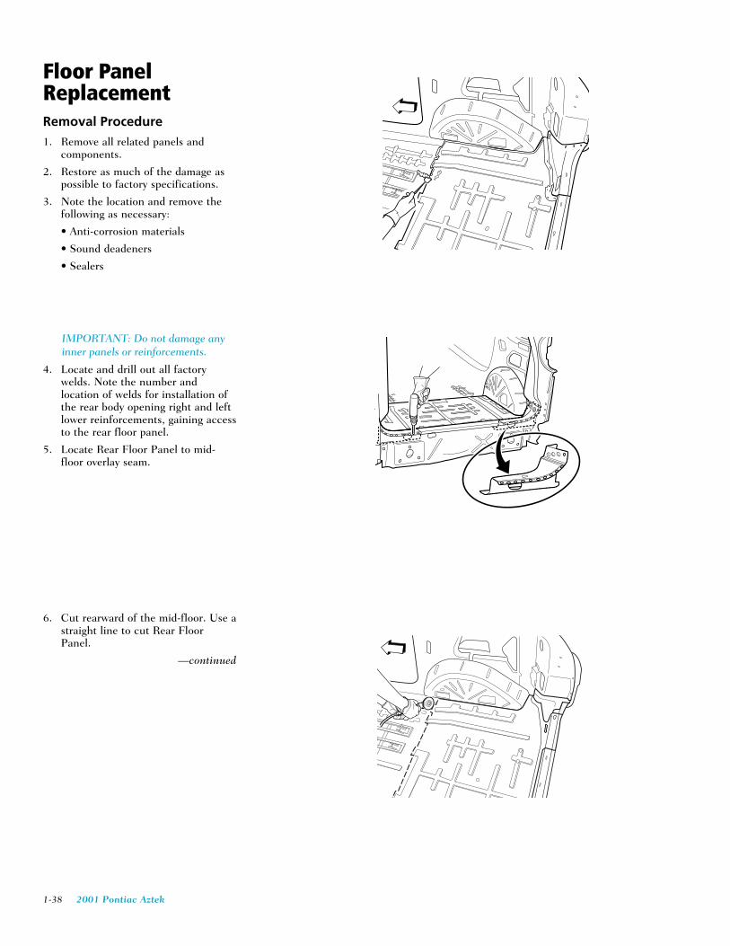
Floor PanelReplacementRemoval Procedure1. Remove all related panels and
components.
2. Restore as much of the damage aspossible to factory specifications.
3. Note the location and remove thefollowing as necessary:
• Anti-corrosion materials
• Sound deadeners
• Sealers
IMPORTANT: Do not damage anyinner panels or reinforcements.
4. Locate and drill out all factorywelds. Note the number andlocation of welds for installation ofthe rear body opening right and leftlower reinforcements, gaining accessto the rear floor panel.
5. Locate Rear Floor Panel to mid-floor overlay seam.
6. Cut rearward of the mid-floor. Use astraight line to cut Rear FloorPanel.
—continued

2001 Pontiac Aztek 1-39
Floor Panel ReplacementRemoval Procedure con’t7. Locate and drill out all factory
welds. Note the number andlocation of the welds for installationof the Rear Floor Panel.
8. Remove the damaged Rear FloorPanel.

1-40 2001 Pontiac Aztek
Floor PanelReplacementInstallation Procedure
IMPORTANT: In any area damagedbeyond recognition, space plug weldholes every 40 mm (1-1/2 in.) apart.
1. Drill 8 mm (5/16 in.) plug weldholes as necessary in locationsnoted from the original rear outerwheelhouse.
2. Drill 8 mm (5/16 in.) plug weldholes at the forward edge of the rearfloor panel.
3. Prepare all attachment surfaces asnecessary.
4. Apply weld-thru primer to all bare-metal surfaces.
5. Position the rear floor panel tooverlap the mid-floor panel.
6. Plug weld accordingly.
7. Drill 8 mm (5/16 in.) plug weldholes in the service part asnecessary in locations noted fromthe original panel.
8. Position right and left lowerreinforcements to the rear bodyopening.
9. Plug weld accordingly.

2001 Pontiac Aztek 1-41
Floor Panel ReplacementInstallation Procedure con’t
IMPORTANT: Prior to refinishing,refer to publication GM4901M-D-01GM Approved Refinish Materials forrecommended products. Do notcombine paint systems. Refer topaint manufacturer’srecommendations.
10. Clean and prepare all weldedsurfaces
11. Apply the following as necessary:
• Anti-corrosion materials
• Sound deadeners
• Sealers
12. Refinish as necessary.
13. Install all related panels andcomponents.

1-42 2001 Pontiac Aztek
Panel Replacement– Rear EndRemoval Procedure1. Remove all related panels and
components.
2. Restore as much of the damage aspossible to factory specifications.
3. Note the location and remove thefollowing as necessary:
• Anti-corrosion materials
• Sound deadeners
• Sealers
IMPORTANT: Do not damage anyinner panels or reinforcements.
4. Locate and drill out all factorywelds. Note the number andlocation of welds for installation ofthe rear body opening right and leftlower reinforcements, gaining accessto the rear floor panel.
5. Remove the Rear End Panel.
2001 Pontiac Aztek 1-43
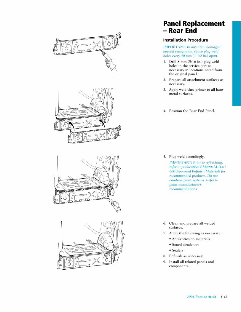
Panel Replacement– Rear EndInstallation Procedure
IMPORTANT: In any area damagedbeyond recognition, space plug weldholes every 40 mm (1-1/2 in.) apart.
1. Drill 8 mm (5/16 in.) plug weldholes in the service part asnecessary in locations noted fromthe original panel.
2. Prepare all attachment surfaces asnecessary.
3. Apply weld-thru primer to all bare-metal surfaces.
4. Position the Rear End Panel.
5. Plug weld accordingly.
IMPORTANT: Prior to refinishing,refer to publication GM4901M-D-01GM Approved Refinish Materials forrecommended products. Do notcombine paint systems. Refer topaint manufacturer’srecommendations.
6. Clean and prepare all weldedsurfaces.
7. Apply the following as necessary:
• Anti-corrosion materials
• Sound deadeners
• Sealers
8. Refinish as necessary.
9. Install all related panels andcomponents.

1-44 2001 Pontiac Aztek
WheelhouseReplacement –Rear OuterRemoval Procedure1. Remove all related panels and
components.
2. Restore as much of the damage aspossible to factory specifications.
3. Note the location and remove thefollowing as necessary:
• Anti-corrosion materials
• Sound deadeners (1)
• Sealers
IMPORTANT: Do not damage anyinner panels or reinforcements.
4. Using a suitable tool, trim off thedamaged rear wheelhouse.
IMPORTANT: The original weldflange can be used as an attachmentsurface for installation of the newwheelhouse.
5. Note the number and location ofwelds for installation of the RearOuter Wheelhouse.
6. Remove the damaged Rear OuterWheelhouse.
1

2001 Pontiac Aztek 1-45
WheelhouseReplacement –Rear OuterInstallation Procedure
IMPORTANT: In any area damagedbeyond recognition, space plug weldholes every 40 mm (1-1/2 in.) apart.
1. Drill 8 mm (5/16 in.) plug weldholes as necessary in locationsnoted from the original Rear OuterWheelhouse.
2. Prepare all attachment surfaces asnecessary.
3. Apply weld-thru primer to all bare-metal surfaces.
4. Position the Rear OuterWheelhouse.
5. Plug weld accordingly.
IMPORTANT: Prior to refinishing,refer to publication GM4901M-D-01GM Approved Refinish Materials forrecommended products. Do notcombine paint systems. Refer topaint manufacturer’srecommendations.
6. Clean and prepare all weldedsurfaces
7. Apply the following as necessary:
• Anti-corrosion materials
• Sound deadeners (1)
• Sealers
8. Refinish as necessary.
9. Install all related panels andcomponents.
11

1-46 2001 Pontiac Aztek
Aztek Plastic Panel Identification
2
3
3
11
1
1
1
1
1
1
1. TPO (Thermoplastic Olefin)
2. Xenoy
3. Polypropylene Energy Foam

2001 Pontiac Aztek 1-47
Aztek Metal Panel Identification
1
2
22
1
1
1
1
1
3
1
1
1. TSGS (Two Sided Galvanized Steel)
2. UHSS (Ultra High Strength Steel)
3. AL (Aluminum)

1-48 2001 Pontiac Aztek
1058
1052
1163
1456
982
994
944
1081
HEIGHT DATUMLINE
WIDTH
LENGTH
Ø
U
V
W
X
Y
Z
Ø
CL
T
91
18
1139
1122
1164
2100
7441117
1130
970768
807
808
801
807
807
789
1136
Body Dimensions
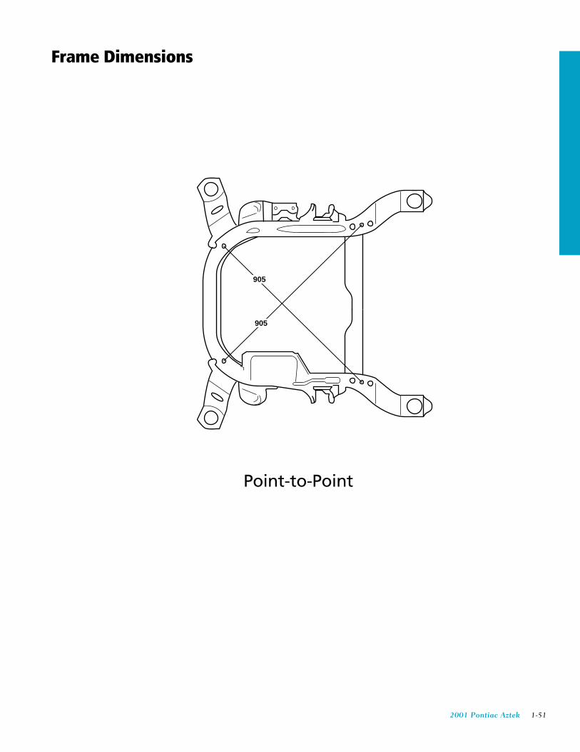
Point-to-Point
Body Side

2001 Pontiac Aztek 1-49
S
N
O
P
Q
R
Ø
CL CL
WIDTH
DATUMLINE
WIDTH
HEIGHT
LENGTH
Ø
355 716 687 747 740
355 716 687 747 740
925
1038
1019
852
470
433
206
1028
1159 1181
Body Dimensions
Engine Compartment

1-50 2001 Pontiac Aztek
D
CL
Ø
DATUMLINE
DRIVER SIDE
HEIGHT
WIDTH
WIDTH
LENGTH
Ø
CL
A
B
C E
F
G
H
I
J
K
L
M
450 542 538259
470
450432 432 432
432 432 432
432 432 432432432432
450
474
474
470
259
538542450
663
584
580
419
1105
953
845
411
411
113
175
415
406
1071
1425
1928
2555
2801
3062
462 504 528 567571
653
Body Measurements
Underbody
2001 Pontiac Aztek 1-51
905
905
Frame Dimensions
Point-to-Point