axial flow fan tip leakage flow control using tip platform ... _jf… · axial flow fan tip leakage...
TRANSCRIPT
1
aflissftfpgifflao
bstdsdIbRfl
edt
JrR
J
Downloa
Ali AktürkGraduate Research Assistant
e-mail: [email protected]
Cengiz Camci1
Professore-mail: [email protected]
Department of Aerospace Engineering,Turbomachinery Aero-Heat Transfer Laboratory,
Pennsylvania State University,University Park, PA 16802
Axial Flow Fan Tip Leakage FlowControl Using Tip PlatformExtensionsPerformance of an axial flow fan unit is closely related to its tip leakage mass flow rateand level of tip/casing interactions. The present experimental study uses a stereoscopicparticle image velocimeter to quantify the three dimensional mean flow observed near theblade tip, just downstream of a ducted fan unit. After a comprehensive description of theexit flow from the baseline fan, a number of novel tip treatments based on custom de-signed pressure side extensions are introduced. Various tip leakage mitigation schemesare introduced by varying the chordwise location and the width of the extension in thecircumferential direction. The current study shows a proper selection of the pressure sidebump location and width are the two critical parameters influencing the success of eachtip leakage mitigation approach. Significant gains in the axial mean velocity componentare observed when a proper pressure side tip extension is used. It is also observed that aproper tip leakage mitigation scheme significantly reduces the tangential velocity com-ponent near the tip of the axial fan blade. Reduced tip clearance related flow interactionsare essential in improving the energy efficiency of ducted fan systems. A reduction orelimination of the momentum deficit in tip vortices is also essential to reduce the adverseperformance effects originating from the unsteady and highly turbulent tip leakage flowsrotating against a stationary casing. �DOI: 10.1115/1.4001540�
IntroductionThe flow-field between the stationary casing and the rotor tip of
n axial fan is complex because of the interaction of the leakageow, the annulus wall boundary layer, and the rotor wake. An
nherent pressure difference between the pressure and suctionides of the blade tip generates a tip leakage flow that is respon-ible for a substantial portion of aerodynamic losses in axial flowans. The leakage flow also rolls into a highly three dimensionalip leakage vortex with significantly turbulent and unsteady floweatures in each passage. Tip leakage vortex is a complicated flowhenomenon that is one of the dominant mechanisms of noiseeneration by unsteady interactions in a turbomachinery system. Its also one of the major energy loss mechanisms for the axial flowan systems. Despite the close relation between the tip leakageow and the performance of axial fans, there has been limitedmount of information about the three dimensional flow structuref leakage vortex in open literature �1–4�.
Inoue et al. �5� made detailed flow measurements before andehind an axial flow rotor with different tip clearances. In theirtudy, they investigated the clearance effect on the behavior of theip leakage flow. Furukawa et al. �6� also investigated the break-own of the tip leakage vortex in a low speed axial flow compres-or. Reducing the tip leakage mass flow rate improves the aero-ynamic performance of axial flow fans and compressors.mplementation of treatments in the nonrotating part over thelade tip is also an efficient way of tip leakage flow reduction.eferences �7,8� investigate different casing treatments for axialow compressors.The wake developed from an axial flow fan has a strong influ-
nce on the system performance. It is a significant source of aero-ynamic loss and affects the efficiency and vibration characteris-ics. References �9–11� deal with extensive investigations of the
1Corresponding author.Contributed by the Fluids Engineering Division of ASME for publication in the
OURNAL OF FLUIDS ENGINEERING. Manuscript received July 17, 2009; final manuscripteceived February 20, 2010; published online May 14, 2010. Assoc. Editor: Zvi
usak.ournal of Fluids Engineering Copyright © 20
ded 17 Aug 2010 to 130.203.232.183. Redistribution subject to ASM
wake flow features such as mean velocities, turbulence, and decaycharacteristics on the turbomachinery performance.
Stereoscopic particle image velocimetry �SPIV� is an effectiveway of measuring all three velocity components of an instanta-neous flow-field over a selected area �12–16�. A comprehensivediscussion of the specific SPIV technique used in this paper isgiven by Kahveci and Camci �13–15�. Yoon and Lee �16� inves-tigated the flow structure around an axial flow fan using the SPIVtechnique. The time averaged results clearly show the evolutionand dissipation of tip vortices. Yen and Lin �17� analyzed the exitflow performance and properties of an axial flow fan with winglet-blades at various impeller angles using SPIV. The velocity profilesshow the most stable and the best fan performance resulting fromwinglet-blades, which increase the lift and reduce the drag. Wer-net et al. �18� made phase-locked three-dimensional digital par-ticle image velocimetry �DPIV� measurements near the tip regionof a low speed compressor rotor to characterize the behavior ofthe rotor tip clearance flow. A comparison of the DPIV measure-ments to the Navier–Stokes flow simulations was also done.
Corsini et al. �19–22� presented the results of a computationalstudy of an axial flow fan using “improved tip concepts.” The firsttwo end-plates were with constant and variable thickness distribu-tions, while the last two were designed by combining the end-plates with a stepped gap on the tip. The investigation was basedon a finite element Navier–Stokes solver for the physical interpre-tation of the detailed 3D leakage flow-field. The specific fan per-formance experiments have shown that the improved tip conceptsintroduced a small performance derating, but the efficiency curvesgive evidence of an improvement with a better peak performanceand a wider high efficiency curve toward the rotor stall margin.An aero-acoustic investigation showed a reduction in the rotoraero-acoustic signature.
The computationally predicted loss coefficients in Ref. �22�showed that the highest loss regions were always observed nearthe leakage vortex core. The computational comparison of me-chanical energy loss within the gap showed that the tip end-plateslead to a reduction in mechanical energy loss within the gap.
The present experimental study used stereoscopic particle im-
age velocimetry measurements at the exit of the seven-bladedMAY 2010, Vol. 132 / 051109-110 by ASME
E license or copyright; see http://www.asme.org/terms/Terms_Use.cfm
aup
f
2
mwSflsumtmrrtlppm
fTprfiOri
ter
0
Downloa
xial fan rotor. The fan rotor used for the experiment is widelysed in the air conditioning industry. All of the experiments wereerformed at constant rotational speed of the fan �859 rpm�.
The main objectives of the current study are summarized asollows:
• to investigate the characteristics of tip leakage flow and tipvortex in an axial flow fan using a high spatial resolutionand nonintrusive measurement technique; all three compo-nents of the tip region exit flow-field are measured using theSPIV technique
• to eliminate the adverse effects of the tip vortex by design-ing novel rotor tip geometries using pressure side extensions
• to reduce the local leakage mass flow rate and momentumdeficit in tip-vortex-driven flow structures
• to increase the energy efficiency of axial flow fan systems• to provide high quality phase-locked instantaneous flow data
for further studies in aero-acoustics of tip treated axial flowfans
Experimental Setup
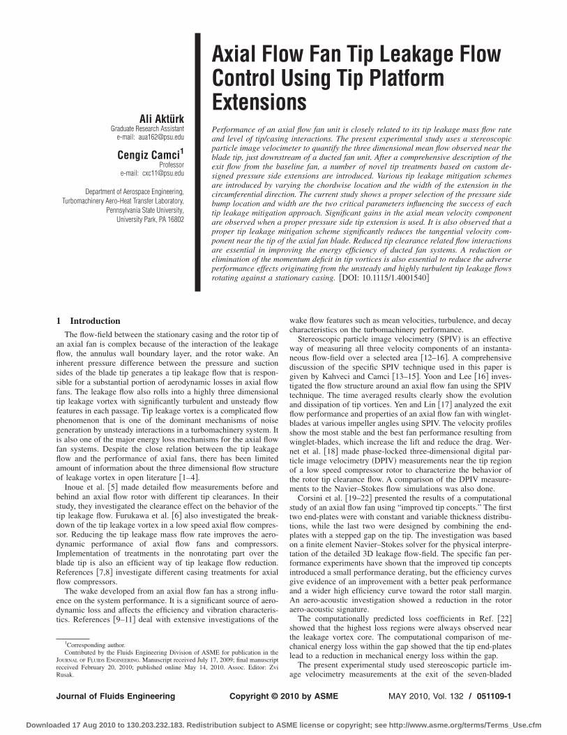
2.1 Test Rig. The test rig that consists of an axial flow fan, aock-up unit, and an electric drive system, as shown in Fig. 1,as designed to investigate the rotor exit flow phenomena using aPIV system. The setup also has provisions for seeding the fanow-field with a smoke generator using a fluidized bed. Themoke generator is located near the inlet section of the mock-upnit where a perforated plate controlling the fan loading isounted. The electric motor driving the fan rotor is speed con-
rolled by an AC inverter unit. The current phase-locked SPIVeasurements are triggered by using an optical once-per-
evolution device located near the hub of the rotor inlet. An infra-ed beam is reflected from a highly reflective surface attached tohe rotor hub. This once-per-revolution pulse provides a phase-ocked triggering of the SPIV data collection system. The relativeosition of the rotor can be adjusted accurately in relative to theosition of the laser light sheet that contains the rectangular SPIVeasurement area.
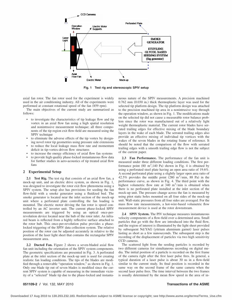
2.2 Ducted Fan. Figure 2 shows a seven-bladed axial flowan unit including the orientation of the SPIV system components.he geometric specifications are presented in Fig. 3. A perforatedlate at the inlet section of the mock-up unit is used for creatingealistic fan loading conditions. The tips of the blades are modi-ed through a removable “operation window,” as shown in Fig. 1.nly one blade tip out of seven blades is modified since the cur-
ent SPIV system is capable of measuring in the immediate vicin-
Fig. 1 Test rig and s
ty of a “selected” blade tip due to the phase-locked and instanta-
51109-2 / Vol. 132, MAY 2010
ded 17 Aug 2010 to 130.203.232.183. Redistribution subject to ASM
neous nature of the SPIV measurements. A precision machined0.762 mm �0.030 in.� thick thermoplastic layer was used for theselected tip platform design. The tip platform design was attachedto the precision machined tip area in a nonintrusive way throughthe operation window, as shown in Fig. 1. The modifications madeon the selected tip did not cause a measurable rotor balance prob-lem since the rotor was manufactured out of a relatively lightweight thermoplastic material. The current rotor blades have ser-rated trailing edges for effective mixing of the blade boundarylayers in the wake of each blade. The serrated trailing edges alsoprovide an effective mixing of individual tip vortices with thewakes of the seven blades in the rotating frame of reference. Itshould be noted that the comparison of the flow with serratedtrailing edges with a smooth trailing edge flow is not the subjectof the current paper.
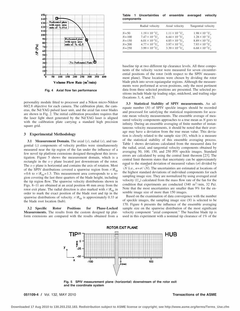
2.3 Fan Performance. The performance of the fan unit ismeasured under three different loading conditions. The first per-formance point �80 m3,140 Pa� shown in Fig. 4 is obtained byusing a perforated steel plate having an open area ratio of 19.6%.A second perforated plate using a slightly larger open area ratio of42.5% provides the middle point �280 m3 /min, 88 Pa� in theperformance curve, as shown in Fig. 4. The third point with thehighest volumetric flow rate at 340 m3 /min is obtained whenthere is no perforated plate installed at the inlet section of themock-up unit. The pressure change across the fan is measured byusing pitot static holes mounted on all four sides of the mock-upunit. Wall-static pressures from all four sides are averaged. For themass flow rate measurements, a hot-wire-based volumetric flowmeasurement device is used at the rotor downstream.
2.4 SPIV System. The PIV technique measures instantaneousvelocity components of a flow-field over a determined area. Smallparticles that go with the flow are introduced into the fluid flow,and the region of interest is illuminated by the light sheet providedby subsequent Nd:YAG �yttrium aluminum garnet� laser pulseslasting as short as a few nanoseconds. The subsequent step is therecording of the displacement of particles via two high sensitivityCCD cameras.
The scattered light from the seeding particles is recorded bytwo different cameras for simultaneous recording on digital me-dia. The initial position of a particle is recorded on the first frameof the camera right after the first laser pulse fires. In general, atypical duration of a laser pulse is about 30 ns in a flow-fieldsimilar to the current study. Its final position is recorded in thesame way on the second frame of the same camera when thesecond laser pulse fires. The time interval between the two frames
eoscopic SPIV setup
is usually determined by the mean flow speed in the area of in-
Transactions of the ASME
E license or copyright; see http://www.asme.org/terms/Terms_Use.cfm
vrpsbc�
acatccddbbtteesnhtiFdc
tP
J
Downloa
estigation. The order of magnitude of this adjustable time sepa-ation between the two frames is “microseconds.” Since the dis-lacement of the particle and the time interval between the twoubsequent laser pulses are known, the velocity of the particle cane calculated by the simple equation speed=distance / time. Aomprehensive explanation of this technique is given in Refs.12–16�.
In 3D PIV, there is an additional camera viewing the field fromdifferent angle. The two-dimensional image obtained by each
amera is slightly different from each other, and afterwards, theyre combined to produce the three-dimensional velocity informa-ion. Stereoscopic vision principles are instrumental in this pro-ess of combining the two planar images obtained from the twoameras viewing the same flow-field simultaneously. The data re-uction in a SPIV system requires the processing of four indepen-ent images from the two cameras. For 3D analysis, the 2D cali-ration images need to be converted additionally into the 3D datay a direct linear transform �DLT� model in order to calculate thehird component of the velocity. Correlation techniques are usedo obtain raw vector maps out of image pairs taken during thexperiments, and a number of calculation methods are used tovaluate these vector maps. In summary, the three dimensionalpace defined by the planar measurement area and the finite thick-ess of the laser sheet is analytically described in relation to theighly distorted images captured by the two CCD chips in each ofhe two cameras. The distortions observed on the planar CCDmages are generated by the angled position of the two cameras.or example, a perfect cube in the measurement space is seen as aistorted cube in each one of the two images generated by the twoameras.
The current study uses high sensitivity cameras that are essen-ial in high speed flow measurements. Two of the 80C60 HiSense
Fig. 2 Axial flow fan as seen from the
exit plane and the SPIV system orientationIV/PLIF cameras with 1024�1280 pixels are used with 80N57
ournal of Fluids Engineering
ded 17 Aug 2010 to 130.203.232.183. Redistribution subject to ASM
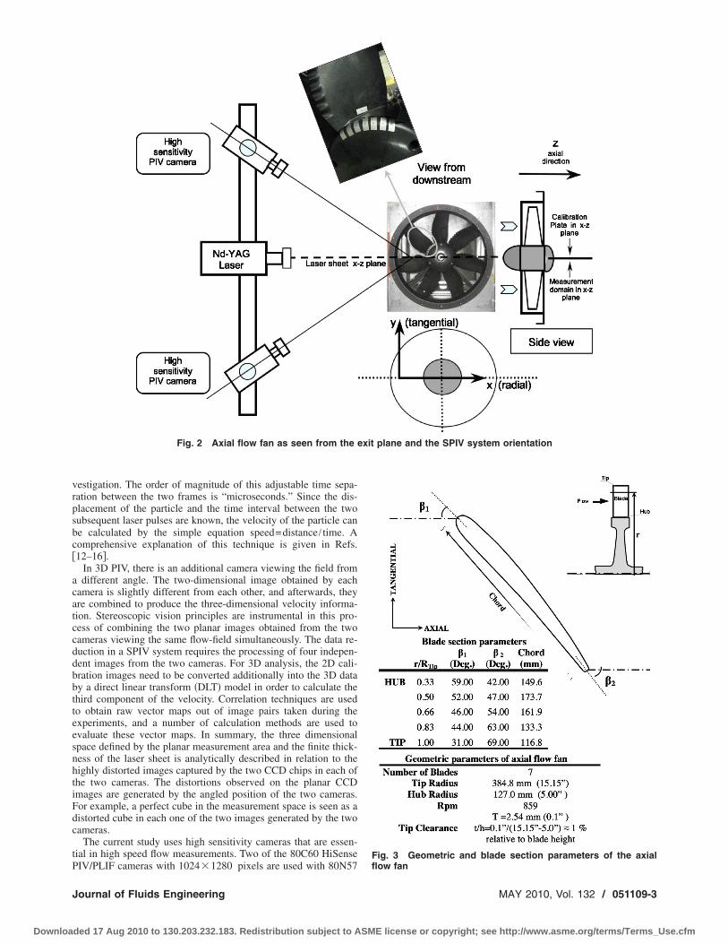
Fig. 3 Geometric and blade section parameters of the axial
flow fanMAY 2010, Vol. 132 / 051109-3
E license or copyright; see http://www.asme.org/terms/Terms_Use.cfm
p6eatws
3
gmftrTo=gtFrost
Mf
0
Downloa
ersonality module fitted to processor and a Nikon micro-Nikkor0/2.8 objective for each camera. The calibration plate, the cam-ras, the Nd:YAG pulsed laser unit, and the axial fan rotor bladesre shown in Fig. 2. The initial calibration procedure requires thathe laser light sheet generated by the Nd:YAG laser is alignedith the calibration plate carrying a standard high precision
quare grid.
Experimental Methodology
3.1 Measurement Domain. The axial �y�, radial �x�, and tan-ential �z� components of velocity profiles were simultaneouslyeasured near the tip region of the fan under the influence of a
ew novel tip platform extensions designed throughout this inves-igation. Figure 5 shows the measurement domain, which is aectangle in the x-y plane located just downstream of the rotor.he x-y plane is horizontal and contains the axis of rotation. Mostf the SPIV distributions covered a spanwise region from r /Rtip0.6 to r /Rtip=1.3. This measurement area corresponds to a re-ion covering the last three quarters of the blade height, includinghe tip region flow. The spanwise velocity distributions shown inigs. 8–11 are obtained at an axial position 46 mm away from theotor exit plane. The radial direction is also marked with r /Rtip inrder to mark the exact position of the blade root and tip in thepanwise distributions of velocity. r /Rtip is approximately 0.33 athe blade root location �hub�.
3.2 Specific Rotor Positions for Phase-Lockedeasurements. The results from the custom designed tip plat-
orm extensions are compared with the results obtained from a
Fig. 4 Axial flow fan performance
Fig. 5 SPIV measurement plane „ho
and the coordinate system51109-4 / Vol. 132, MAY 2010
ded 17 Aug 2010 to 130.203.232.183. Redistribution subject to ASM
baseline tip at two different tip clearance levels. All three compo-nents of the velocity vector were measured for seven circumfer-ential positions of the rotor �with respect to the SPIV measure-ment plane�. These locations were chosen by dividing the rotorblade pitch into seven equiangular regions. Although the measure-ments were performed at seven positions, only the most pertinentdata from three selected positions are presented. The selected po-sitions include blade tip leading edge, midchord, and trailing edge�locations 3, 4, and 5�.
3.3 Statistical Stability of SPIV measurements. An ad-equate number �N� of SPIV speckle images should be recordedand processed for satisfying the statistical requirements for accu-rate mean velocity measurements. The ensemble average of mea-sured velocity components approaches to a true mean as N goes toinfinity. During an ensemble averaging of finite number of instan-taneous velocity measurements, it should be noted that their aver-age may have a deviation from the true mean value. This devia-tion is closely related to the sample size �N�, which is a measureof the statistical stability of this ensemble averaging process.Table 1 shows deviations calculated from the measured data forthe radial, axial, and tangential velocity components obtained byaveraging 50, 100, 150, and 250 PIV speckle images. Standarderrors are calculated by using the central limit theorem �23�. Thecentral limit theorem states that uncertainty can be approximatelyequal to the standard deviation of measured values ��� divided by�N �i.e., �=� /�N�. The uncertainties are estimated at locations ofthe highest standard deviations of individual components for eachsampling image size. They are normalized by using averaged axialvelocity �Ua� calculated from the mass flow rate of the fan for thecondition that experiments are conducted �340 m3 /min, 32 Pa�.Note that the most uncertainties are smaller than 9% for the en-semble image size of more than 150 images.
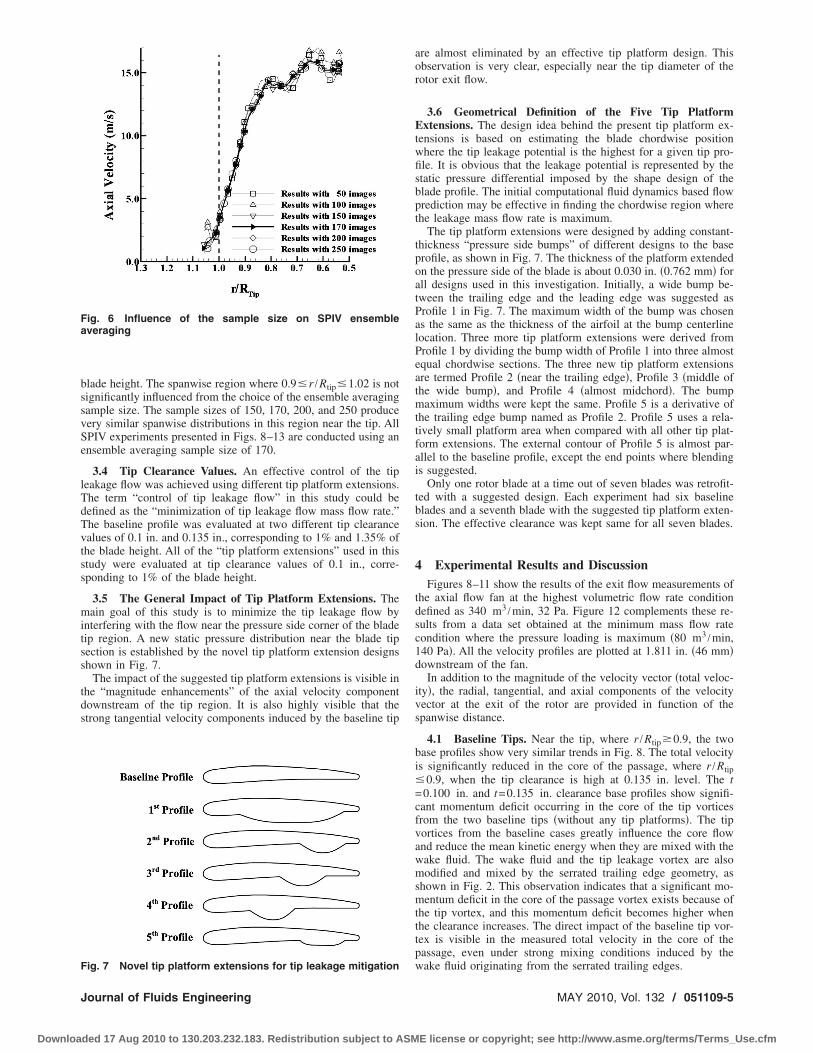
Based on the examination of data convergence with the numberof speckle images, the sampling image size �N� is selected to be170. Figure 6 presents the influence of the ensemble averagingsample size on the spanwise distribution of the most significantvelocity component “axial component.” The baseline blade tip isused in this experiment with a nominal tip clearance of 1% of the
ontal… downstream of the rotor exit
Table 1 Uncertainties of ensemble averaged velocitycomponents
Radial velocity Axial velocity Tangential velocity
N=50 1.19�10−1Ua 1.11�10−1Ua 1.98�10−1Ua
N=100 7.47�10−2Ua 6.44�10−2Ua 1.28�10−1Ua
N=150 6.01�10−2Ua 4.85�10−2Ua 8.89�10−2Ua
N=200 4.77�10−2Ua 3.97�10−2Ua 7.93�10−2Ua
N=250 3.99�10−2Ua 3.39�10−2Ua 6.68�10−2Ua
riz
Transactions of the ASME
E license or copyright; see http://www.asme.org/terms/Terms_Use.cfm
bssvSe
lTdTvtss
mitss
tds
Fa
F
J
Downloa
lade height. The spanwise region where 0.9�r /Rtip�1.02 is notignificantly influenced from the choice of the ensemble averagingample size. The sample sizes of 150, 170, 200, and 250 produceery similar spanwise distributions in this region near the tip. AllPIV experiments presented in Figs. 8–13 are conducted using annsemble averaging sample size of 170.
3.4 Tip Clearance Values. An effective control of the tipeakage flow was achieved using different tip platform extensions.he term “control of tip leakage flow” in this study could beefined as the “minimization of tip leakage flow mass flow rate.”he baseline profile was evaluated at two different tip clearancealues of 0.1 in. and 0.135 in., corresponding to 1% and 1.35% ofhe blade height. All of the “tip platform extensions” used in thistudy were evaluated at tip clearance values of 0.1 in., corre-ponding to 1% of the blade height.
3.5 The General Impact of Tip Platform Extensions. Theain goal of this study is to minimize the tip leakage flow by
nterfering with the flow near the pressure side corner of the bladeip region. A new static pressure distribution near the blade tipection is established by the novel tip platform extension designshown in Fig. 7.
The impact of the suggested tip platform extensions is visible inhe “magnitude enhancements” of the axial velocity componentownstream of the tip region. It is also highly visible that thetrong tangential velocity components induced by the baseline tip
ig. 6 Influence of the sample size on SPIV ensembleveraging
ig. 7 Novel tip platform extensions for tip leakage mitigation
ournal of Fluids Engineering
ded 17 Aug 2010 to 130.203.232.183. Redistribution subject to ASM
are almost eliminated by an effective tip platform design. Thisobservation is very clear, especially near the tip diameter of therotor exit flow.
3.6 Geometrical Definition of the Five Tip PlatformExtensions. The design idea behind the present tip platform ex-tensions is based on estimating the blade chordwise positionwhere the tip leakage potential is the highest for a given tip pro-file. It is obvious that the leakage potential is represented by thestatic pressure differential imposed by the shape design of theblade profile. The initial computational fluid dynamics based flowprediction may be effective in finding the chordwise region wherethe leakage mass flow rate is maximum.
The tip platform extensions were designed by adding constant-thickness “pressure side bumps” of different designs to the baseprofile, as shown in Fig. 7. The thickness of the platform extendedon the pressure side of the blade is about 0.030 in. �0.762 mm� forall designs used in this investigation. Initially, a wide bump be-tween the trailing edge and the leading edge was suggested asProfile 1 in Fig. 7. The maximum width of the bump was chosenas the same as the thickness of the airfoil at the bump centerlinelocation. Three more tip platform extensions were derived fromProfile 1 by dividing the bump width of Profile 1 into three almostequal chordwise sections. The three new tip platform extensionsare termed Profile 2 �near the trailing edge�, Profile 3 �middle ofthe wide bump�, and Profile 4 �almost midchord�. The bumpmaximum widths were kept the same. Profile 5 is a derivative ofthe trailing edge bump named as Profile 2. Profile 5 uses a rela-tively small platform area when compared with all other tip plat-form extensions. The external contour of Profile 5 is almost par-allel to the baseline profile, except the end points where blendingis suggested.
Only one rotor blade at a time out of seven blades was retrofit-ted with a suggested design. Each experiment had six baselineblades and a seventh blade with the suggested tip platform exten-sion. The effective clearance was kept same for all seven blades.
4 Experimental Results and DiscussionFigures 8–11 show the results of the exit flow measurements of
the axial flow fan at the highest volumetric flow rate conditiondefined as 340 m3 /min, 32 Pa. Figure 12 complements these re-sults from a data set obtained at the minimum mass flow ratecondition where the pressure loading is maximum �80 m3 /min,140 Pa�. All the velocity profiles are plotted at 1.811 in. �46 mm�downstream of the fan.
In addition to the magnitude of the velocity vector �total veloc-ity�, the radial, tangential, and axial components of the velocityvector at the exit of the rotor are provided in function of thespanwise distance.
4.1 Baseline Tips. Near the tip, where r /Rtip�0.9, the twobase profiles show very similar trends in Fig. 8. The total velocityis significantly reduced in the core of the passage, where r /Rtip�0.9, when the tip clearance is high at 0.135 in. level. The t=0.100 in. and t=0.135 in. clearance base profiles show signifi-cant momentum deficit occurring in the core of the tip vorticesfrom the two baseline tips �without any tip platforms�. The tipvortices from the baseline cases greatly influence the core flowand reduce the mean kinetic energy when they are mixed with thewake fluid. The wake fluid and the tip leakage vortex are alsomodified and mixed by the serrated trailing edge geometry, asshown in Fig. 2. This observation indicates that a significant mo-mentum deficit in the core of the passage vortex exists because ofthe tip vortex, and this momentum deficit becomes higher whenthe clearance increases. The direct impact of the baseline tip vor-tex is visible in the measured total velocity in the core of thepassage, even under strong mixing conditions induced by the
wake fluid originating from the serrated trailing edges.MAY 2010, Vol. 132 / 051109-5
E license or copyright; see http://www.asme.org/terms/Terms_Use.cfm

caon
0
Downloa
4.2 The Radial Component. The radial components for allases, as shown in Figs. 8–12, are all very small magnitudes,round �1 m/s. There is no significant influence on the magnitudef the baseline clearance or the type of tip treatment on the mag-itude of the radial component at all spanwise locations.
Fig. 8 Velocity profiles measuredclearances
Fig. 9 Velocity profiles measured a
51109-6 / Vol. 132, MAY 2010
ded 17 Aug 2010 to 130.203.232.183. Redistribution subject to ASM
4.3 Influence of Tip Platform Extensions on the TangentialComponent. When the axial velocity component in Fig. 9 is com-pared with the total velocity, a striking observation in the tip re-gion is apparent. The total velocity for the baseline tips is muchhigher than the axial component, where r /Rtip�1.05. However,
t location 3 for two different tip
3
a
t location 3 „340 m /min, 32 Pa…
Transactions of the ASME
E license or copyright; see http://www.asme.org/terms/Terms_Use.cfm
J
Downloa
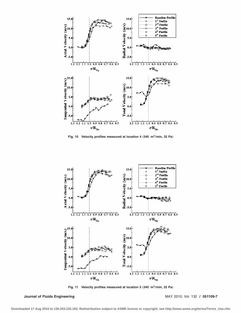
Fig. 10 Velocity profiles measured at location 4 „340 m3/min, 32 Pa…
3
Fig. 11 Velocity profiles measured at location 5 „340 m /min, 32 Pa…ournal of Fluids Engineering MAY 2010, Vol. 132 / 051109-7
ded 17 Aug 2010 to 130.203.232.183. Redistribution subject to ASME license or copyright; see http://www.asme.org/terms/Terms_Use.cfm
tt8sbcts
tdsnsie
aeabtrlflts
rpPobv
0
Downloa
he total velocity distribution for baseline tips is about the same ashe axial velocity component for the five treated tips shown in Fig.. Since the radial components are extremely small for all tiphapes, one can infer that the significant difference between theaseline and treated tips is due to a strong change in the tangentialomponent of the velocity vector. The distribution of the tangen-ial component shows a significant difference in the whole mea-urement region, where r /Rtip�0.6.
One can conclude that there is a strong swirl component nearhe tip region when there is no tip treatment. The five treated tipsefined in Fig. 7 provide significant reduction in the amount ofwirl in the rotor exit flow. The reduction in the amount of swirlear the tip region is about 4–5 m/s, with the tip platform exten-ions shown in Fig. 7. The magnitude of the swirl component thats inherent to baseline tips is about one-third of the total velocityxisting in the core of passage.
4.4 Tip Platform Extensions With Highest Axial Velocityt Rotor Exit. Figure 9 shows that the five new tip platformxtension devices can be highly instrumental in reducing themount of swirl coming out of the rotor. This feature is certainly aenefit in terms of the energy efficiency of the axial flow fan whenhe fan is operated on its high volumetric flow rate �low pressureise� point. The tip platform extensions help to reduce the tipeakage mass flow rate and its momentum deficit via local viscousow modifications near the tip region. Profiles 1 and 2 provide the
wo profiles with the highest total velocity in the core of the pas-age exit flow.
4.5 The Optimal Tip Platform Design. The experimentalesults suggest that the “maximum width” of the bump is an im-ortant parameter in designing the tip desensitization geometry.rofiles 2 and 5 cover almost the same chordwise locations. Thenly difference between the two is the maximum width of theump. Figures 8–10 clearly show that the recovery of the axial
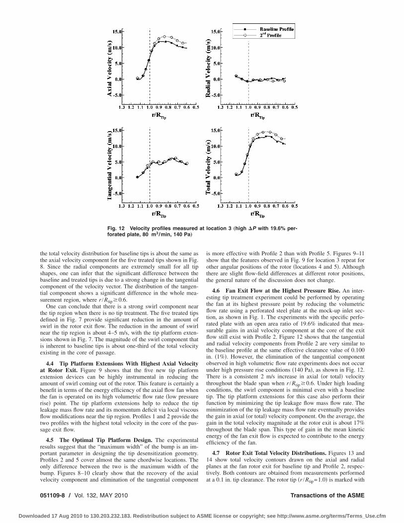
Fig. 12 Velocity profiles measuredforated plate, 80 m3/min, 140 Pa…
elocity component and elimination of the tangential component
51109-8 / Vol. 132, MAY 2010
ded 17 Aug 2010 to 130.203.232.183. Redistribution subject to ASM
is more effective with Profile 2 than with Profile 5. Figures 9–11show that the features observed in Fig. 9 for location 3 repeat forother angular positions of the rotor �locations 4 and 5�. Althoughthere are slight flow-field differences at different rotor positions,the general nature of the discussion does not change.
4.6 Fan Exit Flow at the Highest Pressure Rise. An inter-esting tip treatment experiment could be performed by operatingthe fan at its highest pressure point by reducing the volumetricflow rate using a perforated steel plate at the mock-up inlet sec-tion, as shown in Fig. 1. The experiments with the specific perfo-rated plate with an open area ratio of 19.6% indicated that mea-surable gains in axial velocity component at the core of the exitflow still exist with Profile 2. Figure 12 shows that the tangentialand radial velocity components from Profile 2 are very similar tothe baseline profile at the same effective clearance value of 0.100in. �1%�. However, the elimination of the tangential componentobserved in high volumetric flow rate experiments does not occurunder high pressure rise conditions �140 Pa�, as shown in Fig. 12.There is a consistent 2 m/s increase in axial �or total� velocitythroughout the blade span when r /Rtip�0.6. Under high loadingconditions, the swirl component is minimal even with a baselinetip. The tip platform extensions for this case also perform theirfunction by minimizing the tip leakage flow mass flow rate. Theminimization of the tip leakage mass flow rate eventually providesthe gain in axial �or total� velocity component. On the average, thegain in the total velocity magnitude at the rotor exit is about 17%throughout the blade span. This type of gain in the mean kineticenergy of the fan exit flow is expected to contribute to the energyefficiency of the fan.
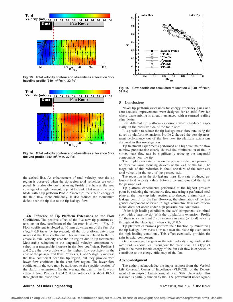
4.7 Rotor Exit Total Velocity Distributions. Figures 13 and14 show total velocity contours drawn on the axial and radialplanes at the fan rotor exit for baseline tip and Profile 2, respec-tively. Both contours are obtained from measurements performed
location 3 „high �P with 19.6% per-
atat a 0.1 in. tip clearance. The rotor tip �r /Rtip=1.0� is marked with
Transactions of the ASME
E license or copyright; see http://www.asme.org/terms/Terms_Use.cfm
trpcbtd
CtFricMsactlctet
Ft
Fb
J
Downloa
he dashed line. An enhancement of total velocity near the tipegion is observed when the tip region total velocities are com-ared. It is also obvious that using Profile 2 enhances the areaoverage of a high momentum jet at the exit. That means the rotorlade with a tip platform Profile 2 increases the kinetic energy ofhe fluid flow more efficiently. It also reduces the momentumeficit near the tip due to the tip leakage flow.
4.8 Influence of Tip Platform Extensions on the Flowoefficient. The positive effect of the five new tip platform ex-
ensions on flow coefficient of the fan rotor is shown in Fig. 15.low coefficient is plotted at 46 mm downstream of the fan. For/Rtip�0.9 �near the tip region�, all the tip platform extensionsncreased the flow coefficient. This increase is related to the in-rease in axial velocity near the tip region due to tip treatments.easurable reduction in the tangential velocity component re-
ulted in a measurable increase in the flow coefficient. Profiles 1nd 2 are the two profiles with the highest flow coefficient in theore of the passage exit flow. Profiles 3, 4, and 5 slightly increasehe flow coefficient near the tip region, but they provide withower flow coefficient in the core flow region. The lower flowoefficient in the core may be attributed to the specific location ofhe platform extensions. On the average, the gain in the flow co-fficient from Profiles 1 and 2 at the rotor exit is about 18.6%
ig. 14 Total velocity contour and streamlines at location 3 forhe 2nd profile „340 m3/min, 32 Pa…
ig. 13 Total velocity contour and streamlines at location 3 foraseline profile „340 m3/min, 32 Pa…
hroughout the blade span.
ournal of Fluids Engineering
ded 17 Aug 2010 to 130.203.232.183. Redistribution subject to ASM
5 ConclusionsNovel tip platform extensions for energy efficiency gains and
aero-acoustic improvements were designed for an axial flow fanwhere wake mixing is already enhanced with a serrated trailingedge design.
Five different tip platform extensions were introduced espe-cially on the pressure side of the fan blades.
It is possible to reduce the tip leakage mass flow rate using thenovel tip platform extensions. Profile 2 showed the best tip treat-ment performance out of the five new tip platform extensionsdesigned in this investigation.
Tip treatment experiments performed at a high volumetric flowrate/low pressure rise clearly showed the minimization of the tipvortex mass flow rate by significantly reducing the tangentialcomponents near the tip.
The tip platform extensions on the pressure side have proven tobe effective swirl reducing devices at the exit of the fan. Themagnitude of this reduction is about one-third of the rotor exittotal velocity in the core of the passage exit.
The reduction in the tip leakage mass flow rate produced en-hanced total velocity values between the midspan and the tip atthe passage exit.
Tip platform experiments performed at the highest pressurepoint by reducing the volumetric flow rate using a perforated steelplate at the mock-up inlet section also showed a significant tipleakage control for the fan. However, the elimination of the tan-gential component observed in high volumetric flow rate experi-ments does not occur under high pressure rise conditions.
Under high loading conditions, the swirl component is minimaleven with a baseline tip. With the tip platform extension “Profile2,” there is a consistent 2 m/s increase in axial �or total� velocitythroughout the blade span when r /Rtip�0.6.
Tip platform extensions perform their function by minimizingthe tip leakage flow mass flow rate near the blade tip even underthe high loading conditions. This effect eventually provides thegain in axial component.
On the average, the gain in the total velocity magnitude at therotor exit is about 17% throughout the blade span. This type ofgain in the mean kinetic energy of the fan exit flow is expected tocontribute to the energy efficiency of the fan.
AcknowledgmentThe authors acknowledge the major support from the Vertical
Lift Rotorcraft Center of Excellence �VLRCOE� of the Depart-ment of Aerospace Engineering at Penn State University. This
Fig. 15 Flow coefficient calculated at location 3 „340 m3/min,32 Pa…
research is partially funded by the U.S. government under Agree-
MAY 2010, Vol. 132 / 051109-9
E license or copyright; see http://www.asme.org/terms/Terms_Use.cfm
mt
N
R
0
Downloa
ent No. W911W6-06-2-0008. The authors also acknowledge theechnical support of Mr. H. Houtz during the experiments.
omenclature�1 � blade section inlet angle�2 � blade section exit angle
c � chord lengthCCD � charge-coupled device
� � experimental uncertaintyh � blade heightN � number of SPIV speckle images
PLIF � phosphorescence laser-induced fluoroscencep � static pressure � flow coefficient, =U /rr � radial position �r=0.0 at the axis of rotation�
Rhub � hub radiusRtip � tip radius
� � standard deviationt � effective tip clearance in inches
U � axial velocityV � radial velocityW � tangential velocity
Ua � averaged axial velocity � rotational speedx � radial direction, see Fig. 2y � axial direction, see Fig. 2z � tangential direction, see Fig. 2
eferences�1� Lee, G. H., Baek, J. H., and Myung, H. J., 2003, “Structure of Tip Leakage in
a Forward-Swept Axial-Flow Fan,” Flow, Turbul. Combust., 70, pp. 241–265.�2� Jang, C. M., Furukawa, M., and Inoue, M., 2001, “Analysis of Vertical Flow
Field in a Propeller Fan by LDV Measurements and LES—Parts I, II,” ASMEJ. Fluids Eng., 123, pp. 748–761.
�3� Storer, J. A., and Cumpsty, N. A., 1991, “Tip Leakage Flow in Axial Com-pressors,” ASME J. Turbomach., 113, pp. 252–259.
�4� Lakshminarayana, B., Zaccaria, M., and Marathe, B., 1995, “The Structure ofTip Clearance Flow in Axial Flow Compressors,” ASME J. Turbomach., 117,pp. 336–347.
�5� Inoue, M., Kuroumaru, M., and Furukawa, M., 1986, “Behavior of Tip Leak-age Flow Behind an Axial Compressor Rotor,” ASME J. Eng. Gas Turbines
Power, 108, pp. 7–14.51109-10 / Vol. 132, MAY 2010
ded 17 Aug 2010 to 130.203.232.183. Redistribution subject to ASM
�6� Furukawa, M., Inoue, M., Kuroumaru, M., Saik, K., and Yamada, K., 1999,“The Role of Tip Leakage Vortex Breakdown in Compressor Rotor Aerody-namics,” ASME J. Turbomach., 121, pp. 469–480.
�7� Fujita, H., and Takata, H., 1984, “A Study on Configurations of Casing Treat-ment for Axial Flow Compressors,” Bull. JSME, 27, pp. 1675–1681.
�8� Moore, R. D., Kovich, G., and Blade, R. J., 1971, “Effect of Casing Treatmenton Overall and Blade-Element Performance of a Compressor Rotor,” NASAReport No. TN-D6538.
�9� Reynolds, B., Lakshminarayana, B., and Ravindranath, A., 1979, “Character-istics of Near Wake of a Fan Rotor Blade,” AIAA J., 17, pp. 959–967.
�10� Ravindranath, A., and Lakshminarayana, B., 1980, “Mean Velocity and DecayCharacteristics of Near and Far-Wake of a Compressor Rotor Blade of Mod-erate Loading,” ASME J. Eng. Power, 102, pp. 535–547.
�11� Myung, H. J., and Baek, J. H., 1999, “Mean Velocity Characteristics Behind aForward-Swept Axial-Flow Fan,” JSME Int. J., Ser. B, 42, pp. 476–488.
�12� Adrian, R., 1991, “Particle Imaging Techniques for Experimental Fluid Me-chanics,” Annu. Rev. Fluid Mech., 23, pp. 261–304.
�13� Kahveci, H. S., and Camci, C., 2006, “Flow Around Helicopter Blade TipSections Using 2D Particle Image Velocimeter—Part I,” 11th InternationalSymposium on Transport Phenomena and Dynamics of Rotating Machinery�ISROMAC-11�, �136�.
�14� Kahveci, H. S., and Camci, C., 2006, “Flow Around Helicopter Blade TipSections Using a �3D� Stereoscopic Particle Image Velocimeter—Part II,” 11thInternational Symposium on Transport Phenomena and Dynamics of RotatingMachinery �ISROMAC-11�, �137�.
�15� Kahveci, H. S., 2004, “Implementation of a SPIV in Rotating Machinery In-cluding Helicopter Rotor Flows,” MS thesis, Pennsylvania State University,University Park, PA.
�16� Yoon, J. H., and Lee, S. J., 2004, “Exit Flow Field and Performance of AxialFlow Fans,” Exp. Therm. Fluid Sci., 28, pp. 791–802.
�17� Yen, S. C., and Lin, F. K. T., 2006, “Exit Flow Field and Performance of AxialFlow Fans,” ASME J. Fluids Eng., 128, pp. 332–340.
�18� Wernet, M. P., Van Zante, D., Strazisar, T. J., John, W. T., and Prahst, P. S.,2005, “Characterization of Tip Clearance Flow in an Axial Compressor Using3D DPIV,” Exp. Fluids, 39, pp. 743–753.
�19� Corsini, A., Perugini, B., Rispoli, F., Kinghorn, I., and Sheard, A. G., 2006,“Investigation on Improved Blade Tip Concept,” ASME Paper No. GT2006-90592.
�20� Corsini, A., Rispoli, F., and Sheard, A. G., 2006, “Development of ImprovedBlade Tip End-Plate Concepts for Low-Noise Operation in Industrial Fans,”Proceedings of the Conference on Modeling Fluid Flows CMMF06.
�21� Corsini, A., Perugini, B., Rispoli, F., Kinghorn, I., and Sheard, A. G., 2007,“Experimental and Numerical Investigations on Passive Devices for Tip-Clearance Induced Noise Reduction in Axial Flow Fans,” Proceedings of theSeventh European Conference on Turbomachinery.
�22� Corsini, A., Perugini, B., Rispoli, F., Sheard, A. G., and Kinghorn, I., 2007,“Aerodynamic Workings of Blade Tip End-Plates Designed for Low-NoiseOperation in Axial Flow Fans,” ASME Paper No. GT2007-27465.
�23� Ott, R. L., and Longnecker, M. T., 2000, An Introduction to Statistical Meth-
ods and Data Analysis, Duxbury, Los Altos, CA.Transactions of the ASME
E license or copyright; see http://www.asme.org/terms/Terms_Use.cfm