axell white paper-metro coverage in metros
DESCRIPTION
Axell White Paper-Metro Coverage in MetrosTRANSCRIPT

White Paper
AN OVERVIEW OF CELLULAR COVERAGE IN METROS

An Overview of Cellular Coverage in Metros
©Axell Wireless | www.axellwireless.com | [email protected] 2
Metro coverage solutions Seamless coverage is in demand in most places these days, including metros as passengers, train operators and emergency services expect to communicate at all times. Within the cellular market, subscribers expect to be able to make voice calls almost anywhere, and with the inception of the SMART phones, also surf the internet to keep up to date with friends on various social networking sites and of course respond to e-mails. The construction of Metro infrastructure varies widely so a flexible approach to the provision of communication enhancement systems is required. The typical requirement is to extend coverage from outside/above ground into confined areas, such as an underground station or tunnel. Axell Wireless has successful relationships with many metro authorities throughout Europe, the Far East and North America. We have a proven track record providing secure and reliable communication solutions for single or multiband systems that are used by the general public and the various public safety services alike. Axell Wireless now has equipment providing enhanced communications services in more than 70% of the worlds Metros.
Design criteria for metro coverage solutions When designing a metro system there are many variables that need to be considered. These include:
Available Solutions
Capacity Requirements
Location of equipment
Fibre Optic Availability
System expansion to support new technologies or additional capacity Over this document we will review the above topics in greater detail and discuss industry standard techniques used in the delivery of cellular into metro environments.
Available solutions
a) BTS based system In this type of solution, BTS equipment is housed at each Metro station and used to provide coverage within the station and the associated tunnels, via radiating cable and antenna. Where the distance between the stations is too long for this concept, the use of a second BTS for tunnel only coverage or a BTS with cascaded amplifiers may be used. Where multi operator systems are deployed a suitable equipment room with sufficient space, power and ventilation is needed to house the BTS of each operator and the associated combining systems.
b) Fibre Optic based system A Fibre Optic distributed system involves a series of base station ‘hotels’ where multiple base stations are housed along with an optical master unit (with the Axell Wireless systems this is called an OMU). The master unit is co-located with the BTS from the operator(s) and due to the flexibility of this approach can be positioned at a location some distance away from the metro. Fibre Optic is then used as the transmission medium to distribute cellular communications across the metro, with multiband repeaters at the remote locations, which in this case would be the metro stations and possibly tunnels. The use of Fibre Optic distribution for large metro and rail projects has become the recognised industry standard over the last few years due to the commercial and operational efficiencies and flexibility achieved in the metro environment.

An Overview of Cellular Coverage in Metros
©Axell Wireless | www.axellwireless.com | [email protected] 3
Capacity requirements Within a metro environment the actual capacity usage varies greatly between stations and the time of day. During rush hour, stations within the main business & commerce areas will be very busy, but once rush hour has abated more capacity may be required within the commercial areas. At weekend the main business areas will have limited demands, whilst the commercial areas and stations close to major sporting venues will see high demand.
Line Expected BH traffic (Erl) Total Traffic per line (Erl)
One
Station 1 7.9
Station 2 5.6
Station 3 6.3
Station 4 7.2
Station 5 6.1
Station 6 5.8
Station 7 11.2
Station 8 10.8
Station 9 10.1
Station 10 9.6
Station 11 13.2
Station 12 4.8
Station 13 4.9 103.5
Once this information is known, more detailed capacity planning can be undertaken allowing for anticipated Erlang requirements for both voice and data across the bands and technology being installed. BTS based coverage solution. With a BTS based system, the capacity allocated to any one station is static. Which means that the capacity from the BTS(s) installed at the station is dedicated to that specific station and associated tunnels. If there are high capacity needs in certain stations during the weekday, maybe in the central business district, higher capacity BTS may be deployed, thereby accommodating for peak traffic. However during the weekends this capacity is underutilised as users maybe at alternative venues.

An Overview of Cellular Coverage in Metros
©Axell Wireless | www.axellwireless.com | [email protected] 4
Table below depicts a typical capacity distribution in a metro using BTSs for coverage at every station. In this example a total of Er 80 is used in the metro and 50 TRUs deployed. It is interesting to see how static the system is and that some stations suffer from congestion and others have hardly any traffic.
Cell name TCH Traffic (Erlang) No of TRU Subscriber perceived TCH Congestion (%)
Time congestion (%)
MIACE1 2,14 1 0.00 2.87
MIACE2 1,67 1 0.00 1.38
MIAHM1 1,07 1 0.00 0.57
MIAHM2 1,79 1 0.06 1.17
MIAZI1 2,71 1 5.25 28.83
MIAZI2 2,23 1 1.98 14.81
MIBAK1 2,68 2 0.04 0.02
MICEF1 1,19 2 0.00 0.00
MIELM1 1,98 1 0.07 3.44
MIELM2 2,12 1 0.12 2.95
MIGEN1 6,99 4 0.00 0.00
MIHAZ1 1,43 2 0.00 0.00
MIINS1 1,73 1 0.00 1.98
MIINS2 2,48 1 0.00 3.27
MIMAY1 3,99 2 0.00 0.35
MIMAY2 2,93 2 0.00 0.18
MINEF1 4,22 1 0.60 17.06
MINEF2 3,34 1 0.22 11.32
MINER1 3,15 2 0.00 0.52
MINER2 4,67 2 0.00 1.32
MINIZ1 2,23 2 0.00 0.13
MINIZ2 1,27 2 0.00 0.01
MIQAR1 1,33 1 0.70 4.65
MIQAR2 3,2 1 6.88 43.68
MISAH1 2,75 2 0.00 0.15
MISAH2 1,41 2 0.00 0.00
MIULD1 1,63 1 1.24 8.38
MIULD2 1,35 1 0.74 4.58
MIXAL1 2,11 1 0.00 2.79
MIXAL2 2,11 1 0.00 3.40
MIXAT1 1,14 2 0.00 0.00
MIYAN1 4,05 2 0.00 0.36
MIYAN2 3,88 2 0.00 0.15
Traffic distribution for a metro using BTSs every station.

An Overview of Cellular Coverage in Metros
©Axell Wireless | www.axellwireless.com | [email protected] 5
Fibre Optic based coverage solution With a Fibre Optic based coverage system the BTS of the operators can be housed at a convenient location some distance away from the Metro, where access and space are more easily found. Normally for a large metro a number of sectorised BTS are housed in one common BTS Hotel.
The capacity for each sector is available at every station connected to that sector. In the above example one BTS hotel is supporting 3 sectors of coverage. In each sector all the capacity is available at each station. This means that the capacity can be utilised for both weekday & weekend usage without any need to change the network parameters. In addition to making the capacity in the system dynamic, due to trunking efficiency you also have more capacity available with less TRxs used. In the example below 6 stations have each been equipped with a 2 TRx BTS, this is then compared to a single sector with 8 TRx using Fibre Optic distribution.
Stations BTS System Erlang Capacity at each station FO System Erlang Capacity at each station
TRxs Sector=8trx
Station 1 2 8.2 51.53
Station 2 2 8.2 51.53
Station 3 2 8.2 51.53
Station 4 2 8.2 51.53
Station 5 2 8.2 51.53
Station 6 2 8.2 51.53
Total TRxs 12 8
Total Erlang 49.2 51.53
In the Fibre Optic example each sector has a capacity of 51.53Erl and a single station has a high peak capacity available when compared to only 8.2Erl with the BTS only system. Additionally the Fibre Optic system only requires 8 TRx whilst the BTS system requires 12 TRx. This means that the system is easier to plan from the point of view of frequency re-use, as less TRx are required, and saves CAPEX and OPEX due to the reduced equipment count. Since all BTS equipment can be centralised easier access is possible and infrastructure can be shared.

An Overview of Cellular Coverage in Metros
©Axell Wireless | www.axellwireless.com | [email protected] 6
Equipment locations For all solutions, suitable space to house all of the BTS, electricity, ventilations and access are required for the equipment. As more technologies, for example LTE 2600, these demands on the site are increased. BTS based coverage solution With a BTS derived system, suitable space has to be found at every station. In the event of a multi operator, multi technology system this could mean 1 x BTS per band, per operator with all of the associated per requirements + a passive multi-operator combiner.
The above diagram shows a triband system for 3 operators with a combiner. This would be installed at every station – where coverage requirements dictate this may be required more than once at each station.

An Overview of Cellular Coverage in Metros
©Axell Wireless | www.axellwireless.com | [email protected] 7
Fibre Optic based coverage solution. With a Fibre Optic System, all of the operator supplied BTS can be located away from the crowded metro station in an area that is access able to the operators with room for expansion. At the station, the only active equipment will be wall mount Fibre Optic repeaters. The number of these will depend on the station and tunnels requiring coverage.
BTS hotel
With space constraints removed by not having to locate the equipment at the station it is much easier to design a location where the operator BTS can be housed. This can be a room off site, or even a dedicated enclosure. The only requirement on the location is suitable fibre access to the Metro.
An Overview of Cellular Coverage in Metros
©Axell Wireless | www.axellwireless.com | [email protected] 8
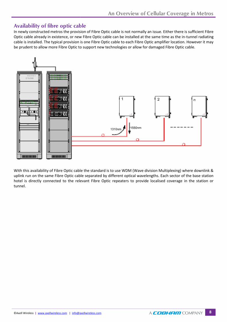
Availability of fibre optic cable In newly constructed metros the provision of Fibre Optic cable is not normally an issue. Either there is sufficient Fibre Optic cable already in existence, or new Fibre Optic cable can be installed at the same time as the in-tunnel radiating cable is installed. The typical provision is one Fibre Optic cable to each Fibre Optic amplifier location. However it may be prudent to allow more Fibre Optic to support new technologies or allow for damaged Fibre Optic cable.
With this availability of Fibre Optic cable the standard is to use WDM (Wave division Multiplexing) where downlink & uplink run on the same Fibre Optic cable separated by different optical wavelengths. Each sector of the base station hotel is directly connected to the relevant Fibre Optic repeaters to provide localised coverage in the station or tunnel.

An Overview of Cellular Coverage in Metros
©Axell Wireless | www.axellwireless.com | [email protected] 9
If however Fibre Optical cable is limited, which may happen in older metros or where new technologies are being coupled on to an existing system CWDM (Coarse Wave Division Multiplexing) can be utilised.
With CWDM up to 5 optical repeaters can share the same single mono mode fibre cable. A common downlink wavelength, typically 1310nm is fed to each repeater, whilst a separate uplink wavelength is utilised, where 20nm separation between repeater UL is deployed to avoid interference. A temperature stability of 0.08nm per °C is used to ensure that even with temperature drift interference between uplinks is eliminated.
Conclusion The use of Fibre Optic systems has, as previously highlighted, been adopted as the standard solution for provisioning RF communication system in metros not just for cellular but also public safety and train communications. The solution has many benefits over BTS feed systems including:
i) Reduced size, allowing easier access to the metro environment ii) Dynamic capacity allocation, where capacity from a BTS hotel is available at all connected station
simultaneously ensuring that the design capacity is utilised rather that being dedicated to a specific station / tunnel section
iii) Trunking efficiency, where more Erlang capacity is made available to the system using less TRx iv) Additional capacity can be added to any part of a Fibre Optic system by adding dedicated TRx at the BTS hotel.
In a BTS only system, this has to be done per station v) New technologies can be introduced with minimal change to the existing system as the Fibre Optic link to all
the repeaters is capable of supporting them.

An Overview of Cellular Coverage in Metros
©Axell Wireless | www.axellwireless.com | [email protected] 10
Axell Wireless solution The Fibre Optic Master Unit (OMU) can be equipped to support multiple Fibre Optic repeaters (MBF) The OMU is a 19” rack mounted unit. Each rack supports six optic modules. It is possible to link 4 chassis together to one logical unit allowing up to 24 optical modules to run from one OMU. The OMU master has an integrated modem which allows the repeaters to transmit statistics and alarms to a network management system. It is equipped with four External Alarms and a dry contact for sum alarm purposes. The OMU holds two power supplies to ensure redundancy.
The MBF is a Fibre Optic one, two or three band repeater. It provides high output power and great coverage for distributed antenna systems or radiating cables. One single mode Fibre Optic cable is needed for each repeater site. 900 MHz: 37 dBm composite output power (GSM, ETSI) 1800 MHz 37 dBm composite output power (DCS, ETSI) 2200MHz: 39 dBm composite (UMTS PAR 8.5dB) Wall Mount IP 65 rated enclosure. The triband band repeater is optimized for maximum efficiency in metro applications, resulting in a very compact and convection cooled unit. This unique solution allows for the unit to be installed in very rough environment. Since no active fan cooling is required, the MTBF is maximized and the OPEX significantly reduced.

An Overview of Cellular Coverage in Metros
©Axell Wireless | www.axellwireless.com | [email protected] 11
Key benefits of Axell Wireless fibre optic system All the tunnel and station located Fibre Optic Repeaters (MBFs) are Convection cooled & IP 65 rated.
o Ideal for dirty Metro Environments where moisture & brake dust is common. o Reduced maintenance – reduced OPEX
The input connectivity and be adjusted to suit operators requirements providing flexible sectorisation at FOM. o As capacity grows or changes, the sectorisation of the OMU can also change
The MBFs have an industry leading, very low uplink noise figure o Reduced uplink noise improves Rx receive sensitivity at BTS improving service quality o Additionally, it is possible to run more Fibre Optic repeaters on the same sector before the BTS sensitivity is
affected.
The MBFs have very low power consumption o Provision of supply within a metro environment is much easier as a single 240V supply is required at each
repeater location o Reduced power consumptions reduces the OPEX cost to the users
Upgradeable to support LTE o Axell Wireless Fibre Optic can support any system from 60MHz through to 3GHz, allowing many
technologies to share the same fibre link reducing equipment and installation costs. WDM or CWDM Fibre Optic distribution available

Thank you for reading this White Paper from Axell Wireless, a Cobham company
Axell Wireless, A Cobham Company, Aerial House, Asheridge Road, Chesham, Bucks, HP5 2QD, UK Tel: +44 (0) 1494 777 000 | Email: [email protected]
www.axellwireless.com